EP3573190A1 - Dummy pin - Google Patents
Dummy pin Download PDFInfo
- Publication number
- EP3573190A1 EP3573190A1 EP19170825.4A EP19170825A EP3573190A1 EP 3573190 A1 EP3573190 A1 EP 3573190A1 EP 19170825 A EP19170825 A EP 19170825A EP 3573190 A1 EP3573190 A1 EP 3573190A1
- Authority
- EP
- European Patent Office
- Prior art keywords
- waterproof
- dummy pin
- terminal insertion
- main body
- insertion port
- Prior art date
- Legal status (The legal status is an assumption and is not a legal conclusion. Google has not performed a legal analysis and makes no representation as to the accuracy of the status listed.)
- Granted
Links
Images


Classifications
-
- H—ELECTRICITY
- H01—ELECTRIC ELEMENTS
- H01R—ELECTRICALLY-CONDUCTIVE CONNECTIONS; STRUCTURAL ASSOCIATIONS OF A PLURALITY OF MUTUALLY-INSULATED ELECTRICAL CONNECTING ELEMENTS; COUPLING DEVICES; CURRENT COLLECTORS
- H01R13/00—Details of coupling devices of the kinds covered by groups H01R12/70 or H01R24/00 - H01R33/00
- H01R13/44—Means for preventing access to live contacts
- H01R13/443—Dummy plugs
-
- H—ELECTRICITY
- H01—ELECTRIC ELEMENTS
- H01R—ELECTRICALLY-CONDUCTIVE CONNECTIONS; STRUCTURAL ASSOCIATIONS OF A PLURALITY OF MUTUALLY-INSULATED ELECTRICAL CONNECTING ELEMENTS; COUPLING DEVICES; CURRENT COLLECTORS
- H01R13/00—Details of coupling devices of the kinds covered by groups H01R12/70 or H01R24/00 - H01R33/00
- H01R13/46—Bases; Cases
- H01R13/502—Bases; Cases composed of different pieces
-
- H—ELECTRICITY
- H01—ELECTRIC ELEMENTS
- H01R—ELECTRICALLY-CONDUCTIVE CONNECTIONS; STRUCTURAL ASSOCIATIONS OF A PLURALITY OF MUTUALLY-INSULATED ELECTRICAL CONNECTING ELEMENTS; COUPLING DEVICES; CURRENT COLLECTORS
- H01R13/00—Details of coupling devices of the kinds covered by groups H01R12/70 or H01R24/00 - H01R33/00
- H01R13/46—Bases; Cases
- H01R13/52—Dustproof, splashproof, drip-proof, waterproof, or flameproof cases
-
- H—ELECTRICITY
- H01—ELECTRIC ELEMENTS
- H01R—ELECTRICALLY-CONDUCTIVE CONNECTIONS; STRUCTURAL ASSOCIATIONS OF A PLURALITY OF MUTUALLY-INSULATED ELECTRICAL CONNECTING ELEMENTS; COUPLING DEVICES; CURRENT COLLECTORS
- H01R13/00—Details of coupling devices of the kinds covered by groups H01R12/70 or H01R24/00 - H01R33/00
- H01R13/46—Bases; Cases
- H01R13/52—Dustproof, splashproof, drip-proof, waterproof, or flameproof cases
- H01R13/5202—Sealing means between parts of housing or between housing part and a wall, e.g. sealing rings
-
- H—ELECTRICITY
- H01—ELECTRIC ELEMENTS
- H01R—ELECTRICALLY-CONDUCTIVE CONNECTIONS; STRUCTURAL ASSOCIATIONS OF A PLURALITY OF MUTUALLY-INSULATED ELECTRICAL CONNECTING ELEMENTS; COUPLING DEVICES; CURRENT COLLECTORS
- H01R13/00—Details of coupling devices of the kinds covered by groups H01R12/70 or H01R24/00 - H01R33/00
- H01R13/46—Bases; Cases
- H01R13/52—Dustproof, splashproof, drip-proof, waterproof, or flameproof cases
- H01R13/5205—Sealing means between cable and housing, e.g. grommet
- H01R13/5208—Sealing means between cable and housing, e.g. grommet having at least two cable receiving openings
-
- H—ELECTRICITY
- H01—ELECTRIC ELEMENTS
- H01R—ELECTRICALLY-CONDUCTIVE CONNECTIONS; STRUCTURAL ASSOCIATIONS OF A PLURALITY OF MUTUALLY-INSULATED ELECTRICAL CONNECTING ELEMENTS; COUPLING DEVICES; CURRENT COLLECTORS
- H01R13/00—Details of coupling devices of the kinds covered by groups H01R12/70 or H01R24/00 - H01R33/00
- H01R13/46—Bases; Cases
- H01R13/52—Dustproof, splashproof, drip-proof, waterproof, or flameproof cases
- H01R13/5219—Sealing means between coupling parts, e.g. interfacial seal
- H01R13/5221—Sealing means between coupling parts, e.g. interfacial seal having cable sealing means
-
- H—ELECTRICITY
- H01—ELECTRIC ELEMENTS
- H01R—ELECTRICALLY-CONDUCTIVE CONNECTIONS; STRUCTURAL ASSOCIATIONS OF A PLURALITY OF MUTUALLY-INSULATED ELECTRICAL CONNECTING ELEMENTS; COUPLING DEVICES; CURRENT COLLECTORS
- H01R13/00—Details of coupling devices of the kinds covered by groups H01R12/70 or H01R24/00 - H01R33/00
- H01R13/46—Bases; Cases
- H01R13/52—Dustproof, splashproof, drip-proof, waterproof, or flameproof cases
- H01R13/521—Sealing between contact members and housing, e.g. sealing insert
Definitions
- the present invention relates to a dummy pin, particularly to a dummy pin that is inserted into a terminal insertion port into which a terminal is not inserted among a plurality of terminal insertion ports of a waterproof connector.
- a waterproof connector in which a seal member having a plurality of seal holes corresponding to a plurality of terminal insertion ports formed at a housing is attached to the housing so that terminals are to be inserted from the terminal insertion ports of the housing into the corresponding terminal accommodating portions in the housing through the seal holes of the seal member.
- JP 2004-71200 A discloses a dummy pin 1 made of resin for filling a terminal insertion port as shown in FIG. 15 .
- the dummy pin 1 has a cylindrical seal portion 3 projecting forward from a rectangular parallelepiped main body 2, hook portions 4 respectively projecting on an upper surface and a lower surface of the main body 2, and a flange portion 5 formed at a rear portion of the main body 2.
- a waterproof connector 6 has a structure that a seal member 8 is disposed in a concave portion 7B communicating with a terminal accommodating portion 7A of a housing 7 and a cover 9 is attached to a rear end of the housing 7.
- a seal member 8 is disposed in a concave portion 7B communicating with a terminal accommodating portion 7A of a housing 7 and a cover 9 is attached to a rear end of the housing 7.
- the hook portions 4 of the dummy pin 1 go over projections 9B respectively projecting on an upper edge and a lower edge of the terminal insertion port 9A of the cover 9 and accordingly, the projections 9B are positioned between the hook portions 4 and the flange portion 5 of the dummy pin 1, which prevents the dummy pin 1 from falling off the waterproof connector 6.
- the dummy pin 1 disclosed by JP 2004-71200 A is prevented from falling off by making the hook portions 4 respectively projecting on the upper surface and the lower surface of the main body 2 catch on the projections 9B respectively projecting on the upper edge and the lower edge of the terminal insertion port 9A of the cover 9, the dummy pin 1 cannot be inserted into the waterproof connector 6 in a normal manner unless the hook portions 4 project in the particular direction, i.e., the vertical direction.
- a parting line along the central axis direction is generated on an outer peripheral surface of the seal portion 3 after molding, whereby the outer peripheral surface of the seal portion 3 cannot form a continuous surface over the whole circumference thereof. Since the parting line causes formation of projections, bumps and the like, even if the dummy pin 1 as above is inserted into the waterproof connector 6, tight contact between an inner surface of the seal hole 8A of the seal member 8 and the seal portion 3 of the dummy pin 1 in the waterproof connector 6 becomes insufficient, which may degrade waterproof properties.
- the present invention has been made to eliminate the conventional drawback as above and is aimed at providing a dummy pin that can achieve excellent waterproof properties without a complicated structure of a waterproof connector and regardless of a direction of insertion to the waterproof connector.
- a dummy pin according to the present invention is one for use in a waterproof connector, the waterproof connector including: a housing that has at least one terminal insertion port; and a waterproof member that is elastically deformable, is disposed in the housing and has at least one seal hole corresponding to the at least one terminal insertion port and having a central axis, the at least one seal hole having two or more lip portions that annularly project toward the central axis and are aligned in a direction of the central axis, the dummy pin comprising:
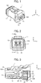
- FIGS. 1 and 2 show a waterproof connector 11 to which a dummy pin according to the present invention is applied.
- the waterproof connector 11 has a housing 12 formed of resin, two front face opening portions 13 and 14 into each of which a terminal of a counter connector (not shown) is inserted during fitting with the counter connector are formed on a front face 12A of the housing 12, and two terminal insertion ports 15 and 16 open at a rear face 12B opposite to the front face 12A.
- the housing 12 is constituted of a housing main body 17 and a rear cover 18 disposed at a rear portion of the housing main body 17.
- the housing main body 17 has the front face opening portions 13 and 14, and the rear cover 18 has the terminal insertion ports 15 and 16.
- the direction which extends from the front face 12A to the rear face 12B of the housing 12 is called “+Y direction”
- the direction in which the two terminal insertion ports 15 and 16 are aligned is called “X direction”
- the direction perpendicular to an XY plane is called “Z direction.”
- the counter connector (not shown) is fitted into the waterproof connector 11 from the -Y direction to the +Y direction.
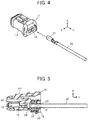
- FIG. 3 is a cross-sectional side view of the waterproof connector 11 cut at a position of the terminal insertion port 15.
- a terminal accommodating portion 19 of recess shape communicating with the terminal insertion port 15 is formed inside the housing main body 17.
- a concave portion 20 is formed inside the housing main body 17 so as to be adjacent to the +Y direction side of the terminal accommodating portion 19, and a waterproof member 21 is disposed in the concave portion 20.
- the waterproof member 21 is made of, for example, an elastically deformable material such as a rubber material, and a seal hole 22 communicating with the terminal insertion port 15 and having a central axis C1 is formed in the waterproof member 21.
- Two lip portions 23 and 24 that annularly project toward the central axis C1 and are aligned in the direction of the central axis C1 are formed inside the seal hole 22.
- Each of the two lip portions 23 and 24 has an inside diameter smaller than that of the terminal insertion port 15 of the rear cover 18, and the lip portion 23 is positioned closer to the rear face 12B side, i.e., the +Y direction side of the housing 12 than the lip portion 24 is.
- the waterproof member 21 is held in the concave portion 20 by fixing the rear cover 18 to the rear portion of the housing main body 17.
- a terminal accommodating portion 19 communicating with the terminal insertion port 16 is also formed inside the housing main body 17, and as with the seal hole 22 communicating with the terminal insertion port 15, a seal hole 22 communicating with the terminal insertion port 16 is also formed in the waterproof member 21, and two lip portions 23 and 24 are formed inside the seal hole 22 communicating with the terminal insertion port 16.
- the two terminal accommodating portions 19 are formed inside the housing main body 17 and the two seal holes 22 are formed in the waterproof member 21 such that the portions 19 and the holes 22 correspond to the two terminal insertion ports 15 and 16.
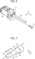
- a terminal 31 used in the waterproof connector 11 is connected to an end of an electrical wire 32 and is attached to the inside of the waterproof connector 11 by inserting the terminal 31 in the -Y direction from, for example, the terminal insertion port 15 of the waterproof connector 11.
- the electric wire 32 is set to have an outside diameter larger than each of the inside diameters of the two lip portions 23 and 24 of the waterproof member 21.
- the terminal 31 When the terminal 31 is inserted in the -Y direction from the terminal insertion port 15 of the waterproof connector 11, the terminal 31 passes through the seal hole 22 of the waterproof member 21 from the terminal insertion port 15 and is accommodated in the terminal accommodating portion 19 in the housing main body 17 as shown in FIG. 5 . At this time, the electric wire 32 connected to the terminal 31 is inserted into the seal hole 22 of the waterproof member 21 and makes tight contact with an inner surface of the seal hole 22 while elastically compressing the two lip portions 23 and 24 projecting in the seal hole 22. This prevents water intrusion to the terminal accommodating portion 19 through the terminal insertion port 15.
- the terminal 31 shown in FIGS. 4 and 5 is a receptacle terminal, and a plug terminal of the counter connector (not shown) is inserted into the terminal 31 through the front face opening portion 13 during a fitting process with the counter connector, whereby the counter connector is electrically connected to the terminal 31.
- the electrical wire 32 connected to the terminal 31 is fitted into each of the two seal holes 22 formed in the waterproof member 21, which prevents water intrusion into the waterproof connector 11.
- the terminal 31 is inserted into the only terminal insertion port 15, i.e., only one of the two terminal insertion ports 15 and 16, with the other terminal insertion port 16 being not used and the terminal 31 being not inserted into the terminal insertion port 16, it is necessary to fill the terminal insertion port 16 in order to prevent water intrusion into the waterproof connector 11.
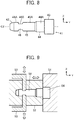
- a dummy pin 41 according to Embodiment 1 is inserted into the terminal insertion port 16 of the waterproof connector 11.
- the dummy pin 41 is a pin-shaped member extending along a central axis C2 and is produced by resin molding.
- the dummy pin 41 is constituted of a pin main body 42 and a head portion 43 joined to one end in the length direction of the pin main body 42, i.e, the +Y direction end of the pin main body 42.
- the pin main body 42 is accommodated in the housing 12 of the waterproof connector 11 when the dummy pin 41 is inserted into the terminal insertion port 16 of the waterproof connector 11, and the pin main body 42 has a fitting portion 44, a waterproof portion 45 and a falling-off prevention portion 46 that are sequentially aligned from +Y direction end connected to the head portion 43 toward the -Y direction end.
- the waterproof portion 45 has a cylindrical seal surface 45A.
- the seal surface 45A has an outside diameter larger than the inside diameter of each of the lip portions 23 and 24 of the waterproof member 21 disposed in the waterproof connector 11 and forms a continuous surface over the entire circumferential direction of the waterproof portion 45.
- the falling-off prevention portion 46 is disposed adjacent to the -Y direction side of the waterproof portion 45.
- the falling-off prevention portion 46 has a cylindrical outer peripheral surface 46A that is continuous with the seal surface 45A of the waterproof portion 45 and that has an outer diameter equal to that of the seal surface 45A, and a pair of concave portions 46B that are formed at the outer peripheral surface 46A so as to face in opposite directions to each other in a direction perpendicular to the central axis C2 of the dummy pin 41.
- the lip portion 24 positioned on the -Y direction side enters the pair of concave portions 46B, which prevents the dummy pin 41 from falling off.
- the +Y direction end surface of the concave portion 46B is inclined in an obtuse angle direction with respect to the bottom surface of the concave portion 46B, and the -Y direction end surface of the concave portion 46B is upright to the bottom surface of the concave portion 46B.
- the pin main body 42 is configured such that a portion thereof positioned on the -Y direction side of the waterproof portion 45 has an outside diameter equal to or smaller than that of the seal surface 45A.
- the fitting portion 44 has a cylindrical outer peripheral surface 44A having an outside diameter larger than that of the seal surface 45A of the waterproof portion 45 and slightly smaller than the inside diameter of the terminal insertion port 16, and when the dummy pin 41 is inserted into the terminal insertion port 16 of the waterproof connector 11, the fitting portion 44 is fitted with the terminal insertion port 16.
- the head portion 43 joined to the +Y direction end of the pin main body 42 has an outside diameter larger than the inside diameter of the terminal insertion port 16 of the waterproof connector 11, and when the dummy pin 41 is inserted into the terminal insertion port 16 of the waterproof connector 16, the head portion 43 functions as a stopper that comes into contact with the rear face 12B of the housing 12 at which the terminal insertion port 16 opens.
- the dummy pin 41 as above can be produced by resin molding using a shape-forming mold as shown in FIG. 9 , for example.
- the shape-forming mold is constituted of a fixed mold 51, a movable mold 52 that is disposed to be movable in the Y direction with respect to the fixed mold 51, and a pair of slide molds 53 that are incorporated in the movable mold 52 and slide in the Z direction in response to the movement of the movable mold 52.
- the fixed mold 51 has a cavity 54 corresponding to the head portion 43 of the dummy pin 41 and a gate (not shown) for injecting molten resin R in the cavity 54.
- the movable mold 52 has a cavity 56 corresponding to the pin main body 42 of the dummy pin 41.
- the parting plane between the fixed mold 51 and the movable mold 52 is set at the boundary between the pin main body 42 and the head portion 43, the boundary being perpendicular to the central axis C2 of the dummy pin 41.
- Tip ends of the pair of slide molds 53 that are incorporated in the movable mold 52 have a shape corresponding to the pair of concave portions 46B of the falling-off prevention portion 46 of the dummy pin 41, and as shown in FIG. 9 , when the movable mold 52 comes into contact with the fixed mold 51 so as to close the shape-forming mold, each of the slide molds 53 advances toward the cavity 56 of the movable mold 52 and the tip ends of the slide molds 53 project in the cavity 56 of the movable mold 52.
- each of the slide molds 53 is retracted from the cavity 56 of the movable mold 52, and the tip ends of the slide molds 53 move away from the cavity 56 of the movable mold 52.
- the molten resin R is injected into the cavities 54 and 56 through the gate (not shown) in the fixed mold 51.
- the shape-forming mold is opened by moving the movable mold 52 in the -Y direction.
- the dummy pin 41 thus molded can be extracted by being pulled out in the Y direction from the fixed mold 51 and the movable mold 52.
- a shape-forming mold can be constituted of a movable mold having the cavity 54 and a fixed mold having the cavity 56.
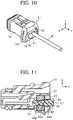
- FIG. 10 shows the waterproof connector 11 in which the dummy pin 41 is inserted in the terminal insertion port 16.
- the terminal 31 not shown in FIG. 10 is inserted in one of the two terminal insertion ports 15 and 16 of the waterproof connector 11, i.e., the terminal insertion port 15, the electric wire 32 connected to the terminal 31 is led out from the terminal insertion port 15, and the dummy pin 41 is inserted in the other port, i.e., the terminal insertion port 16.
- the head portion 43 of the dummy pin 41 is in contact with the rear face 12B of the housing 12.
- the seal surface 45A of the waterproof portion 45 of the dummy pin 41 is located at a position of the lip portion 23 of the +Y direction side of the waterproof member 21 and has an outside diameter larger than the inside diameter of the lip portion 23, the seal surface 45A makes tight contact with the inner surface of the seal hole 22 by elastically compressing the lip portion 23. This prevents water intrusion into the housing 12 through the terminal insertion port 16.
- the seal surface 45A of the waterproof portion 45 of the dummy pin 41 does not have a parting line caused by resin molding and forms a continuous surface over the entire circumferential direction of the waterproof portion 45, the inner surface of the seal hole 22 of the waterproof member 21 and the seal surface 45A of the dummy pin 41 makes sufficiently tight contact with each other, thus achieving excellent waterproof properties.
- the -Y direction end surface of the concave portion 46B formed in the falling-off prevention portion 46 of the dummy pin 41 is upright to the bottom surface of the concave portion 46B as described above, even if an external force that attempts to pull the dummy pin 41 out toward the +Y direction is applied to the dummy pin 41, the -Y direction end surface of the concave portion 46B catches on the lip portion 24 of the waterproof member 21, which effectively prevents pull-out of the dummy pin 41. Therefore, even if the internal pressure of the waterproof connector 11 rises, the dummy pin 41 can be prevented from falling off the terminal insertion port 16 and thus water intrusion into the waterproof connector 11 can be prevented.
- the dummy pin 41 includes the fitting portion 44 having the cylindrical outer peripheral surface 44A, the waterproof portion 45 having the cylindrical seal surface 45A, and the falling-off prevention portion 46 having the cylindrical outer peripheral surface 46A and the pair of concave portions 46B formed on the outer peripheral surface 46A, and the annular lip portion 24 of the waterproof member 21 of the waterproof connector 11 enters the concave portions 46B of the falling-off prevention portion 46 of the dummy pin 41; therefore, the dummy pin 41 can be inserted into the terminal insertion port 16 of the waterproof connector 11 in a normal manner irrespective of the angle position around the central axis C2 of the dummy pin 41.
- the dummy pin 41 can be inserted into the terminal insertion port 16 of the waterproof connector 11 to prevent water intrusion into the waterproof connector 11 and generate a falling-off prevention function.
- the waterproof portion 45 may be positioned on the -Y direction side of the falling-off prevention portion 46 such that, from the head portion 43, the fitting portion 44, the falling-off prevention portion 46 and the waterproof portion 45 are sequentially aligned.
- the seal surface 45A of the waterproof portion 45 makes tight contact with the inner surface of the seal hole 22 by elastically compressing the lip portion 24 of the -Y direction side of the waterproof member 21, and the lip portion 23 of the +Y direction side of the waterproof member 21 enter the concave portion 46B of the falling-off prevention portion 46, which prevents the dummy pin 61 from falling off.
- the falling-off prevention portion 46 has the pair of concave portions 46B facing the opposite directions with each other, the invention is not limited thereto; even when the falling-off prevention portion 46 has only one concave portion 46B, the lip portion 23 or 24 of the waterproof member 21 enters this concave portion 46B, which prevents the dummy pins 41 and 61 from falling off. Further, even when the falling-off prevention portion 46 has three or more concave portions 46B, the dummy pins 41 and 61 can be prevented from falling off in the same manner.
- the waterproof member 21 of the waterproof connector 11 has the two lip portions 23 and 24 projecting inside the seal hole 22, the invention is not limited thereto; the waterproof member 21 may have three or more lip portions that annularly project toward the central axis C1 and are aligned in the direction of the central axis C1 inside the seal hole 22.
- the seal surface 45A of the waterproof portion 45 of the dummy pin 41 or 61 makes tight contact with the inner surface of the seal hole 22 by elastically compressing a part of the three or more lip portions, and the remaining lip portion(s) of the three or more lip portions enters the concave portions 46B of the falling-off prevention portion 46 of the dummy pin 41 or 61.
- the waterproof connector 11 has the two terminal insertion ports 15 and 16, the invention is not limited thereto; the dummy pin 41 or 61 can be applied to a waterproof connector having three of more terminal insertion ports.
- the waterproof connector may have three or more terminal accommodating portions corresponding to the three or more terminal insertion ports in the housing, the waterproof member disposed in the housing may have three or more seal holes corresponding to the three or more terminal insertion ports, and two or more lip portions may be formed in each of the seal holes.
- a terminal is inserted into a part of the terminal insertion ports and the dummy pin 41 or 61 is inserted into the remaining terminal insertion port(s) into which the terminal is not inserted, which prevents water intrusion into the waterproof connector.
- a dummy pin 71 according to Embodiment 2 is shown in FIGS. 13 and 14 .
- This dummy pin 71 is obtained by disposing a fitting portion 74 instead of the fitting portion 44 between the head portion 43 and the waterproof portion 45 in the dummy pin 41 according to Embodiment 1 shown in FIGS. 7 and 8 , and the other configuration is the same as that of the dummy pin 41 according to Embodiment 1.
- the fitting portion 74 has a cylindrical outer peripheral surface 74A having an outside diameter larger than that of the seal surface 45A of the waterproof portion 45 and slightly smaller than the inside diameter of the terminal insertion port 16 of the waterproof connector 11, and a plurality of press-fitting ribs 74B formed on the outer peripheral surface 74A.
- the plurality of press-fitting ribs 74B are disposed at equal intervals in a circumferential direction of the outer peripheral surface 74A and each extend in parallel with the central axis C2 of the dummy pin 71.
- the top section of each of the plurality of press-fitting libs 74B, i.e., the portion most distant from the central axis C2 is positioned on a circumference having a diameter slightly larger than the inside diameter of the terminal insertion port 16 of the waterproof connector 11, and when the dummy pin 71 is inserted into the terminal insertion port 16 of the waterproof connector 11, the plurality of press-fitting ribs 74B are press-fitted into the terminal insertion port 16.
- the dummy pin 71 according to Embodiment 2 has a structure which prevents the dummy pin 71 from falling off the waterproof connector 11 more efficiently than the dummy pin 41 of Embodiment 1, whereby a waterproof function by the dummy pin 71 can be reliably maintained.
- the head portion 43 of the above-described dummy pin 41, 61 or 71 has a circular cylindrical shape, the invention is not limited thereto.
- the head portion 43 only needs to function as a stopper when the dummy pin 41, 61 or 71 is inserted into the terminal insertion port 16 of the waterproof connector 11, and may have, for example, a polygonal column shape having a size larger than the inside diameter of the terminal insertion port 16.
- the shape of the concave portion partially recessed the seal surface of the dummy pin toward the central axis can be changed in various ways.
- the dummy pin when the diameters of the cylindrical outer peripheral surface 44A of the fitting portion 44, the cylindrical seal surface 45A of the waterproof portion 45, and the cylindrical outer peripheral surface 46A of the falling-off prevention portion 46 gradually decrease toward the -Y direction, the dummy pin can readily fall off the shape-forming mold; even if the dummy pin has a shape that the diameter thereof gradually decreases toward the -Y direction, the waterproof function and the falling-off prevention function are not changed as compared with the dummy pin having a shape in which the diameter thereof does not gradually decrease.
Landscapes
- Connector Housings Or Holding Contact Members (AREA)
Abstract
Description
- The present invention relates to a dummy pin, particularly to a dummy pin that is inserted into a terminal insertion port into which a terminal is not inserted among a plurality of terminal insertion ports of a waterproof connector.
- Conventionally, there is known a waterproof connector in which a seal member having a plurality of seal holes corresponding to a plurality of terminal insertion ports formed at a housing is attached to the housing so that terminals are to be inserted from the terminal insertion ports of the housing into the corresponding terminal accommodating portions in the housing through the seal holes of the seal member.
- In a waterproof connector of this type, when a terminal insertion port into which no terminal is inserted is present among the plurality of terminal insertion ports, it is necessary to fill the terminal insertion port into which no terminal is inserted in order to prevent water intrusion into the waterproof connector.
- To cope with it, for example,
JP 2004-71200 A dummy pin 1 made of resin for filling a terminal insertion port as shown inFIG. 15 . Thedummy pin 1 has acylindrical seal portion 3 projecting forward from a rectangular parallelepipedmain body 2,hook portions 4 respectively projecting on an upper surface and a lower surface of themain body 2, and aflange portion 5 formed at a rear portion of themain body 2. - As shown in
FIG. 16 , awaterproof connector 6 has a structure that aseal member 8 is disposed in aconcave portion 7B communicating with aterminal accommodating portion 7A of ahousing 7 and acover 9 is attached to a rear end of thehousing 7. When thedummy pin 1 is inserted into aterminal insertion port 9A formed in thecover 9, theseal portion 3 of thedummy pin 1 is fitted into aseal hole 8A of theseal member 8, which prevents water intrusion to theterminal accommodating portion 7A. - Further, when the
dummy pin 1 is firmly pushed into thewaterproof connector 6, thehook portions 4 of thedummy pin 1 go overprojections 9B respectively projecting on an upper edge and a lower edge of theterminal insertion port 9A of thecover 9 and accordingly, theprojections 9B are positioned between thehook portions 4 and theflange portion 5 of thedummy pin 1, which prevents thedummy pin 1 from falling off thewaterproof connector 6. - However, since the
dummy pin 1 disclosed byJP 2004-71200 A hook portions 4 respectively projecting on the upper surface and the lower surface of themain body 2 catch on theprojections 9B respectively projecting on the upper edge and the lower edge of theterminal insertion port 9A of thecover 9, thedummy pin 1 cannot be inserted into thewaterproof connector 6 in a normal manner unless thehook portions 4 project in the particular direction, i.e., the vertical direction. - Further, there is a problem in that the structure of the
waterproof connector 6 becomes complicated since in order to prevent thedummy pin 1 from falling off, it is necessary not only to form thehook portions 4 projecting on thedummy pin 1 but also to form theprojections 9B projecting on the upper edge and the lower edge of theterminal insertion port 9A of thecover 9 which is a component of thewaterproof connector 6. - Further, in order to mold resin into the
dummy pin 1 having the structure that thehook portions 4 respectively project on the upper surface and the lower surface of themain body 2 as shown inFIG. 15 , it is necessary to use a metal mold that is divided in a direction perpendicular to a central axis along which theseal portion 3 of thedummy pin 1 extends to take out thedummy pin 1 from the metal mold after molding. - Therefore, due to the divided surface of the metal mold, a parting line along the central axis direction is generated on an outer peripheral surface of the
seal portion 3 after molding, whereby the outer peripheral surface of theseal portion 3 cannot form a continuous surface over the whole circumference thereof. Since the parting line causes formation of projections, bumps and the like, even if thedummy pin 1 as above is inserted into thewaterproof connector 6, tight contact between an inner surface of theseal hole 8A of theseal member 8 and theseal portion 3 of thedummy pin 1 in thewaterproof connector 6 becomes insufficient, which may degrade waterproof properties. - The present invention has been made to eliminate the conventional drawback as above and is aimed at providing a dummy pin that can achieve excellent waterproof properties without a complicated structure of a waterproof connector and regardless of a direction of insertion to the waterproof connector.
- A dummy pin according to the present invention is one for use in a waterproof connector, the waterproof connector including: a housing that has at least one terminal insertion port; and a waterproof member that is elastically deformable, is disposed in the housing and has at least one seal hole corresponding to the at least one terminal insertion port and having a central axis, the at least one seal hole having two or more lip portions that annularly project toward the central axis and are aligned in a direction of the central axis, the dummy pin comprising:
- a pin main body that is to be inserted into the at least one terminal insertion port and is formed by molding resin,
- wherein the pin main body has: a waterproof portion having a cylindrical seal surface that makes tight contact with an inner surface of the at least one seal hole by elastically compressing a part of the two or more lip portions of the waterproof member; and a falling-off prevention portion having one or more concave portions that are partially recessed from the seal surface toward the central axis and that a remaining lip portion of the two or more lip portions of the waterproof member enters, and
- the seal surface forms a continuous surface over an entire circumferential direction of the waterproof portion.
-
-
FIG. 1 is a perspective view showing a waterproof connector. -
FIG. 2 is a front view showing the waterproof connector. -
FIG. 3 is a cross-sectional view taken along line A-AinFIG. 2 . -
FIG. 4 is a perspective view showing the state where a terminal is being inserted into the waterproof connector. -
FIG. 5 is a cross-sectional side view showing the waterproof connector into which the terminal is inserted. -
FIG. 6 is a perspective view showing the state where a dummy pin according toEmbodiment 1 is being inserted into the waterproof connector. -
FIG. 7 is a perspective view showing the dummy pin according to Embodiment 1. -
FIG. 8 is a side view showing the dummy pin according to Embodiment 1. -
FIG. 9 is a cross-sectional side view showing a shape-forming mold for molding the dummy pin according toEmbodiment 1. -
FIG. 10 is a perspective view showing the waterproof connector into which the dummy pin is inserted. -
FIG. 11 is a cross-sectional side view showing the waterproof connector into which the dummy pin is inserted. -
FIG. 12 is a side view showing a dummy pin according to a variation ofEmbodiment 1. -
FIG. 13 is a perspective view showing a dummy pin according to Embodiment 2. -
FIG. 14 is a side view showing the dummy pin according to Embodiment 2. -
Fig. 15 is a perspective view showing a conventional dummy pin. -
FIG. 16 is a cross-sectional side view showing a waterproof connector into which the conventional dummy pin is inserted. - Embodiments of the present invention are described below based on the appended drawings.
-
FIGS. 1 and 2 show awaterproof connector 11 to which a dummy pin according to the present invention is applied. Thewaterproof connector 11 has ahousing 12 formed of resin, two frontface opening portions front face 12A of thehousing 12, and twoterminal insertion ports rear face 12B opposite to thefront face 12A. - The
housing 12 is constituted of a housingmain body 17 and arear cover 18 disposed at a rear portion of the housingmain body 17. The housingmain body 17 has the frontface opening portions rear cover 18 has theterminal insertion ports - For convenience, the direction which extends from the
front face 12A to therear face 12B of thehousing 12 is called "+Y direction," the direction in which the twoterminal insertion ports waterproof connector 11 from the -Y direction to the +Y direction. -
FIG. 3 is a cross-sectional side view of thewaterproof connector 11 cut at a position of theterminal insertion port 15. A terminal accommodatingportion 19 of recess shape communicating with theterminal insertion port 15 is formed inside the housingmain body 17. - A
concave portion 20 is formed inside the housingmain body 17 so as to be adjacent to the +Y direction side of theterminal accommodating portion 19, and awaterproof member 21 is disposed in theconcave portion 20. Thewaterproof member 21 is made of, for example, an elastically deformable material such as a rubber material, and aseal hole 22 communicating with theterminal insertion port 15 and having a central axis C1 is formed in thewaterproof member 21. Twolip portions seal hole 22. - Each of the two
lip portions terminal insertion port 15 of therear cover 18, and thelip portion 23 is positioned closer to therear face 12B side, i.e., the +Y direction side of thehousing 12 than thelip portion 24 is. - The
waterproof member 21 is held in theconcave portion 20 by fixing therear cover 18 to the rear portion of the housingmain body 17. - Although not shown in
FIG. 3 , as with theterminal accommodating portion 19 communicating with theterminal insertion port 15, a terminal accommodatingportion 19 communicating with theterminal insertion port 16 is also formed inside the housingmain body 17, and as with theseal hole 22 communicating with theterminal insertion port 15, aseal hole 22 communicating with theterminal insertion port 16 is also formed in thewaterproof member 21, and twolip portions seal hole 22 communicating with theterminal insertion port 16. In other words, the two terminal accommodatingportions 19 are formed inside the housingmain body 17 and the twoseal holes 22 are formed in thewaterproof member 21 such that theportions 19 and theholes 22 correspond to the twoterminal insertion ports - As shown in
FIG. 4 , aterminal 31 used in thewaterproof connector 11 is connected to an end of anelectrical wire 32 and is attached to the inside of thewaterproof connector 11 by inserting theterminal 31 in the -Y direction from, for example, theterminal insertion port 15 of thewaterproof connector 11. Theelectric wire 32 is set to have an outside diameter larger than each of the inside diameters of the twolip portions waterproof member 21. - When the
terminal 31 is inserted in the -Y direction from theterminal insertion port 15 of thewaterproof connector 11, theterminal 31 passes through theseal hole 22 of thewaterproof member 21 from theterminal insertion port 15 and is accommodated in theterminal accommodating portion 19 in the housingmain body 17 as shown inFIG. 5 . At this time, theelectric wire 32 connected to theterminal 31 is inserted into theseal hole 22 of thewaterproof member 21 and makes tight contact with an inner surface of theseal hole 22 while elastically compressing the twolip portions seal hole 22. This prevents water intrusion to theterminal accommodating portion 19 through theterminal insertion port 15. - The
terminal 31 shown inFIGS. 4 and 5 is a receptacle terminal, and a plug terminal of the counter connector (not shown) is inserted into theterminal 31 through the frontface opening portion 13 during a fitting process with the counter connector, whereby the counter connector is electrically connected to theterminal 31. - When the
terminal 31 is thus inserted into each of the twoterminal insertion ports waterproof connector 11, theelectrical wire 32 connected to theterminal 31 is fitted into each of the twoseal holes 22 formed in thewaterproof member 21, which prevents water intrusion into thewaterproof connector 11. However, when theterminal 31 is inserted into the onlyterminal insertion port 15, i.e., only one of the twoterminal insertion ports terminal insertion port 16 being not used and theterminal 31 being not inserted into theterminal insertion port 16, it is necessary to fill theterminal insertion port 16 in order to prevent water intrusion into thewaterproof connector 11. - To cope with it, as shown in
FIG. 6 , adummy pin 41 according toEmbodiment 1 is inserted into theterminal insertion port 16 of thewaterproof connector 11. - As shown in
FIGS. 7 and8 , thedummy pin 41 is a pin-shaped member extending along a central axis C2 and is produced by resin molding. Thedummy pin 41 is constituted of a pinmain body 42 and ahead portion 43 joined to one end in the length direction of the pinmain body 42, i.e, the +Y direction end of the pinmain body 42. - The pin
main body 42 is accommodated in thehousing 12 of thewaterproof connector 11 when thedummy pin 41 is inserted into theterminal insertion port 16 of thewaterproof connector 11, and the pinmain body 42 has afitting portion 44, awaterproof portion 45 and a falling-off prevention portion 46 that are sequentially aligned from +Y direction end connected to thehead portion 43 toward the -Y direction end. - The
waterproof portion 45 has acylindrical seal surface 45A. Theseal surface 45A has an outside diameter larger than the inside diameter of each of thelip portions waterproof member 21 disposed in thewaterproof connector 11 and forms a continuous surface over the entire circumferential direction of thewaterproof portion 45. When thedummy pin 41 is inserted into theterminal insertion port 16 of thewaterproof connector 11, theseal surface 45A is inserted into theseal hole 22 of thewaterproof member 21 and make tight contact with the inner surface of theseal hole 22 by elastically compressing, of the twolip portions seal hole 22, thelip portion 23 that is positioned on the +Y direction side. - The falling-
off prevention portion 46 is disposed adjacent to the -Y direction side of thewaterproof portion 45. The falling-off prevention portion 46 has a cylindrical outerperipheral surface 46A that is continuous with theseal surface 45A of thewaterproof portion 45 and that has an outer diameter equal to that of theseal surface 45A, and a pair ofconcave portions 46B that are formed at the outerperipheral surface 46A so as to face in opposite directions to each other in a direction perpendicular to the central axis C2 of thedummy pin 41. When thedummy pin 41 is inserted into theterminal insertion port 16 of thewaterproof connector 11, of the twolip portions waterproof member 21, thelip portion 24 positioned on the -Y direction side enters the pair ofconcave portions 46B, which prevents thedummy pin 41 from falling off. As shown inFIG. 8 , the +Y direction end surface of theconcave portion 46B is inclined in an obtuse angle direction with respect to the bottom surface of theconcave portion 46B, and the -Y direction end surface of theconcave portion 46B is upright to the bottom surface of theconcave portion 46B. - Thus, the pin
main body 42 is configured such that a portion thereof positioned on the -Y direction side of thewaterproof portion 45 has an outside diameter equal to or smaller than that of theseal surface 45A. - The
fitting portion 44 has a cylindrical outerperipheral surface 44A having an outside diameter larger than that of theseal surface 45A of thewaterproof portion 45 and slightly smaller than the inside diameter of theterminal insertion port 16, and when thedummy pin 41 is inserted into theterminal insertion port 16 of thewaterproof connector 11, thefitting portion 44 is fitted with theterminal insertion port 16. - The
head portion 43 joined to the +Y direction end of the pinmain body 42 has an outside diameter larger than the inside diameter of theterminal insertion port 16 of thewaterproof connector 11, and when thedummy pin 41 is inserted into theterminal insertion port 16 of thewaterproof connector 16, thehead portion 43 functions as a stopper that comes into contact with therear face 12B of thehousing 12 at which theterminal insertion port 16 opens. - The
dummy pin 41 as above can be produced by resin molding using a shape-forming mold as shown inFIG. 9 , for example. - The shape-forming mold is constituted of a fixed
mold 51, amovable mold 52 that is disposed to be movable in the Y direction with respect to the fixedmold 51, and a pair ofslide molds 53 that are incorporated in themovable mold 52 and slide in the Z direction in response to the movement of themovable mold 52. - The fixed
mold 51 has acavity 54 corresponding to thehead portion 43 of thedummy pin 41 and a gate (not shown) for injecting molten resin R in thecavity 54. - The
movable mold 52 has acavity 56 corresponding to the pinmain body 42 of thedummy pin 41. In other words, the parting plane between the fixedmold 51 and themovable mold 52 is set at the boundary between the pinmain body 42 and thehead portion 43, the boundary being perpendicular to the central axis C2 of thedummy pin 41. - Tip ends of the pair of
slide molds 53 that are incorporated in themovable mold 52 have a shape corresponding to the pair ofconcave portions 46B of the falling-off prevention portion 46 of thedummy pin 41, and as shown inFIG. 9 , when themovable mold 52 comes into contact with the fixedmold 51 so as to close the shape-forming mold, each of theslide molds 53 advances toward thecavity 56 of themovable mold 52 and the tip ends of theslide molds 53 project in thecavity 56 of themovable mold 52. On the other hand, when themovable mold 52 separates from the fixedmold 51 so as to open the shape-forming mold, each of theslide molds 53 is retracted from thecavity 56 of themovable mold 52, and the tip ends of theslide molds 53 move away from thecavity 56 of themovable mold 52. - As shown in
FIG. 9 , in the state where thecavity 54 of the fixedmold 51 and thecavity 56 of themovable mold 52 are connected to each other by closing the shape-forming mold as above, the molten resin R is injected into thecavities mold 51. After the resin is cooled and solidified, the shape-forming mold is opened by moving themovable mold 52 in the -Y direction. At this time, since the pair ofslide molds 53 are retracted from thecavity 56 of themovable mold 52, thedummy pin 41 thus molded can be extracted by being pulled out in the Y direction from the fixedmold 51 and themovable mold 52. - Thus, a parting line caused by molding is not generated on the
seal surface 45A of thewaterproof portion 45, whereby thedummy pin 41 in which theseal surface 45 forms a continuous surface over the entire circumferential direction of thewaterproof portion 45 can be produced. - By reversing the fixed
mold 51 and themovable mold 52, a shape-forming mold can be constituted of a movable mold having thecavity 54 and a fixed mold having thecavity 56. -
FIG. 10 shows thewaterproof connector 11 in which thedummy pin 41 is inserted in theterminal insertion port 16. The terminal 31 not shown inFIG. 10 is inserted in one of the twoterminal insertion ports waterproof connector 11, i.e., theterminal insertion port 15, theelectric wire 32 connected to the terminal 31 is led out from theterminal insertion port 15, and thedummy pin 41 is inserted in the other port, i.e., theterminal insertion port 16. Thehead portion 43 of thedummy pin 41 is in contact with therear face 12B of thehousing 12. - As shown in
FIG. 11 , when thedummy pin 41 is inserted into theterminal insertion port 16, the falling-off prevention portion 46 and thewaterproof portion 45 of thedummy pin 41 are inserted into theseal hole 22 of thewaterproof member 21 and thefitting portion 44 of thedummy pin 41 is fitted with theterminal insertion port 16. - When the pair of
concave portions 46B of the falling-off prevention portion 46 of thedummy pin 41 move in the -Y direction while going over thelip portion 23 of the +Y direction side of thewaterproof member 21 and thelip portion 24 of the -Y direction side of thewaterproof member 21 enters the pair ofconcave portions 46B of the falling-off prevention portion 46 of thedummy pin 41, thehead portion 43 comes into contact with therear face 12B of thehousing 12. Thus, the insertion of thedummy pin 41 to theterminal insertion hole 16 is completed. - At this time, since the
seal surface 45A of thewaterproof portion 45 of thedummy pin 41 is located at a position of thelip portion 23 of the +Y direction side of thewaterproof member 21 and has an outside diameter larger than the inside diameter of thelip portion 23, theseal surface 45A makes tight contact with the inner surface of theseal hole 22 by elastically compressing thelip portion 23. This prevents water intrusion into thehousing 12 through theterminal insertion port 16. - Since the
seal surface 45A of thewaterproof portion 45 of thedummy pin 41 does not have a parting line caused by resin molding and forms a continuous surface over the entire circumferential direction of thewaterproof portion 45, the inner surface of theseal hole 22 of thewaterproof member 21 and theseal surface 45A of thedummy pin 41 makes sufficiently tight contact with each other, thus achieving excellent waterproof properties. - Since the
lip portion 24 of the -Y direction side of thewaterproof member 21 enters the pair ofconcave portions 46B of the falling-off prevention portion 46 of thedummy pin 41, thedummy pin 41 is prevented from falling off thewaterproof connector 11, whereby a waterproof function by thedummy pin 41 is maintained. - Since the -Y direction end surface of the
concave portion 46B formed in the falling-off prevention portion 46 of thedummy pin 41 is upright to the bottom surface of theconcave portion 46B as described above, even if an external force that attempts to pull thedummy pin 41 out toward the +Y direction is applied to thedummy pin 41, the -Y direction end surface of theconcave portion 46B catches on thelip portion 24 of thewaterproof member 21, which effectively prevents pull-out of thedummy pin 41. Therefore, even if the internal pressure of thewaterproof connector 11 rises, thedummy pin 41 can be prevented from falling off theterminal insertion port 16 and thus water intrusion into thewaterproof connector 11 can be prevented. - Further, the
dummy pin 41 includes thefitting portion 44 having the cylindrical outerperipheral surface 44A, thewaterproof portion 45 having thecylindrical seal surface 45A, and the falling-off prevention portion 46 having the cylindrical outerperipheral surface 46A and the pair ofconcave portions 46B formed on the outerperipheral surface 46A, and theannular lip portion 24 of thewaterproof member 21 of thewaterproof connector 11 enters theconcave portions 46B of the falling-off prevention portion 46 of thedummy pin 41; therefore, thedummy pin 41 can be inserted into theterminal insertion port 16 of thewaterproof connector 11 in a normal manner irrespective of the angle position around the central axis C2 of thedummy pin 41. In other words, even if thedummy pin 41 is positioned in any direction around the central axis C2, thedummy pin 41 can be inserted into theterminal insertion port 16 of thewaterproof connector 11 to prevent water intrusion into thewaterproof connector 11 and generate a falling-off prevention function. - While the
dummy pin 41 shown inFIGS. 7 and8 has thefitting portion 44, thewaterproof portion 45 and the falling-off prevention portion 46 that are sequentially aligned from the +Y direction end connected to thehead portion 43 toward the -Y direction end, like adummy pin 61 shown inFIG. 12 , thewaterproof portion 45 may be positioned on the -Y direction side of the falling-off prevention portion 46 such that, from thehead portion 43, thefitting portion 44, the falling-off prevention portion 46 and thewaterproof portion 45 are sequentially aligned. - When this
dummy pin 61 is inserted into theterminal insertion port 16 of thewaterproof connector 11, theseal surface 45A of thewaterproof portion 45 makes tight contact with the inner surface of theseal hole 22 by elastically compressing thelip portion 24 of the -Y direction side of thewaterproof member 21, and thelip portion 23 of the +Y direction side of thewaterproof member 21 enter theconcave portion 46B of the falling-off prevention portion 46, which prevents thedummy pin 61 from falling off. - While, in the dummy pins 41 and 61, the falling-
off prevention portion 46 has the pair ofconcave portions 46B facing the opposite directions with each other, the invention is not limited thereto; even when the falling-off prevention portion 46 has only oneconcave portion 46B, thelip portion waterproof member 21 enters thisconcave portion 46B, which prevents the dummy pins 41 and 61 from falling off. Further, even when the falling-off prevention portion 46 has three or moreconcave portions 46B, the dummy pins 41 and 61 can be prevented from falling off in the same manner. - While the
waterproof member 21 of thewaterproof connector 11 has the twolip portions seal hole 22, the invention is not limited thereto; thewaterproof member 21 may have three or more lip portions that annularly project toward the central axis C1 and are aligned in the direction of the central axis C1 inside theseal hole 22. In this case, theseal surface 45A of thewaterproof portion 45 of thedummy pin seal hole 22 by elastically compressing a part of the three or more lip portions, and the remaining lip portion(s) of the three or more lip portions enters theconcave portions 46B of the falling-off prevention portion 46 of thedummy pin - While the
waterproof connector 11 has the twoterminal insertion ports dummy pin dummy pin - A
dummy pin 71 according toEmbodiment 2 is shown inFIGS. 13 and 14 . Thisdummy pin 71 is obtained by disposing afitting portion 74 instead of thefitting portion 44 between thehead portion 43 and thewaterproof portion 45 in thedummy pin 41 according toEmbodiment 1 shown inFIGS. 7 and8 , and the other configuration is the same as that of thedummy pin 41 according toEmbodiment 1. Thefitting portion 74 has a cylindrical outerperipheral surface 74A having an outside diameter larger than that of theseal surface 45A of thewaterproof portion 45 and slightly smaller than the inside diameter of theterminal insertion port 16 of thewaterproof connector 11, and a plurality of press-fittingribs 74B formed on the outerperipheral surface 74A. - The plurality of press-fitting
ribs 74B are disposed at equal intervals in a circumferential direction of the outerperipheral surface 74A and each extend in parallel with the central axis C2 of thedummy pin 71. The top section of each of the plurality of press-fittinglibs 74B, i.e., the portion most distant from the central axis C2 is positioned on a circumference having a diameter slightly larger than the inside diameter of theterminal insertion port 16 of thewaterproof connector 11, and when thedummy pin 71 is inserted into theterminal insertion port 16 of thewaterproof connector 11, the plurality of press-fittingribs 74B are press-fitted into theterminal insertion port 16. - Thus, the
dummy pin 71 according toEmbodiment 2 has a structure which prevents thedummy pin 71 from falling off thewaterproof connector 11 more efficiently than thedummy pin 41 ofEmbodiment 1, whereby a waterproof function by thedummy pin 71 can be reliably maintained. - While the
head portion 43 of the above-describeddummy pin head portion 43 only needs to function as a stopper when thedummy pin terminal insertion port 16 of thewaterproof connector 11, and may have, for example, a polygonal column shape having a size larger than the inside diameter of theterminal insertion port 16. - By changing the method of producing the slide molds in the shape-forming mold, the shape of the concave portion partially recessed the seal surface of the dummy pin toward the central axis can be changed in various ways.
- In the case where a dummy pin is molded using the shape-forming mold having the structure shown in
FIG. 9 , when the diameters of the cylindrical outerperipheral surface 44A of thefitting portion 44, thecylindrical seal surface 45A of thewaterproof portion 45, and the cylindrical outerperipheral surface 46A of the falling-off prevention portion 46 gradually decrease toward the -Y direction, the dummy pin can readily fall off the shape-forming mold; even if the dummy pin has a shape that the diameter thereof gradually decreases toward the -Y direction, the waterproof function and the falling-off prevention function are not changed as compared with the dummy pin having a shape in which the diameter thereof does not gradually decrease.
Claims (6)
- A dummy pin (41, 61, 71) for use in a waterproof connector (11), the waterproof connector including: a housing (12) that has at least one terminal insertion port (15, 16); and a waterproof member (21) that is elastically deformable, is disposed in the housing and has at least one seal hole (22) corresponding to the at least one terminal insertion port and having a central axis (C1), the at least one seal hole having two or more lip portions (23, 24) that annularly project toward the central axis and are aligned in a direction of the central axis, the dummy pin comprising:a pin main body (42) that is to be inserted into the at least one terminal insertion port (15, 16) and is formed by molding resin,wherein the pin main body (42) has: a waterproof portion (45) having a cylindrical seal surface (45A) that makes tight contact with an inner surface of the at least one seal hole (22) by elastically compressing a part of the two or more lip portions (23) of the waterproof member; and a falling-off prevention portion (46) having one or more concave portions (46B) that are partially recessed from the seal surface toward the central axis and that a remaining lip portion (24) of the two or more lip portions of the waterproof member enters, andthe seal surface (45A) forms a continuous surface over an entire circumferential direction of the waterproof portion (45).
- The dummy pin according to claim 1, further comprising a head portion (43) that is joined to one end of the pin main body (42) in a length direction thereof and has a size larger than an inside diameter of the at least one terminal insertion port.
- The dummy pin according to claim 2, wherein a portion of the pin main body (42) positioned closer to the other end of the pin main body in the length direction than the waterproof portion (45) has an outside diameter equal to or larger than that of the seal surface (45A).
- The dummy pin according to claim 3, wherein the falling-off prevention portion (46) is disposed closer to the other end of the pin main body (42) in the length direction than the waterproof portion (45).
- The dummy pin according to any one of claims 2-4, wherein the pin main body (42) has a fitting portion (44, 74) to be fitted with the at least one terminal insertion port, the fitting portion being positioned closer to the one end of the pin main body in the length direction than the waterproof portion (45) and having an outside diameter larger than that of the seal surface.
- The dummy pin according to claim 5, further comprising at least one press-fitting lib (74B) on a surface of the fitting portion (74).
Applications Claiming Priority (1)
| Application Number | Priority Date | Filing Date | Title |
|---|---|---|---|
| JP2018097268A JP7011532B2 (en) | 2018-05-21 | 2018-05-21 | Dummy pin |
Publications (2)
| Publication Number | Publication Date |
|---|---|
| EP3573190A1 true EP3573190A1 (en) | 2019-11-27 |
| EP3573190B1 EP3573190B1 (en) | 2020-09-23 |
Family
ID=66251669
Family Applications (1)
| Application Number | Title | Priority Date | Filing Date |
|---|---|---|---|
| EP19170825.4A Active EP3573190B1 (en) | 2018-05-21 | 2019-04-24 | Dummy pin and waterproof connector |
Country Status (4)
| Country | Link |
|---|---|
| US (1) | US10693254B2 (en) |
| EP (1) | EP3573190B1 (en) |
| JP (1) | JP7011532B2 (en) |
| CN (1) | CN110518399B (en) |
Cited By (1)
| Publication number | Priority date | Publication date | Assignee | Title |
|---|---|---|---|---|
| FR3142845A1 (en) * | 2023-03-09 | 2024-06-07 | Airbus Operations (S.A.S.) | Female electrical connection device comprising at least one housing for a pin as well as at least one plug configured to close said housing |
Families Citing this family (15)
| Publication number | Priority date | Publication date | Assignee | Title |
|---|---|---|---|---|
| JP1620509S (en) * | 2018-04-26 | 2018-12-17 | ||
| USD894836S1 (en) * | 2018-11-20 | 2020-09-01 | Japan Aviation Electronics Industry, Limited | Connector |
| USD911976S1 (en) * | 2018-11-20 | 2021-03-02 | Japan Aviation Electronics Industry, Limited | Connector |
| USD921591S1 (en) * | 2018-11-20 | 2021-06-08 | Japan Aviation Electronics Industry, Limited | Connector |
| USD946533S1 (en) * | 2019-11-15 | 2022-03-22 | Cummins Ltd. | Pin element |
| JP7634342B2 (en) | 2020-01-10 | 2025-02-21 | 川崎重工業株式会社 | Airtight terminal and tank valve device equipped with same |
| JP7701606B2 (en) * | 2021-07-29 | 2025-07-02 | ミネベアコネクト株式会社 | Engagement structure including seal member and dummy plug, and waterproof connector |
| JP7533396B2 (en) * | 2021-08-20 | 2024-08-14 | 住友電装株式会社 | connector |
| JP7748856B2 (en) * | 2021-11-12 | 2025-10-03 | 日本航空電子工業株式会社 | Connector assembly and waterproof cap |
| JP1740432S (en) * | 2022-07-01 | 2023-03-30 | connector | |
| JP1740491S (en) * | 2022-07-01 | 2023-03-30 | connector | |
| US12525740B2 (en) * | 2022-09-27 | 2026-01-13 | Aptiv Technologies AG | Electrical connector with cavity plugs |
| JP7596046B2 (en) * | 2022-11-30 | 2024-12-09 | 矢崎総業株式会社 | Charging inlet |
| JP7630896B2 (en) * | 2022-11-30 | 2025-02-18 | 矢崎総業株式会社 | Charging inlet |
| JP2025142576A (en) * | 2024-03-18 | 2025-10-01 | 住友電装株式会社 | Dummy plugs and connectors |
Citations (5)
| Publication number | Priority date | Publication date | Assignee | Title |
|---|---|---|---|---|
| JP2004071200A (en) | 2002-08-02 | 2004-03-04 | Sumitomo Wiring Syst Ltd | Waterproof connector |
| GB2449990A (en) * | 2007-06-07 | 2008-12-10 | Tyco Electronics Amp Kk | Dummy plug having an elastic latch and removal part |
| JP2013131484A (en) * | 2011-11-25 | 2013-07-04 | Auto Network Gijutsu Kenkyusho:Kk | Waterproof plug |
| JP2013258117A (en) * | 2012-06-14 | 2013-12-26 | Sumitomo Wiring Syst Ltd | Waterproof connector and dummy plug |
| US20170033492A1 (en) * | 2014-04-25 | 2017-02-02 | Sumitomo Wiring Systems, Ltd. | Waterproof connector |
Family Cites Families (55)
| Publication number | Priority date | Publication date | Assignee | Title |
|---|---|---|---|---|
| US3334327A (en) * | 1967-08-01 | Snap-in terminal | ||
| US794140A (en) * | 1904-04-16 | 1905-07-04 | David Hall Garrett | Socket or receptacle plug. |
| US3171887A (en) * | 1963-01-16 | 1965-03-02 | Pyle National Co | Shielding and sealing gasket construction |
| US3255427A (en) * | 1964-03-03 | 1966-06-07 | Amp Inc | Multi-contact connector |
| CA918772A (en) * | 1970-01-20 | 1973-01-09 | The Bunker-Ramo Corporation | Miniature connector |
| US3638165A (en) * | 1970-06-29 | 1972-01-25 | Itt | Electrical connector contact retention assembly |
| US3989334A (en) * | 1975-05-14 | 1976-11-02 | Gem Electric Manufacturing Co., Inc. | Extension cord terminal with safety closures |
| US4632482A (en) * | 1982-04-15 | 1986-12-30 | Allied Corporation | Contact for an electrical connector |
| FR2544559B1 (en) * | 1982-11-09 | 1985-10-25 | Labinal | WATERPROOF ELECTRICAL CONNECTOR |
| JPH0244467Y2 (en) * | 1986-09-20 | 1990-11-26 | ||
| US4927787A (en) * | 1989-02-09 | 1990-05-22 | Molex Incorporated | Unitarily molded electrical connector housing with separable key |
| US4993964A (en) * | 1989-04-18 | 1991-02-19 | Martin Marietta Corporation | Electrical connector environmental sealing plug |
| FR2673331A1 (en) * | 1991-02-22 | 1992-08-28 | Dassault Aviat | DEVICE FOR SEALING A CONTACT CAVITY OF AN ELECTRIC OR OPTICAL CONNECTOR. |
| US5387138A (en) * | 1991-07-09 | 1995-02-07 | Texas Instruments Incorporated | Printed circuit connector apparatus and method for making same |
| JP2725758B2 (en) * | 1993-10-27 | 1998-03-11 | 矢崎総業株式会社 | Dummy plug for waterproof connector and waterproof connector |
| JP3009122B2 (en) * | 1994-03-03 | 2000-02-14 | 矢崎総業株式会社 | Waterproof plug for waterproof connector |
| US5704799A (en) * | 1994-04-11 | 1998-01-06 | Tescorp Seismic Products, Inc. | Field repairable electrical connector |
| US5575694A (en) * | 1995-04-19 | 1996-11-19 | Boston Scientific Corporation | Electrical connector for attachment to a medical device |
| JPH09199219A (en) * | 1996-01-19 | 1997-07-31 | Amp Japan Ltd | Waterproof connector and blind plug used for this |
| US5711685A (en) * | 1996-01-23 | 1998-01-27 | Tescorp Seismic Products, Inc. | Electrical connector having removable seal at cable entry end |
| JPH11135191A (en) * | 1997-10-31 | 1999-05-21 | Japan Aviation Electron Ind Ltd | Grommet plug |
| JP2000133368A (en) * | 1998-10-20 | 2000-05-12 | Yazaki Corp | Locking structure of waterproof connector and dummy plug |
| US6171144B1 (en) * | 1998-12-18 | 2001-01-09 | Lear Automotive Dearborn, Inc. | Electrical connector sealing plug |
| US6234817B1 (en) * | 1999-04-29 | 2001-05-22 | Hon Hai Precision Ind. Co., Ltd. | Blind-mate, floatable connectors assembly |
| DE10045706B4 (en) * | 1999-09-16 | 2004-08-19 | Yazaki Corp. | Waterproof connector, sealing member and method of assembling the waterproof connector |
| US6808418B2 (en) * | 1999-10-28 | 2004-10-26 | Quality Synthetic Rubber, Inc. | Dummy plug for wiring harness |
| US6247965B1 (en) * | 1999-12-06 | 2001-06-19 | Delphi Technologies, Inc. | Electrical connector having sealed snap-in locking cavity plugs |
| JP2001313114A (en) | 2000-04-27 | 2001-11-09 | Auto Network Gijutsu Kenkyusho:Kk | Waterproof connector |
| JP4088022B2 (en) | 2000-06-16 | 2008-05-21 | 日本航空電子工業株式会社 | Waterproof plug for waterproof connector |
| JP2002252057A (en) * | 2001-02-23 | 2002-09-06 | Yazaki Corp | Waterproof connector |
| US6929509B2 (en) * | 2002-03-21 | 2005-08-16 | Komax Holding Ag | Method and device for sealing off channels of electric connectors |
| US6527567B1 (en) * | 2002-06-21 | 2003-03-04 | Guadalupe Aguirre, Jr. | Locking jack cover system |
| JP3909417B2 (en) * | 2003-09-17 | 2007-04-25 | 矢崎総業株式会社 | Waterproof stopper for waterproof connector |
| JP4200930B2 (en) * | 2004-04-02 | 2008-12-24 | 住友電装株式会社 | Sealing member for waterproof connector |
| DE102004032572B4 (en) * | 2004-07-05 | 2010-03-04 | Tyco Electronics Amp Gmbh | Connecting arrangement with contact pin |
| JP2007005018A (en) * | 2005-06-21 | 2007-01-11 | Tokai Rika Co Ltd | Waterproof connector |
| WO2007083003A1 (en) * | 2006-01-19 | 2007-07-26 | Fci | Obturator for a compartment of a junction unit and junction unit equipped with such a obturator |
| US7481675B2 (en) * | 2007-03-22 | 2009-01-27 | Tyco Electronics Corporation | Connector assembly with cavity sealing plug |
| US20100227488A1 (en) * | 2009-03-06 | 2010-09-09 | Lau Brian K | Non-electric plug |
| US8251748B2 (en) * | 2010-01-08 | 2012-08-28 | Tyco Electronics Corporation | Connector assembly having a cavity sealing plug |
| JP5637023B2 (en) * | 2011-03-18 | 2014-12-10 | 住友電装株式会社 | Dummy stopper |
| TWM419354U (en) * | 2011-07-28 | 2011-12-21 | Haw Yang Co Ltd | Sound-source Holes Protection plug |
| CN102683967A (en) * | 2012-05-22 | 2012-09-19 | 奥艺(上海)贸易有限公司 | Dustproof plug for mobile phone |
| US9106030B2 (en) * | 2012-10-08 | 2015-08-11 | Thomas & Betts International, Llc | Electrical service disconnect |
| US20140118891A1 (en) * | 2012-10-31 | 2014-05-01 | Robert Alexander Crane | Removable bypass plugs for network interface device line modules |
| IL231214A0 (en) * | 2014-02-27 | 2014-08-31 | Ran Azoulay | Socket apparatus |
| EP3001510B1 (en) * | 2014-09-25 | 2018-03-07 | Dubuis et Cie | Plug |
| JP6514909B2 (en) * | 2015-02-23 | 2019-05-15 | 株式会社ヨコオ | Waterproof connector |
| DE102016206833B4 (en) * | 2015-04-22 | 2022-09-29 | Yazaki Corporation | Mat sealing cover of a waterproof connector |
| JP6314908B2 (en) * | 2015-05-28 | 2018-04-25 | 住友電装株式会社 | Cover unit with rubber stopper and connector |
| JP6314909B2 (en) * | 2015-05-28 | 2018-04-25 | 住友電装株式会社 | Rubber stopper assembly |
| JP6314910B2 (en) * | 2015-05-28 | 2018-04-25 | 住友電装株式会社 | Rubber stopper assembly |
| JP6421735B2 (en) * | 2015-10-05 | 2018-11-14 | 住友電装株式会社 | Waterproof connector |
| JP6579384B2 (en) * | 2016-08-10 | 2019-09-25 | 住友電装株式会社 | Waterproof connector |
| US10090614B2 (en) * | 2016-10-18 | 2018-10-02 | Delphi Technologies, Inc. | Electrical connector having sealed snap-in locking cavity plugs |
-
2018
- 2018-05-21 JP JP2018097268A patent/JP7011532B2/en active Active
-
2019
- 2019-04-02 CN CN201910264303.7A patent/CN110518399B/en active Active
- 2019-04-23 US US16/391,515 patent/US10693254B2/en active Active
- 2019-04-24 EP EP19170825.4A patent/EP3573190B1/en active Active
Patent Citations (5)
| Publication number | Priority date | Publication date | Assignee | Title |
|---|---|---|---|---|
| JP2004071200A (en) | 2002-08-02 | 2004-03-04 | Sumitomo Wiring Syst Ltd | Waterproof connector |
| GB2449990A (en) * | 2007-06-07 | 2008-12-10 | Tyco Electronics Amp Kk | Dummy plug having an elastic latch and removal part |
| JP2013131484A (en) * | 2011-11-25 | 2013-07-04 | Auto Network Gijutsu Kenkyusho:Kk | Waterproof plug |
| JP2013258117A (en) * | 2012-06-14 | 2013-12-26 | Sumitomo Wiring Syst Ltd | Waterproof connector and dummy plug |
| US20170033492A1 (en) * | 2014-04-25 | 2017-02-02 | Sumitomo Wiring Systems, Ltd. | Waterproof connector |
Cited By (1)
| Publication number | Priority date | Publication date | Assignee | Title |
|---|---|---|---|---|
| FR3142845A1 (en) * | 2023-03-09 | 2024-06-07 | Airbus Operations (S.A.S.) | Female electrical connection device comprising at least one housing for a pin as well as at least one plug configured to close said housing |
Also Published As
| Publication number | Publication date |
|---|---|
| JP2019204602A (en) | 2019-11-28 |
| CN110518399A (en) | 2019-11-29 |
| JP7011532B2 (en) | 2022-01-26 |
| US20190356076A1 (en) | 2019-11-21 |
| CN110518399B (en) | 2021-01-29 |
| EP3573190B1 (en) | 2020-09-23 |
| US10693254B2 (en) | 2020-06-23 |
Similar Documents
| Publication | Publication Date | Title |
|---|---|---|
| EP3573190B1 (en) | Dummy pin and waterproof connector | |
| US8932503B2 (en) | Mold structure for molding housing, method for molding housing, and housing | |
| JP6536378B2 (en) | Connector, method of manufacturing the same, and wire harness | |
| JP5754412B2 (en) | connector | |
| CN109768419B (en) | Connector with a locking member | |
| US20050179209A1 (en) | Sealing member for watertight connector and a molding method therefor | |
| CN103828134A (en) | Electrical connector | |
| US9831595B2 (en) | Connector waterproofing structure | |
| JP2016212982A (en) | Connector and manufacturing method thereof | |
| US10566732B2 (en) | Waterproof connector structure and method for producing connector housing | |
| US11196214B2 (en) | Connector | |
| JP4214889B2 (en) | connector | |
| EP2375508B1 (en) | Connector and production method therefor | |
| US6146174A (en) | Waterproof connector housing, method of manufacturing the same, and mold used in manufacturing the same | |
| CN107453098A (en) | Electric connector | |
| CN109863648B (en) | male connector | |
| US8403703B2 (en) | Electrical connector having a housing with different colors | |
| JP6814051B2 (en) | connector | |
| JP4470116B2 (en) | Molded structure of case with connector | |
| EP4346022A1 (en) | Plug connector, housing for plug connector, and manufacturing method of housing for plug connector | |
| JP7861498B2 (en) | Method for forming a sealing structure for a wire harness and injection member | |
| JP6112399B2 (en) | Connector and connector manufacturing method | |
| KR102028759B1 (en) | Resin molded article and production method of resin molded article | |
| JP2010118212A (en) | Connector | |
| JP2011119073A (en) | Manufacturing method of connector, and connector |
Legal Events
| Date | Code | Title | Description |
|---|---|---|---|
| PUAI | Public reference made under article 153(3) epc to a published international application that has entered the european phase |
Free format text: ORIGINAL CODE: 0009012 |
|
| STAA | Information on the status of an ep patent application or granted ep patent |
Free format text: STATUS: REQUEST FOR EXAMINATION WAS MADE |
|
| 17P | Request for examination filed |
Effective date: 20190424 |
|
| AK | Designated contracting states |
Kind code of ref document: A1 Designated state(s): AL AT BE BG CH CY CZ DE DK EE ES FI FR GB GR HR HU IE IS IT LI LT LU LV MC MK MT NL NO PL PT RO RS SE SI SK SM TR |
|
| AX | Request for extension of the european patent |
Extension state: BA ME |
|
| RAP1 | Party data changed (applicant data changed or rights of an application transferred) |
Owner name: JAPAN AVIATION ELECTRONICS INDUSTRY, LIMITED |
|
| RAP1 | Party data changed (applicant data changed or rights of an application transferred) |
Owner name: JAPAN AVIATION ELECTRONICS INDUSTRY, LTD. |
|
| RBV | Designated contracting states (corrected) |
Designated state(s): AL AT BE BG CH CY CZ DE DK EE ES FI FR GB GR HR HU IE IS IT LI LT LU LV MC MK MT NL NO PL PT RO RS SE SI SK SM TR |
|
| GRAP | Despatch of communication of intention to grant a patent |
Free format text: ORIGINAL CODE: EPIDOSNIGR1 |
|
| STAA | Information on the status of an ep patent application or granted ep patent |
Free format text: STATUS: GRANT OF PATENT IS INTENDED |
|
| INTG | Intention to grant announced |
Effective date: 20200504 |
|
| GRAS | Grant fee paid |
Free format text: ORIGINAL CODE: EPIDOSNIGR3 |
|
| GRAA | (expected) grant |
Free format text: ORIGINAL CODE: 0009210 |
|
| STAA | Information on the status of an ep patent application or granted ep patent |
Free format text: STATUS: THE PATENT HAS BEEN GRANTED |
|
| AK | Designated contracting states |
Kind code of ref document: B1 Designated state(s): AL AT BE BG CH CY CZ DE DK EE ES FI FR GB GR HR HU IE IS IT LI LT LU LV MC MK MT NL NO PL PT RO RS SE SI SK SM TR |
|
| REG | Reference to a national code |
Ref country code: GB Ref legal event code: FG4D |
|
| REG | Reference to a national code |
Ref country code: CH Ref legal event code: EP |
|
| REG | Reference to a national code |
Ref country code: DE Ref legal event code: R096 Ref document number: 602019000755 Country of ref document: DE |
|
| REG | Reference to a national code |
Ref country code: IE Ref legal event code: FG4D |
|
| REG | Reference to a national code |
Ref country code: AT Ref legal event code: REF Ref document number: 1317327 Country of ref document: AT Kind code of ref document: T Effective date: 20201015 |
|
| REG | Reference to a national code |
Ref country code: SE Ref legal event code: TRGR |
|
| PG25 | Lapsed in a contracting state [announced via postgrant information from national office to epo] |
Ref country code: HR Free format text: LAPSE BECAUSE OF FAILURE TO SUBMIT A TRANSLATION OF THE DESCRIPTION OR TO PAY THE FEE WITHIN THE PRESCRIBED TIME-LIMIT Effective date: 20200923 Ref country code: BG Free format text: LAPSE BECAUSE OF FAILURE TO SUBMIT A TRANSLATION OF THE DESCRIPTION OR TO PAY THE FEE WITHIN THE PRESCRIBED TIME-LIMIT Effective date: 20201223 Ref country code: FI Free format text: LAPSE BECAUSE OF FAILURE TO SUBMIT A TRANSLATION OF THE DESCRIPTION OR TO PAY THE FEE WITHIN THE PRESCRIBED TIME-LIMIT Effective date: 20200923 Ref country code: NO Free format text: LAPSE BECAUSE OF FAILURE TO SUBMIT A TRANSLATION OF THE DESCRIPTION OR TO PAY THE FEE WITHIN THE PRESCRIBED TIME-LIMIT Effective date: 20201223 Ref country code: GR Free format text: LAPSE BECAUSE OF FAILURE TO SUBMIT A TRANSLATION OF THE DESCRIPTION OR TO PAY THE FEE WITHIN THE PRESCRIBED TIME-LIMIT Effective date: 20201224 |
|
| PG25 | Lapsed in a contracting state [announced via postgrant information from national office to epo] |
Ref country code: LV Free format text: LAPSE BECAUSE OF FAILURE TO SUBMIT A TRANSLATION OF THE DESCRIPTION OR TO PAY THE FEE WITHIN THE PRESCRIBED TIME-LIMIT Effective date: 20200923 Ref country code: RS Free format text: LAPSE BECAUSE OF FAILURE TO SUBMIT A TRANSLATION OF THE DESCRIPTION OR TO PAY THE FEE WITHIN THE PRESCRIBED TIME-LIMIT Effective date: 20200923 |
|
| REG | Reference to a national code |
Ref country code: NL Ref legal event code: MP Effective date: 20200923 |
|
| REG | Reference to a national code |
Ref country code: LT Ref legal event code: MG4D |
|
| PG25 | Lapsed in a contracting state [announced via postgrant information from national office to epo] |
Ref country code: LT Free format text: LAPSE BECAUSE OF FAILURE TO SUBMIT A TRANSLATION OF THE DESCRIPTION OR TO PAY THE FEE WITHIN THE PRESCRIBED TIME-LIMIT Effective date: 20200923 Ref country code: SM Free format text: LAPSE BECAUSE OF FAILURE TO SUBMIT A TRANSLATION OF THE DESCRIPTION OR TO PAY THE FEE WITHIN THE PRESCRIBED TIME-LIMIT Effective date: 20200923 Ref country code: RO Free format text: LAPSE BECAUSE OF FAILURE TO SUBMIT A TRANSLATION OF THE DESCRIPTION OR TO PAY THE FEE WITHIN THE PRESCRIBED TIME-LIMIT Effective date: 20200923 Ref country code: PT Free format text: LAPSE BECAUSE OF FAILURE TO SUBMIT A TRANSLATION OF THE DESCRIPTION OR TO PAY THE FEE WITHIN THE PRESCRIBED TIME-LIMIT Effective date: 20210125 Ref country code: CZ Free format text: LAPSE BECAUSE OF FAILURE TO SUBMIT A TRANSLATION OF THE DESCRIPTION OR TO PAY THE FEE WITHIN THE PRESCRIBED TIME-LIMIT Effective date: 20200923 Ref country code: EE Free format text: LAPSE BECAUSE OF FAILURE TO SUBMIT A TRANSLATION OF THE DESCRIPTION OR TO PAY THE FEE WITHIN THE PRESCRIBED TIME-LIMIT Effective date: 20200923 |
|
| PG25 | Lapsed in a contracting state [announced via postgrant information from national office to epo] |
Ref country code: IS Free format text: LAPSE BECAUSE OF FAILURE TO SUBMIT A TRANSLATION OF THE DESCRIPTION OR TO PAY THE FEE WITHIN THE PRESCRIBED TIME-LIMIT Effective date: 20210123 Ref country code: PL Free format text: LAPSE BECAUSE OF FAILURE TO SUBMIT A TRANSLATION OF THE DESCRIPTION OR TO PAY THE FEE WITHIN THE PRESCRIBED TIME-LIMIT Effective date: 20200923 Ref country code: ES Free format text: LAPSE BECAUSE OF FAILURE TO SUBMIT A TRANSLATION OF THE DESCRIPTION OR TO PAY THE FEE WITHIN THE PRESCRIBED TIME-LIMIT Effective date: 20200923 Ref country code: AL Free format text: LAPSE BECAUSE OF FAILURE TO SUBMIT A TRANSLATION OF THE DESCRIPTION OR TO PAY THE FEE WITHIN THE PRESCRIBED TIME-LIMIT Effective date: 20200923 |
|
| REG | Reference to a national code |
Ref country code: DE Ref legal event code: R097 Ref document number: 602019000755 Country of ref document: DE |
|
| PG25 | Lapsed in a contracting state [announced via postgrant information from national office to epo] |
Ref country code: SK Free format text: LAPSE BECAUSE OF FAILURE TO SUBMIT A TRANSLATION OF THE DESCRIPTION OR TO PAY THE FEE WITHIN THE PRESCRIBED TIME-LIMIT Effective date: 20200923 |
|
| PLBE | No opposition filed within time limit |
Free format text: ORIGINAL CODE: 0009261 |
|
| STAA | Information on the status of an ep patent application or granted ep patent |
Free format text: STATUS: NO OPPOSITION FILED WITHIN TIME LIMIT |
|
| PG25 | Lapsed in a contracting state [announced via postgrant information from national office to epo] |
Ref country code: DK Free format text: LAPSE BECAUSE OF FAILURE TO SUBMIT A TRANSLATION OF THE DESCRIPTION OR TO PAY THE FEE WITHIN THE PRESCRIBED TIME-LIMIT Effective date: 20200923 |
|
| 26N | No opposition filed |
Effective date: 20210624 |
|
| PG25 | Lapsed in a contracting state [announced via postgrant information from national office to epo] |
Ref country code: IT Free format text: LAPSE BECAUSE OF FAILURE TO SUBMIT A TRANSLATION OF THE DESCRIPTION OR TO PAY THE FEE WITHIN THE PRESCRIBED TIME-LIMIT Effective date: 20200923 |
|
| PG25 | Lapsed in a contracting state [announced via postgrant information from national office to epo] |
Ref country code: MC Free format text: LAPSE BECAUSE OF FAILURE TO SUBMIT A TRANSLATION OF THE DESCRIPTION OR TO PAY THE FEE WITHIN THE PRESCRIBED TIME-LIMIT Effective date: 20200923 |
|
| PG25 | Lapsed in a contracting state [announced via postgrant information from national office to epo] |
Ref country code: LU Free format text: LAPSE BECAUSE OF NON-PAYMENT OF DUE FEES Effective date: 20210424 |
|
| REG | Reference to a national code |
Ref country code: BE Ref legal event code: MM Effective date: 20210430 |
|
| PG25 | Lapsed in a contracting state [announced via postgrant information from national office to epo] |
Ref country code: IE Free format text: LAPSE BECAUSE OF NON-PAYMENT OF DUE FEES Effective date: 20210424 |
|
| PG25 | Lapsed in a contracting state [announced via postgrant information from national office to epo] |
Ref country code: IS Free format text: LAPSE BECAUSE OF FAILURE TO SUBMIT A TRANSLATION OF THE DESCRIPTION OR TO PAY THE FEE WITHIN THE PRESCRIBED TIME-LIMIT Effective date: 20210123 |
|
| PG25 | Lapsed in a contracting state [announced via postgrant information from national office to epo] |
Ref country code: BE Free format text: LAPSE BECAUSE OF NON-PAYMENT OF DUE FEES Effective date: 20210430 |
|
| REG | Reference to a national code |
Ref country code: AT Ref legal event code: UEP Ref document number: 1317327 Country of ref document: AT Kind code of ref document: T Effective date: 20200923 |
|
| REG | Reference to a national code |
Ref country code: CH Ref legal event code: PL |
|
| PG25 | Lapsed in a contracting state [announced via postgrant information from national office to epo] |
Ref country code: LI Free format text: LAPSE BECAUSE OF NON-PAYMENT OF DUE FEES Effective date: 20220430 Ref country code: CH Free format text: LAPSE BECAUSE OF NON-PAYMENT OF DUE FEES Effective date: 20220430 |
|
| PG25 | Lapsed in a contracting state [announced via postgrant information from national office to epo] |
Ref country code: NL Free format text: LAPSE BECAUSE OF NON-PAYMENT OF DUE FEES Effective date: 20200923 Ref country code: CY Free format text: LAPSE BECAUSE OF FAILURE TO SUBMIT A TRANSLATION OF THE DESCRIPTION OR TO PAY THE FEE WITHIN THE PRESCRIBED TIME-LIMIT Effective date: 20200923 |
|
| PG25 | Lapsed in a contracting state [announced via postgrant information from national office to epo] |
Ref country code: HU Free format text: LAPSE BECAUSE OF FAILURE TO SUBMIT A TRANSLATION OF THE DESCRIPTION OR TO PAY THE FEE WITHIN THE PRESCRIBED TIME-LIMIT; INVALID AB INITIO Effective date: 20190424 |
|
| PG25 | Lapsed in a contracting state [announced via postgrant information from national office to epo] |
Ref country code: SI Free format text: LAPSE BECAUSE OF FAILURE TO SUBMIT A TRANSLATION OF THE DESCRIPTION OR TO PAY THE FEE WITHIN THE PRESCRIBED TIME-LIMIT Effective date: 20200923 |
|
| GBPC | Gb: european patent ceased through non-payment of renewal fee |
Effective date: 20230424 |
|
| PG25 | Lapsed in a contracting state [announced via postgrant information from national office to epo] |
Ref country code: GB Free format text: LAPSE BECAUSE OF NON-PAYMENT OF DUE FEES Effective date: 20230424 |
|
| PG25 | Lapsed in a contracting state [announced via postgrant information from national office to epo] |
Ref country code: GB Free format text: LAPSE BECAUSE OF NON-PAYMENT OF DUE FEES Effective date: 20230424 |
|
| PG25 | Lapsed in a contracting state [announced via postgrant information from national office to epo] |
Ref country code: MK Free format text: LAPSE BECAUSE OF FAILURE TO SUBMIT A TRANSLATION OF THE DESCRIPTION OR TO PAY THE FEE WITHIN THE PRESCRIBED TIME-LIMIT Effective date: 20200923 |
|
| PG25 | Lapsed in a contracting state [announced via postgrant information from national office to epo] |
Ref country code: TR Free format text: LAPSE BECAUSE OF FAILURE TO SUBMIT A TRANSLATION OF THE DESCRIPTION OR TO PAY THE FEE WITHIN THE PRESCRIBED TIME-LIMIT Effective date: 20200923 |
|
| PG25 | Lapsed in a contracting state [announced via postgrant information from national office to epo] |
Ref country code: MT Free format text: LAPSE BECAUSE OF FAILURE TO SUBMIT A TRANSLATION OF THE DESCRIPTION OR TO PAY THE FEE WITHIN THE PRESCRIBED TIME-LIMIT Effective date: 20200923 |
|
| PGFP | Annual fee paid to national office [announced via postgrant information from national office to epo] |
Ref country code: SE Payment date: 20260312 Year of fee payment: 8 |
|
| PGFP | Annual fee paid to national office [announced via postgrant information from national office to epo] |
Ref country code: FR Payment date: 20260309 Year of fee payment: 8 |
|
| PGFP | Annual fee paid to national office [announced via postgrant information from national office to epo] |
Ref country code: DE Payment date: 20260305 Year of fee payment: 8 |
|
| PGFP | Annual fee paid to national office [announced via postgrant information from national office to epo] |
Ref country code: AT Payment date: 20260325 Year of fee payment: 8 |