EP3573147A2 - Positive electrode for lithium secondary battery and lithium secondary battery including same - Google Patents
Positive electrode for lithium secondary battery and lithium secondary battery including same Download PDFInfo
- Publication number
- EP3573147A2 EP3573147A2 EP18839320.1A EP18839320A EP3573147A2 EP 3573147 A2 EP3573147 A2 EP 3573147A2 EP 18839320 A EP18839320 A EP 18839320A EP 3573147 A2 EP3573147 A2 EP 3573147A2
- Authority
- EP
- European Patent Office
- Prior art keywords
- positive electrode
- secondary battery
- lithium secondary
- lithium carbonate
- lithium
- Prior art date
- Legal status (The legal status is an assumption and is not a legal conclusion. Google has not performed a legal analysis and makes no representation as to the accuracy of the status listed.)
- Granted
Links
Images


Classifications
-
- H—ELECTRICITY
- H01—ELECTRIC ELEMENTS
- H01M—PROCESSES OR MEANS, e.g. BATTERIES, FOR THE DIRECT CONVERSION OF CHEMICAL ENERGY INTO ELECTRICAL ENERGY
- H01M4/00—Electrodes
- H01M4/02—Electrodes composed of, or comprising, active material
- H01M4/13—Electrodes for accumulators with non-aqueous electrolyte, e.g. for lithium-accumulators; Processes of manufacture thereof
-
- H—ELECTRICITY
- H01—ELECTRIC ELEMENTS
- H01M—PROCESSES OR MEANS, e.g. BATTERIES, FOR THE DIRECT CONVERSION OF CHEMICAL ENERGY INTO ELECTRICAL ENERGY
- H01M4/00—Electrodes
- H01M4/02—Electrodes composed of, or comprising, active material
- H01M4/13—Electrodes for accumulators with non-aqueous electrolyte, e.g. for lithium-accumulators; Processes of manufacture thereof
- H01M4/131—Electrodes based on mixed oxides or hydroxides, or on mixtures of oxides or hydroxides, e.g. LiCoOx
-
- C—CHEMISTRY; METALLURGY
- C01—INORGANIC CHEMISTRY
- C01G—COMPOUNDS CONTAINING METALS NOT COVERED BY SUBCLASSES C01D OR C01F
- C01G51/00—Compounds of cobalt
- C01G51/06—Carbonates
-
- H—ELECTRICITY
- H01—ELECTRIC ELEMENTS
- H01M—PROCESSES OR MEANS, e.g. BATTERIES, FOR THE DIRECT CONVERSION OF CHEMICAL ENERGY INTO ELECTRICAL ENERGY
- H01M10/00—Secondary cells; Manufacture thereof
- H01M10/05—Accumulators with non-aqueous electrolyte
- H01M10/052—Li-accumulators
- H01M10/0525—Rocking-chair batteries, i.e. batteries with lithium insertion or intercalation in both electrodes; Lithium-ion batteries
-
- H—ELECTRICITY
- H01—ELECTRIC ELEMENTS
- H01M—PROCESSES OR MEANS, e.g. BATTERIES, FOR THE DIRECT CONVERSION OF CHEMICAL ENERGY INTO ELECTRICAL ENERGY
- H01M10/00—Secondary cells; Manufacture thereof
- H01M10/42—Methods or arrangements for servicing or maintenance of secondary cells or secondary half-cells
-
- H—ELECTRICITY
- H01—ELECTRIC ELEMENTS
- H01M—PROCESSES OR MEANS, e.g. BATTERIES, FOR THE DIRECT CONVERSION OF CHEMICAL ENERGY INTO ELECTRICAL ENERGY
- H01M10/00—Secondary cells; Manufacture thereof
- H01M10/42—Methods or arrangements for servicing or maintenance of secondary cells or secondary half-cells
- H01M10/4235—Safety or regulating additives or arrangements in electrodes, separators or electrolyte
-
- H—ELECTRICITY
- H01—ELECTRIC ELEMENTS
- H01M—PROCESSES OR MEANS, e.g. BATTERIES, FOR THE DIRECT CONVERSION OF CHEMICAL ENERGY INTO ELECTRICAL ENERGY
- H01M4/00—Electrodes
- H01M4/02—Electrodes composed of, or comprising, active material
- H01M4/04—Processes of manufacture in general
- H01M4/0402—Methods of deposition of the material
- H01M4/0404—Methods of deposition of the material by coating on electrode collectors
-
- H—ELECTRICITY
- H01—ELECTRIC ELEMENTS
- H01M—PROCESSES OR MEANS, e.g. BATTERIES, FOR THE DIRECT CONVERSION OF CHEMICAL ENERGY INTO ELECTRICAL ENERGY
- H01M4/00—Electrodes
- H01M4/02—Electrodes composed of, or comprising, active material
- H01M4/13—Electrodes for accumulators with non-aqueous electrolyte, e.g. for lithium-accumulators; Processes of manufacture thereof
- H01M4/133—Electrodes based on carbonaceous material, e.g. graphite-intercalation compounds or CFx
-
- H—ELECTRICITY
- H01—ELECTRIC ELEMENTS
- H01M—PROCESSES OR MEANS, e.g. BATTERIES, FOR THE DIRECT CONVERSION OF CHEMICAL ENERGY INTO ELECTRICAL ENERGY
- H01M4/00—Electrodes
- H01M4/02—Electrodes composed of, or comprising, active material
- H01M4/13—Electrodes for accumulators with non-aqueous electrolyte, e.g. for lithium-accumulators; Processes of manufacture thereof
- H01M4/139—Processes of manufacture
- H01M4/1391—Processes of manufacture of electrodes based on mixed oxides or hydroxides, or on mixtures of oxides or hydroxides, e.g. LiCoOx
-
- H—ELECTRICITY
- H01—ELECTRIC ELEMENTS
- H01M—PROCESSES OR MEANS, e.g. BATTERIES, FOR THE DIRECT CONVERSION OF CHEMICAL ENERGY INTO ELECTRICAL ENERGY
- H01M4/00—Electrodes
- H01M4/02—Electrodes composed of, or comprising, active material
- H01M4/36—Selection of substances as active materials, active masses, active liquids
- H01M4/362—Composites
- H01M4/364—Composites as mixtures
-
- H—ELECTRICITY
- H01—ELECTRIC ELEMENTS
- H01M—PROCESSES OR MEANS, e.g. BATTERIES, FOR THE DIRECT CONVERSION OF CHEMICAL ENERGY INTO ELECTRICAL ENERGY
- H01M4/00—Electrodes
- H01M4/02—Electrodes composed of, or comprising, active material
- H01M4/36—Selection of substances as active materials, active masses, active liquids
- H01M4/362—Composites
- H01M4/366—Composites as layered products
-
- H—ELECTRICITY
- H01—ELECTRIC ELEMENTS
- H01M—PROCESSES OR MEANS, e.g. BATTERIES, FOR THE DIRECT CONVERSION OF CHEMICAL ENERGY INTO ELECTRICAL ENERGY
- H01M4/00—Electrodes
- H01M4/02—Electrodes composed of, or comprising, active material
- H01M4/62—Selection of inactive substances as ingredients for active masses, e.g. binders, fillers
-
- H—ELECTRICITY
- H01—ELECTRIC ELEMENTS
- H01M—PROCESSES OR MEANS, e.g. BATTERIES, FOR THE DIRECT CONVERSION OF CHEMICAL ENERGY INTO ELECTRICAL ENERGY
- H01M4/00—Electrodes
- H01M4/02—Electrodes composed of, or comprising, active material
- H01M4/62—Selection of inactive substances as ingredients for active masses, e.g. binders, fillers
- H01M4/621—Binders
- H01M4/622—Binders being polymers
-
- H—ELECTRICITY
- H01—ELECTRIC ELEMENTS
- H01M—PROCESSES OR MEANS, e.g. BATTERIES, FOR THE DIRECT CONVERSION OF CHEMICAL ENERGY INTO ELECTRICAL ENERGY
- H01M4/00—Electrodes
- H01M4/02—Electrodes composed of, or comprising, active material
- H01M4/64—Carriers or collectors
- H01M4/66—Selection of materials
- H01M4/665—Composites
- H01M4/667—Composites in the form of layers, e.g. coatings
-
- H—ELECTRICITY
- H01—ELECTRIC ELEMENTS
- H01M—PROCESSES OR MEANS, e.g. BATTERIES, FOR THE DIRECT CONVERSION OF CHEMICAL ENERGY INTO ELECTRICAL ENERGY
- H01M4/00—Electrodes
- H01M4/02—Electrodes composed of, or comprising, active material
- H01M4/64—Carriers or collectors
- H01M4/66—Selection of materials
- H01M4/668—Composites of electroconductive material and synthetic resins
-
- H—ELECTRICITY
- H01—ELECTRIC ELEMENTS
- H01M—PROCESSES OR MEANS, e.g. BATTERIES, FOR THE DIRECT CONVERSION OF CHEMICAL ENERGY INTO ELECTRICAL ENERGY
- H01M10/00—Secondary cells; Manufacture thereof
- H01M10/05—Accumulators with non-aqueous electrolyte
- H01M10/052—Li-accumulators
-
- H—ELECTRICITY
- H01—ELECTRIC ELEMENTS
- H01M—PROCESSES OR MEANS, e.g. BATTERIES, FOR THE DIRECT CONVERSION OF CHEMICAL ENERGY INTO ELECTRICAL ENERGY
- H01M4/00—Electrodes
- H01M4/02—Electrodes composed of, or comprising, active material
- H01M2004/026—Electrodes composed of, or comprising, active material characterised by the polarity
- H01M2004/028—Positive electrodes
-
- Y—GENERAL TAGGING OF NEW TECHNOLOGICAL DEVELOPMENTS; GENERAL TAGGING OF CROSS-SECTIONAL TECHNOLOGIES SPANNING OVER SEVERAL SECTIONS OF THE IPC; TECHNICAL SUBJECTS COVERED BY FORMER USPC CROSS-REFERENCE ART COLLECTIONS [XRACs] AND DIGESTS
- Y02—TECHNOLOGIES OR APPLICATIONS FOR MITIGATION OR ADAPTATION AGAINST CLIMATE CHANGE
- Y02E—REDUCTION OF GREENHOUSE GAS [GHG] EMISSIONS, RELATED TO ENERGY GENERATION, TRANSMISSION OR DISTRIBUTION
- Y02E60/00—Enabling technologies; Technologies with a potential or indirect contribution to GHG emissions mitigation
- Y02E60/10—Energy storage using batteries
Definitions
- the present application claims priority to Korean Patent Application No. 10-2017-0094550 filed on July 26, 2017 and Korean Patent Application No. 10-2018-0086694 filed on July 25, 2018 in the Republic of Korea.
- the present disclosure relates to a positive electrode for a lithium secondary battery and a lithium secondary battery including the same.
- the portable electronic appliances such as camcorders, cellular phones and notebook PCs
- batteries having a low weight, showing a long service life and having high reliability have been increasingly in demand.
- the rechargeable lithium secondary batteries have an energy density per unit weight 3 times higher than that of the conventional lead storage battery, nickelcadmium battery, nickel-metal hydride battery, nickel-zinc battery, or the like, and allow rapid charging, research and development of them have been conducted actively in Korea and the foreign countries.
- gas generation from lithium carbonate may not be sufficient or positive electrode resistance may not be increased significantly against desired expectations, and thus it takes a long time to attain the overcharge cutoff voltage. Therefore, in this case, there is a problem in that battery safety cannot be ensured sufficiently.
- the present disclosure is designed to solve the problems of the related art, and therefore the present disclosure is directed to providing a positive electrode for a lithium secondary battery which ensures the safety of a lithium secondary battery in an overcharged state.
- the present disclosure is also directed to providing a lithium secondary battery including the positive electrode.
- a positive electrode (cathode) for a lithium secondary battery which includes: a positive electrode current collector; a positive electrode active material layer; and a primer layer formed between the positive electrode current collector and the positive electrode active material layer, wherein the primer layer includes lithium carbonate (Li 2 CO 3 ) particles having two or more different particle diameters, a binder polymer and a conductive material.
- the primer layer includes lithium carbonate (Li 2 CO 3 ) particles having two or more different particle diameters, a binder polymer and a conductive material.
- the positive electrode for a lithium secondary battery as defined in the first embodiment, wherein the lithium carbonate particles may be present in an amount of 90-99.9 wt% based on the solid content in the primer layer.
- the positive electrode for a lithium secondary battery as defined in the first or the second embodiment, wherein the lithium carbonate particles may include large lithium carbonate particles and small lithium carbonate particles.
- the positive electrode for a lithium secondary battery as defined in the third embodiment, wherein the large lithium carbonate particles have a particle diameter of 3-15 ⁇ m and the small lithium carbonate particles have a particle diameter equal to or larger than 0.1 ⁇ m and less than 3 ⁇ m.
- the positive electrode for a lithium secondary battery as defined in the third or the fourth embodiment, wherein the small lithium carbonate particles may be present in an amount of 80-120 parts by weight based on 100 parts by weight of the large lithium carbonate particles.
- the positive electrode for a lithium secondary battery as defined in any one of the first to the fifth embodiments, wherein the primer layer has a thickness of 3-15 ⁇ m.
- the positive electrode for a lithium secondary battery as defined in any one of the third to the fifth embodiments, wherein the small lithium carbonate particles may be larger than the diameter of the interstitial volume which is a space formed by interconnection of the large lithium carbonate particles but may have a smaller particle diameter size as compared to the large lithium carbonate particles.
- the positive electrode for a lithium secondary battery as defined in any one of the first to the seventh embodiments, wherein the space formed among the lithium carbonate particles may function as pores in the primer layer.
- the positive electrode for a lithium secondary battery as defined in any one of the first to the eighth embodiments, wherein the primer layer may be porous.
- a lithium secondary battery including the positive electrode for a lithium secondary battery as defined in any one of the first to the ninth embodiments.
- a lithium secondary battery which attains the overcharge cutoff voltage rapidly by virtue of the gas generated between the positive electrode current collector and the positive electrode active material layer, in an overcharged state. Thus, it is possible to ensure the safety of the lithium secondary battery.
- a lithium secondary battery having improved safety by virtue of a decrease in time required to attain the overcharge cutoff voltage.
- a lithium secondary battery which ensures maximized capacity through the minimization of the volume occupied by the primer layer for gas generation.
- a positive electrode for a lithium secondary battery which includes: a positive electrode current collector; a positive electrode active material layer; and a primer layer formed between the positive electrode current collector and the positive electrode active material layer, wherein the primer layer includes lithium carbonate (Li 2 CO 3 ) particles having two or more different particle diameters, a binder polymer and a conductive material, and the primer layer substantially includes no positive electrode active material.
- the primer layer includes lithium carbonate (Li 2 CO 3 ) particles having two or more different particle diameters, a binder polymer and a conductive material, and the primer layer substantially includes no positive electrode active material.
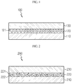
- FIG. 1 is a schematic sectional view illustrating an embodiment of the conventional positive electrode 100 which includes a lithium carbonate-containing primer layer 120 formed between a positive electrode current collector 110 and a positive electrode active material layer 130.
- the primer layer 120 includes lithium carbonate particles 121, and the lithium carbonate particles have substantially the same particle diameter.
- FIG. 2 is a schematic sectional view illustrating the positive electrode 200 which includes a lithium carbonate-containing primer layer 220 formed between a positive electrode current collector 210 and a positive electrode active material layer 230 according to an embodiment of the present disclosure.
- the primer layer 220 includes large lithium carbonate particles 221 having a relatively large particle diameter and small lithium carbonate particles 222 having a relatively small particle diameter.
- the large lithium carbonate particles 221 and the small lithium carbonate particles 222 are spaced apart from each other.
- the large lithium carbonate particles 221 and the small lithium carbonate particles 222 are interconnected to form an interstitial volume which is a space formed by interconnection of particles, and the interstitial volume may function as pores.
- the lithium carbonate particles may be present in an amount of 90-99.9 wt% based on the solid content in the primer layer.
- the content of the lithium carbonate particles is less than the lower limit, electric resistance is increased insufficiently.
- the content of the lithium carbonate particles is larger than the upper limit, bindability among the ingredients or electroconductivity may be insufficient.
- the lithium carbonate particles may have a shape, such as a spherical, elliptical or polygonal shape, but is not limited thereto.
- the terms 'spherical' and 'elliptical' have broad meanings including not only perfect 'spherical' and 'elliptical' shapes but also spherical and elliptical shapes having a dented portion or commonly acceptable levels of spherical and elliptical shapes.
- the lithium carbonate particles have two or more different particle diameters.
- the lithium carbonate particles may have two or more different particle diameter ranges, and in other words, they may include large particles and small particles.
- the term 'particle diameter' refers to a particle diameter D50 which means the particle diameter corresponding 50% on the weight basis in a particle size distribution curve.
- the large lithium carbonate particles may have a particle diameter of 3-15 ⁇ m.
- the particle diameter D50 of the large particles may be 3 ⁇ m or more, 4 ⁇ m or more, or 5 ⁇ m or more, within the above-defined range.
- the particle diameter of the large lithium carbonate particles is larger than the upper limit, the volume of an electrode is increased undesirably.
- the particle diameter of the large lithium carbonate particles is smaller than the lower limit, it is difficult to accomplish the desired effect of the present disclosure, i.e., the effect of interrupting the conductive path of the primer layer, after gas generation occurring at a specific voltage, by reducing the content of a conductive material.
- the large lithium carbonate particles may have a BET specific surface area of 0.4-2.0 m 2 /g.
- the primer layer may have a thickness of 3-15 ⁇ m.
- 'BET specific surface area' refers to the specific surface area determined by the BET method using nitrogen as absorption gas.
- the small lithium carbonate particles may have a particle diameter equal to or larger than 0.1 and less than 3.0 ⁇ m. According to an embodiment of the present disclosure, the small particles may have a particle diameter of 2.5 ⁇ m or less, 2.0 ⁇ m or less, or 1.5 ⁇ m or less, within the above-defined range.
- the small lithium carbonate particles When the small lithium carbonate particles have a particle diameter larger than the upper limit, it takes a long time to attain the overcharge cutoff voltage.
- the small lithium carbonate particles have a particle diameter smaller than the lower limit, the content of a conductive material is increased, thereby making it difficult to accomplish the effect of the present disclosure. It is also difficult to form pores through which lithium ions may be transported smoothly.
- the small lithium carbonate particles may have a BET specific surface area larger than 2.0 m 2 /g and equal to or less than 5.0 m 2 /g.
- the lithium carbonate particles may include the small lithium carbonate particles in an amount of 0.1-200 parts by weight, preferably 50-150 parts by weight, and more preferably 80-120 parts by weight, based on 100 parts by weight of the large lithium carbonate particles.
- the content of the small lithium carbonate particles is larger than the upper limit, the surface area of the particles contained in the primer layer is increased, resulting in a relative decrease in content of the conductive material, thereby providing increased electric resistance.
- the small particles show a higher reaction rate as compared to the large particles.
- the content of the small particles is increased, the amount of vaporized lithium carbonate is increased, and thus the overcharge cutoff voltage may be attained earlier.
- the content of the small particles is less than the lower limit, the time of attainment of overcharge cutoff voltage may be delayed.
- the primer layer may have a porous structure sustained by the lithium carbonate particles.
- the lithium carbonate particles are interconnected and the space formed among the interconnected lithium carbonate particles may function as pores.
- the small lithium carbonate particles may have a particle diameter size with which the particles can enter the space formed by interconnection of the large lithium carbonate particles, i.e., the interstitial volume. Otherwise, the small lithium carbonate particles may have a particle diameter size larger than the space formed by interconnection of the large lithium carbonate particles, i.e., the interstitial volume, but smaller than the particle diameter of the large lithium carbonate particles.
- the conductive material may be present in an amount of 0.1-10 wt% based on the solid content in the primer layer. According to the present disclosure, the required content of the conductive material is reduced as compared to the content thereof in the case of the use of small lithium carbonate particles alone. Thus, the possibility of interruption of the conductive path of the primer layer after the gas generation occurring at a specific voltage is increased.
- the conductive material may be at least one selected from the group consisting of a graphite-based conductive material, carbon black-based conductive material, and metal-based or metal compound-based conductive material.
- the graphite-based conductive material may be at least one of artificial graphite and natural graphite
- the carbon black-based conductive material may be at least one of ketjen black, denka black, thermal black and channel black
- the metal-based or metal compound-based conductive material may be at least one of tin, tin oxide, tin phosphate (SnPO4), titanium oxide, potassium titanate, and perovskite-type materials such as LaSrCoO 3 and LaSrMnO 3 .
- the lithium carbonate particle, conductive material and the binder polymer may be applied onto the positive electrode current collector, after they are dispersed or dissolved in an organic solvent to form a slurry state.
- the solid content in the organic solvent i.e. the content of the lithium carbonate particles, conductive material and binder is not particularly limited, as long as it provides slurry having such a viscosity that the slurry may be applied with ease without rolling-down.
- the organic solvent preferably includes any one selected from the group consisting of N-methyl-2-pyrrolidone (NMP), methoxypropyl acetate, butyl acetate, glycol acid, butyl ester, butyl glycol, methylalkyl polysiloxane, alkyl benzene, propylene glycol, xylene, monophenyl glycol, aralkyl-modified methylalkyl polysiloxane, polyether-modified dimethylpolysiloxane copolymer, polyacrylate solution, alkylbenzene, diisobutyl ketone, organically modified polysiloxane, butanol, isobutanol, modified polyacrylate, modified polyurethane and polysiloxane-modified polymer, or a combination of two or more of them.
- NMP N-methyl-2-pyrrolidone
- methoxypropyl acetate butyl acetate
- glycol acid but
- the positive electrode current collector is formed to have a thickness of 3-500 ⁇ m.
- the positive electrode current collector is not particularly limited, as long as it causes no chemical change in the corresponding battery and has high conductivity.
- Particular examples of the positive electrode current collector may include stainless steel; aluminum; nickel; titanium; baked carbon; copper; stainless steel surface-treated with carbon, nickel, titanium or silver; or the like. It is possible to increase the adhesion of a positive electrode active material by forming fine surface irregularities on the surface of a current collector.
- the positive electrode current collector may have various shapes, such as a film, sheet, foil, net, porous body, foam and a non-woven web body.
- the positive electrode active material contained in the positive electrode active material layer may include, but are not limited to: layered compounds such as lithium cobalt oxide (LiCoO 2 ) and lithium nickel oxide (LiNiO 2 ), or those compounds substituted with one or more transition metals; lithium manganese oxides such as those represented by the chemical formula of Li 1+x Mn 2-x O 4 (wherein x is 0-0.33), LiMnO 3 , LiMn 2 O 3 and LiMnO 2 ; lithium copper oxide (Li 2 CuO 2 ); vanadium oxides such as LiV 3 O 8 , LiFe 3 O 4 , V 2 O 5 or Cu 2 V 2 O 7 ; Ni-site type lithium nickel oxides represented by the chemical formula of LiNi 1-x M x O 2 (wherein M is Co, Mn, Al, Cu, Fe, Mg, B or Ga, and x is 0.01-0.3); lithium manganese composite oxides represented by the chemical formula of LiMn 2-x M x O 2 (wherein M
- the positive electrode active material layer may further include a conductive material, binder polymer and a filler, besides the positive electrode active material.
- the conductive material is added generally in an amount of 1-50 wt% based on the total weight of the mixture including the positive electrode active material.
- the conductive material is not particularly limited, as long as it causes no chemical change in the corresponding battery and has conductivity.
- Particular examples of the conductive material include: graphite, such as natural graphite or artificial graphite; carbon black, such as carbon black, acetylene black, ketjen black, channel black, furnace black, lamp black or thermal black; conductive fibers, such as carbon fibers or metallic fibers; metal powder, such as carbon fluoride, aluminum or nickel powder; conductive whisker, such as zinc oxide or potassium titanate; conductive metal oxide, such as titanium oxide; and conductive materials, such as polyphenylene derivatives.
- the binder polymer is an ingredient which assists binding between the positive electrode active material and the conductive material and binding to the current collector.
- the binder polymer is added in an amount of 1-50 wt% based on the total weight of the mixture including the positive electrode active material.
- binder polymer examples include polyvinylidene fluoride, polyvinyl alcohol, carboxymethyl cellulose (CMC), starch, hydroxypropyl cellulose, regenerated cellulose, polyvinyl pyrrolidone, tetrafluoroethylene, polyethylene, polypropylene, ethylenepropylene-diene terpolymer (EPDM), sulfonated EPDM, styrene butyrene rubber, fluororubber, various copolymers, or the like.
- CMC carboxymethyl cellulose
- EPDM ethylenepropylene-diene terpolymer
- EPDM ethylenepropylene-diene terpolymer
- EPDM ethylenepropylene-diene terpolymer
- sulfonated EPDM styrene butyrene rubber
- fluororubber various copolymers, or the like.
- the filler is an ingredient inhibiting swelling of the positive electrode and is used optionally.
- the filler is not particularly limited, as long as it causes no chemical change in the corresponding battery and is a fibrous material.
- Particular examples of the filler include olefinic polymers, such as polyethylene or polypropylene; and fibrous materials, such as glass fibers or carbon fibers.
- a lithium secondary battery including the above-described positive electrode, a negative electrode (anode), a separator and a lithium salt-containing non-aqueous electrolyte.
- the negative electrode is obtained by applying negative electrode active material slurry containing a negative electrode active material to a negative electrode current collector, followed by drying and pressing.
- the negative electrode active material slurry may further include the above-mentioned conductive material, binder polymer, filler, or the like, if desired.
- the negative electrode current collector is formed to have a thickness of 3-500 ⁇ m.
- the negative electrode current collector is not particularly limited, as long as it causes no chemical change in the corresponding battery and has conductivity.
- Particular examples of the negative electrode current collector may include copper; stainless steel; aluminum; nickel; titanium; baked carbon; copper or stainless steel surface-treated with carbon, nickel, titanium or silver; or the like.
- the positive electrode current collector it is possible to increase the adhesion of a negative electrode active material by forming fine surface irregularities on the surface of a current collector.
- the negative electrode current collector may have various shapes, such as a film, sheet, foil, net, porous body, foam and a non-woven web body.
- the negative electrode active material include: carbon such as non-graphitizable carbon or graphite-based carbon; metal composite oxides, such as Li x Fe 2 O 3 (0 ⁇ x ⁇ 1), Li x WO 2 (0 ⁇ x ⁇ 1), Sn x Me 1-x Me' y O z (Me: Mn, Fe, Pb, Ge; Me' : Al, B, P, Si, elements of Group 1, 2 or 3 in the Periodic Table, halogen; 0 ⁇ x ⁇ 1; 1 ⁇ y ⁇ 3; 1 ⁇ z ⁇ 8); lithium metal; lithium alloy; silicon-based alloy; tin-based alloy; metal oxides, such as AuO, SnO 2 , PbO, PbO 2 , Pb 2 O 3 , Pb 3 O 4 , Sb 2 O 3 , Sb 2 O 4 , Sb 2 O 5 , GeO, GeO 2 , Bi 2 O 3 , Bi 2 O 4 and Bi 2 O 5 ;
- the above-mentioned electrode structure is preferred since LTO itself has low electroconductivity.
- it is preferred to use a spinel type lithium manganese composite oxide represented by the formula of LiNixMn 2-x O 4 (x 0.01-0.6) and having relatively high potential by virtue of the high potential of LTO, as the positive electrode active material.
- the lithium secondary battery includes an electrode assembly having the separator interposed between the positive electrode and the negative electrode, and a lithium salt-containing electrolyte injected thereto.
- the separator is interposed between the positive electrode and the negative electrode.
- An insulating thin film having high ion permeability and mechanical strength is used as the separator.
- the separator generally has a pore diameter of 0.01-10 ⁇ m and a thickness of 5-300 ⁇ m.
- Particular examples of the separator include sheets or nonwoven webs made of olefinic polymers, such as polypropylene having chemical resistance and hydrophobic property; glass fibers or polyethylene, or the like.
- a solid electrolyte such as a polymer
- the solid electrolyte may also function as a separator.
- the lithium salt-containing electrolyte includes an electrolyte and a lithium salt, and the electrolyte includes a non-aqueous organic solvent, organic solid electrolyte, inorganic solid electrolyte, or the like, but is not limited thereto.
- non-aqueous organic solvent examples include aprotic solvents, such as N-methyl-2-pyrrolidone, propylene carbonate, ethylene carbonate, butylene carbonate, dimethyl carbonate, diethyl carbonate, ⁇ -butyrolactone, 1,2-dimethoxyethane, tetrahydroxy franc, 2-methyl tetrahydrofuran, dimethyl sulfoxide, 1,3-dioxolan, formamide, dimethyl formamide, dioxolan, acetonitrile, nitromethane, methyl formate, methyl acetate, triphosphate, trimethoxymethane, dioxolan derivatives, methyl sulforane, 1,3-dimethyl-2-imidazolidione, propylene carbonate derivatives, tetrahydrofuran derivatives, ethers, methyl propionate, ethyl propionate, or the like.
- aprotic solvents such as N-methyl-2-
- organic solid electrolyte may include polyethylene derivatives, polyethylene oxide derivatives, polypropylene oxide derivatives, phosphate polymer, polyagitation lysine, polyester sulfide, polyvinyl alcohol, polyvinylidene fluoride, polymers containing an ionically dissociatable group, or the like.
- the inorganic solid electrolyte may include nitrides, halides and sulfates of Li, such as Li 3 N, Lil, Li 5 NI 2 , Li 3 N-LiI-LiOH, LiSiO 4 , LiSiO 4 -LiI-LiOH, Li 2 SiS 3 , Li 4 SiO 4 , Li 4 SiO 4 -LiI-LiOH and Li 3 PO 4 -Li 2 S-SiS 2 .
- Li such as Li 3 N, Lil, Li 5 NI 2 , Li 3 N-LiI-LiOH, LiSiO 4 , LiSiO 4 -LiI-LiOH, Li 2 SiS 3 , Li 4 SiO 4 , Li 4 SiO 4 -LiI-LiOH and Li 3 PO 4 -Li 2 S-SiS 2 .
- the lithium salt is a material which can be dissolved in the non-aqueous electrolyte with ease, and particular examples thereof include LiCl, LiBr, Lil, LiClO 4 , LiBF 4 , LiB 10 Cl 10 , LiPF 6 , LiCF 3 SO 3 , LiCF 3 CO 2 , LiAsF 6 , LiSbF 6 , LiAlCl 4 , CH 3 SO 3 Li, (CF 3 SO 2 ) 2 NLi, lithium chloroborate, lithium lower aliphatic carboxylate, lithium tetraphenyl borate, imide, or the like.
- the electrolyte may further include pyridine, triethyl phosphite, triethanolamine, cyclic ethers, ethylene diamine, n-glyme, triamide hexaphosphate, nitrobenzene derivatives, sulfur, quinone imine dyes, N-substituted oxazolidinone, N,N-substituted imidazolidine, ethylene glycol dialkyl ether, ammonium salt, pyrrole, 2-methoxyethaol and aluminum trichloride in order to improve the charge/discharge characteristics, flame resistance, or the like.
- the electrolyte may further include a halogen-containing solvent, such as carbon tetrachloride or trifluoroethylene, in order to impart non-combustibility.
- the electrolyte may further include carbon dioxide gas in order to improve the high-temperature storage characteristics.
- the electrolyte may further include fluoro-ethylene carbonate (FEC), propene sultone (PRS), or the like.
- a lithium salt-containing non-aqueous electrolyte by adding a lithium salt, such as LiPF 6 , LiClO 4 , LiBF 4 or LiN(SO 2 CF 3 ) 2 to a mixed solvent containing a cyclic carbonate, such as EC or PC, as a solvent having high dielectric property in combination with a linear carbonate, such as DEC, DMC or EMC, as a solvent having low viscosity.
- a lithium salt such as LiPF 6 , LiClO 4 , LiBF 4 or LiN(SO 2 CF 3 ) 2
- a mixed solvent containing a cyclic carbonate such as EC or PC
- a solvent having high dielectric property in combination with a linear carbonate such as DEC, DMC or EMC
- a battery module including the lithium secondary battery as a unit cell, and a battery pack including the battery module.
- the battery pack may be used as a power source for medium- or large-scale devices requiring high-temperature stability, long cycle characteristics and high rate characteristics.
- Preferred examples of the medium- or large-scale devices include, but are not limited to: power tools driven by the power of an electric motor; electric cars, including electric vehicles (EV), hybrid electric vehicles (HEV), plug-in hybrid electric vehicles (PHEV), or the like; electric two-wheeled vehicles, including E-bikes and E-scooters; electric golf carts; electric power storage systems; or the like.
- electric motor including electric vehicles (EV), hybrid electric vehicles (HEV), plug-in hybrid electric vehicles (PHEV), or the like
- electric two-wheeled vehicles including E-bikes and E-scooters
- electric golf carts electric power storage systems; or the like.
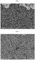
- FIG. 3 is a scanning electron microscopic (SEM) image illustrating the section of the primer layer formed in this Example. Referring to FIG. 3 , it can be seen that the primer layer has a porous structure wherein the space formed among the lithium carbonate particles function as pores.
- LiCoO 2 having a D50 of about 15-20 ⁇ m as a positive electrode active material, Super P as a conductive material and polyvinylidene fluoride as a binder polymer were mixed at a weight ratio of 92:4:4, and N-methyl pyrrolidone (NMP) was added thereto to prepare positive electrode active material slurry.
- the prepared positive electrode slurry was applied onto the aluminum positive electrode current collector having the primer layer, and then dried in a vacuum oven at 120°C to obtain a positive electrode including the positive electrode current collector, positive electrode active material layer and the primer layer formed between the positive electrode current collector and the positive electrode active material layer.
- MCMB mesocarbon microbeads
- Super-P and PVdF were used as a conductive material and a binder, respectively, and the ingredients were mixed at a ratio (weight ratio) of 92:2:6 and dispersed in NMP to prepare negative electrode active material slurry. Then, the negative electrode active material slurry was applied to a copper foil current collector, followed by drying, to obtain a negative electrode.
- a polyethylene separator was interposed between the obtained positive electrode and negative electrode to provide an electrode assembly.
- the electrode assembly was introduced to a pouch type casing and electrode leads were connected thereto. Then, a solution containing ethylene carbonate (EC) and dimethyl carbonate (DMC) at a volume ratio of 1:1 and including 1M LiPF 6 dissolved therein was injected as an electrolyte, followed by sealing, to finish a lithium secondary battery.
- EC ethylene carbonate
- DMC dimethyl carbonate
- a positive electrode and a lithium secondary battery were obtained in the same manner as Example 1, except that 100 g of large lithium carbonate particles, i.e., lithium carbonate particles having a particle diameter of 5.0 ⁇ m were used instead of the two types of lithium carbonate particles when preparing slurry for forming a primer layer.
- FIG. 4 is a SEM image illustrating the section of the primer layer formed in Comparative Example 1.
- a positive electrode and a lithium secondary battery were obtained in the same manner as Example 1, except that 100 g of small lithium carbonate particles, i.e., lithium carbonate particles having a particle diameter of 2.0 ⁇ m were used instead of the two types of lithium carbonate particles when preparing slurry for forming a primer layer.
- FIG. 5 is a SEM image illustrating the section of the primer layer formed in Comparative Example 2.
- Test Example 1 Overcharge Test Result
- a primer layer generating gas when a specific voltage was attained causes an increase in resistance due to the gas generation of the primer layer in an overcharged state, resulting in application of overvoltage to attain the overcharge cutoff voltage, 6.4V.
- the conductive path is interrupted with high possibility upon the gas generation, and thus it is possible to attain the overcharge cutoff voltage earlier.
- a gas-generating material is realized in a bimodal type in the primer layer so that the overcharge cutoff voltage may be attained in a safe region and the battery may have DC (direct current) resistance equal to that of the battery having no primer layer, while reducing the absolute amount of the conductive material.
- the overcharge test was carried out in a two-step mode.
- a state of SOC 100 was made at room temperature (25°C) under ambient pressure in a CC/CV (constant current/constant voltage) condition of 0.33C/4.25V, wherein the cut-off current was 0.05 C (the first step: SOC 100 setting).
- charging was started at room temperature under ambient pressure in a CC (1C-rate) condition from SOC 100 to carry out the overcharge test, and then was terminated after 1 hour or when the voltage was 1.5 times of the maximum voltage to cause overcharge (the second step: overcharge).
- the second step overcharge
- FIG. 6 is a graph illustrating the overcharge test results of the lithium secondary batteries according to Example 1 and Comparative Examples 1 and 2.
- Example 1 attains the overcharge cutoff voltage at the earliest time.
- Test Example 2 Results of Measurement of Change in Volume and Gas Generation Amounts upon Overcharge
- the change in volume before/after overcharge could be calculated by using the weight measurement of each battery determined through a balance in a water tank before and after overcharge and the change in volume of water in the water tank.
- Each battery has the same weight before and after overcharge, but gas is generated in the battery after overcharge.
- the weight of each battery is measured in the water tank, its weight is reduced slightly as compared to the battery before overcharge due to the effect of buoyancy.
- the exterior part of the battery was taped tightly so that water may not be infiltrated into the battery.
- Test Example 3 Results of Measurement of Resistance in Positive Electrode and Battery
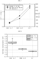
- FIG. 8 is a graph illustrating the interfacial resistance of the primer layer of each of the positive electrodes according to Example 1 and Comparative Examples 1 and 2
- FIG. 9 is a graph illustrating the resistance of each of the lithium secondary batteries according to Example 1 and Comparative Examples 1 and 2.
- the interfacial resistance of the primer layer of each positive electrode was determined by using an electrode resistance measuring system (available from HIOKI, Model name: XF-074). After the measurement, it can be seen that Example 1 shows the lowest resistance value.
- Example 1 shows the lowest resistance value as compared to Comparative Examples.
Landscapes
- Chemical & Material Sciences (AREA)
- Chemical Kinetics & Catalysis (AREA)
- Electrochemistry (AREA)
- General Chemical & Material Sciences (AREA)
- Engineering & Computer Science (AREA)
- Materials Engineering (AREA)
- Manufacturing & Machinery (AREA)
- Composite Materials (AREA)
- Organic Chemistry (AREA)
- Inorganic Chemistry (AREA)
- Battery Electrode And Active Subsutance (AREA)
- Secondary Cells (AREA)
Abstract
Description
- The present application claims priority to Korean Patent Application No.
10-2017-0094550 filed on July 26, 2017 10-2018-0086694 filed on July 25, 2018 - As electronic, communication and computer industries have been developed rapidly, downsizing, lightening and high functionalization of instruments have been required. In addition, as the portable electronic appliances, such as camcorders, cellular phones and notebook PCs, have been used generally, batteries having a low weight, showing a long service life and having high reliability have been increasingly in demand. Particularly, since the rechargeable lithium secondary batteries have an energy density per unit weight 3 times higher than that of the conventional lead storage battery, nickelcadmium battery, nickel-metal hydride battery, nickel-zinc battery, or the like, and allow rapid charging, research and development of them have been conducted actively in Korea and the foreign countries.
- Recently, some technologies, such as high-capacity active materials, thin separators and high-voltage driving, have been further developed in order to provide lithium secondary batteries with high energy density and low cost. Under these circumstances, overcharging becomes a serious problem, and thus it is required to solve the ignition and explosion issues in an overcharged state.
- To solve this, there has been an attempt to incorporate lithium carbonate (Li2CO3) known to generate gas at about 5.0V in order to increase positive electrode resistance significantly so that the overcharge cut-off voltage may be attained.
- However, according to the above-mentioned attempt, gas generation from lithium carbonate may not be sufficient or positive electrode resistance may not be increased significantly against desired expectations, and thus it takes a long time to attain the overcharge cutoff voltage. Therefore, in this case, there is a problem in that battery safety cannot be ensured sufficiently.
- The present disclosure is designed to solve the problems of the related art, and therefore the present disclosure is directed to providing a positive electrode for a lithium secondary battery which ensures the safety of a lithium secondary battery in an overcharged state.
- The present disclosure is also directed to providing a lithium secondary battery including the positive electrode.
- According to the first embodiment of the present disclosure, there is provided a positive electrode (cathode) for a lithium secondary battery which includes: a positive electrode current collector; a positive electrode active material layer; and a primer layer formed between the positive electrode current collector and the positive electrode active material layer, wherein the primer layer includes lithium carbonate (Li2CO3) particles having two or more different particle diameters, a binder polymer and a conductive material.
- According to the second embodiment of the present disclosure, there is provided the positive electrode for a lithium secondary battery as defined in the first embodiment, wherein the lithium carbonate particles may be present in an amount of 90-99.9 wt% based on the solid content in the primer layer.
- According to the third embodiment of the present disclosure, there is provided the positive electrode for a lithium secondary battery as defined in the first or the second embodiment, wherein the lithium carbonate particles may include large lithium carbonate particles and small lithium carbonate particles.
- According to the fourth embodiment of the present disclosure, there is provided the positive electrode for a lithium secondary battery as defined in the third embodiment, wherein the large lithium carbonate particles have a particle diameter of 3-15 µm and the small lithium carbonate particles have a particle diameter equal to or larger than 0.1 µm and less than 3 µm.
- According to the fifth embodiment of the present disclosure, there is provided the positive electrode for a lithium secondary battery as defined in the third or the fourth embodiment, wherein the small lithium carbonate particles may be present in an amount of 80-120 parts by weight based on 100 parts by weight of the large lithium carbonate particles.
- According to the sixth embodiment of the present disclosure, there is provided the positive electrode for a lithium secondary battery as defined in any one of the first to the fifth embodiments, wherein the primer layer has a thickness of 3-15 µm.
- According to the seventh embodiment of the present disclosure, there is provided the positive electrode for a lithium secondary battery as defined in any one of the third to the fifth embodiments, wherein the small lithium carbonate particles may be larger than the diameter of the interstitial volume which is a space formed by interconnection of the large lithium carbonate particles but may have a smaller particle diameter size as compared to the large lithium carbonate particles.
- According to the eighth embodiment of the present disclosure, there is provided the positive electrode for a lithium secondary battery as defined in any one of the first to the seventh embodiments, wherein the space formed among the lithium carbonate particles may function as pores in the primer layer.
- According to the ninth embodiment of the present disclosure, there is provided the positive electrode for a lithium secondary battery as defined in any one of the first to the eighth embodiments, wherein the primer layer may be porous.
- According to the tenth embodiment of the present disclosure, there is provided a lithium secondary battery including the positive electrode for a lithium secondary battery as defined in any one of the first to the ninth embodiments.
- According to an embodiment of the present disclosure, there is provided a lithium secondary battery which attains the overcharge cutoff voltage rapidly by virtue of the gas generated between the positive electrode current collector and the positive electrode active material layer, in an overcharged state. Thus, it is possible to ensure the safety of the lithium secondary battery.
- According to another embodiment of the present disclosure, there is provided a lithium secondary battery having improved safety by virtue of a decrease in time required to attain the overcharge cutoff voltage.
- According to still another embodiment of the present disclosure, there is provided a lithium secondary battery which ensures maximized capacity through the minimization of the volume occupied by the primer layer for gas generation.
- The accompanying drawings illustrate a preferred embodiment of the present disclosure and together with the foregoing disclosure, serve to provide further understanding of the technical features of the present disclosure, and thus, the present disclosure is not construed as being limited to the drawing.
-
FIG. 1 is a schematic sectional view illustrating the positive electrode to be improved by the present disclosure. -
FIG. 2 is a schematic sectional view illustrating the positive electrode according to an embodiment of the present disclosure. -
FIG. 3 is a scanning electron microscopic (SEM) image illustrating the section of the primer layer according to Example 1. -
FIG. 4 is a scanning electron microscopic (SEM) image illustrating the section of the primer layer according to Comparative Example 1. -
FIG. 5 is a scanning electron microscopic (SEM) image illustrating the section of the primer layer according to Comparative Example 2. -
FIG. 6 is a graph illustrating the overcharge test results of the lithium secondary batteries according to Example 1 and Comparative Examples 1 and 2. -
FIG. 7 is a graph illustrating the variations in volume and gas generation of the lithium secondary batteries according to Example 1 and Comparative Examples 1 and 2 during the overcharge test thereof. -
FIG. 8 is a graph illustrating the interfacial resistance of the primer layer of each of the positive electrodes according to Example 1 and Comparative Examples 1 and 2. -
FIG. 9 is a graph illustrating the resistance of each of the lithium secondary batteries according to Example 1 and Comparative Examples 1 and 2. - Hereinafter, preferred embodiments of the present disclosure will be described in detail.
- It should be understood that the terms used in the specification and the appended claims should not be construed as limited to general and dictionary meanings, but interpreted based on the meanings and concepts corresponding to technical aspects of the present disclosure on the basis of the principle that the inventor is allowed to define terms appropriately for the best explanation.
- In one aspect of the present disclosure, there is provided a positive electrode for a lithium secondary battery which includes: a positive electrode current collector; a positive electrode active material layer; and a primer layer formed between the positive electrode current collector and the positive electrode active material layer, wherein the primer layer includes lithium carbonate (Li2CO3) particles having two or more different particle diameters, a binder polymer and a conductive material, and the primer layer substantially includes no positive electrode active material.
- Hereinafter, the present disclosure will be explained with reference to
FIG. 1 and FIG. 2 . -
FIG. 1 is a schematic sectional view illustrating an embodiment of the conventionalpositive electrode 100 which includes a lithium carbonate-containingprimer layer 120 formed between a positiveelectrode current collector 110 and a positive electrodeactive material layer 130. - In
FIG. 1 , theprimer layer 120 includeslithium carbonate particles 121, and the lithium carbonate particles have substantially the same particle diameter. - Meanwhile,
FIG. 2 is a schematic sectional view illustrating thepositive electrode 200 which includes a lithium carbonate-containingprimer layer 220 formed between a positive electrodecurrent collector 210 and a positive electrodeactive material layer 230 according to an embodiment of the present disclosure. As shown inFIG. 2 , theprimer layer 220 includes largelithium carbonate particles 221 having a relatively large particle diameter and smalllithium carbonate particles 222 having a relatively small particle diameter. InFIG. 2 , the largelithium carbonate particles 221 and the smalllithium carbonate particles 222 are spaced apart from each other. However, according to a preferred embodiment, the largelithium carbonate particles 221 and the smalllithium carbonate particles 222 are interconnected to form an interstitial volume which is a space formed by interconnection of particles, and the interstitial volume may function as pores. - The lithium carbonate particles may be present in an amount of 90-99.9 wt% based on the solid content in the primer layer. When the content of the lithium carbonate particles is less than the lower limit, electric resistance is increased insufficiently. When the content of the lithium carbonate particles is larger than the upper limit, bindability among the ingredients or electroconductivity may be insufficient.
- The lithium carbonate particles may have a shape, such as a spherical, elliptical or polygonal shape, but is not limited thereto. In addition, the terms 'spherical' and 'elliptical' have broad meanings including not only perfect 'spherical' and 'elliptical' shapes but also spherical and elliptical shapes having a dented portion or commonly acceptable levels of spherical and elliptical shapes.
- The lithium carbonate particles have two or more different particle diameters. For example, the lithium carbonate particles may have two or more different particle diameter ranges, and in other words, they may include large particles and small particles. As used herein, the term 'particle diameter' refers to a particle diameter D50 which means the particle diameter corresponding 50% on the weight basis in a particle size distribution curve.
- The large lithium carbonate particles may have a particle diameter of 3-15 µm. According to an embodiment of the present disclosure, the particle diameter D50 of the large particles may be 3 µm or more, 4 µm or more, or 5 µm or more, within the above-defined range. When the particle diameter of the large lithium carbonate particles is larger than the upper limit, the volume of an electrode is increased undesirably. When the particle diameter of the large lithium carbonate particles is smaller than the lower limit, it is difficult to accomplish the desired effect of the present disclosure, i.e., the effect of interrupting the conductive path of the primer layer, after gas generation occurring at a specific voltage, by reducing the content of a conductive material. For example, the large lithium carbonate particles may have a BET specific surface area of 0.4-2.0 m2/g.
- Meanwhile, the primer layer may have a thickness of 3-15 µm.
- As used herein, the term 'BET specific surface area' refers to the specific surface area determined by the BET method using nitrogen as absorption gas.
- The small lithium carbonate particles may have a particle diameter equal to or larger than 0.1 and less than 3.0 µm. According to an embodiment of the present disclosure, the small particles may have a particle diameter of 2.5 µm or less, 2.0 µm or less, or 1.5 µm or less, within the above-defined range. When the small lithium carbonate particles have a particle diameter larger than the upper limit, it takes a long time to attain the overcharge cutoff voltage. When the small lithium carbonate particles have a particle diameter smaller than the lower limit, the content of a conductive material is increased, thereby making it difficult to accomplish the effect of the present disclosure. It is also difficult to form pores through which lithium ions may be transported smoothly. For example, the small lithium carbonate particles may have a BET specific surface area larger than 2.0 m2/g and equal to or less than 5.0 m2/g.
- The lithium carbonate particles may include the small lithium carbonate particles in an amount of 0.1-200 parts by weight, preferably 50-150 parts by weight, and more preferably 80-120 parts by weight, based on 100 parts by weight of the large lithium carbonate particles. When the content of the small lithium carbonate particles is larger than the upper limit, the surface area of the particles contained in the primer layer is increased, resulting in a relative decrease in content of the conductive material, thereby providing increased electric resistance. In addition, the small particles show a higher reaction rate as compared to the large particles. Thus, as the content of the small particles is increased, the amount of vaporized lithium carbonate is increased, and thus the overcharge cutoff voltage may be attained earlier. On the other hand, when the content of the small particles is less than the lower limit, the time of attainment of overcharge cutoff voltage may be delayed.
- The primer layer may have a porous structure sustained by the lithium carbonate particles. In other words, the lithium carbonate particles are interconnected and the space formed among the interconnected lithium carbonate particles may function as pores. In addition, the small lithium carbonate particles may have a particle diameter size with which the particles can enter the space formed by interconnection of the large lithium carbonate particles, i.e., the interstitial volume. Otherwise, the small lithium carbonate particles may have a particle diameter size larger than the space formed by interconnection of the large lithium carbonate particles, i.e., the interstitial volume, but smaller than the particle diameter of the large lithium carbonate particles.
- The conductive material may be present in an amount of 0.1-10 wt% based on the solid content in the primer layer. According to the present disclosure, the required content of the conductive material is reduced as compared to the content thereof in the case of the use of small lithium carbonate particles alone. Thus, the possibility of interruption of the conductive path of the primer layer after the gas generation occurring at a specific voltage is increased.
- The conductive material may be at least one selected from the group consisting of a graphite-based conductive material, carbon black-based conductive material, and metal-based or metal compound-based conductive material. Herein, the graphite-based conductive material may be at least one of artificial graphite and natural graphite, the carbon black-based conductive material may be at least one of ketjen black, denka black, thermal black and channel black, and the metal-based or metal compound-based conductive material may be at least one of tin, tin oxide, tin phosphate (SnPO4), titanium oxide, potassium titanate, and perovskite-type materials such as LaSrCoO3 and LaSrMnO3.
- The lithium carbonate particle, conductive material and the binder polymer may be applied onto the positive electrode current collector, after they are dispersed or dissolved in an organic solvent to form a slurry state. Herein, the solid content in the organic solvent, i.e. the content of the lithium carbonate particles, conductive material and binder is not particularly limited, as long as it provides slurry having such a viscosity that the slurry may be applied with ease without rolling-down. In addition, the organic solvent preferably includes any one selected from the group consisting of N-methyl-2-pyrrolidone (NMP), methoxypropyl acetate, butyl acetate, glycol acid, butyl ester, butyl glycol, methylalkyl polysiloxane, alkyl benzene, propylene glycol, xylene, monophenyl glycol, aralkyl-modified methylalkyl polysiloxane, polyether-modified dimethylpolysiloxane copolymer, polyacrylate solution, alkylbenzene, diisobutyl ketone, organically modified polysiloxane, butanol, isobutanol, modified polyacrylate, modified polyurethane and polysiloxane-modified polymer, or a combination of two or more of them.
- In general, the positive electrode current collector is formed to have a thickness of 3-500 µm. The positive electrode current collector is not particularly limited, as long as it causes no chemical change in the corresponding battery and has high conductivity. Particular examples of the positive electrode current collector may include stainless steel; aluminum; nickel; titanium; baked carbon; copper; stainless steel surface-treated with carbon, nickel, titanium or silver; or the like. It is possible to increase the adhesion of a positive electrode active material by forming fine surface irregularities on the surface of a current collector. The positive electrode current collector may have various shapes, such as a film, sheet, foil, net, porous body, foam and a non-woven web body.
- Particular examples of the positive electrode active material contained in the positive electrode active material layer may include, but are not limited to: layered compounds such as lithium cobalt oxide (LiCoO2) and lithium nickel oxide (LiNiO2), or those compounds substituted with one or more transition metals; lithium manganese oxides such as those represented by the chemical formula of Li1+xMn2-xO4 (wherein x is 0-0.33), LiMnO3, LiMn2O3 and LiMnO2; lithium copper oxide (Li2CuO2); vanadium oxides such as LiV3O8, LiFe3O4, V2O5 or Cu2V2O7; Ni-site type lithium nickel oxides represented by the chemical formula of LiNi1-xMxO2 (wherein M is Co, Mn, Al, Cu, Fe, Mg, B or Ga, and x is 0.01-0.3); lithium manganese composite oxides represented by the chemical formula of LiMn2-xMxO2 (wherein M = Co, Ni, Fe, Cr, Zn or Ta, and x = 0.01-0.1) or Li2Mn3MO8 (wherein M = Fe, Co, Ni, Cu or Zn); spinel type lithium manganese composite oxides represented by the chemical formula of LiNixMn2-xO4 (x = 0.01-0.6); LiMn2O4 in which Li is partially substituted with an alkaline earth metal ion; disulfide compounds; Fe2(MoO4)3; or the like.
- Meanwhile, the positive electrode active material layer may further include a conductive material, binder polymer and a filler, besides the positive electrode active material.
- Herein, the conductive material is added generally in an amount of 1-50 wt% based on the total weight of the mixture including the positive electrode active material. The conductive material is not particularly limited, as long as it causes no chemical change in the corresponding battery and has conductivity. Particular examples of the conductive material include: graphite, such as natural graphite or artificial graphite; carbon black, such as carbon black, acetylene black, ketjen black, channel black, furnace black, lamp black or thermal black; conductive fibers, such as carbon fibers or metallic fibers; metal powder, such as carbon fluoride, aluminum or nickel powder; conductive whisker, such as zinc oxide or potassium titanate; conductive metal oxide, such as titanium oxide; and conductive materials, such as polyphenylene derivatives.
- In addition, the binder polymer is an ingredient which assists binding between the positive electrode active material and the conductive material and binding to the current collector. In general, the binder polymer is added in an amount of 1-50 wt% based on the total weight of the mixture including the positive electrode active material. Particular examples of the binder polymer include polyvinylidene fluoride, polyvinyl alcohol, carboxymethyl cellulose (CMC), starch, hydroxypropyl cellulose, regenerated cellulose, polyvinyl pyrrolidone, tetrafluoroethylene, polyethylene, polypropylene, ethylenepropylene-diene terpolymer (EPDM), sulfonated EPDM, styrene butyrene rubber, fluororubber, various copolymers, or the like.
- Further, the filler is an ingredient inhibiting swelling of the positive electrode and is used optionally. The filler is not particularly limited, as long as it causes no chemical change in the corresponding battery and is a fibrous material. Particular examples of the filler include olefinic polymers, such as polyethylene or polypropylene; and fibrous materials, such as glass fibers or carbon fibers.
- In another aspect of the present disclosure, there is provided a lithium secondary battery including the above-described positive electrode, a negative electrode (anode), a separator and a lithium salt-containing non-aqueous electrolyte.
- The negative electrode is obtained by applying negative electrode active material slurry containing a negative electrode active material to a negative electrode current collector, followed by drying and pressing. The negative electrode active material slurry may further include the above-mentioned conductive material, binder polymer, filler, or the like, if desired.
- In general, the negative electrode current collector is formed to have a thickness of 3-500 µm. The negative electrode current collector is not particularly limited, as long as it causes no chemical change in the corresponding battery and has conductivity. Particular examples of the negative electrode current collector may include copper; stainless steel; aluminum; nickel; titanium; baked carbon; copper or stainless steel surface-treated with carbon, nickel, titanium or silver; or the like. As mentioned earlier with reference to the positive electrode current collector, it is possible to increase the adhesion of a negative electrode active material by forming fine surface irregularities on the surface of a current collector. The negative electrode current collector may have various shapes, such as a film, sheet, foil, net, porous body, foam and a non-woven web body.
- Particular examples of the negative electrode active material include: carbon such as non-graphitizable carbon or graphite-based carbon; metal composite oxides, such as LixFe2O3(0 ≤ x ≤ 1), LixWO2(0 ≤ x ≤ 1), SnxMe1-xMe'yOz (Me: Mn, Fe, Pb, Ge; Me' : Al, B, P, Si, elements of
Group - According to an embodiment, when using lithium titanium oxide (LTO) as the negative electrode active material, the above-mentioned electrode structure is preferred since LTO itself has low electroconductivity. In addition, in this case, it is preferred to use a spinel type lithium manganese composite oxide represented by the formula of LiNixMn2-xO4 (x = 0.01-0.6) and having relatively high potential by virtue of the high potential of LTO, as the positive electrode active material.
- In addition, the lithium secondary battery includes an electrode assembly having the separator interposed between the positive electrode and the negative electrode, and a lithium salt-containing electrolyte injected thereto.
- The separator is interposed between the positive electrode and the negative electrode. An insulating thin film having high ion permeability and mechanical strength is used as the separator. The separator generally has a pore diameter of 0.01-10 µm and a thickness of 5-300 µm. Particular examples of the separator include sheets or nonwoven webs made of olefinic polymers, such as polypropylene having chemical resistance and hydrophobic property; glass fibers or polyethylene, or the like. When a solid electrolyte, such as a polymer, is used as electrolyte, the solid electrolyte may also function as a separator.
- The lithium salt-containing electrolyte includes an electrolyte and a lithium salt, and the electrolyte includes a non-aqueous organic solvent, organic solid electrolyte, inorganic solid electrolyte, or the like, but is not limited thereto.
- Particular examples of the non-aqueous organic solvent include aprotic solvents, such as N-methyl-2-pyrrolidone, propylene carbonate, ethylene carbonate, butylene carbonate, dimethyl carbonate, diethyl carbonate, γ-butyrolactone, 1,2-dimethoxyethane, tetrahydroxy franc, 2-methyl tetrahydrofuran, dimethyl sulfoxide, 1,3-dioxolan, formamide, dimethyl formamide, dioxolan, acetonitrile, nitromethane, methyl formate, methyl acetate, triphosphate, trimethoxymethane, dioxolan derivatives, methyl sulforane, 1,3-dimethyl-2-imidazolidione, propylene carbonate derivatives, tetrahydrofuran derivatives, ethers, methyl propionate, ethyl propionate, or the like.
- Particular examples of the organic solid electrolyte may include polyethylene derivatives, polyethylene oxide derivatives, polypropylene oxide derivatives, phosphate polymer, polyagitation lysine, polyester sulfide, polyvinyl alcohol, polyvinylidene fluoride, polymers containing an ionically dissociatable group, or the like.
- Particular examples of the inorganic solid electrolyte may include nitrides, halides and sulfates of Li, such as Li3N, Lil, Li5NI2, Li3N-LiI-LiOH, LiSiO4, LiSiO4-LiI-LiOH, Li2SiS3, Li4SiO4, Li4SiO4-LiI-LiOH and Li3PO4-Li2S-SiS2.
- The lithium salt is a material which can be dissolved in the non-aqueous electrolyte with ease, and particular examples thereof include LiCl, LiBr, Lil, LiClO4, LiBF4, LiB10Cl10, LiPF6, LiCF3SO3, LiCF3CO2, LiAsF6, LiSbF6, LiAlCl4, CH3SO3Li, (CF3SO2)2NLi, lithium chloroborate, lithium lower aliphatic carboxylate, lithium tetraphenyl borate, imide, or the like.
- In addition, the electrolyte may further include pyridine, triethyl phosphite, triethanolamine, cyclic ethers, ethylene diamine, n-glyme, triamide hexaphosphate, nitrobenzene derivatives, sulfur, quinone imine dyes, N-substituted oxazolidinone, N,N-substituted imidazolidine, ethylene glycol dialkyl ether, ammonium salt, pyrrole, 2-methoxyethaol and aluminum trichloride in order to improve the charge/discharge characteristics, flame resistance, or the like. Optionally, the electrolyte may further include a halogen-containing solvent, such as carbon tetrachloride or trifluoroethylene, in order to impart non-combustibility. The electrolyte may further include carbon dioxide gas in order to improve the high-temperature storage characteristics. In addition, the electrolyte may further include fluoro-ethylene carbonate (FEC), propene sultone (PRS), or the like.
- According to a preferred embodiment, it is possible to prepare a lithium salt-containing non-aqueous electrolyte by adding a lithium salt, such as LiPF6, LiClO4, LiBF4 or LiN(SO2CF3)2 to a mixed solvent containing a cyclic carbonate, such as EC or PC, as a solvent having high dielectric property in combination with a linear carbonate, such as DEC, DMC or EMC, as a solvent having low viscosity.
- In still another aspect, there are provided a battery module including the lithium secondary battery as a unit cell, and a battery pack including the battery module.
- The battery pack may be used as a power source for medium- or large-scale devices requiring high-temperature stability, long cycle characteristics and high rate characteristics.
- Preferred examples of the medium- or large-scale devices include, but are not limited to: power tools driven by the power of an electric motor; electric cars, including electric vehicles (EV), hybrid electric vehicles (HEV), plug-in hybrid electric vehicles (PHEV), or the like; electric two-wheeled vehicles, including E-bikes and E-scooters; electric golf carts; electric power storage systems; or the like.
- Hereinafter, the present disclosure will be explained in detail with reference to Examples. However, the scope of the present disclosure is not limited to the exemplary embodiments set forth therein.
- First, 2 g of polyvinylidene fluoride as a binder polymer was dissolved in N-methyl pyrrolidone. Then, lithium carbonate (Li2CO3) particles including 50 g of small lithium carbonate particles having a particle diameter of 2.0 µm and 50 g of large lithium carbonate particles having a particle diameter of 5.0 µm, and 4 g of Super-P as a conductive material were added thereto to prepare slurry for forming a primer layer. After the slurry was coated onto an aluminum positive electrode current collector, it was dried in a vacuum oven at 120°C to form a primer layer with a loading amount of 0.03 g/m2. The resultant primer layer had a thickness of 9 µm.
-
FIG. 3 is a scanning electron microscopic (SEM) image illustrating the section of the primer layer formed in this Example. Referring toFIG. 3 , it can be seen that the primer layer has a porous structure wherein the space formed among the lithium carbonate particles function as pores. - Next, LiCoO2 having a D50 of about 15-20 µm as a positive electrode active material, Super P as a conductive material and polyvinylidene fluoride as a binder polymer were mixed at a weight ratio of 92:4:4, and N-methyl pyrrolidone (NMP) was added thereto to prepare positive electrode active material slurry. The prepared positive electrode slurry was applied onto the aluminum positive electrode current collector having the primer layer, and then dried in a vacuum oven at 120°C to obtain a positive electrode including the positive electrode current collector, positive electrode active material layer and the primer layer formed between the positive electrode current collector and the positive electrode active material layer.
- Meanwhile, mesocarbon microbeads (MCMB) were used as a negative electrode active material and Super-P and PVdF were used as a conductive material and a binder, respectively, and the ingredients were mixed at a ratio (weight ratio) of 92:2:6 and dispersed in NMP to prepare negative electrode active material slurry. Then, the negative electrode active material slurry was applied to a copper foil current collector, followed by drying, to obtain a negative electrode.
- A polyethylene separator was interposed between the obtained positive electrode and negative electrode to provide an electrode assembly. The electrode assembly was introduced to a pouch type casing and electrode leads were connected thereto. Then, a solution containing ethylene carbonate (EC) and dimethyl carbonate (DMC) at a volume ratio of 1:1 and including 1M LiPF6 dissolved therein was injected as an electrolyte, followed by sealing, to finish a lithium secondary battery.
- A positive electrode and a lithium secondary battery were obtained in the same manner as Example 1, except that 100 g of large lithium carbonate particles, i.e., lithium carbonate particles having a particle diameter of 5.0 µm were used instead of the two types of lithium carbonate particles when preparing slurry for forming a primer layer.
-
FIG. 4 is a SEM image illustrating the section of the primer layer formed in Comparative Example 1. - A positive electrode and a lithium secondary battery were obtained in the same manner as Example 1, except that 100 g of small lithium carbonate particles, i.e., lithium carbonate particles having a particle diameter of 2.0 µm were used instead of the two types of lithium carbonate particles when preparing slurry for forming a primer layer.
-
FIG. 5 is a SEM image illustrating the section of the primer layer formed in Comparative Example 2. - A primer layer generating gas when a specific voltage was attained causes an increase in resistance due to the gas generation of the primer layer in an overcharged state, resulting in application of overvoltage to attain the overcharge cutoff voltage, 6.4V. Basically, as the absolute amount of the conductive material in the primer layer is decreased, the conductive path is interrupted with high possibility upon the gas generation, and thus it is possible to attain the overcharge cutoff voltage earlier. However, in this case, there is a problem of an increase in the resistance of a battery. To solve this, a gas-generating material is realized in a bimodal type in the primer layer so that the overcharge cutoff voltage may be attained in a safe region and the battery may have DC (direct current) resistance equal to that of the battery having no primer layer, while reducing the absolute amount of the conductive material.
- The overcharge test was carried out in a two-step mode. First, a state of
SOC 100 was made at room temperature (25°C) under ambient pressure in a CC/CV (constant current/constant voltage) condition of 0.33C/4.25V, wherein the cut-off current was 0.05 C (the first step:SOC 100 setting). Then, charging was started at room temperature under ambient pressure in a CC (1C-rate) condition fromSOC 100 to carry out the overcharge test, and then was terminated after 1 hour or when the voltage was 1.5 times of the maximum voltage to cause overcharge (the second step: overcharge). There is no limitation in size of specimens. -
FIG. 6 is a graph illustrating the overcharge test results of the lithium secondary batteries according to Example 1 and Comparative Examples 1 and 2. - It can be seen that Example 1 attains the overcharge cutoff voltage at the earliest time.
- A change in volume of each battery before/after overcharge and gas generation amount when the overcharge cutoff voltage was attained were determined. The results are shown in
FIG. 7 and Table 1. - Herein, the change in volume before/after overcharge could be calculated by using the weight measurement of each battery determined through a balance in a water tank before and after overcharge and the change in volume of water in the water tank. Each battery has the same weight before and after overcharge, but gas is generated in the battery after overcharge. Thus, when the weight of each battery is measured in the water tank, its weight is reduced slightly as compared to the battery before overcharge due to the effect of buoyancy. When using the difference in weight of the battery and the change in volume of water in the water tank, it is possible to determine the change in volume of the battery. When the battery was immersed in the water of the water tank, the exterior part of the battery was taped tightly so that water may not be infiltrated into the battery.
- Meanwhile, the gas generation amount was determined by gas chromatography analysis. The results show amounts of CO and CO2 gases.
[Table 1] Ex. 1 Comp. Ex. 1 Comp. Ex. 2 Change in volume (mL) 1.151 0.956 1.008 Gas generation amount (µL) CO 708 474 654 CO2 1,780 951 1,220 CO + CO2 2,488 1,425 1,874 -
FIG. 8 is a graph illustrating the interfacial resistance of the primer layer of each of the positive electrodes according to Example 1 and Comparative Examples 1 and 2, andFIG. 9 is a graph illustrating the resistance of each of the lithium secondary batteries according to Example 1 and Comparative Examples 1 and 2. - The interfacial resistance of the primer layer of each positive electrode was determined by using an electrode resistance measuring system (available from HIOKI, Model name: XF-074). After the measurement, it can be seen that Example 1 shows the lowest resistance value.
- In addition, to measure the resistance of a lithium secondary battery, discharge was carried out for 10 s at 3C-rate in the state of SOC 50%. It was possible to calculate the DC resistance of the battery from the change in voltage at this time. As a result, it can be seen that Example 1 shows the lowest resistance value as compared to Comparative Examples.
- The present disclosure has been described in detail. However, it should be understood that the detailed description and specific examples, while indicating preferred embodiments of the disclosure, are given by way of illustration only, since various changes and modifications within the scope of the disclosure will become apparent to those skilled in the art from this detailed description.
Claims (9)
- A positive electrode for a lithium secondary battery which comprises: a positive electrode current collector; a positive electrode active material layer; and a primer layer formed between the positive electrode current collector and the positive electrode active material layer, wherein the primer layer comprises lithium carbonate (Li2CO3) particles having two or more different particle diameters, a binder polymer and a conductive material.
- The positive electrode for a lithium secondary battery according claim 1, wherein the lithium carbonate particles are present in an amount of 90-99.9 wt% based on the solid content in the primer layer.
- The positive electrode for a lithium secondary battery according claim 1, wherein the lithium carbonate particles comprise large lithium carbonate particles and small lithium carbonate particles.
- The positive electrode for a lithium secondary battery according claim 3, wherein the large lithium carbonate particles have a particle diameter of 3-15 µm and the small lithium carbonate particles have a particle diameter equal to or larger than 0.1 µm and less than 3 µm.
- The positive electrode for a lithium secondary battery according claim 3, wherein the small lithium carbonate particles are present in an amount of 80-120 parts by weight based on 100 parts by weight of the large lithium carbonate particles.
- The positive electrode for a lithium secondary battery according claim 1, wherein the primer layer has a thickness of 3-15 µm.
- The positive electrode for a lithium secondary battery according claim 1, wherein the space formed among the lithium carbonate particles functions as pores in the primer layer.
- The positive electrode for a lithium secondary battery according claim 1, wherein the primer layer is porous.
- A lithium secondary battery comprising the positive electrode for a lithium secondary battery as defined in any one of claims 1 to 8.
Priority Applications (1)
| Application Number | Priority Date | Filing Date | Title |
|---|---|---|---|
| PL18839320T PL3573147T3 (en) | 2017-07-26 | 2018-07-26 | Positive electrode for lithium secondary battery and lithium secondary battery including same |
Applications Claiming Priority (3)
| Application Number | Priority Date | Filing Date | Title |
|---|---|---|---|
| KR20170094550 | 2017-07-26 | ||
| KR1020180086694A KR102160572B1 (en) | 2017-07-26 | 2018-07-25 | Cathode for lithium secondary battery and lithium secondary battery comprising the same |
| PCT/KR2018/008484 WO2019022541A2 (en) | 2017-07-26 | 2018-07-26 | Positive electrode for lithium secondary battery and lithium secondary battery including same |
Publications (3)
| Publication Number | Publication Date |
|---|---|
| EP3573147A2 true EP3573147A2 (en) | 2019-11-27 |
| EP3573147A4 EP3573147A4 (en) | 2020-04-29 |
| EP3573147B1 EP3573147B1 (en) | 2021-05-26 |
Family
ID=65365115
Family Applications (1)
| Application Number | Title | Priority Date | Filing Date |
|---|---|---|---|
| EP18839320.1A Active EP3573147B1 (en) | 2017-07-26 | 2018-07-26 | Positive electrode for lithium secondary battery and lithium secondary battery including same |
Country Status (4)
| Country | Link |
|---|---|
| US (1) | US10868294B2 (en) |
| EP (1) | EP3573147B1 (en) |
| KR (1) | KR102160572B1 (en) |
| PL (1) | PL3573147T3 (en) |
Families Citing this family (4)
| Publication number | Priority date | Publication date | Assignee | Title |
|---|---|---|---|---|
| CN107785578B (en) * | 2016-08-25 | 2019-06-11 | 宁德时代新能源科技股份有限公司 | Positive electrode additive, preparation method thereof, positive plate and lithium ion secondary battery |
| CN111971826B (en) * | 2018-04-06 | 2023-10-24 | 松下知识产权经营株式会社 | Positive electrode active material for non-aqueous electrolyte secondary batteries, positive electrode for non-aqueous electrolyte secondary batteries, and non-aqueous electrolyte secondary batteries |
| KR102364463B1 (en) * | 2018-08-08 | 2022-02-16 | 주식회사 엘지에너지솔루션 | Electrode for lithium secondary battery and lithium secondary battery including the same |
| CN119230979A (en) * | 2023-06-28 | 2024-12-31 | 创科无线普通合伙 | A positive electrode material for lithium-ion battery |
Family Cites Families (19)
| Publication number | Priority date | Publication date | Assignee | Title |
|---|---|---|---|---|
| JP4236308B2 (en) | 1998-08-31 | 2009-03-11 | 三洋電機株式会社 | Lithium ion battery |
| KR101222345B1 (en) | 2006-03-03 | 2013-01-14 | 삼성에스디아이 주식회사 | Electrode Assembly for lithium rechargeable battery and Lithium rechargeable battery using the same |
| KR101201044B1 (en) | 2006-04-27 | 2012-11-14 | 삼성에스디아이 주식회사 | Anode plate and Lithium rechargeable battery using the same and Method of making anode plate |
| JP4636341B2 (en) * | 2008-04-17 | 2011-02-23 | トヨタ自動車株式会社 | Lithium secondary battery and manufacturing method thereof |
| WO2011077932A1 (en) * | 2009-12-22 | 2011-06-30 | Jx日鉱日石金属株式会社 | Positive electrode active material for a lithium-ion battery, positive electrode for a lithium-ion battery, lithium-ion battery using same, and precursor to a positive electrode active material for a lithium-ion battery |
| US8658312B2 (en) * | 2010-03-31 | 2014-02-25 | Panasonic Corporation | Positive electrode for lithium ion battery, fabrication method thereof, and lithium ion battery using the same |
| JP5515996B2 (en) * | 2010-04-09 | 2014-06-11 | ソニー株式会社 | battery |
| KR20120127194A (en) * | 2011-05-11 | 2012-11-21 | 닛산 지도우샤 가부시키가이샤 | Electrode for electric device |
| KR101497624B1 (en) | 2012-12-24 | 2015-03-03 | 주식회사 포스코 | Positive active material for lithium secondary battery, method for manufacturing the same and lithium secondary battery using the same |
| JPWO2014104234A1 (en) * | 2012-12-28 | 2017-01-19 | 旭硝子株式会社 | Surface-modified lithium-containing composite oxide particles, positive electrode and nonaqueous electrolyte secondary battery using the particles |
| US20150099193A1 (en) * | 2013-10-04 | 2015-04-09 | Asahi Kasei Kabushiki Kaisha | Electrolytic solution for non-aqueous energy storage device and lithium ion secondary battery |
| CN105745779B (en) * | 2013-12-25 | 2021-02-05 | 旭化成株式会社 | Composition for addition to electrolyte solution containing silyl group-containing compound, electrolyte solution, and lithium ion secondary battery |
| JP2015153720A (en) | 2014-02-19 | 2015-08-24 | 凸版印刷株式会社 | Laminate for positive electrode, positive electrode, and nonaqueous electrolyte secondary battery |
| WO2016051653A1 (en) * | 2014-09-30 | 2016-04-07 | 三洋電機株式会社 | Positive electrode for nonaqueous electrolyte secondary batteries and nonaqueous electrolyte secondary battery using same |
| KR101811833B1 (en) * | 2014-10-06 | 2018-01-25 | 주식회사 엘지화학 | Multilayer-Structured Electrode and Lithium Secondary Battery Comprising The Same |
| JP6589267B2 (en) | 2014-10-08 | 2019-10-16 | 凸版印刷株式会社 | Method for producing positive electrode of lithium ion battery |
| CN105810885B (en) | 2016-04-27 | 2018-08-21 | 宁德时代新能源科技股份有限公司 | Positive pole piece and lithium ion battery |
| JP6519575B2 (en) * | 2016-12-07 | 2019-05-29 | トヨタ自動車株式会社 | Lithium ion secondary battery |
| JP6870505B2 (en) * | 2017-07-05 | 2021-05-12 | 三洋電機株式会社 | Non-aqueous electrolyte secondary battery |
-
2018
- 2018-07-25 KR KR1020180086694A patent/KR102160572B1/en active Active
- 2018-07-26 EP EP18839320.1A patent/EP3573147B1/en active Active
- 2018-07-26 US US16/481,667 patent/US10868294B2/en active Active
- 2018-07-26 PL PL18839320T patent/PL3573147T3/en unknown
Also Published As
| Publication number | Publication date |
|---|---|
| KR20190012122A (en) | 2019-02-08 |
| EP3573147B1 (en) | 2021-05-26 |
| KR102160572B1 (en) | 2020-09-28 |
| US20190348666A1 (en) | 2019-11-14 |
| US10868294B2 (en) | 2020-12-15 |
| EP3573147A4 (en) | 2020-04-29 |
| PL3573147T3 (en) | 2021-10-25 |
Similar Documents
| Publication | Publication Date | Title |
|---|---|---|
| EP3633768B1 (en) | Lithium secondary battery | |
| EP3696894B1 (en) | Cathode material for lithium secondary battery, and cathode and lithium secondary battery which comprise same | |
| EP3540825B1 (en) | Lithium secondary battery | |
| EP3783727B1 (en) | Method for activating secondary battery | |
| EP2869369B1 (en) | Cathode active material for secondary battery and secondary battery comprising same | |
| EP3751641B1 (en) | Multi-layered anode containing silicon-based compound, and lithium secondary battery including the same | |
| EP2816640B1 (en) | Electrode and secondary battery including same | |
| US20180191031A1 (en) | Non-aqueous electrolyte additive, non-aqueous electrolyte comprising the same, and lithium secondary battery including non-aqueous electrolyte | |
| KR101617415B1 (en) | The Method for Preparing Lithium Secondary Battery and the Lithium Secondary Battery Prepared by Using the Same | |
| CN104205425A (en) | Multilayer electrode and manufacturing method thereof | |
| KR101884247B1 (en) | Preparation Method of Multilayer Electrode for Secondary Battery | |
| KR101717220B1 (en) | Electrode for Secondary Battery Having Current Collector | |
| EP3573147B1 (en) | Positive electrode for lithium secondary battery and lithium secondary battery including same | |
| EP3598534B1 (en) | Positive electrode and lithium secondary battery comprising same | |
| KR20170142393A (en) | Positive Electrode Active Material Particle Comprising Core Having Lithium Cobalt-based Oxide and Shell Having Lithium Nickel-based Oxide and Method of Manufacturing the Same | |
| CN110226250B (en) | Positive electrode for lithium secondary battery and lithium secondary battery including the same | |
| KR101506451B1 (en) | Anode for Secondary Battery | |
| EP3754759A1 (en) | Multilayer-structured electrode having uniform porosity and lithium secondary battery comprising same | |
| KR20170014223A (en) | Separator Manufacturing Method Comprising Thermal Resistant Coating Layer Having an Improved Ion Conductivity and Separator Manufactured thereby | |
| EP3528322B1 (en) | Method for manufacturing secondary battery using lithium metal as negative electrode | |
| KR20130116810A (en) | Cathode for secondary battery | |
| KR101658574B1 (en) | Secondary Battery with High Output and Low Resistance | |
| KR101514297B1 (en) | The Method for Preparing Electrodes and the Electrodes Prepared by Using the Same | |
| KR102931767B1 (en) | Electrode for battery with improved safety and secondary battery including the same | |
| KR20150045593A (en) | A Method and System of Secondary Battery With Improved Wetting Properties |
Legal Events
| Date | Code | Title | Description |
|---|---|---|---|
| STAA | Information on the status of an ep patent application or granted ep patent |
Free format text: STATUS: THE INTERNATIONAL PUBLICATION HAS BEEN MADE |
|
| PUAI | Public reference made under article 153(3) epc to a published international application that has entered the european phase |
Free format text: ORIGINAL CODE: 0009012 |
|
| STAA | Information on the status of an ep patent application or granted ep patent |
Free format text: STATUS: REQUEST FOR EXAMINATION WAS MADE |
|
| 17P | Request for examination filed |
Effective date: 20190822 |
|
| AK | Designated contracting states |
Kind code of ref document: A2 Designated state(s): AL AT BE BG CH CY CZ DE DK EE ES FI FR GB GR HR HU IE IS IT LI LT LU LV MC MK MT NL NO PL PT RO RS SE SI SK SM TR |
|
| AX | Request for extension of the european patent |
Extension state: BA ME |
|
| A4 | Supplementary search report drawn up and despatched |
Effective date: 20200331 |
|
| RIC1 | Information provided on ipc code assigned before grant |
Ipc: H01M 4/62 20060101ALI20200325BHEP Ipc: H01M 4/13 20100101AFI20200325BHEP Ipc: H01M 10/052 20100101ALI20200325BHEP Ipc: H01M 10/42 20060101ALI20200325BHEP |
|
| DAV | Request for validation of the european patent (deleted) | ||
| DAX | Request for extension of the european patent (deleted) | ||
| GRAP | Despatch of communication of intention to grant a patent |
Free format text: ORIGINAL CODE: EPIDOSNIGR1 |
|
| STAA | Information on the status of an ep patent application or granted ep patent |
Free format text: STATUS: GRANT OF PATENT IS INTENDED |
|
| INTG | Intention to grant announced |
Effective date: 20210317 |
|
| GRAS | Grant fee paid |
Free format text: ORIGINAL CODE: EPIDOSNIGR3 |
|
| GRAA | (expected) grant |
Free format text: ORIGINAL CODE: 0009210 |
|
| STAA | Information on the status of an ep patent application or granted ep patent |
Free format text: STATUS: THE PATENT HAS BEEN GRANTED |
|
| AK | Designated contracting states |
Kind code of ref document: B1 Designated state(s): AL AT BE BG CH CY CZ DE DK EE ES FI FR GB GR HR HU IE IS IT LI LT LU LV MC MK MT NL NO PL PT RO RS SE SI SK SM TR |
|
| REG | Reference to a national code |
Ref country code: GB Ref legal event code: FG4D |
|
| REG | Reference to a national code |
Ref country code: CH Ref legal event code: EP |
|
| REG | Reference to a national code |
Ref country code: AT Ref legal event code: REF Ref document number: 1397130 Country of ref document: AT Kind code of ref document: T Effective date: 20210615 |
|
| REG | Reference to a national code |
Ref country code: DE Ref legal event code: R096 Ref document number: 602018017824 Country of ref document: DE |
|
| REG | Reference to a national code |
Ref country code: IE Ref legal event code: FG4D |
|
| REG | Reference to a national code |
Ref country code: NL Ref legal event code: FP |
|
| REG | Reference to a national code |
Ref country code: LT Ref legal event code: MG9D |
|
| REG | Reference to a national code |
Ref country code: AT Ref legal event code: MK05 Ref document number: 1397130 Country of ref document: AT Kind code of ref document: T Effective date: 20210526 |
|
| PG25 | Lapsed in a contracting state [announced via postgrant information from national office to epo] |
Ref country code: FI Free format text: LAPSE BECAUSE OF FAILURE TO SUBMIT A TRANSLATION OF THE DESCRIPTION OR TO PAY THE FEE WITHIN THE PRESCRIBED TIME-LIMIT Effective date: 20210526 Ref country code: LT Free format text: LAPSE BECAUSE OF FAILURE TO SUBMIT A TRANSLATION OF THE DESCRIPTION OR TO PAY THE FEE WITHIN THE PRESCRIBED TIME-LIMIT Effective date: 20210526 Ref country code: HR Free format text: LAPSE BECAUSE OF FAILURE TO SUBMIT A TRANSLATION OF THE DESCRIPTION OR TO PAY THE FEE WITHIN THE PRESCRIBED TIME-LIMIT Effective date: 20210526 Ref country code: BG Free format text: LAPSE BECAUSE OF FAILURE TO SUBMIT A TRANSLATION OF THE DESCRIPTION OR TO PAY THE FEE WITHIN THE PRESCRIBED TIME-LIMIT Effective date: 20210826 Ref country code: AT Free format text: LAPSE BECAUSE OF FAILURE TO SUBMIT A TRANSLATION OF THE DESCRIPTION OR TO PAY THE FEE WITHIN THE PRESCRIBED TIME-LIMIT Effective date: 20210526 |
|
| PG25 | Lapsed in a contracting state [announced via postgrant information from national office to epo] |
Ref country code: PT Free format text: LAPSE BECAUSE OF FAILURE TO SUBMIT A TRANSLATION OF THE DESCRIPTION OR TO PAY THE FEE WITHIN THE PRESCRIBED TIME-LIMIT Effective date: 20210927 Ref country code: RS Free format text: LAPSE BECAUSE OF FAILURE TO SUBMIT A TRANSLATION OF THE DESCRIPTION OR TO PAY THE FEE WITHIN THE PRESCRIBED TIME-LIMIT Effective date: 20210526 Ref country code: SE Free format text: LAPSE BECAUSE OF FAILURE TO SUBMIT A TRANSLATION OF THE DESCRIPTION OR TO PAY THE FEE WITHIN THE PRESCRIBED TIME-LIMIT Effective date: 20210526 Ref country code: LV Free format text: LAPSE BECAUSE OF FAILURE TO SUBMIT A TRANSLATION OF THE DESCRIPTION OR TO PAY THE FEE WITHIN THE PRESCRIBED TIME-LIMIT Effective date: 20210526 Ref country code: NO Free format text: LAPSE BECAUSE OF FAILURE TO SUBMIT A TRANSLATION OF THE DESCRIPTION OR TO PAY THE FEE WITHIN THE PRESCRIBED TIME-LIMIT Effective date: 20210826 Ref country code: GR Free format text: LAPSE BECAUSE OF FAILURE TO SUBMIT A TRANSLATION OF THE DESCRIPTION OR TO PAY THE FEE WITHIN THE PRESCRIBED TIME-LIMIT Effective date: 20210827 Ref country code: IS Free format text: LAPSE BECAUSE OF FAILURE TO SUBMIT A TRANSLATION OF THE DESCRIPTION OR TO PAY THE FEE WITHIN THE PRESCRIBED TIME-LIMIT Effective date: 20210926 |
|
| RAP2 | Party data changed (patent owner data changed or rights of a patent transferred) |
Owner name: LG ENERGY SOLUTION LTD. |
|
| PG25 | Lapsed in a contracting state [announced via postgrant information from national office to epo] |
Ref country code: EE Free format text: LAPSE BECAUSE OF FAILURE TO SUBMIT A TRANSLATION OF THE DESCRIPTION OR TO PAY THE FEE WITHIN THE PRESCRIBED TIME-LIMIT Effective date: 20210526 Ref country code: ES Free format text: LAPSE BECAUSE OF FAILURE TO SUBMIT A TRANSLATION OF THE DESCRIPTION OR TO PAY THE FEE WITHIN THE PRESCRIBED TIME-LIMIT Effective date: 20210526 Ref country code: SK Free format text: LAPSE BECAUSE OF FAILURE TO SUBMIT A TRANSLATION OF THE DESCRIPTION OR TO PAY THE FEE WITHIN THE PRESCRIBED TIME-LIMIT Effective date: 20210526 Ref country code: SM Free format text: LAPSE BECAUSE OF FAILURE TO SUBMIT A TRANSLATION OF THE DESCRIPTION OR TO PAY THE FEE WITHIN THE PRESCRIBED TIME-LIMIT Effective date: 20210526 Ref country code: RO Free format text: LAPSE BECAUSE OF FAILURE TO SUBMIT A TRANSLATION OF THE DESCRIPTION OR TO PAY THE FEE WITHIN THE PRESCRIBED TIME-LIMIT Effective date: 20210526 Ref country code: CZ Free format text: LAPSE BECAUSE OF FAILURE TO SUBMIT A TRANSLATION OF THE DESCRIPTION OR TO PAY THE FEE WITHIN THE PRESCRIBED TIME-LIMIT Effective date: 20210526 Ref country code: DK Free format text: LAPSE BECAUSE OF FAILURE TO SUBMIT A TRANSLATION OF THE DESCRIPTION OR TO PAY THE FEE WITHIN THE PRESCRIBED TIME-LIMIT Effective date: 20210526 |
|
| REG | Reference to a national code |
Ref country code: CH Ref legal event code: PL |
|
| REG | Reference to a national code |
Ref country code: DE Ref legal event code: R097 Ref document number: 602018017824 Country of ref document: DE |
|
| RAP4 | Party data changed (patent owner data changed or rights of a patent transferred) |
Owner name: LG ENERGY SOLUTION, LTD. |
|
| PLBE | No opposition filed within time limit |
Free format text: ORIGINAL CODE: 0009261 |
|
| STAA | Information on the status of an ep patent application or granted ep patent |
Free format text: STATUS: NO OPPOSITION FILED WITHIN TIME LIMIT |
|
| PG25 | Lapsed in a contracting state [announced via postgrant information from national office to epo] |
Ref country code: MC Free format text: LAPSE BECAUSE OF FAILURE TO SUBMIT A TRANSLATION OF THE DESCRIPTION OR TO PAY THE FEE WITHIN THE PRESCRIBED TIME-LIMIT Effective date: 20210526 |
|
| REG | Reference to a national code |
Ref country code: BE Ref legal event code: MM Effective date: 20210731 |
|
| PG25 | Lapsed in a contracting state [announced via postgrant information from national office to epo] |
Ref country code: LI Free format text: LAPSE BECAUSE OF NON-PAYMENT OF DUE FEES Effective date: 20210731 Ref country code: CH Free format text: LAPSE BECAUSE OF NON-PAYMENT OF DUE FEES Effective date: 20210731 |
|
| 26N | No opposition filed |
Effective date: 20220301 |
|
| PG25 | Lapsed in a contracting state [announced via postgrant information from national office to epo] |
Ref country code: IS Free format text: LAPSE BECAUSE OF FAILURE TO SUBMIT A TRANSLATION OF THE DESCRIPTION OR TO PAY THE FEE WITHIN THE PRESCRIBED TIME-LIMIT Effective date: 20210926 Ref country code: LU Free format text: LAPSE BECAUSE OF NON-PAYMENT OF DUE FEES Effective date: 20210726 Ref country code: AL Free format text: LAPSE BECAUSE OF FAILURE TO SUBMIT A TRANSLATION OF THE DESCRIPTION OR TO PAY THE FEE WITHIN THE PRESCRIBED TIME-LIMIT Effective date: 20210526 |
|
| PG25 | Lapsed in a contracting state [announced via postgrant information from national office to epo] |
Ref country code: IE Free format text: LAPSE BECAUSE OF NON-PAYMENT OF DUE FEES Effective date: 20210726 Ref country code: BE Free format text: LAPSE BECAUSE OF NON-PAYMENT OF DUE FEES Effective date: 20210731 |
|
| REG | Reference to a national code |
Ref country code: NL Ref legal event code: PD Owner name: LG ENERGY SOLUTION, LTD.; KR Free format text: DETAILS ASSIGNMENT: CHANGE OF OWNER(S), ASSIGNMENT; FORMER OWNER NAME: LG CHEM, LTD. Effective date: 20221108 |
|
| REG | Reference to a national code |
Ref country code: DE Ref legal event code: R081 Ref document number: 602018017824 Country of ref document: DE Owner name: LG ENERGY SOLUTION, LTD., KR Free format text: FORMER OWNER: LG CHEM, LTD., SEOUL, KR |
|
| P01 | Opt-out of the competence of the unified patent court (upc) registered |
Effective date: 20230512 |
|
| PG25 | Lapsed in a contracting state [announced via postgrant information from national office to epo] |
Ref country code: CY Free format text: LAPSE BECAUSE OF FAILURE TO SUBMIT A TRANSLATION OF THE DESCRIPTION OR TO PAY THE FEE WITHIN THE PRESCRIBED TIME-LIMIT Effective date: 20210526 |
|
| PG25 | Lapsed in a contracting state [announced via postgrant information from national office to epo] |
Ref country code: HU Free format text: LAPSE BECAUSE OF FAILURE TO SUBMIT A TRANSLATION OF THE DESCRIPTION OR TO PAY THE FEE WITHIN THE PRESCRIBED TIME-LIMIT; INVALID AB INITIO Effective date: 20180726 |
|
| REG | Reference to a national code |
Ref country code: GB Ref legal event code: 732E Free format text: REGISTERED BETWEEN 20230901 AND 20230906 |
|
| PG25 | Lapsed in a contracting state [announced via postgrant information from national office to epo] |
Ref country code: MK Free format text: LAPSE BECAUSE OF FAILURE TO SUBMIT A TRANSLATION OF THE DESCRIPTION OR TO PAY THE FEE WITHIN THE PRESCRIBED TIME-LIMIT Effective date: 20210526 |
|
| PG25 | Lapsed in a contracting state [announced via postgrant information from national office to epo] |
Ref country code: MT Free format text: LAPSE BECAUSE OF FAILURE TO SUBMIT A TRANSLATION OF THE DESCRIPTION OR TO PAY THE FEE WITHIN THE PRESCRIBED TIME-LIMIT Effective date: 20210526 |
|
| PGFP | Annual fee paid to national office [announced via postgrant information from national office to epo] |
Ref country code: PL Payment date: 20250624 Year of fee payment: 8 |
|
| PGFP | Annual fee paid to national office [announced via postgrant information from national office to epo] |
Ref country code: GB Payment date: 20250624 Year of fee payment: 8 |
|
| PGFP | Annual fee paid to national office [announced via postgrant information from national office to epo] |
Ref country code: NL Payment date: 20250623 Year of fee payment: 8 |
|
| PGFP | Annual fee paid to national office [announced via postgrant information from national office to epo] |
Ref country code: FR Payment date: 20250624 Year of fee payment: 8 |
|
| PGFP | Annual fee paid to national office [announced via postgrant information from national office to epo] |
Ref country code: DE Payment date: 20250624 Year of fee payment: 8 |
|
| PGFP | Annual fee paid to national office [announced via postgrant information from national office to epo] |
Ref country code: IT Payment date: 20250624 Year of fee payment: 8 |
|
| PG25 | Lapsed in a contracting state [announced via postgrant information from national office to epo] |
Ref country code: TR Free format text: LAPSE BECAUSE OF FAILURE TO SUBMIT A TRANSLATION OF THE DESCRIPTION OR TO PAY THE FEE WITHIN THE PRESCRIBED TIME-LIMIT Effective date: 20210526 |