EP3540825B1 - Lithium secondary battery - Google Patents
Lithium secondary battery Download PDFInfo
- Publication number
- EP3540825B1 EP3540825B1 EP18819672.9A EP18819672A EP3540825B1 EP 3540825 B1 EP3540825 B1 EP 3540825B1 EP 18819672 A EP18819672 A EP 18819672A EP 3540825 B1 EP3540825 B1 EP 3540825B1
- Authority
- EP
- European Patent Office
- Prior art keywords
- lithium
- negative electrode
- secondary battery
- current collector
- lithium secondary
- Prior art date
- Legal status (The legal status is an assumption and is not a legal conclusion. Google has not performed a legal analysis and makes no representation as to the accuracy of the status listed.)
- Active
Links
- 229910052744 lithium Inorganic materials 0.000 title claims description 180
- WHXSMMKQMYFTQS-UHFFFAOYSA-N Lithium Chemical compound [Li] WHXSMMKQMYFTQS-UHFFFAOYSA-N 0.000 title claims description 92
- 239000010410 layer Substances 0.000 claims description 67
- -1 LiSCN Inorganic materials 0.000 claims description 46
- 239000000126 substance Substances 0.000 claims description 37
- 229910001416 lithium ion Inorganic materials 0.000 claims description 36
- 239000002923 metal particle Substances 0.000 claims description 36
- 239000003792 electrolyte Substances 0.000 claims description 34
- HBBGRARXTFLTSG-UHFFFAOYSA-N Lithium ion Chemical compound [Li+] HBBGRARXTFLTSG-UHFFFAOYSA-N 0.000 claims description 32
- PXHVJJICTQNCMI-UHFFFAOYSA-N Nickel Chemical compound [Ni] PXHVJJICTQNCMI-UHFFFAOYSA-N 0.000 claims description 29
- 239000010949 copper Substances 0.000 claims description 27
- 230000001681 protective effect Effects 0.000 claims description 23
- 229910052802 copper Inorganic materials 0.000 claims description 22
- 239000011572 manganese Substances 0.000 claims description 21
- 239000007774 positive electrode material Substances 0.000 claims description 19
- 229910052782 aluminium Inorganic materials 0.000 claims description 18
- 229910052759 nickel Inorganic materials 0.000 claims description 16
- 239000002245 particle Substances 0.000 claims description 16
- 229910052748 manganese Inorganic materials 0.000 claims description 14
- 229920002981 polyvinylidene fluoride Polymers 0.000 claims description 14
- 239000007784 solid electrolyte Substances 0.000 claims description 14
- 229910032387 LiCoO2 Inorganic materials 0.000 claims description 13
- 239000002322 conducting polymer Substances 0.000 claims description 13
- 229920001940 conductive polymer Polymers 0.000 claims description 13
- 229910052749 magnesium Inorganic materials 0.000 claims description 13
- 239000011777 magnesium Substances 0.000 claims description 13
- 239000011701 zinc Substances 0.000 claims description 13
- 229910003480 inorganic solid Inorganic materials 0.000 claims description 12
- 150000002736 metal compounds Chemical class 0.000 claims description 12
- 229910052719 titanium Inorganic materials 0.000 claims description 12
- 239000010936 titanium Substances 0.000 claims description 12
- 229910052804 chromium Inorganic materials 0.000 claims description 10
- 229910003002 lithium salt Inorganic materials 0.000 claims description 10
- 159000000002 lithium salts Chemical class 0.000 claims description 10
- 229910052725 zinc Inorganic materials 0.000 claims description 10
- 239000010931 gold Substances 0.000 claims description 9
- 229910052751 metal Inorganic materials 0.000 claims description 9
- 239000002184 metal Substances 0.000 claims description 9
- 229910001290 LiPF6 Inorganic materials 0.000 claims description 8
- 239000002033 PVDF binder Substances 0.000 claims description 8
- 229920003171 Poly (ethylene oxide) Polymers 0.000 claims description 8
- 229910052742 iron Inorganic materials 0.000 claims description 8
- 229910012305 LiPON Inorganic materials 0.000 claims description 7
- 229910052799 carbon Inorganic materials 0.000 claims description 7
- RTAQQCXQSZGOHL-UHFFFAOYSA-N Titanium Chemical compound [Ti] RTAQQCXQSZGOHL-UHFFFAOYSA-N 0.000 claims description 6
- XAGFODPZIPBFFR-UHFFFAOYSA-N aluminium Chemical compound [Al] XAGFODPZIPBFFR-UHFFFAOYSA-N 0.000 claims description 6
- 229910052793 cadmium Inorganic materials 0.000 claims description 6
- 229910052752 metalloid Inorganic materials 0.000 claims description 6
- 150000002738 metalloids Chemical class 0.000 claims description 6
- 239000010955 niobium Substances 0.000 claims description 6
- 229910052720 vanadium Inorganic materials 0.000 claims description 6
- 229910052726 zirconium Inorganic materials 0.000 claims description 6
- 150000001450 anions Chemical class 0.000 claims description 5
- HSZCZNFXUDYRKD-UHFFFAOYSA-M lithium iodide Inorganic materials [Li+].[I-] HSZCZNFXUDYRKD-UHFFFAOYSA-M 0.000 claims description 5
- 239000011241 protective layer Substances 0.000 claims description 5
- 229910008750 Li2O-B2O3 Inorganic materials 0.000 claims description 4
- 229910008569 Li2O—B2O3 Inorganic materials 0.000 claims description 4
- 229910052493 LiFePO4 Inorganic materials 0.000 claims description 4
- KDLHZDBZIXYQEI-UHFFFAOYSA-N Palladium Chemical compound [Pd] KDLHZDBZIXYQEI-UHFFFAOYSA-N 0.000 claims description 4
- 229910052784 alkaline earth metal Inorganic materials 0.000 claims description 4
- 150000001342 alkaline earth metals Chemical class 0.000 claims description 4
- 229910052787 antimony Inorganic materials 0.000 claims description 4
- 229910052796 boron Inorganic materials 0.000 claims description 4
- AMXOYNBUYSYVKV-UHFFFAOYSA-M lithium bromide Chemical compound [Li+].[Br-] AMXOYNBUYSYVKV-UHFFFAOYSA-M 0.000 claims description 4
- KWGKDLIKAYFUFQ-UHFFFAOYSA-M lithium chloride Chemical compound [Li+].[Cl-] KWGKDLIKAYFUFQ-UHFFFAOYSA-M 0.000 claims description 4
- 229910001496 lithium tetrafluoroborate Inorganic materials 0.000 claims description 4
- 229910052750 molybdenum Inorganic materials 0.000 claims description 4
- 229910052758 niobium Inorganic materials 0.000 claims description 4
- BASFCYQUMIYNBI-UHFFFAOYSA-N platinum Chemical compound [Pt] BASFCYQUMIYNBI-UHFFFAOYSA-N 0.000 claims description 4
- 229920003229 poly(methyl methacrylate) Polymers 0.000 claims description 4
- 229920002239 polyacrylonitrile Polymers 0.000 claims description 4
- 239000004926 polymethyl methacrylate Substances 0.000 claims description 4
- 229910052712 strontium Inorganic materials 0.000 claims description 4
- 229910052721 tungsten Inorganic materials 0.000 claims description 4
- 229910002993 LiMnO2 Inorganic materials 0.000 claims description 3
- FYYHWMGAXLPEAU-UHFFFAOYSA-N Magnesium Chemical compound [Mg] FYYHWMGAXLPEAU-UHFFFAOYSA-N 0.000 claims description 3
- PCHJSUWPFVWCPO-UHFFFAOYSA-N gold Chemical compound [Au] PCHJSUWPFVWCPO-UHFFFAOYSA-N 0.000 claims description 3
- 229910052737 gold Inorganic materials 0.000 claims description 3
- 229910001386 lithium phosphate Inorganic materials 0.000 claims description 3
- TWQULNDIKKJZPH-UHFFFAOYSA-K trilithium;phosphate Chemical compound [Li+].[Li+].[Li+].[O-]P([O-])([O-])=O TWQULNDIKKJZPH-UHFFFAOYSA-K 0.000 claims description 3
- 229910018926 (FSO2)2NLi Inorganic materials 0.000 claims description 2
- 229910011255 B2O3 Inorganic materials 0.000 claims description 2
- 229910001558 CF3SO3Li Inorganic materials 0.000 claims description 2
- DGAQECJNVWCQMB-PUAWFVPOSA-M Ilexoside XXIX Chemical compound C[C@@H]1CC[C@@]2(CC[C@@]3(C(=CC[C@H]4[C@]3(CC[C@@H]5[C@@]4(CC[C@@H](C5(C)C)OS(=O)(=O)[O-])C)C)[C@@H]2[C@]1(C)O)C)C(=O)O[C@H]6[C@@H]([C@H]([C@@H]([C@H](O6)CO)O)O)O.[Na+] DGAQECJNVWCQMB-PUAWFVPOSA-M 0.000 claims description 2
- 239000002227 LISICON Substances 0.000 claims description 2
- 229910004170 Li(NiaCObMnc)O2 Inorganic materials 0.000 claims description 2
- 229910004176 Li(NiaCObMnc)O4 Inorganic materials 0.000 claims description 2
- 229910008745 Li2O-B2O3-P2O5 Inorganic materials 0.000 claims description 2
- 229910008590 Li2O—B2O3—P2O5 Inorganic materials 0.000 claims description 2
- 229910008656 Li2O—SiO2 Inorganic materials 0.000 claims description 2
- 229910008918 Li2O—V2O5—SiO2 Inorganic materials 0.000 claims description 2
- 229910009297 Li2S-P2S5 Inorganic materials 0.000 claims description 2
- 229910009311 Li2S-SiS2 Inorganic materials 0.000 claims description 2
- 229910009357 Li2S—GeS—Ga2S3 Inorganic materials 0.000 claims description 2
- 229910009228 Li2S—P2S5 Inorganic materials 0.000 claims description 2
- 229910009433 Li2S—SiS2 Inorganic materials 0.000 claims description 2
- 229910007860 Li3.25Ge0.25P0.75S4 Inorganic materials 0.000 claims description 2
- 229910012316 Li3.6Si0.6P0.4O4 Inorganic materials 0.000 claims description 2
- 229910012605 Li3PO(4-3/2w)Nw Inorganic materials 0.000 claims description 2
- 229910012606 Li3PO(4−3/2w)Nw Inorganic materials 0.000 claims description 2
- 229910010712 Li5La3Ta2O12 Inorganic materials 0.000 claims description 2
- 239000002225 Li5La3Ta2O12 Substances 0.000 claims description 2
- 229910010640 Li6BaLa2Ta2O12 Inorganic materials 0.000 claims description 2
- 229910002984 Li7La3Zr2O12 Inorganic materials 0.000 claims description 2
- 229910011201 Li7P3S11 Inorganic materials 0.000 claims description 2
- 229910003253 LiB10Cl10 Inorganic materials 0.000 claims description 2
- 229910013189 LiBON Inorganic materials 0.000 claims description 2
- 229910000552 LiCF3SO3 Inorganic materials 0.000 claims description 2
- 229910012711 LiCo1-yMnyO2 Inorganic materials 0.000 claims description 2
- 229910012955 LiCo1−yMnyO2 Inorganic materials 0.000 claims description 2
- 229910011279 LiCoPO4 Inorganic materials 0.000 claims description 2
- 229910010835 LiI-Li2S-P2S5 Inorganic materials 0.000 claims description 2
- 229910010833 LiI-Li2S-SiS2 Inorganic materials 0.000 claims description 2
- 229910010842 LiI—Li2S—P2O5 Inorganic materials 0.000 claims description 2
- 229910010840 LiI—Li2S—P2S5 Inorganic materials 0.000 claims description 2
- 229910010855 LiI—Li2S—SiS2 Inorganic materials 0.000 claims description 2
- 229910010847 LiI—Li3PO4-P2S5 Inorganic materials 0.000 claims description 2
- 229910010864 LiI—Li3PO4—P2S5 Inorganic materials 0.000 claims description 2
- 229910014376 LiMn2-zCozO4 Inorganic materials 0.000 claims description 2
- 229910014370 LiMn2-zNizO4 Inorganic materials 0.000 claims description 2
- 229910014554 LiMn2−zCozO4 Inorganic materials 0.000 claims description 2
- 229910014552 LiMn2−zNizO4 Inorganic materials 0.000 claims description 2
- 229910014167 LiNi1-YCOYO2 Inorganic materials 0.000 claims description 2
- 229910014380 LiNi1-yMnyO2 Inorganic materials 0.000 claims description 2
- 229910014946 LiNi1−yMnyO2 Inorganic materials 0.000 claims description 2
- 229910002097 Lithium manganese(III,IV) oxide Inorganic materials 0.000 claims description 2
- 229910016980 LixLa1-xTiO3 Inorganic materials 0.000 claims description 2
- 229910016977 LixLa1−xTiO3 Inorganic materials 0.000 claims description 2
- 229910016093 LixMyMn2-yO4-z Inorganic materials 0.000 claims description 2
- 229910016090 LixMyMn2−yO4-z Inorganic materials 0.000 claims description 2
- 229910015813 LixMyMn2−yO4−z Inorganic materials 0.000 claims description 2
- ZOKXTWBITQBERF-UHFFFAOYSA-N Molybdenum Chemical compound [Mo] ZOKXTWBITQBERF-UHFFFAOYSA-N 0.000 claims description 2
- 229910052778 Plutonium Inorganic materials 0.000 claims description 2
- KJTLSVCANCCWHF-UHFFFAOYSA-N Ruthenium Chemical compound [Ru] KJTLSVCANCCWHF-UHFFFAOYSA-N 0.000 claims description 2
- 229910006145 SO3Li Inorganic materials 0.000 claims description 2
- XUIMIQQOPSSXEZ-UHFFFAOYSA-N Silicon Chemical compound [Si] XUIMIQQOPSSXEZ-UHFFFAOYSA-N 0.000 claims description 2
- ATJFFYVFTNAWJD-UHFFFAOYSA-N Tin Chemical compound [Sn] ATJFFYVFTNAWJD-UHFFFAOYSA-N 0.000 claims description 2
- 229910052770 Uranium Inorganic materials 0.000 claims description 2
- HCHKCACWOHOZIP-UHFFFAOYSA-N Zinc Chemical compound [Zn] HCHKCACWOHOZIP-UHFFFAOYSA-N 0.000 claims description 2
- QCWXUUIWCKQGHC-UHFFFAOYSA-N Zirconium Chemical compound [Zr] QCWXUUIWCKQGHC-UHFFFAOYSA-N 0.000 claims description 2
- BEKPOUATRPPTLV-UHFFFAOYSA-N [Li].BCl Chemical compound [Li].BCl BEKPOUATRPPTLV-UHFFFAOYSA-N 0.000 claims description 2
- 150000007933 aliphatic carboxylic acids Chemical class 0.000 claims description 2
- WATWJIUSRGPENY-UHFFFAOYSA-N antimony atom Chemical compound [Sb] WATWJIUSRGPENY-UHFFFAOYSA-N 0.000 claims description 2
- 229910052797 bismuth Inorganic materials 0.000 claims description 2
- JCXGWMGPZLAOME-UHFFFAOYSA-N bismuth atom Chemical compound [Bi] JCXGWMGPZLAOME-UHFFFAOYSA-N 0.000 claims description 2
- 229910052791 calcium Inorganic materials 0.000 claims description 2
- 239000011651 chromium Substances 0.000 claims description 2
- 229910052732 germanium Inorganic materials 0.000 claims description 2
- GNPVGFCGXDBREM-UHFFFAOYSA-N germanium atom Chemical compound [Ge] GNPVGFCGXDBREM-UHFFFAOYSA-N 0.000 claims description 2
- 239000011133 lead Substances 0.000 claims description 2
- 229910001547 lithium hexafluoroantimonate(V) Inorganic materials 0.000 claims description 2
- 229910001540 lithium hexafluoroarsenate(V) Inorganic materials 0.000 claims description 2
- MHCFAGZWMAWTNR-UHFFFAOYSA-M lithium perchlorate Chemical compound [Li+].[O-]Cl(=O)(=O)=O MHCFAGZWMAWTNR-UHFFFAOYSA-M 0.000 claims description 2
- 229910001486 lithium perchlorate Inorganic materials 0.000 claims description 2
- 229910000921 lithium phosphorous sulfides (LPS) Inorganic materials 0.000 claims description 2
- 229910001537 lithium tetrachloroaluminate Inorganic materials 0.000 claims description 2
- HSFDLPWPRRSVSM-UHFFFAOYSA-M lithium;2,2,2-trifluoroacetate Chemical compound [Li+].[O-]C(=O)C(F)(F)F HSFDLPWPRRSVSM-UHFFFAOYSA-M 0.000 claims description 2
- WPBNNNQJVZRUHP-UHFFFAOYSA-L manganese(2+);methyl n-[[2-(methoxycarbonylcarbamothioylamino)phenyl]carbamothioyl]carbamate;n-[2-(sulfidocarbothioylamino)ethyl]carbamodithioate Chemical compound [Mn+2].[S-]C(=S)NCCNC([S-])=S.COC(=O)NC(=S)NC1=CC=CC=C1NC(=S)NC(=O)OC WPBNNNQJVZRUHP-UHFFFAOYSA-L 0.000 claims description 2
- 239000011733 molybdenum Substances 0.000 claims description 2
- 229910052762 osmium Inorganic materials 0.000 claims description 2
- SYQBFIAQOQZEGI-UHFFFAOYSA-N osmium atom Chemical compound [Os] SYQBFIAQOQZEGI-UHFFFAOYSA-N 0.000 claims description 2
- 229910052763 palladium Inorganic materials 0.000 claims description 2
- 229910052698 phosphorus Inorganic materials 0.000 claims description 2
- 229910052697 platinum Inorganic materials 0.000 claims description 2
- OYEHPCDNVJXUIW-UHFFFAOYSA-N plutonium atom Chemical compound [Pu] OYEHPCDNVJXUIW-UHFFFAOYSA-N 0.000 claims description 2
- 229920005569 poly(vinylidene fluoride-co-hexafluoropropylene) Polymers 0.000 claims description 2
- 229910052703 rhodium Inorganic materials 0.000 claims description 2
- 239000010948 rhodium Substances 0.000 claims description 2
- MHOVAHRLVXNVSD-UHFFFAOYSA-N rhodium atom Chemical compound [Rh] MHOVAHRLVXNVSD-UHFFFAOYSA-N 0.000 claims description 2
- 229910052701 rubidium Inorganic materials 0.000 claims description 2
- IGLNJRXAVVLDKE-UHFFFAOYSA-N rubidium atom Chemical compound [Rb] IGLNJRXAVVLDKE-UHFFFAOYSA-N 0.000 claims description 2
- 229910052707 ruthenium Inorganic materials 0.000 claims description 2
- 229910052706 scandium Inorganic materials 0.000 claims description 2
- 229910052710 silicon Inorganic materials 0.000 claims description 2
- 239000010703 silicon Substances 0.000 claims description 2
- 229910052708 sodium Inorganic materials 0.000 claims description 2
- 239000011734 sodium Substances 0.000 claims description 2
- CIOAGBVUUVVLOB-UHFFFAOYSA-N strontium atom Chemical compound [Sr] CIOAGBVUUVVLOB-UHFFFAOYSA-N 0.000 claims description 2
- 229910052715 tantalum Inorganic materials 0.000 claims description 2
- GUVRBAGPIYLISA-UHFFFAOYSA-N tantalum atom Chemical compound [Ta] GUVRBAGPIYLISA-UHFFFAOYSA-N 0.000 claims description 2
- 229910052714 tellurium Inorganic materials 0.000 claims description 2
- PORWMNRCUJJQNO-UHFFFAOYSA-N tellurium atom Chemical compound [Te] PORWMNRCUJJQNO-UHFFFAOYSA-N 0.000 claims description 2
- 229910052718 tin Inorganic materials 0.000 claims description 2
- WFKWXMTUELFFGS-UHFFFAOYSA-N tungsten Chemical compound [W] WFKWXMTUELFFGS-UHFFFAOYSA-N 0.000 claims description 2
- 239000010937 tungsten Substances 0.000 claims description 2
- BHZCMUVGYXEBMY-UHFFFAOYSA-N trilithium;azanide Chemical compound [Li+].[Li+].[Li+].[NH2-] BHZCMUVGYXEBMY-UHFFFAOYSA-N 0.000 claims 2
- 229910014940 LiNi1−yCoyO2 Inorganic materials 0.000 claims 1
- 229910003005 LiNiO2 Inorganic materials 0.000 claims 1
- 239000004411 aluminium Substances 0.000 claims 1
- JFALSRSLKYAFGM-UHFFFAOYSA-N uranium(0) Chemical compound [U] JFALSRSLKYAFGM-UHFFFAOYSA-N 0.000 claims 1
- LEONUFNNVUYDNQ-UHFFFAOYSA-N vanadium atom Chemical compound [V] LEONUFNNVUYDNQ-UHFFFAOYSA-N 0.000 claims 1
- 239000000203 mixture Substances 0.000 description 45
- 238000000034 method Methods 0.000 description 32
- 238000004519 manufacturing process Methods 0.000 description 27
- 239000010408 film Substances 0.000 description 21
- SECXISVLQFMRJM-UHFFFAOYSA-N N-Methylpyrrolidone Chemical compound CN1CCCC1=O SECXISVLQFMRJM-UHFFFAOYSA-N 0.000 description 20
- 239000000463 material Substances 0.000 description 20
- OIFBSDVPJOWBCH-UHFFFAOYSA-N Diethyl carbonate Chemical compound CCOC(=O)OCC OIFBSDVPJOWBCH-UHFFFAOYSA-N 0.000 description 16
- KMTRUDSVKNLOMY-UHFFFAOYSA-N Ethylene carbonate Chemical compound O=C1OCCO1 KMTRUDSVKNLOMY-UHFFFAOYSA-N 0.000 description 16
- 230000002427 irreversible effect Effects 0.000 description 16
- 239000007788 liquid Substances 0.000 description 15
- 239000002002 slurry Substances 0.000 description 15
- 239000011230 binding agent Substances 0.000 description 14
- VAYTZRYEBVHVLE-UHFFFAOYSA-N 1,3-dioxol-2-one Chemical compound O=C1OC=CO1 VAYTZRYEBVHVLE-UHFFFAOYSA-N 0.000 description 13
- RYGMFSIKBFXOCR-UHFFFAOYSA-N Copper Chemical compound [Cu] RYGMFSIKBFXOCR-UHFFFAOYSA-N 0.000 description 13
- RTZKZFJDLAIYFH-UHFFFAOYSA-N ether Substances CCOCC RTZKZFJDLAIYFH-UHFFFAOYSA-N 0.000 description 13
- 238000002360 preparation method Methods 0.000 description 13
- OKTJSMMVPCPJKN-UHFFFAOYSA-N Carbon Chemical compound [C] OKTJSMMVPCPJKN-UHFFFAOYSA-N 0.000 description 12
- 239000011888 foil Substances 0.000 description 12
- 229910021437 lithium-transition metal oxide Inorganic materials 0.000 description 12
- 239000003960 organic solvent Substances 0.000 description 12
- ZMXDDKWLCZADIW-UHFFFAOYSA-N N,N-Dimethylformamide Chemical compound CN(C)C=O ZMXDDKWLCZADIW-UHFFFAOYSA-N 0.000 description 11
- 150000001875 compounds Chemical class 0.000 description 11
- 229910000625 lithium cobalt oxide Inorganic materials 0.000 description 11
- BFZPBUKRYWOWDV-UHFFFAOYSA-N lithium;oxido(oxo)cobalt Chemical compound [Li+].[O-][Co]=O BFZPBUKRYWOWDV-UHFFFAOYSA-N 0.000 description 11
- 239000004698 Polyethylene Substances 0.000 description 10
- 238000000576 coating method Methods 0.000 description 10
- 230000000052 comparative effect Effects 0.000 description 10
- 238000002156 mixing Methods 0.000 description 10
- 229920000573 polyethylene Polymers 0.000 description 10
- 238000010586 diagram Methods 0.000 description 9
- IEJIGPNLZYLLBP-UHFFFAOYSA-N dimethyl carbonate Chemical compound COC(=O)OC IEJIGPNLZYLLBP-UHFFFAOYSA-N 0.000 description 9
- 239000002904 solvent Substances 0.000 description 9
- 239000011248 coating agent Substances 0.000 description 8
- 230000001965 increasing effect Effects 0.000 description 8
- 239000004745 nonwoven fabric Substances 0.000 description 8
- 229920000642 polymer Polymers 0.000 description 8
- 230000008569 process Effects 0.000 description 8
- 239000012298 atmosphere Substances 0.000 description 7
- 238000000231 atomic layer deposition Methods 0.000 description 7
- 239000011247 coating layer Substances 0.000 description 7
- 239000004020 conductor Substances 0.000 description 7
- 229920001577 copolymer Polymers 0.000 description 7
- 239000011255 nonaqueous electrolyte Substances 0.000 description 7
- WEVYAHXRMPXWCK-UHFFFAOYSA-N Acetonitrile Chemical compound CC#N WEVYAHXRMPXWCK-UHFFFAOYSA-N 0.000 description 6
- 239000006245 Carbon black Super-P Substances 0.000 description 6
- IAZDPXIOMUYVGZ-UHFFFAOYSA-N Dimethylsulphoxide Chemical compound CS(C)=O IAZDPXIOMUYVGZ-UHFFFAOYSA-N 0.000 description 6
- 230000007423 decrease Effects 0.000 description 6
- 230000005012 migration Effects 0.000 description 6
- 238000013508 migration Methods 0.000 description 6
- RUOJZAUFBMNUDX-UHFFFAOYSA-N propylene carbonate Chemical compound CC1COC(=O)O1 RUOJZAUFBMNUDX-UHFFFAOYSA-N 0.000 description 6
- 230000009257 reactivity Effects 0.000 description 6
- 230000015572 biosynthetic process Effects 0.000 description 5
- 229920000098 polyolefin Polymers 0.000 description 5
- 239000010409 thin film Substances 0.000 description 5
- YEJRWHAVMIAJKC-UHFFFAOYSA-N 4-Butyrolactone Chemical compound O=C1CCCO1 YEJRWHAVMIAJKC-UHFFFAOYSA-N 0.000 description 4
- SBLRHMKNNHXPHG-UHFFFAOYSA-N 4-fluoro-1,3-dioxolan-2-one Chemical compound FC1COC(=O)O1 SBLRHMKNNHXPHG-UHFFFAOYSA-N 0.000 description 4
- IJGRMHOSHXDMSA-UHFFFAOYSA-N Atomic nitrogen Chemical compound N#N IJGRMHOSHXDMSA-UHFFFAOYSA-N 0.000 description 4
- BVKZGUZCCUSVTD-UHFFFAOYSA-L Carbonate Chemical compound [O-]C([O-])=O BVKZGUZCCUSVTD-UHFFFAOYSA-L 0.000 description 4
- 239000011149 active material Substances 0.000 description 4
- 150000005676 cyclic carbonates Chemical class 0.000 description 4
- 230000000694 effects Effects 0.000 description 4
- FKRCODPIKNYEAC-UHFFFAOYSA-N ethyl propionate Chemical compound CCOC(=O)CC FKRCODPIKNYEAC-UHFFFAOYSA-N 0.000 description 4
- 239000000835 fiber Substances 0.000 description 4
- 150000004820 halides Chemical class 0.000 description 4
- 230000001939 inductive effect Effects 0.000 description 4
- 239000012528 membrane Substances 0.000 description 4
- 239000011148 porous material Substances 0.000 description 4
- 238000004544 sputter deposition Methods 0.000 description 4
- 239000000758 substrate Substances 0.000 description 4
- CSCPPACGZOOCGX-UHFFFAOYSA-N Acetone Chemical compound CC(C)=O CSCPPACGZOOCGX-UHFFFAOYSA-N 0.000 description 3
- YMWUJEATGCHHMB-UHFFFAOYSA-N Dichloromethane Chemical compound ClCCl YMWUJEATGCHHMB-UHFFFAOYSA-N 0.000 description 3
- LCGLNKUTAGEVQW-UHFFFAOYSA-N Dimethyl ether Chemical group COC LCGLNKUTAGEVQW-UHFFFAOYSA-N 0.000 description 3
- XEKOWRVHYACXOJ-UHFFFAOYSA-N Ethyl acetate Chemical compound CCOC(C)=O XEKOWRVHYACXOJ-UHFFFAOYSA-N 0.000 description 3
- 239000004743 Polypropylene Substances 0.000 description 3
- WYURNTSHIVDZCO-UHFFFAOYSA-N Tetrahydrofuran Chemical compound C1CCOC1 WYURNTSHIVDZCO-UHFFFAOYSA-N 0.000 description 3
- GWEVSGVZZGPLCZ-UHFFFAOYSA-N Titan oxide Chemical compound O=[Ti]=O GWEVSGVZZGPLCZ-UHFFFAOYSA-N 0.000 description 3
- 239000000654 additive Substances 0.000 description 3
- 229910002092 carbon dioxide Inorganic materials 0.000 description 3
- 238000001035 drying Methods 0.000 description 3
- 239000007772 electrode material Substances 0.000 description 3
- 150000002148 esters Chemical class 0.000 description 3
- JBTWLSYIZRCDFO-UHFFFAOYSA-N ethyl methyl carbonate Chemical compound CCOC(=O)OC JBTWLSYIZRCDFO-UHFFFAOYSA-N 0.000 description 3
- 150000002500 ions Chemical class 0.000 description 3
- IDBFBDSKYCUNPW-UHFFFAOYSA-N lithium nitride Chemical compound [Li]N([Li])[Li] IDBFBDSKYCUNPW-UHFFFAOYSA-N 0.000 description 3
- 229920001155 polypropylene Polymers 0.000 description 3
- 239000002243 precursor Substances 0.000 description 3
- 229910052709 silver Inorganic materials 0.000 description 3
- 239000004332 silver Substances 0.000 description 3
- 229910001220 stainless steel Inorganic materials 0.000 description 3
- 239000010935 stainless steel Substances 0.000 description 3
- 238000003860 storage Methods 0.000 description 3
- 229910052723 transition metal Inorganic materials 0.000 description 3
- 150000003624 transition metals Chemical class 0.000 description 3
- ZZXUZKXVROWEIF-UHFFFAOYSA-N 1,2-butylene carbonate Chemical compound CCC1COC(=O)O1 ZZXUZKXVROWEIF-UHFFFAOYSA-N 0.000 description 2
- WNXJIVFYUVYPPR-UHFFFAOYSA-N 1,3-dioxolane Chemical compound C1COCO1 WNXJIVFYUVYPPR-UHFFFAOYSA-N 0.000 description 2
- 229920000049 Carbon (fiber) Polymers 0.000 description 2
- CURLTUGMZLYLDI-UHFFFAOYSA-N Carbon dioxide Chemical compound O=C=O CURLTUGMZLYLDI-UHFFFAOYSA-N 0.000 description 2
- HEDRZPFGACZZDS-UHFFFAOYSA-N Chloroform Chemical compound ClC(Cl)Cl HEDRZPFGACZZDS-UHFFFAOYSA-N 0.000 description 2
- XTHFKEDIFFGKHM-UHFFFAOYSA-N Dimethoxyethane Chemical compound COCCOC XTHFKEDIFFGKHM-UHFFFAOYSA-N 0.000 description 2
- ZHNUHDYFZUAESO-UHFFFAOYSA-N Formamide Chemical compound NC=O ZHNUHDYFZUAESO-UHFFFAOYSA-N 0.000 description 2
- FUJCRWPEOMXPAD-UHFFFAOYSA-N Li2O Inorganic materials [Li+].[Li+].[O-2] FUJCRWPEOMXPAD-UHFFFAOYSA-N 0.000 description 2
- WMFOQBRAJBCJND-UHFFFAOYSA-M Lithium hydroxide Chemical compound [Li+].[OH-] WMFOQBRAJBCJND-UHFFFAOYSA-M 0.000 description 2
- FXHOOIRPVKKKFG-UHFFFAOYSA-N N,N-Dimethylacetamide Chemical compound CN(C)C(C)=O FXHOOIRPVKKKFG-UHFFFAOYSA-N 0.000 description 2
- XBDQKXXYIPTUBI-UHFFFAOYSA-M Propionate Chemical compound CCC([O-])=O XBDQKXXYIPTUBI-UHFFFAOYSA-M 0.000 description 2
- JUJWROOIHBZHMG-UHFFFAOYSA-N Pyridine Chemical compound C1=CC=NC=C1 JUJWROOIHBZHMG-UHFFFAOYSA-N 0.000 description 2
- KAESVJOAVNADME-UHFFFAOYSA-N Pyrrole Chemical class C=1C=CNC=1 KAESVJOAVNADME-UHFFFAOYSA-N 0.000 description 2
- BQCADISMDOOEFD-UHFFFAOYSA-N Silver Chemical compound [Ag] BQCADISMDOOEFD-UHFFFAOYSA-N 0.000 description 2
- XLOMVQKBTHCTTD-UHFFFAOYSA-N Zinc monoxide Chemical compound [Zn]=O XLOMVQKBTHCTTD-UHFFFAOYSA-N 0.000 description 2
- KXKVLQRXCPHEJC-UHFFFAOYSA-N acetic acid trimethyl ester Natural products COC(C)=O KXKVLQRXCPHEJC-UHFFFAOYSA-N 0.000 description 2
- 239000006230 acetylene black Substances 0.000 description 2
- 229910045601 alloy Inorganic materials 0.000 description 2
- 239000000956 alloy Substances 0.000 description 2
- QVGXLLKOCUKJST-UHFFFAOYSA-N atomic oxygen Chemical compound [O] QVGXLLKOCUKJST-UHFFFAOYSA-N 0.000 description 2
- 230000008901 benefit Effects 0.000 description 2
- 239000004917 carbon fiber Substances 0.000 description 2
- 238000006243 chemical reaction Methods 0.000 description 2
- 238000005229 chemical vapour deposition Methods 0.000 description 2
- 239000002131 composite material Substances 0.000 description 2
- 230000003247 decreasing effect Effects 0.000 description 2
- 238000009831 deintercalation Methods 0.000 description 2
- 210000001787 dendrite Anatomy 0.000 description 2
- 238000011161 development Methods 0.000 description 2
- 238000007599 discharging Methods 0.000 description 2
- 230000002708 enhancing effect Effects 0.000 description 2
- 125000002573 ethenylidene group Chemical group [*]=C=C([H])[H] 0.000 description 2
- LYCAIKOWRPUZTN-UHFFFAOYSA-N ethylene glycol Natural products OCCO LYCAIKOWRPUZTN-UHFFFAOYSA-N 0.000 description 2
- 239000002657 fibrous material Substances 0.000 description 2
- 239000000945 filler Substances 0.000 description 2
- 239000006260 foam Substances 0.000 description 2
- JBFHTYHTHYHCDJ-UHFFFAOYSA-N gamma-caprolactone Chemical compound CCC1CCC(=O)O1 JBFHTYHTHYHCDJ-UHFFFAOYSA-N 0.000 description 2
- GAEKPEKOJKCEMS-UHFFFAOYSA-N gamma-valerolactone Chemical compound CC1CCC(=O)O1 GAEKPEKOJKCEMS-UHFFFAOYSA-N 0.000 description 2
- 238000010438 heat treatment Methods 0.000 description 2
- 238000009830 intercalation Methods 0.000 description 2
- 229910002102 lithium manganese oxide Inorganic materials 0.000 description 2
- QEXMICRJPVUPSN-UHFFFAOYSA-N lithium manganese(2+) oxygen(2-) Chemical group [O-2].[Mn+2].[Li+] QEXMICRJPVUPSN-UHFFFAOYSA-N 0.000 description 2
- 150000002739 metals Chemical class 0.000 description 2
- VNWKTOKETHGBQD-UHFFFAOYSA-N methane Chemical compound C VNWKTOKETHGBQD-UHFFFAOYSA-N 0.000 description 2
- TZIHFWKZFHZASV-UHFFFAOYSA-N methyl formate Chemical compound COC=O TZIHFWKZFHZASV-UHFFFAOYSA-N 0.000 description 2
- 229940017219 methyl propionate Drugs 0.000 description 2
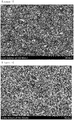
- 238000001000 micrograph Methods 0.000 description 2
- 238000012986 modification Methods 0.000 description 2
- 230000004048 modification Effects 0.000 description 2
- 150000004767 nitrides Chemical class 0.000 description 2
- 229910052757 nitrogen Inorganic materials 0.000 description 2
- 230000006911 nucleation Effects 0.000 description 2
- 238000010899 nucleation Methods 0.000 description 2
- 229910052760 oxygen Inorganic materials 0.000 description 2
- 239000001301 oxygen Substances 0.000 description 2
- 229920000728 polyester Polymers 0.000 description 2
- 239000004810 polytetrafluoroethylene Substances 0.000 description 2
- 229920001343 polytetrafluoroethylene Polymers 0.000 description 2
- 238000007086 side reaction Methods 0.000 description 2
- 238000007581 slurry coating method Methods 0.000 description 2
- 229910052596 spinel Inorganic materials 0.000 description 2
- 239000011029 spinel Substances 0.000 description 2
- VZGDMQKNWNREIO-UHFFFAOYSA-N tetrachloromethane Chemical compound ClC(Cl)(Cl)Cl VZGDMQKNWNREIO-UHFFFAOYSA-N 0.000 description 2
- PYOKUURKVVELLB-UHFFFAOYSA-N trimethyl orthoformate Chemical compound COC(OC)OC PYOKUURKVVELLB-UHFFFAOYSA-N 0.000 description 2
- 238000001771 vacuum deposition Methods 0.000 description 2
- XLYOFNOQVPJJNP-UHFFFAOYSA-N water Substances O XLYOFNOQVPJJNP-UHFFFAOYSA-N 0.000 description 2
- MIZLGWKEZAPEFJ-UHFFFAOYSA-N 1,1,2-trifluoroethene Chemical group FC=C(F)F MIZLGWKEZAPEFJ-UHFFFAOYSA-N 0.000 description 1
- LZDKZFUFMNSQCJ-UHFFFAOYSA-N 1,2-diethoxyethane Chemical compound CCOCCOCC LZDKZFUFMNSQCJ-UHFFFAOYSA-N 0.000 description 1
- CYSGHNMQYZDMIA-UHFFFAOYSA-N 1,3-Dimethyl-2-imidazolidinon Chemical compound CN1CCN(C)C1=O CYSGHNMQYZDMIA-UHFFFAOYSA-N 0.000 description 1
- NVJUHMXYKCUMQA-UHFFFAOYSA-N 1-ethoxypropane Chemical compound CCCOCC NVJUHMXYKCUMQA-UHFFFAOYSA-N 0.000 description 1
- UHOPWFKONJYLCF-UHFFFAOYSA-N 2-(2-sulfanylethyl)isoindole-1,3-dione Chemical compound C1=CC=C2C(=O)N(CCS)C(=O)C2=C1 UHOPWFKONJYLCF-UHFFFAOYSA-N 0.000 description 1
- XNWFRZJHXBZDAG-UHFFFAOYSA-N 2-METHOXYETHANOL Chemical class COCCO XNWFRZJHXBZDAG-UHFFFAOYSA-N 0.000 description 1
- JWUJQDFVADABEY-UHFFFAOYSA-N 2-methyltetrahydrofuran Chemical compound CC1CCCO1 JWUJQDFVADABEY-UHFFFAOYSA-N 0.000 description 1
- PPDFQRAASCRJAH-UHFFFAOYSA-N 2-methylthiolane 1,1-dioxide Chemical compound CC1CCCS1(=O)=O PPDFQRAASCRJAH-UHFFFAOYSA-N 0.000 description 1
- LWLOKSXSAUHTJO-UHFFFAOYSA-N 4,5-dimethyl-1,3-dioxolan-2-one Chemical compound CC1OC(=O)OC1C LWLOKSXSAUHTJO-UHFFFAOYSA-N 0.000 description 1
- BJWMSGRKJIOCNR-UHFFFAOYSA-N 4-ethenyl-1,3-dioxolan-2-one Chemical compound C=CC1COC(=O)O1 BJWMSGRKJIOCNR-UHFFFAOYSA-N 0.000 description 1
- LSUWCXHZPFTZSF-UHFFFAOYSA-N 4-ethyl-5-methyl-1,3-dioxolan-2-one Chemical compound CCC1OC(=O)OC1C LSUWCXHZPFTZSF-UHFFFAOYSA-N 0.000 description 1
- AUXJVUDWWLIGRU-UHFFFAOYSA-N 4-propyl-1,3-dioxolan-2-one Chemical compound CCCC1COC(=O)O1 AUXJVUDWWLIGRU-UHFFFAOYSA-N 0.000 description 1
- 229910000925 Cd alloy Inorganic materials 0.000 description 1
- XDTMQSROBMDMFD-UHFFFAOYSA-N Cyclohexane Chemical compound C1CCCCC1 XDTMQSROBMDMFD-UHFFFAOYSA-N 0.000 description 1
- 229920001780 ECTFE Polymers 0.000 description 1
- PIICEJLVQHRZGT-UHFFFAOYSA-N Ethylenediamine Chemical compound NCCN PIICEJLVQHRZGT-UHFFFAOYSA-N 0.000 description 1
- 229910005143 FSO2 Inorganic materials 0.000 description 1
- PXGOKWXKJXAPGV-UHFFFAOYSA-N Fluorine Chemical compound FF PXGOKWXKJXAPGV-UHFFFAOYSA-N 0.000 description 1
- UFHFLCQGNIYNRP-UHFFFAOYSA-N Hydrogen Chemical compound [H][H] UFHFLCQGNIYNRP-UHFFFAOYSA-N 0.000 description 1
- 229910008722 Li2NiO2 Inorganic materials 0.000 description 1
- 229910007558 Li2SiS3 Inorganic materials 0.000 description 1
- 229910012722 Li3N-LiI-LiOH Inorganic materials 0.000 description 1
- 229910012716 Li3N-LiI—LiOH Inorganic materials 0.000 description 1
- 229910012734 Li3N—LiI—LiOH Inorganic materials 0.000 description 1
- 229910013043 Li3PO4-Li2S-SiS2 Inorganic materials 0.000 description 1
- 229910013035 Li3PO4-Li2S—SiS2 Inorganic materials 0.000 description 1
- 229910012810 Li3PO4—Li2S-SiS2 Inorganic materials 0.000 description 1
- 229910012797 Li3PO4—Li2S—SiS2 Inorganic materials 0.000 description 1
- 229910012047 Li4SiO4-LiI-LiOH Inorganic materials 0.000 description 1
- 229910012075 Li4SiO4-LiI—LiOH Inorganic materials 0.000 description 1
- 229910012057 Li4SiO4—LiI—LiOH Inorganic materials 0.000 description 1
- 229910010739 Li5Ni2 Inorganic materials 0.000 description 1
- 229910012346 LiSiO4-LiI-LiOH Inorganic materials 0.000 description 1
- 229910012345 LiSiO4-LiI—LiOH Inorganic materials 0.000 description 1
- 229910012348 LiSiO4—LiI—LiOH Inorganic materials 0.000 description 1
- KDXKERNSBIXSRK-UHFFFAOYSA-N Lysine Natural products NCCCCC(N)C(O)=O KDXKERNSBIXSRK-UHFFFAOYSA-N 0.000 description 1
- 239000004472 Lysine Substances 0.000 description 1
- XOBKSJJDNFUZPF-UHFFFAOYSA-N Methoxyethane Chemical compound CCOC XOBKSJJDNFUZPF-UHFFFAOYSA-N 0.000 description 1
- RJUFJBKOKNCXHH-UHFFFAOYSA-N Methyl propionate Chemical compound CCC(=O)OC RJUFJBKOKNCXHH-UHFFFAOYSA-N 0.000 description 1
- ZHGDJTMNXSOQDT-UHFFFAOYSA-N NP(N)(N)=O.NP(N)(N)=O.NP(N)(N)=O.NP(N)(N)=O.NP(N)(N)=O.NP(N)(N)=O Chemical compound NP(N)(N)=O.NP(N)(N)=O.NP(N)(N)=O.NP(N)(N)=O.NP(N)(N)=O.NP(N)(N)=O ZHGDJTMNXSOQDT-UHFFFAOYSA-N 0.000 description 1
- 229910019142 PO4 Inorganic materials 0.000 description 1
- 239000004696 Poly ether ether ketone Substances 0.000 description 1
- 229930182556 Polyacetal Natural products 0.000 description 1
- 239000004952 Polyamide Substances 0.000 description 1
- 239000004695 Polyether sulfone Substances 0.000 description 1
- 239000004642 Polyimide Substances 0.000 description 1
- 229920000265 Polyparaphenylene Polymers 0.000 description 1
- 239000004721 Polyphenylene oxide Substances 0.000 description 1
- 239000004734 Polyphenylene sulfide Substances 0.000 description 1
- 239000004372 Polyvinyl alcohol Substances 0.000 description 1
- ZLMJMSJWJFRBEC-UHFFFAOYSA-N Potassium Chemical compound [K] ZLMJMSJWJFRBEC-UHFFFAOYSA-N 0.000 description 1
- NINIDFKCEFEMDL-UHFFFAOYSA-N Sulfur Chemical compound [S] NINIDFKCEFEMDL-UHFFFAOYSA-N 0.000 description 1
- UCKMPCXJQFINFW-UHFFFAOYSA-N Sulphide Chemical compound [S-2] UCKMPCXJQFINFW-UHFFFAOYSA-N 0.000 description 1
- GSEJCLTVZPLZKY-UHFFFAOYSA-N Triethanolamine Chemical compound OCCN(CCO)CCO GSEJCLTVZPLZKY-UHFFFAOYSA-N 0.000 description 1
- 239000004699 Ultra-high molecular weight polyethylene Substances 0.000 description 1
- JDZCKJOXGCMJGS-UHFFFAOYSA-N [Li].[S] Chemical compound [Li].[S] JDZCKJOXGCMJGS-UHFFFAOYSA-N 0.000 description 1
- ZYXUQEDFWHDILZ-UHFFFAOYSA-N [Ni].[Mn].[Li] Chemical compound [Ni].[Mn].[Li] ZYXUQEDFWHDILZ-UHFFFAOYSA-N 0.000 description 1
- 230000000996 additive effect Effects 0.000 description 1
- 239000000853 adhesive Substances 0.000 description 1
- 230000001070 adhesive effect Effects 0.000 description 1
- 238000004220 aggregation Methods 0.000 description 1
- 230000002776 aggregation Effects 0.000 description 1
- 229910052783 alkali metal Inorganic materials 0.000 description 1
- 150000001340 alkali metals Chemical class 0.000 description 1
- 229910001420 alkaline earth metal ion Inorganic materials 0.000 description 1
- 150000001336 alkenes Chemical class 0.000 description 1
- 229910000147 aluminium phosphate Inorganic materials 0.000 description 1
- VSCWAEJMTAWNJL-UHFFFAOYSA-K aluminium trichloride Chemical class Cl[Al](Cl)Cl VSCWAEJMTAWNJL-UHFFFAOYSA-K 0.000 description 1
- 150000001408 amides Chemical class 0.000 description 1
- 150000003863 ammonium salts Chemical class 0.000 description 1
- 229910021383 artificial graphite Inorganic materials 0.000 description 1
- 238000009835 boiling Methods 0.000 description 1
- 239000006229 carbon black Substances 0.000 description 1
- 239000001569 carbon dioxide Substances 0.000 description 1
- 230000015556 catabolic process Effects 0.000 description 1
- 239000003054 catalyst Substances 0.000 description 1
- 230000005779 cell damage Effects 0.000 description 1
- 208000037887 cell injury Diseases 0.000 description 1
- 239000000919 ceramic Substances 0.000 description 1
- 239000006231 channel black Substances 0.000 description 1
- 150000001805 chlorine compounds Chemical class 0.000 description 1
- 239000000470 constituent Substances 0.000 description 1
- 239000011889 copper foil Substances 0.000 description 1
- 239000013078 crystal Substances 0.000 description 1
- 239000002178 crystalline material Substances 0.000 description 1
- 150000004292 cyclic ethers Chemical class 0.000 description 1
- 238000006731 degradation reaction Methods 0.000 description 1
- 238000000151 deposition Methods 0.000 description 1
- 230000008021 deposition Effects 0.000 description 1
- 238000005137 deposition process Methods 0.000 description 1
- 238000004512 die casting Methods 0.000 description 1
- 238000007607 die coating method Methods 0.000 description 1
- XUCJHNOBJLKZNU-UHFFFAOYSA-M dilithium;hydroxide Chemical compound [Li+].[Li+].[OH-] XUCJHNOBJLKZNU-UHFFFAOYSA-M 0.000 description 1
- 150000004862 dioxolanes Chemical class 0.000 description 1
- 238000003618 dip coating Methods 0.000 description 1
- VUPKGFBOKBGHFZ-UHFFFAOYSA-N dipropyl carbonate Chemical compound CCCOC(=O)OCCC VUPKGFBOKBGHFZ-UHFFFAOYSA-N 0.000 description 1
- POLCUAVZOMRGSN-UHFFFAOYSA-N dipropyl ether Chemical compound CCCOCCC POLCUAVZOMRGSN-UHFFFAOYSA-N 0.000 description 1
- 239000006185 dispersion Substances 0.000 description 1
- 238000010494 dissociation reaction Methods 0.000 description 1
- 230000005593 dissociations Effects 0.000 description 1
- 238000009826 distribution Methods 0.000 description 1
- 229940093499 ethyl acetate Drugs 0.000 description 1
- QKBJDEGZZJWPJA-UHFFFAOYSA-N ethyl propyl carbonate Chemical compound [CH2]COC(=O)OCCC QKBJDEGZZJWPJA-UHFFFAOYSA-N 0.000 description 1
- 229920006242 ethylene acrylic acid copolymer Polymers 0.000 description 1
- 229920000840 ethylene tetrafluoroethylene copolymer Polymers 0.000 description 1
- 238000001704 evaporation Methods 0.000 description 1
- 239000012467 final product Substances 0.000 description 1
- 229910052731 fluorine Inorganic materials 0.000 description 1
- 239000011737 fluorine Substances 0.000 description 1
- NBVXSUQYWXRMNV-UHFFFAOYSA-N fluoromethane Chemical compound FC NBVXSUQYWXRMNV-UHFFFAOYSA-N 0.000 description 1
- 239000006232 furnace black Substances 0.000 description 1
- YVIVRJLWYJGJTJ-UHFFFAOYSA-N gamma-Valerolactam Chemical compound CC1CCC(=O)N1 YVIVRJLWYJGJTJ-UHFFFAOYSA-N 0.000 description 1
- 239000007789 gas Substances 0.000 description 1
- 239000003365 glass fiber Substances 0.000 description 1
- 229910002804 graphite Inorganic materials 0.000 description 1
- 239000010439 graphite Substances 0.000 description 1
- 238000007756 gravure coating Methods 0.000 description 1
- 229910052736 halogen Inorganic materials 0.000 description 1
- 150000002367 halogens Chemical class 0.000 description 1
- 229920001903 high density polyethylene Polymers 0.000 description 1
- 239000004700 high-density polyethylene Substances 0.000 description 1
- 238000007602 hot air drying Methods 0.000 description 1
- 229910052739 hydrogen Inorganic materials 0.000 description 1
- 239000001257 hydrogen Substances 0.000 description 1
- 150000002461 imidazolidines Chemical class 0.000 description 1
- 150000003949 imides Chemical class 0.000 description 1
- 230000002401 inhibitory effect Effects 0.000 description 1
- 229910017053 inorganic salt Inorganic materials 0.000 description 1
- 229910052909 inorganic silicate Inorganic materials 0.000 description 1
- 239000011810 insulating material Substances 0.000 description 1
- 239000012212 insulator Substances 0.000 description 1
- 230000010220 ion permeability Effects 0.000 description 1
- 239000003273 ketjen black Substances 0.000 description 1
- 238000010030 laminating Methods 0.000 description 1
- 238000003475 lamination Methods 0.000 description 1
- 239000006233 lamp black Substances 0.000 description 1
- 229920000092 linear low density polyethylene Polymers 0.000 description 1
- 239000004707 linear low-density polyethylene Substances 0.000 description 1
- 229910003473 lithium bis(trifluoromethanesulfonyl)imide Inorganic materials 0.000 description 1
- XGZVUEUWXADBQD-UHFFFAOYSA-L lithium carbonate Chemical compound [Li+].[Li+].[O-]C([O-])=O XGZVUEUWXADBQD-UHFFFAOYSA-L 0.000 description 1
- 229910052808 lithium carbonate Inorganic materials 0.000 description 1
- 150000002642 lithium compounds Chemical class 0.000 description 1
- RSNHXDVSISOZOB-UHFFFAOYSA-N lithium nickel Chemical group [Li].[Ni] RSNHXDVSISOZOB-UHFFFAOYSA-N 0.000 description 1
- 229910001947 lithium oxide Inorganic materials 0.000 description 1
- QSZMZKBZAYQGRS-UHFFFAOYSA-N lithium;bis(trifluoromethylsulfonyl)azanide Chemical compound [Li+].FC(F)(F)S(=O)(=O)[N-]S(=O)(=O)C(F)(F)F QSZMZKBZAYQGRS-UHFFFAOYSA-N 0.000 description 1
- VROAXDSNYPAOBJ-UHFFFAOYSA-N lithium;oxido(oxo)nickel Chemical group [Li+].[O-][Ni]=O VROAXDSNYPAOBJ-UHFFFAOYSA-N 0.000 description 1
- 229920001684 low density polyethylene Polymers 0.000 description 1
- 239000004702 low-density polyethylene Substances 0.000 description 1
- 230000014759 maintenance of location Effects 0.000 description 1
- 229910044991 metal oxide Inorganic materials 0.000 description 1
- 150000004706 metal oxides Chemical class 0.000 description 1
- VNKYTQGIUYNRMY-UHFFFAOYSA-N methoxypropane Chemical compound CCCOC VNKYTQGIUYNRMY-UHFFFAOYSA-N 0.000 description 1
- KKQAVHGECIBFRQ-UHFFFAOYSA-N methyl propyl carbonate Chemical compound CCCOC(=O)OC KKQAVHGECIBFRQ-UHFFFAOYSA-N 0.000 description 1
- 238000000465 moulding Methods 0.000 description 1
- YKYONYBAUNKHLG-UHFFFAOYSA-N n-Propyl acetate Natural products CCCOC(C)=O YKYONYBAUNKHLG-UHFFFAOYSA-N 0.000 description 1
- 229910021382 natural graphite Inorganic materials 0.000 description 1
- 239000007773 negative electrode material Substances 0.000 description 1
- 150000005181 nitrobenzenes Chemical class 0.000 description 1
- 239000012299 nitrogen atmosphere Substances 0.000 description 1
- LYGJENNIWJXYER-UHFFFAOYSA-N nitromethane Chemical compound C[N+]([O-])=O LYGJENNIWJXYER-UHFFFAOYSA-N 0.000 description 1
- 239000011356 non-aqueous organic solvent Substances 0.000 description 1
- JRZJOMJEPLMPRA-UHFFFAOYSA-N olefin Natural products CCCCCCCC=C JRZJOMJEPLMPRA-UHFFFAOYSA-N 0.000 description 1
- 239000010450 olivine Substances 0.000 description 1
- 229910052609 olivine Inorganic materials 0.000 description 1
- 150000002894 organic compounds Chemical class 0.000 description 1
- 230000003647 oxidation Effects 0.000 description 1
- 238000007254 oxidation reaction Methods 0.000 description 1
- 230000033116 oxidation-reduction process Effects 0.000 description 1
- 235000021317 phosphate Nutrition 0.000 description 1
- NBIIXXVUZAFLBC-UHFFFAOYSA-N phosphoric acid Substances OP(O)(O)=O NBIIXXVUZAFLBC-UHFFFAOYSA-N 0.000 description 1
- 150000003013 phosphoric acid derivatives Chemical class 0.000 description 1
- 150000003014 phosphoric acid esters Chemical class 0.000 description 1
- 238000007747 plating Methods 0.000 description 1
- 229920002493 poly(chlorotrifluoroethylene) Polymers 0.000 description 1
- 229920003207 poly(ethylene-2,6-naphthalate) Polymers 0.000 description 1
- 229920002647 polyamide Polymers 0.000 description 1
- 229920001748 polybutylene Polymers 0.000 description 1
- 229920001707 polybutylene terephthalate Polymers 0.000 description 1
- 239000004417 polycarbonate Substances 0.000 description 1
- 229920000515 polycarbonate Polymers 0.000 description 1
- 239000005023 polychlorotrifluoroethylene (PCTFE) polymer Substances 0.000 description 1
- 229920006393 polyether sulfone Polymers 0.000 description 1
- 229920002530 polyetherether ketone Polymers 0.000 description 1
- 239000011112 polyethylene naphthalate Substances 0.000 description 1
- 229920000139 polyethylene terephthalate Polymers 0.000 description 1
- 239000005020 polyethylene terephthalate Substances 0.000 description 1
- 229920001721 polyimide Polymers 0.000 description 1
- 229920006324 polyoxymethylene Polymers 0.000 description 1
- 229920006380 polyphenylene oxide Polymers 0.000 description 1
- 229920000069 polyphenylene sulfide Polymers 0.000 description 1
- 229920001451 polypropylene glycol Polymers 0.000 description 1
- 229920002451 polyvinyl alcohol Polymers 0.000 description 1
- 229910052700 potassium Inorganic materials 0.000 description 1
- 239000011591 potassium Substances 0.000 description 1
- 239000000843 powder Substances 0.000 description 1
- 238000003825 pressing Methods 0.000 description 1
- 229940090181 propyl acetate Drugs 0.000 description 1
- UMJSCPRVCHMLSP-UHFFFAOYSA-N pyridine Natural products COC1=CC=CN=C1 UMJSCPRVCHMLSP-UHFFFAOYSA-N 0.000 description 1
- 239000002096 quantum dot Substances 0.000 description 1
- 239000001008 quinone-imine dye Substances 0.000 description 1
- 230000002829 reductive effect Effects 0.000 description 1
- 229920005989 resin Polymers 0.000 description 1
- 239000011347 resin Substances 0.000 description 1
- 238000007763 reverse roll coating Methods 0.000 description 1
- 150000003839 salts Chemical class 0.000 description 1
- 238000007650 screen-printing Methods 0.000 description 1
- 150000003346 selenoethers Chemical class 0.000 description 1
- 238000004528 spin coating Methods 0.000 description 1
- 229920003048 styrene butadiene rubber Polymers 0.000 description 1
- HXJUTPCZVOIRIF-UHFFFAOYSA-N sulfolane Chemical compound O=S1(=O)CCCC1 HXJUTPCZVOIRIF-UHFFFAOYSA-N 0.000 description 1
- 229910052717 sulfur Inorganic materials 0.000 description 1
- 239000011593 sulfur Substances 0.000 description 1
- 150000003467 sulfuric acid derivatives Chemical class 0.000 description 1
- 230000001629 suppression Effects 0.000 description 1
- 239000002345 surface coating layer Substances 0.000 description 1
- 230000008961 swelling Effects 0.000 description 1
- YLQBMQCUIZJEEH-UHFFFAOYSA-N tetrahydrofuran Natural products C=1C=COC=1 YLQBMQCUIZJEEH-UHFFFAOYSA-N 0.000 description 1
- 239000006234 thermal black Substances 0.000 description 1
- 229920005992 thermoplastic resin Polymers 0.000 description 1
- 229920001187 thermosetting polymer Polymers 0.000 description 1
- 150000003568 thioethers Chemical class 0.000 description 1
- OGIDPMRJRNCKJF-UHFFFAOYSA-N titanium oxide Inorganic materials [Ti]=O OGIDPMRJRNCKJF-UHFFFAOYSA-N 0.000 description 1
- 238000012546 transfer Methods 0.000 description 1
- 229910000314 transition metal oxide Inorganic materials 0.000 description 1
- BDZBKCUKTQZUTL-UHFFFAOYSA-N triethyl phosphite Chemical compound CCOP(OCC)OCC BDZBKCUKTQZUTL-UHFFFAOYSA-N 0.000 description 1
- 125000001814 trioxo-lambda(7)-chloranyloxy group Chemical group *OCl(=O)(=O)=O 0.000 description 1
- 229920000785 ultra high molecular weight polyethylene Polymers 0.000 description 1
- DNYWZCXLKNTFFI-UHFFFAOYSA-N uranium Chemical compound [U][U][U][U][U][U][U][U][U][U][U][U][U][U][U][U][U][U][U][U][U][U][U][U][U][U][U][U][U][U][U][U][U][U][U][U][U][U][U][U][U][U][U][U][U][U][U][U][U][U][U][U][U][U][U][U][U][U][U][U][U][U][U][U][U][U][U][U][U][U][U][U][U][U][U][U][U][U][U][U][U][U][U][U][U][U][U][U][U][U][U][U][U][U][U][U][U][U][U][U][U][U][U][U][U][U][U][U][U][U][U][U][U][U] DNYWZCXLKNTFFI-UHFFFAOYSA-N 0.000 description 1
- NQPDZGIKBAWPEJ-UHFFFAOYSA-N valeric acid Chemical compound CCCCC(O)=O NQPDZGIKBAWPEJ-UHFFFAOYSA-N 0.000 description 1
- GPPXJZIENCGNKB-UHFFFAOYSA-N vanadium Chemical compound [V]#[V] GPPXJZIENCGNKB-UHFFFAOYSA-N 0.000 description 1
- 239000011787 zinc oxide Substances 0.000 description 1
- PAPBSGBWRJIAAV-UHFFFAOYSA-N ε-Caprolactone Chemical compound O=C1CCCCCO1 PAPBSGBWRJIAAV-UHFFFAOYSA-N 0.000 description 1
Images


Classifications
-
- H—ELECTRICITY
- H01—ELECTRIC ELEMENTS
- H01M—PROCESSES OR MEANS, e.g. BATTERIES, FOR THE DIRECT CONVERSION OF CHEMICAL ENERGY INTO ELECTRICAL ENERGY
- H01M4/00—Electrodes
- H01M4/02—Electrodes composed of, or comprising, active material
- H01M4/13—Electrodes for accumulators with non-aqueous electrolyte, e.g. for lithium-accumulators; Processes of manufacture thereof
- H01M4/134—Electrodes based on metals, Si or alloys
-
- H—ELECTRICITY
- H01—ELECTRIC ELEMENTS
- H01M—PROCESSES OR MEANS, e.g. BATTERIES, FOR THE DIRECT CONVERSION OF CHEMICAL ENERGY INTO ELECTRICAL ENERGY
- H01M4/00—Electrodes
- H01M4/02—Electrodes composed of, or comprising, active material
- H01M4/13—Electrodes for accumulators with non-aqueous electrolyte, e.g. for lithium-accumulators; Processes of manufacture thereof
-
- H—ELECTRICITY
- H01—ELECTRIC ELEMENTS
- H01M—PROCESSES OR MEANS, e.g. BATTERIES, FOR THE DIRECT CONVERSION OF CHEMICAL ENERGY INTO ELECTRICAL ENERGY
- H01M10/00—Secondary cells; Manufacture thereof
- H01M10/05—Accumulators with non-aqueous electrolyte
- H01M10/052—Li-accumulators
-
- H—ELECTRICITY
- H01—ELECTRIC ELEMENTS
- H01M—PROCESSES OR MEANS, e.g. BATTERIES, FOR THE DIRECT CONVERSION OF CHEMICAL ENERGY INTO ELECTRICAL ENERGY
- H01M4/00—Electrodes
- H01M4/02—Electrodes composed of, or comprising, active material
- H01M4/04—Processes of manufacture in general
- H01M4/0438—Processes of manufacture in general by electrochemical processing
- H01M4/044—Activating, forming or electrochemical attack of the supporting material
- H01M4/0445—Forming after manufacture of the electrode, e.g. first charge, cycling
- H01M4/0447—Forming after manufacture of the electrode, e.g. first charge, cycling of complete cells or cells stacks
-
- H—ELECTRICITY
- H01—ELECTRIC ELEMENTS
- H01M—PROCESSES OR MEANS, e.g. BATTERIES, FOR THE DIRECT CONVERSION OF CHEMICAL ENERGY INTO ELECTRICAL ENERGY
- H01M4/00—Electrodes
- H01M4/02—Electrodes composed of, or comprising, active material
- H01M4/36—Selection of substances as active materials, active masses, active liquids
- H01M4/362—Composites
- H01M4/366—Composites as layered products
-
- H—ELECTRICITY
- H01—ELECTRIC ELEMENTS
- H01M—PROCESSES OR MEANS, e.g. BATTERIES, FOR THE DIRECT CONVERSION OF CHEMICAL ENERGY INTO ELECTRICAL ENERGY
- H01M4/00—Electrodes
- H01M4/02—Electrodes composed of, or comprising, active material
- H01M4/36—Selection of substances as active materials, active masses, active liquids
- H01M4/38—Selection of substances as active materials, active masses, active liquids of elements or alloys
- H01M4/381—Alkaline or alkaline earth metals elements
- H01M4/382—Lithium
-
- H—ELECTRICITY
- H01—ELECTRIC ELEMENTS
- H01M—PROCESSES OR MEANS, e.g. BATTERIES, FOR THE DIRECT CONVERSION OF CHEMICAL ENERGY INTO ELECTRICAL ENERGY
- H01M4/00—Electrodes
- H01M4/02—Electrodes composed of, or comprising, active material
- H01M4/36—Selection of substances as active materials, active masses, active liquids
- H01M4/48—Selection of substances as active materials, active masses, active liquids of inorganic oxides or hydroxides
- H01M4/485—Selection of substances as active materials, active masses, active liquids of inorganic oxides or hydroxides of mixed oxides or hydroxides for inserting or intercalating light metals, e.g. LiTi2O4 or LiTi2OxFy
-
- H—ELECTRICITY
- H01—ELECTRIC ELEMENTS
- H01M—PROCESSES OR MEANS, e.g. BATTERIES, FOR THE DIRECT CONVERSION OF CHEMICAL ENERGY INTO ELECTRICAL ENERGY
- H01M4/00—Electrodes
- H01M4/02—Electrodes composed of, or comprising, active material
- H01M4/36—Selection of substances as active materials, active masses, active liquids
- H01M4/48—Selection of substances as active materials, active masses, active liquids of inorganic oxides or hydroxides
- H01M4/50—Selection of substances as active materials, active masses, active liquids of inorganic oxides or hydroxides of manganese
- H01M4/505—Selection of substances as active materials, active masses, active liquids of inorganic oxides or hydroxides of manganese of mixed oxides or hydroxides containing manganese for inserting or intercalating light metals, e.g. LiMn2O4 or LiMn2OxFy
-
- H—ELECTRICITY
- H01—ELECTRIC ELEMENTS
- H01M—PROCESSES OR MEANS, e.g. BATTERIES, FOR THE DIRECT CONVERSION OF CHEMICAL ENERGY INTO ELECTRICAL ENERGY
- H01M4/00—Electrodes
- H01M4/02—Electrodes composed of, or comprising, active material
- H01M4/36—Selection of substances as active materials, active masses, active liquids
- H01M4/48—Selection of substances as active materials, active masses, active liquids of inorganic oxides or hydroxides
- H01M4/52—Selection of substances as active materials, active masses, active liquids of inorganic oxides or hydroxides of nickel, cobalt or iron
- H01M4/525—Selection of substances as active materials, active masses, active liquids of inorganic oxides or hydroxides of nickel, cobalt or iron of mixed oxides or hydroxides containing iron, cobalt or nickel for inserting or intercalating light metals, e.g. LiNiO2, LiCoO2 or LiCoOxFy
-
- H—ELECTRICITY
- H01—ELECTRIC ELEMENTS
- H01M—PROCESSES OR MEANS, e.g. BATTERIES, FOR THE DIRECT CONVERSION OF CHEMICAL ENERGY INTO ELECTRICAL ENERGY
- H01M4/00—Electrodes
- H01M4/02—Electrodes composed of, or comprising, active material
- H01M4/62—Selection of inactive substances as ingredients for active masses, e.g. binders, fillers
- H01M4/628—Inhibitors, e.g. gassing inhibitors, corrosion inhibitors
-
- H—ELECTRICITY
- H01—ELECTRIC ELEMENTS
- H01M—PROCESSES OR MEANS, e.g. BATTERIES, FOR THE DIRECT CONVERSION OF CHEMICAL ENERGY INTO ELECTRICAL ENERGY
- H01M4/00—Electrodes
- H01M4/02—Electrodes composed of, or comprising, active material
- H01M4/64—Carriers or collectors
- H01M4/66—Selection of materials
- H01M4/661—Metal or alloys, e.g. alloy coatings
-
- H—ELECTRICITY
- H01—ELECTRIC ELEMENTS
- H01M—PROCESSES OR MEANS, e.g. BATTERIES, FOR THE DIRECT CONVERSION OF CHEMICAL ENERGY INTO ELECTRICAL ENERGY
- H01M4/00—Electrodes
- H01M4/02—Electrodes composed of, or comprising, active material
- H01M4/64—Carriers or collectors
- H01M4/66—Selection of materials
- H01M4/665—Composites
- H01M4/667—Composites in the form of layers, e.g. coatings
-
- Y—GENERAL TAGGING OF NEW TECHNOLOGICAL DEVELOPMENTS; GENERAL TAGGING OF CROSS-SECTIONAL TECHNOLOGIES SPANNING OVER SEVERAL SECTIONS OF THE IPC; TECHNICAL SUBJECTS COVERED BY FORMER USPC CROSS-REFERENCE ART COLLECTIONS [XRACs] AND DIGESTS
- Y02—TECHNOLOGIES OR APPLICATIONS FOR MITIGATION OR ADAPTATION AGAINST CLIMATE CHANGE
- Y02E—REDUCTION OF GREENHOUSE GAS [GHG] EMISSIONS, RELATED TO ENERGY GENERATION, TRANSMISSION OR DISTRIBUTION
- Y02E60/00—Enabling technologies; Technologies with a potential or indirect contribution to GHG emissions mitigation
- Y02E60/10—Energy storage using batteries
Definitions
- the present invention relates to a lithium secondary battery having a negative electrode free (anode free) structure using metal particles.
- Lithium metal has a property of low oxidation-reduction potential (-3.045 V with respect to standard hydrogen electrode) and large weight energy density (3,860 mAhg -1 ), and has been expected as a negative electrode material of high capacity secondary batteries.
- the battery when using lithium metal as a battery negative electrode, the battery is generally manufactured by attaching lithium foil on a flat current collector, and since lithium explosively reacts with water and also reacts with oxygen in the atmosphere with its high reactivity as an alkali metal, there is a disadvantage in that manufacture and use are difficult under general environments.
- an oxide layer such as LiOH, Li 2 O and Li 2 CO 3 is obtained as a result of oxidation when lithium metal is exposed to the atmosphere.
- a surface oxide layer (native layer) is present on the surface, the oxide layer functions as an insulator film decreasing electrical conductivity, and causes a problem of increasing electric resistance by inhibiting smooth lithium ion migration.
- the inventors of the present invention have designed a negative electrode free (anode free) battery structure capable of forming a lithium metal layer on a negative electrode current collector by lithium ions transferred from a positive electrode active material through charge after assembling the battery so as to fundamentally block a contact of the lithium metal with the atmosphere when assembling the battery, and have developed a composition of a positive electrode active material capable of stably forming the lithium metal layer.
- an aspect of the present invention provides a lithium secondary battery having enhanced performance and lifetime by resolving a problem caused by lithium metal reactivity and a problem occurring during an assembly process.
- a lithium secondary battery including a positive electrode, a negative electrode including a negative electrode current collector, and a separator and an electrolyte interposed between the positive and negative electrodes, wherein:
- the lithium metal formed on the negative electrode current collector is formed through one-time charge with a voltage of 4.5 V to 2.5 V.
- a lithium secondary battery according to the present invention is coated while being blocked from the atmosphere through a process of forming a lithium metal layer on a negative electrode current collector, and therefore, may suppress formation of a surface oxide layer in the lithium metal caused by oxygen and moisture in the atmosphere, and as a result, an effect of enhancing cycle lifetime properties is obtained.
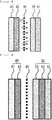
- FIG. 1 is a sectional diagram of a lithium secondary battery manufactured according to a first embodiment of the present disclosure not falling under the scope of the invention as claimed in the appended claims, which is provided with a positive electrode (10) including a positive electrode current collector (11) and a positive electrode mixture (12); a negative electrode (20) including a negative electrode current collector (21); and a separator (30) and an electrolyte (not shown) interposed therebetween.
- a positive electrode including a positive electrode current collector (11) and a positive electrode mixture (12)
- separator (30) and an electrolyte (not shown) interposed therebetween is provided with a positive electrode (10) including a positive electrode current collector (11) and a positive electrode mixture (12); a negative electrode (20) including a negative electrode current collector (21); and a separator (30) and an electrolyte (not shown) interposed therebetween.
- the negative electrode As for a negative electrode of a lithium secondary battery, the negative electrode is normally formed on a negative electrode current collector (21), however, in the present invention, a negative electrode free battery structure is assembled using only with a negative electrode current collector (21) having metal particles (27) formed on the surface, and then, through charge, lithium ions released from a positive electrode mixture (13) form a lithium metal layer (not shown) on the negative electrode current collector(21) as a negative electrode mixture to form a negative electrode having a known constitution of negative electrode current collector/negative electrode mixture, and as a result, a constitution of a common lithium secondary battery is formed.
- a negative electrode free battery in the present invention may be a battery that is negative electrode free in which a negative electrode is not formed on a negative electrode current collector in initial assembly, or may be a concept including all batteries that may have a negative electrode by forming a negative electrode on a negative electrode current collector according to use.
- the form of lithium metal formed on a negative electrode current collector as a negative electrode mixture includes both a form in which lithium metal is formed into a layer, and a structure in which lithium metal is not formed into a layer (for example, a structure in which lithium metal aggregates in a particle form).
- the present invention is described based on a form of a lithium metal layer (23) in which lithium metal is formed into a layer, however, it is obvious that such a description does not exclude a structure in which lithium metal is not formed into a layer.
- FIG. 2 is a mimetic diagram showing lithium ion (Li + ) migration when initially charging a lithium secondary battery manufactured according to a first embodiment of the present invention
- FIG. 3 is a mimetic diagram after completing initial charge of a lithium secondary battery manufactured according to a first embodiment of the present invention.
- lithium ions are released from a positive electrode mixture (13) in a positive electrode (10) when charging a lithium secondary battery having a negative electrode free battery structure by applying a voltage of certain level or higher, and these ions migrate toward a negative electrode current collector (21) side after passing through a separator (30), and a lithium metal layer (23) formed purely with lithium is formed on the negative electrode current collector (21) to form a negative electrode (20).
- metal particles (27) formed with metals or metalloids capable of forming an alloy with lithium the lithium metal layer (23) may be more readily formed, and a denser thin film structure may be formed.
- Such lithium metal layer (23) formation through charge has advantages of forming a thin film layer and very readily controlling interface properties compared to an existing negative electrode sputtering a lithium metal layer (23) on a negative electrode current collector (21) or laminating lithium foil and a negative electrode current collector (21).
- binding strength of the lithium metal layer (23) laminated on the negative electrode current collector (21) is high and stable, a problem of being removed from the negative electrode current collector (21) by going back to an ionization state through discharge does not occur.
- the lithium metal is not exposed to the atmosphere at all during a battery assembly process, and therefore, existing problems such as forming a surface oxide layer due to high reactivity of lithium itself, and a decrease in the lifetime of a lithium secondary battery caused therefrom may be fundamentally blocked.
- the negative electrode current collector (21) forming the negative electrode has a thickness of 3 ⁇ m to 500 ⁇ m, and having metal particles (27) formed on the surface is used.
- metal particles (27) Li nucleation over potential may occur depending on the material of the negative electrode current collector, and due to such resistance, a decrease in the initial Coulombic efficiency may occur. Therefore, when forming metal particles (27), Li nucleation over potential may hardly exist when Li ions are precipitated as Li by charge transfer depending on the material of the metal particles (27).
- the metal particles (27) are metals or metalloids capable of forming an alloy with lithium, and may include at least one selected from the group consisting of aluminum, gold, bismuth, germanium, magnesium, manganese, molybdenum, sodium, nickel, osmium, lead, palladium, platinum, plutonium, rubidium, rhodium, ruthenium, antimony, silicon, tin, strontium, tantalum, tellurium, titanium, uranium, vanadium, tungsten, zinc and zirconium. Silver or gold is preferably used.
- the metal particles (27) are included in a content of 0.1% by weight to 40% by weight and preferably in a content of 1% by weight to 20% by weight with respect to the current collector.
- the metal particle (27) content is less than 0.1% by weight, the particles are not uniformly formed decreasing plating efficiency of the Li metal, and when the content is greater than 40% by weight, the current collector weight increases, and electric energy density may be lowered or the metal may be formed into a layer instead of particles.
- the metal particle (27) formation is not particularly limited in the present invention, and known methods may be used.
- a dry method such as a chemical vapor deposition (CVD) method, a sputtering method, an e-beam evaporation method, an atomic layer deposition (ALD) method or a vacuum deposition method may be used.
- a precursor including a metal of the metal particles (27) may be coated and then heat treated to form the metal particles.
- known precursors such as chlorides or nitrides may be used. Through the heat treatment, dewetting occurs due to changes in the material surface energy and an aggregation phenomenon, a unique property of the material, and the coating layer is changed into a nano dot form as a result.
- a catalyst material coating layer generally changes to a metal particle form when heat treated for 10 minutes at a temperature of approximately 250°C.
- Such metal particles (27) perform a role of a seed for growing lithium ions transferred from a positive electrode to a lithium metal layer (23).
- the formed lithium metal layer (23) has a dense while uniform microstructure on the negative electrode current collector (21) .
- the metal particles (27) are present in an island form rather than a continuous layer of the coating layer on the negative electrode current collector (21) in order to perform a role as a seed.
- the metal particles (27) are formed on the negative electrode current collector (21) while being separated with a gap of greater than or equal to 1 nm and less than 10 ⁇ m and preferably with a gap of greater than or equal to 1 nm and less than 2 ⁇ m.
- the negative electrode current collector (21) capable of forming a lithium metal layer (23) through charge is not particularly limited as long as it has conductivity without inducing chemical changes to a lithium secondary battery.
- copper, stainless steel, aluminum, nickel, titanium, baked carbon, copper or stainless steel of which surface is treated with carbon, nickel, titanium, silver and the like, aluminum-cadmium alloys and the like may be used.
- the negative electrode current collector (21) various forms such as films, sheets, foil, nets, porous bodies, foams and non-woven fabrics having micro-unevenness formed on the surface may be used as the negative electrode current collector (21).
- the lithium secondary battery having a negative electrode free structure provided with such a metal particle (27)-formed negative electrode current collector (21) may be obtained using various methods, however, a method of controlling a composition used in a positive electrode mixture (13) is used in the present invention.
- the positive electrode mixture (13) various positive electrode active materials may be used depending on the battery type, and although the positive electrode active material used in the present invention is not particularly limited as long as it is capable of intercalating or deintercalating lithium ions, a lithium transition metal oxide is typically used currently as a lithium transition metal compound included in a positive electrode active material capable of obtaining a battery with excellent lifetime properties and charge and discharge efficiency.
- the lithium transition metal oxide includes 2 or more transition metals, and examples thereof may include layer compounds such as lithium cobalt oxide (LiCoO 2 ) or lithium nickel oxide (LiNiO 2 ) substituted with one or more transition metals; lithium manganese oxides substituted with one or more transition metals, lithium nickel-based oxides, spinel-based lithium nickel manganese composite oxides, spinel-based lithium manganese oxides in which some of Li in the chemical formula are substituted with alkaline-earth metal ions, olivine-based lithium metal phosphates and the like, but are not limited thereto.
- layer compounds such as lithium cobalt oxide (LiCoO 2 ) or lithium nickel oxide (LiNiO 2 ) substituted with one or more transition metals
- lithium manganese oxides substituted with one or more transition metals lithium nickel-based oxides, spinel-based lithium nickel manganese composite oxides, spinel-based lithium manganese oxides in which some of Li in the chemical formula are substituted with alkaline-
- the lithium transition metal oxide is used in the positive electrode mixture (13) as a positive electrode active material together with a binder, a conductor and the like.
- a lithium source for forming the lithium metal layer (23) becomes the lithium transition metal oxide.
- lithium ions in the lithium transition metal oxide is released when charging in a specific voltage range, and form a lithium metal layer (23) on the negative electrode current collector (21).
- a lithium metal compound a highly irreversible material, having initial charge capacity of 200 mAh/g or greater when one-time charging with 0.01 C to 0.2 C in a voltage range of 4.5 V to 2.5 V, or having initial irreversibility of 30% or greater as an additive capable of providing a lithium source to the lithium transition metal oxide.
- the 'highly irreversible material' mentioned in the present invention may be used to have the same meaning as a 'large capacity irreversible material' in another term, and this means a material having large irreversible capacity of a first cycle of charge and discharge, that is, "(first cycle charge capacity-first cycle discharge capacity)/first cycle charge capacity".
- a highly irreversible material may irreversibly provide lithium ions in excess during a first cycle of charge and discharge.
- it may be, among lithium transition metal compounds capable of intercalating or deintercalating lithium ions, a positive electrode material having high irreversible capacity (first cycle charge capacity-first cycle discharge capacity) of a first cycle of charge and discharge.
- Irreversible capacity of a generally used positive electrode active material is approximately from 2% to 10% with respect to initial capacity, however, in the present invention, a lithium metal compound that is a highly irreversible material, that is, a lithium metal compound having initial irreversibility of 30% or greater and preferably 50% or greater with respect to initial charge capacity may be used together.
- a lithium metal compound those having initial charge capacity of 200 mAh/g or greater and preferably 230 mAh/g or greater may be used. With such lithium metal compound use, a role of a lithium source capable of forming a lithium metal layer (23) may be performed while increasing irreversible capacity of the lithium transition metal oxide that is a positive electrode active material.
- the lithium metal compounds of Chemical Formula 1 to Chemical Formula 8 have different irreversible capacity depending on the structure. These may be used either alone or as a mixture thereof, and perform a role of increasing irreversible capacity of a positive electrode active material.
- the highly irreversible materials represented by Chemical Formulae 1 and 3 have different irreversible capacity depending on the type, and as one example, have numerical values as shown in the following Table 1.
- Table 1 Initial Charge Capacity (mAh/g) Initial Discharge Capacity (mAh/g) Initial Coulombic Efficiency Initial Irreversible Capacity Ratio
- the lithium metal compound of Chemical Formula 2 preferably belongs to space group Immm, and among these, Ni and M composite oxide forming a plane quadrature (Ni, M)O4 and the plane quadrature forming a primary chain while sharing an opposite side (side formed by O-O) is more preferred.
- the lithium metal compound of Chemical Formula 8 has an alkaline-earth metal content of 30 atom% to 45 atom%, and a nitrogen content of 30 atom% to 45 atom%.
- the alkaline-earth metal content and the nitrogen content are in the above-mentioned range, thermal properties and lithium ion conducting properties of the compound of Chemical Formula 1 are excellent.
- k/(k+m+n) is from 0.15 to 0.35 and for example, is from 0.2 to 0.33
- m/(k+m+n) is from 0.30 to 0.45, and for example, is from 0.31 to 0.33
- n/(k+m+n) is from 0.30 to 0.45, and for example, is from 0.31 to 0.33.
- a is from 0.5 to 1
- b is 1
- c is 1 in the electrode active material of Chemical Formula 1.
- the active material When forming a coating layer with the compound of any one of Chemical Formulae 1 to 8, the active material exhibits stable properties while retaining low resistance properties even under an environment of lithium ions being consistently intercalated and deintercalated.
- the coating layer has a thickness of 1 nm to 100 nm. When the coating layer thickness is in the above-mentioned range, the positive electrode active material has excellent ion conducting properties.
- an average particle diameter of the positive electrode active material is from 1 ⁇ m to 30 ⁇ m, and according to one embodiment, is from 8 ⁇ m to 12 ⁇ m.
- the positive electrode active material has an average particle diameter in the above-mentioned range, excellent battery capacity properties are obtained.
- Examples of the alkaline-earth metal-doped core active material may include magnesium-doped LiCoO 2 .
- the magnesium content is from 0.01 parts by weight to 3 parts by weight based on 100 parts by weight of the core active material.
- the lithium transition metal oxide is used in the positive electrode mixture (13) as a positive electrode active material together with a binder, a conductor and the like.
- a lithium source for forming the lithium metal layer (23) becomes the lithium transition metal oxide.
- lithium ions in the lithium transition metal oxide is detached when charging in a specific voltage range, and form a lithium metal layer (23) on the negative electrode current collector (21).
- the charging range for forming the lithium metal layer (23) in the present invention one-time charge is performed with 0.01 to 0.2C in a voltage range of 4.5 V to 2.5 V.
- the charge is performed below the above-mentioned range, the lithium metal layer (23) is difficult to form, and when the charge is performed above the above-mentioned range, cell damage is caused, and charge and discharge are not properly progressed after overdischarge occurs.
- the formed lithium metal layer (23) forms a uniform continuous or discontinuous layer on the negative electrode current collector (21).
- the negative electrode current collector (21) has a foil form
- a continuous thin film form may be obtained
- the negative electrode current collector (21) has a three-dimensional porous structure
- the lithium metal layer (23) may be discontinuously formed.
- the discontinuous layer has a discontinuously distributed form, and, by a region in which the lithium metal layer (23) is present and a region in which the lithium metal layer (23) is not present being present in a specific region and the region in which the lithium metal layer (23) is not present being distributed so as to isolate, disconnect or separate the region in which the lithium compound is present like an island type, means the region in which the lithium metal layer (23) is present being distributed without continuity.
- the lithium metal layer (23) formed through such charge and discharge has a thickness of a minimum of 50 nm or greater, 100 ⁇ m or less, and preferably 1 ⁇ m to 50 ⁇ m in order to function as a negative electrode.
- the thickness is less than the above-mentioned range, battery charge and discharge efficiency rapidly decreases, and, on the contrary, the thickness being greater than the above-mentioned range has a problem of reducing energy density of a battery although lifetime properties and the like are stable.
- the lithium metal layer (23) provided in the present invention being prepared into a negative electrode free battery without lithium metal when assembling a battery, no or almost no oxide layer is formed on the lithium metal layer (23) due to high reactivity of lithium produced during an assembly process compared to a lithium secondary battery assembled using existing lithium foil. As a result, degradation in the battery lifetime caused by the oxide layer may be prevented.
- the lithium metal layer (23) moves by charge of a highly irreversible material, and compared to forming a lithium metal layer (23) on a positive electrode, a more stable lithium metal layer (23) may be formed.
- a chemical reaction may occur between the positive electrode and the lithium metal.
- a positive electrode mixture (13) is formed including the positive electrode active material and the lithium metal compound, and herein, the positive electrode mixture (13) may further include a conductor, a binder, and other additives commonly used in a lithium secondary battery.
- the conductor is used for further enhancing conductivity of the electrode active material.
- a conductor is not particularly limited as long as it has conductivity without inducing chemical changes to the corresponding battery, and examples thereof may include graphite such as natural graphite or artificial graphite; carbon black such as carbon black, acetylene black, ketjen black, channel black, furnace black, lamp black or thermal black; conductive fibers such as carbon fiber or metal fiber; fluorocarbon, aluminum, metal powders such as nickel powder; conductive whiskers such as zinc oxide or potassium titania; conductive metal oxides such as titanium oxide; polyphenylene derivatives and the like.
- a binder may be further included for binding the positive electrode active material, the lithium metal compound and the conductor, and for binding on the current collector.
- the binder may include a thermoplastic resin or a thermosetting resin.
- a thermoplastic resin for example, polyethylene, polypropylene, polytetrafluoroethylene (PTFE), polyvinylidene fluoride (PVDF), styrene-butadiene rubber, a tetrafluoroethylene-perfluoro alkylvinyl ether copolymer, a vinylidene fluoride-hexafluoropropylene copolymer, a vinylidene fluoride-chlorotrifluoroethylene copolymer, an ethylene-tetrafluoroethylene copolymer, a polychlorotrifluoroethylene, vinylidene fluoride-pentafluoropropylene copolymer, a propylene-tetrafluoroethylene copolymer, an ethylene
- Examples of other additives may include a filler.
- the filler is selectively used as a component suppressing electrode expansion, and is not particularly limited as long as it is a fibrous material without inducing chemical changes to the corresponding battery.
- olefin-based polymers such as polyethylene or polypropylene, or fibrous materials such as glass fiber or carbon fiber may be used.
- the positive electrode mixture (13) of the present invention is formed on a positive electrode current collector (11).
- the positive electrode current collector is generally prepared to a thickness of 3 ⁇ m to 500 ⁇ m.
- a positive electrode current collector (11) is not particularly limited as long as it has high conductivity without inducing chemical changes to a lithium secondary battery, and for example, stainless steel, aluminum, nickel, titanium, baked carbon, or aluminum or stainless carbon of which surface is treated with carbon, nickel, titanium, silver and the like may be used.
- the positive electrode current collector (11) may be used in various forms such as films, sheets, foil, nets, porous bodies, foams and non-woven fabrics having micro-unevenness formed on the surface so as to increase adhesive strength with a positive electrode active material.
- a method of coating the positive electrode mixture (13) on the current collector may include a method of distributing the electrode mixture slurry on the current collector and then uniformly dispersing the result using a doctor blade or the like, a method such as die casting, comma coating or screen printing, and the like.
- the electrode mixture slurry may be bonded with the current collector using a pressing or lamination method after molding on a separate substrate, however, the method is not limited thereto.
- the lithium secondary battery according to a second embodiment of the present disclosure further forms a protective film (55) on a surface in contact with the separator (60) in the negative electrode.
- a lithium metal layer (23) is formed by, as shown in FIG. 4 , lithium ions transferred from a positive electrode mixture (43) passing through a protective film (55) and being formed on a negative electrode current collector (51), and grows from metal particles (57).
- lithium ion conducting polymers and/or inorganic solid electrolytes are used, and as necessary, a lithium salt may be further included.
- lithium ion conducting polymer may include any one selected from the group consisting of polyethylene oxide (PEO), polyacrylonitrile (PAN), polymethyl methacrylate (PMMA), polyvinylidene fluoride (PVDF), polyvinylidene fluoride-hexafluoropropylene (PVDF-HFP), LiPON, Li 3 N, LixLa 1-x TiO 3 (0 ⁇ x ⁇ 1) and Li 2 S-GeS-Ga 2 S 3 , or a mixture of two or more types thereof, but are not limited thereto, and polymers having lithium ion conductivity may be used without limit.
- PEO polyethylene oxide
- PAN polyacrylonitrile
- PMMA polymethyl methacrylate
- PVDF polyvinylidene fluoride
- PVDF-HFP polyvinylidene fluoride-hexafluoropropylene
- LiPON Li 3 N, LixLa 1-x TiO 3 (0 ⁇ x ⁇ 1) and Li 2 S-GeS-Ga
- a coating solution dissolving or swelling the lithium ion conducting polymer in a solvent is prepared, and the solution is coated on the negative electrode current collector (51) so as to include metal particles (57).
- a method may be selected from among known methods or proper new methods may be used considering material properties and the like. For example, a method of distributing a composition for the polymer protective layer on the current collector, and then uniformly dispersing the result using a doctor blade or the like is preferred. In some cases, a method of performing distribution and dispersion in one process may also be used. In addition thereto, methods of dip coating, gravure coating, slit die coating, spin coating, comma coating, bar coating, reverse roll coating, screen coating, cap coating and the like may be used in the preparation.
- the negative electrode current collector (51) is the same as described above.
- a drying process may be carried out for the protective film (55) formed on the negative electrode current collector (51), and herein, the drying process may be carried out using a method of heating treatment or hot air drying at a temperature of 80 °C to 120°C depending on the solvent type used in the lithium ion conducting polymer.
- the used solvent preferably has a similar solubility index with the lithium ion conducting polymer, and has a low boiling point. This is due to the fact that the mixing may be uniform, and the solvent may be readily removed thereafter.
- DMAc N,N-dimethylacetamide
- DMSO dimethyl sulfoxide
- DMF N,N-dimethylformamide
- acetone tetrahydrofuran
- methylene chloride chloroform
- dimethylformamide dimethylformamide
- NMP N-methyl-2-pyrrolidone
- cyclohexane water or a mixture thereof
- lithium ion conducting polymer When using the lithium ion conducting polymer, materials used for further increasing lithium ion conductivity may be further included.
- a lithium salt such as LiCl, LiBr, LiI, LiClO 4 , LiBF 4 , LiB 10 Cl 10 , LiPF 6 , LiCF 3 SO 3 , LiCF 3 CO 2 , LiAsF 6 , LiSbF 6 , LiAlCl 4 , CH 3 SO 3 Li, CF 3 SO 3 Li, LiSCN, LiC(CF 3 SO 2 ) 3 , (CF 3 SO 2 ) 2 NLi, (FSO 2 ) 2 NLi, chloroborane lithium, lower aliphatic carboxylic acid lithium, lithium tetraphenylborate or lithium imide may be further included.
- the inorganic solid electrolyte is a ceramic-based material, and crystalline or non-crystalline materials may be used, and inorganic solid electrolytes such as thio-LISICON (Li 3.25 Ge 0.25 P 0.75 S 4 ), Li 2 S-SiS 2 , LiI-Li 2 S-SiS 2 , LiI-Li 2 S-P 2 S 5 , LiI-Li 2 S-P 2 O 5 , LiI-Li 3 PO 4 -P 2 S 5 , Li 2 S-P 2 S 5 , Li 3 PS 4 , Li 7 P 3 S 11 , Li 2 O-B 2 O 3 , Li 2 O-B 2 O 3 -P 2 O 5 , Li 2 O-V 2 O 5 -SiO 2 , Li 2 O-B 2 O 3 , Li 3 PO 4 , Li 2 O-Li 2 WO 4 -B 2 O 3 , LiPON, LiBON, Li 2 O-SiO 2 , LiI, Li 3 N,
- the inorganic solid electrolyte may be mixed with known materials such as a binder, and used in a thick film form through slurry coating.
- the inorganic solid electrolyte may be used in a thin film form through a deposition process such as sputtering.
- the used slurry coating method may be properly selected depending on the descriptions on the coating method, the drying method and the solvent provided in the lithium ion conducting polymer.
- the protective film (55) including the lithium ion conducting polymer and/or the inorganic solid electrolyte described above may also secure an effect of suppressing or preventing production of lithium dendrite generated when using lithium metal layer (23)/negative electrode current collector (51) as a negative electrode, while readily forming the lithium metal layer (23) by increasing a lithium ion transferring rate.
- the thickness of the protective film (55) needs to be limited.
- the protective film (55) having a smaller thickness is advantageous for output properties of a battery, however, the protective film (55) needs to be formed to a certain thickness or higher in order to suppress side reactions between an electrolyte and lithium formed on the negative electrode current collector (51) thereafter, and furthermore, in order to effectively block dendrite growth.
- the protective film (55) preferably has a thickness of 10 nm to 50 ⁇ m.
- the thickness of the protective film (55) is less than the above-mentioned range, safety may not be enhanced since exothermic reactions and side reactions occurring between lithium and an electrolyte increasing under a condition of overcharge, high temperature storage or the like are not effectively suppressed, and when the thickness is greater than the above-mentioned range in the lithium ion conducting polymer, it takes a long time for the protective film (55) composition to be impregnated or swollen by an electrolyte liquid, and lithium ion migration decreases, which may lead to overall battery performance decline.
- the lithium secondary battery includes a positive electrode (40), a negative electrode (50) and a separator (30, 60) and an electrolyte (not shown) interposed therebetween, and the separator (30, 60) may not be included depending on the battery type.
- the separator (30, 60) may be formed with a porous substrate, and as the porous substrate, porous substrates commonly used in an electrochemical device may all be used, and for example, polyolefin-based porous membranes or non-woven fabrics may be used.
- the separator is not particularly limited thereto.
- the separator (30, 60) according to the present invention is not particularly limited in the material, and those commonly used as a separator (30, 60) in a lithium secondary battery as a material physically separating a positive electrode and a negative electrode and having electrolyte and ion permeability may be used without particular limit.
- a porous, non-conducting or insulating material those having an excellent electrolyte liquid moisture retention ability while having low resistance for ion migration of the electrolyte liquid are particularly preferred.
- polyolefin-based porous membranes or non-woven fabrics may be used.
- the separator is not particularly limited thereto.
- polystyrene-based porous membrane may include membranes formed with a polyolefin-based polymer such as polyethylene such as high density polyethylene, linear low density polyethylene, low density polyethylene and ultra-high molecular weight polyethylene, polypropylene, polybutylene and polypentene alone, or formed with a polymer mixing these.
- a polyolefin-based polymer such as polyethylene such as high density polyethylene, linear low density polyethylene, low density polyethylene and ultra-high molecular weight polyethylene, polypropylene, polybutylene and polypentene alone, or formed with a polymer mixing these.
- non-woven fabric other than the polyolefin-based non-woven fabric may include non-woven fabrics formed with polyphenylene oxide, polyimide, polyamide, polycarbonate, polyethylene terephthalate, polyethylene naphthalate, polybutylene terephthalate, polyphenylene sulfide, polyacetal, polyethersulfone, polyetheretherketone, polyester and the like alone, or formed with a polymer mixing these, and such a non-woven fabric has a fiber form forming a porous web, and includes spunbond or meltblown form formed with long fibers.
- the thickness of the separator (30, 60) is not particularly limited, but is preferably in a range of 1 ⁇ m to 100 ⁇ m, and more preferably in a range of 5 ⁇ m to 50 ⁇ m. When the separator (30, 60) has a thickness of less than 1 ⁇ m, mechanical properties may not be maintained, and when the thickness is greater than 100 ⁇ m, the separator (30, 60) functions as a resistive layer declining battery performance.
- a pore size and porosity of the separator (30, 60) are not particularly limited, however, the pore size is preferably from 0.1 ⁇ m to 50 ⁇ m, and the porosity is preferably from 10% to 95%.
- the separator (30, 60) has a pore size of less than 0.1 ⁇ m or porosity of less than 10%, the separator (30, 60) functions as a resistive layer, and when the pore size is greater than 50 ⁇ m or the porosity is greater than 95%, mechanical properties may not be maintained.
- the electrolyte of the lithium secondary battery is a non-aqueous electrolyte formed with a non-aqueous electrolyte liquid as a lithium salt-containing electrolyte liquid, and a lithium salt.
- a non-aqueous electrolyte liquid as a lithium salt-containing electrolyte liquid, and a lithium salt.
- an organic solid electrolyte, an inorganic solid electrolyte or the like may be included, however, the electrolyte is not limited thereto.
- non-aqueous organic solvent may include aprotic organic solvents such as N-methyl-2-pyrrolidinone, propylene carbonate, ethylene carbonate, butylene carbonate, dimethyl carbonate, diethyl carbonate, ethylmethyl carbonate, gamma-butyrolactone, 1,2-dimethoxyethane, 1,2-diethoxyethane, tetrahydroxy franc, 2-methyl tetrahydrofuran, dimethyl sulfoxide, 1,3-dioxolane, 4-methyl-1,3-dioxene, diethyl ether, formamide, dimethylformamide, dioxolane, acetonitrile, nitromethane, methyl formate, methyl acetate, phosphoric acid triester, trimethoxymethane, dioxolane derivatives, sulfolane, methylsulfolane, 1,3-dimethyl-2-imidazolidinone, propylene carbonate
- the electrolyte salt included in the non-aqueous electrolyte liquid is a lithium salt.
- the lithium salt those commonly used in electrolyte liquids for a lithium secondary battery may be used without limit.
- an anion of the lithium salt may include any one selected from the group consisting of F - , Cl - , Br - , I - , NO 3 - , N(CN) 2 - , BF 4 - , ClO 4 -, PF 6 - , (CF 3 ) 2 PF 4 - , (CF 3 ) 3 PF 3 - , (CF 3 ) 4 PF 2 - , (CF 3 ) 5 PF - , (CF 3 ) 6 P - , CF 3 SO 3 - , CF 3 CF 2 SO 3 - , (CF 3 SO 2 ) 2 N - , (FSO 2 ) 2 N - , CF 3 CF 2 (CF 3 ) 2 CO - , (CF
- organic solvent included in the non-aqueous electrolyte liquid those commonly used in electrolytes for a lithium secondary battery may be used without limit, and for example, ether, ester, amide, linear carbonate, cyclic carbonate and the like may be used either alone, or as a mixture of two or more types thereof.
- a carbonate compound that is cyclic carbonate, linear carbonate or a mixture thereof may be typically included.
- cyclic carbonate compound may include any one selected from the group consisting of ethylene carbonate (EC), propylene carbonate (PC), 1,2-butylene carbonate, 2,3-butylene carbonate, 1,2-pentylene carbonate, 2,3-pentylene carbonate, vinylene carbonate, vinyl ethylene carbonate and halides thereof, or a mixture of two or more types thereof.
- halides thereof may include fluoroethylene carbonate (FEC) and the like, but are not limited thereto.
- linear carbonate compound may typically include any one selected from the group consisting of dimethyl carbonate (DMC), diethyl carbonate (DEC), dipropyl carbonate, ethylmethyl carbonate (EMC), methylpropyl carbonate and ethylpropyl carbonate, or a mixture of two or more types thereof, but are not limited thereto.
- DMC dimethyl carbonate
- DEC diethyl carbonate
- EMC ethylmethyl carbonate
- methylpropyl carbonate and ethylpropyl carbonate or a mixture of two or more types thereof, but are not limited thereto.
- ethylene carbonate and propylene carbonate that are cyclic carbonate are a highly viscous organic solvent and have a high dielectric constant, and therefore, may more favorably dissociate a lithium salt in an electrolyte, and when mixing and using linear carbonate having low viscosity and low dielectric constant such as dimethyl carbonate and diethyl carbonate in a proper ratio to such cyclic carbonate, an electrolyte liquid having higher electrical conductivity may be prepared.
- any one selected from the group consisting of dimethyl ether, diethyl ether, dipropyl ether, methylethyl ether, methylpropyl ether and ethylpropyl ether, or a mixture of two or more types thereof may be used, however, the ether is not limited thereto.
- any one selected from the group consisting of methyl acetate, ethyl acetate, propyl acetate, methyl propionate, ethyl propionate, propyl propionate, ⁇ -butyrolactone, ⁇ -valerolactone, ⁇ -caprolactone, ⁇ -valerolactone and ⁇ -caprolactone, or a mixture of two or more types thereof may be used, however, the ester is not limited thereto.
- the non-aqueous electrolyte liquid may be injected at a proper stage in an electrochemical device manufacturing process depending on a manufacturing process and required properties of a final product.
- the non-aqueous electrolyte liquid may be used at a stage prior to assembling an electrochemical device or at a final stage of electrochemical device assembly.
- organic solid electrolyte for example, polyethylene derivatives, polyethylene oxide derivatives, polypropylene oxide derivatives, phosphoric acid ester polymers, polyagitation lysine, polyester sulfide, polyvinyl alcohol, polyvinylidene fluoride, polymers including an ionic dissociation group, and the like may be used.
- the inorganic solid electrolyte for example, nitrides, halides, sulfates and the like of Li such as Li 3 N, LiI, Li 5 NI 2 , Li 3 N-LiI-LiOH, LiSiO 4 , LiSiO 4 -LiI-LiOH, Li 2 SiS 3 , Li 4 SiO 4 , Li 4 SiO 4 -LiI-LiOH or Li 3 PO 4 -Li 2 S-SiS 2 may be used.
- pyridine, triethylphosphite, triethanolamine, cyclic ether, ethylenediamine, n-glyme, hexaphosphoric acid triamide, nitrobenzene derivatives, sulfur, quinoneimine dyes, N-substituted oxazolidinone, N,N-substituted imidazolidine, ethylene glycol dialkyl ether, ammonium salts, pyrrole, 2-methoxyethanol, aluminum trichloride or the like may also be added to the non-aqueous electrolyte.
- halogen-containing solvents such as carbon tetrachloride and trifluoroethylene may be further included in order to provide nonflammability, and carbon dioxide gas may be further included in order to enhance high temperature storage properties.
- the shape of the lithium secondary battery described above is not particularly limited, and examples thereof may include a jelly-roll type, a stack type, a stack-folding type (including stack-Z-folding type) or a lamination-stack type, and may preferably be a stack-folding type.
- the electrode assembly After preparing an electrode assembly having the positive electrode, the separator and the negative electrode consecutively laminated, the electrode assembly is placed in a battery case, the electrolyte liquid is injected to the top of the case, and the result is sealed with a cap plate and a gasket and then assembled to manufacture a lithium secondary battery.
- the lithium secondary battery may be divided into various batteries such as a lithium-sulfur battery, a lithium-air battery, a lithium-oxide battery or a lithium all-solid-state battery, and depending on the shape, may be divided into a cylinder-type, a square-type, a coin-type, a pouch-type and the like, and depending on the size, may be divided into a bulk type and a thin film type. Structures and manufacturing methods of these batteries are widely known in the art, and therefore, detailed descriptions thereon are not included.
- the lithium secondary battery according to the present invention may be used as a power supply of devices requiring high capacity and high rate properties.
- the device may include power tools operated through receiving electric power by a battery motor; electric vehicles including electric vehicles (EV), hybrid electric vehicles (HEV), plug-in hybrid electric vehicles (PHEV) and the like; electric two-wheeled vehicles including e-bikes, e-scooters and the like; electric golf carts; systems for power storage and the like, but are not limited thereto.
- Example 1 (not falling under the scope of the invention as claimed in the appended claims) : Manufacture of Negative Electrode Free Battery
- the prepared slurry composition was coated on a current collector (Al foil, thickness 20 ⁇ m), and the result was dried for 12 hours at 130°C to prepare a positive electrode.
- Au metal particles were formed on a copper current collector using an atomic layer deposition method.
- an average particle diameter of the Au metal particles was measured as 50 nm, and as a result of an element content analysis conducted using an electron scanning microscope (JSM-7610F, JEOL), 8% by weight was observed with respect to the Cu weight.
- a porous polyethylene separator was provided between the positive electrode prepared in (1) and the negative electrode current collector of (2) to prepare an electrode assembly, and after placing the electrode assembly inside a case, an electrolyte was injected thereto to manufacture a lithium secondary battery.
- the electrolyte a compound prepared by dissolving 1 M LiPF 6 and 2% by weight of vinylene carbonate (VC) in an organic solvent formed with ethylene carbonate (EC):diethyl carbonate (DEC):dimethyl carbonate in a volume ratio of 1:2:1 was used.
- the prepared slurry composition was coated on a current collector (Al foil, thickness 20 ⁇ m), and the result was dried for 12 hours at 130°C to prepare a positive electrode.
- Ag metal particles were formed on a copper current collector using an atomic layer deposition method.
- an average particle diameter of the Ag metal particles was measured as 50 nm, and as a result of an element content analysis conducted using an electron scanning microscope (JSM-7610F, JEOL), 15% by weight was observed with respect to the Cu weight.
- a porous polyethylene separator was provided between the positive electrode prepared in (1) and the negative electrode current collector of (2) to prepare an electrode assembly, and after placing the electrode assembly inside a case, an electrolyte was injected thereto to manufacture a lithium secondary battery.
- the electrolyte a compound prepared by dissolving 1 M LiPF 6 and 2% by weight of vinylene carbonate (VC) in an organic solvent formed with ethylene carbonate (EC):diethyl carbonate (DEC):dimethyl carbonate in a volume ratio of 1:2:1 was used.
- the prepared slurry composition was coated on a current collector (Al foil, thickness 20 ⁇ m), and the result was dried for 12 hours at 130°C to prepare a positive electrode.
- Zn metal particles were formed on a copper current collector using an atomic layer deposition method.
- an average particle diameter of the Zn metal particles was measured as 50 nm, and as a result of an element content analysis conducted using an electron scanning microscope (JSM-7610F, JEOL), 15% by weight was observed with respect to the Cu weight.
- a porous polyethylene separator was provided between the positive electrode prepared in (1) and the negative electrode current collector of (2) to prepare an electrode assembly, and after placing the electrode assembly inside a case, an electrolyte was injected thereto to manufacture a lithium secondary battery.
- the electrolyte a compound prepared by dissolving 1 M LiPF 6 and 2% by weight of vinylene carbonate (VC) in an organic solvent formed with ethylene carbonate (EC):diethyl carbonate (DEC):dimethyl carbonate in a volume ratio of 1:2:1 was used.
- the prepared slurry composition was coated on a current collector (Al foil, thickness 20 ⁇ m), and the result was dried for 12 hours at 130°C to prepare a positive electrode.
- Au metal particles were formed on a copper current collector using an atomic layer deposition method.
- an average particle diameter of the Au metal particles was measured as 50 nm, and as a result of an element content analysis conducted using an electron scanning microscope (JSM-7610F, JEOL), 8% by weight was observed with respect to the Cu weight.
- a porous polyethylene separator was provided between the positive electrode prepared in (1) and the negative electrode current collector of (2) to prepare an electrode assembly, and after placing the electrode assembly inside a case, an electrolyte was injected thereto to manufacture a negative electrode free battery.
- the electrolyte a compound prepared by dissolving 1 M LiPF 6 and 2% by weight of vinylene carbonate (VC) in an organic solvent formed with ethylene carbonate (EC):diethyl carbonate (DEC):dimethyl carbonate in a volume ratio of 1:2:1 was used.
- the prepared slurry composition was coated on a current collector (Al foil, thickness 20 ⁇ m), and the result was dried for 12 hours at 130°C to prepare a positive electrode.
- Au metal particles were formed on a copper current collector using an atomic layer deposition method.
- an average particle diameter of the Au metal particles was measured as 50 nm, and as a result of an element content analysis conducted using an electron scanning microscope (JSM-7610F, JEOL), 8% by weight was observed with respect to the Cu weight.
- a LiPON coating layer was formed on the copper current collector by sputtering for 25 minutes using a Li 3 PO 4 target in a vacuum chamber under N 2 atmosphere. It was identified that the surface coating layer thickness was controlled depending on the deposition time, and a protective film (thickness: 0.2 ⁇ m) was formed on the copper current collector.
- a porous polyethylene separator was provided between the positive electrode prepared in (1) and the negative electrode current collector of (2) to prepare an electrode assembly, and after placing the electrode assembly inside a case, an electrolyte was injected thereto to manufacture a lithium negative electrode free battery.
- the electrolyte a compound prepared by dissolving 1 M LiPF 6 and 2% by weight of vinylene carbonate (VC) in an organic solvent formed with ethylene carbonate (EC):diethyl carbonate (DEC):dimethyl carbonate in a volume ratio of 1:2:1 was used.
- a negative electrode free battery provided with a common positive electrode was manufactured without using L2N.
- the prepared slurry composition was coated on a current collector (Al foil, thickness 20 ⁇ m), and the result was dried for 12 hours at 130°C to prepare a positive electrode.
- a copper current collector was used as a negative electrode current collector (21).
- a porous polyethylene separator was provided between the positive electrode prepared in (1) and the negative electrode to prepare an electrode assembly, and after placing the electrode assembly inside a case, an electrolyte was injected thereto to manufacture a lithium secondary battery.
- the electrolyte a compound prepared by dissolving 1 M LiPF 6 and 2% by weight of vinylene carbonate (VC) in an organic solvent formed with ethylene carbonate (EC):diethyl carbonate (DEC):dimethyl carbonate in a volume ratio of 1:2:1 was used.
- LiFePO 4 LiFePO 4 as a positive electrode, and including fluoroethylene carbonate, an organic compound including fluorine, and lithium tetrafluoroborate, an inorganic salt, in an electrolyte liquid was manufactured.
- the manufactured negative electrode free batteries were charged and discharged under a condition of charging with 0.2 C, 4.25 V of CC/CV (5% current cut at 1 C), and discharging with 0.5 C CC 3 V to manufacture a lithium metal layer-formed lithium secondary battery.
- FIG. 7 to FIG. 10 are frontal scanning electron microscope images of the lithium metal layers prepared in Example 1, Example 2, Example 3 and Comparative Example 1.
- Example 1 When examining FIG. 7 , it was seen that the lithium metal layer of Example 1 had a uniform particle shape and a uniform surface having dendritic lithium disappeared compared to the lithium of Comparative Example 1 (refer to FIG. 10 ). When examining FIG. 8 and FIG. 9 (Examples 2 and 3), it was seen that the lithium particle size increases under the same condition when using Ag. By comparison, it was seen that, in Comparative Example 1 (refer to FIG. 10 ), the lithium metal layer was not able to be uniformly formed when there were no metal particles.
- the batteries of Examples 1 to 5 and Comparative Examples 1 and 2 were charged and discharged under a condition of charging with 0.2 C, 4.25 V of CC/CV (5% current cut at 1 C), and discharging with 0.5 C CC 3 V to manufacture a lithium metal layer-formed lithium secondary battery. Subsequently, initial charge and discharge and Coulombic efficiency of the lithium secondary batteries were measured, and the results are shown in the following Table 2.
Description
- This application claims priority to and the benefits of
Korean Patent Application No. 10-2017-0078615 Korean Patent Application No. 10-2018-0070931 - The present invention relates to a lithium secondary battery having a negative electrode free (anode free) structure using metal particles.
- Various battery-requiring devices from portable phones, wireless home appliances to electric vehicles have been recently developed, and with the development of such devices, demands for secondary batteries have also increased. Particularly, with the trend of smaller electronic goods, secondary batteries tend to be lighter and smaller as well.
- Corresponding to such a trend, lithium secondary batteries using lithium metal as an active material have recently received attention. Lithium metal has a property of low oxidation-reduction potential (-3.045 V with respect to standard hydrogen electrode) and large weight energy density (3,860 mAhg-1), and has been expected as a negative electrode material of high capacity secondary batteries.
- However, when using lithium metal as a battery negative electrode, the battery is generally manufactured by attaching lithium foil on a flat current collector, and since lithium explosively reacts with water and also reacts with oxygen in the atmosphere with its high reactivity as an alkali metal, there is a disadvantage in that manufacture and use are difficult under general environments. Particularly, an oxide layer such as LiOH, Li2O and Li2CO3 is obtained as a result of oxidation when lithium metal is exposed to the atmosphere. When a surface oxide layer (native layer) is present on the surface, the oxide layer functions as an insulator film decreasing electrical conductivity, and causes a problem of increasing electric resistance by inhibiting smooth lithium ion migration.
- For such a reason, the problem of forming a surface oxide layer caused by lithium metal reactivity has been partly improved by performing a vacuum deposition process in forming a lithium negative electrode, however, fundamental suppression of surface oxide layer formation is still impossible by the exposure to the atmosphere during a battery assembly process. In view of the above, development of a lithium metal electrode capable of resolving a lithium reactivity problem and more simplifying a process while increasing energy efficiency by using lithium metal has been required.
-
Korean Patent Application Laid-Open Publication No. 10-2016-0052323 US 2010/178569 A1 andUS 2016/344021 A1 . - As a result of extensive studies in view of the above, the inventors of the present invention have designed a negative electrode free (anode free) battery structure capable of forming a lithium metal layer on a negative electrode current collector by lithium ions transferred from a positive electrode active material through charge after assembling the battery so as to fundamentally block a contact of the lithium metal with the atmosphere when assembling the battery, and have developed a composition of a positive electrode active material capable of stably forming the lithium metal layer.
- Accordingly, an aspect of the present invention provides a lithium secondary battery having enhanced performance and lifetime by resolving a problem caused by lithium metal reactivity and a problem occurring during an assembly process.
- According to an aspect of the present invention, there is provided a lithium secondary battery including a positive electrode, a negative electrode including a negative electrode current collector, and a separator and an electrolyte interposed between the positive and negative electrodes, wherein:
- (i) 0.1 to 40% by weight, based on the negative electrode current collector, of metal particles or metalloid particles are formed on the negative electrode current collector,
- (ii) lithium metal moved from the positive electrode is formed on the negative electrode current collector through charge, and
- (iii) the negative electrode further comprises a protective layer formed on a surface in contact with the separator, the protective layer comprising a lithium conducting polymer and/or an inorganic solid electrolyte.
- Herein, the lithium metal formed on the negative electrode current collector is formed through one-time charge with a voltage of 4.5 V to 2.5 V.
- A lithium secondary battery according to the present invention is coated while being blocked from the atmosphere through a process of forming a lithium metal layer on a negative electrode current collector, and therefore, may suppress formation of a surface oxide layer in the lithium metal caused by oxygen and moisture in the atmosphere, and as a result, an effect of enhancing cycle lifetime properties is obtained.
-
-
FIG. 1 is a mimetic diagram of a lithium secondary battery manufactured according to a first embodiment of the present disclosure not falling under the scope of the invention as claimed in the appended claims. -
FIG. 2 is a mimetic diagram showing lithium ion (Li+) migration when initially charging a lithium secondary battery manufactured according to a first embodiment of the present disclosure not falling under the scope of the invention as claimed in the appended claims. -
FIG. 3 is a mimetic diagram after completing initial charge of a lithium secondary battery manufactured according to a first embodiment of the present disclosure not falling under the scope of the invention as claimed in the appended claims. -
FIG. 4 is a mimetic diagram of a lithium secondary battery manufactured according to a second embodiment of the present disclosure falling under the scope of the invention as claimed in the appended claims. -
FIG. 5 is a mimetic diagram showing lithium ion (Li+) migration when initially charging a lithium secondary battery manufactured according to a second embodiment of the present disclosure falling under the scope of the invention as claimed in the appended claims. -
FIG. 6 is a mimetic diagram after completing initial charge of a lithium secondary battery manufactured according to a second embodiment of the present disclosure falling under the scope of the invention as claimed in the appended claims. -
FIG. 7 to FIG. 10 are frontal scanning electron microscope images of lithium metal layers prepared in Example 1, Example 2, Example 3 and Comparative Example 1. - Hereinafter, the present invention will be described in detail with reference to accompanying drawings so that those skilled in the art may readily implement the present invention. However, the present invention may be embodied into various different forms falling under the scope of the invention as claimed in the appended claims.
- In the drawings, parts not relevant to the descriptions are not included in order to clearly describe the present invention, and like reference numerals are used for like elements throughout the specification. In addition, sizes and relative sizes of constituents shown in the drawings are unrelated to actual scales, and may be reduced or exaggerated for clarity of the descriptions.
-
FIG. 1 is a sectional diagram of a lithium secondary battery manufactured according to a first embodiment of the present disclosure not falling under the scope of the invention as claimed in the appended claims, which is provided with a positive electrode (10) including a positive electrode current collector (11) and a positive electrode mixture (12); a negative electrode (20) including a negative electrode current collector (21); and a separator (30) and an electrolyte (not shown) interposed therebetween. - As for a negative electrode of a lithium secondary battery, the negative electrode is normally formed on a negative electrode current collector (21), however, in the present invention, a negative electrode free battery structure is assembled using only with a negative electrode current collector (21) having metal particles (27) formed on the surface, and then, through charge, lithium ions released from a positive electrode mixture (13) form a lithium metal layer (not shown) on the negative electrode current collector(21) as a negative electrode mixture to form a negative electrode having a known constitution of negative electrode current collector/negative electrode mixture, and as a result, a constitution of a common lithium secondary battery is formed.
- In other words, a negative electrode free battery in the present invention may be a battery that is negative electrode free in which a negative electrode is not formed on a negative electrode current collector in initial assembly, or may be a concept including all batteries that may have a negative electrode by forming a negative electrode on a negative electrode current collector according to use.
- In addition, in the negative electrode of the present invention, the form of lithium metal formed on a negative electrode current collector as a negative electrode mixture includes both a form in which lithium metal is formed into a layer, and a structure in which lithium metal is not formed into a layer (for example, a structure in which lithium metal aggregates in a particle form).
- Hereinafter, the present invention is described based on a form of a lithium metal layer (23) in which lithium metal is formed into a layer, however, it is obvious that such a description does not exclude a structure in which lithium metal is not formed into a layer.
-
FIG. 2 is a mimetic diagram showing lithium ion (Li+) migration when initially charging a lithium secondary battery manufactured according to a first embodiment of the present invention, andFIG. 3 is a mimetic diagram after completing initial charge of a lithium secondary battery manufactured according to a first embodiment of the present invention. - When describing with reference to
FIG. 2 andFIG. 3 , lithium ions are released from a positive electrode mixture (13) in a positive electrode (10) when charging a lithium secondary battery having a negative electrode free battery structure by applying a voltage of certain level or higher, and these ions migrate toward a negative electrode current collector (21) side after passing through a separator (30), and a lithium metal layer (23) formed purely with lithium is formed on the negative electrode current collector (21) to form a negative electrode (20). Particularly, by using metal particles (27) formed with metals or metalloids capable of forming an alloy with lithium, the lithium metal layer (23) may be more readily formed, and a denser thin film structure may be formed. - Such lithium metal layer (23) formation through charge has advantages of forming a thin film layer and very readily controlling interface properties compared to an existing negative electrode sputtering a lithium metal layer (23) on a negative electrode current collector (21) or laminating lithium foil and a negative electrode current collector (21). In addition, since binding strength of the lithium metal layer (23) laminated on the negative electrode current collector (21) is high and stable, a problem of being removed from the negative electrode current collector (21) by going back to an ionization state through discharge does not occur.
- Particularly, by being formed to have a negative electrode free battery structure, the lithium metal is not exposed to the atmosphere at all during a battery assembly process, and therefore, existing problems such as forming a surface oxide layer due to high reactivity of lithium itself, and a decrease in the lifetime of a lithium secondary battery caused therefrom may be fundamentally blocked.
- Particularly, in the negative electrode free battery structure of the present invention, the negative electrode current collector (21) forming the negative electrode has a thickness of 3 µm to 500 µm, and having metal particles (27) formed on the surface is used. When forming a lithium metal layer through charge as a negative electrode free electrode, Li nucleation over potential may occur depending on the material of the negative electrode current collector, and due to such resistance, a decrease in the initial Coulombic efficiency may occur. Therefore, when forming metal particles (27), Li nucleation over potential may hardly exist when Li ions are precipitated as Li by charge transfer depending on the material of the metal particles (27).
- The metal particles (27) are metals or metalloids capable of forming an alloy with lithium, and may include at least one selected from the group consisting of aluminum, gold, bismuth, germanium, magnesium, manganese, molybdenum, sodium, nickel, osmium, lead, palladium, platinum, plutonium, rubidium, rhodium, ruthenium, antimony, silicon, tin, strontium, tantalum, tellurium, titanium, uranium, vanadium, tungsten, zinc and zirconium. Silver or gold is preferably used.
- The metal particles (27) are included in a content of 0.1% by weight to 40% by weight and preferably in a content of 1% by weight to 20% by weight with respect to the current collector.
- When the metal particle (27) content is less than 0.1% by weight, the particles are not uniformly formed decreasing plating efficiency of the Li metal, and when the content is greater than 40% by weight, the current collector weight increases, and electric energy density may be lowered or the metal may be formed into a layer instead of particles.
- The metal particle (27) formation is not particularly limited in the present invention, and known methods may be used. As one example, a dry method such as a chemical vapor deposition (CVD) method, a sputtering method, an e-beam evaporation method, an atomic layer deposition (ALD) method or a vacuum deposition method may be used. In addition, a precursor including a metal of the metal particles (27) may be coated and then heat treated to form the metal particles. Herein, as the precursor, known precursors such as chlorides or nitrides may be used. Through the heat treatment, dewetting occurs due to changes in the material surface energy and an aggregation phenomenon, a unique property of the material, and the coating layer is changed into a nano dot form as a result. A catalyst material coating layer generally changes to a metal particle form when heat treated for 10 minutes at a temperature of approximately 250°C.
- Such metal particles (27) perform a role of a seed for growing lithium ions transferred from a positive electrode to a lithium metal layer (23). As a result, the formed lithium metal layer (23) has a dense while uniform microstructure on the negative electrode current collector (21) .
- In addition, the metal particles (27) are present in an island form rather than a continuous layer of the coating layer on the negative electrode current collector (21) in order to perform a role as a seed. Herein, the metal particles (27) are formed on the negative electrode current collector (21) while being separated with a gap of greater than or equal to 1 nm and less than 10 µm and preferably with a gap of greater than or equal to 1 nm and less than 2 µm.
- The negative electrode current collector (21) capable of forming a lithium metal layer (23) through charge is not particularly limited as long as it has conductivity without inducing chemical changes to a lithium secondary battery. As an example, copper, stainless steel, aluminum, nickel, titanium, baked carbon, copper or stainless steel of which surface is treated with carbon, nickel, titanium, silver and the like, aluminum-cadmium alloys and the like may be used.
- In addition, like the positive electrode current collector (11), various forms such as films, sheets, foil, nets, porous bodies, foams and non-woven fabrics having micro-unevenness formed on the surface may be used as the negative electrode current collector (21).
- The lithium secondary battery having a negative electrode free structure provided with such a metal particle (27)-formed negative electrode current collector (21) may be obtained using various methods, however, a method of controlling a composition used in a positive electrode mixture (13) is used in the present invention.
- As the positive electrode mixture (13), various positive electrode active materials may be used depending on the battery type, and although the positive electrode active material used in the present invention is not particularly limited as long as it is capable of intercalating or deintercalating lithium ions, a lithium transition metal oxide is typically used currently as a lithium transition metal compound included in a positive electrode active material capable of obtaining a battery with excellent lifetime properties and charge and discharge efficiency.
- The lithium transition metal oxide includes 2 or more transition metals, and examples thereof may include layer compounds such as lithium cobalt oxide (LiCoO2) or lithium nickel oxide (LiNiO2) substituted with one or more transition metals; lithium manganese oxides substituted with one or more transition metals, lithium nickel-based oxides, spinel-based lithium nickel manganese composite oxides, spinel-based lithium manganese oxides in which some of Li in the chemical formula are substituted with alkaline-earth metal ions, olivine-based lithium metal phosphates and the like, but are not limited thereto.
- Lithium-containing transition metal oxides are preferably used, and for example, at least one selected from the group consisting of LiCoO2, LiNiO2, LiMnO2, LiMn2O4, Li(NiaCobMnc)O2 (0<a<1, 0<b<1, 0<c<1, a+b+c=1), LiNi1-YCOYO2, LiCo1-YMnYO2, LiNi1-YMnYO2 (herein, 0≤Y<1), Li(NiaCobMnc) O4 (0<a<2, 0<b<2, 0<c<2, a+b+c=2), LiMn2-zNizO4, LiMn2-zCozO4 (herein, 0<Z<2), LixMyMn2-yO4-zAz (herein, 0.9≤x≤1.2, 0<y<2, 0≤z<0.2, M is one or more of Al, Mg, Ni, Co, Fe, Cr, V, Ti, Cu, B, Ca, Zn, Zr, Nb, Mo, Sr, Sb, W, Ti and Bi, A is one or more anions with valency of -1 or -2), Li1+aNibM'1-bO2-cA'c (0≤a≤0.1, 0≤b≤0.8, 0≤c<0.2, M' is at least one selected from the group consisting of 6-coordinated stable elements such as Mn, Co, Mg and Al, and A' is one or more anions having valency of -1 or -2.), LiCoPO4 and LiFePO4, and preferably, LiCoO2 is used. In addition, sulfides, selenides, halides and the like may also be used in addition to such oxides.
- The lithium transition metal oxide is used in the positive electrode mixture (13) as a positive electrode active material together with a binder, a conductor and the like. In the negative electrode free battery structure of the present invention, a lithium source for forming the lithium metal layer (23) becomes the lithium transition metal oxide. In other words, lithium ions in the lithium transition metal oxide is released when charging in a specific voltage range, and form a lithium metal layer (23) on the negative electrode current collector (21).
- However, actual lithium ions in the lithium transition metal oxide are not readily released by itself, or there is no lithium capable of being involved other than charge and discharge at the above-mentioned operating voltage level, and therefore, it is very difficult to form the lithium metal layer (23), and when using only the lithium transition metal oxide, irreversible capacity greatly decreases causing a problem of declining capacity and lifetime properties of a lithium secondary battery.
- Accordingly, in the present invention, a lithium metal compound, a highly irreversible material, having initial charge capacity of 200 mAh/g or greater when one-time charging with 0.01 C to 0.2 C in a voltage range of 4.5 V to 2.5 V, or having initial irreversibility of 30% or greater as an additive capable of providing a lithium source to the lithium transition metal oxide.
- The 'highly irreversible material' mentioned in the present invention may be used to have the same meaning as a 'large capacity irreversible material' in another term, and this means a material having large irreversible capacity of a first cycle of charge and discharge, that is, "(first cycle charge capacity-first cycle discharge capacity)/first cycle charge capacity". In other words, a highly irreversible material may irreversibly provide lithium ions in excess during a first cycle of charge and discharge. For example, it may be, among lithium transition metal compounds capable of intercalating or deintercalating lithium ions, a positive electrode material having high irreversible capacity (first cycle charge capacity-first cycle discharge capacity) of a first cycle of charge and discharge.
- Irreversible capacity of a generally used positive electrode active material is approximately from 2% to 10% with respect to initial capacity, however, in the present invention, a lithium metal compound that is a highly irreversible material, that is, a lithium metal compound having initial irreversibility of 30% or greater and preferably 50% or greater with respect to initial charge capacity may be used together. In addition, as the lithium metal compound, those having initial charge capacity of 200 mAh/g or greater and preferably 230 mAh/g or greater may be used. With such lithium metal compound use, a role of a lithium source capable of forming a lithium metal layer (23) may be performed while increasing irreversible capacity of the lithium transition metal oxide that is a positive electrode active material.
- As the lithium metal compound provided in the present invention, compounds represented by the following Chemical Formula 1 to
Chemical Formula 8 may be used.
[Chemical Formula 1] Li2Ni1-aM1 aO2
(In the formula, a is 0≤a<1, and M1 is one or more types of elements selected from the group consisting of Mn, Fe, Co, Cu, Zn, Mg and Cd.)
[Chemical Formula 2] Li2+bNi1-cM2 cO2+d
(In the formula, -0.5≤b<0.5, 0≤c≤1, 0≤d<0.3, and M2 is one or more types of elements selected from the group consisting of P, B, C, Al, Sc, Sr, Ti, V, Zr, Mn, Fe, Co, Cu, Zn, Cr, Mg, Nb, Mo and Cd.)
[Chemical Formula 3] LiM3 eMn1-eO2 (x is 0≤e<0.5
, and M3 is one or more types of elements selected from the group consisting of Cr, Al, Ni, Mn and Co.)
[Chemical Formula 4] Li2M4O2
(In the formula, M4 is one or more types of elements selected from the group consisting of Cu and Ni.)
[Chemical Formula 5] Li3+fNb1-gM5 gS4-h
(In the formula, -0.1≤f≤1, 0≤g≤0.5, -0.1≤h≤0.5, and M5 is one or more types of elements selected from the group consisting of Mn, Fe, Co, Cu, Zn, Mg and Cd.)
[Chemical Formula 6] LiM6 iMni-iO2
(In the formula, i is 0.05≤x<0.5, and M6 is one or more types of elements selected from the group consisting of Cr, Al, Ni, Mn and Co.)
[Chemical Formula 7] LiM7 2jMn2-2jO4
(In the formula, j is 0.05≤x<0.5, and M7 is one or more types of elements selected from the group consisting of Cr, Al, Ni, Mn and Co.)
[Chemical Formula 8] Lik-M8 m-Nn
(In the formula, M8 represents an alkaline-earth metal, k/(k+m+n) is from 0.10 to 0.40, m/(k+m+n) is from 0.20 to 0.50, and n/(k+m+n) is from 0.20 to 0.50.) - The lithium metal compounds of Chemical Formula 1 to
Chemical Formula 8 have different irreversible capacity depending on the structure. These may be used either alone or as a mixture thereof, and perform a role of increasing irreversible capacity of a positive electrode active material. - As one example, the highly irreversible materials represented by Chemical Formulae 1 and 3 have different irreversible capacity depending on the type, and as one example, have numerical values as shown in the following Table 1.
[Table 1] Initial Charge Capacity (mAh/g) Initial Discharge Capacity (mAh/g) Initial Coulombic Efficiency Initial Irreversible Capacity Ratio [Chemical Formula 1] Li2NiO2 370 110 29.7% 70.3% [Chemical Formula 3] LiMnO2 230 100 43.5% 56.5% [Chemical Formula 3] LiCrxMn1-xO2 230 80 34.8% 65.2% - In addition, the lithium metal compound of Chemical Formula 2 preferably belongs to space group Immm, and among these, Ni and M composite oxide forming a plane quadrature (Ni, M)O4 and the plane quadrature forming a primary chain while sharing an opposite side (side formed by O-O) is more preferred. The compound of Chemical Formula 2 preferably has a crystal lattice constant of a=3.7±0.5 Å, b=2.8±0.5 Å, c=9.2±0.5 Å, α=90°, β=90° and γ=90°.
- In addition, the lithium metal compound of
Chemical Formula 8 has an alkaline-earth metal content of 30 atom% to 45 atom%, and a nitrogen content of 30 atom% to 45 atom%. Herein, when the alkaline-earth metal content and the nitrogen content are in the above-mentioned range, thermal properties and lithium ion conducting properties of the compound of Chemical Formula 1 are excellent. InChemical Formula 8, k/(k+m+n) is from 0.15 to 0.35 and for example, is from 0.2 to 0.33, m/(k+m+n) is from 0.30 to 0.45, and for example, is from 0.31 to 0.33, and n/(k+m+n) is from 0.30 to 0.45, and for example, is from 0.31 to 0.33. - According to one embodiment, a is from 0.5 to 1, b is 1 and c is 1 in the electrode active material of Chemical Formula 1.
- When forming a coating layer with the compound of any one of Chemical Formulae 1 to 8, the active material exhibits stable properties while retaining low resistance properties even under an environment of lithium ions being consistently intercalated and deintercalated. In the electrode active material according to one embodiment of the present invention, the coating layer has a thickness of 1 nm to 100 nm. When the coating layer thickness is in the above-mentioned range, the positive electrode active material has excellent ion conducting properties.
- In addition, an average particle diameter of the positive electrode active material is from 1 µm to 30 µm, and according to one embodiment, is from 8 µm to 12 µm. When the positive electrode active material has an average particle diameter in the above-mentioned range, excellent battery capacity properties are obtained.
- Examples of the alkaline-earth metal-doped core active material may include magnesium-doped LiCoO2. The magnesium content is from 0.01 parts by weight to 3 parts by weight based on 100 parts by weight of the core active material.
- The lithium transition metal oxide is used in the positive electrode mixture (13) as a positive electrode active material together with a binder, a conductor and the like. In the negative electrode free battery structure of the present invention, a lithium source for forming the lithium metal layer (23) becomes the lithium transition metal oxide. In other words, lithium ions in the lithium transition metal oxide is detached when charging in a specific voltage range, and form a lithium metal layer (23) on the negative electrode current collector (21).
- As for the charging range for forming the lithium metal layer (23) in the present invention, one-time charge is performed with 0.01 to 0.2C in a voltage range of 4.5 V to 2.5 V. When the charge is performed below the above-mentioned range, the lithium metal layer (23) is difficult to form, and when the charge is performed above the above-mentioned range, cell damage is caused, and charge and discharge are not properly progressed after overdischarge occurs.
- The formed lithium metal layer (23) forms a uniform continuous or discontinuous layer on the negative electrode current collector (21). As one example, when the negative electrode current collector (21) has a foil form, a continuous thin film form may be obtained, and when the negative electrode current collector (21) has a three-dimensional porous structure, the lithium metal layer (23) may be discontinuously formed. In other words, the discontinuous layer has a discontinuously distributed form, and, by a region in which the lithium metal layer (23) is present and a region in which the lithium metal layer (23) is not present being present in a specific region and the region in which the lithium metal layer (23) is not present being distributed so as to isolate, disconnect or separate the region in which the lithium compound is present like an island type, means the region in which the lithium metal layer (23) is present being distributed without continuity.
- The lithium metal layer (23) formed through such charge and discharge has a thickness of a minimum of 50 nm or greater, 100 µm or less, and preferably 1 µm to 50 µm in order to function as a negative electrode. When the thickness is less than the above-mentioned range, battery charge and discharge efficiency rapidly decreases, and, on the contrary, the thickness being greater than the above-mentioned range has a problem of reducing energy density of a battery although lifetime properties and the like are stable.
- Particularly, by the lithium metal layer (23) provided in the present invention being prepared into a negative electrode free battery without lithium metal when assembling a battery, no or almost no oxide layer is formed on the lithium metal layer (23) due to high reactivity of lithium produced during an assembly process compared to a lithium secondary battery assembled using existing lithium foil. As a result, degradation in the battery lifetime caused by the oxide layer may be prevented.
- In addition, the lithium metal layer (23) moves by charge of a highly irreversible material, and compared to forming a lithium metal layer (23) on a positive electrode, a more stable lithium metal layer (23) may be formed. When attaching lithium metal on a positive electrode, a chemical reaction may occur between the positive electrode and the lithium metal.
- A positive electrode mixture (13) is formed including the positive electrode active material and the lithium metal compound, and herein, the positive electrode mixture (13) may further include a conductor, a binder, and other additives commonly used in a lithium secondary battery.
- The conductor is used for further enhancing conductivity of the electrode active material. Such a conductor is not particularly limited as long as it has conductivity without inducing chemical changes to the corresponding battery, and examples thereof may include graphite such as natural graphite or artificial graphite; carbon black such as carbon black, acetylene black, ketjen black, channel black, furnace black, lamp black or thermal black; conductive fibers such as carbon fiber or metal fiber; fluorocarbon, aluminum, metal powders such as nickel powder; conductive whiskers such as zinc oxide or potassium titania; conductive metal oxides such as titanium oxide; polyphenylene derivatives and the like.
- A binder may be further included for binding the positive electrode active material, the lithium metal compound and the conductor, and for binding on the current collector. The binder may include a thermoplastic resin or a thermosetting resin. For example, polyethylene, polypropylene, polytetrafluoroethylene (PTFE), polyvinylidene fluoride (PVDF), styrene-butadiene rubber, a tetrafluoroethylene-perfluoro alkylvinyl ether copolymer, a vinylidene fluoride-hexafluoropropylene copolymer, a vinylidene fluoride-chlorotrifluoroethylene copolymer, an ethylene-tetrafluoroethylene copolymer, a polychlorotrifluoroethylene, vinylidene fluoride-pentafluoropropylene copolymer, a propylene-tetrafluoroethylene copolymer, an ethylene-chlorotrifluoroethylene copolymer, a vinylidene fluoride-hexafluoropropylene-tetrafluoroethylene copolymer, a vinylidene fluoride-perfluoromethylvinyl ether-tetrafluoroethylene copolymer, an ethylene-acrylic acid copolymer and the like may be used either alone or as a mixture, however, the binder is not limited thereto, and those capable of being used as a binder in the art may all be used.
- Examples of other additives may include a filler. The filler is selectively used as a component suppressing electrode expansion, and is not particularly limited as long as it is a fibrous material without inducing chemical changes to the corresponding battery. For example, olefin-based polymers such as polyethylene or polypropylene, or fibrous materials such as glass fiber or carbon fiber may be used.
- The positive electrode mixture (13) of the present invention is formed on a positive electrode current collector (11).
- The positive electrode current collector is generally prepared to a thickness of 3 µm to 500 µm. Such a positive electrode current collector (11) is not particularly limited as long as it has high conductivity without inducing chemical changes to a lithium secondary battery, and for example, stainless steel, aluminum, nickel, titanium, baked carbon, or aluminum or stainless carbon of which surface is treated with carbon, nickel, titanium, silver and the like may be used. Herein, the positive electrode current collector (11) may be used in various forms such as films, sheets, foil, nets, porous bodies, foams and non-woven fabrics having micro-unevenness formed on the surface so as to increase adhesive strength with a positive electrode active material.
- A method of coating the positive electrode mixture (13) on the current collector may include a method of distributing the electrode mixture slurry on the current collector and then uniformly dispersing the result using a doctor blade or the like, a method such as die casting, comma coating or screen printing, and the like. In addition, the electrode mixture slurry may be bonded with the current collector using a pressing or lamination method after molding on a separate substrate, however, the method is not limited thereto.
- Meanwhile, the lithium secondary battery according to a second embodiment of the present disclosure falling under the scope of the invention as claimed in the appended claims, further forms a protective film (55) on a surface in contact with the separator (60) in the negative electrode. Specifically, when forming the protective film (55), a lithium metal layer (23) is formed by, as shown in
FIG. 4 , lithium ions transferred from a positive electrode mixture (43) passing through a protective film (55) and being formed on a negative electrode current collector (51), and grows from metal particles (57). - Accordingly, materials used in lithium ion conducting polymers and/or inorganic solid electrolytes are used, and as necessary, a lithium salt may be further included.
- Examples of the lithium ion conducting polymer may include any one selected from the group consisting of polyethylene oxide (PEO), polyacrylonitrile (PAN), polymethyl methacrylate (PMMA), polyvinylidene fluoride (PVDF), polyvinylidene fluoride-hexafluoropropylene (PVDF-HFP), LiPON, Li3N, LixLa1-xTiO3 (0<x<1) and Li2S-GeS-Ga2S3, or a mixture of two or more types thereof, but are not limited thereto, and polymers having lithium ion conductivity may be used without limit.
- As for the formation of the protective film (55) using the lithium ion conducting polymer, a coating solution dissolving or swelling the lithium ion conducting polymer in a solvent is prepared, and the solution is coated on the negative electrode current collector (51) so as to include metal particles (57).
- As for the coating method, a method may be selected from among known methods or proper new methods may be used considering material properties and the like. For example, a method of distributing a composition for the polymer protective layer on the current collector, and then uniformly dispersing the result using a doctor blade or the like is preferred. In some cases, a method of performing distribution and dispersion in one process may also be used. In addition thereto, methods of dip coating, gravure coating, slit die coating, spin coating, comma coating, bar coating, reverse roll coating, screen coating, cap coating and the like may be used in the preparation. Herein, the negative electrode current collector (51) is the same as described above.
- After that, a drying process may be carried out for the protective film (55) formed on the negative electrode current collector (51), and herein, the drying process may be carried out using a method of heating treatment or hot air drying at a temperature of 80 °C to 120°C depending on the solvent type used in the lithium ion conducting polymer.
- Herein, the used solvent preferably has a similar solubility index with the lithium ion conducting polymer, and has a low boiling point. This is due to the fact that the mixing may be uniform, and the solvent may be readily removed thereafter. Specifically, N,N-dimethylacetamide (DMAc), dimethyl sulfoxide (DMSO), N,N-dimethylformamide (DMF), acetone, tetrahydrofuran, methylene chloride, chloroform, dimethylformamide, N-methyl-2-pyrrolidone (NMP), cyclohexane, water or a mixture thereof may be used as the solvent.
- When using the lithium ion conducting polymer, materials used for further increasing lithium ion conductivity may be further included.
- As one example, a lithium salt such as LiCl, LiBr, LiI, LiClO4, LiBF4, LiB10Cl10, LiPF6, LiCF3SO3, LiCF3CO2, LiAsF6, LiSbF6, LiAlCl4, CH3SO3Li, CF3SO3Li, LiSCN, LiC(CF3SO2)3, (CF3SO2)2NLi, (FSO2)2NLi, chloroborane lithium, lower aliphatic carboxylic acid lithium, lithium tetraphenylborate or lithium imide may be further included.
- The inorganic solid electrolyte is a ceramic-based material, and crystalline or non-crystalline materials may be used, and inorganic solid electrolytes such as thio-LISICON (Li3.25Ge0.25P0.75S4), Li2S-SiS2, LiI-Li2S-SiS2, LiI-Li2S-P2S5, LiI-Li2S-P2O5, LiI-Li3PO4-P2S5, Li2S-P2S5, Li3PS4, Li7P3S11, Li2O-B2O3, Li2O-B2O3-P2O5, Li2O-V2O5-SiO2, Li2O-B2O3, Li3PO4, Li2O-Li2WO4-B2O3, LiPON, LiBON, Li2O-SiO2, LiI, Li3N, Li5La3Ta2O12, Li7La3Zr2O12, Li6BaLa2Ta2O12, Li3PO(4-3/2w)Nw (w is w < 1) or Li3.6Si0.6P0.4O4 may be used. Herein, when using the inorganic solid electrolyte, a lithium salt may be further included as necessary.
- The inorganic solid electrolyte may be mixed with known materials such as a binder, and used in a thick film form through slurry coating. In addition, as necessary, the inorganic solid electrolyte may be used in a thin film form through a deposition process such as sputtering. The used slurry coating method may be properly selected depending on the descriptions on the coating method, the drying method and the solvent provided in the lithium ion conducting polymer.
- The protective film (55) including the lithium ion conducting polymer and/or the inorganic solid electrolyte described above may also secure an effect of suppressing or preventing production of lithium dendrite generated when using lithium metal layer (23)/negative electrode current collector (51) as a negative electrode, while readily forming the lithium metal layer (23) by increasing a lithium ion transferring rate.
- In order to secure the effect, the thickness of the protective film (55) needs to be limited.
- The protective film (55) having a smaller thickness is advantageous for output properties of a battery, however, the protective film (55) needs to be formed to a certain thickness or higher in order to suppress side reactions between an electrolyte and lithium formed on the negative electrode current collector (51) thereafter, and furthermore, in order to effectively block dendrite growth. In the present invention, the protective film (55) preferably has a thickness of 10 nm to 50 µm. When the thickness of the protective film (55) is less than the above-mentioned range, safety may not be enhanced since exothermic reactions and side reactions occurring between lithium and an electrolyte increasing under a condition of overcharge, high temperature storage or the like are not effectively suppressed, and when the thickness is greater than the above-mentioned range in the lithium ion conducting polymer, it takes a long time for the protective film (55) composition to be impregnated or swollen by an electrolyte liquid, and lithium ion migration decreases, which may lead to overall battery performance decline.
- In the lithium secondary battery of the second embodiment, constitutions other than the protective film (55) follow descriptions provided in the first embodiment.
- Meanwhile, as illustrated in the structures of
FIG. 3 andFIG. 6 , the lithium secondary battery includes a positive electrode (40), a negative electrode (50) and a separator (30, 60) and an electrolyte (not shown) interposed therebetween, and the separator (30, 60) may not be included depending on the battery type. - The separator (30, 60) may be formed with a porous substrate, and as the porous substrate, porous substrates commonly used in an electrochemical device may all be used, and for example, polyolefin-based porous membranes or non-woven fabrics may be used. However, the separator is not particularly limited thereto.
- The separator (30, 60) according to the present invention is not particularly limited in the material, and those commonly used as a separator (30, 60) in a lithium secondary battery as a material physically separating a positive electrode and a negative electrode and having electrolyte and ion permeability may be used without particular limit. However, as a porous, non-conducting or insulating material, those having an excellent electrolyte liquid moisture retention ability while having low resistance for ion migration of the electrolyte liquid are particularly preferred. For example, polyolefin-based porous membranes or non-woven fabrics may be used. However, the separator is not particularly limited thereto.
- Examples of the polyolefin-based porous membrane may include membranes formed with a polyolefin-based polymer such as polyethylene such as high density polyethylene, linear low density polyethylene, low density polyethylene and ultra-high molecular weight polyethylene, polypropylene, polybutylene and polypentene alone, or formed with a polymer mixing these.
- Examples of the non-woven fabric other than the polyolefin-based non-woven fabric may include non-woven fabrics formed with polyphenylene oxide, polyimide, polyamide, polycarbonate, polyethylene terephthalate, polyethylene naphthalate, polybutylene terephthalate, polyphenylene sulfide, polyacetal, polyethersulfone, polyetheretherketone, polyester and the like alone, or formed with a polymer mixing these, and such a non-woven fabric has a fiber form forming a porous web, and includes spunbond or meltblown form formed with long fibers.
- The thickness of the separator (30, 60) is not particularly limited, but is preferably in a range of 1 µm to 100 µm, and more preferably in a range of 5 µm to 50 µm. When the separator (30, 60) has a thickness of less than 1 µm, mechanical properties may not be maintained, and when the thickness is greater than 100 µm, the separator (30, 60) functions as a resistive layer declining battery performance.
- A pore size and porosity of the separator (30, 60) are not particularly limited, however, the pore size is preferably from 0.1 µm to 50 µm, and the porosity is preferably from 10% to 95%. When the separator (30, 60) has a pore size of less than 0.1 µm or porosity of less than 10%, the separator (30, 60) functions as a resistive layer, and when the pore size is greater than 50 µm or the porosity is greater than 95%, mechanical properties may not be maintained.
- The electrolyte of the lithium secondary battery is a non-aqueous electrolyte formed with a non-aqueous electrolyte liquid as a lithium salt-containing electrolyte liquid, and a lithium salt. In addition thereto, an organic solid electrolyte, an inorganic solid electrolyte or the like may be included, however, the electrolyte is not limited thereto.
- Examples of the non-aqueous organic solvent may include aprotic organic solvents such as N-methyl-2-pyrrolidinone, propylene carbonate, ethylene carbonate, butylene carbonate, dimethyl carbonate, diethyl carbonate, ethylmethyl carbonate, gamma-butyrolactone, 1,2-dimethoxyethane, 1,2-diethoxyethane, tetrahydroxy franc, 2-methyl tetrahydrofuran, dimethyl sulfoxide, 1,3-dioxolane, 4-methyl-1,3-dioxene, diethyl ether, formamide, dimethylformamide, dioxolane, acetonitrile, nitromethane, methyl formate, methyl acetate, phosphoric acid triester, trimethoxymethane, dioxolane derivatives, sulfolane, methylsulfolane, 1,3-dimethyl-2-imidazolidinone, propylene carbonate derivatives, tetrahydrofuran derivatives, ether, methyl propionate or ethyl propionate may be used,.
- The electrolyte salt included in the non-aqueous electrolyte liquid is a lithium salt. As the lithium salt, those commonly used in electrolyte liquids for a lithium secondary battery may be used without limit. For example, an anion of the lithium salt may include any one selected from the group consisting of F-, Cl-, Br-, I-, NO3 -, N(CN)2 -, BF4 -, ClO4-, PF6 -, (CF3)2PF4 -, (CF3)3PF3 -, (CF3)4PF2 -, (CF3)5PF-, (CF3)6P-, CF3SO3 -, CF3CF2SO3 -, (CF3SO2)2N-, (FSO2)2N-, CF3CF2(CF3)2CO-, (CF3SO2)2CH-, (SF5)3C-, (CF3SO2)3C-, CF3(CF2)7SO3 -, CF3CO2 -, CH3CO2 -, SCN- and (CF3CF2SO2)2N-, or two or more types thereof.
- As the organic solvent included in the non-aqueous electrolyte liquid, those commonly used in electrolytes for a lithium secondary battery may be used without limit, and for example, ether, ester, amide, linear carbonate, cyclic carbonate and the like may be used either alone, or as a mixture of two or more types thereof. Among these, a carbonate compound that is cyclic carbonate, linear carbonate or a mixture thereof may be typically included.
- Specific examples of the cyclic carbonate compound may include any one selected from the group consisting of ethylene carbonate (EC), propylene carbonate (PC), 1,2-butylene carbonate, 2,3-butylene carbonate, 1,2-pentylene carbonate, 2,3-pentylene carbonate, vinylene carbonate, vinyl ethylene carbonate and halides thereof, or a mixture of two or more types thereof. Examples of the halides thereof may include fluoroethylene carbonate (FEC) and the like, but are not limited thereto.
- Specific examples of the linear carbonate compound may typically include any one selected from the group consisting of dimethyl carbonate (DMC), diethyl carbonate (DEC), dipropyl carbonate, ethylmethyl carbonate (EMC), methylpropyl carbonate and ethylpropyl carbonate, or a mixture of two or more types thereof, but are not limited thereto.
- Particularly, among the carbonate-based organic solvents, ethylene carbonate and propylene carbonate that are cyclic carbonate are a highly viscous organic solvent and have a high dielectric constant, and therefore, may more favorably dissociate a lithium salt in an electrolyte, and when mixing and using linear carbonate having low viscosity and low dielectric constant such as dimethyl carbonate and diethyl carbonate in a proper ratio to such cyclic carbonate, an electrolyte liquid having higher electrical conductivity may be prepared.
- In addition, as the ether among the organic solvents, any one selected from the group consisting of dimethyl ether, diethyl ether, dipropyl ether, methylethyl ether, methylpropyl ether and ethylpropyl ether, or a mixture of two or more types thereof may be used, however, the ether is not limited thereto.
- As the ester among the organic solvents, any one selected from the group consisting of methyl acetate, ethyl acetate, propyl acetate, methyl propionate, ethyl propionate, propyl propionate, γ-butyrolactone, γ-valerolactone, γ-caprolactone, σ-valerolactone and ε-caprolactone, or a mixture of two or more types thereof may be used, however, the ester is not limited thereto.
- The non-aqueous electrolyte liquid may be injected at a proper stage in an electrochemical device manufacturing process depending on a manufacturing process and required properties of a final product. In other words, the non-aqueous electrolyte liquid may be used at a stage prior to assembling an electrochemical device or at a final stage of electrochemical device assembly.
- As the organic solid electrolyte, for example, polyethylene derivatives, polyethylene oxide derivatives, polypropylene oxide derivatives, phosphoric acid ester polymers, polyagitation lysine, polyester sulfide, polyvinyl alcohol, polyvinylidene fluoride, polymers including an ionic dissociation group, and the like may be used.
- As the inorganic solid electrolyte, for example, nitrides, halides, sulfates and the like of Li such as Li3N, LiI, Li5NI2, Li3N-LiI-LiOH, LiSiO4, LiSiO4-LiI-LiOH, Li2SiS3, Li4SiO4, Li4SiO4-LiI-LiOH or Li3PO4-Li2S-SiS2 may be used.
- With the purpose of improving charge and discharge properties and flame retardancy, for example, pyridine, triethylphosphite, triethanolamine, cyclic ether, ethylenediamine, n-glyme, hexaphosphoric acid triamide, nitrobenzene derivatives, sulfur, quinoneimine dyes, N-substituted oxazolidinone, N,N-substituted imidazolidine, ethylene glycol dialkyl ether, ammonium salts, pyrrole, 2-methoxyethanol, aluminum trichloride or the like may also be added to the non-aqueous electrolyte. In some cases, halogen-containing solvents such as carbon tetrachloride and trifluoroethylene may be further included in order to provide nonflammability, and carbon dioxide gas may be further included in order to enhance high temperature storage properties.
- The shape of the lithium secondary battery described above is not particularly limited, and examples thereof may include a jelly-roll type, a stack type, a stack-folding type (including stack-Z-folding type) or a lamination-stack type, and may preferably be a stack-folding type.
- After preparing an electrode assembly having the positive electrode, the separator and the negative electrode consecutively laminated, the electrode assembly is placed in a battery case, the electrolyte liquid is injected to the top of the case, and the result is sealed with a cap plate and a gasket and then assembled to manufacture a lithium secondary battery.
- Herein, depending on the positive electrode material and the separator type, the lithium secondary battery may be divided into various batteries such as a lithium-sulfur battery, a lithium-air battery, a lithium-oxide battery or a lithium all-solid-state battery, and depending on the shape, may be divided into a cylinder-type, a square-type, a coin-type, a pouch-type and the like, and depending on the size, may be divided into a bulk type and a thin film type. Structures and manufacturing methods of these batteries are widely known in the art, and therefore, detailed descriptions thereon are not included.
- The lithium secondary battery according to the present invention may be used as a power supply of devices requiring high capacity and high rate properties. Specific examples of the device may include power tools operated through receiving electric power by a battery motor; electric vehicles including electric vehicles (EV), hybrid electric vehicles (HEV), plug-in hybrid electric vehicles (PHEV) and the like; electric two-wheeled vehicles including e-bikes, e-scooters and the like; electric golf carts; systems for power storage and the like, but are not limited thereto.
- Hereinafter, preferred examples are provided in order to illuminate the present invention, however, the following examples are for illustrative purposes only, and it is obvious to those skilled in the art that various modifications and changes may be made within the scope of category and technological ideas of the present invention, and such modifications and changes also belong to the attached claims.
- After mixing LiCoO2 (LCO):Super-P:binder (PVdF) in a weight ratio of 95:2.5:2.5 in 30 ml of N-methyl-2-pyrrolidone, the result was mixed for 30 minutes using a paste face mixer to prepare a slurry composition. Herein, the weight of the added LCO was 15 g.
- Subsequently, the prepared slurry composition was coated on a current collector (Al foil,
thickness 20 µm), and the result was dried for 12 hours at 130°C to prepare a positive electrode. - Au metal particles were formed on a copper current collector using an atomic layer deposition method. Herein, an average particle diameter of the Au metal particles was measured as 50 nm, and as a result of an element content analysis conducted using an electron scanning microscope (JSM-7610F, JEOL), 8% by weight was observed with respect to the Cu weight.
- A porous polyethylene separator was provided between the positive electrode prepared in (1) and the negative electrode current collector of (2) to prepare an electrode assembly, and after placing the electrode assembly inside a case, an electrolyte was injected thereto to manufacture a lithium secondary battery. Herein, as the electrolyte, a compound prepared by dissolving 1 M LiPF6 and 2% by weight of vinylene carbonate (VC) in an organic solvent formed with ethylene carbonate (EC):diethyl carbonate (DEC):dimethyl carbonate in a volume ratio of 1:2:1 was used.
- After mixing LiCoO2 (LCO):Super-P:binder (PVdF) in a weight ratio of 95:2.5:2.5 in 30 ml of N-methyl-2-pyrrolidone, the result was mixed for 30 minutes using a paste face mixer to prepare a slurry composition. Herein, the weight of the added LCO was 15 g.
- Subsequently, the prepared slurry composition was coated on a current collector (Al foil,
thickness 20 µm), and the result was dried for 12 hours at 130°C to prepare a positive electrode. - Ag metal particles were formed on a copper current collector using an atomic layer deposition method. Herein, an average particle diameter of the Ag metal particles was measured as 50 nm, and as a result of an element content analysis conducted using an electron scanning microscope (JSM-7610F, JEOL), 15% by weight was observed with respect to the Cu weight.
- A porous polyethylene separator was provided between the positive electrode prepared in (1) and the negative electrode current collector of (2) to prepare an electrode assembly, and after placing the electrode assembly inside a case, an electrolyte was injected thereto to manufacture a lithium secondary battery. Herein, as the electrolyte, a compound prepared by dissolving 1 M LiPF6 and 2% by weight of vinylene carbonate (VC) in an organic solvent formed with ethylene carbonate (EC):diethyl carbonate (DEC):dimethyl carbonate in a volume ratio of 1:2:1 was used.
- After mixing LiCoO2 (LCO):Super-P:binder (PVdF) in a weight ratio of 95:2.5:2.5 in 30 ml of N-methyl-2-pyrrolidone, the result was mixed for 30 minutes using a paste face mixer to prepare a slurry composition. Herein, the weight of the added LCO was 15 g.
- Subsequently, the prepared slurry composition was coated on a current collector (Al foil,
thickness 20 µm), and the result was dried for 12 hours at 130°C to prepare a positive electrode. - Zn metal particles were formed on a copper current collector using an atomic layer deposition method. Herein, an average particle diameter of the Zn metal particles was measured as 50 nm, and as a result of an element content analysis conducted using an electron scanning microscope (JSM-7610F, JEOL), 15% by weight was observed with respect to the Cu weight.
- A porous polyethylene separator was provided between the positive electrode prepared in (1) and the negative electrode current collector of (2) to prepare an electrode assembly, and after placing the electrode assembly inside a case, an electrolyte was injected thereto to manufacture a lithium secondary battery. Herein, as the electrolyte, a compound prepared by dissolving 1 M LiPF6 and 2% by weight of vinylene carbonate (VC) in an organic solvent formed with ethylene carbonate (EC):diethyl carbonate (DEC):dimethyl carbonate in a volume ratio of 1:2:1 was used.
- After mixing LiCoO2 (LCO):Super-P:binder (PVdF) in a weight ratio of 95:2.5:2.5 in 30 ml of N-methyl-2-pyrrolidone, the result was mixed for 30 minutes using a paste face mixer to prepare a slurry composition. Herein, the weight of the added LCO was 15 g.
- Subsequently, the prepared slurry composition was coated on a current collector (Al foil,
thickness 20 µm), and the result was dried for 12 hours at 130°C to prepare a positive electrode. - Au metal particles were formed on a copper current collector using an atomic layer deposition method. Herein, an average particle diameter of the Au metal particles was measured as 50 nm, and as a result of an element content analysis conducted using an electron scanning microscope (JSM-7610F, JEOL), 8% by weight was observed with respect to the Cu weight.
- Polyethylene oxide (MV: 4,000,000) and lithium bis(trifluoromethansulfonyl)imide (LiTFSI, (CF3SO2)2NLi) were mixed in an acetonitrile solvent so that EO:Li=9:1 (EO: repeating unit of PEO) to prepare a solution for forming a protective film.
- After coating the solution for forming a protective film on the prepared copper current collector, the result was dried for 6 hours at 80°C to form a protective film (thickness: 10 µm) on the copper current collector.
- A porous polyethylene separator was provided between the positive electrode prepared in (1) and the negative electrode current collector of (2) to prepare an electrode assembly, and after placing the electrode assembly inside a case, an electrolyte was injected thereto to manufacture a negative electrode free battery. Herein, as the electrolyte, a compound prepared by dissolving 1 M LiPF6 and 2% by weight of vinylene carbonate (VC) in an organic solvent formed with ethylene carbonate (EC):diethyl carbonate (DEC):dimethyl carbonate in a volume ratio of 1:2:1 was used.
- After mixing LiCoO2 (LCO):Super-P:binder (PVdF) in a weight ratio of 95:2.5:2.5 in 30 ml of N-methyl-2-pyrrolidone, the result was mixed for 30 minutes using a paste face mixer to prepare a slurry composition. Herein, the weight of the added LCO was 15 g.
- Subsequently, the prepared slurry composition was coated on a current collector (Al foil,
thickness 20 µm), and the result was dried for 12 hours at 130°C to prepare a positive electrode. - Au metal particles were formed on a copper current collector using an atomic layer deposition method. Herein, an average particle diameter of the Au metal particles was measured as 50 nm, and as a result of an element content analysis conducted using an electron scanning microscope (JSM-7610F, JEOL), 8% by weight was observed with respect to the Cu weight.
- After that, a LiPON coating layer was formed on the copper current collector by sputtering for 25 minutes using a Li3PO4 target in a vacuum chamber under N2 atmosphere. It was identified that the surface coating layer thickness was controlled depending on the deposition time, and a protective film (thickness: 0.2 µm) was formed on the copper current collector.
- A porous polyethylene separator was provided between the positive electrode prepared in (1) and the negative electrode current collector of (2) to prepare an electrode assembly, and after placing the electrode assembly inside a case, an electrolyte was injected thereto to manufacture a lithium negative electrode free battery. Herein, as the electrolyte, a compound prepared by dissolving 1 M LiPF6 and 2% by weight of vinylene carbonate (VC) in an organic solvent formed with ethylene carbonate (EC):diethyl carbonate (DEC):dimethyl carbonate in a volume ratio of 1:2:1 was used.
- A negative electrode free battery provided with a common positive electrode was manufactured without using L2N.
- After mixing LiCoO2 (LCO):Super-P:binder (PVdF) in a weight ratio of 95:2.5:2.5 in 30 ml of N-methyl-2-pyrrolidone, the result was mixed for 30 minutes using a paste face mixer to prepare a slurry composition. Herein, the weight of the added LCO was 15 g.
- Subsequently, the prepared slurry composition was coated on a current collector (Al foil,
thickness 20 µm), and the result was dried for 12 hours at 130°C to prepare a positive electrode. - A copper current collector was used as a negative electrode current collector (21).
- A porous polyethylene separator was provided between the positive electrode prepared in (1) and the negative electrode to prepare an electrode assembly, and after placing the electrode assembly inside a case, an electrolyte was injected thereto to manufacture a lithium secondary battery. Herein, as the electrolyte, a compound prepared by dissolving 1 M LiPF6 and 2% by weight of vinylene carbonate (VC) in an organic solvent formed with ethylene carbonate (EC):diethyl carbonate (DEC):dimethyl carbonate in a volume ratio of 1:2:1 was used.
- Based on Examples 1 and 4 described in
KR Patent Application Laid-Open Publication No. 2016-0138120 - positive electrode: LiFePO4, acetylene black and PVDF were mixed in a ratio of 90:5:5, and NMP was used as a solvent to prepare slurry for a positive electrode.
- negative electrode: a negative electrode current collector (rolled copper foil current collector) was used.
- electrolyte liquid: an electrolyte liquid described in Example 4 of
KR Patent Application Laid-Open Publication No. 2016-0138120 FEC 20%) was used. - Changes in the properties of the lithium metal layer depending on the metal particle types and the charging conditions when forming the lithium metal layer were identified.
- The manufactured negative electrode free batteries were charged and discharged under a condition of charging with 0.2 C, 4.25 V of CC/CV (5% current cut at 1 C), and discharging with 0.5 C CC 3 V to manufacture a lithium metal layer-formed lithium secondary battery.
-
FIG. 7 to FIG. 10 are frontal scanning electron microscope images of the lithium metal layers prepared in Example 1, Example 2, Example 3 and Comparative Example 1. - When examining
FIG. 7 , it was seen that the lithium metal layer of Example 1 had a uniform particle shape and a uniform surface having dendritic lithium disappeared compared to the lithium of Comparative Example 1 (refer toFIG. 10 ). When examiningFIG. 8 andFIG. 9 (Examples 2 and 3), it was seen that the lithium particle size increases under the same condition when using Ag. By comparison, it was seen that, in Comparative Example 1 (refer toFIG. 10 ), the lithium metal layer was not able to be uniformly formed when there were no metal particles. - The batteries of Examples 1 to 5 and Comparative Examples 1 and 2 were charged and discharged under a condition of charging with 0.2 C, 4.25 V of CC/CV (5% current cut at 1 C), and discharging with 0.5 C CC 3 V to manufacture a lithium metal layer-formed lithium secondary battery. Subsequently, initial charge and discharge and Coulombic efficiency of the lithium secondary batteries were measured, and the results are shown in the following Table 2.
Table 2, wherein Examples 1-3 do not fall under the scope of the invention as claimed in the appended claims Initial Discharge (mAh/g) Initial Coulombic Efficiency (%) Example 1 145.1 94.31 Example 2 148.2 96.31 Example 3 142.7 92.69 Example 4 146.7 95.33 Example 5 144.6 93.92 Comparative Example 1 137.8 89.53 Comparative Example 2 121 87.22 - Through the results of Experimental Example 2, it was seen that initial discharge capacity and initial Coulombic efficiency of Examples 1 to 5 were all enhanced compared to Comparative Examples 1 and 2 that did not form metal particles.
-
- 10, 40:
- Positive Electrode
- 11, 41:
- Positive Electrode Current Collector
- 13, 43:
- Positive Electrode Mixture
- 20, 50:
- Negative Electrode
- 21, 51:
- Negative Electrode Current Collector
- 23, 53:
- Negative Electrode Mixture
- 30, 60:
- Separator
Claims (12)
- A lithium secondary battery comprising a positive electrode, a negative electrode including a negative electrode current collector, and a separator and an electrolyte interposed between the positive and negative electrodes, wherein:(i) 0.1 to 40% by weight, based on the negative electrode current collector, of metal particles or metalloid particles are formed on the negative electrode current collector,(ii) lithium metal moved from the positive electrode is formed on the negative electrode current collector through charge, and(iii) the negative electrode further comprises a protective layer formed on a surface in contact with the separator, the protective layer comprising a lithium conducting polymer and/or an inorganic solid electrolyte.
- The lithium secondary battery of Claim 1, wherein the lithium metal which is formed on the negative electrode current collector is formed through one-time charge in a voltage range of 4.5 V to 2.5 V.
- The lithium secondary battery of Claim 1, wherein the metal particles or metalloid particles are at least one of aluminium, gold, bismuth, germanium, magnesium, manganese, molybdenum, sodium, nickel, osmium, lead, palladium, platinum, plutonium, rubidium, rhodium, ruthenium, antimony, silicon, tin, strontium, tantalum, tellurium, titanium, uranium, vanadium, tungsten, zinc and zirconium.
- The lithium secondary battery of Claim 1, wherein the metal particles or metalloid particles are formed on the negative electrode current collector while being separated with a gap of greater than or equal to 1 nm and less than 10 µm.
- The lithium secondary battery of Claim 1, wherein the positive electrode includes one or more types of positive electrode active materials selected from LiCoO2, LiNiO2, LiMnO2, LiMn2O4, Li(NiaCobMnc)O2 (0<a<1, 0<b<1, 0<c<1, a+b+c=1), LiNi1-YCoYO2, LiCo1-YMnYO2, LiNi1-YMnYO2 (herein, 0≤Y<1), Li(NiaCobMnc)O4 (0<a<2, 0<b<2, 0<c<2, a+b+c=2), LiMn2-zNizO4, LiMn2-zCozO4 (herein, 0<Z<2), LixMyMn2-yO4-zAz (herein, 0.9≤x≤1.2, 0<y<2, 0≤z<0.2, M is one or more of Al, Mg, Ni, Co, Fe, Cr, V, Ti, Cu, B, Ca, Zn, Zr, Nb, Mo, Sr, Sb, W, Ti and Bi, A is one or more anions with valency of -1 or -2), Li1+aNibM'1-bO2-cA'c (0≤a≤0.1, 0≤b≤0.8, 0≤c<0.2, M' is at least one selected from the group consisting of 6-coordinated stable elements and A' is one or more anions having valency of -1 or -2.), LiCoPO4 and LiFePO4.
- The lithium secondary battery according to Claim 5 wherein the 6-coordinated stable element is Mn, Co, Mg or Al.
- The lithium secondary battery of Claim 1, wherein the positive electrode includes a lithium metal compound represented by any one of the following Chemical Formulae 1 to 8:
[Chemical Formula 1] Li2Ni1-aM1 aO2
wherein 0≤a<1, and M1 is one or more types of elements selected from Mn, Fe, Co, Cu, Zn, Mg and Cd;
[Chemical Formula 2] Li2+bNi1-cM2 cO2+d
wherein -0.5≤b<0.5, 0≤c≤1, 0≤d<0.3, and M2 is one or more types of elements selected from P, B, C, Al, Sc, Sr, Ti, V, Zr, Mn, Fe, Co, Cu, Zn, Cr, Mg, Nb, Mo and Cd;
[Chemical Formula 3] LiM3 eMn1-eO2
wherein 0≤e<0.5, and M3 is one or more types of elements selected from Cr, Al, Ni, Mn and Co;
[Chemical Formula 4] Li2M4O2
wherein M4 is one or more types of elements selected from Cu and Ni;
[Chemical Formula 5] Li3+fNb1-gM5 gS4-h
wherein -0.1≤f≤1, 0≤g≤0.5, -0.1≤h≤0.5, and M5 is one or more types of elements selected from Mn, Fe, Co, Cu, Zn, Mg and Cd;
[Chemical Formula 6] LiM6 iMn1-iO2
wherein 0.05≤i<0.5, and M6 is one or more types of elements selected from Cr, Al, Ni, Mn and Co;
[Chemical Formula 7] LiM7 2jMn2-2jO4
wherein 0.05≤j<0.5, and M7 is one or more types of elements selected from Cr, Al, Ni, Mn and Co;
[Chemical Formula 8] Lik-M8 m-Nn
wherein M8 represents an alkaline-earth metal, k/(k+m+n) is from 0.10 to 0.40, m/(k+m+n) is from 0.20 to 0.50, and n/(k+m+n) is from 0.20 to 0.50. - The lithium secondary battery of Claim 1, wherein the lithium metal is a metal layer having a thickness of 50 nm to 100 µm.
- The lithium secondary battery of Claim 1, wherein the lithium ion conducting polymer is polyethylene oxide (PEO), polyacrylonitrile (PAN), polymethyl methacrylate (PMMA), polyvinylidene fluoride (PVDF), polyvinylidene fluoride-hexafluoropropylene (PVDF-HFP), LiPON, Li3N, LixLa1-xTiO3 (0<x<1) or Li2S-GeS-Ga2S3.
- The lithium secondary battery of Claim 1, wherein the inorganic solid electrolyte is thio-LISICON (Li3.25Ge0.25P0.75S4), Li2S-SiS2, LiI-Li2S-SiS2, LiI-Li2S-P2S5, LiI-Li2S-P2O5, LiI-Li3PO4-P2S5, Li2S-P2S5, Li3PS4, Li7P3S11, Li2O-B2O3, Li2O-B2O3-P2O5, Li2O-V2O5-SiO2, Li2O-B2O3, Li3PO4,Li2O-Li2WO4-B2O3, LiPON, LiBON, Li2O-SiO2, LiI, Li3N, Li5La3Ta2O12, Li7La3Zr2O12, Li6BaLa2Ta2O12, Li3PO(4-3/2W)Nw (wherein w < 1) or Li3.6Si0.6P0.4O4.
- The lithium secondary battery of Claim 1, wherein the protective film further comprises one or more types of lithium salts selected from LiCl, LiBr, LiI, LiClO4, LiBF4, LiB10Cl10, LiPF6, LiCF3SO3, LiCF3CO2, LiAsF6, LiSbF6, LiAlCl4, CH3SO3Li, CF3SO3Li, LiSCN, LiC (CF3SO2)3, (CF3SO2)2NLi, (FSO2)2NLi, chloroborane lithium, lower aliphatic carboxylic acid lithium, lithium tetraphenylborate and lithium imide.
- The lithium secondary battery of Claim 1, wherein the protective film has a thickness of 10 nm to 50 µm.
Applications Claiming Priority (3)
| Application Number | Priority Date | Filing Date | Title |
|---|---|---|---|
| KR20170078615 | 2017-06-21 | ||
| KR1020180070931A KR102115602B1 (en) | 2017-06-21 | 2018-06-20 | Lithium secondary battery |
| PCT/KR2018/007040 WO2018236166A1 (en) | 2017-06-21 | 2018-06-21 | Lithium secondary battery |
Publications (3)
| Publication Number | Publication Date |
|---|---|
| EP3540825A1 EP3540825A1 (en) | 2019-09-18 |
| EP3540825A4 EP3540825A4 (en) | 2020-01-15 |
| EP3540825B1 true EP3540825B1 (en) | 2021-10-13 |
Family
ID=64959741
Family Applications (1)
| Application Number | Title | Priority Date | Filing Date |
|---|---|---|---|
| EP18819672.9A Active EP3540825B1 (en) | 2017-06-21 | 2018-06-21 | Lithium secondary battery |
Country Status (5)
| Country | Link |
|---|---|
| US (1) | US11063290B2 (en) |
| EP (1) | EP3540825B1 (en) |
| JP (1) | JP7037016B2 (en) |
| KR (1) | KR102115602B1 (en) |
| CN (1) | CN110495021B (en) |
Families Citing this family (22)
| Publication number | Priority date | Publication date | Assignee | Title |
|---|---|---|---|---|
| KR102268176B1 (en) | 2017-08-28 | 2021-06-22 | 주식회사 엘지에너지솔루션 | Lithium Secondary Battery |
| CN110504444B (en) * | 2019-08-19 | 2022-05-13 | 漳州明德工贸有限公司 | Scandium-vanadium-lithium-manganese oxide serving as positive electrode material of lithium battery and preparation method of scandium-vanadium-lithium-manganese oxide |
| KR102324692B1 (en) * | 2019-10-31 | 2021-11-09 | 주식회사 포스코 | Negative electrode for lithium secondary battery, method of preparing the saem, and lithium secondary battery using the same |
| KR20220150381A (en) | 2020-03-27 | 2022-11-10 | 테라와트 테크놀로지 가부시키가이샤 | solid battery |
| CN115362588A (en) | 2020-03-27 | 2022-11-18 | 特拉沃特科技株式会社 | Method for manufacturing solid-state battery and solid-state battery |
| EP4027413A4 (en) * | 2020-05-08 | 2024-03-13 | Lg Energy Solution Ltd | Anode current collector for lithium-free battery, electrode assembly including same and lithium-free battery |
| KR20230008813A (en) | 2020-05-12 | 2023-01-16 | 테라와트 테크놀로지 가부시키가이샤 | secondary battery |
| KR20230009460A (en) | 2020-05-12 | 2023-01-17 | 테라와트 테크놀로지 가부시키가이샤 | Battery and its manufacturing method |
| CN115699397A (en) | 2020-06-10 | 2023-02-03 | 特拉沃特科技株式会社 | Secondary battery and method for manufacturing same |
| WO2021260936A1 (en) | 2020-06-26 | 2021-12-30 | TeraWatt Technology株式会社 | Battery system, control device, and control method |
| WO2022038670A1 (en) | 2020-08-18 | 2022-02-24 | TeraWatt Technology株式会社 | Lithium secondary battery |
| TWI771125B (en) * | 2020-09-07 | 2022-07-11 | 國立臺灣科技大學 | A composite modified layer and anode-free lithium metal battery application thereof |
| CN116018696A (en) | 2020-09-14 | 2023-04-25 | 特拉沃特科技株式会社 | Lithium secondary battery |
| WO2022054343A1 (en) | 2020-09-14 | 2022-03-17 | TeraWatt Technology株式会社 | Lithium secondary battery |
| CN112259743A (en) * | 2020-10-25 | 2021-01-22 | 南开大学 | Preparation method and application of copper-based current collector of lithium metal battery |
| JPWO2022091407A1 (en) | 2020-11-02 | 2022-05-05 | ||
| CN116438692A (en) | 2020-11-13 | 2023-07-14 | 特拉沃特科技株式会社 | Lithium secondary battery |
| CN116745927A (en) * | 2021-01-28 | 2023-09-12 | 特拉沃特科技株式会社 | Lithium secondary battery and method for manufacturing same |
| CN113013417A (en) * | 2021-02-26 | 2021-06-22 | 山东大学 | Non-negative-electrode lithium metal battery, negative-electrode current collector and preparation method thereof |
| CN113871725A (en) * | 2021-09-28 | 2021-12-31 | 洛阳储变电系统有限公司 | Non-negative electrode lithium secondary battery |
| WO2023119990A1 (en) * | 2021-12-24 | 2023-06-29 | パナソニックIpマネジメント株式会社 | Negative electrode for nonaqueous electrolyte secondary batteries, and nonaqueous electrolyte secondary battery |
| JP2024016511A (en) * | 2022-07-26 | 2024-02-07 | 国立大学法人東海国立大学機構 | Secondary battery, secondary battery electrode, secondary battery manufacturing method, and secondary battery electrode manufacturing method |
Family Cites Families (22)
| Publication number | Priority date | Publication date | Assignee | Title |
|---|---|---|---|---|
| JP2002237293A (en) * | 2000-07-06 | 2002-08-23 | Japan Storage Battery Co Ltd | Nonaqueous electrolyte secondary battery and its manufacturing method |
| CN1284261C (en) * | 2000-07-06 | 2006-11-08 | 株式会社杰士汤浅 | Nonaqueous electrolyte secondary battery and its manufacture |
| JP2002093463A (en) | 2000-09-11 | 2002-03-29 | Japan Storage Battery Co Ltd | Nonaqueous electrolyte battery |
| JP2002093464A (en) * | 2000-09-18 | 2002-03-29 | Sony Corp | Secondary battery |
| JP4037229B2 (en) | 2002-09-30 | 2008-01-23 | 日立マクセル株式会社 | Lithium secondary battery electrode and lithium secondary battery using this as a negative electrode |
| JP2004303597A (en) * | 2003-03-31 | 2004-10-28 | Sanyo Electric Co Ltd | Lithium secondary battery and manufacturing method of the same |
| KR100508945B1 (en) * | 2003-04-17 | 2005-08-17 | 삼성에스디아이 주식회사 | Negative electrode for lithium battery, method of preparing same, and lithium battery comprising same |
| KR100497249B1 (en) * | 2003-04-28 | 2005-06-23 | 삼성에스디아이 주식회사 | Lithium ion secondary battery |
| JP2010165542A (en) * | 2009-01-15 | 2010-07-29 | Sony Corp | Electrolyte and secondary battery |
| KR101383360B1 (en) * | 2012-04-04 | 2014-04-14 | 전자부품연구원 | Positive active material for lithium ion capacitor and preparation method thereof |
| WO2014123385A1 (en) * | 2013-02-08 | 2014-08-14 | 엘지전자 주식회사 | Graphene lithium ion capacitor |
| JP2016517611A (en) | 2013-02-26 | 2016-06-16 | トレードストーン テクノロジーズ インク | Corrosion resistant metal components for batteries |
| JP2014203715A (en) | 2013-04-05 | 2014-10-27 | パナソニック株式会社 | Method for manufacturing negative electrode of nonaqueous electrolyte secondary battery, and nonaqueous electrolyte secondary battery |
| KR101621410B1 (en) * | 2013-09-11 | 2016-05-16 | 주식회사 엘지화학 | Lithium electrode and lithium secondary battery including the same |
| KR101503807B1 (en) | 2013-10-30 | 2015-03-19 | (주) 퓨리켐 | A manufacture method of lithium ion capacitor using lithium metal powder |
| WO2015145288A1 (en) | 2014-03-24 | 2015-10-01 | 株式会社半導体エネルギー研究所 | Lithium ion secondary battery |
| KR102161626B1 (en) * | 2014-05-13 | 2020-10-05 | 삼성에스디아이 주식회사 | Negative electrode and lithium battery including the same |
| KR101771320B1 (en) | 2014-10-29 | 2017-08-24 | 주식회사 엘지화학 | Lithium electrode and lithium battery compring the same |
| KR101539906B1 (en) * | 2015-01-19 | 2015-07-28 | 성균관대학교산학협력단 | Electrode structure for lithium secondary battery and lithium secondary battery having the electrode structure |
| KR101892177B1 (en) | 2015-06-30 | 2018-08-28 | 전자부품연구원 | Additive material for high power energy storage device, and high power energy storage device comprising the same |
| KR102467809B1 (en) | 2016-03-29 | 2022-11-17 | 비나텍주식회사 | Lithium ion capacitor |
| WO2018224334A1 (en) * | 2017-06-09 | 2018-12-13 | Robert Bosch Gmbh | Battery cell with anode protective layer |
-
2018
- 2018-06-20 KR KR1020180070931A patent/KR102115602B1/en active IP Right Grant
- 2018-06-21 CN CN201880020721.5A patent/CN110495021B/en active Active
- 2018-06-21 EP EP18819672.9A patent/EP3540825B1/en active Active
- 2018-06-21 US US16/467,186 patent/US11063290B2/en active Active
- 2018-06-21 JP JP2019530009A patent/JP7037016B2/en active Active
Also Published As
| Publication number | Publication date |
|---|---|
| KR20180138548A (en) | 2018-12-31 |
| US20200075990A1 (en) | 2020-03-05 |
| KR102115602B1 (en) | 2020-05-26 |
| EP3540825A4 (en) | 2020-01-15 |
| JP2019537226A (en) | 2019-12-19 |
| JP7037016B2 (en) | 2022-03-16 |
| EP3540825A1 (en) | 2019-09-18 |
| US11063290B2 (en) | 2021-07-13 |
| CN110495021A (en) | 2019-11-22 |
| CN110495021B (en) | 2022-10-28 |
Similar Documents
| Publication | Publication Date | Title |
|---|---|---|
| EP3540825B1 (en) | Lithium secondary battery | |
| EP3633768B1 (en) | Lithium secondary battery | |
| CN110476279B (en) | Lithium secondary battery | |
| EP3637526B1 (en) | Lithium secondary battery | |
| EP2840632B1 (en) | High voltage anode active material and lithium secondary battery including same | |
| EP3499610B1 (en) | Positive electrode active material particles each comprising core containing lithium cobalt oxide and shell containing lithium cobalt phosphate and method for manufacturing same | |
| EP3823073A1 (en) | Lithium secondary battery | |
| KR101796344B1 (en) | Positive electrode material for lithium secondary battery, preparation thereof, and lithium secondary battery comprising the same | |
| KR20140026841A (en) | Composite cathode active material, and cathode and lithium battery containing the material | |
| KR102567964B1 (en) | Lithium secondary battery | |
| KR20130116033A (en) | The method for preparing electrode mixture and the electrode mixture prepared by using the same | |
| US20210399276A1 (en) | Lithium secondary battery | |
| KR102639661B1 (en) | Lithium Secondary Battery | |
| KR20190143822A (en) | Lithium secondary battery | |
| KR20160112766A (en) | Cathode active material for lithium secondary battery with high voltage and Lithium secondary battery comprising the same |
Legal Events
| Date | Code | Title | Description |
|---|---|---|---|
| STAA | Information on the status of an ep patent application or granted ep patent |
Free format text: STATUS: THE INTERNATIONAL PUBLICATION HAS BEEN MADE |
|
| PUAI | Public reference made under article 153(3) epc to a published international application that has entered the european phase |
Free format text: ORIGINAL CODE: 0009012 |
|
| STAA | Information on the status of an ep patent application or granted ep patent |
Free format text: STATUS: REQUEST FOR EXAMINATION WAS MADE |
|
| 17P | Request for examination filed |
Effective date: 20190613 |
|
| AK | Designated contracting states |
Kind code of ref document: A1 Designated state(s): AL AT BE BG CH CY CZ DE DK EE ES FI FR GB GR HR HU IE IS IT LI LT LU LV MC MK MT NL NO PL PT RO RS SE SI SK SM TR |
|
| AX | Request for extension of the european patent |
Extension state: BA ME |
|
| A4 | Supplementary search report drawn up and despatched |
Effective date: 20191216 |
|
| RIC1 | Information provided on ipc code assigned before grant |
Ipc: H01M 4/38 20060101ALI20191210BHEP Ipc: H01M 4/134 20100101ALI20191210BHEP Ipc: H01M 10/052 20100101ALI20191210BHEP Ipc: H01M 4/66 20060101ALI20191210BHEP Ipc: H01M 4/62 20060101AFI20191210BHEP |
|
| DAV | Request for validation of the european patent (deleted) | ||
| DAX | Request for extension of the european patent (deleted) | ||
| REG | Reference to a national code |
Ref country code: DE Ref legal event code: R079 Ref document number: 602018025121 Country of ref document: DE Free format text: PREVIOUS MAIN CLASS: H01M0004130000 Ipc: H01M0004620000 |
|
| RIC1 | Information provided on ipc code assigned before grant |
Ipc: H01M 4/38 20060101ALI20210610BHEP Ipc: H01M 4/134 20100101ALI20210610BHEP Ipc: H01M 10/052 20100101ALI20210610BHEP Ipc: H01M 4/66 20060101ALI20210610BHEP Ipc: H01M 4/62 20060101AFI20210610BHEP |
|
| GRAP | Despatch of communication of intention to grant a patent |
Free format text: ORIGINAL CODE: EPIDOSNIGR1 |
|
| STAA | Information on the status of an ep patent application or granted ep patent |
Free format text: STATUS: GRANT OF PATENT IS INTENDED |
|
| INTG | Intention to grant announced |
Effective date: 20210720 |
|
| GRAS | Grant fee paid |
Free format text: ORIGINAL CODE: EPIDOSNIGR3 |
|
| GRAA | (expected) grant |
Free format text: ORIGINAL CODE: 0009210 |
|
| STAA | Information on the status of an ep patent application or granted ep patent |
Free format text: STATUS: THE PATENT HAS BEEN GRANTED |
|
| AK | Designated contracting states |
Kind code of ref document: B1 Designated state(s): AL AT BE BG CH CY CZ DE DK EE ES FI FR GB GR HR HU IE IS IT LI LT LU LV MC MK MT NL NO PL PT RO RS SE SI SK SM TR |
|
| REG | Reference to a national code |
Ref country code: GB Ref legal event code: FG4D |
|
| REG | Reference to a national code |
Ref country code: CH Ref legal event code: EP |
|
| REG | Reference to a national code |
Ref country code: DE Ref legal event code: R096 Ref document number: 602018025121 Country of ref document: DE |
|
| REG | Reference to a national code |
Ref country code: IE Ref legal event code: FG4D |
|
| REG | Reference to a national code |
Ref country code: AT Ref legal event code: REF Ref document number: 1438824 Country of ref document: AT Kind code of ref document: T Effective date: 20211115 |
|
| RAP2 | Party data changed (patent owner data changed or rights of a patent transferred) |
Owner name: LG ENERGY SOLUTION LTD. |
|
| REG | Reference to a national code |
Ref country code: LT Ref legal event code: MG9D |
|
| REG | Reference to a national code |
Ref country code: NL Ref legal event code: MP Effective date: 20211013 |
|
| REG | Reference to a national code |
Ref country code: AT Ref legal event code: MK05 Ref document number: 1438824 Country of ref document: AT Kind code of ref document: T Effective date: 20211013 |
|
| RAP4 | Party data changed (patent owner data changed or rights of a patent transferred) |
Owner name: LG ENERGY SOLUTION, LTD. |
|
| PG25 | Lapsed in a contracting state [announced via postgrant information from national office to epo] |
Ref country code: RS Free format text: LAPSE BECAUSE OF FAILURE TO SUBMIT A TRANSLATION OF THE DESCRIPTION OR TO PAY THE FEE WITHIN THE PRESCRIBED TIME-LIMIT Effective date: 20211013 Ref country code: LT Free format text: LAPSE BECAUSE OF FAILURE TO SUBMIT A TRANSLATION OF THE DESCRIPTION OR TO PAY THE FEE WITHIN THE PRESCRIBED TIME-LIMIT Effective date: 20211013 Ref country code: FI Free format text: LAPSE BECAUSE OF FAILURE TO SUBMIT A TRANSLATION OF THE DESCRIPTION OR TO PAY THE FEE WITHIN THE PRESCRIBED TIME-LIMIT Effective date: 20211013 Ref country code: BG Free format text: LAPSE BECAUSE OF FAILURE TO SUBMIT A TRANSLATION OF THE DESCRIPTION OR TO PAY THE FEE WITHIN THE PRESCRIBED TIME-LIMIT Effective date: 20220113 Ref country code: AT Free format text: LAPSE BECAUSE OF FAILURE TO SUBMIT A TRANSLATION OF THE DESCRIPTION OR TO PAY THE FEE WITHIN THE PRESCRIBED TIME-LIMIT Effective date: 20211013 |
|
| PG25 | Lapsed in a contracting state [announced via postgrant information from national office to epo] |
Ref country code: IS Free format text: LAPSE BECAUSE OF FAILURE TO SUBMIT A TRANSLATION OF THE DESCRIPTION OR TO PAY THE FEE WITHIN THE PRESCRIBED TIME-LIMIT Effective date: 20220213 Ref country code: SE Free format text: LAPSE BECAUSE OF FAILURE TO SUBMIT A TRANSLATION OF THE DESCRIPTION OR TO PAY THE FEE WITHIN THE PRESCRIBED TIME-LIMIT Effective date: 20211013 Ref country code: PT Free format text: LAPSE BECAUSE OF FAILURE TO SUBMIT A TRANSLATION OF THE DESCRIPTION OR TO PAY THE FEE WITHIN THE PRESCRIBED TIME-LIMIT Effective date: 20220214 Ref country code: PL Free format text: LAPSE BECAUSE OF FAILURE TO SUBMIT A TRANSLATION OF THE DESCRIPTION OR TO PAY THE FEE WITHIN THE PRESCRIBED TIME-LIMIT Effective date: 20211013 Ref country code: NO Free format text: LAPSE BECAUSE OF FAILURE TO SUBMIT A TRANSLATION OF THE DESCRIPTION OR TO PAY THE FEE WITHIN THE PRESCRIBED TIME-LIMIT Effective date: 20220113 Ref country code: NL Free format text: LAPSE BECAUSE OF FAILURE TO SUBMIT A TRANSLATION OF THE DESCRIPTION OR TO PAY THE FEE WITHIN THE PRESCRIBED TIME-LIMIT Effective date: 20211013 Ref country code: LV Free format text: LAPSE BECAUSE OF FAILURE TO SUBMIT A TRANSLATION OF THE DESCRIPTION OR TO PAY THE FEE WITHIN THE PRESCRIBED TIME-LIMIT Effective date: 20211013 Ref country code: HR Free format text: LAPSE BECAUSE OF FAILURE TO SUBMIT A TRANSLATION OF THE DESCRIPTION OR TO PAY THE FEE WITHIN THE PRESCRIBED TIME-LIMIT Effective date: 20211013 Ref country code: GR Free format text: LAPSE BECAUSE OF FAILURE TO SUBMIT A TRANSLATION OF THE DESCRIPTION OR TO PAY THE FEE WITHIN THE PRESCRIBED TIME-LIMIT Effective date: 20220114 Ref country code: ES Free format text: LAPSE BECAUSE OF FAILURE TO SUBMIT A TRANSLATION OF THE DESCRIPTION OR TO PAY THE FEE WITHIN THE PRESCRIBED TIME-LIMIT Effective date: 20211013 |
|
| REG | Reference to a national code |
Ref country code: DE Ref legal event code: R097 Ref document number: 602018025121 Country of ref document: DE |
|
| PG25 | Lapsed in a contracting state [announced via postgrant information from national office to epo] |
Ref country code: SM Free format text: LAPSE BECAUSE OF FAILURE TO SUBMIT A TRANSLATION OF THE DESCRIPTION OR TO PAY THE FEE WITHIN THE PRESCRIBED TIME-LIMIT Effective date: 20211013 Ref country code: SK Free format text: LAPSE BECAUSE OF FAILURE TO SUBMIT A TRANSLATION OF THE DESCRIPTION OR TO PAY THE FEE WITHIN THE PRESCRIBED TIME-LIMIT Effective date: 20211013 Ref country code: RO Free format text: LAPSE BECAUSE OF FAILURE TO SUBMIT A TRANSLATION OF THE DESCRIPTION OR TO PAY THE FEE WITHIN THE PRESCRIBED TIME-LIMIT Effective date: 20211013 Ref country code: EE Free format text: LAPSE BECAUSE OF FAILURE TO SUBMIT A TRANSLATION OF THE DESCRIPTION OR TO PAY THE FEE WITHIN THE PRESCRIBED TIME-LIMIT Effective date: 20211013 Ref country code: DK Free format text: LAPSE BECAUSE OF FAILURE TO SUBMIT A TRANSLATION OF THE DESCRIPTION OR TO PAY THE FEE WITHIN THE PRESCRIBED TIME-LIMIT Effective date: 20211013 Ref country code: CZ Free format text: LAPSE BECAUSE OF FAILURE TO SUBMIT A TRANSLATION OF THE DESCRIPTION OR TO PAY THE FEE WITHIN THE PRESCRIBED TIME-LIMIT Effective date: 20211013 |
|
| PLBE | No opposition filed within time limit |
Free format text: ORIGINAL CODE: 0009261 |
|
| STAA | Information on the status of an ep patent application or granted ep patent |
Free format text: STATUS: NO OPPOSITION FILED WITHIN TIME LIMIT |
|
| 26N | No opposition filed |
Effective date: 20220714 |
|
| PG25 | Lapsed in a contracting state [announced via postgrant information from national office to epo] |
Ref country code: AL Free format text: LAPSE BECAUSE OF FAILURE TO SUBMIT A TRANSLATION OF THE DESCRIPTION OR TO PAY THE FEE WITHIN THE PRESCRIBED TIME-LIMIT Effective date: 20211013 |
|
| PG25 | Lapsed in a contracting state [announced via postgrant information from national office to epo] |
Ref country code: SI Free format text: LAPSE BECAUSE OF FAILURE TO SUBMIT A TRANSLATION OF THE DESCRIPTION OR TO PAY THE FEE WITHIN THE PRESCRIBED TIME-LIMIT Effective date: 20211013 |
|
| PG25 | Lapsed in a contracting state [announced via postgrant information from national office to epo] |
Ref country code: MC Free format text: LAPSE BECAUSE OF FAILURE TO SUBMIT A TRANSLATION OF THE DESCRIPTION OR TO PAY THE FEE WITHIN THE PRESCRIBED TIME-LIMIT Effective date: 20211013 |
|
| REG | Reference to a national code |
Ref country code: CH Ref legal event code: PL |
|
| REG | Reference to a national code |
Ref country code: BE Ref legal event code: MM Effective date: 20220630 |
|
| PG25 | Lapsed in a contracting state [announced via postgrant information from national office to epo] |
Ref country code: LU Free format text: LAPSE BECAUSE OF NON-PAYMENT OF DUE FEES Effective date: 20220621 Ref country code: LI Free format text: LAPSE BECAUSE OF NON-PAYMENT OF DUE FEES Effective date: 20220630 Ref country code: IE Free format text: LAPSE BECAUSE OF NON-PAYMENT OF DUE FEES Effective date: 20220621 Ref country code: CH Free format text: LAPSE BECAUSE OF NON-PAYMENT OF DUE FEES Effective date: 20220630 |
|
| REG | Reference to a national code |
Ref country code: DE Ref legal event code: R081 Ref document number: 602018025121 Country of ref document: DE Owner name: LG ENERGY SOLUTION, LTD., KR Free format text: FORMER OWNER: LG CHEM, LTD., SEOUL, KR |
|
| PG25 | Lapsed in a contracting state [announced via postgrant information from national office to epo] |
Ref country code: IT Free format text: LAPSE BECAUSE OF FAILURE TO SUBMIT A TRANSLATION OF THE DESCRIPTION OR TO PAY THE FEE WITHIN THE PRESCRIBED TIME-LIMIT Effective date: 20211013 Ref country code: BE Free format text: LAPSE BECAUSE OF NON-PAYMENT OF DUE FEES Effective date: 20220630 |
|
| P01 | Opt-out of the competence of the unified patent court (upc) registered |
Effective date: 20230408 |
|
| PGFP | Annual fee paid to national office [announced via postgrant information from national office to epo] |
Ref country code: FR Payment date: 20230522 Year of fee payment: 6 Ref country code: DE Payment date: 20230522 Year of fee payment: 6 |
|
| PGFP | Annual fee paid to national office [announced via postgrant information from national office to epo] |
Ref country code: GB Payment date: 20230523 Year of fee payment: 6 |
|
| REG | Reference to a national code |
Ref country code: GB Ref legal event code: 732E Free format text: REGISTERED BETWEEN 20231026 AND 20231101 |
|
| PG25 | Lapsed in a contracting state [announced via postgrant information from national office to epo] |
Ref country code: HU Free format text: LAPSE BECAUSE OF FAILURE TO SUBMIT A TRANSLATION OF THE DESCRIPTION OR TO PAY THE FEE WITHIN THE PRESCRIBED TIME-LIMIT; INVALID AB INITIO Effective date: 20180621 |