EP3573145B1 - Batterie und verfahren zur herstellung davon - Google Patents
Batterie und verfahren zur herstellung davon Download PDFInfo
- Publication number
- EP3573145B1 EP3573145B1 EP19176515.5A EP19176515A EP3573145B1 EP 3573145 B1 EP3573145 B1 EP 3573145B1 EP 19176515 A EP19176515 A EP 19176515A EP 3573145 B1 EP3573145 B1 EP 3573145B1
- Authority
- EP
- European Patent Office
- Prior art keywords
- positive electrode
- negative electrode
- electrode film
- battery
- protrusions
- Prior art date
- Legal status (The legal status is an assumption and is not a legal conclusion. Google has not performed a legal analysis and makes no representation as to the accuracy of the status listed.)
- Active
Links
Images


Classifications
-
- H—ELECTRICITY
- H01—ELECTRIC ELEMENTS
- H01M—PROCESSES OR MEANS, e.g. BATTERIES, FOR THE DIRECT CONVERSION OF CHEMICAL ENERGY INTO ELECTRICAL ENERGY
- H01M10/00—Secondary cells; Manufacture thereof
- H01M10/04—Construction or manufacture in general
- H01M10/0413—Large-sized flat cells or batteries for motive or stationary systems with plate-like electrodes
- H01M10/0418—Large-sized flat cells or batteries for motive or stationary systems with plate-like electrodes with bipolar electrodes
-
- H—ELECTRICITY
- H01—ELECTRIC ELEMENTS
- H01M—PROCESSES OR MEANS, e.g. BATTERIES, FOR THE DIRECT CONVERSION OF CHEMICAL ENERGY INTO ELECTRICAL ENERGY
- H01M4/00—Electrodes
- H01M4/02—Electrodes composed of, or comprising, active material
- H01M4/04—Processes of manufacture in general
- H01M4/043—Processes of manufacture in general involving compressing or compaction
- H01M4/0435—Rolling or calendering
-
- G—PHYSICS
- G01—MEASURING; TESTING
- G01R—MEASURING ELECTRIC VARIABLES; MEASURING MAGNETIC VARIABLES
- G01R31/00—Arrangements for testing electric properties; Arrangements for locating electric faults; Arrangements for electrical testing characterised by what is being tested not provided for elsewhere
- G01R31/36—Arrangements for testing, measuring or monitoring the electrical condition of accumulators or electric batteries, e.g. capacity or state of charge [SoC]
- G01R31/392—Determining battery ageing or deterioration, e.g. state of health
-
- H—ELECTRICITY
- H01—ELECTRIC ELEMENTS
- H01M—PROCESSES OR MEANS, e.g. BATTERIES, FOR THE DIRECT CONVERSION OF CHEMICAL ENERGY INTO ELECTRICAL ENERGY
- H01M10/00—Secondary cells; Manufacture thereof
- H01M10/04—Construction or manufacture in general
-
- H—ELECTRICITY
- H01—ELECTRIC ELEMENTS
- H01M—PROCESSES OR MEANS, e.g. BATTERIES, FOR THE DIRECT CONVERSION OF CHEMICAL ENERGY INTO ELECTRICAL ENERGY
- H01M10/00—Secondary cells; Manufacture thereof
- H01M10/04—Construction or manufacture in general
- H01M10/0459—Cells or batteries with folded separator between plate-like electrodes
-
- H—ELECTRICITY
- H01—ELECTRIC ELEMENTS
- H01M—PROCESSES OR MEANS, e.g. BATTERIES, FOR THE DIRECT CONVERSION OF CHEMICAL ENERGY INTO ELECTRICAL ENERGY
- H01M10/00—Secondary cells; Manufacture thereof
- H01M10/42—Methods or arrangements for servicing or maintenance of secondary cells or secondary half-cells
- H01M10/48—Accumulators combined with arrangements for measuring, testing or indicating the condition of cells, e.g. the level or density of the electrolyte
-
- H—ELECTRICITY
- H01—ELECTRIC ELEMENTS
- H01M—PROCESSES OR MEANS, e.g. BATTERIES, FOR THE DIRECT CONVERSION OF CHEMICAL ENERGY INTO ELECTRICAL ENERGY
- H01M4/00—Electrodes
- H01M4/02—Electrodes composed of, or comprising, active material
-
- H—ELECTRICITY
- H01—ELECTRIC ELEMENTS
- H01M—PROCESSES OR MEANS, e.g. BATTERIES, FOR THE DIRECT CONVERSION OF CHEMICAL ENERGY INTO ELECTRICAL ENERGY
- H01M4/00—Electrodes
- H01M4/02—Electrodes composed of, or comprising, active material
- H01M4/04—Processes of manufacture in general
- H01M4/0402—Methods of deposition of the material
- H01M4/0404—Methods of deposition of the material by coating on electrode collectors
-
- H—ELECTRICITY
- H01—ELECTRIC ELEMENTS
- H01M—PROCESSES OR MEANS, e.g. BATTERIES, FOR THE DIRECT CONVERSION OF CHEMICAL ENERGY INTO ELECTRICAL ENERGY
- H01M4/00—Electrodes
- H01M4/86—Inert electrodes with catalytic activity, e.g. for fuel cells
- H01M4/88—Processes of manufacture
- H01M4/8825—Methods for deposition of the catalytic active composition
- H01M4/8828—Coating with slurry or ink
-
- H—ELECTRICITY
- H01—ELECTRIC ELEMENTS
- H01M—PROCESSES OR MEANS, e.g. BATTERIES, FOR THE DIRECT CONVERSION OF CHEMICAL ENERGY INTO ELECTRICAL ENERGY
- H01M4/00—Electrodes
- H01M4/02—Electrodes composed of, or comprising, active material
- H01M2004/021—Physical characteristics, e.g. porosity, surface area
-
- H—ELECTRICITY
- H01—ELECTRIC ELEMENTS
- H01M—PROCESSES OR MEANS, e.g. BATTERIES, FOR THE DIRECT CONVERSION OF CHEMICAL ENERGY INTO ELECTRICAL ENERGY
- H01M4/00—Electrodes
- H01M4/02—Electrodes composed of, or comprising, active material
- H01M2004/025—Electrodes composed of, or comprising, active material with shapes other than plane or cylindrical
-
- Y—GENERAL TAGGING OF NEW TECHNOLOGICAL DEVELOPMENTS; GENERAL TAGGING OF CROSS-SECTIONAL TECHNOLOGIES SPANNING OVER SEVERAL SECTIONS OF THE IPC; TECHNICAL SUBJECTS COVERED BY FORMER USPC CROSS-REFERENCE ART COLLECTIONS [XRACs] AND DIGESTS
- Y02—TECHNOLOGIES OR APPLICATIONS FOR MITIGATION OR ADAPTATION AGAINST CLIMATE CHANGE
- Y02E—REDUCTION OF GREENHOUSE GAS [GHG] EMISSIONS, RELATED TO ENERGY GENERATION, TRANSMISSION OR DISTRIBUTION
- Y02E60/00—Enabling technologies; Technologies with a potential or indirect contribution to GHG emissions mitigation
- Y02E60/10—Energy storage using batteries
-
- Y—GENERAL TAGGING OF NEW TECHNOLOGICAL DEVELOPMENTS; GENERAL TAGGING OF CROSS-SECTIONAL TECHNOLOGIES SPANNING OVER SEVERAL SECTIONS OF THE IPC; TECHNICAL SUBJECTS COVERED BY FORMER USPC CROSS-REFERENCE ART COLLECTIONS [XRACs] AND DIGESTS
- Y02—TECHNOLOGIES OR APPLICATIONS FOR MITIGATION OR ADAPTATION AGAINST CLIMATE CHANGE
- Y02E—REDUCTION OF GREENHOUSE GAS [GHG] EMISSIONS, RELATED TO ENERGY GENERATION, TRANSMISSION OR DISTRIBUTION
- Y02E60/00—Enabling technologies; Technologies with a potential or indirect contribution to GHG emissions mitigation
- Y02E60/30—Hydrogen technology
- Y02E60/50—Fuel cells
-
- Y—GENERAL TAGGING OF NEW TECHNOLOGICAL DEVELOPMENTS; GENERAL TAGGING OF CROSS-SECTIONAL TECHNOLOGIES SPANNING OVER SEVERAL SECTIONS OF THE IPC; TECHNICAL SUBJECTS COVERED BY FORMER USPC CROSS-REFERENCE ART COLLECTIONS [XRACs] AND DIGESTS
- Y02—TECHNOLOGIES OR APPLICATIONS FOR MITIGATION OR ADAPTATION AGAINST CLIMATE CHANGE
- Y02P—CLIMATE CHANGE MITIGATION TECHNOLOGIES IN THE PRODUCTION OR PROCESSING OF GOODS
- Y02P70/00—Climate change mitigation technologies in the production process for final industrial or consumer products
- Y02P70/50—Manufacturing or production processes characterised by the final manufactured product
Definitions
- the present disclosure relates to the technical field of batteries, and particularly to a battery and method for preparing the same.
- the expansive force of the cell increases sharply to 35000 N, which brings a safety hazard to the structure of the power battery module.
- the expansive force of the cell exceeds the endurance of the end plate of the power battery module, the overall structure of the power battery module is destroyed, and the hierarchical structure of the power battery module is unstable, which may cause a serious decline in the safety performance of the new energy vehicles.
- US 2008/248386A1 and JP 2005108521A have disclosed related technical solutions on how to solve the problem of the expansive force (i.e., internal stress) of the cell by designing raised patterns on the negative electrode, to improve the performance and safety of the battery, however they do not provide any relevant experimental data on whether such solutions could achieve the stated purpose.
- the expansive force i.e., internal stress
- a battery and a method for preparing the same which can effectively reduce the expansive force of the battery throughout the entire life cycle, so that the battery has both high safety and long cycle life.
- the present disclosure provides a battery including a cell and an electrolyte, the cell includes a positive electrode plate, a negative electrode plate and a separator.
- the positive electrode plate includes a positive electrode current collector, and a positive electrode film disposed on at least one surface of the positive electrode current collector and including a positive electrode active material.
- the negative electrode plate includes a negative electrode current collector and a negative electrode film disposed on at least one surface of the negative electrode current collector and including a negative electrode active material.
- the separator is disposed between the positive electrode plate and the negative electrode plate.
- At least one surface of the positive electrode film and/or the negative electrode film is provided with protrusions, and with a proviso that 0.3 ⁇ (T c +T a )/(H c +H a ) ⁇ 1;
- T c is a height of the protrusions provided on the at least one surface of the positive electrode film
- T a is a height of the protrusions provided on the at least one surface of the negative electrode film
- H c is a thickness increase of the positive electrode film when the battery has a 100% state of charge (SOC)
- H a is a thickness increase of the negative electrode film when the battery has a 100% state of charge (SOC).
- the present disclosure provides a method for preparing a battery, in particular for preparing the battery according to the first aspect of the present disclosure, the method includes the steps of:
- the present disclosure solves the problem of battery expansion from the perspective of cell design. And on at least one surface of the positive electrode film and/or the negative electrode film is provided with protrusions, a height of the protrusions is designed according to a thickness increase of the corresponding electrode film, thereby reserving a space in advance for the volume expansion during the charging and discharging cycle of the positive and negative electrode plates, decreasing the expansive force of the battery throughout the life cycle, reducing pressure withstood by the module due to battery expansion, and further reducing the safety hazard of the power battery module structure.
- the battery of the present disclosure has both high safety and long cycle life.
- the battery of the present disclosure has a simple structure, thereby can reduce production costs and improve production efficiency.
- the hierarchy of the power battery module generally adopts a solution in which an expansion space is reserved when the cell is assembled or a patch material capable of absorbing the expansive force is added between adjacent cells.
- an expansion space is reserved when the cell is assembled or a patch material capable of absorbing the expansive force is added between adjacent cells.
- patch material capable of absorbing the expansive force between adjacent cells solves the problem to a certain extent, the cost is generally increased obviously. According to embodiments of the present disclosure, it is provided a battery and a method of fabricating the same to solve the above problems.
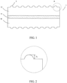
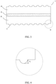
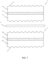
- the battery includes a cell and an electrolyte. Referring to FIG. 1 to FIG. 7 , where the cell includes
- the surfaces of the positive electrode film 12 and/or the negative electrode film 22 is provided with protrusions T, and the protrusions T provided on surfaces of the positive electrode film 12 have a height T c , the protrusions T provided on surfaces of the negative electrode film 22 have a height T a , and the thickness increase of the positive electrode film 12 is H c when the battery has a 100% state of charge (SOC) (that is, when the battery is fully charged for the first time), the thickness increase of the negative electrode film 22 is H a when the battery has a 100% state of charge (SOC) (that is, when the battery is fully charged for the first time), and the battery satisfies the condition that: 0.3 ⁇ T c + T a / H c + H a ⁇ 1 .
- the present disclosure solves the problem of battery expansion from the perspective of cell design. And on the surfaces of the positive electrode film and/or the negative electrode film is provided with protrusions, a height of the protrusions is designed according to a thickness increase of the corresponding electrode film, thereby reserving a space in advance for the volume expansion during the charging and discharging cycle of the positive and negative electrode plates, decreasing the expansive force of the battery throughout the life cycle, reducing pressure withstood by the module due to battery expansion, and further reducing the safety hazard of the power battery module structure.
- protrusions having appropriate height are provided on the surface of the positive electrode film and/or the negative electrode film, such that the battery can have both high safety and long cycle life. If the protrusions are not high enough to provide sufficient space during charging and discharging of the battery to accommodate the volume expansion of the positive and negative electrode plates, due to the expansive force of battery is still high, with a result that the cycle performance and safety performance of the battery will be poor.
- the protrusions are too high, although they can provide sufficient space to accommodate the volume expansion of the positive and negative electrode plates during charging and discharging of the battery, a too large volume expansion space may causes the electrolyte to be relatively insufficient, so that the electrolyte infiltration of the positive and negative electrode plates becomes poor, the polarization of the battery is increased during charging, and the transport path of the ions is too long during charging and discharging, which seriously affect the cycle life of the battery.
- the specific values of the height T c of the protrusions T provided on the surfaces of the positive electrode film 12 and the height T a of the protrusions T provided on the surfaces of the negative electrode film 22 are not particularly limited, as long as the ratio of the sum of the two to (H c +H a ) is between 0.3 to 1.
- the ratio of the sum of (T c +T a ) to the sum of (H c +H a ) is 0.3, 0.4, 0.5, 0.6, 0.7, 0.8, 0.9 or 1, including any and all ranges and subranges (for example 0.4 ⁇ 0.8 or 0.6 ⁇ -0.8).
- protrusions T may be provided only on the surfaces of the positive electrode film 12.
- the height T a of the protrusions T on the surfaces of the negative electrode film 22 is zero.
- the battery satisfies the condition that: 0.3 ⁇ T c /(H c +H a ) ⁇ 1, in an example, 0.4 ⁇ T c /(H c +H a ) ⁇ 0.8, and in another example, 0.6 ⁇ T c /H c +H a ) ⁇ 0.8.
- protrusions T may be provided only on the surfaces of the negative electrode film 22.
- the height T c of the protrusions T on the surfaces of the positive electrode film 12 is zero.
- the battery satisfies the condition that: 0.3 ⁇ T a /(H c +H a ) ⁇ 1, in an example, 0.4 ⁇ T a /(H c +H a ) ⁇ 0.8, and in another example, 0.6 ⁇ T a /(H c +H a ) ⁇ 0.8.
- protrusions T are provided on the surfaces of both the positive electrode film 12 and the negative electrode film 22, and T a and T c are both greater than zero.
- the battery satisfies the condition that: 0.3 ⁇ (T c +T a )/(H c+ H a ) ⁇ 1, in an example, 0.4 ⁇ (T c +T a )/(H c +H a ) ⁇ 0.8, and in another example, 0.6 ⁇ (T c +T a )/(H c +H a ) ⁇ 0.8.
- the protrusions T are only provided on the surfaces of the positive electrode film 12. This is because the cohesiveness of the negative electrode plate is usually low, and the negative electrode film is prone to falling off and dusting.
- the protrusions T on the surfaces of the positive electrode film 12 may have the same composition as that of the positive electrode film 12, and the protrusions T on the surfaces of the negative electrode film 22 may have the same composition as that of the negative electrode film 22.
- the protrusions T may be formed on the surfaces of the positive electrode film 12 and/or the negative electrode film 22 by roll compacting the positive electrode plate and/or the negative electrode plate using a counter roller having a protrusion structure after the electrode plates are cold pressed and before the procedure of winding (or laminating) to form the cell. In this way, not only the production costs can be reduced, but also the production efficiency is high.
- the protrusions T may be distributed, in the form of an array, on the surfaces of the positive electrode film 12 and/or the negative electrode film 22.
- the protrusions T are in a form of various regular or irregular shapes, and in an example, the protrusions are of a round, a semi-circular, a square, a rectangular or a trapezoidal.
- the projected area of the protrusions T on the surface of the positive electrode film 12 is 10%-60% of the total area of the positive electrode film 12.
- the bottom surface area of the protrusions overlaps with 10%-60% of the total area of the positive electrode film 12.
- the projected area of the protrusions T on the surfaces of the negative electrode film 22 is 10%-60% of the total area of the negative electrode film 22.
- the bottom surface area of the protrusions overlaps with 10%-60% of the total area of the negative electrode film 22.
- the positive electrode film 12 may be disposed on any one surface of the positive electrode current collector 11, or on both the upper and lower surfaces of the positive electrode current collector 11. That is, the positive electrode film 12 may be disposed on at least one surface of the positive electrode current collector 11 (similarly, at least one surface of the positive electrode film 12 is provided with protrusions.
- the types of the positive electrode active material are not particularly limited, and may be selected according to actual needs. Taking a lithium ion battery as an example, the positive electrode active material may be selected from one or more of the group consisting of a lithium transition metal oxide, and a compound obtained by adding an additional transition metal, non-transition metal or non-metal to a lithium transition metal oxide.
- the positive electrode active material may be selected from one or more of the group consisting of lithium cobalt oxide (LiCoO 2 ), lithium nickel oxide (LiNiO 2 ), lithium manganese oxide (LiMnO 2 ), lithium nickel manganese oxide (LiNi x Mn 2-x O 4 , 0 ⁇ x ⁇ 2), lithium ternary complex such as lithium nickel cobalt manganese oxide (i.e., NCM series, for example NCM 111, NCM 442, NCM 523, NCM 622 and NCM 811) and lithium nickel cobalt aluminum oxide (i.e., NCA series), and a lithium-containing phosphate having an olivine structure, in which the lithium-containing phosphate having an olivine structure may be further coated with a carbon coating layer.
- lithium cobalt oxide LiCoO 2
- LiNiO 2 lithium nickel oxide
- LiMnO 2 lithium manganese oxide
- LiNi x Mn 2-x O 4 lithium nickel manganese oxide
- NCA series
- the crystal volume of the lithium-containing phosphate material having an olivine structure is almost constant during the charge and discharge process, so that the volume expansion of the positive electrode plate due to charge and discharge can be reduced to the greatest extent.
- the primary particle size of the lithium-containing phosphate having an olivine structure is from 100 nm to 1 ⁇ m.
- the carbon-coated lithium-containing phosphate having an olivine structure can not only effectively ensure the electrical conductivity between the positive electrode active material particles, but also ensure the electrical conductivity between the positive electrode film and the positive electrode current collector.
- the existence of the carbon coating layer can also reduce the probability of dissolution of the transition metal (such as Fe element) from the positive electrode active material under the action of the electrolyte, thus preventing the increase of the expansive force of the battery caused by the deposition of the side reaction product.
- the thickness of the carbon coating layer may be, for example, 5 nm to 13 nm.
- the lithium-containing phosphate having an olivine structure may have a general formula of LiFe 1-x-y Mn x M' y PO 4 , in which 0 ⁇ x ⁇ 1, 0 ⁇ y ⁇ 0.1, 0 ⁇ x+y ⁇ 1, M' is selected from one or more of the group consisting of the transition metal elements other than Fe and Mn or non-transition metal elements, in an example M' is selected from one or more of the group consisting of Cr, Mg, Ti, Al, Zn, W, Nb, and Zr.
- the lithium-containing phosphate having an olivine structure is selected from one or more of the group consisting of lithium iron phosphate (LiFePO 4 ), lithium manganese phosphate (LiMnPO 4 ), and lithium manganese iron phosphate (LiFe 1-a Mn a PO 4 , 0 ⁇ a ⁇ 1).
- the positive electrode film 12 may further include a conductive agent and a binder.
- the types of the binder and the conductive agent are not particularly limited, and may be selected according to actual needs.
- the binder may be selected from one or more of the group consisting of polyvinylidene fluoride, polytetrafluoroethylene, polyvinylidene fluoride-tetrafluoroethylene-propylene terpolymer, polyvinylidene fluoride-hexafluoropropylene-tetrafluoroethylene terpolymer, tetrafluoroethylene-hexafluoropropylene copolymer, and a fluorine-containing acrylate resin.
- the conductive agent may be selected from one or more of the group consisting of conductive carbon black, superconducting carbon black, conductive graphite, acetylene black, ketjen black, graphene, and carbon nanotube
- the negative electrode film 22 may be disposed on any one of surfaces of the negative electrode current collector 21, or on both the upper and lower surfaces of the negative electrode current collector 21. That is, the negative electrode film 22 may be disposed on at least one surface of the negative electrode current collector 21 (similarly, at least one surface of the negative electrode film 22 is provided with protrusions.
- the types of the negative electrode active material are not particularly limited, and may be selected according to actual needs. Taking a lithium ion battery as an example, the negative electrode active material may be selected from one or more of the group consisting of graphite, soft carbon, hard carbon, carbon fibers, mesocarbon microbeads, silicon-based materials, tin-based materials, and lithium titanate.
- the graphite may be selected from one or more of artificial graphite and natural graphite;
- the silicon-based material may be selected from one or more of the group consisting of silicon, silicon oxide, silicon-carbon composites, and silicon alloys; and the tin-based material may be selected from one or more of tin, tin oxide and tin alloys.
- the negative electrode active material may be, for example, artificial graphite, and the artificial graphite may be, for example, non-needle coke secondary particles.
- the particle expansion of such artificial graphite tends to be isotropic, which can effectively reduce the expansion of the negative electrode plate in the thickness direction, thereby effectively reducing the expansive force of the battery.
- the artificial graphite has a degree of graphitization from 91% to 95%.
- the negative electrode film 22 may further include a binder and a conductive agent.
- the types of the binder and the conductive agent are not particularly limited, and may be selected according to actual needs.
- the binder may be selected from one or more of styrene-butadiene rubber emulsion (SBR) and sodium carboxymethyl cellulose (CMC).
- the conductive agent may be selected from one or more of conductive carbon black, superconducting carbon black, conductive graphite, acetylene black, ketjen black, graphene and carbon nanotubes.
- the type of the positive electrode current collector is not particularly limited, and may be selected according to actual needs.
- the positive electrode current collector may be an aluminum foil, a composite substrate having an aluminum layer on its surface, or an aluminum foil provided with a carbon layer on its surface.
- the type of the negative electrode current collector is not particularly limited, and may be selected according to actual needs.
- the negative electrode current collector may be a copper foil, a composite substrate having an copper layer on its surface, or a copper foil provided with a carbon layer on its surface.
- the separator 3 is made of polyethelene (PE) or polypropylene (PP), and the separator 3 has a thickness of 7 ⁇ m - 20 ⁇ m and a porosity of 35% - 45%. This not only ensures the mechanical manufacturability of the separator, but also ensures the good liquid absorption capacity and good electrochemical performance of the battery, thereby reducing the increase of the expansive force in the battery due to the accumulation of side reaction products.
- PE polyethelene
- PP polypropylene
- the electrolyte may include a lithium salt, an organic solvent, and an additive which is optionally added.
- the lithium salt may be an organic lithium salt or an inorganic lithium salt.
- the lithium salt may be selected from one or more of lithium hexafluorophosphate, lithium tetrafluoroborate, lithium perchlorate, lithium hexafluoroarsenate, lithium tetrafluorooxalato phosphate, LiN(SO 2 R F ) 2 , LiN(SO 2 F)(SO 2 R F ), bis(trifluoromethylsulfonyl)imide, lithium bis(fluorosulfonyl)imide, lithium bis(oxalato)borate, and lithium difluoro(oxalato)borate, in which the substituent R F is C n F 2n+1 , where n is an integer from 1 to 10.
- the lithium salt is lithium hexafluorophosphate.
- the lithium salt may have a concentration of 0.6 mol/L to 1.2 mol/L.
- the organic solvent may include a chain ester and a cyclic ester.
- the chain ester may be selected from one or more of the group consisting of dimethyl carbonate, diethyl carbonate, methyl ethyl carbonate, methyl propyl carbonate, methyl formate, ethyl formate, methyl acetate, ethyl acetate, propyl propionate, ethyl butyrate, ethyl propionate and propyl butyrate.
- the cyclic ester may be selected from one or more of the group consisting of ethylene carbonate, propylene carbonate, butylene carbonate, ethylene sulfite, propylene sulfite, ⁇ -butyrolactone and tetrahydrofuran.
- the organic solvent may further include different types of ionic liquids and the like.
- the additive may be vinylene carbonate, to ensure the stability of the solid electrolyte interphase film (i.e., SEI film) and reduce the increase of the expansive force of the battery due to the accumulation of side reaction products, and the content of the additive may be 1.5% to 2.5% of the total weight of the electrolyte.
- the battery further includes a case, and the case may be made of aluminum, steel or plastic, and have a thickness of 0.4 ⁇ m to 1.0 ⁇ m.
- the case mainly functions to ensure a certain rigidity, so as to exert a certain restrictive force on the expansion of the internal cell when the battery expands, and reduce the external force of the battery expansion.
- a certain amount of remain space can be reserved, which can provide a space for the expansion of the cell during the charge and discharge process, and reduces the overall expansive force of the battery. Where the amount of remain space can be set to 9%-11% of case volume.
- the initial thickness H 1 of the positive electrode film is 0.1 mm-0.4 mm.
- the initial thickness H 1 of the positive electrode film is any value between 0.1 mm and 0.4 mm, for example, but not limited to, 100 ⁇ m, 120 ⁇ m, 150 ⁇ m, 180 ⁇ m, 200 ⁇ m, 300. Mm or 400 ⁇ m, including any and all values and ranges and sub-ranges (eg 100 ⁇ m ⁇ 200 ⁇ m, 120 ⁇ m ⁇ 180 ⁇ m, etc.).
- the initial thickness H 2 of the negative electrode film is 0.07 mm-0.3 mm.
- the initial thickness H 2 of the negative electrode film is any value between 0.07 mm and 0.3 mm, for example, but not limited to, 70 ⁇ m, 80 ⁇ m, 100 ⁇ m, 115 ⁇ m, 130 ⁇ m, 150 ⁇ m, 200 ⁇ m, 300 ⁇ m, including any and all values and ranges and sub-ranges (eg 100 ⁇ m ⁇ 200 ⁇ m, 120 ⁇ m ⁇ 180 ⁇ m, etc.)
- the positive electrode slurry and/or negative electrode slurry may further include one or more of the group consisting of a conductive agent, a binder, a thickener, a solvent (especially an organic solvent) and the like.
- the conductive agent, the binder and the solvent are as described above and will not be described herein.
- the thickener may be selected from one or more of the group consisting of methylcellulose, hydroxypropylmehycellulose, sodium carboxymethyl cellulose, silicone gel, polyacrylamide, N-methylpyrrolidone, polyvinylpyrrolidone.
- the thickener is sodium carboxymethyl cellulose.
- the conductive agent, the binder, the thickener and the solvent will be selected according to actual needs, and the amounts of them are not particularly limited as long as the technical solution of the present disclosure can be achieved.
- the present disclosure is further described below in conjunction with examples. It is to be understood that these examples are merely illustrative of the present disclosure and are not intended to limit the scope of the present disclosure.
- the battery is only exemplified as a lithium ion battery in the examples, but the present disclosure is not limited thereto.
- the carbon-coated LiFePO 4 (where the thickness of the carbon coating is 6 nm, and LiFePO 4 is of a primary particle structure and has an average particle size of 120 nm) is used as a positive electrode active material, acetylene black is used as conductive agent, polyvinylidene fluoride is used as a binder, and N-methylpyrrolidone is used as a solvent.
- the above raw materials are mixed uniformly by stirring to form a positive electrode slurry, in which the weight ratio of the positive electrode active material, the conductive agent, and the binder is 94 : 4 : 2.
- the positive electrode slurry is uniformly coated onto both the upper and lower surfaces of a positive electrode current collector that is an aluminum foil, after drying at 85°C, cold pressing is performed, followed by cutting to form a positive electrode plate having a predetermined size.
- Artificial graphite (in the form of non-needle coke secondary particles, and has a degree of graphitization of 94%) is used as a negative electrode active material, acetylene black is used as a conductive agent, sodium carboxymethyl cellulose is used as a thickener, styrene-butadiene rubber is used as a binder, and deionized water is used as a solvent.
- the above raw materials are mixed uniformly by stirring to form a negative electrode slurry, in which the weight ratio of the negative electrode active material, the conductive agent, the thickener, and the binder is 95:1.5:0.4:3.1.
- the negative electrode slurry is uniformly coated onto both the upper and lower surfaces of a negative electrode current collector that is a copper foil, after drying at 85°C, cold pressing is performed, followed by cutting to form a negative electrode plate having a predetermined size.
- a thickness of a positive electrode film is 180 ⁇ m, and a thickness of a negative electrode film is 115 ⁇ m.
- Step 2 Test for thickness increase of positive electrode film and thickness increase of negative electrode film
- the positive electrode plate, the negative electrode plate prepared in step 1 and a separator are wound to obtain a cell, then the cell is placed in a case (which is a 0.8 ( ⁇ m-thick aluminum case, with a remain space being 10%), followed by assembling, injecting an electrolyte, formation, venting and other procedures, to obtain a battery to be tested.
- the battery to be tested is charged to 100% SOC, and disassembled after being disconnected from the power supply.
- a thickness increase of the positive electrode film is determined to be 3.6 ⁇ m
- a thickness increase of the negative electrode film is determined to be 23 ⁇ m.
- the separator is a polyethene (PE) film having a thickness of 12 ⁇ m and a porosity of 38%.
- the electrolyte is a solution in which a mixed organic solvents of ethylene carbonate (EC), dimethyl carbonate (DMC), diethyl carbonate (DEC), and methyl ethyl carbonate (EMC) at a weight ratio of 30:20:20:30, the lithium salt is LiPF 6 , having a concentration of 1.0 mol/L, and the additive in the electrolyte is vinylene carbonate with an addition amount of 2%.
- the positive electrode plate prepared in step 1 is roll compacted using a counter roller having a protrusion structure, to form protrusions that are 10 ⁇ m high on the surfaces of the positive electrode film. Then, as shown in FIG. 5 , the positive electrode plate having a protrusion structure is wound with the negative electrode plate prepared in step 1 and the separator to obtain a cell Then, the cell is placed in a case (which is a 0.8 ⁇ m thick aluminum case, with a remain space being 10%), and a battery is finally obtained by assembling, injecting an electrolyte, formation, venting, and other procedures.
- a case which is a 0.8 ⁇ m thick aluminum case, with a remain space being 10%
- the preparation process of the battery is the same as that of Example 1, except that the height of the protrusions on the surface of the positive electrode film is 15 ⁇ m.
- the preparation process of the battery is the same as that of Example 1, except that the height of the protrusions on the surface of the positive electrode film is 19 ⁇ m.
- the preparation process of the battery is the same as that of Example 1, except that the height of the protrusions on the surface of the positive electrode film is 22 ⁇ m.
- the preparation process of the battery is the same as that of Example 1, except that the height of the protrusions on the surface of the positive electrode film is 26 ⁇ m.
- the carbon-coated LiFePO 4 (where the thickness of the carbon coating is 6 nm, and LiFePO 4 is of a primary particle structure and has an average particle size of 120 nm) is used as a positive electrode active material, acetylene black is used as conductive agent, polyvinylidene fluoride is used as a binder, and N-methylpyrrolidone is used as a solvent.
- the above raw materials are mixed uniformly by stirring to form a positive electrode slurry, in which the weight ratio of the positive electrode active material, the conductive agent, and the binder is 94 : 4 : 2.
- the positive electrode slurry is uniformly coated onto both the upper and lower surfaces of a positive electrode current collector that is an aluminum foil, after drying at 85°C, cold pressing is performed, followed by cutting to form a positive electrode plate having a predetermined size.
- Artificial graphite (in the form of non-needle coke secondary particles, and has a degree of graphitization of 94%) is used as a negative electrode active material, acetylene black is used as a conductive agent, sodium carboxymethyl cellulose is used as a thickener, styrene-butadiene rubber is used as a binder, and deionized water is used as a solvent.
- the above raw materials are mixed uniformly by stirring to form a negative electrode slurry, in which the weight ratio of the negative electrode active material, the conductive agent, the thickener, and the binder is 95:1.5:0.4:3.1.
- the negative electrode slurry is uniformly coated onto both the upper and lower surfaces of a negative electrode current collector that is a copper foil, after drying at 85°C, cold pressing is performed, followed by cutting to form a negative electrode plate having a predetermined size.
- a thickness of a positive electrode film is 180 ⁇ m, and a thickness of a negative electrode film is 115 ⁇ m.
- Step 2 Test for thickness increase of positive electrode film and thickness increase of negative electrode film
- the positive electrode plate, the negative electrode plate prepared in step 1 and a separator are wound to obtain a cell, then the cell is placed in a case (which is a 0.8 ⁇ m thick aluminum case, with a remain space being 10%), followed by assembling, injecting an electrolyte, formation, venting and other procedures, to obtain a battery to be tested.
- the battery to be tested is charged to 100% SOC, and disassembled after being disconnected from the power supply.
- a thickness increase of the positive electrode film is determined to be 3.6 ⁇ m
- a thickness increase of the negative electrode film is determined to be 23 ⁇ m.
- the separator is a polypropylene (PP) film having a thickness of 20 ⁇ m and a porosity of 40%.
- the electrolyte is a solution in which a mixed organic solvents of ethylene carbonate (EC), dimethyl carbonate (DMC), diethyl carbonate (DEC), and methyl ethyl carbonate (EMC) at a weight ratio of 35:25:20:20, the lithium salt is LiPF 6 , having a concentration of 1.2 mol/L, and the additive in the electrolyte is vinylene carbonate with an addition amount of 2.5%.
- the negative electrode plate prepared in step 1 is roll compacted using a counter roller having a protrusion structure, to form protrusions that are 16 ⁇ m high on the surfaces of the negative electrode film. Then, as shown in FIG. 6 , the negative electrode plate having a protrusion structure is wound with the positive electrode plate prepared in step 1 and the separator to obtain a cell. Then, the cell is placed in a case (which is a 0.6 ⁇ m-thick aluminum case, with a remain space being 10%), and a battery is finally obtained by assembling, injecting an electrolyte, formation, venting, and other procedures.
- a case which is a 0.6 ⁇ m-thick aluminum case, with a remain space being 10%
- NCM523 (where NCM523 is of a secondary particle structure and has an average particle size of 10 nm) is used as a positive electrode active material, acetylene black is used as conductive agent, polyvinylidene fluoride is used as a binder, and N-methylpyrrolidone is used as a solvent.
- the above raw materials are mixed uniformly by stirring to form a positive electrode slurry, in which the weight ratio of the positive electrode active material, the conductive agent, and the binder is 94:4:2. Then the positive electrode slurry is uniformly coated onto both the upper and lower surfaces of a positive electrode current collector that is an aluminum foil, after drying at 85°C, cold pressing is performed, followed by cutting to form a positive electrode plate having a predetermined size.
- Artificial graphite (in the form of non-needle coke secondary particles, and has a degree of graphitization of 94%) is used as a negative electrode active material, acetylene black is used as a conductive agent, sodium carboxymethyl cellulose is used as a thickener, styrene-butadiene rubber is used as a binder, and deionized water is used as a solvent.
- the above raw materials are mixed uniformly by stirring to form a negative electrode slurry, in which the weight ratio of the negative electrode active material, the conductive agent, the thickener, and the binder is 95:1.5:0.4:3.1.
- the negative electrode slurry is uniformly coated onto both the upper and lower surfaces of a negative electrode current collector that is a copper foil, after drying at 85°C, cold pressing is performed, followed by cutting to form a negative electrode plate having a predetermined size.
- a thickness of a positive electrode film is 122 ⁇ m, and a thickness of a negative electrode film is 115 ⁇ m.
- Step 2 Test for thickness increase of positive electrode film and thickness increase of negative electrode film
- the positive electrode plate, the negative electrode plate prepared in step 1 and a separator are wound to obtain a cell, then the cell is placed in a case (which is a 0.8 ⁇ m-thick aluminum case, with a remain space being 10%), followed by assembling, injecting an electrolyte, formation, venting and other procedures, to obtain a battery to be tested.
- the battery to be tested is charged to 100% SOC, and disassembled after being disconnected from the power supply.
- a thickness increase of the positive electrode film is determined to be 6.1 ⁇ m
- a thickness increase of the negative electrode film is determined to be 23 ⁇ m.
- the separator is a PE film having a thickness of 12 ⁇ m and a porosity of 38%.
- the electrolyte is a solution in which a mixed organic solvents of ethylene carbonate (EC), dimethyl carbonate (DMC), diethyl carbonate (DEC), and methyl ethyl carbonate (EMC) at a weight ratio of 30:20:20:30, the lithium salt is LiPF 6 , having a concentration of 1.0 mol/L, and the additive in the electrolyte is vinylene carbonate with an addition amount of 2%.
- the positive electrode plate prepared in step 1 is roll compacted using a counter roller having a protrusion structure, to form protrusions that are 15 ⁇ m high on the surfaces of the positive electrode film. Then as shown in FIG.5 , the positive electrode plate having a protrusion structure is wound with the negative electrode plate prepared in step 1 and the separator to obtain a cell. Then, the cell is placed in a case (which is a 0.8 ⁇ m thick aluminum case, with a remain space being 10%), and a battery was finally obtained by assembling, injecting an electrolyte, formation, venting, and other procedures.
- a case which is a 0.8 ⁇ m thick aluminum case, with a remain space being 10%
- a mixture of NCM523 and NCM811 (where they both are of a secondary particle structure and have an average particle size of 10 ⁇ m) at a weight ratio of 1:1 is used as a positive electrode active material, acetylene black is used as conductive agent, polyvinylidene fluoride is used as a binder, and N-methylpyrrolidone is used as a solvent.
- the above raw materials are mixed uniformly by stirring to form a positive electrode slurry, in which the weight ratio of the positive electrode active material, the conductive agent, and the binder is 94:4:2. Then the positive electrode slurry is uniformly coated onto both the upper and lower surfaces of a positive electrode current collector that is an aluminum foil, after drying at 85°C, cold pressing is performed, followed by cutting to form a positive electrode plate having a predetermined size.
- Artificial graphite (in the form of non-needle coke secondary particles, and has a degree of graphitization of 94%) is used as a negative electrode active material, acetylene black is used as a conductive agent, sodium carboxymethyl cellulose is used as a thickener, styrene-butadiene rubber is used as a binder, and deionized water is used as a solvent.
- the above raw materials are mixed uniformly by stirring to form a negative electrode slurry, in which the weight ratio of the negative electrode active material, the conductive agent, the thickener, and the binder are 95:1.5:0.4:3.1.
- the negative electrode slurry is uniformly coated onto both the upper and lower surfaces of a negative electrode current collector that is a copper foil, after drying at 85°C, cold pressing is performed, followed by cutting to form a negative electrode plate having a predetermined size.
- the thickness of a positive electrode film is 122 ⁇ m, and the thickness of a negative electrode film is 115 ⁇ m.
- Step 2 Test for thickness increase of positive electrode film and thickness increase of negative electrode film
- the positive electrode plate and the negative electrode plate prepared in step 1 and a separator are wound to obtain a cell, then the cell is placed in a case (which is a 0.8 ⁇ m thick aluminum case, with a remain space being 10%), followed by assembling, injecting an electrolyte, formation, venting and other procedures, to obtain a battery to be tested.
- the battery to be tested is charged to 100% SOC, and disassembled after being disconnected from the power supply.
- the thickness increase of the positive electrode film is determined to be 7.3 ⁇ m
- the thickness increase of the negative electrode film is determined to be 23 ⁇ m.
- the separator is a PE film having a thickness of 12 ⁇ m and a porosity of 38%.
- the electrolyte is a solution in which an mixed organic solvents of ethylene carbonate (EC), dimethyl carbonate (DMC), diethyl carbonate (DEC), and methyl ethyl carbonate (EMC) at a weight ratio of 30:20:20:30, the lithium salt is LiPF 6 , having a concentration of 1.0 mol/L, and the additive in the electrolyte is vinylene carbonate with an addition amount of 2%.
- the positive electrode plate prepared in step 1 is roll compacted using a counter roller having a protrusion structure, to form protrusions that are 20 ⁇ m high on the surfaces of the positive electrode film. Then as shown in FIG. 5 , the positive electrode plate having a protrusion structure is wound with the negative electrode plate prepared in step 1 and the separator to obtain a cell. Then, the cell is placed in a case (which is a 0.8 ⁇ m thick aluminum case, with a remain space being 10%), and a battery is finally obtained by assembling, injecting an electrolyte, formation, venting, and other procedures.
- a case which is a 0.8 ⁇ m thick aluminum case, with a remain space being 10%
- NCM811 (where NCM811 is of a secondary particle structure, and has an average particle size of 10 ⁇ m) is used as a positive electrode active material, acetylene black is used as conductive agent, polyvinylidene fluoride is used as a binder, and N-methylpyrrolidone is used as a solvent.
- the above raw materials are mixed uniformly by stirring to form a positive electrode slurry, in which the weight ratio of the positive electrode active material, the conductive agent, and the binder is 94:4:2. Then the positive electrode slurry is uniformly coated onto both the upper and lower surfaces of a positive electrode current collector that is an aluminum foil, after drying at 85°C, cold pressing is performed, followed by cutting to form a positive electrode plate having a predetermined size.
- Artificial graphite (in the form of non-needle coke secondary particles, and has a degree of graphitization of 94%) is used as a negative electrode active material, acetylene black is used as a conductive agent, sodium carboxymethyl cellulose is used as a thickener, styrene-butadiene rubber is used as a binder, and deionized water is used as a solvent.
- the above raw materials are mixed uniformly by stirring to form a negative electrode slurry, in which the weight ratio of the negative electrode active material, the conductive agent, the thickener, and the binder is 95:1.5:0.4:3.1.
- the negative electrode slurry is uniformly coated onto both the upper and lower surfaces of a negative electrode current collector that is a copper foil, after drying at 85°C, cold pressing is performed, followed by cutting to form a negative electrode plate having a predetermined size.
- the thickness of a positive electrode film is 122 ⁇ m, and the thickness of a negative electrode film is 115 ⁇ m.
- Step 2 Test for thickness increase of positive electrode film and thickness increase of negative electrode film
- the positive electrode plate and the negative electrode plate prepared in step 1 and a separator are wound to obtain a cell, then the cell is placed in a case (which is a 0.8 ⁇ m thick aluminum case, with a remain space being 10%), followed by assembling, injecting an electrolyte, formation, venting and other procedures, to obtain a battery to be tested.
- the battery to be tested is charged to 100% SOC, and disassembled after being disconnected from the power supply.
- the thickness increase of the positive electrode film is determined to be 9.8 ⁇ m
- the thickness increase of the negative electrode film is determined to be 23 ⁇ m.
- the separator is a PE film having a thickness of 12 ⁇ m and a porosity of 38%.
- the electrolyte is a solution in which a mixed organic solvents of ethylene carbonate (EC), dimethyl carbonate (DMC), diethyl carbonate (DEC), and methyl ethyl carbonate (EMC) at a weight ratio of 30:20:20:30, the lithium salt is LiPF 6 , having a concentration of 1.0 mol/L, and the additive in the electrolyte is vinylene carbonate with an addition amount of 2%.
- the positive electrode plate prepared in step 1 is roll compacted using a counter roller having a protrusion structure, to form protrusions that are 22 ⁇ m high on the surfaces of the positive electrode film. Then as shown in FIG. 5 , the positive electrode plate having a protrusion structure is wound with the negative electrode plate prepared in step 1 and the separator to obtain a cell. Then, the cell is placed in a case (which is a 0.8 ⁇ m-thick aluminum case, with a remain space being 10%), and a battery is finally obtained by assembling, injecting an electrolyte, formation, venting, and other procedures.
- a case which is a 0.8 ⁇ m-thick aluminum case, with a remain space being 10%
- NCM811 (where NCM811 is of a secondary particle structure, and has an average particle size of 10 ⁇ m) is used as a positive electrode active material, acetylene black is used as conductive agent, polyvinylidene fluoride is used as a binder, and N-methylpyrrolidone is used as a solvent.
- the above raw materials are mixed uniformly by stirring to form a positive electrode slurry, in which the weight ratio of the positive electrode active material, the conductive agent, and the binder is 94:4:2. Then the positive electrode slurry is uniformly coated onto both the upper and lower surfaces of a positive electrode current collector that is an aluminum foil, after drying at 85°C, cold pressing is performed, followed by cutting to form a positive electrode plate having a predetermined size.
- Silicon dioxide is used as a negative electrode active material
- acetylene black is used as a conductive agent
- sodium carboxymethyl cellulose is used as a thickener
- styrene-butadiene rubber is used as a binder
- deionized water is used as a solvent.
- the above raw materials are mixed uniformly by stirring to form a negative electrode slurry, in which the weight ratio of the negative electrode active material, the conductive agent, the thickener, and the binder is 95:1.5:0.4:3.1.
- the negative electrode slurry is uniformly coated onto both the upper and lower surfaces of a negative electrode current collector that is a copper foil, after drying at 85°C, cold pressing is performed, followed by cutting to form a negative electrode plate having a predetermined size.
- the thickness of a positive electrode film is 122 ⁇ m, and the thickness of a negative electrode film is 115 ⁇ m.
- Step 2 Test for thickness increase of positive electrode film and thickness increase of negative electrode film
- the positive electrode plate and the negative electrode plate prepared in step 1 and a separator are wound to obtain a cell, then the cell is placed in a case (which is a 0.8 ⁇ m thick aluminum case, with a remain space being 10%), followed by assembling, injecting an electrolyte, formation, venting and other procedures, to obtain a battery to be tested.
- the battery to be tested is charged to 100% SOC, and disassembled after being disconnected from the power supply.
- the thickness increase of the positive electrode film is determined to be 9.8 ⁇ m
- the thickness increase of the negative electrode film is determined to be 57.5 ⁇ m.
- the separator is a PE film having a thickness of 12 ⁇ m and a porosity of 38%.
- the electrolyte is a solution of a mixed organic solvent in which ethylene carbonate (EC), dimethyl carbonate (DMC), diethyl carbonate (DEC), and methyl ethyl carbonate (EMC) at a weight ratio of 30:20:20:30, the lithium salt is LiPF 6 , having a concentration of 1.0 mol/L, and the additive in the electrolyte is vinylene carbonate with an addtion amount of 2%.
- the positive electrode plate and the negative electrode plate prepared in step 1 are respectively roll compacted using a counter roller having a protrusion structure, where the height of the protrusions on the surfaces of the positive electrode film is 10 ⁇ m and the height of the protrusions on the surface of the negative electrode film is 15 ⁇ m.
- the positive electrode plate having a protrusion structure, the negative electrode plate having a protrusion structure and the separator are wound to obtain a cell.
- the cell is placed in a case (which is a 0.8 ⁇ m-thick aluminum case, with a remain space being 10%), and a battery is finally obtained by assembling, injecting an electrolyte, formation, venting, and other procedures.
- NCM811 (where NCM811 is of a secondary particle structure, and has an average particle size of 10 ⁇ m) is used as a positive electrode active material, acetylene black is used as conductive agent, polyvinylidene fluoride is used as a binder, and N-methylpyrrolidone is used as a solvent.
- the above raw materials are mixed uniformly by stirring to form a positive electrode slurry, in which the weight ratio of the positive electrode active material, the conductive agent, and the binder is 94:4:2. Then the positive electrode slurry is uniformly coated onto both the upper and lower surfaces of a positive electrode current collector that is an aluminum foil, after drying at 85°C, cold pressing is performed, followed by cutting to form a positive electrode plate having a predetermined size.
- Silicon dioxide is used as a negative electrode active material
- acetylene black is used as a conductive agent
- sodium carboxymethyl cellulose is used as a thickener
- styrene-butadiene rubber is used as a binder
- deionized water is used as a solvent.
- the above materials are mixed uniformly by stirring to form a negative electrode slurry, in which the weight ratio of the negative electrode active material, the conductive agent, the thickener and the binder is 95:1.5:0.4:3.1.
- the negative electrode slurry is uniformly coated onto both the upper and lower surfaces of a negative electrode current collector that is a copper foil, after drying at 85°C, cold pressing is performed, followed by cuttingto form a negative electrode plate having a predetermined size.
- a thickness of a positive electrode film is 122 ⁇ m, and a thickness of a negative electrode film is 115 ⁇ m.
- Step 2 Test for thickness increase of positive electrode film and thickness increase of negative electrode film
- the positive electrode plate and the negative electrode plate prepared in step 1 and a separator are wound to obtain a cell, then the cell is placed in a case (which is a 0.8 ⁇ m thick aluminum case, with a remain space being 10%), followed by assembling, injecting an electrolyte, formation, venting and other procedures, to obtain a battery to be tested.
- the battery to be tested is charged to 100% SOC, and disassembled after being disconnected from the power supply.
- a thickness increase of the positive electrode film is determined to be 9.8 ⁇ m
- a thickness increase of the negative electrode film is determined to be 57.5 ⁇ m.
- the separator is a PE film having a thickness of 12 ⁇ m and a porosity of 38%.
- the electrolyte is a solution of a mixed organic solvent in which ethylene carbonate (EC), dimethyl carbonate (DMC), diethyl carbonate (DEC), and methyl ethyl carbonate (EMC) at a weight ratio of 30:20:20:30, the lithium salt is LiPF 6 , having a concentration of 1.0 mol/L, and the additive in the electrolyte is vinylene carbonate with an addition amount of 2%.
- the negative electrode plate prepared in step 1 is roll compacted using a counter roller having a protrusion structure, to form protrusions that are 21 ⁇ m high on the surface of the negative electrode film. Then as shown in FIG. 6 , the negative electrode plate having a protrusion structure is wound with the positive electrode plate prepared in step 1 and the separator to obtain a cell. Then, the cell is placed in a case (which is a 0.8 ⁇ m thick aluminum case, with a remain space being 10%), and a battery is finally obtained by assembling, injecting an electrolyte, formation, venting, and other procedures.
- a case which is a 0.8 ⁇ m thick aluminum case, with a remain space being 10%
- the preparation process of the battery is the same as that of Example 1, except that no protrusions are provided on the surface of the positive electrode film.
- the preparation process of the battery is the same as that of Example 7, except that no protrusions are provided on the surface of the positive electrode film.
- the preparation process of the battery is the same as that of Example 11, except that no protrusions are provided on the surface of the negative electrode film.
- the preparation process of the battery is the same as that of Example 1, except that the height of the protrusions on the surface of the positive electrode film is 40 ⁇ m.
- the preparation process of the battery is the same as that of Example 1, except that the height of the protrusions on the surface of the positive electrode film is 5 ⁇ m.
- the batteries prepared by Examples 1-11 and Comparative Examples 1-5 are subjected to a full-charging and full-discharging cycle test at 60°C with a charge and discharge rate of 1 C.
- a steel clamp is connected to a pressure sensor to monitor the expansive force data in real time, and the number of cycles when the battery capacity is attenuated to 80% and the expansive force of the battery are recorded.
Landscapes
- Chemical & Material Sciences (AREA)
- Chemical Kinetics & Catalysis (AREA)
- Electrochemistry (AREA)
- General Chemical & Material Sciences (AREA)
- Engineering & Computer Science (AREA)
- Manufacturing & Machinery (AREA)
- Physics & Mathematics (AREA)
- General Physics & Mathematics (AREA)
- Secondary Cells (AREA)
- Battery Electrode And Active Subsutance (AREA)
Claims (10)
- Batterie, die eine Zelle und einen Elektrolyt umfasst, wobei die Zelle umfasst:eine positive Elektrodenplatte (1), die umfasst:- einen positiven Elektrodenstromkollektor (11) und- einen positiven Elektrodenfilm (12), der auf mindestens einer Oberfläche des positiven Elektrodenstromkollektors (11) angeordnet ist und aus einem positiven aktiven Elektrodenmaterial besteht;eine negative Elektrodenplatte (2), die umfasst:- einen negativen Elektrodenstromkollektor (21) und- einen negativen Elektrodenfilm (22), der auf mindestens einer Oberfläche des negativen Elektrodenstromkollektors (21) angeordnet ist und aus einem negativen aktiven Elektrodenmaterial besteht;undeinen Separator (3), der zwischen der positiven Elektrodenplatte (1) und der negativen Elektrodenplatte (2) angeordnet ist;dadurch gekennzeichnet, dassin der Batterie mindestens eine Oberfläche des positiven Elektrodenfilms (12) und/oder des negativen Elektrodenfilms (22) mit Vorsprüngen (T) versehen ist; unddie Batterie die folgende Bedingung erfüllt: 0,4 ≤ (Tc + Ta)/(Hc + Ha) ≤0,8,wobei Tc eine Höhe der Vorsprünge (T) ist, die auf der mindestens einen Oberfläche des positiven Elektrodenfilms (12) bereitgestellt sind;Ta eine Höhe von Vorsprüngen (T) ist, die auf der mindestens einen Oberfläche des negativen Elektrodenfilms (22) bereitgestellt sind;Hc eine Dickenzunahme des positiven Elektrodenfilms (12) ist, wenn die Batterie ein erstes Mal einen Ladezustand von 100 % aufweist; undHa eine Dickenzunahme des negativen Elektrodenfilms (22) ist, wenn die Batterie ein erstes Mal einen Ladezustand von 100 % aufweist.
- Batterie nach Anspruch 1, dadurch gekennzeichnet, dass 0,6 ≤ (Tc + Ta)/(Hc + Ha) ≤ 0,8.
- Batterie nach einem der vorhergehenden Ansprüche, dadurch gekennzeichnet, dass die Vorsprünge (T) in einer Form eines Feldes auf mindestens einer Oberfläche des positiven Elektrodenfilms (12) und/oder des negativen Elektrodenfilms (22) verteilt sind.
- Batterie nach einem der vorhergehenden Ansprüche, dadurch gekennzeichnet, dass die Vorsprünge (T) die Form von verschiedenen gleichmäßigen oder ungleichmäßigen Formaten aufweisen und die Vorsprünge (T) vorzugsweise die Form eines runden, eines halbkreisförmigen, eines quadratischen, eines rechteckigen oder eines trapezförmigen Formats aufweisen.
- Batterie nach einem der vorhergehenden Ansprüche, dadurch gekennzeichnet, dass, wenn die Vorsprünge (T) auf der mindestens einen Oberfläche des positiven Elektrodenfilms (12) angeordnet sind, der projizierte Oberflächeninhalt der Vorsprünge (T) auf mindestens einer Oberfläche des positiven Elektrodenfilms (12) 10 % bis 60 % des Gesamtflächeninhalts des positiven Elektrodenfilms (12) beträgt.
- Batterie nach einem der vorhergehenden Ansprüche, dadurch gekennzeichnet, dass, wenn die Vorsprünge (T) auf der mindestens einen Oberfläche des negativen Elektrodenfilms (22) angeordnet sind, der projizierte Oberflächeninhalt der Vorsprünge (T) auf mindestens einer Oberfläche des negativen Elektrodenfilms (22) 10 % bis 60 % des Gesamtflächeninhalts des negativen Elektrodenfilms (22) beträgt.
- Batterie nach einem der vorhergehenden Ansprüche, dadurch gekennzeichnet, dass die Vorsprünge (T) nur auf mindestens einer Oberfläche des positiven Elektrodenfilms (12) angeordnet sind.
- Batterieherstellungsverfahren zur Herstellung einer Batterie nach einem der Ansprüche 1 bis 7, dadurch gekennzeichnet, dass das Verfahren die folgenden Schritte umfasst:Schritt 1: Auftragen einer positiven Elektrodenpaste, die ein positives aktives Elektrodenmaterial umfasst, auf einen positiven Elektrodenstromkollektor (11), Trocknen und Kaltpressen, um eine positive Elektrodenplatte (1) zu erhalten;Auftragen einer negativen Elektrodenpaste, die ein negatives aktives Elektrodenmaterial umfasst, auf einen negativen Elektrodenstromkollektor (21), Trocknen und Kaltpressen, um eine negative Elektrodenplatte (2) zu erhalten; undMessen einer Ausgangsdicke eines positiven Elektrodenfilms (12) der positiven Elektrodenplatte (1) als H1 und Messen einer Ausgangsdicke eines negativen Elektrodenfilms (22) der negativen Elektrodenplatte (2) als H2;Schritt 2: Zusammenbauen der positiven Elektrodenplatte (1) und der negativen Elektrodenplatte (2), die in Schritt 1 hergestellt wurden, eines Separators (3) und eines Elektrolyts in ein Gehäuse, um eine zu testende Batterie zu erhalten, Laden der zu testenden Batterie auf einen Ladezustand von 100 % und Auseinanderbauen der zu testenden Batterie nach ihrer Trennung von einer Stromversorgung; Messen einer Dicke des positiven Elektrodenfilms (12) als H1', der Dicke des negativen Elektrodenfilms (22) als H2' und Berechnen einer Dickenzunahme des positiven Elektrodenfilms (12) als Hc = H1' - H1 und einer Dickenzunahme des negativen Elektrodenfilms (22) als Ha = H2' - H2; undSchritt 3: Walzenkompaktieren der positiven Elektrodenplatte (1) und/oder der negativen Elektrodenplatte (2), die in Schritt 1 hergestellt wurden, unter Verwendung einer Gegenwalze, die eine Vorsprungsstruktur aufweist, um Vorsprünge (T) auf mindestens einer Oberfläche des positiven Elektrodenfilms (12) und/oder des negativen Elektrodenfilms (22) zu bilden, unter der Maßgabe, dass 0,4 ≤ (Tc + Ta)/(Hc + Ha) ≤ 0,8, wobei Tc eine Höhe der Vorsprünge (T) auf mindestens einer Oberfläche des positiven Elektrodenfilms (12) ist und Ta eine Höhe der Vorsprünge (T) auf mindestens einer Oberfläche des negativen Elektrodenfilms (22) ist; undWiederzusammenbauen der erhaltenen positiven Elektrodenplatte (1) und der negativen Elektrodenplatte (2), des Separators (3) und des Elektrolyts in ein Gehäuse, um eine Batterie zu erhalten.
- Verfahren zur Herstellung einer Batterie nach Anspruch 8, dadurch gekennzeichnet, dass im Schritt 1 die Ausgangsdicke H1 des positiven Elektrodenfilms (12) 0,1 mm bis 0,4 mm beträgt.
- Verfahren zur Herstellung einer Batterie nach Anspruch 8 oder 9, dadurch gekennzeichnet, dass im Schritt 1 die Ausgangsdicke H2 des negativen Elektrodenfilms (22) 0,07 mm bis 0,3 mm beträgt.
Applications Claiming Priority (1)
| Application Number | Priority Date | Filing Date | Title |
|---|---|---|---|
| CN201810510810.XA CN110534789B (zh) | 2018-05-24 | 2018-05-24 | 电池及其制备方法 |
Publications (2)
| Publication Number | Publication Date |
|---|---|
| EP3573145A1 EP3573145A1 (de) | 2019-11-27 |
| EP3573145B1 true EP3573145B1 (de) | 2022-02-23 |
Family
ID=66647295
Family Applications (1)
| Application Number | Title | Priority Date | Filing Date |
|---|---|---|---|
| EP19176515.5A Active EP3573145B1 (de) | 2018-05-24 | 2019-05-24 | Batterie und verfahren zur herstellung davon |
Country Status (3)
| Country | Link |
|---|---|
| US (1) | US11258091B2 (de) |
| EP (1) | EP3573145B1 (de) |
| CN (1) | CN110534789B (de) |
Families Citing this family (9)
| Publication number | Priority date | Publication date | Assignee | Title |
|---|---|---|---|---|
| WO2022091284A1 (ja) * | 2020-10-29 | 2022-05-05 | 日本電信電話株式会社 | 劣化検知装置および方法 |
| CN114447262B (zh) * | 2020-10-30 | 2024-07-23 | 北京小米移动软件有限公司 | 极片、涂布装置、电芯、电池包和电芯的制作方法 |
| JP7258064B2 (ja) * | 2021-03-11 | 2023-04-14 | プライムプラネットエナジー&ソリューションズ株式会社 | 二次電池用電極および該電極の製造方法 |
| CN113437354B (zh) * | 2021-06-26 | 2022-03-22 | 宁德时代新能源科技股份有限公司 | 电化学装置、电子装置 |
| CN117043983A (zh) * | 2021-11-08 | 2023-11-10 | 宁德时代新能源科技股份有限公司 | 负极极片及其制备方法、二次电池、电池模块、电池包及用电装置 |
| CN115995526B (zh) * | 2023-03-24 | 2024-03-12 | 宁德新能源科技有限公司 | 电极组件、电化学装置以及用电设备 |
| CN117637990B (zh) * | 2024-01-26 | 2024-04-26 | 宁德新能源科技有限公司 | 极片、电极组件及电池 |
| WO2025199737A1 (zh) * | 2024-03-26 | 2025-10-02 | 厦门新能安科技有限公司 | 二次电池和电子装置 |
| WO2025231840A1 (zh) * | 2024-05-10 | 2025-11-13 | 厦门新能安科技有限公司 | 二次电池和电子装置 |
Family Cites Families (10)
| Publication number | Priority date | Publication date | Assignee | Title |
|---|---|---|---|---|
| CN100341193C (zh) * | 2002-04-17 | 2007-10-03 | 松下电器产业株式会社 | 碱性蓄电池 |
| JP2005108521A (ja) * | 2003-09-29 | 2005-04-21 | Hitachi Maxell Ltd | 薄膜電極とその製造方法およびその薄膜電極を用いたリチウム二次電池 |
| EP2372821B1 (de) * | 2006-12-27 | 2014-04-30 | Panasonic Corporation | Batterie, Elektrode und dafür verwendeter Stromabnehmer |
| US20080248386A1 (en) | 2007-04-05 | 2008-10-09 | Obrovac Mark N | Electrodes with raised patterns |
| CN101436656B (zh) * | 2007-11-16 | 2010-10-06 | 比亚迪股份有限公司 | 一种锂离子电池负极及其制备方法以及锂离子电池 |
| JP5326340B2 (ja) * | 2008-04-28 | 2013-10-30 | ソニー株式会社 | 二次電池用負極、二次電池および電子機器 |
| JP5261029B2 (ja) * | 2008-05-29 | 2013-08-14 | 三洋電機株式会社 | 角形電池 |
| US20130236781A1 (en) * | 2012-03-06 | 2013-09-12 | Semiconductor Energy Laboratory Co., Ltd. | Negative electrode for secondary battery and secondary battery |
| US20140023898A1 (en) * | 2012-07-17 | 2014-01-23 | Sanyo Electric Co., Ltd. | Non-aqueous electrolyte secondary cell |
| US10720647B2 (en) * | 2016-01-29 | 2020-07-21 | Zeon Corporation | Binder composition for non-aqueous secondary battery electrode, slurry composition for non-aqueous secondary battery electrode, electrode for non-aqueous secondary battery, and non- aqueous secondary battery |
-
2018
- 2018-05-24 CN CN201810510810.XA patent/CN110534789B/zh active Active
-
2019
- 2019-05-23 US US16/420,773 patent/US11258091B2/en active Active
- 2019-05-24 EP EP19176515.5A patent/EP3573145B1/de active Active
Non-Patent Citations (1)
| Title |
|---|
| None * |
Also Published As
| Publication number | Publication date |
|---|---|
| CN110534789B (zh) | 2021-01-15 |
| US20190363391A1 (en) | 2019-11-28 |
| EP3573145A1 (de) | 2019-11-27 |
| US11258091B2 (en) | 2022-02-22 |
| CN110534789A (zh) | 2019-12-03 |
Similar Documents
| Publication | Publication Date | Title |
|---|---|---|
| EP3573145B1 (de) | Batterie und verfahren zur herstellung davon | |
| EP3761436B1 (de) | Lithium-ionen-sekundärbatterie und herstellungsverfahren dafür | |
| EP3800707B1 (de) | Sekundärbatterie und entsprechendes batteriemodul, batteriepack und gerät | |
| EP4089760A1 (de) | Elektrochemische vorrichtung und elektronische vorrichtung | |
| EP3916848B1 (de) | Sekundärbatterie, batteriemodul damit, batteriepack und vorrichtung | |
| EP4411857A1 (de) | Negativelektrodenfolie und herstellungsverfahren dafür, sekundärbatterie, batteriemodul, batteriepack und elektrische vorrichtung | |
| EP1826862B1 (de) | Sekundärbatterie mit nichtwässrigen Elektrolyten | |
| EP4145564A1 (de) | Sekundärbatterie und herstellungsverfahren dafür, batteriemodul mit sekundärbatterie, batteriepack und vorrichtung | |
| EP3435454B1 (de) | Lithium-ionen-batterie und positivaktivmaterial dafür | |
| US20230343933A1 (en) | Negative electrode active material, electrochemical apparatus, and electronic apparatus | |
| JP2023503688A (ja) | 二次電池及び当該二次電池を含む装置 | |
| EP3588629A1 (de) | Lithium-ionen-batterie | |
| EP4507019A1 (de) | Positivelektrodenfolie, sekundärbatterie und elektrische vorrichtung | |
| EP4175039A1 (de) | Negativelektrodenpolteil und sekundärbatterie, batteriepack, batteriemodul und elektrische vorrichtung | |
| EP4421897A1 (de) | Elektrochemische vorrichtung und elektronische vorrichtung damit | |
| EP4456230A1 (de) | Elektrochemische vorrichtung und elektronische vorrichtung damit | |
| EP4611056A1 (de) | Negativelektrodenfolie und elektrodenanordnung damit, batteriezelle, batterie und elektrische vorrichtung | |
| EP4246647A1 (de) | Elektrolyt, sekundärbatterie und elektrische vorrichtung | |
| EP4485602A1 (de) | Elektrochemische vorrichtung und elektrisches gerät damit | |
| EP4503173A1 (de) | Negativelektrodenplatte und herstellungsverfahren dafür, sekundärbatterie, batteriemodul, batteriepack und elektrische vorrichtung | |
| EP4148821A1 (de) | Sekundärbatterie und vorrichtung mit der sekundärbatterie | |
| EP4685861A1 (de) | Sekundärbatterie und elektrische vorrichtung | |
| KR102778712B1 (ko) | 복합 인조 흑연, 이의 제조 방법, 이를 함유한 이차 전지 및 전기 장치 | |
| US20260031397A1 (en) | Electrochemical apparatus and electronic apparatus | |
| EP4625574A1 (de) | Batterie |
Legal Events
| Date | Code | Title | Description |
|---|---|---|---|
| PUAI | Public reference made under article 153(3) epc to a published international application that has entered the european phase |
Free format text: ORIGINAL CODE: 0009012 |
|
| STAA | Information on the status of an ep patent application or granted ep patent |
Free format text: STATUS: REQUEST FOR EXAMINATION WAS MADE |
|
| 17P | Request for examination filed |
Effective date: 20190524 |
|
| AK | Designated contracting states |
Kind code of ref document: A1 Designated state(s): AL AT BE BG CH CY CZ DE DK EE ES FI FR GB GR HR HU IE IS IT LI LT LU LV MC MK MT NL NO PL PT RO RS SE SI SK SM TR |
|
| AX | Request for extension of the european patent |
Extension state: BA ME |
|
| STAA | Information on the status of an ep patent application or granted ep patent |
Free format text: STATUS: EXAMINATION IS IN PROGRESS |
|
| 17Q | First examination report despatched |
Effective date: 20200910 |
|
| GRAP | Despatch of communication of intention to grant a patent |
Free format text: ORIGINAL CODE: EPIDOSNIGR1 |
|
| STAA | Information on the status of an ep patent application or granted ep patent |
Free format text: STATUS: GRANT OF PATENT IS INTENDED |
|
| INTG | Intention to grant announced |
Effective date: 20210928 |
|
| GRAJ | Information related to disapproval of communication of intention to grant by the applicant or resumption of examination proceedings by the epo deleted |
Free format text: ORIGINAL CODE: EPIDOSDIGR1 |
|
| STAA | Information on the status of an ep patent application or granted ep patent |
Free format text: STATUS: EXAMINATION IS IN PROGRESS |
|
| GRAP | Despatch of communication of intention to grant a patent |
Free format text: ORIGINAL CODE: EPIDOSNIGR1 |
|
| STAA | Information on the status of an ep patent application or granted ep patent |
Free format text: STATUS: GRANT OF PATENT IS INTENDED |
|
| GRAS | Grant fee paid |
Free format text: ORIGINAL CODE: EPIDOSNIGR3 |
|
| INTC | Intention to grant announced (deleted) | ||
| GRAA | (expected) grant |
Free format text: ORIGINAL CODE: 0009210 |
|
| STAA | Information on the status of an ep patent application or granted ep patent |
Free format text: STATUS: THE PATENT HAS BEEN GRANTED |
|
| INTG | Intention to grant announced |
Effective date: 20220112 |
|
| AK | Designated contracting states |
Kind code of ref document: B1 Designated state(s): AL AT BE BG CH CY CZ DE DK EE ES FI FR GB GR HR HU IE IS IT LI LT LU LV MC MK MT NL NO PL PT RO RS SE SI SK SM TR |
|
| REG | Reference to a national code |
Ref country code: GB Ref legal event code: FG4D |
|
| REG | Reference to a national code |
Ref country code: CH Ref legal event code: EP |
|
| REG | Reference to a national code |
Ref country code: AT Ref legal event code: REF Ref document number: 1471134 Country of ref document: AT Kind code of ref document: T Effective date: 20220315 |
|
| REG | Reference to a national code |
Ref country code: IE Ref legal event code: FG4D |
|
| REG | Reference to a national code |
Ref country code: DE Ref legal event code: R096 Ref document number: 602019011780 Country of ref document: DE |
|
| REG | Reference to a national code |
Ref country code: SE Ref legal event code: TRGR |
|
| REG | Reference to a national code |
Ref country code: NL Ref legal event code: FP |
|
| REG | Reference to a national code |
Ref country code: LT Ref legal event code: MG9D |
|
| REG | Reference to a national code |
Ref country code: AT Ref legal event code: MK05 Ref document number: 1471134 Country of ref document: AT Kind code of ref document: T Effective date: 20220223 |
|
| PG25 | Lapsed in a contracting state [announced via postgrant information from national office to epo] |
Ref country code: RS Free format text: LAPSE BECAUSE OF FAILURE TO SUBMIT A TRANSLATION OF THE DESCRIPTION OR TO PAY THE FEE WITHIN THE PRESCRIBED TIME-LIMIT Effective date: 20220223 Ref country code: PT Free format text: LAPSE BECAUSE OF FAILURE TO SUBMIT A TRANSLATION OF THE DESCRIPTION OR TO PAY THE FEE WITHIN THE PRESCRIBED TIME-LIMIT Effective date: 20220623 Ref country code: NO Free format text: LAPSE BECAUSE OF FAILURE TO SUBMIT A TRANSLATION OF THE DESCRIPTION OR TO PAY THE FEE WITHIN THE PRESCRIBED TIME-LIMIT Effective date: 20220523 Ref country code: LT Free format text: LAPSE BECAUSE OF FAILURE TO SUBMIT A TRANSLATION OF THE DESCRIPTION OR TO PAY THE FEE WITHIN THE PRESCRIBED TIME-LIMIT Effective date: 20220223 Ref country code: HR Free format text: LAPSE BECAUSE OF FAILURE TO SUBMIT A TRANSLATION OF THE DESCRIPTION OR TO PAY THE FEE WITHIN THE PRESCRIBED TIME-LIMIT Effective date: 20220223 Ref country code: ES Free format text: LAPSE BECAUSE OF FAILURE TO SUBMIT A TRANSLATION OF THE DESCRIPTION OR TO PAY THE FEE WITHIN THE PRESCRIBED TIME-LIMIT Effective date: 20220223 Ref country code: BG Free format text: LAPSE BECAUSE OF FAILURE TO SUBMIT A TRANSLATION OF THE DESCRIPTION OR TO PAY THE FEE WITHIN THE PRESCRIBED TIME-LIMIT Effective date: 20220523 |
|
| PG25 | Lapsed in a contracting state [announced via postgrant information from national office to epo] |
Ref country code: PL Free format text: LAPSE BECAUSE OF FAILURE TO SUBMIT A TRANSLATION OF THE DESCRIPTION OR TO PAY THE FEE WITHIN THE PRESCRIBED TIME-LIMIT Effective date: 20220223 Ref country code: LV Free format text: LAPSE BECAUSE OF FAILURE TO SUBMIT A TRANSLATION OF THE DESCRIPTION OR TO PAY THE FEE WITHIN THE PRESCRIBED TIME-LIMIT Effective date: 20220223 Ref country code: GR Free format text: LAPSE BECAUSE OF FAILURE TO SUBMIT A TRANSLATION OF THE DESCRIPTION OR TO PAY THE FEE WITHIN THE PRESCRIBED TIME-LIMIT Effective date: 20220524 Ref country code: FI Free format text: LAPSE BECAUSE OF FAILURE TO SUBMIT A TRANSLATION OF THE DESCRIPTION OR TO PAY THE FEE WITHIN THE PRESCRIBED TIME-LIMIT Effective date: 20220223 Ref country code: AT Free format text: LAPSE BECAUSE OF FAILURE TO SUBMIT A TRANSLATION OF THE DESCRIPTION OR TO PAY THE FEE WITHIN THE PRESCRIBED TIME-LIMIT Effective date: 20220223 |
|
| PG25 | Lapsed in a contracting state [announced via postgrant information from national office to epo] |
Ref country code: IS Free format text: LAPSE BECAUSE OF FAILURE TO SUBMIT A TRANSLATION OF THE DESCRIPTION OR TO PAY THE FEE WITHIN THE PRESCRIBED TIME-LIMIT Effective date: 20220623 |
|
| PG25 | Lapsed in a contracting state [announced via postgrant information from national office to epo] |
Ref country code: SM Free format text: LAPSE BECAUSE OF FAILURE TO SUBMIT A TRANSLATION OF THE DESCRIPTION OR TO PAY THE FEE WITHIN THE PRESCRIBED TIME-LIMIT Effective date: 20220223 Ref country code: SK Free format text: LAPSE BECAUSE OF FAILURE TO SUBMIT A TRANSLATION OF THE DESCRIPTION OR TO PAY THE FEE WITHIN THE PRESCRIBED TIME-LIMIT Effective date: 20220223 Ref country code: RO Free format text: LAPSE BECAUSE OF FAILURE TO SUBMIT A TRANSLATION OF THE DESCRIPTION OR TO PAY THE FEE WITHIN THE PRESCRIBED TIME-LIMIT Effective date: 20220223 Ref country code: EE Free format text: LAPSE BECAUSE OF FAILURE TO SUBMIT A TRANSLATION OF THE DESCRIPTION OR TO PAY THE FEE WITHIN THE PRESCRIBED TIME-LIMIT Effective date: 20220223 Ref country code: DK Free format text: LAPSE BECAUSE OF FAILURE TO SUBMIT A TRANSLATION OF THE DESCRIPTION OR TO PAY THE FEE WITHIN THE PRESCRIBED TIME-LIMIT Effective date: 20220223 Ref country code: CZ Free format text: LAPSE BECAUSE OF FAILURE TO SUBMIT A TRANSLATION OF THE DESCRIPTION OR TO PAY THE FEE WITHIN THE PRESCRIBED TIME-LIMIT Effective date: 20220223 |
|
| REG | Reference to a national code |
Ref country code: DE Ref legal event code: R097 Ref document number: 602019011780 Country of ref document: DE |
|
| PG25 | Lapsed in a contracting state [announced via postgrant information from national office to epo] |
Ref country code: AL Free format text: LAPSE BECAUSE OF FAILURE TO SUBMIT A TRANSLATION OF THE DESCRIPTION OR TO PAY THE FEE WITHIN THE PRESCRIBED TIME-LIMIT Effective date: 20220223 |
|
| PLBE | No opposition filed within time limit |
Free format text: ORIGINAL CODE: 0009261 |
|
| REG | Reference to a national code |
Ref country code: CH Ref legal event code: PL |
|
| STAA | Information on the status of an ep patent application or granted ep patent |
Free format text: STATUS: NO OPPOSITION FILED WITHIN TIME LIMIT |
|
| REG | Reference to a national code |
Ref country code: BE Ref legal event code: MM Effective date: 20220531 |
|
| PG25 | Lapsed in a contracting state [announced via postgrant information from national office to epo] |
Ref country code: MC Free format text: LAPSE BECAUSE OF FAILURE TO SUBMIT A TRANSLATION OF THE DESCRIPTION OR TO PAY THE FEE WITHIN THE PRESCRIBED TIME-LIMIT Effective date: 20220223 Ref country code: LU Free format text: LAPSE BECAUSE OF NON-PAYMENT OF DUE FEES Effective date: 20220524 Ref country code: LI Free format text: LAPSE BECAUSE OF NON-PAYMENT OF DUE FEES Effective date: 20220531 Ref country code: CH Free format text: LAPSE BECAUSE OF NON-PAYMENT OF DUE FEES Effective date: 20220531 |
|
| 26N | No opposition filed |
Effective date: 20221124 |
|
| PG25 | Lapsed in a contracting state [announced via postgrant information from national office to epo] |
Ref country code: SI Free format text: LAPSE BECAUSE OF FAILURE TO SUBMIT A TRANSLATION OF THE DESCRIPTION OR TO PAY THE FEE WITHIN THE PRESCRIBED TIME-LIMIT Effective date: 20220223 |
|
| PG25 | Lapsed in a contracting state [announced via postgrant information from national office to epo] |
Ref country code: IE Free format text: LAPSE BECAUSE OF NON-PAYMENT OF DUE FEES Effective date: 20220524 |
|
| PG25 | Lapsed in a contracting state [announced via postgrant information from national office to epo] |
Ref country code: BE Free format text: LAPSE BECAUSE OF NON-PAYMENT OF DUE FEES Effective date: 20220531 |
|
| P01 | Opt-out of the competence of the unified patent court (upc) registered |
Effective date: 20230516 |
|
| PG25 | Lapsed in a contracting state [announced via postgrant information from national office to epo] |
Ref country code: HU Free format text: LAPSE BECAUSE OF FAILURE TO SUBMIT A TRANSLATION OF THE DESCRIPTION OR TO PAY THE FEE WITHIN THE PRESCRIBED TIME-LIMIT; INVALID AB INITIO Effective date: 20190524 |
|
| PG25 | Lapsed in a contracting state [announced via postgrant information from national office to epo] |
Ref country code: MK Free format text: LAPSE BECAUSE OF FAILURE TO SUBMIT A TRANSLATION OF THE DESCRIPTION OR TO PAY THE FEE WITHIN THE PRESCRIBED TIME-LIMIT Effective date: 20220223 Ref country code: CY Free format text: LAPSE BECAUSE OF FAILURE TO SUBMIT A TRANSLATION OF THE DESCRIPTION OR TO PAY THE FEE WITHIN THE PRESCRIBED TIME-LIMIT Effective date: 20220223 |
|
| REG | Reference to a national code |
Ref country code: DE Ref legal event code: R081 Ref document number: 602019011780 Country of ref document: DE Owner name: CONTEMPORARY AMPEREX TECHNOLOGY (HONG KONG) LI, HK Free format text: FORMER OWNER: CONTEMPORARY AMPEREX TECHNOLOGY CO., LIMITED, NINGDE CITY, FUJIAN, CN |
|
| REG | Reference to a national code |
Ref country code: NL Ref legal event code: PD Owner name: CONTEMPORARY AMPEREX TECHNOLOGY (HONG KONG) LIMITED; CN Free format text: DETAILS ASSIGNMENT: CHANGE OF OWNER(S), ASSIGNMENT; FORMER OWNER NAME: CONTEMPORARY AMPEREX TECHNOLOGY CO., LIMITED Effective date: 20240819 |
|
| REG | Reference to a national code |
Ref country code: GB Ref legal event code: 732E Free format text: REGISTERED BETWEEN 20240815 AND 20240821 |
|
| PG25 | Lapsed in a contracting state [announced via postgrant information from national office to epo] |
Ref country code: MT Free format text: LAPSE BECAUSE OF FAILURE TO SUBMIT A TRANSLATION OF THE DESCRIPTION OR TO PAY THE FEE WITHIN THE PRESCRIBED TIME-LIMIT Effective date: 20220223 |
|
| PGFP | Annual fee paid to national office [announced via postgrant information from national office to epo] |
Ref country code: NL Payment date: 20250409 Year of fee payment: 7 |
|
| PGFP | Annual fee paid to national office [announced via postgrant information from national office to epo] |
Ref country code: DE Payment date: 20250402 Year of fee payment: 7 |
|
| PGFP | Annual fee paid to national office [announced via postgrant information from national office to epo] |
Ref country code: IT Payment date: 20250422 Year of fee payment: 7 |
|
| PGFP | Annual fee paid to national office [announced via postgrant information from national office to epo] |
Ref country code: FR Payment date: 20250401 Year of fee payment: 7 |
|
| PG25 | Lapsed in a contracting state [announced via postgrant information from national office to epo] |
Ref country code: TR Free format text: LAPSE BECAUSE OF FAILURE TO SUBMIT A TRANSLATION OF THE DESCRIPTION OR TO PAY THE FEE WITHIN THE PRESCRIBED TIME-LIMIT Effective date: 20220223 |
|
| PGFP | Annual fee paid to national office [announced via postgrant information from national office to epo] |
Ref country code: SE Payment date: 20260312 Year of fee payment: 8 |
|
| PGFP | Annual fee paid to national office [announced via postgrant information from national office to epo] |
Ref country code: GB Payment date: 20260310 Year of fee payment: 8 |