EP3572663B1 - Filtre à combustible destiné au nettoyage du combustible pour un moteur à combustion interne - Google Patents
Filtre à combustible destiné au nettoyage du combustible pour un moteur à combustion interne Download PDFInfo
- Publication number
- EP3572663B1 EP3572663B1 EP19175381.3A EP19175381A EP3572663B1 EP 3572663 B1 EP3572663 B1 EP 3572663B1 EP 19175381 A EP19175381 A EP 19175381A EP 3572663 B1 EP3572663 B1 EP 3572663B1
- Authority
- EP
- European Patent Office
- Prior art keywords
- fuel
- water
- filter
- jet pump
- suction jet
- Prior art date
- Legal status (The legal status is an assumption and is not a legal conclusion. Google has not performed a legal analysis and makes no representation as to the accuracy of the status listed.)
- Active
Links
- 239000000446 fuel Substances 0.000 title claims description 137
- 238000002485 combustion reaction Methods 0.000 title claims description 31
- 238000004140 cleaning Methods 0.000 title claims description 6
- XLYOFNOQVPJJNP-UHFFFAOYSA-N water Substances O XLYOFNOQVPJJNP-UHFFFAOYSA-N 0.000 claims description 180
- 238000011045 prefiltration Methods 0.000 claims description 23
- 238000011144 upstream manufacturing Methods 0.000 claims description 7
- 230000002209 hydrophobic effect Effects 0.000 claims description 5
- 239000012528 membrane Substances 0.000 claims description 5
- 239000003380 propellant Substances 0.000 claims description 5
- 238000013022 venting Methods 0.000 claims description 2
- 230000005465 channeling Effects 0.000 claims 1
- 239000002828 fuel tank Substances 0.000 description 4
- 238000007599 discharging Methods 0.000 description 2
- 230000005484 gravity Effects 0.000 description 2
- 230000000717 retained effect Effects 0.000 description 2
- 229910000831 Steel Inorganic materials 0.000 description 1
- 230000001419 dependent effect Effects 0.000 description 1
- 230000008021 deposition Effects 0.000 description 1
- 239000002283 diesel fuel Substances 0.000 description 1
- 230000000694 effects Effects 0.000 description 1
- 238000000605 extraction Methods 0.000 description 1
- 230000009969 flowable effect Effects 0.000 description 1
- 230000008014 freezing Effects 0.000 description 1
- 238000007710 freezing Methods 0.000 description 1
- 238000012986 modification Methods 0.000 description 1
- 230000004048 modification Effects 0.000 description 1
- 238000005086 pumping Methods 0.000 description 1
- 239000010959 steel Substances 0.000 description 1
- 238000009423 ventilation Methods 0.000 description 1
Images

Classifications
-
- F—MECHANICAL ENGINEERING; LIGHTING; HEATING; WEAPONS; BLASTING
- F02—COMBUSTION ENGINES; HOT-GAS OR COMBUSTION-PRODUCT ENGINE PLANTS
- F02M—SUPPLYING COMBUSTION ENGINES IN GENERAL WITH COMBUSTIBLE MIXTURES OR CONSTITUENTS THEREOF
- F02M37/00—Apparatus or systems for feeding liquid fuel from storage containers to carburettors or fuel-injection apparatus; Arrangements for purifying liquid fuel specially adapted for, or arranged on, internal-combustion engines
- F02M37/22—Arrangements for purifying liquid fuel specially adapted for, or arranged on, internal-combustion engines, e.g. arrangements in the feeding system
- F02M37/24—Arrangements for purifying liquid fuel specially adapted for, or arranged on, internal-combustion engines, e.g. arrangements in the feeding system characterised by water separating means
-
- B—PERFORMING OPERATIONS; TRANSPORTING
- B01—PHYSICAL OR CHEMICAL PROCESSES OR APPARATUS IN GENERAL
- B01D—SEPARATION
- B01D29/00—Filters with filtering elements stationary during filtration, e.g. pressure or suction filters, not covered by groups B01D24/00 - B01D27/00; Filtering elements therefor
- B01D29/88—Filters with filtering elements stationary during filtration, e.g. pressure or suction filters, not covered by groups B01D24/00 - B01D27/00; Filtering elements therefor having feed or discharge devices
- B01D29/94—Filters with filtering elements stationary during filtration, e.g. pressure or suction filters, not covered by groups B01D24/00 - B01D27/00; Filtering elements therefor having feed or discharge devices for discharging the filter cake, e.g. chutes
- B01D29/945—Filters with filtering elements stationary during filtration, e.g. pressure or suction filters, not covered by groups B01D24/00 - B01D27/00; Filtering elements therefor having feed or discharge devices for discharging the filter cake, e.g. chutes for continuously discharging concentrated liquid
-
- B—PERFORMING OPERATIONS; TRANSPORTING
- B01—PHYSICAL OR CHEMICAL PROCESSES OR APPARATUS IN GENERAL
- B01D—SEPARATION
- B01D29/00—Filters with filtering elements stationary during filtration, e.g. pressure or suction filters, not covered by groups B01D24/00 - B01D27/00; Filtering elements therefor
- B01D29/96—Filters with filtering elements stationary during filtration, e.g. pressure or suction filters, not covered by groups B01D24/00 - B01D27/00; Filtering elements therefor in which the filtering elements are moved between filtering operations; Particular measures for removing or replacing the filtering elements; Transport systems for filters
-
- B—PERFORMING OPERATIONS; TRANSPORTING
- B01—PHYSICAL OR CHEMICAL PROCESSES OR APPARATUS IN GENERAL
- B01D—SEPARATION
- B01D36/00—Filter circuits or combinations of filters with other separating devices
- B01D36/003—Filters in combination with devices for the removal of liquids
-
- F—MECHANICAL ENGINEERING; LIGHTING; HEATING; WEAPONS; BLASTING
- F02—COMBUSTION ENGINES; HOT-GAS OR COMBUSTION-PRODUCT ENGINE PLANTS
- F02M—SUPPLYING COMBUSTION ENGINES IN GENERAL WITH COMBUSTIBLE MIXTURES OR CONSTITUENTS THEREOF
- F02M37/00—Apparatus or systems for feeding liquid fuel from storage containers to carburettors or fuel-injection apparatus; Arrangements for purifying liquid fuel specially adapted for, or arranged on, internal-combustion engines
- F02M37/0047—Layout or arrangement of systems for feeding fuel
- F02M37/0052—Details on the fuel return circuit; Arrangement of pressure regulators
-
- F—MECHANICAL ENGINEERING; LIGHTING; HEATING; WEAPONS; BLASTING
- F02—COMBUSTION ENGINES; HOT-GAS OR COMBUSTION-PRODUCT ENGINE PLANTS
- F02M—SUPPLYING COMBUSTION ENGINES IN GENERAL WITH COMBUSTIBLE MIXTURES OR CONSTITUENTS THEREOF
- F02M37/00—Apparatus or systems for feeding liquid fuel from storage containers to carburettors or fuel-injection apparatus; Arrangements for purifying liquid fuel specially adapted for, or arranged on, internal-combustion engines
- F02M37/02—Feeding by means of suction apparatus, e.g. by air flow through carburettors
- F02M37/025—Feeding by means of a liquid fuel-driven jet pump
-
- F—MECHANICAL ENGINEERING; LIGHTING; HEATING; WEAPONS; BLASTING
- F02—COMBUSTION ENGINES; HOT-GAS OR COMBUSTION-PRODUCT ENGINE PLANTS
- F02M—SUPPLYING COMBUSTION ENGINES IN GENERAL WITH COMBUSTIBLE MIXTURES OR CONSTITUENTS THEREOF
- F02M37/00—Apparatus or systems for feeding liquid fuel from storage containers to carburettors or fuel-injection apparatus; Arrangements for purifying liquid fuel specially adapted for, or arranged on, internal-combustion engines
- F02M37/04—Feeding by means of driven pumps
-
- F—MECHANICAL ENGINEERING; LIGHTING; HEATING; WEAPONS; BLASTING
- F02—COMBUSTION ENGINES; HOT-GAS OR COMBUSTION-PRODUCT ENGINE PLANTS
- F02M—SUPPLYING COMBUSTION ENGINES IN GENERAL WITH COMBUSTIBLE MIXTURES OR CONSTITUENTS THEREOF
- F02M37/00—Apparatus or systems for feeding liquid fuel from storage containers to carburettors or fuel-injection apparatus; Arrangements for purifying liquid fuel specially adapted for, or arranged on, internal-combustion engines
- F02M37/22—Arrangements for purifying liquid fuel specially adapted for, or arranged on, internal-combustion engines, e.g. arrangements in the feeding system
- F02M37/24—Arrangements for purifying liquid fuel specially adapted for, or arranged on, internal-combustion engines, e.g. arrangements in the feeding system characterised by water separating means
- F02M37/26—Arrangements for purifying liquid fuel specially adapted for, or arranged on, internal-combustion engines, e.g. arrangements in the feeding system characterised by water separating means with water detection means
-
- F—MECHANICAL ENGINEERING; LIGHTING; HEATING; WEAPONS; BLASTING
- F02—COMBUSTION ENGINES; HOT-GAS OR COMBUSTION-PRODUCT ENGINE PLANTS
- F02M—SUPPLYING COMBUSTION ENGINES IN GENERAL WITH COMBUSTIBLE MIXTURES OR CONSTITUENTS THEREOF
- F02M37/00—Apparatus or systems for feeding liquid fuel from storage containers to carburettors or fuel-injection apparatus; Arrangements for purifying liquid fuel specially adapted for, or arranged on, internal-combustion engines
- F02M37/22—Arrangements for purifying liquid fuel specially adapted for, or arranged on, internal-combustion engines, e.g. arrangements in the feeding system
- F02M37/32—Arrangements for purifying liquid fuel specially adapted for, or arranged on, internal-combustion engines, e.g. arrangements in the feeding system characterised by filters or filter arrangements
- F02M37/44—Filters structurally associated with pumps
-
- F—MECHANICAL ENGINEERING; LIGHTING; HEATING; WEAPONS; BLASTING
- F02—COMBUSTION ENGINES; HOT-GAS OR COMBUSTION-PRODUCT ENGINE PLANTS
- F02M—SUPPLYING COMBUSTION ENGINES IN GENERAL WITH COMBUSTIBLE MIXTURES OR CONSTITUENTS THEREOF
- F02M37/00—Apparatus or systems for feeding liquid fuel from storage containers to carburettors or fuel-injection apparatus; Arrangements for purifying liquid fuel specially adapted for, or arranged on, internal-combustion engines
- F02M37/22—Arrangements for purifying liquid fuel specially adapted for, or arranged on, internal-combustion engines, e.g. arrangements in the feeding system
- F02M37/54—Arrangements for purifying liquid fuel specially adapted for, or arranged on, internal-combustion engines, e.g. arrangements in the feeding system characterised by air purging means
-
- B—PERFORMING OPERATIONS; TRANSPORTING
- B01—PHYSICAL OR CHEMICAL PROCESSES OR APPARATUS IN GENERAL
- B01D—SEPARATION
- B01D2201/00—Details relating to filtering apparatus
- B01D2201/20—Pressure-related systems for filters
- B01D2201/204—Systems for applying vacuum to filters
- B01D2201/208—Systems for applying vacuum to filters by venturi systems
-
- B—PERFORMING OPERATIONS; TRANSPORTING
- B01—PHYSICAL OR CHEMICAL PROCESSES OR APPARATUS IN GENERAL
- B01D—SEPARATION
- B01D29/00—Filters with filtering elements stationary during filtration, e.g. pressure or suction filters, not covered by groups B01D24/00 - B01D27/00; Filtering elements therefor
- B01D29/50—Filters with filtering elements stationary during filtration, e.g. pressure or suction filters, not covered by groups B01D24/00 - B01D27/00; Filtering elements therefor with multiple filtering elements, characterised by their mutual disposition
- B01D29/56—Filters with filtering elements stationary during filtration, e.g. pressure or suction filters, not covered by groups B01D24/00 - B01D27/00; Filtering elements therefor with multiple filtering elements, characterised by their mutual disposition in series connection
Definitions
- Fuel filter for cleaning fuel for an internal combustion engine The invention relates to a fuel filter for cleaning fuel for an internal combustion engine.
- the invention further relates to an internal combustion engine with such a fuel filter and to a motor vehicle with such an internal combustion engine.
- Complex fuel filters are often constructed in two stages and include a pre-filter and a main filter with a delivery device connected in between, typically in the form of a suitable fuel pump.
- the fuel filter usually includes a water separator for separating the water contained in the fuel and - as part of the water separator - a water collection space for collecting the separated water.
- the water collection space can have a return line back into the fuel tank.
- a useful application for the return line from the water collection room to the tank is, for example, a level limiter for water in the water collection room.
- fuel filters operated on the suction side the pressure gradient in the direction of the return line in the filter must first be created.
- Such a complex filter device is used, for example, in EP1653075A2 disclosed.
- the basic idea of the invention is therefore to equip a fuel filter with a suction jet pump, which is fluidly connected to the water collection space of the water separator, so that by means of the suction jet pump, water and fuel can be removed from the water collection space, in which a negative pressure acts, into the return line, in which a higher pressure than in the water collecting space.
- the suction jet pump the pumping effect required for this is provided with the help of a propellant medium from the pressure-side main filter, which sucks in the water or fuel from the water collection space through pulse exchange and thus conveys it.
- the suction jet pump With the help of the suction jet pump, the pressure drop required for the transport of water or fuel from the water collection space can be easily generated without having to provide an external drive to drive the pump.
- a fuel filter according to the invention for cleaning fuel for an internal combustion engine comprises a main filter and a pre-filter arranged upstream of the main filter.
- the fuel can thus flow through the pre-filter and the main filter successively.
- the pre-filter includes a water separator for separating water present in the fuel.
- the water separator has a filter element in the form of a hydrophobic membrane for separating the water from the fuel and a water collecting space for collecting the separated water.
- the pre-filter is fluidly connected to the main filter by means of a conveying device, which conveys the fuel from the pre-filter into the main filter. The fuel sucked out of the pre-filter flows into the pre-filter from a suitable fuel reservoir after. After flowing through the main filter, the cleaned fuel is available for use in the internal combustion engine.
- the fuel filter device comprises a suction jet pump which is fluidly connected to the water collection space of the water separator for removing the water separated by means of the water separator or the water accumulated in the water collection space when the water exceeds a predetermined maximum fill level.
- a small portion flows continuously from the pressure area of the main filter via the suction jet pump into the return line and continuously conveys water or fuel from the water collection space in the negative pressure area of the pre-filter into the return line .
- the water collection chamber of the pre-filter is normally filled with fuel and vented. If the fuel pumped from the fuel reservoir contains water, this is retained in the water separator, flows into the water collection space and displaces the fuel present there. The water accumulates at the bottom of the water collection space due to the higher density of water to fuel and gradually fills the water collection space. Once the water collection space is full, the water should be drained using a water drain facility. Therefore, a water outlet fluidically connected to the suction jet pump is designed as an overflow, which determines a maximum possible filling level of water in the water collection space.
- the water collection space would overflow if water continued to be supplied, i.e. the water that continued to be supplied would not be retained and would be able to reach the engine together with the fuel. For this reason, the maximum water level in the water collection space must be limited.
- Another reason for setting a maximum permissible fill level for water in the water collecting space is the practical risk of the water freezing into ice with an increase in volume.
- the water freezes into ice there must be a volume portion filled with fuel in the water collection space that can be filled by the increased volume of the ice, whereby the fuel must be able to be displaced into other areas of the fuel filter via the inlet and outlet channels of the water collection space. If the container is completely filled with water, it may burst if the water freezes.
- the maximum filling level for water in the water collection space is limited by fluidically draining the connecting line water collection space - suction jet pump - return line at a defined level in the water collection space, thus creating an "overflow " for water.
- the water collects on the bottom of the housing due to the difference in density compared to the fuel. If more water is supplied and the filling level reaches the level of the discharge into the connecting line, then additional water is transported with the continuous volume flow through the connecting line from the water collection room via the suction jet pump into the return line.
- the level of discharge into the connecting pipe in the water collection room is chosen so that at this level and in normal operating situations, no water can get into the internal combustion engine along with the fuel and that the filter housing does not burst when the collected water freezes.
- the tank therefore serves as a buffer for the returned water for a transitional period.
- a fuel extractor is provided on the main filter, which communicates fluidly with the suction jet pump.
- the fuel flowing through the fuel extractor can be used as a driving medium for the suction jet pump, so that the effort required to drive the pump remains negligible. If you use the fuel extraction channel from the main filter to the suction jet pump at the same time as a ventilation channel for the fuel filter, the additional economic effort is also low.
- the fuel extractor communicates fluidly with an additional water separator via the suction jet pump.
- This additional water separator serves to separate the fuel, which acts as a propellant medium, from the water conveyed by the suction jet pump from the water separator or its water collection space.
- the volume flow from the connecting line water collection room - suction jet pump - return line into the tank via another water separator can conveniently be spatially separated from the actual fuel filter be arranged, i.e. preferably as a component in or on the tank.
- the volume of the water collection space could be made correspondingly small in this embodiment variant not according to the invention, and a water drain option could be dispensed with in the water collection space.
- a water separator fuel extractor is arranged in the additional water separator. This communicates fluidly with a fuel reservoir to remove the fuel present in the additional water separator. In this way, the separated water can be effectively freed from fuel residues, with the separated fuel being available for use in the internal combustion engine.
- the main filter can have a filter housing in which a filter element is arranged.
- the filter element divides the interior space delimited by the filter housing into a raw side and a clean side. Said fuel is withdrawn to the suction jet pump on the raw side, with fuel being withdrawn on the raw side in the upper area of the filter housing and the filter device is vented in the same channel.
- a fuel outlet for discharging the cleaned fuel from the fuel filter into an internal combustion engine is provided on the clean side of the filter.
- the filtered fuel can therefore be used in the internal combustion engine.
- the amount of fuel derived by the suction jet pump essentially corresponds to the amount of fuel that is permanently returned to the tank for automatic venting of the filter and therefore does not represent a disadvantage.
- the water separator has a separator housing through which the fuel can flow Housing interior limited.
- a hydrophobic membrane through which the fuel can flow is arranged in the housing interior to separate the water present in the fuel. Using such a hydrophobic membrane, high deposition rates can be achieved with a small space requirement
- the water collecting space is particularly preferably formed by a lower region of the housing interior with respect to the direction of gravity.
- the invention further relates to an internal combustion engine for a motor vehicle with cylinders, each of which has a combustion chamber. Each cylinder has at least one fuel injector for injecting fuel into the respective combustion chamber.
- the internal combustion engine includes a fuel supply for introducing the fuel into the fuel injectors.
- a fuel filter presented above is arranged upstream of the fuel supply. The advantages of the fuel filter explained above are therefore also transferred to the internal combustion engine according to the invention.
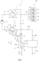
- Figure 1 illustrates schematically and in a circuit diagram-like representation the structure of the fuel filter 1 according to the invention for cleaning fuel K for an internal combustion engine.
- the fuel filter 1 comprises according to Figure 1 a main filter 3 and a pre-filter 2 arranged upstream of the main filter 3. Upstream of the pre-filter 2, a fuel reservoir 9 implemented as a fuel tank 10 with the fuel K to be cleaned is provided. The fuel K can flow through the two filters 2, 3 successively.
- the pre-filter 2 includes a water separator 4 for separating water W present in the fuel K.
- the water separator 4 has a separator housing 25, which delimits a housing interior 26 through which the fuel K can flow. In the housing interior 26 of the water separator 4 is one of the fuel K Flowable hydrophobic membrane 27 is arranged to separate the water W present in the fuel K.
- the water separator 4 also has a water collecting space 5 for collecting the water W separated in the water separator 4.
- the pre-filter 2 is fluidly connected to the main filter 3 by means of a conveyor device 18.
- the conveying device 18 conveys the fuel K from the pre-filter 2 into the main filter 3.
- the fuel filter 1 also includes a suction jet pump 6 which is fluidly connected to the water collecting space 5 of the water separator 4.
- the water collecting space 5 of the water separator 4 is formed by a direction of gravity S in the lower region 28 of the housing interior 26 when the water separator 4 is in a position of use.
- an outlet 29 is provided, which communicates fluidly with the suction jet pump 6.
- the maximum filling level for water in the water collecting space can be adjusted due to the distance between the outlet 29 and the deeper lower end of the housing interior 26. In this way, the water W can be pumped out of the water collection chamber 5 above a desired level using the suction jet pump 6.
- a water level sensor 34 which indicates the presence of water W to the outside, for example with an electrical signal, can be arranged below the outlet 29 and thus within the maximum filling height for water W and can indicate the presence of water W to the outside.
- a water drain 32 can be arranged on the housing bottom of the lower region 28 of the water collecting space 5 in order to discharge water from the fuel filter 1 into the environment.
- the main filter 3 includes a fuel extractor 7, which communicates fluidly with the suction jet pump 6. In this way, the fuel flowing through the fuel extractor 7 and supplied to the suction jet pump 6 can serve as a driving medium for the water W from the water separator 4 to be pumped by the suction jet pump 6.
- the main filter 3 has an in Figure 1 only a roughly schematic filter housing 12 is shown, in which a filter element 13, preferably replaceable, is arranged.
- the filter element 13 divides the housing interior 14 delimited by the filter housing 12 into a raw side 15 and a clean side 16.
- the suction jet pump 6 is arranged in a connecting line 7, which fluidly connects the raw side 15 of the main filter 3 to the additional water separator 8. The medium from this line drives the suction jet pump 6. Furthermore, the suction jet pump 6 is fluidly connected to the water collecting space 5 via a connecting line 19 and sucks the medium out of the water collecting space 5.
- Internal combustion engine 20 shown only in a rough schematic, has, for example, four cylinders 21, each of which has a combustion chamber 22. Each cylinder 21 has a fuel injector 23 for injecting the cleaned fuel K into the respective combustion chamber 22.
- the internal combustion engine 20 has a fuel supply 24 for introducing the fuel K into the fuel injectors 23.
- the fuel filter 1 according to the invention is thus arranged upstream of the fuel supply 24.
- the fuel reservoir 9 or the fuel tank 10 has a fuel outlet 11, which communicates with the internal combustion engine 2o via the pre-filter 2, the conveyor 18 and the main filter 3.
- the Figure 2 shows a modification not according to the invention Figure 1 .
- the fuel extractor 7 communicates fluidly via the suction jet pump 6 with an additional water separator 8 for separating the fuel acting as a propellant medium from the water W conveyed by the suction jet pump from the water separator 4 or its water collection chamber 5.
- a water separator fuel extractor can be in the additional water separator 8 30 may be arranged, which communicates fluidly with the fuel reservoir 9 or with the fuel tank 10 to remove the fuel present in the water separator 4.
- a water level sensor 34 for water can be arranged in the additional water separator 8 and can indicate the presence of water to the outside, for example with the aid of an electrical signal.
- a water drain 35 can be arranged in the lower area 36 of the additional water separator 8 in order to discharge water W from the filter system to the environment.
- a check valve 33 is provided in the connecting line 19 from the water collection space to the suction jet pump 6, which allows flow from the water collection space 5 to the suction jet pump 6 and blocks flow from the suction jet pump 6 to the water collection space 5.
Claims (5)
- Filtre à combustible (1) pour le nettoyage de combustible (K) pour un moteur à combustion interne (20),- avec un filtre principal (3) et avec un préfiltre (2) agencé en amont du filtre principal (3) qui peuvent être traversés de manière successive par le combustible (K),- dans lequel le préfiltre (2) présente un séparateur d'eau (4) pour la séparation d'eau (W) présente dans le combustible (K), séparateur d'eau qui comprend un espace collecteur d'eau (5) pour la collecte de l'eau séparée (W),- dans lequel le séparateur d'eau (4) présente un boîtier de séparateur (25) qui délimite un espace intérieur de boîtier de préfiltre (26) pouvant être traversé par le combustible (K),- dans lequel l'espace collecteur d'eau (5) du séparateur d'eau (4) est formé par une zone inférieure (28) en référence au sens de la gravité (5) de l'espace intérieur de boîtier de préfiltre (26), dans lequel une sortie d'eau (29) est prévue dans la zone inférieure (28) de l'espace collecteur d'eau (5),- dans lequel le filtre principal (3) présente un boîtier de filtre (12), dans lequel un élément de filtre (13) est agencé, élément qui divise un espace intérieur de boîtier de filtre principal (14) délimité par le boîtier de filtre (12) en un côté produit brut (15) et en un côté produit pur (16),- dans lequel dans le côté produit pur (16), une sortie de combustible (17) est présente pour l'évacuation du combustible (K) nettoyé hors du filtre de combustible (1) dans le moteur à combustion interne (20),- dans lequel le filtre à combustible (1) comprend une pompe à jet aspirant (6) reliée de manière fluidique à l'espace collecteur d'eau (5) pour l'évacuation de combustible (K) et/ou d'eau (W) hors de l'espace collecteur d'eau (5),- une extraction de combustible (7) est présente au niveau du filtre principal (3), extraction qui communique de manière fluidique avec la pompe à jet aspirant (6) de sorte que le combustible (K) s'écoulant à travers l'extraction de combustible (7) fonctionne comme fluide moteur de la pompe à jet aspirant (6), dans lequel l'extraction de combustible (7) du filtre principal (3) par rapport à la pompe à jet aspirant (6) sort du côté produit brut (15), et le même canal (7) est aussi utilisé pour la ventilation du filtre à combustible vers le réservoir,- dans lequel le préfiltre (2) est relié par le biais d'un appareil de refoulement (18) de manière fluidique au filtre principal (3), appareil qui refoule le combustible (K) du préfiltre (2) dans le filtre principal (3) et y établit une surpression, caractérisé en ce que- une membrane (27) hydrophobe pouvant être traversée par le combustible (K) est agencée dans l'espace intérieur de boîtier de préfiltre (26) pour la séparation de l'eau (W) contenue dans le combustible (K),- une sortie d'eau (29) est réalisée dans l'espace collecteur d'eau (5) pour la pompe à jet aspirant (6) comme trop-plein qui délimite la hauteur de remplissage pour de l'eau dans l'espace collecteur d'eau (5).
- Filtre à combustible selon la revendication 1,
caractérisé en ce que
un capteur de niveau d'eau (34) pour la détection d'eau (W) est prévu dans l'espace collecteur d'eau (5) en dessous de la sortie d'eau (29) par rapport à la pompe à jet aspirant (6). - Filtre à combustible selon l'une quelconque des revendications précédentes,
caractérisé en ce que
un clapet antiretour (33) est agencé dans une conduite de liaison (19) entre l'espace collecteur d'eau (5) et la pompe à jet aspirant (6), clapet qui permet l'écoulement de l'espace collecteur d'eau (5) à la pompe à jet aspirant (6) mais empêche l'écoulement de la pompe à jet aspirant (6) dans l'espace collecteur d'eau (5). - Moteur à combustion interne (20) pour un véhicule automobile,- avec des cylindres (21) dans lesquels respectivement une chambre de combustion (22) est présente,- dans lequel chaque cylindre (21) présente au moins un injecteur de combustible (23) pour l'injection du combustible (K) dans la chambre de combustion (22) respective,- dans lequel le moteur à combustion interne (20) comporte au moins une alimentation en combustible (24) pour l'introduction du combustible (K) dans les injecteurs de combustible (23),- dans lequel un filtre à combustible (1) selon l'une quelconque des revendications précédentes est agencé en amont de la au moins une alimentation en combustible (24).
- Véhicule automobile avec un moteur à combustion interne (20) selon la revendication 4.
Applications Claiming Priority (1)
| Application Number | Priority Date | Filing Date | Title |
|---|---|---|---|
| DE102018208082.8A DE102018208082A1 (de) | 2018-05-23 | 2018-05-23 | Kraftstofffilter zum Reinigen von Kraftstoff für eine Brennkraftmaschine |
Publications (2)
| Publication Number | Publication Date |
|---|---|
| EP3572663A1 EP3572663A1 (fr) | 2019-11-27 |
| EP3572663B1 true EP3572663B1 (fr) | 2024-01-24 |
Family
ID=66625089
Family Applications (1)
| Application Number | Title | Priority Date | Filing Date |
|---|---|---|---|
| EP19175381.3A Active EP3572663B1 (fr) | 2018-05-23 | 2019-05-20 | Filtre à combustible destiné au nettoyage du combustible pour un moteur à combustion interne |
Country Status (3)
| Country | Link |
|---|---|
| US (1) | US11020693B2 (fr) |
| EP (1) | EP3572663B1 (fr) |
| DE (1) | DE102018208082A1 (fr) |
Families Citing this family (1)
| Publication number | Priority date | Publication date | Assignee | Title |
|---|---|---|---|---|
| US11634316B2 (en) | 2020-09-30 | 2023-04-25 | Veeder-Root Company | Fuel storage and supply arrangement having fuel conditioning assembly |
Family Cites Families (5)
| Publication number | Priority date | Publication date | Assignee | Title |
|---|---|---|---|---|
| DE3740804C1 (en) * | 1987-12-02 | 1989-07-06 | Bosch Gmbh Robert | Fuel supply device for an internal combustion engine |
| US6444121B1 (en) | 1998-11-06 | 2002-09-03 | Stanadyne Corporation | Fuel filter system with water bleed and water trap |
| US7655140B2 (en) * | 2004-10-26 | 2010-02-02 | Cummins Filtration Ip Inc. | Automatic water drain for suction fuel water separators |
| SE528145C2 (sv) * | 2005-01-25 | 2006-09-12 | Scania Cv Ab | Motorfordon |
| DE102008038159A1 (de) * | 2008-08-18 | 2010-02-25 | Mahle International Gmbh | Kraftstofffilter |
-
2018
- 2018-05-23 DE DE102018208082.8A patent/DE102018208082A1/de active Pending
-
2019
- 2019-05-20 EP EP19175381.3A patent/EP3572663B1/fr active Active
- 2019-05-22 US US16/420,139 patent/US11020693B2/en active Active
Also Published As
| Publication number | Publication date |
|---|---|
| US20190358565A1 (en) | 2019-11-28 |
| EP3572663A1 (fr) | 2019-11-27 |
| DE102018208082A1 (de) | 2019-11-28 |
| US11020693B2 (en) | 2021-06-01 |
Similar Documents
| Publication | Publication Date | Title |
|---|---|---|
| EP2039893B1 (fr) | Dispositif et procédé de nettoyage de lubrifiants et circuit de lubrifiants | |
| WO2007134667A1 (fr) | Procédé et dispositif de séparation et de déchargement d'eau contenue dans des carburants liquides, notamment du gazole | |
| DE102014222463A1 (de) | Vorrichtung zur Wassereinspritzung und Verfahren zum Betrieb einer solchen | |
| EP1786539B1 (fr) | Filtre a carburant d'un moteur a combustion | |
| DE10138695A1 (de) | Vorrichtung zum Austragen von Wasser aus dem Kraftstoffsystem einer Brennkraftmaschine und Verfahren zu deren Betrieb | |
| EP1893864B1 (fr) | Dispositif d'alimentation en carburant | |
| DE2556169C3 (de) | Impulsgesteuerte Tropfenspritzeinrichtung | |
| EP3572663B1 (fr) | Filtre à combustible destiné au nettoyage du combustible pour un moteur à combustion interne | |
| WO2015172981A1 (fr) | Système hydraulique | |
| EP2681419A1 (fr) | Système d'alimentation en huile et procédé d'alimentation en huile d'un turbopropulseur | |
| DE112014001070B4 (de) | Kraftstoffsystem für einen Verbrennungsmotor, Verbrennungsmotor und Fahrzeug mit einem solchen Kraftstoffsystem und Verfahren zum Austausch eines Filterelements in einem Kraftstoffsystem | |
| EP2738031B1 (fr) | Système de réservoir pour un véhicule automobile | |
| DE102016205555A1 (de) | SCR-Vorrichtung mit Ventilanordnung | |
| EP3352877B1 (fr) | Dispositif filtrant avec pompe | |
| DE112014001066B4 (de) | Kraftstoffanlage für einen Verbrennungsmotor | |
| DE102012012182A1 (de) | Filtereinrichtung zum Filtern von Kraftstoff | |
| WO2015024649A1 (fr) | Système d'alimentation en carburant | |
| EP3516201B1 (fr) | Procédé de déshumidification d'un consommable ainsi que dispositif de déshumidification | |
| DE102017207855A1 (de) | Verfahren zum Betreiben eines Niederdruckkreislaufs in einem Kraftstoffeinspritzsystem sowie Niederdruckkreislauf | |
| DE112014002269B4 (de) | Kraftstoffsystem | |
| DE102016106312B4 (de) | Vorrichtung zum Absaugen von Altöl aus Fahrzeugmotoren | |
| DE102015210811A1 (de) | Vorrichtung und Verfahren zum Entleeren eines Wasserabscheiders einer Kraftstofffördereinrichtung, sowie ein Steuergerät und ein Werkstatt-Tester | |
| EP3382193B1 (fr) | Filtre à carburant permettant de filtrer le carburant dans un véhicule automobile et véhicule automobile pourvu d'un tel filtre à carburant | |
| DE593598C (de) | Pumpeinrichtung mit selbstansaugender Kreiselpumpe fuer atmosphaerische Saughoehe | |
| DE102004046574A1 (de) | Einrichtung zum Entgasen eines Filters, insbesondere eines Kraftstofffilters |
Legal Events
| Date | Code | Title | Description |
|---|---|---|---|
| PUAI | Public reference made under article 153(3) epc to a published international application that has entered the european phase |
Free format text: ORIGINAL CODE: 0009012 |
|
| STAA | Information on the status of an ep patent application or granted ep patent |
Free format text: STATUS: THE APPLICATION HAS BEEN PUBLISHED |
|
| AK | Designated contracting states |
Kind code of ref document: A1 Designated state(s): AL AT BE BG CH CY CZ DE DK EE ES FI FR GB GR HR HU IE IS IT LI LT LU LV MC MK MT NL NO PL PT RO RS SE SI SK SM TR |
|
| AX | Request for extension of the european patent |
Extension state: BA ME |
|
| STAA | Information on the status of an ep patent application or granted ep patent |
Free format text: STATUS: REQUEST FOR EXAMINATION WAS MADE |
|
| 17P | Request for examination filed |
Effective date: 20200518 |
|
| RBV | Designated contracting states (corrected) |
Designated state(s): AL AT BE BG CH CY CZ DE DK EE ES FI FR GB GR HR HU IE IS IT LI LT LU LV MC MK MT NL NO PL PT RO RS SE SI SK SM TR |
|
| STAA | Information on the status of an ep patent application or granted ep patent |
Free format text: STATUS: EXAMINATION IS IN PROGRESS |
|
| 17Q | First examination report despatched |
Effective date: 20200707 |
|
| STAA | Information on the status of an ep patent application or granted ep patent |
Free format text: STATUS: EXAMINATION IS IN PROGRESS |
|
| GRAP | Despatch of communication of intention to grant a patent |
Free format text: ORIGINAL CODE: EPIDOSNIGR1 |
|
| STAA | Information on the status of an ep patent application or granted ep patent |
Free format text: STATUS: GRANT OF PATENT IS INTENDED |
|
| INTG | Intention to grant announced |
Effective date: 20230922 |
|
| GRAS | Grant fee paid |
Free format text: ORIGINAL CODE: EPIDOSNIGR3 |
|
| GRAA | (expected) grant |
Free format text: ORIGINAL CODE: 0009210 |
|
| STAA | Information on the status of an ep patent application or granted ep patent |
Free format text: STATUS: THE PATENT HAS BEEN GRANTED |
|
| AK | Designated contracting states |
Kind code of ref document: B1 Designated state(s): AL AT BE BG CH CY CZ DE DK EE ES FI FR GB GR HR HU IE IS IT LI LT LU LV MC MK MT NL NO PL PT RO RS SE SI SK SM TR |
|
| REG | Reference to a national code |
Ref country code: GB Ref legal event code: FG4D Free format text: NOT ENGLISH |
|
| REG | Reference to a national code |
Ref country code: CH Ref legal event code: EP |
|
| REG | Reference to a national code |
Ref country code: DE Ref legal event code: R096 Ref document number: 502019010432 Country of ref document: DE |
|
| REG | Reference to a national code |
Ref country code: IE Ref legal event code: FG4D Free format text: LANGUAGE OF EP DOCUMENT: GERMAN |