EP3572551B1 - Verfahren zur beschichtung eines substrates mit einer hohlraumstruktur - Google Patents
Verfahren zur beschichtung eines substrates mit einer hohlraumstruktur Download PDFInfo
- Publication number
- EP3572551B1 EP3572551B1 EP19174701.3A EP19174701A EP3572551B1 EP 3572551 B1 EP3572551 B1 EP 3572551B1 EP 19174701 A EP19174701 A EP 19174701A EP 3572551 B1 EP3572551 B1 EP 3572551B1
- Authority
- EP
- European Patent Office
- Prior art keywords
- substrate
- gas flow
- layer
- diffusion layer
- cavity structure
- Prior art date
- Legal status (The legal status is an assumption and is not a legal conclusion. Google has not performed a legal analysis and makes no representation as to the accuracy of the status listed.)
- Active
Links
Images



Classifications
-
- C—CHEMISTRY; METALLURGY
- C23—COATING METALLIC MATERIAL; COATING MATERIAL WITH METALLIC MATERIAL; CHEMICAL SURFACE TREATMENT; DIFFUSION TREATMENT OF METALLIC MATERIAL; COATING BY VACUUM EVAPORATION, BY SPUTTERING, BY ION IMPLANTATION OR BY CHEMICAL VAPOUR DEPOSITION, IN GENERAL; INHIBITING CORROSION OF METALLIC MATERIAL OR INCRUSTATION IN GENERAL
- C23C—COATING METALLIC MATERIAL; COATING MATERIAL WITH METALLIC MATERIAL; SURFACE TREATMENT OF METALLIC MATERIAL BY DIFFUSION INTO THE SURFACE, BY CHEMICAL CONVERSION OR SUBSTITUTION; COATING BY VACUUM EVAPORATION, BY SPUTTERING, BY ION IMPLANTATION OR BY CHEMICAL VAPOUR DEPOSITION, IN GENERAL
- C23C4/00—Coating by spraying the coating material in the molten state, e.g. by flame, plasma or electric discharge
- C23C4/02—Pretreatment of the material to be coated, e.g. for coating on selected surface areas
-
- C—CHEMISTRY; METALLURGY
- C23—COATING METALLIC MATERIAL; COATING MATERIAL WITH METALLIC MATERIAL; CHEMICAL SURFACE TREATMENT; DIFFUSION TREATMENT OF METALLIC MATERIAL; COATING BY VACUUM EVAPORATION, BY SPUTTERING, BY ION IMPLANTATION OR BY CHEMICAL VAPOUR DEPOSITION, IN GENERAL; INHIBITING CORROSION OF METALLIC MATERIAL OR INCRUSTATION IN GENERAL
- C23C—COATING METALLIC MATERIAL; COATING MATERIAL WITH METALLIC MATERIAL; SURFACE TREATMENT OF METALLIC MATERIAL BY DIFFUSION INTO THE SURFACE, BY CHEMICAL CONVERSION OR SUBSTITUTION; COATING BY VACUUM EVAPORATION, BY SPUTTERING, BY ION IMPLANTATION OR BY CHEMICAL VAPOUR DEPOSITION, IN GENERAL
- C23C28/00—Coating for obtaining at least two superposed coatings either by methods not provided for in a single one of groups C23C2/00 - C23C26/00 or by combinations of methods provided for in subclasses C23C and C25C or C25D
- C23C28/30—Coatings combining at least one metallic layer and at least one inorganic non-metallic layer
- C23C28/34—Coatings combining at least one metallic layer and at least one inorganic non-metallic layer including at least one inorganic non-metallic material layer, e.g. metal carbide, nitride, boride, silicide layer and their mixtures, enamels, phosphates and sulphates
- C23C28/345—Coatings combining at least one metallic layer and at least one inorganic non-metallic layer including at least one inorganic non-metallic material layer, e.g. metal carbide, nitride, boride, silicide layer and their mixtures, enamels, phosphates and sulphates with at least one oxide layer
- C23C28/3455—Coatings combining at least one metallic layer and at least one inorganic non-metallic layer including at least one inorganic non-metallic material layer, e.g. metal carbide, nitride, boride, silicide layer and their mixtures, enamels, phosphates and sulphates with at least one oxide layer with a refractory ceramic layer, e.g. refractory metal oxide, ZrO2, rare earth oxides or a thermal barrier system comprising at least one refractory oxide layer
-
- C—CHEMISTRY; METALLURGY
- C23—COATING METALLIC MATERIAL; COATING MATERIAL WITH METALLIC MATERIAL; CHEMICAL SURFACE TREATMENT; DIFFUSION TREATMENT OF METALLIC MATERIAL; COATING BY VACUUM EVAPORATION, BY SPUTTERING, BY ION IMPLANTATION OR BY CHEMICAL VAPOUR DEPOSITION, IN GENERAL; INHIBITING CORROSION OF METALLIC MATERIAL OR INCRUSTATION IN GENERAL
- C23C—COATING METALLIC MATERIAL; COATING MATERIAL WITH METALLIC MATERIAL; SURFACE TREATMENT OF METALLIC MATERIAL BY DIFFUSION INTO THE SURFACE, BY CHEMICAL CONVERSION OR SUBSTITUTION; COATING BY VACUUM EVAPORATION, BY SPUTTERING, BY ION IMPLANTATION OR BY CHEMICAL VAPOUR DEPOSITION, IN GENERAL
- C23C10/00—Solid state diffusion of only metal elements or silicon into metallic material surfaces
- C23C10/28—Solid state diffusion of only metal elements or silicon into metallic material surfaces using solids, e.g. powders, pastes
- C23C10/34—Embedding in a powder mixture, i.e. pack cementation
- C23C10/36—Embedding in a powder mixture, i.e. pack cementation only one element being diffused
- C23C10/48—Aluminising
-
- C—CHEMISTRY; METALLURGY
- C23—COATING METALLIC MATERIAL; COATING MATERIAL WITH METALLIC MATERIAL; CHEMICAL SURFACE TREATMENT; DIFFUSION TREATMENT OF METALLIC MATERIAL; COATING BY VACUUM EVAPORATION, BY SPUTTERING, BY ION IMPLANTATION OR BY CHEMICAL VAPOUR DEPOSITION, IN GENERAL; INHIBITING CORROSION OF METALLIC MATERIAL OR INCRUSTATION IN GENERAL
- C23C—COATING METALLIC MATERIAL; COATING MATERIAL WITH METALLIC MATERIAL; SURFACE TREATMENT OF METALLIC MATERIAL BY DIFFUSION INTO THE SURFACE, BY CHEMICAL CONVERSION OR SUBSTITUTION; COATING BY VACUUM EVAPORATION, BY SPUTTERING, BY ION IMPLANTATION OR BY CHEMICAL VAPOUR DEPOSITION, IN GENERAL
- C23C10/00—Solid state diffusion of only metal elements or silicon into metallic material surfaces
- C23C10/60—After-treatment
-
- C—CHEMISTRY; METALLURGY
- C23—COATING METALLIC MATERIAL; COATING MATERIAL WITH METALLIC MATERIAL; CHEMICAL SURFACE TREATMENT; DIFFUSION TREATMENT OF METALLIC MATERIAL; COATING BY VACUUM EVAPORATION, BY SPUTTERING, BY ION IMPLANTATION OR BY CHEMICAL VAPOUR DEPOSITION, IN GENERAL; INHIBITING CORROSION OF METALLIC MATERIAL OR INCRUSTATION IN GENERAL
- C23C—COATING METALLIC MATERIAL; COATING MATERIAL WITH METALLIC MATERIAL; SURFACE TREATMENT OF METALLIC MATERIAL BY DIFFUSION INTO THE SURFACE, BY CHEMICAL CONVERSION OR SUBSTITUTION; COATING BY VACUUM EVAPORATION, BY SPUTTERING, BY ION IMPLANTATION OR BY CHEMICAL VAPOUR DEPOSITION, IN GENERAL
- C23C28/00—Coating for obtaining at least two superposed coatings either by methods not provided for in a single one of groups C23C2/00 - C23C26/00 or by combinations of methods provided for in subclasses C23C and C25C or C25D
- C23C28/30—Coatings combining at least one metallic layer and at least one inorganic non-metallic layer
- C23C28/32—Coatings combining at least one metallic layer and at least one inorganic non-metallic layer including at least one pure metallic layer
- C23C28/321—Coatings combining at least one metallic layer and at least one inorganic non-metallic layer including at least one pure metallic layer with at least one metal alloy layer
-
- C—CHEMISTRY; METALLURGY
- C23—COATING METALLIC MATERIAL; COATING MATERIAL WITH METALLIC MATERIAL; CHEMICAL SURFACE TREATMENT; DIFFUSION TREATMENT OF METALLIC MATERIAL; COATING BY VACUUM EVAPORATION, BY SPUTTERING, BY ION IMPLANTATION OR BY CHEMICAL VAPOUR DEPOSITION, IN GENERAL; INHIBITING CORROSION OF METALLIC MATERIAL OR INCRUSTATION IN GENERAL
- C23C—COATING METALLIC MATERIAL; COATING MATERIAL WITH METALLIC MATERIAL; SURFACE TREATMENT OF METALLIC MATERIAL BY DIFFUSION INTO THE SURFACE, BY CHEMICAL CONVERSION OR SUBSTITUTION; COATING BY VACUUM EVAPORATION, BY SPUTTERING, BY ION IMPLANTATION OR BY CHEMICAL VAPOUR DEPOSITION, IN GENERAL
- C23C28/00—Coating for obtaining at least two superposed coatings either by methods not provided for in a single one of groups C23C2/00 - C23C26/00 or by combinations of methods provided for in subclasses C23C and C25C or C25D
- C23C28/30—Coatings combining at least one metallic layer and at least one inorganic non-metallic layer
- C23C28/32—Coatings combining at least one metallic layer and at least one inorganic non-metallic layer including at least one pure metallic layer
- C23C28/321—Coatings combining at least one metallic layer and at least one inorganic non-metallic layer including at least one pure metallic layer with at least one metal alloy layer
- C23C28/3215—Coatings combining at least one metallic layer and at least one inorganic non-metallic layer including at least one pure metallic layer with at least one metal alloy layer at least one MCrAlX layer
-
- C—CHEMISTRY; METALLURGY
- C23—COATING METALLIC MATERIAL; COATING MATERIAL WITH METALLIC MATERIAL; CHEMICAL SURFACE TREATMENT; DIFFUSION TREATMENT OF METALLIC MATERIAL; COATING BY VACUUM EVAPORATION, BY SPUTTERING, BY ION IMPLANTATION OR BY CHEMICAL VAPOUR DEPOSITION, IN GENERAL; INHIBITING CORROSION OF METALLIC MATERIAL OR INCRUSTATION IN GENERAL
- C23C—COATING METALLIC MATERIAL; COATING MATERIAL WITH METALLIC MATERIAL; SURFACE TREATMENT OF METALLIC MATERIAL BY DIFFUSION INTO THE SURFACE, BY CHEMICAL CONVERSION OR SUBSTITUTION; COATING BY VACUUM EVAPORATION, BY SPUTTERING, BY ION IMPLANTATION OR BY CHEMICAL VAPOUR DEPOSITION, IN GENERAL
- C23C4/00—Coating by spraying the coating material in the molten state, e.g. by flame, plasma or electric discharge
- C23C4/01—Selective coating, e.g. pattern coating, without pre-treatment of the material to be coated
-
- C—CHEMISTRY; METALLURGY
- C23—COATING METALLIC MATERIAL; COATING MATERIAL WITH METALLIC MATERIAL; CHEMICAL SURFACE TREATMENT; DIFFUSION TREATMENT OF METALLIC MATERIAL; COATING BY VACUUM EVAPORATION, BY SPUTTERING, BY ION IMPLANTATION OR BY CHEMICAL VAPOUR DEPOSITION, IN GENERAL; INHIBITING CORROSION OF METALLIC MATERIAL OR INCRUSTATION IN GENERAL
- C23C—COATING METALLIC MATERIAL; COATING MATERIAL WITH METALLIC MATERIAL; SURFACE TREATMENT OF METALLIC MATERIAL BY DIFFUSION INTO THE SURFACE, BY CHEMICAL CONVERSION OR SUBSTITUTION; COATING BY VACUUM EVAPORATION, BY SPUTTERING, BY ION IMPLANTATION OR BY CHEMICAL VAPOUR DEPOSITION, IN GENERAL
- C23C4/00—Coating by spraying the coating material in the molten state, e.g. by flame, plasma or electric discharge
- C23C4/04—Coating by spraying the coating material in the molten state, e.g. by flame, plasma or electric discharge characterised by the coating material
- C23C4/10—Oxides, borides, carbides, nitrides or silicides; Mixtures thereof
- C23C4/11—Oxides
-
- C—CHEMISTRY; METALLURGY
- C23—COATING METALLIC MATERIAL; COATING MATERIAL WITH METALLIC MATERIAL; CHEMICAL SURFACE TREATMENT; DIFFUSION TREATMENT OF METALLIC MATERIAL; COATING BY VACUUM EVAPORATION, BY SPUTTERING, BY ION IMPLANTATION OR BY CHEMICAL VAPOUR DEPOSITION, IN GENERAL; INHIBITING CORROSION OF METALLIC MATERIAL OR INCRUSTATION IN GENERAL
- C23C—COATING METALLIC MATERIAL; COATING MATERIAL WITH METALLIC MATERIAL; SURFACE TREATMENT OF METALLIC MATERIAL BY DIFFUSION INTO THE SURFACE, BY CHEMICAL CONVERSION OR SUBSTITUTION; COATING BY VACUUM EVAPORATION, BY SPUTTERING, BY ION IMPLANTATION OR BY CHEMICAL VAPOUR DEPOSITION, IN GENERAL
- C23C4/00—Coating by spraying the coating material in the molten state, e.g. by flame, plasma or electric discharge
- C23C4/12—Coating by spraying the coating material in the molten state, e.g. by flame, plasma or electric discharge characterised by the method of spraying
- C23C4/134—Plasma spraying
-
- C—CHEMISTRY; METALLURGY
- C23—COATING METALLIC MATERIAL; COATING MATERIAL WITH METALLIC MATERIAL; CHEMICAL SURFACE TREATMENT; DIFFUSION TREATMENT OF METALLIC MATERIAL; COATING BY VACUUM EVAPORATION, BY SPUTTERING, BY ION IMPLANTATION OR BY CHEMICAL VAPOUR DEPOSITION, IN GENERAL; INHIBITING CORROSION OF METALLIC MATERIAL OR INCRUSTATION IN GENERAL
- C23C—COATING METALLIC MATERIAL; COATING MATERIAL WITH METALLIC MATERIAL; SURFACE TREATMENT OF METALLIC MATERIAL BY DIFFUSION INTO THE SURFACE, BY CHEMICAL CONVERSION OR SUBSTITUTION; COATING BY VACUUM EVAPORATION, BY SPUTTERING, BY ION IMPLANTATION OR BY CHEMICAL VAPOUR DEPOSITION, IN GENERAL
- C23C4/00—Coating by spraying the coating material in the molten state, e.g. by flame, plasma or electric discharge
- C23C4/12—Coating by spraying the coating material in the molten state, e.g. by flame, plasma or electric discharge characterised by the method of spraying
- C23C4/137—Spraying in vacuum or in an inert atmosphere
-
- F—MECHANICAL ENGINEERING; LIGHTING; HEATING; WEAPONS; BLASTING
- F23—COMBUSTION APPARATUS; COMBUSTION PROCESSES
- F23R—GENERATING COMBUSTION PRODUCTS OF HIGH PRESSURE OR HIGH VELOCITY, e.g. GAS-TURBINE COMBUSTION CHAMBERS
- F23R3/00—Continuous combustion chambers using liquid or gaseous fuel
- F23R3/002—Wall structures
-
- F—MECHANICAL ENGINEERING; LIGHTING; HEATING; WEAPONS; BLASTING
- F23—COMBUSTION APPARATUS; COMBUSTION PROCESSES
- F23R—GENERATING COMBUSTION PRODUCTS OF HIGH PRESSURE OR HIGH VELOCITY, e.g. GAS-TURBINE COMBUSTION CHAMBERS
- F23R3/00—Continuous combustion chambers using liquid or gaseous fuel
- F23R3/005—Combined with pressure or heat exchangers
-
- F—MECHANICAL ENGINEERING; LIGHTING; HEATING; WEAPONS; BLASTING
- F23—COMBUSTION APPARATUS; COMBUSTION PROCESSES
- F23R—GENERATING COMBUSTION PRODUCTS OF HIGH PRESSURE OR HIGH VELOCITY, e.g. GAS-TURBINE COMBUSTION CHAMBERS
- F23R3/00—Continuous combustion chambers using liquid or gaseous fuel
- F23R3/02—Continuous combustion chambers using liquid or gaseous fuel characterised by the air-flow or gas-flow configuration
- F23R3/04—Air inlet arrangements
- F23R3/06—Arrangement of apertures along the flame tube
-
- F—MECHANICAL ENGINEERING; LIGHTING; HEATING; WEAPONS; BLASTING
- F01—MACHINES OR ENGINES IN GENERAL; ENGINE PLANTS IN GENERAL; STEAM ENGINES
- F01D—NON-POSITIVE DISPLACEMENT MACHINES OR ENGINES, e.g. STEAM TURBINES
- F01D5/00—Blades; Blade-carrying members; Heating, heat-insulating, cooling or antivibration means on the blades or the members
- F01D5/12—Blades
- F01D5/14—Form or construction
- F01D5/18—Hollow blades, i.e. blades with cooling or heating channels or cavities; Heating, heat-insulating or cooling means on blades
- F01D5/186—Film cooling
-
- F—MECHANICAL ENGINEERING; LIGHTING; HEATING; WEAPONS; BLASTING
- F01—MACHINES OR ENGINES IN GENERAL; ENGINE PLANTS IN GENERAL; STEAM ENGINES
- F01D—NON-POSITIVE DISPLACEMENT MACHINES OR ENGINES, e.g. STEAM TURBINES
- F01D5/00—Blades; Blade-carrying members; Heating, heat-insulating, cooling or antivibration means on the blades or the members
- F01D5/12—Blades
- F01D5/28—Selecting particular materials; Particular measures relating thereto; Measures against erosion or corrosion
- F01D5/288—Protective coatings for blades
-
- F—MECHANICAL ENGINEERING; LIGHTING; HEATING; WEAPONS; BLASTING
- F05—INDEXING SCHEMES RELATING TO ENGINES OR PUMPS IN VARIOUS SUBCLASSES OF CLASSES F01-F04
- F05D—INDEXING SCHEME FOR ASPECTS RELATING TO NON-POSITIVE-DISPLACEMENT MACHINES OR ENGINES, GAS-TURBINES OR JET-PROPULSION PLANTS
- F05D2220/00—Application
- F05D2220/30—Application in turbines
-
- F—MECHANICAL ENGINEERING; LIGHTING; HEATING; WEAPONS; BLASTING
- F05—INDEXING SCHEMES RELATING TO ENGINES OR PUMPS IN VARIOUS SUBCLASSES OF CLASSES F01-F04
- F05D—INDEXING SCHEME FOR ASPECTS RELATING TO NON-POSITIVE-DISPLACEMENT MACHINES OR ENGINES, GAS-TURBINES OR JET-PROPULSION PLANTS
- F05D2230/00—Manufacture
- F05D2230/30—Manufacture with deposition of material
- F05D2230/31—Layer deposition
- F05D2230/312—Layer deposition by plasma spraying
-
- F—MECHANICAL ENGINEERING; LIGHTING; HEATING; WEAPONS; BLASTING
- F05—INDEXING SCHEMES RELATING TO ENGINES OR PUMPS IN VARIOUS SUBCLASSES OF CLASSES F01-F04
- F05D—INDEXING SCHEME FOR ASPECTS RELATING TO NON-POSITIVE-DISPLACEMENT MACHINES OR ENGINES, GAS-TURBINES OR JET-PROPULSION PLANTS
- F05D2230/00—Manufacture
- F05D2230/30—Manufacture with deposition of material
- F05D2230/31—Layer deposition
- F05D2230/313—Layer deposition by physical vapour deposition
-
- F—MECHANICAL ENGINEERING; LIGHTING; HEATING; WEAPONS; BLASTING
- F05—INDEXING SCHEMES RELATING TO ENGINES OR PUMPS IN VARIOUS SUBCLASSES OF CLASSES F01-F04
- F05D—INDEXING SCHEME FOR ASPECTS RELATING TO NON-POSITIVE-DISPLACEMENT MACHINES OR ENGINES, GAS-TURBINES OR JET-PROPULSION PLANTS
- F05D2230/00—Manufacture
- F05D2230/90—Coating; Surface treatment
-
- F—MECHANICAL ENGINEERING; LIGHTING; HEATING; WEAPONS; BLASTING
- F05—INDEXING SCHEMES RELATING TO ENGINES OR PUMPS IN VARIOUS SUBCLASSES OF CLASSES F01-F04
- F05D—INDEXING SCHEME FOR ASPECTS RELATING TO NON-POSITIVE-DISPLACEMENT MACHINES OR ENGINES, GAS-TURBINES OR JET-PROPULSION PLANTS
- F05D2240/00—Components
- F05D2240/10—Stators
- F05D2240/11—Shroud seal segments
-
- F—MECHANICAL ENGINEERING; LIGHTING; HEATING; WEAPONS; BLASTING
- F05—INDEXING SCHEMES RELATING TO ENGINES OR PUMPS IN VARIOUS SUBCLASSES OF CLASSES F01-F04
- F05D—INDEXING SCHEME FOR ASPECTS RELATING TO NON-POSITIVE-DISPLACEMENT MACHINES OR ENGINES, GAS-TURBINES OR JET-PROPULSION PLANTS
- F05D2240/00—Components
- F05D2240/20—Rotors
- F05D2240/24—Rotors for turbines
-
- F—MECHANICAL ENGINEERING; LIGHTING; HEATING; WEAPONS; BLASTING
- F05—INDEXING SCHEMES RELATING TO ENGINES OR PUMPS IN VARIOUS SUBCLASSES OF CLASSES F01-F04
- F05D—INDEXING SCHEME FOR ASPECTS RELATING TO NON-POSITIVE-DISPLACEMENT MACHINES OR ENGINES, GAS-TURBINES OR JET-PROPULSION PLANTS
- F05D2260/00—Function
- F05D2260/20—Heat transfer, e.g. cooling
- F05D2260/202—Heat transfer, e.g. cooling by film cooling
-
- F—MECHANICAL ENGINEERING; LIGHTING; HEATING; WEAPONS; BLASTING
- F05—INDEXING SCHEMES RELATING TO ENGINES OR PUMPS IN VARIOUS SUBCLASSES OF CLASSES F01-F04
- F05D—INDEXING SCHEME FOR ASPECTS RELATING TO NON-POSITIVE-DISPLACEMENT MACHINES OR ENGINES, GAS-TURBINES OR JET-PROPULSION PLANTS
- F05D2260/00—Function
- F05D2260/95—Preventing corrosion
-
- F—MECHANICAL ENGINEERING; LIGHTING; HEATING; WEAPONS; BLASTING
- F05—INDEXING SCHEMES RELATING TO ENGINES OR PUMPS IN VARIOUS SUBCLASSES OF CLASSES F01-F04
- F05D—INDEXING SCHEME FOR ASPECTS RELATING TO NON-POSITIVE-DISPLACEMENT MACHINES OR ENGINES, GAS-TURBINES OR JET-PROPULSION PLANTS
- F05D2300/00—Materials; Properties thereof
- F05D2300/10—Metals, alloys or intermetallic compounds
- F05D2300/11—Iron
-
- F—MECHANICAL ENGINEERING; LIGHTING; HEATING; WEAPONS; BLASTING
- F05—INDEXING SCHEMES RELATING TO ENGINES OR PUMPS IN VARIOUS SUBCLASSES OF CLASSES F01-F04
- F05D—INDEXING SCHEME FOR ASPECTS RELATING TO NON-POSITIVE-DISPLACEMENT MACHINES OR ENGINES, GAS-TURBINES OR JET-PROPULSION PLANTS
- F05D2300/00—Materials; Properties thereof
- F05D2300/10—Metals, alloys or intermetallic compounds
- F05D2300/12—Light metals
- F05D2300/121—Aluminium
-
- F—MECHANICAL ENGINEERING; LIGHTING; HEATING; WEAPONS; BLASTING
- F05—INDEXING SCHEMES RELATING TO ENGINES OR PUMPS IN VARIOUS SUBCLASSES OF CLASSES F01-F04
- F05D—INDEXING SCHEME FOR ASPECTS RELATING TO NON-POSITIVE-DISPLACEMENT MACHINES OR ENGINES, GAS-TURBINES OR JET-PROPULSION PLANTS
- F05D2300/00—Materials; Properties thereof
- F05D2300/10—Metals, alloys or intermetallic compounds
- F05D2300/13—Refractory metals, i.e. Ti, V, Cr, Zr, Nb, Mo, Hf, Ta, W
- F05D2300/132—Chromium
-
- F—MECHANICAL ENGINEERING; LIGHTING; HEATING; WEAPONS; BLASTING
- F05—INDEXING SCHEMES RELATING TO ENGINES OR PUMPS IN VARIOUS SUBCLASSES OF CLASSES F01-F04
- F05D—INDEXING SCHEME FOR ASPECTS RELATING TO NON-POSITIVE-DISPLACEMENT MACHINES OR ENGINES, GAS-TURBINES OR JET-PROPULSION PLANTS
- F05D2300/00—Materials; Properties thereof
- F05D2300/10—Metals, alloys or intermetallic compounds
- F05D2300/14—Noble metals, i.e. Ag, Au, platinum group metals
- F05D2300/143—Platinum group metals, i.e. Os, Ir, Pt, Ru, Rh, Pd
-
- F—MECHANICAL ENGINEERING; LIGHTING; HEATING; WEAPONS; BLASTING
- F23—COMBUSTION APPARATUS; COMBUSTION PROCESSES
- F23R—GENERATING COMBUSTION PRODUCTS OF HIGH PRESSURE OR HIGH VELOCITY, e.g. GAS-TURBINE COMBUSTION CHAMBERS
- F23R2900/00—Special features of, or arrangements for continuous combustion chambers; Combustion processes therefor
- F23R2900/00018—Manufacturing combustion chamber liners or subparts
-
- F—MECHANICAL ENGINEERING; LIGHTING; HEATING; WEAPONS; BLASTING
- F23—COMBUSTION APPARATUS; COMBUSTION PROCESSES
- F23R—GENERATING COMBUSTION PRODUCTS OF HIGH PRESSURE OR HIGH VELOCITY, e.g. GAS-TURBINE COMBUSTION CHAMBERS
- F23R2900/00—Special features of, or arrangements for continuous combustion chambers; Combustion processes therefor
- F23R2900/03041—Effusion cooled combustion chamber walls or domes
Definitions
- the invention relates to a method for coating a substrate with a cavity structure having the features of claim 1.
- components are subjected to high temperatures. In most cases, these components are exposed to hot gases, such as combustion gases in furnace furnaces or in the combustion chambers of aircraft engines. Therefore, the thermal resistance of such components is important.
- Metallic substrates from which such components are constructed may have cavity structures, such as cooling channels, with the internal cavity structures opening into openings on the surface of the substrates.
- the cavity structures can be built up in the substrate during the manufacturing process (e.g. by an additive layer application method; ALM (Additive Layer Manufacturing)) or the cavity structures are introduced into a cast substrate after the production of the substrate, e.g. by laser drilling.
- ALM additive Layer Manufacturing
- the object is to create efficient methods for coating substrates with an already existing internal cavity structure of the type described.
- a substrate is coated with an internal cavity structure, in particular a cooling structure.
- the cavity structure has openings in the surface of the substrate.
- At least one adhesion-promoting layer is applied to the substrate.
- a diffusion layer i.e. introduced by a diffusion process
- the diffusion layer serves, among other things, to promote adhesion for the at least one thermal protective layer that is subsequently applied.
- the at least one thermal protection layer is applied to the at least one diffusion layer using a suspension plasma spray (SPS) method.
- SPS suspension plasma spray
- This method is well suited to not or only slightly blocking the openings of the already existing internal cavity structure during the coating.
- One of the reasons for this is that the fine particles in the gas streams present in the processes are so small that they are carried along by the gas stream. Keeping the openings free saves time-consuming rework, such as subsequent drilling with a laser drilling process.
- the SPS process has a gas flow with a flow component parallel to the surface of the substrate, i.e. the main direction of flow of the gas flow is not perpendicular to the substrate.
- the main flow direction of the gas flow has an angle ⁇ to the surface of the substrate which is less than 30°, in particular less than 15°.
- the main flow direction of the gas flow is parallel to the surface of the substrate. A possible blockage of the openings of the cavity structures is minimized in the case of a flat angle of incidence or even a main flow direction parallel to the substrate.
- the gas flow is a process gas flow and/or carrier gas flow of the SPS method. This is an interaction between the gas stream and the substrate by direct deposition from the Gas flow takes place on the surface of the substrate. This reduces deposition in pits in the surface.
- the gas stream loaded with parts is characterized by a Stokes number St ⁇ 1, in particular St ⁇ 0.1, in particular St ⁇ 0.01, in particular St ⁇ 0.001.
- the dimensionless Stokes number St is a measure of the mass inertia of a particle for its movement in a moving fluid, here a gas. It is the ratio of the characteristic time t T , with which the speed of the particle adapts to the speed of the surrounding gas due to friction, to the characteristic time t P , in which the gas itself changes its speed due to external influences.
- the at least one diffusion layer is applied by pack aluminizing, a PVD method or an additive layer method. All of these methods allow the thin diffusion layer to be applied efficiently.
- the at least one diffusion layer may contain a proportion of an X aluminide X selected from chromium, platinum and/or nickel or aluminum and chromium, platinum and/or nickel, or consists of these substances.
- the at least one thermal protective layer has a proportion of yttrium (eg in the form of Y 2 O 3 ) and/or stabilized zirconium oxide (ZrO 2 ) or consists of this substance.
- the substrate is metallic and is at least partially produced by an additive layer deposition process (ALM) or by a casting process.
- ALM additive layer deposition process
- casting process allow the production of components with complex shapes, such as turbine blades.
- the substrate has a proportion of a high-temperature nickel alloy, in particular CMSX4, CMSX3, C 263, Mar M 002 and/or C 1023, or consists of such a material.
- channels of the cavity structure and/or the openings of the cavity structure can have an average diameter of between 0.5 and 1.5 mm, in particular 1 mm. These dimensions allow efficient use of the cavity structure for cooling purposes.
- a substrate with a cavity structure in the interior of the substrate can be produced with at least one of the embodiments for a method for coating, the cavity structure having openings in the surface of the substrate.
- a substrate produced in this way can be used, for example, in a combustor shingle of an aircraft engine combustor, in a turbine blade of an aircraft engine or in a liner of a turbine in an aircraft engine.
- the aircraft engine 10 according to FIG 1 shows a fundamentally known example of a turbomachine.
- This is just an example of a device in which substrates 40 are provided with an internal cavity structure 41 (see 2 ) can be used for thermally stressed components.
- substrates 40 in other devices, such as furnaces, for example.
- the aircraft engine 10 is usually designed as a multi-shaft engine in a manner known per se and comprises, in the direction of flow, one behind the other an air inlet 11, a fan 12 rotating in a fan housing 24 (corresponding to a low-pressure compressor), a medium-pressure compressor 13, a high-pressure compressor 14, and a combustion chamber 15, a high-pressure turbine 16, an intermediate-pressure turbine 17 and a low-pressure turbine 18, and an exhaust nozzle 19, all of which are arranged around a central axis 1 of the engine.
- the high-pressure turbine 16 is designed to drive the high-pressure compressor 14 via a high-pressure shaft 20 .
- the medium-pressure turbine 17 is designed to drive the medium-pressure compressor 13 via a medium-pressure shaft 21 .
- the low-pressure turbine 18 is designed to drive the fan 12 via a low-pressure shaft 22 .
- Alternative embodiments of an aircraft engine 10 can also have two shafts instead of three shafts.
- the drive shaft of the fan 12 is coupled to a reduction gear so that the fan 12 can be operated at a lower speed than the driving turbine.
- Thermally stressed components with substrates 40 with internal cavity structures 41 are also used in such geared fan engines.
- a first portion of the airflow passing through the aircraft engine 10 flows through the intermediate pressure compressor 13 and the high pressure compressor 14, increasing the pressure of the airflow.
- This air flow is then fed to the combustion chamber 15 and burned with injected fuel.
- the hot gases produced during combustion flow through the high-pressure turbine 16, the intermediate-pressure turbine 17 and the low-pressure turbine 18 and thereby drive them. Finally, the hot gases flow out of the exhaust nozzle 19 and thus generate part of the thrust of the aircraft engine 10.
- a second portion of the airflow is directed around the main portion of the aircraft engine and flows through a bypass duct 23 defined by a fan casing 24 .
- This second part of the air leaves the aircraft engine 10 through a fan nozzle 25 and thereby generates a larger part of the thrust of the aircraft engine 10 - compared to the exiting gas from the exhaust nozzle 19.
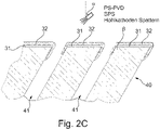
- FIG. 2A to 2C An embodiment of a method for coating a substrate 40 with an internal cavity structure 41 is shown schematically.
- FIG. 2A a starting situation, ie a substrate 40 having an internal cavity structure 41 .
- the representation according to Figure 2A is simplified for the sake of simplicity in several respects.
- the substrate 40 is shown as a cube for the sake of simplicity, although in principle other substrate shapes, in particular complex shapes, which are adapted to the structural conditions in the aircraft engine 10, for example, can also be used.
- the illustrated substrate 40 according to FIG Figure 2A can also be understood as a section from a larger part.
- the cavity structure 41 inside the substrate 40 is in the embodiment according to FIG Figure 2A by three tubular cavities (e.g. as bores inclined to the surface O at an angle ⁇ , see Figure 2B ) with openings 42 in two surfaces O of the substrate 40 symbolized.
- the cavity structure 41 it is also possible for a large number of bores to be used as the cavity structure 41 .
- the holes do not all have to run in one direction.
- a complex, amorphous or honeycomb structure inside the substrate 40 is used as the cavity structure 41 .
- the mean diameters of the voids (in 1 of the tubular cavities) in the range of 0.5 to 1.5 mm.
- the cavity structure 41 can, for example, be part of a cooling system through which a coolant can flow.
- turbine blades can be equipped with an internal cooling system.
- the substrate 40 can be produced by an additive manufacturing method (ALM: Additive Layer Manufacturing) or by a casting method.
- ALM additive Manufacturing
- the cavity structure 41 can be constructed, for example, by laser drilling or with ALM.
- the substrate 40 is built up layer by layer from a nickel alloy (examples are given below) by laser sintering or laser melting. Typical parameters are temperatures between 900 and 1000 °C, pressures between 100 and 110 MPa and times up to 2 hours. If deemed necessary, the substrate 40 may be polished or ground prior to coating.
- the substrate 40 can also be produced by a blown powder ALM method or a cold spray method.
- the substrate 40 already has an internal cavity structure 41 before the subsequent coatings.
- the substrate 40 is metallic and is produced at least partially by a layer application method or by a casting method.
- the substrate 40 can have a proportion of a high-temperature nickel alloy, in particular CMSX4, CMSX3, C 263, Mar M 002 or C 1023, or consist of such a material.
- a diffusion layer 31 is applied to the substrate 40, which is shown in the sectional view of FIG Figure 2B is shown.
- an aluminide layer is applied as a diffusion layer 31 by a pack aluminizing known per se, since this method is economically advantageous.
- the substrate 41 is heated cyclically at temperatures between 800 and 1000° C. together with an aluminum-containing powder.
- the pack aluminizing typically takes several hours, followed by a thermal post-treatment so that diffusion into the substrate 41 can take place.
- a single diffusion layer 31 is applied, which in principle can also have a layer sequence.
- a possible embodiment of the diffusion layer 31 can have a proportion of an X aluminide with X selected from aluminum, chromium, platinum and/or nickel, or consist of these substances.
- X selected from aluminum, chromium, platinum and/or nickel, or consist of these substances.
- a pure aluminide layer or a layer with two or more components can also be applied.
- the at least one diffusion layer 31 can also have a proportion of MCrAlY with M selected from nickel, cobalt, iron and Y selected from yttrium, ytterbium, lanthanum or a rare earth, or consist of this substance.
- Such a layer can be applied by means of an ALM method (blown powder) or a PVD method.
- the diffusion layer 31 (e.g. with a thickness of 10 to 90 ⁇ m) allows sufficient adhesion promotion, offers protection against oxidation and provides sufficiently prepared surfaces for a subsequent coating with a thermal protective layer 32.
- a thermal protective layer 32 is applied to the at least one diffusion layer 31 using a plasma spray PVD (PS-PVD) method or a suspension plasma spray (SPS) method (spray angle a). This is in Figure 2C shown.
- PS-PVD plasma spray PVD
- SPS suspension plasma spray
- both methods do not clog the openings 42 of the cavity structure 41 or only do so to a small extent, so that, for example, after the coating, the openings 42 do not have to be reworked by means of laser drilling.
- the coating is created from a gas flow (see 3 ) which may be inclined or parallel to the surface O of the substrate 40 (see FIG Figures 3A, 3B ). This can reduce or prevent the deposition of coating material in openings 42 .
- a typical thermal protective layer 32 is composed of one to three individual layers approximately 0.1 mm to 0.3 mm thick.
- the thermal protection layer 32 reflects incident hot gas radiation, forms a thermal insulation layer between the hot gas and the substrate 40 and forms a protective layer against hot gas corrosion (sulfidation).
- the total thickness of the thermal protective layer 32 is 0.4 to 0.5 mm and means a temperature relief of between 40 and 70 K for the underlying metal of the substrate 40.
- FIG. 3A a substrate 40 is shown onto which, as in connection with FIG Figure 2B described, a diffusion layer 31 was applied.
- a gas flow G e.g. the carrier gas flow
- the main flow direction H not perpendicular to the substrate surface O but at an angle
- clogging of the openings 42 of the cavity structure 41 is minimized or prevented.
- a maximum of 30% blockage of the openings 42 could be acceptable in one embodiment.
- the gas stream G thus has a flow component X parallel to the surface O of the substrate 40 in any case. It is also possible to choose the angle ⁇ smaller than 30° or smaller than 15°.
Landscapes
- Chemical & Material Sciences (AREA)
- Engineering & Computer Science (AREA)
- Mechanical Engineering (AREA)
- Materials Engineering (AREA)
- Metallurgy (AREA)
- Chemical Kinetics & Catalysis (AREA)
- Organic Chemistry (AREA)
- Physics & Mathematics (AREA)
- Plasma & Fusion (AREA)
- Inorganic Chemistry (AREA)
- General Engineering & Computer Science (AREA)
- Combustion & Propulsion (AREA)
- Ceramic Engineering (AREA)
- Turbine Rotor Nozzle Sealing (AREA)
Description
- Die Erfindung betrifft ein Verfahren zur Beschichtung eines Substrates mit einer Hohlraumstruktur mit den Merkmalen des Anspruchs 1.
- In vielen Bereichen der Technik, wie z.B. im Bereich von Flugzeugtriebwerken, werden Bauteile durch hohe Temperaturen beansprucht. In den meisten Fällen sind diese Bauteile heißen Gasen, wie z.B. Verbrennungsgasen in Ofen-Feuerungen oder in Brennkammern von Flugzeugtriebwerken, ausgesetzt. Daher ist die thermische Widerstandsfähigkeit solcher Bauteile von Bedeutung.
- Ein Mittel zur Erhöhung der thermischen Widerstandsfähigkeit ist eine Beschichtung eines Substrates für ein Bauteil mit einer thermischen Schutzschicht (TBC Thermal Barrier Coating). Verfahren zur Beschichtung mit einer thermischen Schutzschicht sind z.B. aus folgenden Veröffentlichungen bekannt:
-
EP 3 150 741 A1 , - Goral et al., The technology of Plasma Spray Physical Vapour Deposition, Journal of Achievements in Materials and Manufacturing Engineering Vol. 55, No. 2, S. 689 ff,
- Goral et al., The PS-PVD method - formation of columnar TBCs on CMSX-4 superalloy, Journal of Achievements in Materials and Manufacturing Engineering Vol. 55, No. 2, S. 907 ff;
- Mauer et al. Novel opportunities for thermal spray by PS-PVD, Surface & Coating Technology, Vol. 269 (2015), S. 53 ff,
- Mauer et al., Process diagnostic in suspension plasma spraying, Surface & Coating Technology, Vol. 205 (2010), S. 961 ff,
-
DE 10 2005 060243 A1 , -
US 2011/159260 A1 . - Metallische Substrate, aus denen solche Bauteile aufgebaut werden, weisen u.U. Hohlraumstrukturen, wie z.B. Kühlkanäle, auf, wobei die internen Hohlraumstrukturen in Öffnungen an der Oberfläche der Substrate münden. Die Hohlraumstrukturen können beim Herstellungsprozess (z.B. durch ein additives Schichtaufbringungsverfahren; ALM (Additive Layer Manufacturing)) im Substrat aufgebaut werden oder die Hohlraumstrukturen werden nach der Herstellung des Substrates z.B. durch Laserbohren in ein gegossenes Substrat eingebracht.
- Es besteht die Aufgabe, effiziente Verfahren zur Beschichtung von Substraten mit einer bereits vorhandenen, internen Hohlraumstruktur der beschriebenen Art zu schaffen.
- Die Aufgabe wird durch ein Verfahren mit den Merkmalen des Anspruchs 1 gelöst.
- Dabei wird ein Substrat mit einer internen Hohlraumstruktur, insbesondere einer Kühlstruktur, beschichtet. Die Hohlraumstruktur weist dabei Öffnungen in der Oberfläche des Substrats auf.
- In einem ersten Schritt wird mindestens eine haftvermittelnde Schicht auf das Substrat aufgebracht. Dabei kann eine Diffusionsschicht (d.h. eingebracht durch ein Diffusionsverfahren) auf das Substrat aufgebracht werden oder eine andere metallische Schicht.
- Die Diffusionsschicht dient u.a. der Haftvermittlung für die nachfolgend aufgebachte, mindestens eine thermische Schutzschicht.
- Die mindestens eine thermische Schutzschicht wird unter Verwendung eines Suspension Plasma Spray (SPS) Verfahrens auf die mindestens eine Diffusionsschicht aufgebracht.
- Dieses Verfahren ist gut dafür geeignet, die Öffnungen der bereits vorhandenen internen Hohlraumstruktur bei der Beschichtung nicht oder nur wenig zu blockieren. Dies liegt u.a. daran, dass die feinen Teilchen in dem vorhandenen Gasströmen der Verfahren so klein sind, dass sie vom Gasstrom mitgeführt werden. Das Freihalten der Öffnungen erspart aufwändige Nacharbeiten, wie z.B. das nachträgliche Aufbohren mit einem Laserbohrverfahren.
- Das SPS Verfahren weist einen Gasstrom mit einer Strömungskomponente parallel zur Oberfläche des Substrates auf, d.h. die Hauptströmungsrichtung des Gasstroms ist nicht senkrecht auf das Substrat gerichtet. Dabei weist die Hauptströmungsrichtung des Gasstroms einen Winkel α zur Oberfläche des Substrats auf, der kleiner als 30° ist, insbesondere kleiner als 15° ist. Alternativ liegt die Hauptströmungsrichtung des Gasstroms parallel zur Oberfläche des Substrats. Bei einem flachen Auftreffwinkel oder gar einer parallelen, zum Substrat orientierten Hauptströmungsrichtung wird eine mögliche Blockade der Öffnungen der Hohlraumstrukturen minimiert.
- In einer weiteren Ausführungsform ist der Gasstrom ein Prozessgasstrom und / oder Trägergasstrom des SPS Verfahrens. Damit erfolgt eine Interaktion zwischen dem Gasstrom und dem Substrat, indem ein direktes Abscheiden aus dem Gasstrom auf die Oberfläche des Substrats erfolgt. Dies reduziert die Abscheidung in Vertiefungen in der Oberfläche.
- Dabei ist es insbesondere möglich, dass der Teilen beladene Gasstrom durch eine Stokes Zahl St < 1, insbesondere von St < 0.1, ganz insbesondere von St < 0,01, ganz insbesondere St < 0.001 charakterisiert wird. Die dimensionslose Stokes-Zahl St ist ein Maß für die Massenträgheit eines Teilchens für seine Bewegung in einem bewegten Fluid, hier einem Gas. Sie ist das Verhältnis der charakteristischen Zeit tT, mit der sich durch Reibung die Geschwindigkeit des Teilchens der Geschwindigkeit des umgebenden Gases anpasst, zur charakteristischen Zeit tP , in der das Gas selbst durch äußere Einflüsse seine Geschwindigkeit ändert.
- In einer Ausführungsform wird die mindestens eine Diffusionsschicht durch ein Pack Aluminizing, ein PVD- Verfahren oder ein additives Schichtenverfahren aufgebracht. Alle diese Verfahren erlauben das effiziente Aufbringen der dünnen Diffusionsschicht.
- Diese kann in einer Ausführungsform einen Anteil an MCrAIY mit
- M ausgewählt aus Nickel, Kobalt, Eisen und
- Y ausgewählt aus Yttrium, Ytterbium, Lanthan oder einer Seltenen Erde
- Es ist auch möglich, dass die mindestens eine Diffusionsschicht einen Anteil an einem X-Aluminid mit
X ausgewählt aus Chrom, Platin und / oder Nickel oder Aluminium und Chrom, Platin und / oder Nickel aufweist oder aus diesem Substanzen besteht. - In einer Ausführungsform weist die mindestens eine thermische Schutzschicht einen Anteil aus Yttrium (z.B. in Form von Y2O3) und / oder stabilisiertem Zirkoniumoxid (ZrO2) auf oder besteht aus dieser Substanz.
- In einer weiteren Ausführungsform ist das Substrat metallisch und mindestens teilweise durch ein additives Schichtaufbringungsverfahren (ALM) oder durch ein Gussverfahren hergestellt. Diese Verfahren erlauben die Herstellung komplex geformter Bauteile, wie z.B. Turbinenschaufeln.
- Da die Bauteile im Betrieb thermisch hoch belastet werden, weist das Substrat einen Anteil einer Hochtemperatur-Nickellegierung, insbesondere CMSX4, CMSX3, C 263, Mar M 002 und / oder C 1023 auf oder besteht aus einem solchen Material.
- Ferner können Kanäle der Hohlraumstruktur und / oder die Öffnungen der Hohlraumstruktur einen mittleren Durchmesser zwischen 0,5 bis 1,5 mm, insbesondere 1 mm aufweisen. Diese Dimensionen erlauben die effiziente Verwendung der Hohlraumstruktur für Kühlzwecke.
- Mit mindestens einer der Ausführungsformen für ein Verfahren zur Beschichtung ist ein Substrat mit einer Hohlraumstruktur im Inneren des Substrats herstellbar, wobei die Hohlraumstruktur Öffnungen in der Oberfläche des Substrats aufweist.
- Ein dermaßen hergestelltes Substrat kann z.B. in einer Brennkammerschindel einer Brennkammer eines Flugzeugtriebwerkes, in einer Turbinenschaufel eines Flugzeugtriebwerkes oder in einem Liner einer Turbine in einem Flugzeugtriebwerk verwendet werden.
- In Zusammenhang mit den in den Figuren dargestellten Ausführungsbeispielen wird die Erfindung erläutert. Dabei zeigt
- Fig. 1
- eine schematische Teilschnittansicht eines Flugzeugtriebwerkes;
- Fig. 2A
- eine schematische perspektivische Ansicht einer Ausführungsform eines Substrates mit einer internen Hohlraumstruktur;
- Fig. 2B
- eine Schnittansicht des Substrats gemäß
Fig. 2A , versehen mit einer Diffusionsschicht; - Fig. 2C
- eine Schnittansicht des beschichteten Substrats gemäß
Fig. 2B , versehen mit einer thermischen Schutzschicht; - Fig. 3A
- eine Schnittansicht einer weiteren Ausführungsform eines Substrates mit einer Diffusionsschicht, die mittels eines SPS Verfahrens mit einer thermischen Schutzschicht beschichtet wird, wobei ein Gasstrom unter einem Winkel zur Oberfläche des Substrates geführt wird;
- Fig. 3B
- eine Schnittansicht einer Ausführungsform eines Substrates mit einer Diffusionsschicht, die mittels eines SPS Verfahrens mit einer thermischen Schutzschicht beschichtet wird, wobei ein Gasstrom parallel zur Oberfläche des Substrates geführt wird.
- Das Flugzeugtriebwerk 10 gemäß
Fig. 1 zeigt ein grundsätzlich bekanntes Beispiel einer Turbomaschine. Diese ist lediglich ein Beispiel für eine Vorrichtung, in der Substrate 40 mit einer internen Hohlraumstruktur 41 (sieheFig. 2 ) für thermisch belastete Bauteile verwendet werden. Grundsätzlich ist es auch möglich, solche Substrate 40 auch in anderen Vorrichtungen, wie z.B. Ofen-Feuerungen, zu verwenden. - Das Flugzeugtriebwerk 10 ist in an sich bekannter Weise meistens als Mehr-Wellen-Triebwerk ausgebildet und umfasst in Strömungsrichtung hintereinander einen Lufteinlass 11, einen in einem Fangehäuse 24 umlaufenden Fan 12 (entsprechend einem Niederdruckkompressor), einen Mitteldruckkompressor 13, einen Hochdruckkompressor 14, eine Brennkammer 15, eine Hochdruckturbine 16, eine Mitteldruckturbine 17 und eine Niederdruckturbine 18, sowie eine Abgasdüse 19, die sämtlich um eine zentrale Triebwerksachse 1 angeordnet sind.
- Die Hochdruckturbine 16 ist dazu ausgebildet, den Hochdruckkompressor 14 über eine Hochdruckwelle 20 anzutreiben. Die Mitteldruckturbine 17 ist dazu ausgebildet, den Mitteldruckkompressor 13 über eine Mitteldruckwelle 21 anzutreiben. Die Niederdruckturbine 18 ist dazu ausgebildet, den Fan 12 über eine Niederdruckwelle 22 anzutreiben.
- Alternative Ausführungsformen eines Flugzeugtriebwerks 10 können auch zwei Wellen statt drei Wellen aufweisen.
- In einer hier nicht dargestellten Ausführungsform ist die Antriebswelle des Fans 12 mit einem Untersetzungsgetriebe gekoppelt, so dass der Fan 12 mit einer niedrigeren Drehzahl als die antreibende Turbine betrieben werden kann. Auch in solchen Getriebe-Fan Triebwerken werden thermisch belastete Bauteile mit Subtraten 40 mit internen Hohlraumstrukturen 41 verwendet.
- Bei der Ausführungsform, die in
Fig. 1 dargestellt ist, strömt ein erster Teil des Luftstroms, der durch das Flugzeugtriebwerk 10 geht, durch den Mitteldruckkompressor 13 und den Hochdruckkompressor 14, wobei der Druck des Luftstroms erhöht wird. Dieser Luftstrom wird dann der Brennkammer 15 zugeführt und mit eingedüstem Brennstoff verbrannt. Die bei der Verbrennung entstehenden heißen Gase strömen durch die Hochdruckturbine 16, die Mitteldruckturbine 17 und die Niederdruckturbine 18 und treiben sie dadurch an. Schließlich strömen die heißen Gase aus der Abgasdüse 19 aus und erzeugen somit einen Teil des Schubs des Flugzeugtriebwerks 10. - Ein zweiter Teil des Luftstroms wird um den Hauptteil des Flugzeugtriebwerks herumgeführt und strömt durch einen Nebenstromkanal 23, der durch ein Fangehäuse 24 definiert wird. Dieser zweite Teil der Luft verlässt das Flugzeugtriebwerk 10 durch eine Fandüse 25 und erzeugt dabei einen größeren Teil des Schubs - verglichen mit dem austretenden Gas aus der Abgasdüse 19 - des Flugzeugtriebwerks 10.
- In
Fig. 2A bis 2C ist eine Ausführungsform eines Verfahrens zur Beschichtung eines Substrates 40 mit einer internen Hohlraumstruktur 41 schematisch dargestellt. - Dabei zeigt
Fig. 2A eine Ausgangssituation, d.h. ein Substrat 40, das eine interne Hohlraumstruktur 41 aufweist. Die Darstellung gemäßFig. 2A ist aus Gründen der Einfachheit in mehrfacher Hinsicht vereinfachend dargestellt. So ist das Substrat 40 vereinfachend als Würfel dargestellt, wobei grundsätzlich auch andere Substratformen, insbesondere komplexe Formen, die z.B. an die baulichen Gegebenheiten in dem Flugzeugtriebwerk 10 angepasst sind, verwendbar sind. Das dargestellte Substrat 40 gemäßFig. 2A kann auch als Ausschnitt aus einem größeren Teil aufgefasst werden. - Die Hohlraumstruktur 41 im Inneren des Substrates 40 wird in der Ausführungsform gemäß
Fig. 2A durch drei röhrenförmige Hohlräume (z.B. als zur Oberfläche O unter einem Winkel β geneigte Bohrungen, sieheFig. 2B ) mit Öffnungen 42 in zwei Oberflächen O des Substrates 40 symbolisiert. Grundsätzlich ist es auch möglich, dass eine Vielzahl von Bohrungen als Hohlraumstruktur 41 verwendet wird. Auch müssen die Bohrungen nicht alle in eine Richtung verlaufen. Es ist auch möglich, dass eine komplexe, amorphe oder Wabenstruktur im Inneren des Substrates 40 als Hohlraumstruktur 41 verwendet wird. Typischerweise liegen die mittleren Durchmesser der Hohlräume (inFig. 1 der röhrenförmigen Hohlräume) im Bereich von 0,5 bis 1,5 mm. Die Hohlraumstruktur 41 kann z.B. Teil eines Kühlsystems sein, dass von einem Kühlmittel durchströmbar ist. So können Turbinenschaufeln mit einem inneren Kühlsystem ausgestattet sein. - Das Substrat 40 kann durch ein additives Herstellungsverfahren (ALM: Additive Layer Manufacturing) oder durch ein Gussverfahren hergestellt werden. Die Hohlraumstruktur 41 kann z.B. durch Laserbohrungen oder beim ALM aufgebaut werden.
- Bei einer ALM Herstellung aus einem Pulverbett wird das Substrat 40 Schicht für Schicht aus einer Nickel-Legierung (Beispiele werden unten angegeben) durch Lasersinterung oder Laserschmelzen aufgebaut. Typische Parameter sind dabei Temperaturen zwischen 900 und 1000 °C, Drücke zwischen 100 und 110 MPa und Zeiten bis zu 2 Stunden. Wenn es erforderlich erscheint, kann das Substrat 40 vor einer Beschichtung poliert oder geschliffen werden.
- Das Substrat 40 kann aber auch durch ein Blown Powder ALM Verfahren oder ein Cold Spray Verfahren hergestellt werden.
- In jedem Fall weist das Substrat 40 bereits vor den nachfolgenden Beschichtungen eine interne Hohlraumstruktur 41 auf.
- Das Substrat 40 ist in der dargestellten Ausführungsform metallisch und ist mindestens teilweise durch ein Schichtaufbringungsverfahren oder durch ein Gussverfahren hergestellt. Dabei kann das Substrat 40 einen Anteil einer Hochtemperatur-Nickellegierung, insbesondere CMSX4, CMSX3, C 263, Mar M 002 oder C 1023 aufweisen oder aus einer solchem Material bestehen.
- Eine typische Zusammensetzung für CMSX4 der Firma Cannon-Muskegon ist (außer Nickel):
- 6,5 Gew.-% Cr,
- 9,6 Gew.-% Co,
- 0,6 Gew.-% Mo,
- 6,4 Gew.-% W,
- 5,6 Gew.-% Al,
- 1,0 Gew.-% Ti,
- 6,5 Gew.-% Ta.
- 3,0 Gew.-% Re,
- 0,1 Gew.-% Hf.
- Eine typische Zusammensetzung für CMSX3 der Firma Cannon-Musgekon ist (außer Nickel):
- 8,0 Gew.-% Cr,
- 4,8 Gew.-% Co,
- 0,6 Gew.-% Mo,
- 8,0 Gew.-% W,
- 5,6 Gew.-% Al,
- 1,0 Gew.-% Ti,
- 6,3 Gew.-% Ta,
- 0,1 Gew.-% Hf.
- Eine typische Zusammensetzung für C 263 (außer Nickel):
- 16 Gew.-% Cr,
- 15 Gew.-% Co,
- 3 Gew.-% Mo,
- 1,25 Gew.-% W,
- 2,5 Gew.-% Al,
- 5,0 Gew.-% Ti,
- 0,025 Gew.-% C,
- 0,018 Gew.-% B,
- Eine typische Zusammensetzung für Mar M 002 der Firma Cannon-Muskegon ist (außer Nickel):
- 8,0 Gew-% Cr,
- 10 Gew-% Co,
- 10 Gew-% W,
- 5,5 Gew-% Al,
- 1,5 Gew-% Ti,
- 2,6 Gew-% Ta,
- 1,5 Gew.-% Hf,
- 0,15 Gew.% C,
- 0,015 Gew-% B,
- 0,03 Gew.-% Zr.
- Eine typische Zusammensetzung für C 1023 ist (außer Nickel):
- 4,2 Gew.-% Al,
- 0,16 Gew.-% C,
- 10 Gew.-% Co,
- 15,5 Gew.-% Cr,
- 8,5 Gew.-% Mo,
- 3,6 Gew.-% Ti,
- 0,006 Gew.-% B.
- Es sei angemerkt, dass diese Zusammensetzungen hier ohne Toleranzangaben angegeben sind, die dem Fachmann grundsätzlich bekannt sind.
- In einem ersten Schritt wird eine Diffusionsschicht 31 auf das Substrat 40 aufgebracht, was in der Schnittansicht der
Fig. 2B dargestellt ist. - In der dargestellten Ausführungsform erfolgt das Aufbringen einer Aluminid-Schicht als Diffusionsschicht 31 durch ein an sich bekanntes Pack Aluminizing, da diese Methode wirtschaftlich vorteilhaft ist.
- Dafür wird das Substrat 41 zusammen mit einem aluminium-haltigen Pulver zyklisch bei Temperaturen zwischen 800 und 1000°C erhitzt. Das PackAluminizing dauert typischerweise mehrere Stunden, wobei anschließend eine thermische Nachbehandlung erfolgt, damit eine Diffusion in das Substrat 41 erfolgen kann.
- In der dargestellten Ausführungsform wird eine einzige Diffusionsschicht 31 aufgetragen, wobei diese grundsätzlich auch eine Schichtenfolge aufweisen kann.
- Eine mögliche Ausführungsform der Diffusionsschicht 31 kann einen Anteil an einem X-Aluminid mit X, ausgewählt aus Aluminium, Chrom, Platin und / oder Nickel, aufweisen oder aus diesen Substanzen bestehen. Somit kann insbesondere auch eine reine Aluminid-Schicht oder eine Schicht mit zwei oder mehr Komponenten aufgebracht werden.
- Auch kann die mindestens eine Diffusionsschicht 31 einen Anteil an MCrAIY mit M, ausgewählt aus Nickel, Kobalt, Eisen und Y ausgewählt aus Yttrium, Ytterbium, Lanthan oder einer Seltenen Erde, aufweisen oder aus dieser Substanz bestehen.
- Eine solche Schicht kann mittels eines ALM Verfahrens (Blown Powder) oder einem PVD Verfahren aufgebracht werden.
- Die Diffusionsschicht 31 (z.B. mit einer Dicke von 10 bis 90 µm) erlaubt eine ausreichende Haftvermittlung, bietet einen Oxidationsschutz und stellt ausreichend vorbereitete Oberflächen für eine nachfolgende Beschichtung mit einer thermischen Schutzschicht 32 zur Verfügung.
- Nach dem Aufbringen der Diffusionsschicht 31 wird eine thermische Schutzschicht 32 unter Verwendung eines Plasma-Spray PVD (PS-PVD) Verfahrens oder eines Suspension Plasma Spray (SPS) Verfahrens (Spritzwinkel a) auf die mindestens eine Diffusionsschicht 31 aufgebracht. Dies ist in
Fig. 2C dargestellt. - Dabei ist erkennbar, dass die Verblockung der Öffnungen O verhältnismäßig klein ist.
- Beide Verfahren setzen beim Abscheiden der thermischen Schutzschicht 32 die Öffnungen 42 der Hohlraumstruktur 41 nicht oder nur in geringem Maße zu, so dass z.B. nach dem Beschichten keine Nachbearbeitung der Öffnungen 42 mittels Laserbohren notwendig ist. Eine Nachbehandlung der Öffnungen 42, insbesondere mit einem Laser, führt zu einer thermische Belastung und damit Schwächung der thermischen Schutzschicht 32 bei der Herstellung.
- Beim PS-PVD wird der größte Teil des injizierten Pulvers in die Gasphase umgewandelt, was bewirkt, dass sich die Öffnungen 42 im Substrat weniger zusetzen.
- Bei dem SPS Verfahren wird die Beschichtung aus einem Gasfluss (siehe
Fig. 3 ) abgeschieden, der gegenüber der Oberfläche O des Substrats 40 geneigt oder parallel ausgerichtet sein kann (sieheFig. 3A, 3B ). Dies kann die Abscheidung von Beschichtungsmaterial in Öffnungen 42 reduzieren beziehungsweise verhindern. - Eine typische thermische Schutzschicht 32 setzt sich aus ein bis drei in etwa 0.1 mm bis 0.3 mm dicken Einzelschichten zusammen.
- Die thermische Schutzschicht 32 reflektiert einfallende Heißgasstrahlung, bildet eine thermische Isolationsschicht zwischen dem Heißgas und dem Substrat 40 und bildet eine Schutzschicht gegen Heißgaskorrosion (Sulfidation). Die Gesamtdicke der thermischen Schutzschicht 32 erreicht 0,4 bis 0,5 mm und bedeutet für das darunter liegende Metall des Substrates 40 eine Temperaturentlastung zwischen 40 und 70 K.
- Im Folgenden werden Ausführungsformen für die Abscheidung der thermischen Schutzschicht 32 mittels eines SPS Verfahrens beschrieben.
- In
Fig. 3A ist ein Substrat 40 dargestellt, auf das, wie im Zusammenhang mitFig. 2B beschrieben, eine Diffusionsschicht 31 aufgebracht wurde. - Wenn ein Gasstrom G (z.B. der Trägergasstrom) des SPS Verfahrens mit der Hauptströmungsrichtung H nicht senkrecht zur Substratoberfläche O, sondern unter einem Winkel verwendet wird, wird das Zusetzen der Öffnungen 42 der Hohlraumstruktur 41 minimiert oder verhindert. Eine Verblockung der Öffnungen 42 von maximal 30% könnte in einer Ausführungsform akzeptiert werden.
- In
Fig. 3A ist dargestellt, dass die Hauptströmungsrichtung H des Gasstroms G unter einem Winkel von γ=30° auf die Oberfläche O des Substrats 40 trifft. Es sei angemerkt, dass die Hauptströmungsrichtung H des Gasstroms G nicht gleich dem Spritzwinkel α sein muss. - Damit weist der Gasstrom G in jedem Fall eine Strömungskomponente X parallel zur Oberfläche O des Substrates 40 auf. Es ist auch möglich, den Winkel α kleiner als 30° oder auch kleiner als 15° zu wählen.
- Bei einem SPS Verfahren ist eine Beschichtung aus der Gasphase möglich, da die feinen Tropfen in der Suspension (z.B. Ethanol, Wasser) dem Gasstrom G folgen und sich direkt aus dem Gasstrom G abscheiden. Daher kann der Gasstrom G sogar parallel zur Oberfläche O des Substrats 40 ausgerichtet sein, wie dies in der
Fig. 3B dargestellt ist. Bei dieser Ausführungsform ist das Risiko der Verblockung der Öffnungen 42 am geringsten. -
- 1
- Triebwerksachse
- 10
- Flugzeugtriebwerk
- 11
- Lufteinlass
- 12
- Fan
- 13
- Mitteldruckkompressor
- 14
- Hochdruckkompressor
- 15
- Brennkammer
- 16
- Hochdruckturbine
- 17
- Mitteldruckturbine
- 18
- Niederdruckturbine
- 19
- Abgasdüse
- 20
- Hochdruckwelle
- 21
- Mitteldruckwelle
- 22
- Niederdruckwelle
- 23
- Nebenstromkanal
- 24
- Fangehäuse
- 25
- Fandüse
- 31
- Diffusionsschicht
- 32
- thermische Schutzschicht
- 40
- Substrat
- 41
- Hohlraumstruktur
- 42
- Öffnung
- G
- Gasfluss
- O
- Oberfläche
- X
- Koordinatenrichtung parallel zur Oberfläche
- α
- Spritzwinkel
- β
- Neigung Hohlraumstruktur gegenüber Oberfläche
- γ
- Winkel Gasfluss gegenüber Oberfläche
Claims (12)
- Verfahren zur Beschichtung eines Substrates (40) mit einer Hohlraumstruktur (41), insbesondere einer Kühlstruktur, im Inneren des Substrats (40), wobei die Hohlraumstruktur (41) Öffnungen (42) in der Oberfläche (O) des Substrats (40) aufweist, wobeia) mindestens eine haftvermittelnde Schicht, insbesondere eine Diffusionsschicht (31) oder mindestens eine andere metallische Schicht auf das Substrat (40), insbesondere auf die Oberfläche (O) des Substrates (40), aufgebracht wird und anschließendb) mindestens eine thermische Schutzschicht (32) unter Verwendung eines Suspension Plasma Spray (SPS) Verfahrens auf die mindestens eine Diffusionsschicht (31) aufgebracht wird,dadurch gekennzeichnet, dass
die Hauptströmungsrichtung (H) des Gasstroms (G) parallel zur Oberfläche (O) des Substrats (40) liegt oder die Hauptströmungsrichtung (H) des Gasstroms (G) einen Winkel α zur Oberfläche (O) des Substrats (40) aufweist, der kleiner als 30° ist. - Verfahren nach Anspruch 1, dadurch gekennzeichnet, dass die Hauptströmungsrichtung (H) des Gasstroms (G) einen Winkel α zur Oberfläche (O) des Substrats (40) aufweist, der kleiner als 15° ist
- Verfahren nach mindestens einem der Ansprüche 1 oder 2, dadurch gekennzeichnet, dass der Gasstrom (G) ein Prozessgasstrom und / oder ein Trägergasstrom ist.
- Verfahren nach mindestens einem der vorhergehenden Ansprüche, dadurch gekennzeichnet, dass der Teilchen beladene Gasstrom (G) eine Stokes Zahl von weniger als 1, insbesondere von weniger als 0.1, ganz insbesondere von weniger als 0.01, ganz insbesondere von weniger als 0.001 aufweist.
- Verfahren nach mindestens einem der vorhergehenden Ansprüche, dadurch gekennzeichnet, dass die mindestens eine Diffusionsschicht (31) durch ein Pack Aluminizing, ein PVD- Verfahren oder ein additives Schichtenverfahren aufgebracht wird.
- Verfahren nach mindestens einem der vorhergehenden Ansprüche, dadurch gekennzeichnet, dass die mindestens eine Diffusionsschicht (31) einen Anteil an MCrAIY, mitM, ausgewählt aus Nickel, Kobalt, Eisen undY, ausgewählt aus Yttrium, Ytterbium, Lanthan oder einer Seltenen Erdeaufweist oder aus dieser Substanz besteht.
- Verfahren nach mindestens einem der vorhergehenden Ansprüche, dadurch gekennzeichnet, dass die mindestens eine Diffusionsschicht (31) einen Anteil an einem X-Aluminid mit
X, ausgewählt aus Chrom, Platin und / oder Nickel oder Aluminium und Chrom, Platin und / oder Nickel aufweist oder aus diesen Substanzen besteht. - Verfahren nach mindestens einem der vorhergehenden Ansprüchen, dadurch gekennzeichnet, dass die mindestens eine metallische Schicht unter Verwendung eines Plasma-Spray PVD (PS-PVD) Verfahrens, eines Hohlkathoden-Sputter Verfahrens oder eines Suspension Plasma Spray (SPS) Verfahrens auf die mindestens eine Diffusionsschicht (31) aufgebracht wird.
- Verfahren nach mindestens einem der vorhergehenden Ansprüche, dadurch gekennzeichnet, dass die mindestens eine thermische Schutzschicht (32) einen Anteil aus Yttrium und / oder stabilisiertem Zirkoniumoxid aufweist oder aus der Substanz besteht.
- Verfahren nach mindestens einem der vorhergehenden Ansprüche, dadurch gekennzeichnet, dass das Substrat (40) metallisch ist und mindestens teilweise durch ein Schichtaufbringungsverfahren oder durch ein Gussverfahren hergestellt ist.
- Verfahren nach mindestens einem der vorhergehenden Ansprüche, dadurch gekennzeichnet, dass das Substrat (40) einen Anteil einer Hochtemperatur-Nickellegierung, insbesondere CMSX4, CMSX3, C 263, Mar M 002 und / oder C 1023 aufweist oder aus einem solchem Material besteht.
- Verfahren nach mindestens einem der vorhergehenden Ansprüche, dadurch gekennzeichnet, dass Kanäle der Hohlraumstruktur (41) und / oder die Öffnungen (42) der Hohlraumstruktur (41) einen mittleren Durchmesser zwischen 0,5 bis 1,5 mm, insbesondere 1 mm, aufweisen.
Applications Claiming Priority (1)
| Application Number | Priority Date | Filing Date | Title |
|---|---|---|---|
| DE102018112353.1A DE102018112353A1 (de) | 2018-05-23 | 2018-05-23 | Verfahren zur Beschichtung eines Substrates mit einer Hohlraumstruktur |
Publications (2)
| Publication Number | Publication Date |
|---|---|
| EP3572551A1 EP3572551A1 (de) | 2019-11-27 |
| EP3572551B1 true EP3572551B1 (de) | 2022-06-29 |
Family
ID=66589217
Family Applications (1)
| Application Number | Title | Priority Date | Filing Date |
|---|---|---|---|
| EP19174701.3A Active EP3572551B1 (de) | 2018-05-23 | 2019-05-15 | Verfahren zur beschichtung eines substrates mit einer hohlraumstruktur |
Country Status (3)
| Country | Link |
|---|---|
| US (1) | US20190360107A1 (de) |
| EP (1) | EP3572551B1 (de) |
| DE (1) | DE102018112353A1 (de) |
Families Citing this family (3)
| Publication number | Priority date | Publication date | Assignee | Title |
|---|---|---|---|---|
| US11585224B2 (en) * | 2020-08-07 | 2023-02-21 | General Electric Company | Gas turbine engines and methods associated therewith |
| CN112853254B (zh) * | 2020-12-31 | 2022-06-14 | 广东省科学院新材料研究所 | 一种非晶柱状结构涂层及其制备方法和应用 |
| CN114015980B (zh) * | 2022-01-10 | 2022-04-01 | 北京航空航天大学 | 发动机涡轮叶片表面制备热障涂层的方法 |
Family Cites Families (6)
| Publication number | Priority date | Publication date | Assignee | Title |
|---|---|---|---|---|
| KR101097927B1 (ko) * | 2005-08-18 | 2011-12-23 | 재단법인서울대학교산학협력재단 | 액정 표시장치 제조 방법 |
| DE102005060243A1 (de) * | 2005-12-14 | 2007-06-21 | Man Turbo Ag | Verfahren zum Beschichten einer Schaufel und Schaufel einer Gasturbine |
| EP2354275A1 (de) * | 2009-12-29 | 2011-08-10 | Siemens Aktiengesellschaft | Mehrfachschichtsystem aus metallischer Schicht und keramischer Schicht |
| WO2012059325A2 (de) * | 2010-11-02 | 2012-05-10 | Siemens Aktiengesellschaft | Legierung, schutzschicht und bauteil |
| EP3372707B1 (de) * | 2013-03-15 | 2022-06-29 | Raytheon Technologies Corporation | Spallationsbeständige wärmesperrenbeschichtung |
| GB201517333D0 (en) | 2015-10-01 | 2015-11-18 | Rolls Royce Plc | A method of applying a thermal barrier coating to a metallic article and a thermal barrier coated metallic article |
-
2018
- 2018-05-23 DE DE102018112353.1A patent/DE102018112353A1/de not_active Withdrawn
-
2019
- 2019-05-03 US US16/402,957 patent/US20190360107A1/en not_active Abandoned
- 2019-05-15 EP EP19174701.3A patent/EP3572551B1/de active Active
Also Published As
| Publication number | Publication date |
|---|---|
| US20190360107A1 (en) | 2019-11-28 |
| DE102018112353A1 (de) | 2019-11-28 |
| EP3572551A1 (de) | 2019-11-27 |
Similar Documents
| Publication | Publication Date | Title |
|---|---|---|
| DE69704703T2 (de) | Verbesserte wärmeschutz-beschichtung und verfahren zu ihrer herstellung | |
| EP1673490B1 (de) | Bauteil mit einer schutzschicht zum schutz des bauteils gegen korrosion und oxidation bei hohen temperaturen | |
| EP2436798B1 (de) | Maskierungsmaterial, Maskierungsschicht und Verfahren zum Maskieren eines Substrats | |
| EP2458025B1 (de) | Legierung, Schutzschicht und Bauteil | |
| EP1707650A1 (de) | Matrix und Schichtsystem | |
| EP1974071A1 (de) | Im strömungskanal einer strömungsmaschine anzuordnendes bauteil und spritzverfahren zum erzeugen einer beschichtung | |
| EP1819905A1 (de) | Schichtsystem, verwendung und verfahren zur herstellung eines schichtsystems | |
| EP2392684A1 (de) | Legierung, Schutzchicht und Bauteil | |
| EP3572551A1 (de) | Verfahren zur beschichtung eines substrates mit einer hohlraumstruktur | |
| EP2279282A1 (de) | Verfahren zur herstellung einer optimierten haftvermittlerschicht durch teilweise verdampfung der haftvermittlerschicht und ein schichtsystem | |
| EP1902160B1 (de) | Keramische wärmedämmschicht | |
| EP1692322B1 (de) | Metallische schutzschicht | |
| EP1812613B1 (de) | Bauteil mit Schutzschicht gegen Korrosion und Oxidation bei hohen Temperaturen | |
| EP1834004A1 (de) | Legierung, schutzschicht zum schutz eines bauteils gegen korrosion und oxidation bei hohen temperaturen und bauteil | |
| EP1798299B1 (de) | Legierung, Schutzschicht und Bauteil | |
| EP1900708B1 (de) | Wärmedämmstoff mit hoher zyklischer Temperaturbelastbarkeit | |
| EP1806418A1 (de) | Legierung, Schutzschicht zum Schutz eines Bauteils gegen Korrosion und Oxidation bei hohen Temperaturen und Bauteil | |
| EP1852519B1 (de) | Verfahren zum Herstellen einer Beschichtung | |
| EP1948836A1 (de) | Legierung, schutzschicht zum schutz eines bauteils gegen korrosion und/oder oxidation bei hohen temperaturen und bauteil | |
| EP1707651A1 (de) | Schichtsystem und Verfahren zur Herstellung eines Schichtsystems | |
| EP1806419B1 (de) | Legierung, Schutzschicht zum Schutz eines Bauteils gegen Korrosion und Oxidation bei hohen Temperaturen und Bauteil | |
| EP4155431A1 (de) | Verfahren zur herstellung und entsprechend hergestelltes bauteil aus einer nickelbasissuperlegierung für den heissgaskanal einer strömungsmaschine | |
| EP1783243A1 (de) | Trockene Zusammensetzung, deren Verwendung, Schichtsystem und Verfahren zur Beschichtung | |
| EP2345748A1 (de) | Legierung, Schutzschicht und Bauteil | |
| EP1818419A1 (de) | Legierung, Schutzschicht und Bauteil |
Legal Events
| Date | Code | Title | Description |
|---|---|---|---|
| PUAI | Public reference made under article 153(3) epc to a published international application that has entered the european phase |
Free format text: ORIGINAL CODE: 0009012 |
|
| STAA | Information on the status of an ep patent application or granted ep patent |
Free format text: STATUS: THE APPLICATION HAS BEEN PUBLISHED |
|
| AK | Designated contracting states |
Kind code of ref document: A1 Designated state(s): AL AT BE BG CH CY CZ DE DK EE ES FI FR GB GR HR HU IE IS IT LI LT LU LV MC MK MT NL NO PL PT RO RS SE SI SK SM TR |
|
| AX | Request for extension of the european patent |
Extension state: BA ME |
|
| STAA | Information on the status of an ep patent application or granted ep patent |
Free format text: STATUS: REQUEST FOR EXAMINATION WAS MADE |
|
| 17P | Request for examination filed |
Effective date: 20200527 |
|
| RBV | Designated contracting states (corrected) |
Designated state(s): AL AT BE BG CH CY CZ DE DK EE ES FI FR GB GR HR HU IE IS IT LI LT LU LV MC MK MT NL NO PL PT RO RS SE SI SK SM TR |
|
| RAP3 | Party data changed (applicant data changed or rights of an application transferred) |
Owner name: ROLLS-ROYCE DEUTSCHLAND LTD & CO KG Owner name: FORSCHUNGSZENTRUM JUELICH GMBH |
|
| STAA | Information on the status of an ep patent application or granted ep patent |
Free format text: STATUS: EXAMINATION IS IN PROGRESS |
|
| 17Q | First examination report despatched |
Effective date: 20210806 |
|
| GRAP | Despatch of communication of intention to grant a patent |
Free format text: ORIGINAL CODE: EPIDOSNIGR1 |
|
| STAA | Information on the status of an ep patent application or granted ep patent |
Free format text: STATUS: GRANT OF PATENT IS INTENDED |
|
| INTG | Intention to grant announced |
Effective date: 20220125 |
|
| GRAS | Grant fee paid |
Free format text: ORIGINAL CODE: EPIDOSNIGR3 |
|
| GRAA | (expected) grant |
Free format text: ORIGINAL CODE: 0009210 |
|
| STAA | Information on the status of an ep patent application or granted ep patent |
Free format text: STATUS: THE PATENT HAS BEEN GRANTED |
|
| AK | Designated contracting states |
Kind code of ref document: B1 Designated state(s): AL AT BE BG CH CY CZ DE DK EE ES FI FR GB GR HR HU IE IS IT LI LT LU LV MC MK MT NL NO PL PT RO RS SE SI SK SM TR |
|
| REG | Reference to a national code |
Ref country code: CH Ref legal event code: EP |
|
| REG | Reference to a national code |
Ref country code: AT Ref legal event code: REF Ref document number: 1501406 Country of ref document: AT Kind code of ref document: T Effective date: 20220715 |
|
| REG | Reference to a national code |
Ref country code: IE Ref legal event code: FG4D Free format text: LANGUAGE OF EP DOCUMENT: GERMAN |
|
| REG | Reference to a national code |
Ref country code: DE Ref legal event code: R096 Ref document number: 502019004772 Country of ref document: DE |
|
| REG | Reference to a national code |
Ref country code: LT Ref legal event code: MG9D |
|
| PG25 | Lapsed in a contracting state [announced via postgrant information from national office to epo] |
Ref country code: SE Free format text: LAPSE BECAUSE OF FAILURE TO SUBMIT A TRANSLATION OF THE DESCRIPTION OR TO PAY THE FEE WITHIN THE PRESCRIBED TIME-LIMIT Effective date: 20220629 Ref country code: NO Free format text: LAPSE BECAUSE OF FAILURE TO SUBMIT A TRANSLATION OF THE DESCRIPTION OR TO PAY THE FEE WITHIN THE PRESCRIBED TIME-LIMIT Effective date: 20220929 Ref country code: LT Free format text: LAPSE BECAUSE OF FAILURE TO SUBMIT A TRANSLATION OF THE DESCRIPTION OR TO PAY THE FEE WITHIN THE PRESCRIBED TIME-LIMIT Effective date: 20220629 Ref country code: HR Free format text: LAPSE BECAUSE OF FAILURE TO SUBMIT A TRANSLATION OF THE DESCRIPTION OR TO PAY THE FEE WITHIN THE PRESCRIBED TIME-LIMIT Effective date: 20220629 Ref country code: GR Free format text: LAPSE BECAUSE OF FAILURE TO SUBMIT A TRANSLATION OF THE DESCRIPTION OR TO PAY THE FEE WITHIN THE PRESCRIBED TIME-LIMIT Effective date: 20220930 Ref country code: FI Free format text: LAPSE BECAUSE OF FAILURE TO SUBMIT A TRANSLATION OF THE DESCRIPTION OR TO PAY THE FEE WITHIN THE PRESCRIBED TIME-LIMIT Effective date: 20220629 Ref country code: BG Free format text: LAPSE BECAUSE OF FAILURE TO SUBMIT A TRANSLATION OF THE DESCRIPTION OR TO PAY THE FEE WITHIN THE PRESCRIBED TIME-LIMIT Effective date: 20220929 |
|
| REG | Reference to a national code |
Ref country code: NL Ref legal event code: MP Effective date: 20220629 |
|
| PG25 | Lapsed in a contracting state [announced via postgrant information from national office to epo] |
Ref country code: RS Free format text: LAPSE BECAUSE OF FAILURE TO SUBMIT A TRANSLATION OF THE DESCRIPTION OR TO PAY THE FEE WITHIN THE PRESCRIBED TIME-LIMIT Effective date: 20220629 Ref country code: LV Free format text: LAPSE BECAUSE OF FAILURE TO SUBMIT A TRANSLATION OF THE DESCRIPTION OR TO PAY THE FEE WITHIN THE PRESCRIBED TIME-LIMIT Effective date: 20220629 |
|
| PG25 | Lapsed in a contracting state [announced via postgrant information from national office to epo] |
Ref country code: NL Free format text: LAPSE BECAUSE OF FAILURE TO SUBMIT A TRANSLATION OF THE DESCRIPTION OR TO PAY THE FEE WITHIN THE PRESCRIBED TIME-LIMIT Effective date: 20220629 |
|
| PG25 | Lapsed in a contracting state [announced via postgrant information from national office to epo] |
Ref country code: SM Free format text: LAPSE BECAUSE OF FAILURE TO SUBMIT A TRANSLATION OF THE DESCRIPTION OR TO PAY THE FEE WITHIN THE PRESCRIBED TIME-LIMIT Effective date: 20220629 Ref country code: SK Free format text: LAPSE BECAUSE OF FAILURE TO SUBMIT A TRANSLATION OF THE DESCRIPTION OR TO PAY THE FEE WITHIN THE PRESCRIBED TIME-LIMIT Effective date: 20220629 Ref country code: RO Free format text: LAPSE BECAUSE OF FAILURE TO SUBMIT A TRANSLATION OF THE DESCRIPTION OR TO PAY THE FEE WITHIN THE PRESCRIBED TIME-LIMIT Effective date: 20220629 Ref country code: PT Free format text: LAPSE BECAUSE OF FAILURE TO SUBMIT A TRANSLATION OF THE DESCRIPTION OR TO PAY THE FEE WITHIN THE PRESCRIBED TIME-LIMIT Effective date: 20221031 Ref country code: ES Free format text: LAPSE BECAUSE OF FAILURE TO SUBMIT A TRANSLATION OF THE DESCRIPTION OR TO PAY THE FEE WITHIN THE PRESCRIBED TIME-LIMIT Effective date: 20220629 Ref country code: EE Free format text: LAPSE BECAUSE OF FAILURE TO SUBMIT A TRANSLATION OF THE DESCRIPTION OR TO PAY THE FEE WITHIN THE PRESCRIBED TIME-LIMIT Effective date: 20220629 |
|
| PG25 | Lapsed in a contracting state [announced via postgrant information from national office to epo] |
Ref country code: PL Free format text: LAPSE BECAUSE OF FAILURE TO SUBMIT A TRANSLATION OF THE DESCRIPTION OR TO PAY THE FEE WITHIN THE PRESCRIBED TIME-LIMIT Effective date: 20220629 Ref country code: IS Free format text: LAPSE BECAUSE OF FAILURE TO SUBMIT A TRANSLATION OF THE DESCRIPTION OR TO PAY THE FEE WITHIN THE PRESCRIBED TIME-LIMIT Effective date: 20221029 |
|
| REG | Reference to a national code |
Ref country code: DE Ref legal event code: R097 Ref document number: 502019004772 Country of ref document: DE |
|
| PG25 | Lapsed in a contracting state [announced via postgrant information from national office to epo] |
Ref country code: AL Free format text: LAPSE BECAUSE OF FAILURE TO SUBMIT A TRANSLATION OF THE DESCRIPTION OR TO PAY THE FEE WITHIN THE PRESCRIBED TIME-LIMIT Effective date: 20220629 |
|
| PG25 | Lapsed in a contracting state [announced via postgrant information from national office to epo] |
Ref country code: DK Free format text: LAPSE BECAUSE OF FAILURE TO SUBMIT A TRANSLATION OF THE DESCRIPTION OR TO PAY THE FEE WITHIN THE PRESCRIBED TIME-LIMIT Effective date: 20220629 Ref country code: CZ Free format text: LAPSE BECAUSE OF FAILURE TO SUBMIT A TRANSLATION OF THE DESCRIPTION OR TO PAY THE FEE WITHIN THE PRESCRIBED TIME-LIMIT Effective date: 20220629 |
|
| PLBE | No opposition filed within time limit |
Free format text: ORIGINAL CODE: 0009261 |
|
| STAA | Information on the status of an ep patent application or granted ep patent |
Free format text: STATUS: NO OPPOSITION FILED WITHIN TIME LIMIT |
|
| 26N | No opposition filed |
Effective date: 20230330 |
|
| REG | Reference to a national code |
Ref country code: GB Ref legal event code: 732E Free format text: REGISTERED BETWEEN 20230622 AND 20230628 |
|
| P01 | Opt-out of the competence of the unified patent court (upc) registered |
Effective date: 20230724 |
|
| PG25 | Lapsed in a contracting state [announced via postgrant information from national office to epo] |
Ref country code: SI Free format text: LAPSE BECAUSE OF FAILURE TO SUBMIT A TRANSLATION OF THE DESCRIPTION OR TO PAY THE FEE WITHIN THE PRESCRIBED TIME-LIMIT Effective date: 20220629 |
|
| REG | Reference to a national code |
Ref country code: CH Ref legal event code: PL |
|
| PG25 | Lapsed in a contracting state [announced via postgrant information from national office to epo] |
Ref country code: MC Free format text: LAPSE BECAUSE OF FAILURE TO SUBMIT A TRANSLATION OF THE DESCRIPTION OR TO PAY THE FEE WITHIN THE PRESCRIBED TIME-LIMIT Effective date: 20220629 |
|
| REG | Reference to a national code |
Ref country code: BE Ref legal event code: MM Effective date: 20230531 |
|
| PG25 | Lapsed in a contracting state [announced via postgrant information from national office to epo] |
Ref country code: MC Free format text: LAPSE BECAUSE OF FAILURE TO SUBMIT A TRANSLATION OF THE DESCRIPTION OR TO PAY THE FEE WITHIN THE PRESCRIBED TIME-LIMIT Effective date: 20220629 Ref country code: LU Free format text: LAPSE BECAUSE OF NON-PAYMENT OF DUE FEES Effective date: 20230515 Ref country code: LI Free format text: LAPSE BECAUSE OF NON-PAYMENT OF DUE FEES Effective date: 20230531 Ref country code: IT Free format text: LAPSE BECAUSE OF FAILURE TO SUBMIT A TRANSLATION OF THE DESCRIPTION OR TO PAY THE FEE WITHIN THE PRESCRIBED TIME-LIMIT Effective date: 20220629 Ref country code: CH Free format text: LAPSE BECAUSE OF NON-PAYMENT OF DUE FEES Effective date: 20230531 |
|
| REG | Reference to a national code |
Ref country code: IE Ref legal event code: MM4A |
|
| PG25 | Lapsed in a contracting state [announced via postgrant information from national office to epo] |
Ref country code: IE Free format text: LAPSE BECAUSE OF NON-PAYMENT OF DUE FEES Effective date: 20230515 |
|
| PG25 | Lapsed in a contracting state [announced via postgrant information from national office to epo] |
Ref country code: IE Free format text: LAPSE BECAUSE OF NON-PAYMENT OF DUE FEES Effective date: 20230515 |
|
| PG25 | Lapsed in a contracting state [announced via postgrant information from national office to epo] |
Ref country code: BE Free format text: LAPSE BECAUSE OF NON-PAYMENT OF DUE FEES Effective date: 20230531 |
|
| PG25 | Lapsed in a contracting state [announced via postgrant information from national office to epo] |
Ref country code: BG Free format text: LAPSE BECAUSE OF FAILURE TO SUBMIT A TRANSLATION OF THE DESCRIPTION OR TO PAY THE FEE WITHIN THE PRESCRIBED TIME-LIMIT Effective date: 20220629 |
|
| PG25 | Lapsed in a contracting state [announced via postgrant information from national office to epo] |
Ref country code: BG Free format text: LAPSE BECAUSE OF FAILURE TO SUBMIT A TRANSLATION OF THE DESCRIPTION OR TO PAY THE FEE WITHIN THE PRESCRIBED TIME-LIMIT Effective date: 20220629 |
|
| PGFP | Annual fee paid to national office [announced via postgrant information from national office to epo] |
Ref country code: DE Payment date: 20250528 Year of fee payment: 7 |
|
| REG | Reference to a national code |
Ref country code: AT Ref legal event code: MM01 Ref document number: 1501406 Country of ref document: AT Kind code of ref document: T Effective date: 20240515 |
|
| PGFP | Annual fee paid to national office [announced via postgrant information from national office to epo] |
Ref country code: FR Payment date: 20250526 Year of fee payment: 7 |
|
| PG25 | Lapsed in a contracting state [announced via postgrant information from national office to epo] |
Ref country code: AT Free format text: LAPSE BECAUSE OF NON-PAYMENT OF DUE FEES Effective date: 20240515 |
|
| PG25 | Lapsed in a contracting state [announced via postgrant information from national office to epo] |
Ref country code: CY Free format text: LAPSE BECAUSE OF FAILURE TO SUBMIT A TRANSLATION OF THE DESCRIPTION OR TO PAY THE FEE WITHIN THE PRESCRIBED TIME-LIMIT; INVALID AB INITIO Effective date: 20190515 |
|
| PG25 | Lapsed in a contracting state [announced via postgrant information from national office to epo] |
Ref country code: HU Free format text: LAPSE BECAUSE OF FAILURE TO SUBMIT A TRANSLATION OF THE DESCRIPTION OR TO PAY THE FEE WITHIN THE PRESCRIBED TIME-LIMIT; INVALID AB INITIO Effective date: 20190515 |
|
| PG25 | Lapsed in a contracting state [announced via postgrant information from national office to epo] |
Ref country code: TR Free format text: LAPSE BECAUSE OF FAILURE TO SUBMIT A TRANSLATION OF THE DESCRIPTION OR TO PAY THE FEE WITHIN THE PRESCRIBED TIME-LIMIT Effective date: 20220629 |
|
| PGFP | Annual fee paid to national office [announced via postgrant information from national office to epo] |
Ref country code: GB Payment date: 20260304 Year of fee payment: 8 |
|
| PGFP | Annual fee paid to national office [announced via postgrant information from national office to epo] |
Ref country code: AT Payment date: 20260410 Year of fee payment: 5 |