EP3572301A1 - Reducer of electric power steering apparatus - Google Patents
Reducer of electric power steering apparatus Download PDFInfo
- Publication number
- EP3572301A1 EP3572301A1 EP19175173.4A EP19175173A EP3572301A1 EP 3572301 A1 EP3572301 A1 EP 3572301A1 EP 19175173 A EP19175173 A EP 19175173A EP 3572301 A1 EP3572301 A1 EP 3572301A1
- Authority
- EP
- European Patent Office
- Prior art keywords
- damper
- worm shaft
- reducer
- bearing
- support member
- Prior art date
- Legal status (The legal status is an assumption and is not a legal conclusion. Google has not performed a legal analysis and makes no representation as to the accuracy of the status listed.)
- Granted
Links
Images





Classifications
-
- B—PERFORMING OPERATIONS; TRANSPORTING
- B62—LAND VEHICLES FOR TRAVELLING OTHERWISE THAN ON RAILS
- B62D—MOTOR VEHICLES; TRAILERS
- B62D5/00—Power-assisted or power-driven steering
- B62D5/06—Power-assisted or power-driven steering fluid, i.e. using a pressurised fluid for most or all the force required for steering a vehicle
- B62D5/20—Power-assisted or power-driven steering fluid, i.e. using a pressurised fluid for most or all the force required for steering a vehicle specially adapted for particular type of steering gear or particular application
- B62D5/24—Power-assisted or power-driven steering fluid, i.e. using a pressurised fluid for most or all the force required for steering a vehicle specially adapted for particular type of steering gear or particular application for worm type
-
- F—MECHANICAL ENGINEERING; LIGHTING; HEATING; WEAPONS; BLASTING
- F16—ENGINEERING ELEMENTS AND UNITS; GENERAL MEASURES FOR PRODUCING AND MAINTAINING EFFECTIVE FUNCTIONING OF MACHINES OR INSTALLATIONS; THERMAL INSULATION IN GENERAL
- F16H—GEARING
- F16H55/00—Elements with teeth or friction surfaces for conveying motion; Worms, pulleys or sheaves for gearing mechanisms
- F16H55/02—Toothed members; Worms
- F16H55/22—Toothed members; Worms for transmissions with crossing shafts, especially worms, worm-gears
- F16H55/24—Special devices for taking up backlash
-
- B—PERFORMING OPERATIONS; TRANSPORTING
- B62—LAND VEHICLES FOR TRAVELLING OTHERWISE THAN ON RAILS
- B62D—MOTOR VEHICLES; TRAILERS
- B62D5/00—Power-assisted or power-driven steering
- B62D5/04—Power-assisted or power-driven steering electrical, e.g. using an electric servo-motor connected to, or forming part of, the steering gear
- B62D5/0409—Electric motor acting on the steering column
-
- B—PERFORMING OPERATIONS; TRANSPORTING
- B62—LAND VEHICLES FOR TRAVELLING OTHERWISE THAN ON RAILS
- B62D—MOTOR VEHICLES; TRAILERS
- B62D5/00—Power-assisted or power-driven steering
- B62D5/04—Power-assisted or power-driven steering electrical, e.g. using an electric servo-motor connected to, or forming part of, the steering gear
- B62D5/0442—Conversion of rotational into longitudinal movement
- B62D5/0454—Worm gears
-
- B—PERFORMING OPERATIONS; TRANSPORTING
- B62—LAND VEHICLES FOR TRAVELLING OTHERWISE THAN ON RAILS
- B62D—MOTOR VEHICLES; TRAILERS
- B62D5/00—Power-assisted or power-driven steering
- B62D5/04—Power-assisted or power-driven steering electrical, e.g. using an electric servo-motor connected to, or forming part of, the steering gear
- B62D5/0457—Power-assisted or power-driven steering electrical, e.g. using an electric servo-motor connected to, or forming part of, the steering gear characterised by control features of the drive means as such
- B62D5/046—Controlling the motor
- B62D5/0472—Controlling the motor for damping vibrations
-
- F—MECHANICAL ENGINEERING; LIGHTING; HEATING; WEAPONS; BLASTING
- F16—ENGINEERING ELEMENTS AND UNITS; GENERAL MEASURES FOR PRODUCING AND MAINTAINING EFFECTIVE FUNCTIONING OF MACHINES OR INSTALLATIONS; THERMAL INSULATION IN GENERAL
- F16C—SHAFTS; FLEXIBLE SHAFTS; ELEMENTS OR CRANKSHAFT MECHANISMS; ROTARY BODIES OTHER THAN GEARING ELEMENTS; BEARINGS
- F16C25/00—Bearings for exclusively rotary movement adjustable for wear or play
- F16C25/06—Ball or roller bearings
- F16C25/08—Ball or roller bearings self-adjusting
- F16C25/083—Ball or roller bearings self-adjusting with resilient means acting axially on a race ring to preload the bearing
-
- F—MECHANICAL ENGINEERING; LIGHTING; HEATING; WEAPONS; BLASTING
- F16—ENGINEERING ELEMENTS AND UNITS; GENERAL MEASURES FOR PRODUCING AND MAINTAINING EFFECTIVE FUNCTIONING OF MACHINES OR INSTALLATIONS; THERMAL INSULATION IN GENERAL
- F16C—SHAFTS; FLEXIBLE SHAFTS; ELEMENTS OR CRANKSHAFT MECHANISMS; ROTARY BODIES OTHER THAN GEARING ELEMENTS; BEARINGS
- F16C35/00—Rigid support of bearing units; Housings, e.g. caps, covers
- F16C35/04—Rigid support of bearing units; Housings, e.g. caps, covers in the case of ball or roller bearings
- F16C35/06—Mounting or dismounting of ball or roller bearings; Fixing them onto shaft or in housing
- F16C35/067—Fixing them in a housing
-
- F—MECHANICAL ENGINEERING; LIGHTING; HEATING; WEAPONS; BLASTING
- F16—ENGINEERING ELEMENTS AND UNITS; GENERAL MEASURES FOR PRODUCING AND MAINTAINING EFFECTIVE FUNCTIONING OF MACHINES OR INSTALLATIONS; THERMAL INSULATION IN GENERAL
- F16F—SPRINGS; SHOCK-ABSORBERS; MEANS FOR DAMPING VIBRATION
- F16F15/00—Suppression of vibrations in systems; Means or arrangements for avoiding or reducing out-of-balance forces, e.g. due to motion
- F16F15/02—Suppression of vibrations of non-rotating, e.g. reciprocating systems; Suppression of vibrations of rotating systems by use of members not moving with the rotating systems
- F16F15/04—Suppression of vibrations of non-rotating, e.g. reciprocating systems; Suppression of vibrations of rotating systems by use of members not moving with the rotating systems using elastic means
-
- F—MECHANICAL ENGINEERING; LIGHTING; HEATING; WEAPONS; BLASTING
- F16—ENGINEERING ELEMENTS AND UNITS; GENERAL MEASURES FOR PRODUCING AND MAINTAINING EFFECTIVE FUNCTIONING OF MACHINES OR INSTALLATIONS; THERMAL INSULATION IN GENERAL
- F16H—GEARING
- F16H1/00—Toothed gearings for conveying rotary motion
- F16H1/02—Toothed gearings for conveying rotary motion without gears having orbital motion
- F16H1/04—Toothed gearings for conveying rotary motion without gears having orbital motion involving only two intermeshing members
- F16H1/12—Toothed gearings for conveying rotary motion without gears having orbital motion involving only two intermeshing members with non-parallel axes
- F16H1/16—Toothed gearings for conveying rotary motion without gears having orbital motion involving only two intermeshing members with non-parallel axes comprising worm and worm-wheel
-
- F—MECHANICAL ENGINEERING; LIGHTING; HEATING; WEAPONS; BLASTING
- F16—ENGINEERING ELEMENTS AND UNITS; GENERAL MEASURES FOR PRODUCING AND MAINTAINING EFFECTIVE FUNCTIONING OF MACHINES OR INSTALLATIONS; THERMAL INSULATION IN GENERAL
- F16H—GEARING
- F16H57/00—General details of gearing
- F16H57/0006—Vibration-damping or noise reducing means specially adapted for gearings
-
- F—MECHANICAL ENGINEERING; LIGHTING; HEATING; WEAPONS; BLASTING
- F16—ENGINEERING ELEMENTS AND UNITS; GENERAL MEASURES FOR PRODUCING AND MAINTAINING EFFECTIVE FUNCTIONING OF MACHINES OR INSTALLATIONS; THERMAL INSULATION IN GENERAL
- F16C—SHAFTS; FLEXIBLE SHAFTS; ELEMENTS OR CRANKSHAFT MECHANISMS; ROTARY BODIES OTHER THAN GEARING ELEMENTS; BEARINGS
- F16C2326/00—Articles relating to transporting
- F16C2326/20—Land vehicles
- F16C2326/24—Steering systems, e.g. steering rods or columns
-
- F—MECHANICAL ENGINEERING; LIGHTING; HEATING; WEAPONS; BLASTING
- F16—ENGINEERING ELEMENTS AND UNITS; GENERAL MEASURES FOR PRODUCING AND MAINTAINING EFFECTIVE FUNCTIONING OF MACHINES OR INSTALLATIONS; THERMAL INSULATION IN GENERAL
- F16C—SHAFTS; FLEXIBLE SHAFTS; ELEMENTS OR CRANKSHAFT MECHANISMS; ROTARY BODIES OTHER THAN GEARING ELEMENTS; BEARINGS
- F16C2380/00—Electrical apparatus
- F16C2380/26—Dynamo-electric machines or combinations therewith, e.g. electro-motors and generators
- F16C2380/27—Motor coupled with a gear, e.g. worm gears
-
- F—MECHANICAL ENGINEERING; LIGHTING; HEATING; WEAPONS; BLASTING
- F16—ENGINEERING ELEMENTS AND UNITS; GENERAL MEASURES FOR PRODUCING AND MAINTAINING EFFECTIVE FUNCTIONING OF MACHINES OR INSTALLATIONS; THERMAL INSULATION IN GENERAL
- F16H—GEARING
- F16H57/00—General details of gearing
- F16H57/02—Gearboxes; Mounting gearing therein
- F16H57/021—Shaft support structures, e.g. partition walls, bearing eyes, casing walls or covers with bearings
- F16H2057/0213—Support of worm gear shafts
-
- F—MECHANICAL ENGINEERING; LIGHTING; HEATING; WEAPONS; BLASTING
- F16—ENGINEERING ELEMENTS AND UNITS; GENERAL MEASURES FOR PRODUCING AND MAINTAINING EFFECTIVE FUNCTIONING OF MACHINES OR INSTALLATIONS; THERMAL INSULATION IN GENERAL
- F16H—GEARING
- F16H55/00—Elements with teeth or friction surfaces for conveying motion; Worms, pulleys or sheaves for gearing mechanisms
- F16H55/02—Toothed members; Worms
- F16H55/06—Use of materials; Use of treatments of toothed members or worms to affect their intrinsic material properties
Definitions
- Embodiments disclosed herein relate to a reducer of an electric power steering apparatus, and more particularly, to a reducer of an electric power steering apparatus, in which bearings supported at the opposite ends of a worm shaft are supported by a housing, which makes it possible to assemble the worm shaft with a constant rotational torque at a precise position with respect to the centers of the bearings at the both ends, and in which rotational torque and noise caused by friction between the worm shaft and the worm wheel are reduced by buffering axial and radial movements of the worm shaft and reducing the load applied to the worm shaft in the direction in which the worm shaft is engaged with a worm wheel, whereby a pleasant steering feeing can be provided.
- a conventional reducer of an electric power steering apparatus has a structure, in which a worm shaft having a worm disposed on the outer circumference thereof is engaged with a worm wheel coupled to a steering shaft, and the worm shaft is connected to a motor via a damping coupler such that the torque of the motor is transmitted to the steering shaft, thereby assisting a driver's steering wheel operation.
- bearings are provided at the opposite ends of an worm shaft in order to support the rotation of the worm shaft, bearings are provided at the opposite ends of the worm shaft.
- a clearance compensation mechanism is provided to support the worm shaft in the direction in which the work shaft is engaged with the worm wheel in order to reduce noise occurring due to the wear of the worm wheel.
- the clearance compensation mechanism is provided to support a bearing provided on the side opposite the motor.
- the bearing on the side opposite the motor needs to be mounted to be slidable in a direction in which the worm shaft and the worm wheel are engaged with each other.
- the damper is provided in order to buffer the axial and radial movements of the worm shaft.
- the load applied to the damper supporting the worm shaft when the worm shaft is moved in the radial direction generates rotational torque and noise due to friction between the worm shaft and the worm wheel.
- Embodiments disclosed herein have been made in view of the foregoing, and aim to make it possible to assemble a worm shaft with constant rotational torque at an accurate position with respect to the centers of the bearings at the opposite ends by making the bearings supported by the housing at the opposite ends of the worm shaft.
- embodiments disclosed herein aim to provide a pleasant steering feeling by reducing the rotational torque and noise generated due to friction between a worm shaft and a worm wheel by buffering the axial and radial movements of the worm shaft and reducing the load applied to the worm shaft in the direction in which the worm shaft is engaged with the worm wheel.
- Embodiments disclosed herein provide a reducer of an electric power steering apparatus that includes: a worm shaft having a first end coupled to a damping coupler and rotatably coupled to a first bearing coupled to a housing and a second end rotatably coupled to a second bearing coupled to the housing; a damper disposed on an outer race of the second bearing to support the second bearing in an axial direction with respect to the worm shaft; and a damper support member having a first side contacting the damper to support the damper in the axial direction and a second side disposed on an inner face of the housing.
- the bearings are supported by the housing at the opposite ends of the worm shaft, it is possible to assemble the worm shaft with constant rotational torque at an accurate position with respect to the centers of the bearings at the opposite ends.
- first, second, A, B, (a), (b) or the like may be used herein when describing components of the present disclosure. These terms are merely used to distinguish one structural element from other structural elements, and a property, an order, a sequence and the like of a corresponding structural element are not limited by the term. It should be noted that if it is described in the specification that one component is “connected,” “coupled” or “joined” to another component, a third component may be “connected,” “coupled,” and “joined” between the first and second components, although the first component may be directly connected, coupled or joined to the second component.
- FIG. 1 is a cross-sectional view illustrating a part of a reducer of an electric power steering apparatus according to embodiments
- FIG. 2 is an exploded perspective view of the reducer of FIG. 1
- FIG. 3 is a cross-sectional view illustrating a part of a reducer according to embodiments
- FIG. 4 is an exploded perspective view of a part of the reducer of FIG. 1
- FIG. 5 shows cross-sectional views illustrating an operating state of a part of the reducer of FIG. 1
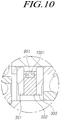
- FIGS. 6 to 10 are cross-sectional views each illustrating a part of a reducer according to embodiments
- FIG. 11 is a cross-sectional view illustrating a part of a reducer according to embodiments
- FIG. 12 shows a cross-sectional view and a side view of a part of the reducer of FIG. 11
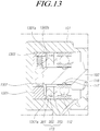
- FIGS. 13 to 14 are cross-sectional views each illustrating a part of a reducer according to embodiments.
- FIGS. 1 and 2 descriptions will be made with reference to FIGS. 1 and 2 .
- a reducer of the electric power assisted steering apparatus 100 (hereinafter, simply referred to as "reducer 100") according to the present embodiment includes a worm shaft 102 having a first end coupled to a damping coupler 104 and rotatably coupled to a first bearing 111 coupled to a housing 101 and a second end rotatably coupled to a second bearing 112 coupled to the housing 101, a damper 113 disposed on an outer race of the second bearing 112 to support the second bearing 112 in an axial direction with respect to the worm shaft 102, and a damper support member 114 or 1301 having a first side contacting the damper 113 to support the damper 113 in the axial direction and a second side disposed on an inner face of the housing 101.
- the worm shaft 102 is engaged with a worm wheel 103 coupled to a steering shaft (not illustrated), and a motor (not illustrated) rotates the worm shaft 102 and transmits assist torque to the steering shaft (not illustrated) so as to assist a driver's steering wheel operation.
- the worm shaft 102 and the motor are connected to each other via the damping coupler 104 including a damper (not illustrated), the first end of the worm shaft 102, which is coupled to the damping coupler 104 is supported by the first bearing 111 coupled to the housing 101 and the second end is supported by the second bearing 112 coupled to the housing 101.
- first bearing 111 and the second bearing 112 which respectively support the first and second ends of the worm shaft 102, are provided to be supported by the housing 101, it is possible to assemble the worm shaft 102 to be engaged with the worm wheel 103 with constant rotational torque by measuring the distance between axes of the worm shaft 102 and the worm wheel 103 with reference to a straight line connecting the centers of the first bearing 111 and the second bearing 112.
- the damper 113 is axially supported on the outer race of the second bearing 112.
- the damper support member 114 or 1301 is supported by the damper 113 on the side opposite the second bearing 112, and acts as a stopper when the damper 113 buffers the axial and radial movements of the worm shaft 102.
- the damper support member 114 or 1301 is axially supported on the damper 113, and the second side is supported on the inner face of the housing 101.
- the damper support member 114 is hollow and includes a through hole 114a, and a third bearing 115 is provided inside the damper support member 114 such that the clearance compensation mechanism 116 is able to compress the worm shaft 102 (see FIG. 3 ).
- the damper support member 1301 may include a hole 1301c into which a rotation support member 1302 is inserted, and the clearance compensation member 1303 is able to press the worm shaft 102 (see FIG. 13 ). Details will be described later.
- an elastic body 117 may be disposed between the inner race of the second bearing 112 and the outer peripheral face of the worm shaft 102. The radial movement of the worm shaft 102 is buffered by the elastic body 117, so that noise is reduced.
- the inner race of the second bearing 112 and the outer peripheral face of the worm shaft 102 may be radially spaced apart from each other in a radial direction wit respect to the worm shaft 102.
- the clearance compensation mechanism 116 or the clearance compensation member 1303 compresses the worm shaft 102 in the direction in which the worm shaft 102 is engaged with the worm wheel 103, the second end of the worm shaft 102 is rotated with respect to the first end thereof, which is supported by the first bearing 111, so the clearance occurring due to wear can be compensated.
- the worm shaft 102 includes a groove 118 disposed on the outer peripheral face thereof in the circumferential direction, and the elastic body 117 can be inserted into the groove 118.
- the elastic body 117 a component having a circular shape like an O-ring to have a rigidity may be used.
- the damper 113 may include a first support portion or member 301 supported by the damper support member 114 or 1301, a second support portion or member 303 supporting the outer race of the second bearing 112, and a damping portion or member 302 provided between the first support portion or member 301 and the second support portion or member 303.
- the damping portion or member 302 provided between the first support portion or member 301 and the second support portion or member 303 is compressed or tensioned to absorb the axial and radial movements of the worm shaft 102.
- the damping portion or member 302 is required to be formed of a material having predetermined warpage, elasticity, and rigidity and capable of absorbing vibration and noise, it may be formed of an elastic material, such as natural rubber (NR), nitrile butadiene rubber (NBR), chloroprene rubber (CR), ethylene propylene erpolymer (EPDM), fluoro rubber (FPM), styrene butadiene rubber (SBR), chlorosulphonated polyethylene (CSM), urethane, silicone, and the like, which have the above properties.
- NR natural rubber
- NBR nitrile butadiene rubber
- CR chloroprene rubber
- EPDM ethylene propylene erpolymer
- FPM fluoro rubber
- SBR styrene butadiene rubber
- CSM chlorosulphonated polyethylene
- the damping portion or member 302 may be provided between the inner diameter portions of the first support portion or member 301 and the second support portion or member 303, or the circumferential grooves 601 or the like may be disposed on the outer peripheral face of the damping portion or member 302.
- the damping portion or member 302 may be disposed between the inner diameter portions of the first support portion or member 301 and the second support portion or member 303 of the damper 113.
- the damper support member 114 is hollow or the damper support member 1301 includes a protrusion 1301a, so that the outer diameter portion of the first support portion or member 301 is axially supported on the damper support member 114 or 1301 and the second support portion or member 303 is axially supported on the outer race of the second bearing 112.
- the damping portion or member 302 is provided between the inner diameter portions of the first support portion or member 301 and the second support portion or member 303, and when a radial movement is generated in the worm shaft 102, the compressed or tensioned degree of the damping portion or member 302 is reduced so that the radial load applied to the worm shaft 102 can be reduced.
- the outer diameter portion of the damper 113 is deformed more greatly than the inner diameter portion of the damper 113 when the axial and radial movements of the worm shaft 102 occur.
- the width L1 in the outer diameter portion is deformed more greatly than the width L2 in the inner diameter portion.
- each of the first support portion or member 301 and the second support portion or member 303 of the damper 113 may include stepped portion 602 disposed on the outer faces of the first suppor portion or member 301 and the second support portion or member 303.
- the stepped portions 602 are configured such that the inner diameter side thicknesses of the first support portion or member 301 and the second support portion or member 303 are thinner than the outer diameter side thicknesses.
- the inner diameter portions of the first support portion or member 301 and the second support portion or member 303 are axially spaced apart from the inner races of the damper support member 114 or 1301 and the second bearing 112, respectively.
- the third bearing 115, or the like due to the movement of the worm shaft 102.
- the damping portion or member 302 may include circumferential grooves 601 disposed on the outer peripheral face of the damping portion or member 302 such that the outer diameter side of the damping portion or member 302 has lower rigidity than the inner diameter side and can be easily deformed in the radial direction.
- the damping portion or member 302 may include two or more circumferential grooves 601. That is, two or more circumferential grooves 601 may be configured to be axially spaced apart from each other so as to reduce the rigidity of the outer diameter side of the damper 113.
- the damping portion or member 302 may be configured such that the outer peripheral face thereof is convex in the radial direction (see reference numeral 701).
- the damping portion or member 302 may include a hollow portion 801 configured therein and disposed at the outer diameter side of the dampling portion or member 302, so that the rigidity of the damper 113 at the outer diameter side may be reduced.
- the damper 113 may include a filler or filling member 901 or 1001 made of a material having rigidity smaller than that of the damping portion or member 302 and provided in the curcumferential grooves 601 or the hollow porton 801. Thus, it may be possible to compensate for the axial rigidity of the damper 113.
- the filler or filling member 901 or 1001 is required to be formed of a material having predetermined warpage, elasticity, and rigidity and capable of absorbing vibration and noise, it may be formed of an elastic material, such as natural rubber(NR), nitrile butadiene rubber (NBR), chloroprene rubber (CR), ethylene propylene erpolymer (EPDM), fluoro rubber (FPM), styrene butadiene rubber (SBR), chlorosulphonated polyethylene (CSM), urethane, silicone, and the like, which have the above properties.
- an elastic material such as natural rubber(NR), nitrile butadiene rubber (NBR), chloroprene rubber (CR), ethylene propylene erpolymer (EPDM), fluoro rubber (FPM), styrene butadiene rubber (SBR), chlorosulphonated polyethylene (CSM), urethane, silicone, and the like, which have the above properties.
- the damping portion or member 302 which is provided in the circumferential grooves 601 or the hollow portion 801, is relatively more greatly deformed at the outer diameter side thereof when the damping portion or member 302 is deformed in the radial direction, it is possible to reduce the radial load applied to the worm shaft 102 by lowering the rigidity on the outer diameter side of the damper 113 due to the circumferential grooves 601 or the like.
- the clearance compensation mechanism 116 or the clearance compensation member 1303 is provided to compensate for the clearance between the worm shaft 102 and the worm wheel 103, which occurs due to wear.
- Embodiments including the clearance compensation mechanism 116 will be described first, and then embodiments including the clearance compensation member 1303 will be described.
- the damper support member 114 has a hollow shape, and the second end of the worm shaft 102 may be coupled with a third bearing 115 disposed inside the damper support member 114.
- the damper support member 114 is hollow and is supported by the outer diameter portion of the first support portion or member 301, even if axial and radial movements of the worm shaft 102 occur, the noise, which may be generated when the inner diameter portion of the first support portion or member 301 collides with the damper support member 114, is prevented from being generated.
- the damper support member 114 includes a through hole 114a penetrating the inner peripheral face and the outer peripheral face of the damper support member 114 in a direction in which the worm shaft 102 and the worm wheel 103 are engaged with each other.
- the clearance compensation mechanism 116 is coupled to the housing 101, and compresses the third bearing 115 through the first bearing 114a.
- the inner diameter of the damper support member 114 is larger than the outer diameter of the third bearing 115.
- the damper support member 114 may include bearing support portions 1101 protruding at the positions from the through hole 114ain the circumferential direction to support third bearing 115, so that the third bearing 115 can be slid while being supported by the clearance compensation mechanism 116 in the direction in which the worm shaft 102 and the worm wheel 103 are engaged with each other.
- the bearing support portions 1101 protrude from the inner circumferential face of the damper support member 114 so as to face each other.
- the third bearing 115 is slid in the direction in which the worm shaft 102 and the worm wheel 103 are engaged with each other while being supported by the bearing support portions 1101 on the opposite sides thereof, and the clearance compensation mechanism 116 compensates for the clearance caused due to wear while compressing the third bearing 115 through the through hole 115.
- the clearance compensation mechanism 116 includes a compression member 201 inserted into the through hole 114a of the damper support member 114 and compressing third bearing 115, a coupling member 203 coupled to the housing 101, and an elastic member 202 having elasticity and disposed between the compression member 201 and the coupling member 203.
- the clearance compensation mechanism 116 is provided in a coupling hole 101a disposed in the housing 101 (see FIG. 2 ).
- One end of the compression member 201 passes through the through hole 114a and is supported on the third bearing 115, and the elastic member 202 and the compression member 201 are slidably inserted into the coupling member 203 and are coupled (e.g., screwed) to the coupling hole 101a.
- the damper support member 1301 may include a hole 1301c elongated in the direction in which the worm shaft 102 and the worm wheel 103 are engaged with each other, and the second end of the worm shaft 102 may be coupled with a rotation support member 1302, which is inserted into the hole 1301c of the damper suppor member 114. That is, the rotation support member 1302 includes an insertion hole 1302b which passes through the central portion thereof in the axial direction, and the second end of the worm shaft 102 is inserted into the insertion hole 1302b.
- the rotation support member 1302 is slidably supported in the hole 1301c, and the hole 1301c is provided with a clearance compensation member 1303, which includes a first end coupled to the rotation support member 1302 and a second end coupled to the damper support member 1301 and elastically supports the rotation support member 1302, so that the worm shaft 102 is compressed by the clearance compensation member 1303 in the direction in which the worm shaft 102 is engaged with the worm wheel 103.
- a coil spring or the like may be used as illustrated in the drawings.
- the rotation support member 1302 may include an insertion portion 1302a configured to protrude, and the damper support member 1301 may include a seating portion 1301b configured to be recessed.
- the damper support member 1301 may include a protrusion 1301a protruding in the axial direction to support the damper 113.
- the protrusion 1301a is provided so as to be supported by the outer diameter portion of the first support portion or member 301, so that even if the axial and radial movements of the worm shaft 102 are generated, it is possible to prevent the occurrence of noise, which is generated when the inner diameter portion of the first support portion or member 301 collides with the damper support member 1301.
Landscapes
- Engineering & Computer Science (AREA)
- General Engineering & Computer Science (AREA)
- Mechanical Engineering (AREA)
- Chemical & Material Sciences (AREA)
- Combustion & Propulsion (AREA)
- Transportation (AREA)
- Physics & Mathematics (AREA)
- Acoustics & Sound (AREA)
- Aviation & Aerospace Engineering (AREA)
- Power Steering Mechanism (AREA)
- Gear Transmission (AREA)
Abstract
Description
- This application claims priority from Korean Patent Application No.
10-2018-0056840, filed on May 18, 2018 - Embodiments disclosed herein relate to a reducer of an electric power steering apparatus, and more particularly, to a reducer of an electric power steering apparatus, in which bearings supported at the opposite ends of a worm shaft are supported by a housing, which makes it possible to assemble the worm shaft with a constant rotational torque at a precise position with respect to the centers of the bearings at the both ends, and in which rotational torque and noise caused by friction between the worm shaft and the worm wheel are reduced by buffering axial and radial movements of the worm shaft and reducing the load applied to the worm shaft in the direction in which the worm shaft is engaged with a worm wheel, whereby a pleasant steering feeing can be provided.
- A conventional reducer of an electric power steering apparatus has a structure, in which a worm shaft having a worm disposed on the outer circumference thereof is engaged with a worm wheel coupled to a steering shaft, and the worm shaft is connected to a motor via a damping coupler such that the torque of the motor is transmitted to the steering shaft, thereby assisting a driver's steering wheel operation.
- In addition, bearings are provided at the opposite ends of an worm shaft in order to support the rotation of the worm shaft, bearings are provided at the opposite ends of the worm shaft. A clearance compensation mechanism is provided to support the worm shaft in the direction in which the work shaft is engaged with the worm wheel in order to reduce noise occurring due to the wear of the worm wheel.
- The clearance compensation mechanism is provided to support a bearing provided on the side opposite the motor. In order to smoothly compensate for the clearance, the bearing on the side opposite the motor needs to be mounted to be slidable in a direction in which the worm shaft and the worm wheel are engaged with each other.
- Therefore, since the bearings supporting the rotation of the worm shaft are not fixed to the housing, it is difficult to accurately set the assembly position during the assembly of the worm shaft and it also is difficult to assemble the worm shaft with constant rotational torque.
- In addition, the damper is provided in order to buffer the axial and radial movements of the worm shaft. However, the load applied to the damper supporting the worm shaft when the worm shaft is moved in the radial direction generates rotational torque and noise due to friction between the worm shaft and the worm wheel.
- Embodiments disclosed herein have been made in view of the foregoing, and aim to make it possible to assemble a worm shaft with constant rotational torque at an accurate position with respect to the centers of the bearings at the opposite ends by making the bearings supported by the housing at the opposite ends of the worm shaft.
- In addition, embodiments disclosed herein aim to provide a pleasant steering feeling by reducing the rotational torque and noise generated due to friction between a worm shaft and a worm wheel by buffering the axial and radial movements of the worm shaft and reducing the load applied to the worm shaft in the direction in which the worm shaft is engaged with the worm wheel.
- The aspect of the present disclosure is not limited thereto, and other unmentioned aspects of the present disclosure may be clearly appreciated by those skilled in the art from the following descriptions.
- Embodiments disclosed herein provide a reducer of an electric power steering apparatus that includes:
a worm shaft having a first end coupled to a damping coupler and rotatably coupled to a first bearing coupled to a housing and a second end rotatably coupled to a second bearing coupled to the housing; a damper disposed on an outer race of the second bearing to support the second bearing in an axial direction with respect to the worm shaft; and a damper support member having a first side contacting the damper to support the damper in the axial direction and a second side disposed on an inner face of the housing. - According to embodiments disclosed herein, since the bearings are supported by the housing at the opposite ends of the worm shaft, it is possible to assemble the worm shaft with constant rotational torque at an accurate position with respect to the centers of the bearings at the opposite ends.
- In addition, by buffering the axial and radial movements of the worm shaft and reducing the load applied to the worm shaft in the direction in which the worm shaft is engaged with the worm wheel, the rotational torque and noise generated due to friction between the worm shaft and the worm wheel are reduced, whereby a pleasant steering feeling can be provided.
- The above and other aspects, features and advantages of the present disclosure will be more apparent from the following detailed description taken in conjunction with the accompanying drawings, in which:
-
FIG. 1 is a cross-sectional view illustrating a part of a reducer of an electric power steering apparatus (hereinafter, simply referred to as "reducer") according to embodiments; -
FIG. 2 is an exploded perspective view of the reducer ofFIG. 1 ; -
FIG. 3 is a cross-sectional view illustrating a part of a reducer according to embodiments; -
FIG. 4 is an exploded perspective view of a part of the reducer ofFIG. 1 ; -
FIG. 5 shows cross-sectional views illustrating an operating state of a part of the reducer ofFIG. 1 ; -
FIGS. 6 to 10 are cross-sectional views each illustrating a part of a reducer according to embodiments; -
FIG. 11 is a cross-sectional view illustrating a part of a reducer according to embodiments; -
FIG. 12 shows a cross-sectional view and a side view of a part of the reducer ofFIG. 11 ; and -
FIGS. 13 to 14 are cross-sectional views each illustrating a part of a reducer according to embodiments. - Hereinafter, embodiments of the present disclosure will be described in detail with reference to the accompanying drawings. In adding reference numerals to elements in each drawing, the same elements will be designated by the same reference numerals, if possible, although they are shown in different drawings. Further, in the following description of the present disclosure, a detailed description of known functions and configurations incorporated herein will be omitted when it may make the subject matter of the present disclosure rather unclear.
- In addition, terms, such as first, second, A, B, (a), (b) or the like may be used herein when describing components of the present disclosure. These terms are merely used to distinguish one structural element from other structural elements, and a property, an order, a sequence and the like of a corresponding structural element are not limited by the term. It should be noted that if it is described in the specification that one component is "connected," "coupled" or "joined" to another component, a third component may be "connected," "coupled," and "joined" between the first and second components, although the first component may be directly connected, coupled or joined to the second component.
-
FIG. 1 is a cross-sectional view illustrating a part of a reducer of an electric power steering apparatus according to embodiments,FIG. 2 is an exploded perspective view of the reducer ofFIG. 1 ,FIG. 3 is a cross-sectional view illustrating a part of a reducer according to embodiments,FIG. 4 is an exploded perspective view of a part of the reducer ofFIG. 1 ,FIG. 5 shows cross-sectional views illustrating an operating state of a part of the reducer ofFIG. 1 ,FIGS. 6 to 10 are cross-sectional views each illustrating a part of a reducer according to embodiments,FIG. 11 is a cross-sectional view illustrating a part of a reducer according to embodiments,FIG. 12 shows a cross-sectional view and a side view of a part of the reducer ofFIG. 11 , andFIGS. 13 to 14 are cross-sectional views each illustrating a part of a reducer according to embodiments. - Hereinafter, descriptions will be made with reference to
FIGS. 1 and2 . - A reducer of the electric power assisted steering apparatus 100 (hereinafter, simply referred to as "
reducer 100") according to the present embodiment includes
aworm shaft 102 having a first end coupled to a dampingcoupler 104 and rotatably coupled to afirst bearing 111 coupled to ahousing 101 and a second end rotatably coupled to asecond bearing 112 coupled to thehousing 101, adamper 113 disposed on an outer race of thesecond bearing 112 to support the second bearing 112 in an axial direction with respect to theworm shaft 102, and adamper support member damper 113 to support thedamper 113 in the axial direction and a second side disposed on an inner face of thehousing 101. - The
worm shaft 102 is engaged with aworm wheel 103 coupled to a steering shaft (not illustrated), and a motor (not illustrated) rotates theworm shaft 102 and transmits assist torque to the steering shaft (not illustrated) so as to assist a driver's steering wheel operation. - The
worm shaft 102 and the motor are connected to each other via thedamping coupler 104 including a damper (not illustrated), the first end of theworm shaft 102, which is coupled to the dampingcoupler 104 is supported by thefirst bearing 111 coupled to thehousing 101 and the second end is supported by thesecond bearing 112 coupled to thehousing 101. - That is, since the first bearing 111 and the second bearing 112, which respectively support the first and second ends of the
worm shaft 102, are provided to be supported by thehousing 101, it is possible to assemble theworm shaft 102 to be engaged with theworm wheel 103 with constant rotational torque by measuring the distance between axes of theworm shaft 102 and theworm wheel 103 with reference to a straight line connecting the centers of the first bearing 111 and the second bearing 112. - The
damper 113 is axially supported on the outer race of the second bearing 112. Thedamper support member damper 113 on the side opposite the second bearing 112, and acts as a stopper when thedamper 113 buffers the axial and radial movements of theworm shaft 102. - That is, the first side of the
damper support member damper 113, and the second side is supported on the inner face of thehousing 101. According to an embodiment, thedamper support member 114 is hollow and includes a throughhole 114a, and a third bearing 115 is provided inside thedamper support member 114 such that theclearance compensation mechanism 116 is able to compress the worm shaft 102 (seeFIG. 3 ). According to another embodiment, thedamper support member 1301 may include ahole 1301c into which arotation support member 1302 is inserted, and theclearance compensation member 1303 is able to press the worm shaft 102 (seeFIG. 13 ). Details will be described later. - Referring to
FIG. 3 , anelastic body 117 may be disposed between the inner race of the second bearing 112 and the outer peripheral face of theworm shaft 102. The radial movement of theworm shaft 102 is buffered by theelastic body 117, so that noise is reduced. - As the
elastic body 117 is provided, the inner race of the second bearing 112 and the outer peripheral face of theworm shaft 102 may be radially spaced apart from each other in a radial direction wit respect to theworm shaft 102. Thus, when theclearance compensation mechanism 116 or theclearance compensation member 1303 compresses theworm shaft 102 in the direction in which theworm shaft 102 is engaged with theworm wheel 103, the second end of theworm shaft 102 is rotated with respect to the first end thereof, which is supported by the first bearing 111, so the clearance occurring due to wear can be compensated. - The
worm shaft 102 includes agroove 118 disposed on the outer peripheral face thereof in the circumferential direction, and theelastic body 117 can be inserted into thegroove 118. As theelastic body 117, a component having a circular shape like an O-ring to have a rigidity may be used. - Meanwhile, referring to
FIG. 4 , thedamper 113 may include a first support portion ormember 301 supported by thedamper support member member 303 supporting the outer race of the second bearing 112, and a damping portion ormember 302 provided between the first support portion ormember 301 and the second support portion ormember 303. - That is, the damping portion or
member 302 provided between the first support portion ormember 301 and the second support portion ormember 303 is compressed or tensioned to absorb the axial and radial movements of theworm shaft 102. - Since the damping portion or
member 302 is required to be formed of a material having predetermined warpage, elasticity, and rigidity and capable of absorbing vibration and noise, it may be formed of an elastic material, such as natural rubber (NR), nitrile butadiene rubber (NBR), chloroprene rubber (CR), ethylene propylene erpolymer (EPDM), fluoro rubber (FPM), styrene butadiene rubber (SBR), chlorosulphonated polyethylene (CSM), urethane, silicone, and the like, which have the above properties. - At this time, in order to prevent an increase in the rotational torque and the generation of noise due to the friction between the
worm shaft 102 and theworm wheel 103 by the radial elastic force applied to theworm shaft 102 by thedamper 113 being compressed or tensioned, the damping portion ormember 302 may be provided between the inner diameter portions of the first support portion ormember 301 and the second support portion ormember 303, or thecircumferential grooves 601 or the like may be disposed on the outer peripheral face of the damping portion ormember 302. - That is, not only the elastic force of the
clearance compensation mechanism 116 or theclearance compensation member 1303 but also the elastic force of thedamper 113 is applied to theworm shaft 102 in the direction in which theworm shaft 102 is engaged with theworm wheel 103. Thus, in order to reduce rotational torque and noise caused due to friction, it is necessary to reduce the radial load applied to theworm shaft 102 by thedamper 113. - First, the damping portion or
member 302 may be disposed between the inner diameter portions of the first support portion ormember 301 and the second support portion ormember 303 of thedamper 113. - Referring to
FIG. 3 , thedamper support member 114 is hollow or thedamper support member 1301 includes aprotrusion 1301a, so that the outer diameter portion of the first support portion ormember 301 is axially supported on thedamper support member member 303 is axially supported on the outer race of thesecond bearing 112. - At this time, the damping portion or
member 302 is provided between the inner diameter portions of the first support portion ormember 301 and the second support portion ormember 303, and when a radial movement is generated in theworm shaft 102, the compressed or tensioned degree of the damping portion ormember 302 is reduced so that the radial load applied to theworm shaft 102 can be reduced. - That is, since the outer diameter portions of the first
support portion member 301 and the second support portion ormember 303 are axially supported on thedamper support member second bearing 112, the outer diameter portion of thedamper 113 is deformed more greatly than the inner diameter portion of thedamper 113 when the axial and radial movements of theworm shaft 102 occur. - In other words, referring to
FIG. 5 , when compared with the width L0 between the first support portion ormember 301 and the second support portion ormember 303 before thedamper 113 is deformed, after the deformation of thedamper 113, the width L1 in the outer diameter portion is deformed more greatly than the width L2 in the inner diameter portion. - Meanwhile, each of the first support portion or
member 301 and the second support portion ormember 303 of thedamper 113 may include steppedportion 602 disposed on the outer faces of the first suppor portion ormember 301 and the second support portion ormember 303. As illustrated in the drawing, the steppedportions 602 are configured such that the inner diameter side thicknesses of the first support portion ormember 301 and the second support portion ormember 303 are thinner than the outer diameter side thicknesses. - Due to the stepped
portions 602, the inner diameter portions of the first support portion ormember 301 and the second support portion ormember 303 are axially spaced apart from the inner races of thedamper support member second bearing 112, respectively. Thus, it is possible to prevent occurrence of noise, which occurs when the first support portion ormember 301 or the second support portion ormember 303 collides with the inner race of thesecond bearing 112, thethird bearing 115, or the like due to the movement of theworm shaft 102. - Next, referring to
FIG. 6 , the damping portion ormember 302 may includecircumferential grooves 601 disposed on the outer peripheral face of the damping portion ormember 302 such that the outer diameter side of the damping portion ormember 302 has lower rigidity than the inner diameter side and can be easily deformed in the radial direction. - The damping portion or
member 302 may include two or morecircumferential grooves 601. That is, two or morecircumferential grooves 601 may be configured to be axially spaced apart from each other so as to reduce the rigidity of the outer diameter side of thedamper 113. - Alternatively, as illustrated in
FIG. 7 , the damping portion ormember 302 may be configured such that the outer peripheral face thereof is convex in the radial direction (see reference numeral 701). Or, as illustrated inFIG. 8 , the damping portion ormember 302 may include ahollow portion 801 configured therein and disposed at the outer diameter side of the dampling portion ormember 302, so that the rigidity of thedamper 113 at the outer diameter side may be reduced. - Meanwhile, as illustrated in
FIGS. 9 to 10 , thedamper 113 may include a filler or fillingmember member 302 and provided in thecurcumferential grooves 601 or thehollow porton 801. Thus, it may be possible to compensate for the axial rigidity of thedamper 113. - Since the filler or filling
member - Since the damping portion or
member 302, which is provided in thecircumferential grooves 601 or thehollow portion 801, is relatively more greatly deformed at the outer diameter side thereof when the damping portion ormember 302 is deformed in the radial direction, it is possible to reduce the radial load applied to theworm shaft 102 by lowering the rigidity on the outer diameter side of thedamper 113 due to thecircumferential grooves 601 or the like. - As described above, the
clearance compensation mechanism 116 or theclearance compensation member 1303 is provided to compensate for the clearance between theworm shaft 102 and theworm wheel 103, which occurs due to wear. Embodiments including theclearance compensation mechanism 116 will be described first, and then embodiments including theclearance compensation member 1303 will be described. - First, referring to
FIGS. 3 ,11 , and12 , thedamper support member 114 has a hollow shape, and the second end of theworm shaft 102 may be coupled with athird bearing 115 disposed inside thedamper support member 114. - Since the
damper support member 114 is hollow and is supported by the outer diameter portion of the first support portion ormember 301, even if axial and radial movements of theworm shaft 102 occur, the noise, which may be generated when the inner diameter portion of the first support portion ormember 301 collides with thedamper support member 114, is prevented from being generated. - The
damper support member 114 includes a throughhole 114a penetrating the inner peripheral face and the outer peripheral face of thedamper support member 114 in a direction in which theworm shaft 102 and theworm wheel 103 are engaged with each other. Theclearance compensation mechanism 116 is coupled to thehousing 101, and compresses thethird bearing 115 through thefirst bearing 114a. - The inner diameter of the
damper support member 114 is larger than the outer diameter of thethird bearing 115. Thedamper support member 114 may include bearingsupport portions 1101 protruding at the positions from the through hole 114ain the circumferential direction to supportthird bearing 115, so that thethird bearing 115 can be slid while being supported by theclearance compensation mechanism 116 in the direction in which theworm shaft 102 and theworm wheel 103 are engaged with each other. - That is, the bearing
support portions 1101 protrude from the inner circumferential face of thedamper support member 114 so as to face each other. Thethird bearing 115 is slid in the direction in which theworm shaft 102 and theworm wheel 103 are engaged with each other while being supported by the bearingsupport portions 1101 on the opposite sides thereof, and theclearance compensation mechanism 116 compensates for the clearance caused due to wear while compressing thethird bearing 115 through the throughhole 115. - The
clearance compensation mechanism 116 includes acompression member 201 inserted into the throughhole 114a of thedamper support member 114 and compressingthird bearing 115, acoupling member 203 coupled to thehousing 101, and anelastic member 202 having elasticity and disposed between thecompression member 201 and thecoupling member 203. - The
clearance compensation mechanism 116 is provided in acoupling hole 101a disposed in the housing 101 (seeFIG. 2 ). One end of thecompression member 201 passes through the throughhole 114a and is supported on thethird bearing 115, and theelastic member 202 and thecompression member 201 are slidably inserted into thecoupling member 203 and are coupled (e.g., screwed) to thecoupling hole 101a. - Next, referring to
FIGS. 13 and14 , thedamper support member 1301 may include ahole 1301c elongated in the direction in which theworm shaft 102 and theworm wheel 103 are engaged with each other, and the second end of theworm shaft 102 may be coupled with arotation support member 1302, which is inserted into thehole 1301c of thedamper suppor member 114. That is, therotation support member 1302 includes aninsertion hole 1302b which passes through the central portion thereof in the axial direction, and the second end of theworm shaft 102 is inserted into theinsertion hole 1302b. - The
rotation support member 1302 is slidably supported in thehole 1301c, and thehole 1301c is provided with aclearance compensation member 1303, which includes a first end coupled to therotation support member 1302 and a second end coupled to thedamper support member 1301 and elastically supports therotation support member 1302, so that theworm shaft 102 is compressed by theclearance compensation member 1303 in the direction in which theworm shaft 102 is engaged with theworm wheel 103. - As the
clearance compensation member 1303, a coil spring or the like may be used as illustrated in the drawings. - In order to prevent the
clearance compensation member 1303 from escaping from thehole 1301c, therotation support member 1302 may include aninsertion portion 1302a configured to protrude, and thedamper support member 1301 may include aseating portion 1301b configured to be recessed. - The
damper support member 1301 may include aprotrusion 1301a protruding in the axial direction to support thedamper 113. - That is, the
protrusion 1301a is provided so as to be supported by the outer diameter portion of the first support portion ormember 301, so that even if the axial and radial movements of theworm shaft 102 are generated, it is possible to prevent the occurrence of noise, which is generated when the inner diameter portion of the first support portion ormember 301 collides with thedamper support member 1301. - According to the reducer on electric power steering apparatus, which has the shapes described above, since the bearings are supported by the housing at the opposite ends of the worm shaft, it is possible to assemble the worm shaft with constant rotational torque at an accurate position with respect to the centers of the bearings at the opposite ends.
- In addition, by buffering the axial and radial movements of the worm shaft and reducing the load applied to the worm shaft in the direction in which the worm shaft is engaged with the worm wheel, the rotational torque and noise generated due to friction between the worm shaft and the worm wheel are reduced, whereby a pleasant steering feeling can be provided.
- Although all the elements constituting embodiments of the present disclosure have been described above as being combined into a single unit or combined to be operated as a single unit, the present disclosure is not necessarily limited to such embodiments. That is, at least two elements of all structural elements may be selectively joined and operate without departing from the scope of the present disclosure.
- In addition, since terms, such as "including," "comprising," and "having" mean that one or more corresponding components may exist unless they are specifically described to the contrary, it shall be construed that one or more other components can be included. All the terms that are technical, scientific or otherwise agree with the meanings as understood by a person skilled in the art unless defined to the contrary. Common terms as found in dictionaries should be interpreted in the context of the related technical writings not too ideally or impractically unless the present disclosure expressly defines them so.
- The above embodiments have been described merely for the purpose of illustrating the technical idea of the present disclosure, and those skilled in the art will appreciate that various modifications and changes are possible without departing from the scope and spirit of the present disclosure. Therefore, the embodiments disclosed in the present disclosure are intended to illustrate the scope of the technical idea of the present disclosure, and the scope of the present disclosure is not limited by the embodiment. The scope of the present disclosure shall be construed on the basis of the accompanying claims in such a manner that all of the technical ideas included within the scope equivalent to the claims belong to the present disclosure.
Claims (15)
- A reducer (100) of an electric power steering apparatus, the reducer (100) comprising:a worm shaft (100) having a first end coupled to a damping coupler (104) and rotatably coupled to a first bearing (111) coupled to a housing and a second end rotatably coupled to a second bearing (112) coupled to the housing;a damper (113) disposed on an outer race of the second bearing to support the second bearing in an axial direction with respect to the worm shaft (100); anda damper support member (114) having a first side contacting the damper (113) to support the damper (113) in the axial direction and a second side disposed on an inner face of the housing.
- The reducer (100) of claim 1, further comprising:
an elastic body disposed between an inner race of the second bearing and an outer peripheral face of the worm shaft (102). - The reducer (100) of claim 2, wherein the inner race of the second bearing and the outer peripheral face of the worm shaft (102) are spaced apart from each other in a radial direction with respect to the worm shaft (102).
- The reducer (100) of one of claims 1 to 3, wherein the damper (113) comprises a first support portion supported by the damper support member, a second support portion supporting the outer race of the second bearing, and a damping portion disposed between the first support portion and the second support portion.
- The reducer (100) of claim 4, wherein the damping portion of the damper (113) is disposed between inner radial portions of the first and second support portions of the damper (113).
- The reducer (100) of claim 4 or 5, wherein each of the first and second support portions of the damper (113) comprises a stepped portion disposed on outer faces of each of the first and second support portions.
- The reducer (100) of one of claims 4 to 6, wherein the damping portion of the damper (113) comprises a circumferential groove disposed on an outer peripheral face of the damping portionor the damping portion of the damper (113) comprises two or more circumferential grooves and/or the damper (113) comprises a filler made of material having rigidity smaller than rigidity of the damping portion of the damper (113) and disposed in the circumferential grooves and/or the damping portion of the damper (113) has an outer peripheral face, which is radially convex or.
the damping portion of the damper (113) comprises a hollow portion disposed inside the damping portion and disposed at an outer diameter side of the damping portion. - The reducer (100) of claim 7, wherein the damper (113) comprises a filler made of material having rigidity smaller than rigidity of the damping portion of the damper (113) and provided in the hollow portion.
- The reducer (100) of one of claims 1 to 3, wherein the damper support member has a hollow shape, and the second end of the worm shaft (102) is coupled with a third bearing disposed inside the damper support member.
- The reducer (100) of claim 9, wherein the damper support member comprises a through hole penetrating inner and outer peripheral faces of the damper support member in a direction in which the worm shaft (100) and the worm wheel are engaged with each other.
- The reducer (100) of claim 10, wherein the damper support member comprises bearing support portions protruding at positions spaced from the through hole in a circumferential direction to support the third bearing or
further comprising a clearance compensation mechanism coupled to the housing and inserted into the through hole of the damper support member to compress the third bearing. - The reducer (100) of claim 11, wherein the clearance compensation mechanism comprises a compression member inserted into the through hole of the damper support member and compressing the third bearing, a coupling member coupled to the housing, and an elastic member having elasticity and disposed between the compression member and the coupling member.
- The reducer (100) of one of claims 1 to 3, wherein the damper support member comprises a hole elongated in a direction in which the worm shaft (102) and the worm wheel are engaged with each other, and the second end of the worm shaft (102) is coupled with a rotation support member inserted into the hole of the damper support member.
- The reducer (100) of claim 13, further comprising a clearance compensation member disposed in the hole of the damper support member, the clearance compensation member comprising a first end coupled to the rotation support member and a second end coupled to the damper support member, wherein the clearance compensation member is configured to compress the rotation support member.
- The reducer (100) of claim 13 or 14, wherein the damper support member comprises a protrusion protruding in the axial direction to support the damper (113).
Applications Claiming Priority (1)
| Application Number | Priority Date | Filing Date | Title |
|---|---|---|---|
| KR1020180056840A KR102033558B1 (en) | 2018-05-18 | 2018-05-18 | Reducer of Electric power steering apparatus |
Publications (2)
| Publication Number | Publication Date |
|---|---|
| EP3572301A1 true EP3572301A1 (en) | 2019-11-27 |
| EP3572301B1 EP3572301B1 (en) | 2021-07-07 |
Family
ID=66589467
Family Applications (1)
| Application Number | Title | Priority Date | Filing Date |
|---|---|---|---|
| EP19175173.4A Active EP3572301B1 (en) | 2018-05-18 | 2019-05-17 | Reducer of electric power steering apparatus |
Country Status (3)
| Country | Link |
|---|---|
| US (1) | US11346435B2 (en) |
| EP (1) | EP3572301B1 (en) |
| KR (1) | KR102033558B1 (en) |
Families Citing this family (9)
| Publication number | Priority date | Publication date | Assignee | Title |
|---|---|---|---|---|
| KR102540394B1 (en) * | 2018-10-10 | 2023-06-08 | 현대자동차주식회사 | A noise preventing structure of electronic power steering apparatus |
| KR102692481B1 (en) * | 2019-02-12 | 2024-08-07 | 현대자동차주식회사 | Noise reducing apparatus for power steering system |
| US11608111B2 (en) * | 2020-09-04 | 2023-03-21 | R.H. Sheppard Co. Inc. | End of travel relief system for power steering system |
| KR20230036461A (en) * | 2021-09-07 | 2023-03-14 | 에이치엘만도 주식회사 | Damper and apparatus for driving of power steering having the same |
| DE102022100927A1 (en) | 2022-01-17 | 2023-07-20 | Schaeffler Technologies AG & Co. KG | Angular bearing device for angle drive, angle drive and linear drive |
| KR102629274B1 (en) | 2022-01-25 | 2024-01-25 | 에이치엘만도 주식회사 | Reducer for Electric Power Steering Apparatus |
| KR20230116208A (en) * | 2022-01-28 | 2023-08-04 | 에이치엘만도 주식회사 | Damper for electric power steering |
| KR102548351B1 (en) * | 2022-02-04 | 2023-06-27 | (주)신화정공 | Worm Gear Assembly for Azimuth Drive |
| DE102022116984A1 (en) * | 2022-07-07 | 2024-01-18 | Schaeffler Technologies AG & Co. KG | Storage arrangement |
Citations (11)
| Publication number | Priority date | Publication date | Assignee | Title |
|---|---|---|---|---|
| EP0943842A1 (en) * | 1998-03-19 | 1999-09-22 | Mannesmann VDO Aktiengesellschaft | Worm reduction gear |
| EP1065132A1 (en) * | 1999-06-28 | 2001-01-03 | Koyo Seiko Co., Ltd. | Electric power steering apparatus |
| US20040163879A1 (en) * | 2003-02-20 | 2004-08-26 | Toru Segawa | Electric-powered power steering apparatus |
| EP1452419A1 (en) * | 2001-12-03 | 2004-09-01 | Nsk Ltd., | Electric power steering device |
| JP2005088820A (en) * | 2003-09-19 | 2005-04-07 | Hitachi Unisia Automotive Ltd | Electric power steering device |
| US20070102228A1 (en) * | 2003-04-18 | 2007-05-10 | Koyo Seiko Co., Ltd. | Electric power steering device |
| US20100116582A1 (en) * | 2008-11-12 | 2010-05-13 | Mando Corporation | Reducer of electronic power steering apparatus backgound of the invention |
| JP2011110979A (en) * | 2009-11-24 | 2011-06-09 | Mitsubishi Motors Corp | Electric power steering device and method of checking backlash of the same |
| KR20110076112A (en) * | 2009-12-29 | 2011-07-06 | 주식회사 만도 | Reduction gear of electric power assist steering device and electric power assist steering device using same |
| JP2012197028A (en) * | 2011-03-22 | 2012-10-18 | Kyb Co Ltd | Power steering device |
| DE202013102400U1 (en) * | 2013-06-04 | 2013-06-17 | Namyang.Co., Ltd. | Worm shaft shock absorber for electric power steering |
Family Cites Families (45)
| Publication number | Priority date | Publication date | Assignee | Title |
|---|---|---|---|---|
| US6520042B2 (en) * | 1999-10-07 | 2003-02-18 | Delphi Technologies, Inc. | Electric power steering assist mechanism |
| US6523431B2 (en) * | 1999-10-07 | 2003-02-25 | Delphi Technologies, Inc. | Electric power steering assist mechanism |
| JP2002205244A (en) * | 2001-01-11 | 2002-07-23 | Tsudakoma Corp | Indexing device and its assembling method |
| JP3888607B2 (en) * | 2001-03-05 | 2007-03-07 | 本田技研工業株式会社 | Electric power steering device |
| CA2507935A1 (en) * | 2002-12-05 | 2004-06-17 | Koyo Seiko Co., Ltd. | Worm support device and power assist unit having the same |
| JP4442421B2 (en) * | 2002-12-09 | 2010-03-31 | 日本精工株式会社 | Electric power steering device |
| JP4136700B2 (en) * | 2003-02-14 | 2008-08-20 | トヨタ自動車株式会社 | Worm shaft movable amount adjusting method and reduction gear for electric power steering device |
| US20060191736A1 (en) * | 2003-06-25 | 2006-08-31 | Atsushi Maeda | Electric power steering device |
| JP2006175891A (en) * | 2004-12-20 | 2006-07-06 | Favess Co Ltd | Electric power steering device |
| KR20100073550A (en) * | 2008-12-23 | 2010-07-01 | 주식회사 만도 | Reducer of electronic power steering apparatus |
| KR20110009274A (en) * | 2009-07-22 | 2011-01-28 | 주식회사 만도 | Reduction gears in electric power assisted steering |
| KR20110060544A (en) * | 2009-11-30 | 2011-06-08 | 주식회사 만도 | Reduction gear of electric power assist steering device and electric power assist steering device using same |
| US8905185B2 (en) * | 2009-12-23 | 2014-12-09 | Mando Corporation | Reducer of electric power steering apparatus |
| JP5641195B2 (en) * | 2010-04-13 | 2014-12-17 | 株式会社ジェイテクト | Electric power steering device |
| JP5708981B2 (en) * | 2010-09-09 | 2015-04-30 | 株式会社ジェイテクト | Electric power steering device |
| JP5645070B2 (en) * | 2010-11-09 | 2014-12-24 | 株式会社ジェイテクト | Electric power steering device |
| JP5618146B2 (en) * | 2010-12-24 | 2014-11-05 | 株式会社ジェイテクト | Electric power steering device |
| WO2012173096A1 (en) * | 2011-06-16 | 2012-12-20 | 日本精工株式会社 | Electric power steering apparatus |
| KR101298117B1 (en) * | 2011-06-30 | 2013-08-21 | 한국델파이주식회사 | Electric power steering apparatus |
| JP2013071679A (en) * | 2011-09-28 | 2013-04-22 | Showa Corp | Electric power steering device |
| JP5999423B2 (en) * | 2011-11-25 | 2016-09-28 | 株式会社ジェイテクト | Electric power steering device |
| EP2842835A4 (en) * | 2012-04-25 | 2016-04-06 | Jtekt Corp | Electric power steering device |
| KR20140014714A (en) * | 2012-07-25 | 2014-02-06 | 현대모비스 주식회사 | Noise reduction type motor driven power steering |
| KR101410500B1 (en) * | 2012-07-25 | 2014-06-23 | 남양공업주식회사 | Wormshaft damping apparatus of electric power steering |
| US9664273B2 (en) * | 2012-08-07 | 2017-05-30 | Steering Solutions Ip Holding Corporation | Steering column assist system |
| US9533701B2 (en) * | 2012-08-07 | 2017-01-03 | Steering Solutions Ip Holding Corporation | Steering column assist system |
| JP5908380B2 (en) * | 2012-09-24 | 2016-04-26 | 日立オートモティブシステムズステアリング株式会社 | Power steering device and reduction gear for power steering device |
| KR101477906B1 (en) * | 2013-05-28 | 2014-12-30 | 주식회사 만도 | Reducer of Electric Power Steering Apparatus |
| KR101491304B1 (en) * | 2013-08-27 | 2015-02-06 | 주식회사 만도 | Reducer of Electric Power Steering Apparatus |
| KR101759758B1 (en) * | 2013-10-22 | 2017-07-19 | 주식회사 만도 | Reducer of Electric Power Steering Apparatus |
| JP2016064790A (en) * | 2014-09-25 | 2016-04-28 | 株式会社ショーワ | Steering device |
| KR101594305B1 (en) * | 2014-12-04 | 2016-02-17 | 주식회사 만도 | Reducer of Electric Power Steering Apparatus |
| JP6364343B2 (en) * | 2014-12-24 | 2018-07-25 | 株式会社ショーワ | Power steering apparatus and method for adjusting preload thereof |
| KR102281674B1 (en) * | 2015-01-12 | 2021-07-27 | 주식회사 만도 | Reducer for vehicle |
| KR102281681B1 (en) * | 2015-01-12 | 2021-07-27 | 주식회사 만도 | Reducer for vehicle |
| GB201502825D0 (en) * | 2015-02-19 | 2015-04-08 | Trw Ltd | Gearbox for electric assisted steering apparatus |
| US10738834B2 (en) * | 2015-04-28 | 2020-08-11 | Nsk Ltd. | Joint for torque transmission and worm reduction gear |
| JP2016211615A (en) * | 2015-04-30 | 2016-12-15 | 株式会社ジェイテクト | Worm reducer and steering device |
| KR101694279B1 (en) * | 2015-10-27 | 2017-01-11 | 주식회사 만도 | Reducer of Electric Power Steering Apparatus |
| JP6167198B1 (en) * | 2016-03-25 | 2017-07-19 | Kyb株式会社 | Electric power steering device and method of manufacturing electric power steering device |
| JP6646334B2 (en) * | 2016-03-28 | 2020-02-14 | 株式会社ショーワ | Power steering device |
| DE102016006156A1 (en) * | 2016-05-23 | 2017-11-23 | Thyssenkrupp Ag | Electromechanical power steering with swivel bearing for a helical gearbox |
| CN109690131B (en) * | 2016-09-21 | 2022-04-05 | 日本精工株式会社 | Worm gear reducer |
| JP2018155301A (en) * | 2017-03-16 | 2018-10-04 | 株式会社ジェイテクト | Method for manufacturing worm reducer, worm reducer, and electric power steering device |
| JP6876249B2 (en) * | 2017-04-19 | 2021-05-26 | 株式会社ジェイテクト | Warm reducer and electric power steering device |
-
2018
- 2018-05-18 KR KR1020180056840A patent/KR102033558B1/en active Active
-
2019
- 2019-05-17 EP EP19175173.4A patent/EP3572301B1/en active Active
- 2019-05-20 US US16/417,332 patent/US11346435B2/en active Active
Patent Citations (11)
| Publication number | Priority date | Publication date | Assignee | Title |
|---|---|---|---|---|
| EP0943842A1 (en) * | 1998-03-19 | 1999-09-22 | Mannesmann VDO Aktiengesellschaft | Worm reduction gear |
| EP1065132A1 (en) * | 1999-06-28 | 2001-01-03 | Koyo Seiko Co., Ltd. | Electric power steering apparatus |
| EP1452419A1 (en) * | 2001-12-03 | 2004-09-01 | Nsk Ltd., | Electric power steering device |
| US20040163879A1 (en) * | 2003-02-20 | 2004-08-26 | Toru Segawa | Electric-powered power steering apparatus |
| US20070102228A1 (en) * | 2003-04-18 | 2007-05-10 | Koyo Seiko Co., Ltd. | Electric power steering device |
| JP2005088820A (en) * | 2003-09-19 | 2005-04-07 | Hitachi Unisia Automotive Ltd | Electric power steering device |
| US20100116582A1 (en) * | 2008-11-12 | 2010-05-13 | Mando Corporation | Reducer of electronic power steering apparatus backgound of the invention |
| JP2011110979A (en) * | 2009-11-24 | 2011-06-09 | Mitsubishi Motors Corp | Electric power steering device and method of checking backlash of the same |
| KR20110076112A (en) * | 2009-12-29 | 2011-07-06 | 주식회사 만도 | Reduction gear of electric power assist steering device and electric power assist steering device using same |
| JP2012197028A (en) * | 2011-03-22 | 2012-10-18 | Kyb Co Ltd | Power steering device |
| DE202013102400U1 (en) * | 2013-06-04 | 2013-06-17 | Namyang.Co., Ltd. | Worm shaft shock absorber for electric power steering |
Also Published As
| Publication number | Publication date |
|---|---|
| KR102033558B1 (en) | 2019-10-17 |
| EP3572301B1 (en) | 2021-07-07 |
| US11346435B2 (en) | 2022-05-31 |
| US20190353238A1 (en) | 2019-11-21 |
Similar Documents
| Publication | Publication Date | Title |
|---|---|---|
| EP3572301B1 (en) | Reducer of electric power steering apparatus | |
| KR102281674B1 (en) | Reducer for vehicle | |
| CN103998323B (en) | The electrical position control apparatus of steering handwheel | |
| KR102281681B1 (en) | Reducer for vehicle | |
| US9145949B2 (en) | Reducer of electric power steering apparatus | |
| US9199663B2 (en) | Rack-driven auxiliary power steering apparatus | |
| JP6256663B2 (en) | Worm reducer | |
| JP2018192955A (en) | Steering device | |
| WO2011129280A1 (en) | Electric power steering device | |
| US10378639B2 (en) | Reducer of electric power steering apparatus | |
| US11148712B2 (en) | Reducer of electric power steering apparatus | |
| JP2013210005A (en) | Electric power steering device | |
| KR20120027624A (en) | Rack assist type electric power steering apparatus | |
| JP6348306B2 (en) | Electric actuator | |
| JP2019007534A (en) | Worm reducer | |
| JP5471354B2 (en) | Steering device | |
| JP2016155443A (en) | Steering device | |
| JP2012214164A (en) | Rack-and-pinion steering gear unit | |
| KR20120034905A (en) | Rack bar supporting device of steering apparatus for vehicle | |
| JP2018194147A (en) | Worm reducer | |
| JPH0811727A (en) | Rack and pinion type steering device | |
| JP2016217407A (en) | Universal joint | |
| JP2023007883A (en) | Worm reduction gear | |
| JP2020180638A (en) | Ball screw device and steering device | |
| KR20200107493A (en) | Rack Bar Supporting Device of Steering Apparatus for Vehicle |
Legal Events
| Date | Code | Title | Description |
|---|---|---|---|
| PUAI | Public reference made under article 153(3) epc to a published international application that has entered the european phase |
Free format text: ORIGINAL CODE: 0009012 |
|
| STAA | Information on the status of an ep patent application or granted ep patent |
Free format text: STATUS: REQUEST FOR EXAMINATION WAS MADE |
|
| 17P | Request for examination filed |
Effective date: 20190517 |
|
| AK | Designated contracting states |
Kind code of ref document: A1 Designated state(s): AL AT BE BG CH CY CZ DE DK EE ES FI FR GB GR HR HU IE IS IT LI LT LU LV MC MK MT NL NO PL PT RO RS SE SI SK SM TR |
|
| AX | Request for extension of the european patent |
Extension state: BA ME |
|
| RBV | Designated contracting states (corrected) |
Designated state(s): AL AT BE BG CH CY CZ DE DK EE ES FI FR GB GR HR HU IE IS IT LI LT LU LV MC MK MT NL NO PL PT RO RS SE SI SK SM TR |
|
| GRAP | Despatch of communication of intention to grant a patent |
Free format text: ORIGINAL CODE: EPIDOSNIGR1 |
|
| STAA | Information on the status of an ep patent application or granted ep patent |
Free format text: STATUS: GRANT OF PATENT IS INTENDED |
|
| RIC1 | Information provided on ipc code assigned before grant |
Ipc: F16C 27/00 20060101ALI20201112BHEP Ipc: B62D 5/04 20060101AFI20201112BHEP Ipc: F16H 55/24 20060101ALI20201112BHEP |
|
| INTG | Intention to grant announced |
Effective date: 20201207 |
|
| GRAS | Grant fee paid |
Free format text: ORIGINAL CODE: EPIDOSNIGR3 |
|
| GRAA | (expected) grant |
Free format text: ORIGINAL CODE: 0009210 |
|
| STAA | Information on the status of an ep patent application or granted ep patent |
Free format text: STATUS: THE PATENT HAS BEEN GRANTED |
|
| AK | Designated contracting states |
Kind code of ref document: B1 Designated state(s): AL AT BE BG CH CY CZ DE DK EE ES FI FR GB GR HR HU IE IS IT LI LT LU LV MC MK MT NL NO PL PT RO RS SE SI SK SM TR |
|
| REG | Reference to a national code |
Ref country code: GB Ref legal event code: FG4D |
|
| REG | Reference to a national code |
Ref country code: AT Ref legal event code: REF Ref document number: 1408326 Country of ref document: AT Kind code of ref document: T Effective date: 20210715 |
|
| REG | Reference to a national code |
Ref country code: DE Ref legal event code: R096 Ref document number: 602019005861 Country of ref document: DE |
|
| REG | Reference to a national code |
Ref country code: IE Ref legal event code: FG4D |
|
| REG | Reference to a national code |
Ref country code: LT Ref legal event code: MG9D |
|
| REG | Reference to a national code |
Ref country code: NL Ref legal event code: MP Effective date: 20210707 |
|
| REG | Reference to a national code |
Ref country code: AT Ref legal event code: MK05 Ref document number: 1408326 Country of ref document: AT Kind code of ref document: T Effective date: 20210707 |
|
| PG25 | Lapsed in a contracting state [announced via postgrant information from national office to epo] |
Ref country code: ES Free format text: LAPSE BECAUSE OF FAILURE TO SUBMIT A TRANSLATION OF THE DESCRIPTION OR TO PAY THE FEE WITHIN THE PRESCRIBED TIME-LIMIT Effective date: 20210707 Ref country code: FI Free format text: LAPSE BECAUSE OF FAILURE TO SUBMIT A TRANSLATION OF THE DESCRIPTION OR TO PAY THE FEE WITHIN THE PRESCRIBED TIME-LIMIT Effective date: 20210707 Ref country code: RS Free format text: LAPSE BECAUSE OF FAILURE TO SUBMIT A TRANSLATION OF THE DESCRIPTION OR TO PAY THE FEE WITHIN THE PRESCRIBED TIME-LIMIT Effective date: 20210707 Ref country code: SE Free format text: LAPSE BECAUSE OF FAILURE TO SUBMIT A TRANSLATION OF THE DESCRIPTION OR TO PAY THE FEE WITHIN THE PRESCRIBED TIME-LIMIT Effective date: 20210707 Ref country code: HR Free format text: LAPSE BECAUSE OF FAILURE TO SUBMIT A TRANSLATION OF THE DESCRIPTION OR TO PAY THE FEE WITHIN THE PRESCRIBED TIME-LIMIT Effective date: 20210707 Ref country code: NO Free format text: LAPSE BECAUSE OF FAILURE TO SUBMIT A TRANSLATION OF THE DESCRIPTION OR TO PAY THE FEE WITHIN THE PRESCRIBED TIME-LIMIT Effective date: 20211007 Ref country code: NL Free format text: LAPSE BECAUSE OF FAILURE TO SUBMIT A TRANSLATION OF THE DESCRIPTION OR TO PAY THE FEE WITHIN THE PRESCRIBED TIME-LIMIT Effective date: 20210707 Ref country code: PT Free format text: LAPSE BECAUSE OF FAILURE TO SUBMIT A TRANSLATION OF THE DESCRIPTION OR TO PAY THE FEE WITHIN THE PRESCRIBED TIME-LIMIT Effective date: 20211108 Ref country code: AT Free format text: LAPSE BECAUSE OF FAILURE TO SUBMIT A TRANSLATION OF THE DESCRIPTION OR TO PAY THE FEE WITHIN THE PRESCRIBED TIME-LIMIT Effective date: 20210707 Ref country code: BG Free format text: LAPSE BECAUSE OF FAILURE TO SUBMIT A TRANSLATION OF THE DESCRIPTION OR TO PAY THE FEE WITHIN THE PRESCRIBED TIME-LIMIT Effective date: 20211007 Ref country code: LT Free format text: LAPSE BECAUSE OF FAILURE TO SUBMIT A TRANSLATION OF THE DESCRIPTION OR TO PAY THE FEE WITHIN THE PRESCRIBED TIME-LIMIT Effective date: 20210707 |
|
| PG25 | Lapsed in a contracting state [announced via postgrant information from national office to epo] |
Ref country code: PL Free format text: LAPSE BECAUSE OF FAILURE TO SUBMIT A TRANSLATION OF THE DESCRIPTION OR TO PAY THE FEE WITHIN THE PRESCRIBED TIME-LIMIT Effective date: 20210707 Ref country code: LV Free format text: LAPSE BECAUSE OF FAILURE TO SUBMIT A TRANSLATION OF THE DESCRIPTION OR TO PAY THE FEE WITHIN THE PRESCRIBED TIME-LIMIT Effective date: 20210707 Ref country code: GR Free format text: LAPSE BECAUSE OF FAILURE TO SUBMIT A TRANSLATION OF THE DESCRIPTION OR TO PAY THE FEE WITHIN THE PRESCRIBED TIME-LIMIT Effective date: 20211008 |
|
| REG | Reference to a national code |
Ref country code: DE Ref legal event code: R097 Ref document number: 602019005861 Country of ref document: DE |
|
| PG25 | Lapsed in a contracting state [announced via postgrant information from national office to epo] |
Ref country code: DK Free format text: LAPSE BECAUSE OF FAILURE TO SUBMIT A TRANSLATION OF THE DESCRIPTION OR TO PAY THE FEE WITHIN THE PRESCRIBED TIME-LIMIT Effective date: 20210707 |
|
| PLBE | No opposition filed within time limit |
Free format text: ORIGINAL CODE: 0009261 |
|
| STAA | Information on the status of an ep patent application or granted ep patent |
Free format text: STATUS: NO OPPOSITION FILED WITHIN TIME LIMIT |
|
| PG25 | Lapsed in a contracting state [announced via postgrant information from national office to epo] |
Ref country code: SM Free format text: LAPSE BECAUSE OF FAILURE TO SUBMIT A TRANSLATION OF THE DESCRIPTION OR TO PAY THE FEE WITHIN THE PRESCRIBED TIME-LIMIT Effective date: 20210707 Ref country code: SK Free format text: LAPSE BECAUSE OF FAILURE TO SUBMIT A TRANSLATION OF THE DESCRIPTION OR TO PAY THE FEE WITHIN THE PRESCRIBED TIME-LIMIT Effective date: 20210707 Ref country code: RO Free format text: LAPSE BECAUSE OF FAILURE TO SUBMIT A TRANSLATION OF THE DESCRIPTION OR TO PAY THE FEE WITHIN THE PRESCRIBED TIME-LIMIT Effective date: 20210707 Ref country code: EE Free format text: LAPSE BECAUSE OF FAILURE TO SUBMIT A TRANSLATION OF THE DESCRIPTION OR TO PAY THE FEE WITHIN THE PRESCRIBED TIME-LIMIT Effective date: 20210707 Ref country code: CZ Free format text: LAPSE BECAUSE OF FAILURE TO SUBMIT A TRANSLATION OF THE DESCRIPTION OR TO PAY THE FEE WITHIN THE PRESCRIBED TIME-LIMIT Effective date: 20210707 Ref country code: AL Free format text: LAPSE BECAUSE OF FAILURE TO SUBMIT A TRANSLATION OF THE DESCRIPTION OR TO PAY THE FEE WITHIN THE PRESCRIBED TIME-LIMIT Effective date: 20210707 |
|
| 26N | No opposition filed |
Effective date: 20220408 |
|
| PG25 | Lapsed in a contracting state [announced via postgrant information from national office to epo] |
Ref country code: IT Free format text: LAPSE BECAUSE OF FAILURE TO SUBMIT A TRANSLATION OF THE DESCRIPTION OR TO PAY THE FEE WITHIN THE PRESCRIBED TIME-LIMIT Effective date: 20210707 |
|
| REG | Reference to a national code |
Ref country code: CH Ref legal event code: PL |
|
| REG | Reference to a national code |
Ref country code: BE Ref legal event code: MM Effective date: 20220531 |
|
| PG25 | Lapsed in a contracting state [announced via postgrant information from national office to epo] |
Ref country code: MC Free format text: LAPSE BECAUSE OF FAILURE TO SUBMIT A TRANSLATION OF THE DESCRIPTION OR TO PAY THE FEE WITHIN THE PRESCRIBED TIME-LIMIT Effective date: 20210707 Ref country code: LU Free format text: LAPSE BECAUSE OF NON-PAYMENT OF DUE FEES Effective date: 20220517 Ref country code: LI Free format text: LAPSE BECAUSE OF NON-PAYMENT OF DUE FEES Effective date: 20220531 Ref country code: CH Free format text: LAPSE BECAUSE OF NON-PAYMENT OF DUE FEES Effective date: 20220531 |
|
| REG | Reference to a national code |
Ref country code: DE Ref legal event code: R081 Ref document number: 602019005861 Country of ref document: DE Owner name: HL MANDO CORPORATION, PYEONGTAEK-SI, KR Free format text: FORMER OWNER: MANDO CORPORATION, PYEONGTAEK-SI, GYEONGGI-DO, KR |
|
| PG25 | Lapsed in a contracting state [announced via postgrant information from national office to epo] |
Ref country code: IE Free format text: LAPSE BECAUSE OF NON-PAYMENT OF DUE FEES Effective date: 20220517 Ref country code: FR Free format text: LAPSE BECAUSE OF NON-PAYMENT OF DUE FEES Effective date: 20220531 |
|
| PG25 | Lapsed in a contracting state [announced via postgrant information from national office to epo] |
Ref country code: BE Free format text: LAPSE BECAUSE OF NON-PAYMENT OF DUE FEES Effective date: 20220531 |
|
| GBPC | Gb: european patent ceased through non-payment of renewal fee |
Effective date: 20230517 |
|
| PG25 | Lapsed in a contracting state [announced via postgrant information from national office to epo] |
Ref country code: HU Free format text: LAPSE BECAUSE OF FAILURE TO SUBMIT A TRANSLATION OF THE DESCRIPTION OR TO PAY THE FEE WITHIN THE PRESCRIBED TIME-LIMIT; INVALID AB INITIO Effective date: 20190517 |
|
| PG25 | Lapsed in a contracting state [announced via postgrant information from national office to epo] |
Ref country code: MK Free format text: LAPSE BECAUSE OF FAILURE TO SUBMIT A TRANSLATION OF THE DESCRIPTION OR TO PAY THE FEE WITHIN THE PRESCRIBED TIME-LIMIT Effective date: 20210707 Ref country code: CY Free format text: LAPSE BECAUSE OF FAILURE TO SUBMIT A TRANSLATION OF THE DESCRIPTION OR TO PAY THE FEE WITHIN THE PRESCRIBED TIME-LIMIT Effective date: 20210707 Ref country code: GB Free format text: LAPSE BECAUSE OF NON-PAYMENT OF DUE FEES Effective date: 20230517 |
|
| PG25 | Lapsed in a contracting state [announced via postgrant information from national office to epo] |
Ref country code: MT Free format text: LAPSE BECAUSE OF FAILURE TO SUBMIT A TRANSLATION OF THE DESCRIPTION OR TO PAY THE FEE WITHIN THE PRESCRIBED TIME-LIMIT Effective date: 20210707 |
|
| PGFP | Annual fee paid to national office [announced via postgrant information from national office to epo] |
Ref country code: DE Payment date: 20250220 Year of fee payment: 7 |
|
| PG25 | Lapsed in a contracting state [announced via postgrant information from national office to epo] |
Ref country code: TR Free format text: LAPSE BECAUSE OF FAILURE TO SUBMIT A TRANSLATION OF THE DESCRIPTION OR TO PAY THE FEE WITHIN THE PRESCRIBED TIME-LIMIT Effective date: 20210707 |