EP3572290A1 - Internal monitoring for safety belt adjustment - Google Patents
Internal monitoring for safety belt adjustment Download PDFInfo
- Publication number
- EP3572290A1 EP3572290A1 EP19172871.6A EP19172871A EP3572290A1 EP 3572290 A1 EP3572290 A1 EP 3572290A1 EP 19172871 A EP19172871 A EP 19172871A EP 3572290 A1 EP3572290 A1 EP 3572290A1
- Authority
- EP
- European Patent Office
- Prior art keywords
- vehicle occupant
- vehicle
- occupant
- ins
- belt
- Prior art date
- Legal status (The legal status is an assumption and is not a legal conclusion. Google has not performed a legal analysis and makes no representation as to the accuracy of the status listed.)
- Withdrawn
Links
Images


Classifications
-
- B—PERFORMING OPERATIONS; TRANSPORTING
- B60—VEHICLES IN GENERAL
- B60R—VEHICLES, VEHICLE FITTINGS, OR VEHICLE PARTS, NOT OTHERWISE PROVIDED FOR
- B60R22/00—Safety belts or body harnesses in vehicles
- B60R22/48—Control systems, alarms, or interlock systems, for the correct application of the belt or harness
-
- B—PERFORMING OPERATIONS; TRANSPORTING
- B60—VEHICLES IN GENERAL
- B60R—VEHICLES, VEHICLE FITTINGS, OR VEHICLE PARTS, NOT OTHERWISE PROVIDED FOR
- B60R22/00—Safety belts or body harnesses in vehicles
- B60R22/18—Anchoring devices
- B60R22/195—Anchoring devices with means to tension the belt in an emergency, e.g. means of the through-anchor or splitted reel type
-
- B—PERFORMING OPERATIONS; TRANSPORTING
- B60—VEHICLES IN GENERAL
- B60R—VEHICLES, VEHICLE FITTINGS, OR VEHICLE PARTS, NOT OTHERWISE PROVIDED FOR
- B60R21/00—Arrangements or fittings on vehicles for protecting or preventing injuries to occupants or pedestrians in case of accidents or other traffic risks
- B60R21/01—Electrical circuits for triggering passive safety arrangements, e.g. airbags, safety belt tighteners, in case of vehicle accidents or impending vehicle accidents
- B60R21/013—Electrical circuits for triggering passive safety arrangements, e.g. airbags, safety belt tighteners, in case of vehicle accidents or impending vehicle accidents including means for detecting collisions, impending collisions or roll-over
- B60R21/0134—Electrical circuits for triggering passive safety arrangements, e.g. airbags, safety belt tighteners, in case of vehicle accidents or impending vehicle accidents including means for detecting collisions, impending collisions or roll-over responsive to imminent contact with an obstacle, e.g. using radar systems
-
- B—PERFORMING OPERATIONS; TRANSPORTING
- B60—VEHICLES IN GENERAL
- B60R—VEHICLES, VEHICLE FITTINGS, OR VEHICLE PARTS, NOT OTHERWISE PROVIDED FOR
- B60R21/00—Arrangements or fittings on vehicles for protecting or preventing injuries to occupants or pedestrians in case of accidents or other traffic risks
- B60R21/01—Electrical circuits for triggering passive safety arrangements, e.g. airbags, safety belt tighteners, in case of vehicle accidents or impending vehicle accidents
- B60R21/015—Electrical circuits for triggering passive safety arrangements, e.g. airbags, safety belt tighteners, in case of vehicle accidents or impending vehicle accidents including means for detecting the presence or position of passengers, passenger seats or child seats, and the related safety parameters therefor, e.g. speed or timing of airbag inflation in relation to occupant position or seat belt use
- B60R21/01512—Passenger detection systems
- B60R21/0153—Passenger detection systems using field detection presence sensors
- B60R21/01538—Passenger detection systems using field detection presence sensors for image processing, e.g. cameras or sensor arrays
-
- B—PERFORMING OPERATIONS; TRANSPORTING
- B60—VEHICLES IN GENERAL
- B60R—VEHICLES, VEHICLE FITTINGS, OR VEHICLE PARTS, NOT OTHERWISE PROVIDED FOR
- B60R21/00—Arrangements or fittings on vehicles for protecting or preventing injuries to occupants or pedestrians in case of accidents or other traffic risks
- B60R21/01—Electrical circuits for triggering passive safety arrangements, e.g. airbags, safety belt tighteners, in case of vehicle accidents or impending vehicle accidents
- B60R21/015—Electrical circuits for triggering passive safety arrangements, e.g. airbags, safety belt tighteners, in case of vehicle accidents or impending vehicle accidents including means for detecting the presence or position of passengers, passenger seats or child seats, and the related safety parameters therefor, e.g. speed or timing of airbag inflation in relation to occupant position or seat belt use
- B60R21/01512—Passenger detection systems
- B60R21/01542—Passenger detection systems detecting passenger motion
-
- B—PERFORMING OPERATIONS; TRANSPORTING
- B60—VEHICLES IN GENERAL
- B60R—VEHICLES, VEHICLE FITTINGS, OR VEHICLE PARTS, NOT OTHERWISE PROVIDED FOR
- B60R21/00—Arrangements or fittings on vehicles for protecting or preventing injuries to occupants or pedestrians in case of accidents or other traffic risks
- B60R21/01—Electrical circuits for triggering passive safety arrangements, e.g. airbags, safety belt tighteners, in case of vehicle accidents or impending vehicle accidents
- B60R21/015—Electrical circuits for triggering passive safety arrangements, e.g. airbags, safety belt tighteners, in case of vehicle accidents or impending vehicle accidents including means for detecting the presence or position of passengers, passenger seats or child seats, and the related safety parameters therefor, e.g. speed or timing of airbag inflation in relation to occupant position or seat belt use
- B60R21/01512—Passenger detection systems
- B60R21/01544—Passenger detection systems detecting seat belt parameters, e.g. length, tension or height-adjustment
- B60R21/0155—Passenger detection systems detecting seat belt parameters, e.g. length, tension or height-adjustment sensing belt tension
-
- B—PERFORMING OPERATIONS; TRANSPORTING
- B60—VEHICLES IN GENERAL
- B60R—VEHICLES, VEHICLE FITTINGS, OR VEHICLE PARTS, NOT OTHERWISE PROVIDED FOR
- B60R21/00—Arrangements or fittings on vehicles for protecting or preventing injuries to occupants or pedestrians in case of accidents or other traffic risks
- B60R21/01—Electrical circuits for triggering passive safety arrangements, e.g. airbags, safety belt tighteners, in case of vehicle accidents or impending vehicle accidents
- B60R21/015—Electrical circuits for triggering passive safety arrangements, e.g. airbags, safety belt tighteners, in case of vehicle accidents or impending vehicle accidents including means for detecting the presence or position of passengers, passenger seats or child seats, and the related safety parameters therefor, e.g. speed or timing of airbag inflation in relation to occupant position or seat belt use
- B60R21/01512—Passenger detection systems
- B60R21/01552—Passenger detection systems detecting position of specific human body parts, e.g. face, eyes or hands
-
- B—PERFORMING OPERATIONS; TRANSPORTING
- B60—VEHICLES IN GENERAL
- B60W—CONJOINT CONTROL OF VEHICLE SUB-UNITS OF DIFFERENT TYPE OR DIFFERENT FUNCTION; CONTROL SYSTEMS SPECIALLY ADAPTED FOR HYBRID VEHICLES; ROAD VEHICLE DRIVE CONTROL SYSTEMS FOR PURPOSES NOT RELATED TO THE CONTROL OF A PARTICULAR SUB-UNIT
- B60W10/00—Conjoint control of vehicle sub-units of different type or different function
- B60W10/30—Conjoint control of vehicle sub-units of different type or different function including control of auxiliary equipment, e.g. air-conditioning compressors or oil pumps
-
- B—PERFORMING OPERATIONS; TRANSPORTING
- B60—VEHICLES IN GENERAL
- B60W—CONJOINT CONTROL OF VEHICLE SUB-UNITS OF DIFFERENT TYPE OR DIFFERENT FUNCTION; CONTROL SYSTEMS SPECIALLY ADAPTED FOR HYBRID VEHICLES; ROAD VEHICLE DRIVE CONTROL SYSTEMS FOR PURPOSES NOT RELATED TO THE CONTROL OF A PARTICULAR SUB-UNIT
- B60W30/00—Purposes of road vehicle drive control systems not related to the control of a particular sub-unit, e.g. of systems using conjoint control of vehicle sub-units, or advanced driver assistance systems for ensuring comfort, stability and safety or drive control systems for propelling or retarding the vehicle
- B60W30/08—Active safety systems predicting or avoiding probable or impending collision or attempting to minimise its consequences
-
- B—PERFORMING OPERATIONS; TRANSPORTING
- B60—VEHICLES IN GENERAL
- B60R—VEHICLES, VEHICLE FITTINGS, OR VEHICLE PARTS, NOT OTHERWISE PROVIDED FOR
- B60R21/00—Arrangements or fittings on vehicles for protecting or preventing injuries to occupants or pedestrians in case of accidents or other traffic risks
- B60R21/01—Electrical circuits for triggering passive safety arrangements, e.g. airbags, safety belt tighteners, in case of vehicle accidents or impending vehicle accidents
- B60R2021/01204—Actuation parameters of safety arrangents
- B60R2021/01252—Devices other than bags
- B60R2021/01265—Seat belts
Definitions
- control unit is configured to recognize a predefined driving situation and to control the safety belt system for positioning or fixing the vehicle occupant when the predefined driving situation is detected.
- the occupants can be kept in an optimized position, in particular in the event of an impact, a braking process or a spin operation, so that the risk of injury to the occupants is reduced and, in particular, the driver is brought into a position in which he better respond to the critical situation and possibly contribute to the stabilization of the vehicle.
- control unit may be configured to generate a 3D model of the vehicle occupant based on camera images of one or more vehicle interior cameras and to determine the state of the vehicle occupant by the analysis of the 3D model by the neural network.
- the control unit may be further configured to detect common features of a vehicle occupant in a plurality of camera images to produce a 3D model of the vehicle occupant. Recognizing common features of a vehicle occupant can be accomplished, for example, by correlating camera images with each other.
- a common feature may be, for example, a correlated pixel or corellar pixel groups, or certain structural or colored patterns in camera images.
- the control unit 3 further comprises a memory and an input / output interface.
- the memory may consist of one or more non-transitory computer-readable media and includes at least a program memory area and a data memory area.
- the program memory area and the data memory area may comprise combinations of different types of memory, for example a read-only memory 43 and a random access memory 42 (eg dynamic RAM). "DRAM”), synchronous DRAM (“SDRAM”), etc.).
- the autonomous driving control unit 18 may include an external storage drive 44, such as an external hard disk drive (HDD), a flash memory drive, or a solid state drive (SSD).
- HDD hard disk drive
- SSD solid state drive
- the images of individual camera pair Cam1 / Cam2, Cam3 / Cam4, Cam5 / Cam6 or Cam7 / Cam8 could be correlated with each other to produce the 3D model.
- several camera images can be correlated with each other. If, for example, three or more camera images are to be correlated with one another, then, for example, a first camera image can be selected as reference image with respect to which a disparity map is calculated for each additional camera image. The disparity maps thus obtained are then unified, for example by selecting the match with the best correlation result.
- the model of the vehicle occupant obtained in this way can be constructed, for example, as a collection of the three-dimensional coordinates of all pixels identified in the correlation process. In addition, this collection of three-dimensional points can also be approximated by surfaces to obtain a model with surfaces.
- Fig. 7 shows a schematic illustration of a neural network according to the present invention.
- the neural network can be realized, for example, as a hardware module (compare 8 in Fig. 3 ). Alternatively, the neural network can also be realized by means of software in a processor (40 in Fig. 3 ) become.
Abstract
Fahrerassistenzsystem für ein Fahrzeug (1) umfassend eine Steuereinheit (3) die dazu eingerichtet ist, einen Zustand (Z) eines Fahrzeuginsassen (Ins) mittels eines neuronalen Netzes (DNN) zu bestimmen und ein Sicherheitsgurtsystem (4) zur Positionierung bzw. Fixierung des Fahrzeuginsassen (Ims) in Abhängigkeit von dem erkannten Zustand (Z) des Fahrzeuginsassen (Ins) anzusteuern.Driver assistance system for a vehicle (1) comprising a control unit (3) which is adapted to determine a state (Z) of a vehicle occupant (INS) by means of a neural network (DNN) and a safety belt system (4) for positioning or fixing the vehicle occupant (Ims) depending on the detected state (Z) of the vehicle occupant (Ins) to control.
Description
Die vorliegende Offenbarung bezieht sich auf das Gebiet der Fahrerassistenzsysteme, insbesondere auf ein Verfahren und eine Vorrichtung zum Sichern eines Fahrzeuginsassen eines Fahrzeugs mit einer Sicherheitsgurtvorrichtung.The present disclosure relates to the field of driver assistance systems, and more particularly to a method and apparatus for securing a vehicle occupant of a vehicle with a seat belt device.
Fahrerassistenzsysteme sind elektronische Einrichtungen für Kraftfahrzeuge, die den Fahrer im Hinblick auf Sicherheitsaspekte und Steigerung des Fahrkomforts unterstützen sollen.Driver assistance systems are electronic devices for motor vehicles intended to assist the driver in terms of safety aspects and driving comfort.
Zu den Fahrerassistenzsystemen gehören beispielsweise die sogenannten Aufmerksamkeitsassistenten (auch "Fahrerzustandserkennung" oder "Müdigkeitserkennung"). Solche Aufmerksamkeitsassistenten umfassen Sensorsysteme zur Überwachung des Fahrers, die beispielsweise die Bewegungen und die Augen des Fahrers verfolgen und so Müdigkeit oder Abgelenktheit feststellen und gegebenenfalls eine Warnung ausgeben.The driver assistance systems include, for example, the so-called attention assistants (also "driver state detection" or "fatigue detection"). Such attentional assistants include sensor systems for monitoring the driver, for example tracking the movements and eyes of the driver, thus detecting fatigue or distraction and, if necessary, issuing a warning.
Aus dem Stand der Technik sind auch Fahrerassistenzsysteme bekannt, die den Fahrzeuginnenraum überwachen. Damit die für die Fahrt verantwortliche Person den Zustand des Fahrzeuginnenraums überblicken kann, sind bei derartigen Systemen ein oder mehrere Kameras vorgesehen, welche den Innenraum überwachen. Ein System zur Überwachung eines Fahrzeuginnenraums, das auf Infrarotstrahlung basiert, ist beispielsweise aus der deutschen Offenlegungsschrift
Ferner ist es aus dem Stand der Technik zur Erhöhung der Insassensicherheit bekannt, ein Dreipunktgurtsystem für einen Fahrzeugsitz mit mehreren Gurtstraffern zu versehen. Die Gurtstrafffunktion sieht vor, dass ein Sicherheitsgurt eines angeschnallten Fahrzeuginsassen nach einer Detektion einer sich anbahnenden Kollision durch einen Straffvorgang gestrafft wird. Die Gurtstraffer sind so ausgelegt, dass mit einem Kraftstoß das Gurtband an den Körper des Insassen straff und ohne Spiel angezogen wird, damit der Insasse möglichst bald an der Verzögerung des Fahrzeugs teilnehmen kann und die kinetische Energie des Insassen frühzeitig reduziert wird. Dazu wird eine Spule, mittels welcher der Sicherheitsgurt auf- und abwickelbar ist, ein Stück weit in Aufrollrichtung angetrieben, wodurch der Sicherheitsgurt gestrafft wird. Somit wird bei einem Unfall eine eventuell vorhandene Gurtlose reduziert, so dass eine Rückhaltefunktion des Sicherheitsgurtes gegenüber dem angeschnallten Fahrzeuginsassen realisierbar ist.Furthermore, it is known from the prior art for increasing the occupant safety to provide a three-point belt system for a vehicle seat with a plurality of belt tensioners. The belt tensioning function provides that a safety belt of a belted vehicle occupant after a detection of an impending collision is tightened by a tightening process. The belt tensioners are designed so that the webbing is tightened to the occupant's body taut and without play so that the occupant can participate as soon as possible in the deceleration of the vehicle and the kinetic energy of the occupant is reduced early. For this purpose, a coil, by means of which the safety belt is wound up and unwound, a piece driven in the retraction direction, whereby the seat belt is tightened. Thus, in an accident, any existing slack is reduced, so that a restraining function of the seat belt relative to the belted vehicle occupant can be realized.
Die konventionellen, in Fahrzeugen eingesetzte pyrotechnischen Linearstraffer bauen innerhalb einer möglichst kurzen Zeit von 5 - 12 msec in einer Zylinder-KolbenEinheit eine Kraft von 2 - 2,5 kN auf, mit welcher der Gurt eingezogen wird, um die Gurtlose zu entfernen. Am Ende des Straffweges verrastet der Kolben, um in der anschließenden, passiven Rückhaltephase, bei welcher der Insasse eine Vorverlagerung erfährt, den Insassen zurückzuhalten oder gegen den Widerstand einer Kraftbegrenzungsvorrichtung, wenn diese vorhanden ist, Gurtband wieder frei zu geben.The conventional pyrotechnic linear tensioners used in vehicles build up a force of 2 - 2.5 kN within a shortest possible time of 5 - 12 msec in a cylinder-piston unit, with which the belt is retracted to remove the belt slack. At the end of the tensioning path, the piston latches to restrain the occupant in the subsequent passive restraint phase in which the occupant experiences a forward displacement or to release webbing against the resistance of a force limiting device, if present.
Aus der
Ein Sicherheitsgurtsystem umfasst üblicherweise ein Gurtband, welches zwischen Gurtendbeschlag und Gurtschloss einen Beckengurt bildet, an der Gurtzunge umgelenkt und zu einem in Schulternähe eines Insassen angeordneten Umlenkers eines Gurtaufrollers geführt ist und im Bereich zwischen Gurtschloss und Umlenker den Schultergurt bildet. Die Einleitung hoher Kräfte über eine Straffung des Schultergurtes, z. B. durch Straffung im Bereich des Gurtaufrollers oder am Gurtschloss, stößt aufgrund der begrenzten Druckbelastbarkeit im Brustbereich des Insassen an Grenzen.A safety belt system usually comprises a belt, which forms a lap belt between Gurtendbeschlag and buckle, deflected at the belt tongue and is guided to a deflector of a belt retractor arranged near the shoulders of an occupant and forms the shoulder belt in the region between the belt buckle and the deflector. The introduction of high forces on a tightening of the shoulder belt, z. B. by tightening in the belt retractor or the buckle, abuts limits due to the limited compressive strength in the chest area of the occupant.
Das US-Patent
Ausgehend von diesem bekannten Stand der Technik liegt der Erfindung die Aufgabe zugrunde, ein Fahrerassistenzsystem bereitzustellen, das die Sicherheit im Fahrzeug noch weiter erhöht und mittels derer es möglich ist, die Belastungen auf den Insassen zu reduzieren.Based on this known prior art, the present invention seeks to provide a driver assistance system that further increases safety in the vehicle and by means of which it is possible to reduce the burden on the occupant.
Diese Aufgabe wird durch das erfindungsgemäße Fahrerassistenzsystem nach Anspruch 1 und das erfindungsgemäße Verfahren nach Anspruch 10 gelöst. Weitere vorteilhafte Ausgestaltungen der Erfindung ergeben sich aus den Unteransprüchen und der folgenden Beschreibung bevorzugter Ausführungsbeispiele der vorliegenden Erfindung.This object is achieved by the driver assistance system according to the invention according to
Gemäß den unten beschriebenen Ausführungsbeispielen wird ein Fahrerassistenzsystem für ein Fahrzeug bereitgestellt, das eine Steuereinheit umfasst, die dazu ausgerichtet ist, einen Zustand eines Fahrzeuginsassen mittels eines neuronalen Netzes zu bestimmen und ein Sicherheitsgurtsystem zur Positionierung bzw. Fixierung des Fahrzeuginsassen in Abhängigkeit von dem erkannten Zustand des Fahrzeuginsassen (Ins) anzusteuern.According to the embodiments described below, there is provided a driver assistance system for a vehicle including a control unit configured to determine a state of a vehicle occupant by means of a neural network and a seat belt system for positioning the vehicle occupant depending on the detected condition of the vehicle occupant To control vehicle occupants (Ins).
Befindet sich der Insasse in einer vorgelagerten Haltung, wie beispielsweise einer Haltung, in welcher er im Falle eines Unfalls vom Airbag nicht optimal geschützt würde, so wird er durch Straffen des Sicherheitsgurtsystems in eine normale Sitzposition zurückgezogen und dort gehalten. So kann es beispielsweise im Fall eines bevorstehenden Unfalls vor Eintritt der Kollision zu einem Schleudern des Fahrzeugs kommen. Dies führt bei den Fahrzeuginsassen zu einer Positionsverlagerung, beispielsweise einer Seitenverlagerung in Richtung der Windschutzscheibe oder B-Säule des Fahrzeuges, aus der eine erhöhte Verletzungsgefahr resultiert.If the occupant is in an upright posture, such as an attitude in which he would not be optimally protected by the airbag in the event of an accident, so he is pulled back by tightening the seat belt system in a normal sitting position and held there. For example, in the case of an imminent accident, before the collision occurs, the vehicle may spin. This leads to a position shift in the vehicle occupant, for example, a lateral displacement in the direction of the windshield or B-pillar of the vehicle, resulting in an increased risk of injury.
Bei der Steuereinheit kann es sich beispielsweise um ein Steuergerät (electronic control unit ECU oder electronic control module ECM), das einen Prozessor umfasst, oder dergleichen handeln. Die Steuereinheit kann beispielsweise die Steuereinheit eines Bordcomputers eines Kraftfahrzeugs sein und neben der Erzeugung eines 3D-Modell eines Fahrzeuginsassen des Fahrzeugs auch noch andere Funktionen im Kraftfahrzeug übernehmen. Die Steuereinheit kann aber auch eine Komponente sein, die dediziert für die Erzeugung einer virtuellen Ansicht des Fahrzeuginnenraums vorgesehen ist.The control unit may be, for example, a control unit (electronic control unit ECU or electronic control module ECM) comprising a processor, or the like. The control unit may be, for example, the control unit of an on-board computer of a motor vehicle and, in addition to the generation of a 3D model of a vehicle occupant of the vehicle, also assume other functions in the motor vehicle. However, the control unit can also be a component that is dedicated to generating a virtual view of the vehicle interior.
Bei dem Prozessor kann es sich beispielsweise um eine Steuereinheit wie eine zentrale Verarbeitungseinheit (CPU = central processing unit) handeln, die Programminstruktionen ausführt.For example, the processor may be a control unit such as a central processing unit (CPU) that executes program instructions.
Gemäß einem Ausführungsbeispiel ist die Steuereinheit dazu eingerichtet, eine vordefinierten Fahrsituation zu erkennen und das Sicherheitsgurtsystem zur Positionierung bzw. Fixierung des Fahrzeuginsassen bei Erkennen der vordefinierten Fahrsituation anzusteuern. Durch das Zurückhalten der Insassen vor einer Verunfallung können insbesondere bei einem Aufprall, einem Bremsvorgang oder Schleudervorgang die Insassen in einer optimierten Position gehalten werden, so dass die Verletzungsgefahr der Insassen reduziert wird und darüber hinaus insbesondere der Fahrzeugführer in eine Position gebracht wird, in welcher er besser auf die kritische Situation reagieren und eventuell zu einer Stabilisierung des Fahrzeugs beitragen kann.According to one exemplary embodiment, the control unit is configured to recognize a predefined driving situation and to control the safety belt system for positioning or fixing the vehicle occupant when the predefined driving situation is detected. By restraining the occupants from an accident, the occupants can be kept in an optimized position, in particular in the event of an impact, a braking process or a spin operation, so that the risk of injury to the occupants is reduced and, in particular, the driver is brought into a position in which he better respond to the critical situation and possibly contribute to the stabilization of the vehicle.
Die Steuereinheit kann dazu eingerichtet sein, Parameter einer vordefinierten Fahrsituation zu erkennen und das Sicherheitsgurtsystem zur Positionierung bzw. Fixierung des Fahrzeuginsassen in Abhängigkeit dieser Parameter anzusteuern. Die Steuereinheit ist beispielsweise dazu ausgelegt, ein Sicherheitsgurtsystem anzusteuern. Insbesondere ist die Steuereinheit dazu ausgelegt, das Sicherheitsgurtsystem auf Grundlage der Detektion einer sich anbahnenden Kollision abhängig von der Haltung und dem Gewicht des Fahrzeuginsassen anzusteuern.The control unit may be configured to recognize parameters of a predefined driving situation and to control the safety belt system for positioning or fixing the vehicle occupant in dependence on these parameters. The control unit is designed, for example, to control a safety belt system. In particular, the control unit is configured to control the safety belt system based on the detection of an oncoming collision depending on the attitude and the weight of the vehicle occupant.
Das Sicherheitsgurtsystem kann aus mehreren Einheiten aufgebaut sein, die unabhängig voneinander angesteuert werden. Beispielsweise kann das Sicherheitsgurtsystem einen oder mehrere steuerbare Gurtstraffer umfassen. Alternativ oder zusätzlich kann das Sicherheitsgurtsystem eine steuerbare Gurtsperre umfassen.The safety belt system can be made up of several units, which are controlled independently of each other. For example, the seat belt system may include one or more controllable belt tensioners. Alternatively or additionally, the safety belt system may comprise a controllable belt lock.
Die Steuereinheit kann ferner dazu eingerichtet sein, den Zustand des Fahrzeuginsassen durch die Analyse eines oder mehrerer Kamerabilder einer oder mehrerer Fahrzeuginnenraumkameras durch das neuronale Netzwerk zu ermitteln. Bei den ein oder mehreren Fahrzeuginnenraumkameras kann es sich beispielsweise um Grauwert- oder Farbbild-Kameras, Stereokameras oder Time-of-Flight-Kameras handeln. Vorzugsweise sind die Kameras in Weitwinkeloptik ausgelegt. Die Kameras können beispielsweise derart angeordnet werden, dass jede Stelle im Fahrzeuginneren im Blickfeld mindestens einer Kamera ist. Dabei können typische Haltungen der Fahrgäste bei der Montage der Kameras berücksichtigt werden, so dass keine oder möglichst wenige Verdeckungen durch Personen entstehen. Die Kamerabilder bestehen beispielsweise aus einer Vielzahl von Pixeln, die jeweils einen Grauwert, einen Farbwert, oder ggf. eine Tiefeninformation definieren.The control unit may be further configured to determine the condition of the vehicle occupant by analyzing one or more camera images of one or more vehicle interior cameras through the neural network. The one or more vehicle interior cameras may be, for example, gray scale or color image cameras, stereo cameras or time-of-flight cameras. Preferably, the cameras are designed in wide-angle optics. The cameras can be arranged, for example, such that each point in the vehicle interior is in the field of view of at least one camera. In this case, typical attitudes of the passengers during assembly of the cameras can be taken into account, so that no or as few as possible coverings by persons arise. The camera images consist, for example, of a plurality of pixels, each of which defines a gray value, a color value, or possibly a depth information.
Zusätzlich oder alternativ kann die Steuereinheit dazu ausgelegt sein, auf Grundlage von Kamerabildern einer oder mehrerer Fahrzeuginnenraumkameras ein 3D-Modell des Fahrzeuginsassen zu erzeugen und den Zustand des Fahrzeuginsassen durch die Analyse des 3D-Modells durch das neuronale Netzwerk zu ermitteln. Die Steuereinheit kann ferner dazu ausgelegt sein, gemeinsame Merkmale eines Fahrzeuginsassen in mehreren Kamerabildern zu erkennen, um ein 3D-Modell des Fahrzeuginsassen zu erzeugen. Das Erkennen gemeinsamer Merkmale eines Fahrzeuginsassen kann beispielsweise durch Korrelieren von Kamerabildern miteinander erfolgen. Bei einem gemeinsamen Merkmal kann es sich beispielsweise um ein korreliertes Pixel oder korellierte Pixelgruppen handeln, oder um bestimmte strukturelle oder farbliche Muster in den Kamerabildern. Beispielsweise können Kamerabilder miteinander korreliert werden, um übereinstimmende Pixel oder Merkmale zu identifizieren, wobei der Fachmann auf ihm bekannte geeignete Bildkorrelierungsverfahren zurückgreifen kann, beispielsweise auf Verfahren, wie sie von
Die Steuereinheit kann dazu ausgelegt sein, das Modell des Fahrzeuginsassen mittels stereoskopischer Techniken aus aktuellen Kamerabildern zu rekonstruieren. So kann das Erzeugen eines 3D-Modells ein Rekonstruieren der dreidimensionalen Position eines Fahrzeuginsassen, beispielsweise eines Pixels oder Merkmals, mittels stereoskopischer Techniken umfassen. Das auf diese Weise gewonnene 3D-Modell des Fahrzeuginsassen kann beispielsweise als Sammlung der dreidimensionalen Koordinaten aller im Korrelationsprozess identifizierter Pixel sein. Zusätzlich kann diese Sammlung an dreidimensionalen Punkten auch durch Flächen genähert werden, um ein 3D-Modell mit Oberflächen zu erhalten.The control unit can be designed to reconstruct the model of the vehicle occupant by means of stereoscopic techniques from current camera images. Thus, generating a 3D model may include reconstructing the three-dimensional position of a vehicle occupant, such as a pixel or feature, by stereoscopic techniques. The 3D model of the vehicle occupant obtained in this way can be, for example, a collection of the three-dimensional coordinates of all pixels identified in the correlation process. In addition, this collection of three-dimensional points can also be approximated by surfaces to obtain a 3D model with surfaces.
Der Zustand des Fahrzeuginsassen kann beispielsweise durch Haltung des Fahrzeuginsassen und Gewicht des Fahrzeuginsassen definiert sein. Die Steuereinheit ist beispielsweise dazu ausgelegt, eine Haltung und ein Gewicht eines Fahrzeuginsassen zu ermitteln und das Sicherheitsgurtsystem abhängig von der Haltung und dem Gewicht des Fahrzeuginsassen anzusteuern. Haltung und Gewicht eines Insassen können hierbei insbesondere durch eine Bildanalyse von Kamerabildern der Fahrzeuginnenraumkameras ermittelt werden. Insbesondere kann die Steuereinheit dazu ausgelegt sein, durch Auswerten von Kamerabildern ein oder mehrerer Innenraumkameras oder durch Korrelieren von Kamerabildern mehrerer Fahrzeuginnenraumkameras ein 3D-Modell eines Fahrzeuginsassen zu erzeugen, das Rückschlüsse auf die Haltung und das Gewicht zulässt. Unter Haltung ist hierbei beispielsweise die Körperhaltung und Kopfhaltung des Fahrzeuginsassen zu verstehen. Darüber hinaus können auch Rückschlüsse auf das Verhalten des Fahrzeuginsassen, wie beispielsweise Blickrichtung und Handgelenkpose des Insassen, gezogen werden.The state of the vehicle occupant may be defined, for example, by keeping the vehicle occupant and the weight of the vehicle occupant. The control unit is designed, for example, to determine a position and a weight of a vehicle occupant and to control the safety belt system depending on the posture and the weight of the vehicle occupant. Attitude and weight of an occupant can be determined in particular by an image analysis of camera images of the vehicle interior cameras. In particular, the control unit may be configured to generate a 3D model of a vehicle occupant by evaluating camera images of one or more interior camera or by correlating camera images of a plurality of vehicle interior cameras, which allows conclusions about the attitude and the weight. Under attitude here is, for example, the posture and head posture of the vehicle occupant to understand. Furthermore It is also possible to draw conclusions about the behavior of the vehicle occupant, such as the direction of view and the wrist pose of the occupant.
Die Steuereinheit kann ferner dazu ausgelegt sein, das Modell des Fahrzeuginsassen unter Berücksichtigung von Tiefeninformationen zu erzeugen, die von wenigstens einer der Kameras bereitgestellt werden. Solche Tiefeninformationen werden beispielsweise von stereoskopischen Kameras oder Time-of-Flight-Kameras bereitgestellt. Solche Kameras liefern für einzelne Pixel Tiefeninformationen, die zusammen mit den Pixelkoordinaten herangezogen werden können, um das Modell zu erzeugen.The control unit may be further configured to generate the model of the vehicle occupant taking into account depth information provided by at least one of the cameras. Such depth information is provided, for example, by stereoscopic cameras or time-of-flight cameras. Such cameras provide depth information for individual pixels that can be used along with the pixel coordinates to create the model.
Gemäß einer bevorzugten Ausführungsform der Erfindung ist das erfindungsgemäße Sicherheitsgurtsystem derart vorgesehen, dass nach dem Straffen der Gurtstraffen eine steuerbare Gurtsperre den Insassen in einer zurückgehaltenen Position hält.According to a preferred embodiment of the invention, the safety belt system according to the invention is provided such that after tightening the belt tightening a controllable belt lock holds the occupant in a restrained position.
Die unten detaillierter beschriebenen Ausführungsbeispiele betreffen auch ein Verfahren für ein Fahrerassistenzsystem, bei dem ein Zustand eines Fahrzeuginsassen (Ins) mittels eines neuronalen Netzes bestimmt wird und ein Sicherheitsgurtsystem zur Positionierung bzw. Fixierung eines Fahrzeuginsassen (Ins) in Abhängigkeit von dem erkannten Zustand des Fahrzeuginsassen angesteuert wird.The exemplary embodiments described in more detail below also relate to a method for a driver assistance system, in which a state of a vehicle occupant (ins) is determined by means of a neural network and a safety belt system for positioning or fixing a vehicle occupant (ins) in dependence on the detected state of the vehicle occupant becomes.
Ausführungsformen werden nun beispielhaft und unter Bezugnahme auf die beigefügten Zeichnungen beschreiben, in denen:
-
Fig. 1 eine schematische Draufsicht auf ein Fahrzeug zeigt, das mit einem erfindungsgemässen Fahrerassistenzsystem ausgestattet ist; -
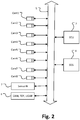
Fig. 2 ein Blockdiagramm zeigt, das schematisch die Konfiguration eines Fahrerassistenzsystems gemäß einem Ausführungsbeispiel der vorliegenden Erfindung darstellt; -
Fig. 3 ein Blockdiagramm ist, das eine beispielhafte Konfiguration eines Steuergeräts zeigt, -
Fig. 4a ein Flussdiagramm eines Prozesses zur Bestimmung des Zustands eines Fahrzeuginsassen durch Analyse von einem oder mehreren Kamerabildern Img1-Img8 gemäß einem Ausführungsbeispiel zeigt; -
Fig. 4b ein Flussdiagramm eines Prozesses zur Bestimmung des Zustands eines Fahrzeuginsassen gemäß einem alternativen Ausführungsbeispiel zeigt, bei dem ein weiteres neuronales Netz vorgesehen ist, um Tiefeninformationen aus Kamerabildern zu gewinnen; -
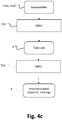
Fig. 4c ein Flussdiagramm eines Prozesses zur Bestimmung des Zustands eines Fahrzeuginsassen gemäß einem alternativen Ausführungsbeispiel zeigt, bei dem durch Korrelationvon Kamerabildern ein 3D-Modell des Fahrzeuginsassen erzeugt wird; -
Fig. 5 beispielhaft einen Prozess des Korrelierens zweier Kamerabilder zeigt, um übereinstimmende Pixel zu identifizieren; -
Fig. 6 einen beispielhaften Prozess des Rekonstruierens der dreidimensionalen Position eines Pixels mittels stereoskopischer Techniken zeigt; -
Fig. 7 eine schematische Abbildung eines neuronalen Netzwerks zeigt; -
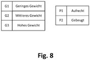
Fig. 8 eine beispielhafte Ausgabe des neuronalen Netzwerks zeigt; -
Fig. 9 ein erfindungsgemässes Sicherheitsgurtsystem zeigt; -
Fig. 10 eine beispielhafte qualitative Heuristik für eine Sicherheitsgurtroutine zeigt; -
Fig. 11 eine Kollisionserkennung gemäß der vorliegenden Erfindung zeigt; -
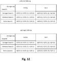
Fig. 12 eine beispielhafte qualitative Heuristik für eine Sicherheitsgurtroutine zeigt, bei der die Gurtparameter unter Berücksichtigung einer prädizierten Verzögerung, die der Fahrer beim Aufprall erfahren wird, angepasst werden; und -
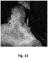
Fig. 13 eine Attention map zeigt, die wichtige Eigenschaften für die Gewichtsklassifizierung mit CNNs visualisiert.
-
Fig. 1 shows a schematic plan view of a vehicle that is equipped with a driver assistance system according to the invention; -
Fig. 2 10 is a block diagram schematically illustrating the configuration of a driver assistance system according to an embodiment of the present invention; -
Fig. 3 FIG. 4 is a block diagram showing an example configuration of a controller; FIG. -
Fig. 4a FIG. 10 shows a flow chart of a process for determining the state of a vehicle occupant by analyzing one or more camera images Img1-Img8 according to an exemplary embodiment; -
Fig. 4b FIG. 10 is a flowchart of a vehicle occupant condition determination process in accordance with an alternate embodiment in which another neural network is provided to obtain depth information from camera images; FIG. -
Fig. 4c FIG. 10 is a flowchart of a vehicle occupant condition determination process in accordance with an alternate embodiment wherein a 3D model of the vehicle occupant is generated by correlating camera images; FIG. -
Fig. 5 exemplarily shows a process of correlating two camera images to identify matching pixels; -
Fig. 6 shows an exemplary process of reconstructing the three-dimensional position of a pixel by means of stereoscopic techniques; -
Fig. 7 shows a schematic illustration of a neural network; -
Fig. 8 shows an exemplary output of the neural network; -
Fig. 9 shows a safety belt system according to the invention; -
Fig. 10 shows an exemplary qualitative heuristic for a seat belt routine; -
Fig. 11 a collision detection according to the present invention; -
Fig. 12 Figure 10 illustrates an example qualitative heuristic for a seat belt routine in which the belt parameters are adjusted in consideration of a predicted deceleration that the driver will experience upon impact; and -
Fig. 13 shows an Attention map that visualizes important properties for weight classification with CNNs.
Die Umfeldsensoren 6 sind dazu ausgelegt, das Umfeld des Fahrzeugs zu erfassen, wobei die Umfeldsensoren 6 am Fahrzeug montiert sind und Objekte oder Zustände im Umfeld des Fahrzeugs erfassen. Hierzu zählen insbesondere Kameras, Radar-Sensoren, Lidar-Sensoren, Ultraschall-Sensoren oder dergleichen. Die erfassten Sensordaten der Umfeldsensoren 6 werden über das Fahrzeugkommunikationsnetzwerk 5 zur Steuereinheit 3 transferiert, in der sie im Hinblick auf das Vorliegen einer kritischen Fahrsituation analysiert werden, wie dies unten mit Bezug zu
Fahrzeugsensoren 7 sind vorzugsweise solche Sensoren, die einen Zustand des Fahrzeugs oder einen Zustand von Fahrzeugteilen erfassen, insbesondere deren Bewegungszustand. Die Sensoren können einen Fahrzeuggeschwindigkeitssensor, einen Gierratensensor, einen Beschleunigungssensor, einen Lenkradwinkelsensor, einen Fahrzeuglastsensor, Temperatursensoren, Drucksensoren und dergleichen umfassen. Beispielsweise können auch Sensoren entlang der Bremsleitung angeordnet sein, um Signale auszugeben, die den Bremsflüssigkeitsdruck an verschiedenen Stellen entlang der hydraulischen Bremsleitung anzeigen. Andere Sensoren in der Nähe des Rades können vorgesehen sein, welche die Radgeschwindigkeit und den Bremsdruck erfassen, der am Rad aufgebracht wird.
Der Prozessor 40 der Steuereinheit 3 ist dazu ausgelegt, von den Fahrzeuginnenraumkameras Cam1-Cam8 kontinuierlich Kamerabilder zu empfangen und einer Bildanalyse zu unterziehen. Der Prozessor 40 der Steuereinheit 3 ist zusätzlich oder alternativ dazu ausgelegt, durch Korrelation von Kamerabildern ein 3D-Modell eines oder mehrerer Fahrzeuginsassen zu erzeugen, wie in
Die Steuereinheit 3 umfasst ferner einen Speicher und eine Eingabe/ Ausgabe-Schnittstelle. Der Speicher kann aus einem oder mehreren nichtflüchtigen computerlesbaren Medien bestehen und umfasst mindestens einen Programmspeicherbereich und einen Datenspeicherbereich. Der Programmspeicherbereich und der Datenspeicherbereich können Kombinationen von verschiedenen Arten von Speicher umfassen, beispielsweise von einem Nur-Lese-Speicher 43 (ROM = Read-only memory) und einem Direktzugriffsspeicher 42 (RAM = Random Access Memory) (z. B. dynamischer RAM ("DRAM"), synchron DRAM ("SDRAM") usw.). Ferner kann die Steuereinheit für autonomes Fahren 18 ein externes Speicherlaufwerk 44, wie beispielsweise ein externes Festplattenlaufwerk (hard disk drive: HDD), ein Flashspeicher-Laufwerk oder ein nicht flüchtiges Festkörperlaufwerk (solid state drive: SSD) umfassen.The
Die Steuereinheit 3 umfasst ferner eine Kommunikationsschnittstelle 45, über welche die Steuereinheit mit dem Fahrzeugkommunikationsnetzwerk (5 in
Neuronale Netze, insbesondere Convolutional Neural Networks (CNNs) erlauben eine Modellierung von komplexen räumlichen Zusammenhängen in zum Beispiel Bilddaten und damit einhergehend, eine datengetriebene Zustandsklassifikation (Gewicht und Haltung eines Fahrzeuginsassen). Durch leistungsfähige Rechner lassen sich sowohl das Fahrzeugverhalten, sowie das Insassenverhalten und der Insassenzustand modellieren um daraus Prädiktionen für Aktionen von passiven Sicherheitssystemen, beispielsweise Gurtstraffern und Gurtsperre, abzuleiten.Neural networks, in particular convolutional neural networks (CNNs), allow a modeling of complex spatial relationships in, for example, image data and, consequently, a data-driven condition classification (weight and attitude of a vehicle occupant). Powerful computers can be used to model vehicle behavior as well as occupant behavior and occupant condition in order to derive predictions for actions of passive safety systems, such as belt tensioners and belt stoppers.
Die Eigenschaften und die Implementierung von neuronalen Netzen sind den entsprechenden Fachkreisen bekannt. Insbesondere wird hier auf die umfangreiche Fachliteratur zu dem Aufbau, den Netztypen, Lernregeln und bekannten Anwendungen von neuronalen Netzen verwiesen.The properties and implementation of neural networks are known to those skilled in the art. In particular, reference is made here to the extensive specialist literature on the structure, network types, learning rules and known applications of neural networks.
Im vorliegenden Fall werden Bilddaten von den Kameras Cam1-Cam8 an das neuronales Netzwerk gesendet werden. Das neuronale Netzwerk kann gefilterte Bilddaten bzw. deren Pixel P1, ..., Pn als Eingabe empfangen und verarbeiten, um einen Fahrerzustand als Ausgabe zu bestimmen, beispielsweise ob sich der Fahrzeuginsasse in einer aufrechten Haltung, Ausgabeneuron P1, oder in einer gebeugten Haltung, Ausgabeneuron P2, befindet und ob der Fahrzeuginsasse ein geringes Gewicht, Ausgabeneuron G1, ein mittleres Gewicht, Ausgabeneuron G2, oder hohes Gewicht, Ausgabeneuron G3, aufweist. Das neuronale Netzwerk kann einen erfassten Fahrzeuginsassen beispielsweise als "Insasse in aufrechter Haltung" oder "Insasse in gebeugter Haltung" bzw. als "Insasse mit geringem Gewicht", "Insasse mit mittlerem Gewicht" oder "Insasse mit hohem Gewicht" klassifizieren.In the present case, image data from the cameras Cam1-Cam8 will be sent to the neural network. The neural network may receive and process filtered image data or its pixels P1, ..., Pn as input to determine a driver condition as output, for example, whether the vehicle occupant is in an upright posture, output neuron P1, or in a stooped posture, Output neuron P2, and whether the vehicle occupant has a low weight, output neuron G1, an average weight, output neuron G2, or high weight, output neuron G3. For example, the neural network may classify a detected vehicle occupant as an "upright occupant" or "a stooped-in occupant," or "a light-weight occupant," an "intermediate-weight occupant," or a "high-weight occupant."
Das neuronale Netzwerkmodul kann ein neuronales Netzwerk beinhalten, das gemäß einem Mehrebenen- (oder "tiefen") Modell konstruiert wurde. Ein neuronales Mehrebenen-Netzwerkmodell kann eine Eingabeebene, eine Vielzahl von verborgenen Ebenen und eine Ausgabeebene beinhalten. Ein neuronales Mehrebenen-Netzwerkmodell kann auch eine Verlustebene beinhalten. Für die Klassifizierung von Sensordaten (z. B. ein Kamerabild) werden Werte in den Sensordaten (z. B. Pixelwerte) Eingangsknoten zugewiesen und dann durch die Vielzahl von verborgenen Ebenen des neuronalen Netzwerks eingespeist. Die Vielzahl von verborgenen Ebenen kann eine Reihe von nichtlinearen Transformationen durchführen. Am Ende der Transformationen ergibt ein Ausgangsknoten einen Wert, der der Klasse (z. B. "aufrecht" oder "gebeugt") entspricht, die von dem neuronalen Netzwerk gefolgert wird.The neural network module may include a neural network constructed according to a multi-level (or "deep") model. A neural multi-level network model may include an input level, a plurality of hidden levels, and an output level. A neural multi-level network model may also include a loss level. For the classification of sensor data (eg, a camera image), values in the sensor data (eg, pixel values) are assigned to input nodes and then fed through the plurality of hidden levels of the neural network. The multitude of hidden layers can perform a series of nonlinear transformations. At the end of the transformations, an output node gives a value corresponding to the class (eg, "upright" or "bowed") that is inferred from the neural network.
Das neuronale Netz wird eingerichtet ("trainiert"), so dass es für bestimmte bekannte Eingangswerte erwartete Antworten erzeugt. Ist ein derartiges neuronales Netz einmal eingerichtet und sind seine Parameter eingestellt, so wird das Netz regelmäßig im Anwendungsfall als eine Art Black-Box verwendet, welche auch für unbekannte Eingangswerte zugehörige und passende Ausgangswerte erzeugt.The neural network is set up ("trained") to produce expected responses for certain known input values. Once such a neural network has been set up and its parameters are set, the network is regularly used in the application as a kind of black box which also generates associated and appropriate output values for unknown input values.
Auf diese Weise kann das neuronale Netzwerk trainiert werden, um auf Grundlage von Kamerabildern zwischen gewünschten Klassifizierungen, wie z. B. "Insasse in aufrechter Haltung" oder "Insasse in gebeugter Haltung", "Insasse mit geringem Gewicht", "Insasse mit mittlerem Gewicht" und "Insasse mit hohem Gewicht" zu unterscheiden.In this way, the neural network can be trained to determine, based on camera images, between desired classifications, e.g. For example, "occupant in upright posture" or "inmate in stooped posture", "inmate with low weight", "occupant with medium weight" and "inmate with high weight".
Die hier gegebenen Zustandsklassen sind schematisch und beispielhaft. Zusätzlich oder alternativ können andere Zustände definiert werden und es wäre auch denkbar, von einem Kamerabild der Innenraumkameras Cam1-Cam8 oder einem 3D-Modell des Fahrzeuginsassen Rückschlüsse auf das Verhalten des Fahrzeuginsassen zu ziehen. Beispielsweise könnte aus den Bilddaten eine Blickrichtung, eine Handgelenkpose oder dergleichen abgeleitet und mittels eins neuronalen Netzwerks klassifiziert werden.The condition classes given here are schematic and exemplary. Additionally or alternatively, other states can be defined and it would also be conceivable to draw conclusions about the behavior of the vehicle occupant from a camera image of the interior cameras Cam1-Cam8 or a 3D model of the vehicle occupant. For example, a gaze direction, a wrist pose or the like could be derived from the image data and classified by means of a neural network.
Erfindungsgemäß werden die Gurtstraffer GSPO und GSPU in Abhängigkeit von der Fahrsituation und von dem Ergebnisses der Zustandsklassifikation des Fahrzeuginsassen von der Steuereinheit (3 in
Ziel ist es, den Insassen mit entsprechender Zugrichtung und Zugkraft der Gurtstraffer GST und unter Einsatz der Gurtsperre GSP vor dem Aufprall in eine optimale Position zu bringen. Die optimale Position ist hierbei definiert als die Position, in der das passive Sicherheitssystem (Airbag, etc.) den optimalen Wirkungsgrad einnimmt. Es wird davon ausgegangen, dass dies der aufrichten Lage des Insassen entspricht, wobei der Gurt optimal gestrafft ist. Nimmt beispielsweise ein Beifahrer eine gebeugte Haltung ein, so begibt er sich außerhalb der Position, in der ein optimaler Schutz durch den Airbag gewährleistet ist und seine Position kann durch Straffung des Sicherheitsgurtes korrigiert werden.The aim is to bring the occupants with the appropriate tension and tension of the belt tensioner GST and using the belt lock GSP before the impact in an optimal position. The optimum position is defined here as the position in which the passive safety system (airbag, etc.) assumes the optimum efficiency. It is assumed that this corresponds to the upright position of the occupant, whereby the belt is optimally tightened. For example, if a passenger takes a stooped posture, he moves outside the position where optimal protection is provided is ensured by the airbag and its position can be corrected by tightening the seat belt.
Das Erreichen der optimalen Position wird durch die Gurtsperre GSP beschleunigt, da so die einzuziehende Gurtlänge zwischen oberem Gurtstraffer GSTO und der Gurtsperre GSP ausschlaggebend ist und nicht mehr die gesamte Gurtlänge von Gurtstraffer zu Gurtstraffer eingezogen werden muss.Achieving the optimum position is accelerated by the belt lock GSP, since so the recovering belt length between the upper belt tensioner GSTO and the belt lock GSP is crucial and no longer the entire belt length of belt tensioner to belt tensioner must be retracted.
Ein Gurtstraffer kann beispielsweise als Elektromotor ausgeführt sein. In diesem Fall kann, um die erhöhte Gurtspannkraft zu erzeugen, dem Elektromotor als Gurtstraffer eine Spannung, die oberhalb der Nennspannung des Elektromotors liegt, zugeführt werden. Alternativ dazu kann eine Getriebeübersetzung des Elektromotors verändert werden. In einer weiteren alternativen Ausführungsform kann die erhöhte Gurtspannkraft mittels eines mechanischen oder elektrischen Energiespeichers erzeugt werden.A belt tensioner may for example be designed as an electric motor. In this case, in order to produce the increased belt tensioning force, the electric motor as belt tensioner may be supplied with a voltage which is above the rated voltage of the electric motor. Alternatively, a gear ratio of the electric motor can be changed. In a further alternative embodiment, the increased belt tensioning force can be generated by means of a mechanical or electrical energy store.
Erfindungsgemäß ist die Steuereinheit dazu ausgelegt, bei Erkennen einer kritischen Fahrsituation, beispielsweise bei einem prädizierten Aufprall oder einer prädizierten Notbremsung, die durch einen Aufprall bzw. eine Betätigung des Bremspedals und Detektion eines Objektes mit vorausschauender Sensorik oder auch durch den Bremsassistenten ausgelöst werden kann, die Gurtstraffer im Sicherheitsgurtsystem 4 zu aktivieren und gegebene Kräfte anzusteuern.According to the invention, the control unit is designed, upon detection of a critical driving situation, for example during a predicated impact or a predicated emergency braking, which can be triggered by an impact or actuation of the brake pedal and detection of an object with predictive sensor technology or by the brake assist, the To activate the belt tensioner in the
Die Steuereinheit 3 ist ferner so ausgelegt, dass der durch die Bildverarbeitung ermittelte Zustand eines Fahrzeuginsassen in die Steuerung der Gurtstraffer mit einfließt. So kann beispielsweise das Kraftniveau bei schwereren Insassen auf ein höheres Niveau angehoben werden und bei leichteren Insassen entsprechend abgesenkt werden, um so neben einer optimalen Sicherung einen maximalen Komfort des Insassen zu gewährleisten.The
Für den angepassten Einsatz der Gurtstraffer wird beispielsweise eine Heuristik vorgesehen, die ausgehend von Haltung und Gewicht des Insassen sowie von einem Fahrzeugzustand/einer Fahrsituation eine entsprechende Gurtstraffroutine definiert. Zusätzlich oder alternativ kann diese datengetrieben gelernt und so optimiert werden.For the adjusted use of the belt tensioner, for example, a heuristic is provided, the basis of attitude and weight of the occupant and a Vehicle state / a driving situation defines a corresponding belt tensioning routine. Additionally or alternatively, this can be learned data-driven and optimized.
Wie aus der Tabelle in
In einer bevorzugten Ausführungsform der vorliegenden Erfindung werden die Gurtparameter ferner unter Berücksichtigung einer prädizierten Verzögerung, die der Fahrer bei einem Aufprall oder Bremsvorgang erfahren wird, angepasst. Um die Verzögerung vorherzusagen wird zunächst eine Kollisionsprädiktion durchgeführt. Ziel ist beispielsweise die Schätzung des "point of no return", ab dem eine Kollision unvermeidbar geworden ist und ein Aufprall ansteht. Anhand dieses "point of no return" und der sich ergebenden Aufprallgeschwindigkeit werden dann die Verzögerungsstrategie und die sich ergebenden Verzögerungen abgeleitet.In a preferred embodiment of the present invention, the belt parameters are further adjusted in consideration of a predicted deceleration experienced by the driver in an impact or braking event. To predict the delay, a collision prediction is first performed. The aim is, for example, the estimation of the "point of no return", from which a collision has become unavoidable and an impact is pending. Based on this "point of no return" and the resulting impact velocity, then the delay strategy and the resulting delays are derived.
Die obere Tabelle in
Die untere Tabelle in
Die Verwendung eines neuronalen Netzwerks zur Bestimmung des Fahrerzustands ermöglicht beispielsweise eine Bestimmung einer sog. "Attention map", welche aufzeigt, welche Bereiche eines Fahrzeuginsassen für die Erkennung des Insassenzustands besonders relevant sind.For example, the use of a neural network to determine the driver's state enables a so-called "attention map" to be determined, which shows which areas of a vehicle occupant are particularly relevant for the detection of the occupant condition.
- 11
- Fahrzeugvehicle
- 22
- FahrzeuginnenraumVehicle interior
- 33
- Steuereinheitcontrol unit
- 44
- Sicherheitsgurtsystemseat belt system
- 55
- Kommunikationssystemcommunication system
- 66
- Umfeldsensorenenvironmental sensors
- 77
- Fahrzeugsensorenvehicle sensors
- 88th
- Neuronales NetzwerkmodulNeural network module
- Cam1-Cam8Cam1-CAM8
- InnenraumkameraInterior camera
- Img1-Img8Img1-img8
- Kamerabildercamera images
- GSPOGSPO
- oberer GurtstrafferUpper belt tensioner
- GSPUGSPU
- unterer Gurtstrafferlower belt tensioner
- GSPGSP
- GurtsperreGurtsperre
- Pixpix
- Pixel des FahrzeuginsassenPixels of the vehicle occupant
- Insin the
- Fahrzeuginsasse im FahrzeuginnenraumVehicle occupant in the vehicle interior
- InsEINSE
- Element des Fahrzeuginsassen im BildElement of the vehicle occupant in the picture
- Mod3DMod3D
- 3D-Modell des Fahrzeuginnenraums3D model of the vehicle interior
- Mod3DaMod3Da
- rekonstruiertes 3D-Modell des Fahrzeuginnenraumsreconstructed 3D model of the vehicle interior
- Mod3DbMod3Db
- vordefiniertes 3D-Modell des Fahrzeuginnenraumspredefined 3D model of the vehicle interior
- P1, P2P1, P2
- Pixel im KamerabildPixels in the camera image
- P3DP3D
- rekonstruierte dreidimensionale Positionreconstructed three-dimensional position
- OS1, OS2OS1, OS2
- Optische Strahlen bezüglich erster und zweiter KameraOptical beams with respect to first and second camera
- S1-S4S1-S4
- Sitzeseats
- ZZ
- Insassenzustandoccupant condition
- VZVZ
- prädizierte Verzögerungpredicted delay
Claims (10)
Applications Claiming Priority (1)
| Application Number | Priority Date | Filing Date | Title |
|---|---|---|---|
| DE102018207977.3A DE102018207977B4 (en) | 2018-05-22 | 2018-05-22 | Interior monitoring for seat belt adjustment |
Publications (1)
| Publication Number | Publication Date |
|---|---|
| EP3572290A1 true EP3572290A1 (en) | 2019-11-27 |
Family
ID=66439918
Family Applications (1)
| Application Number | Title | Priority Date | Filing Date |
|---|---|---|---|
| EP19172871.6A Withdrawn EP3572290A1 (en) | 2018-05-22 | 2019-05-07 | Internal monitoring for safety belt adjustment |
Country Status (4)
| Country | Link |
|---|---|
| US (1) | US20190359169A1 (en) |
| EP (1) | EP3572290A1 (en) |
| CN (1) | CN110509881A (en) |
| DE (1) | DE102018207977B4 (en) |
Cited By (1)
| Publication number | Priority date | Publication date | Assignee | Title |
|---|---|---|---|---|
| WO2022033891A1 (en) * | 2020-08-14 | 2022-02-17 | Continental Automotive Gmbh | Method for determining the posture of a driver |
Families Citing this family (15)
| Publication number | Priority date | Publication date | Assignee | Title |
|---|---|---|---|---|
| EP3666564B1 (en) * | 2018-12-12 | 2023-10-11 | Ningbo Geely Automobile Research & Development Co., Ltd. | A system and method for estimating climate needs |
| CN114144814A (en) * | 2019-07-09 | 2022-03-04 | 贾迪安光学技术有限公司 | System, device and method for measuring the mass of an object in a vehicle |
| US10803334B1 (en) * | 2019-10-18 | 2020-10-13 | Alpine Electronics of Silicon Valley, Inc. | Detection of unsafe cabin conditions in autonomous vehicles |
| CN111669548B (en) * | 2020-06-04 | 2021-11-26 | 赛特斯信息科技股份有限公司 | Method for realizing safety supervision and treatment aiming at pole climbing operation of power distribution network |
| DE102020210766A1 (en) | 2020-08-25 | 2022-03-03 | Brose Fahrzeugteile Se & Co. Kommanditgesellschaft, Bamberg | Method for operating a motor vehicle having an interior |
| DE102020210768A1 (en) | 2020-08-25 | 2022-03-03 | Brose Fahrzeugteile Se & Co. Kommanditgesellschaft, Bamberg | Method for operating a motor vehicle having an interior |
| US11807181B2 (en) | 2020-10-27 | 2023-11-07 | GM Global Technology Operations LLC | Vision-based airbag enablement |
| CN112541413B (en) * | 2020-11-30 | 2024-02-23 | 阿拉善盟特种设备检验所 | Dangerous behavior detection method and system for forklift driver real operation assessment and coaching |
| DE102021200306A1 (en) | 2021-01-14 | 2022-07-14 | Volkswagen Aktiengesellschaft | Method for analyzing a person's posture and/or movement |
| US11465583B2 (en) * | 2021-02-04 | 2022-10-11 | Toyota Research Institute, Inc. | Producing a force to be applied to a seatbelt in response to a deceleration of a vehicle |
| KR102537668B1 (en) | 2021-03-26 | 2023-05-30 | 현대모비스 주식회사 | Apparatus for protecting passenger on vehicle and control method thereof |
| DE102021002923B3 (en) | 2021-06-03 | 2022-12-15 | Volker Mittelstaedt | Method of operating a seat belt device with a reversible belt tensioner |
| DE102022203558A1 (en) | 2022-04-08 | 2023-10-12 | Zf Friedrichshafen Ag | Determining a response to a vehicle occupant pose |
| DE102022001928A1 (en) | 2022-05-30 | 2023-12-14 | Volker Mittelstaedt | Method for operating a seat belt device with reversible belt tensioners during automated or highly automated driving |
| DE102022212662A1 (en) | 2022-09-27 | 2024-03-28 | Continental Automotive Technologies GmbH | Method and device for needs-based control of an occupant protection device |
Citations (7)
| Publication number | Priority date | Publication date | Assignee | Title |
|---|---|---|---|---|
| DE4406906A1 (en) | 1994-03-03 | 1995-09-07 | Docter Optik Wetzlar Gmbh | Inside room monitoring device |
| US6728616B1 (en) | 2000-10-20 | 2004-04-27 | Joseph A. Tabe | Smart seatbelt control system |
| DE102006061427A1 (en) | 2006-12-23 | 2008-06-26 | Daimler Ag | Method and belt tightening system for restraining occupants of a vehicle in an impact on an obstacle |
| US20080294315A1 (en) * | 1995-06-07 | 2008-11-27 | Intelligent Technologies International, Inc. | System and Method for Controlling Vehicle Headlights |
| US20140093133A1 (en) * | 2009-03-02 | 2014-04-03 | Flir Systems, Inc. | Systems and methods for monitoring vehicle occupants |
| CN104802743A (en) * | 2014-01-28 | 2015-07-29 | 上海汽车集团股份有限公司 | Air bag unfolding control method and device |
| US20160078306A1 (en) * | 2014-09-15 | 2016-03-17 | Xerox Corporation | System and method for detecting seat belt violations from front view vehicle images |
Family Cites Families (26)
| Publication number | Priority date | Publication date | Assignee | Title |
|---|---|---|---|---|
| US6735506B2 (en) * | 1992-05-05 | 2004-05-11 | Automotive Technologies International, Inc. | Telematics system |
| US7164117B2 (en) * | 1992-05-05 | 2007-01-16 | Automotive Technologies International, Inc. | Vehicular restraint system control system and method using multiple optical imagers |
| US20080147280A1 (en) * | 1995-06-07 | 2008-06-19 | Automotive Technologies International, Inc. | Method and apparatus for sensing a rollover |
| US5983147A (en) * | 1997-02-06 | 1999-11-09 | Sandia Corporation | Video occupant detection and classification |
| JP3865182B2 (en) * | 1998-12-25 | 2007-01-10 | タカタ株式会社 | Seat belt system |
| DE19932520A1 (en) * | 1999-07-12 | 2001-02-01 | Hirschmann Austria Gmbh Rankwe | Device for controlling a security system |
| JP4667549B2 (en) * | 1999-09-10 | 2011-04-13 | オートリブ株式会社 | Seat belt device |
| DE10005010C2 (en) * | 2000-02-04 | 2002-11-21 | Daimler Chrysler Ag | Method and safety restraint for restraining an occupant in a vehicle seat |
| US6392550B1 (en) * | 2000-11-17 | 2002-05-21 | Ford Global Technologies, Inc. | Method and apparatus for monitoring driver alertness |
| DE10133759C2 (en) * | 2001-07-11 | 2003-07-24 | Daimler Chrysler Ag | Belt guide recognition with image processing system in the vehicle |
| EP1586490B1 (en) * | 2003-01-24 | 2008-06-18 | HONDA MOTOR CO., Ltd. | Travel safety device for motor vehicle |
| EP1475274B1 (en) * | 2003-05-06 | 2011-08-31 | Mitsubishi Electric Information Technology Centre Europe B.V. | Seat occupant monitoring system and method |
| JP2005263176A (en) * | 2004-03-22 | 2005-09-29 | Denso Corp | Seat belt device |
| US7519461B2 (en) * | 2005-11-02 | 2009-04-14 | Lear Corporation | Discriminate input system for decision algorithm |
| JP2007218626A (en) * | 2006-02-14 | 2007-08-30 | Takata Corp | Object detecting system, operation device control system, vehicle |
| US20070213886A1 (en) * | 2006-03-10 | 2007-09-13 | Yilu Zhang | Method and system for driver handling skill recognition through driver's steering behavior |
| DE102006040244B3 (en) * | 2006-08-28 | 2007-08-30 | Robert Bosch Gmbh | Device for seat occupation recognition has several markings on safety belt at predetermined distance from each other, and has evaluation and control unit to evaluate images recorded by monocamera |
| DE102009000160B4 (en) * | 2009-01-13 | 2019-06-13 | Robert Bosch Gmbh | Method and control device for controlling personal protective equipment for a vehicle |
| CN102567743A (en) * | 2011-12-20 | 2012-07-11 | 东南大学 | Automatic identification method of driver gestures based on video images |
| US10293836B2 (en) * | 2013-10-08 | 2019-05-21 | Trw Automotive Gmbh | Vehicle assistant system and vehicle |
| US9598037B2 (en) * | 2014-09-03 | 2017-03-21 | GM Global Technology Operations LLC | Sensor based occupant protection system |
| DE102014223618B4 (en) | 2014-11-19 | 2019-12-19 | Robert Bosch Gmbh | Method for operating a safety device of a motor vehicle |
| JP2018512334A (en) * | 2015-04-10 | 2018-05-17 | ローベルト ボツシユ ゲゼルシヤフト ミツト ベシユレンクテル ハフツングRobert Bosch Gmbh | Detection of occupant dimensions and posture by in-vehicle camera |
| DE102016011242A1 (en) * | 2016-09-17 | 2017-04-13 | Daimler Ag | A method of monitoring a condition of at least one occupant of a vehicle |
| CN107180438B (en) * | 2017-04-26 | 2020-02-07 | 清华大学 | Method for estimating size and weight of yak and corresponding portable computer device |
| CN107330439B (en) * | 2017-07-14 | 2022-11-04 | 腾讯科技(深圳)有限公司 | Method for determining posture of object in image, client and server |
-
2018
- 2018-05-22 DE DE102018207977.3A patent/DE102018207977B4/en active Active
-
2019
- 2019-05-07 EP EP19172871.6A patent/EP3572290A1/en not_active Withdrawn
- 2019-05-17 CN CN201910410396.XA patent/CN110509881A/en active Pending
- 2019-05-22 US US16/419,476 patent/US20190359169A1/en not_active Abandoned
Patent Citations (7)
| Publication number | Priority date | Publication date | Assignee | Title |
|---|---|---|---|---|
| DE4406906A1 (en) | 1994-03-03 | 1995-09-07 | Docter Optik Wetzlar Gmbh | Inside room monitoring device |
| US20080294315A1 (en) * | 1995-06-07 | 2008-11-27 | Intelligent Technologies International, Inc. | System and Method for Controlling Vehicle Headlights |
| US6728616B1 (en) | 2000-10-20 | 2004-04-27 | Joseph A. Tabe | Smart seatbelt control system |
| DE102006061427A1 (en) | 2006-12-23 | 2008-06-26 | Daimler Ag | Method and belt tightening system for restraining occupants of a vehicle in an impact on an obstacle |
| US20140093133A1 (en) * | 2009-03-02 | 2014-04-03 | Flir Systems, Inc. | Systems and methods for monitoring vehicle occupants |
| CN104802743A (en) * | 2014-01-28 | 2015-07-29 | 上海汽车集团股份有限公司 | Air bag unfolding control method and device |
| US20160078306A1 (en) * | 2014-09-15 | 2016-03-17 | Xerox Corporation | System and method for detecting seat belt violations from front view vehicle images |
Non-Patent Citations (1)
| Title |
|---|
| OLIVIER FAUGERAS ET AL.: "Real-time correlation-based stereo: algorithm, implementations and applications", RR-2013, INRIA, 1993 |
Cited By (2)
| Publication number | Priority date | Publication date | Assignee | Title |
|---|---|---|---|---|
| WO2022033891A1 (en) * | 2020-08-14 | 2022-02-17 | Continental Automotive Gmbh | Method for determining the posture of a driver |
| FR3113390A1 (en) * | 2020-08-14 | 2022-02-18 | Continental Automotive | Method for determining the posture of a driver |
Also Published As
| Publication number | Publication date |
|---|---|
| DE102018207977B4 (en) | 2023-11-02 |
| CN110509881A (en) | 2019-11-29 |
| US20190359169A1 (en) | 2019-11-28 |
| DE102018207977A1 (en) | 2019-11-28 |
Similar Documents
| Publication | Publication Date | Title |
|---|---|---|
| DE102018207977B4 (en) | Interior monitoring for seat belt adjustment | |
| DE102004046360B4 (en) | Motor vehicle with a preventive protection system | |
| EP1387183B1 (en) | Method and apparatus for determining an unavoidable collision event | |
| DE19736840B4 (en) | Method for situation-dependent triggering of a restraint system and restraint system | |
| EP1404539B1 (en) | Method and device for influencing at least one parameter on a vehicle | |
| DE102005013164B4 (en) | Method and device for controlling a passive restraint system | |
| DE102006047131A1 (en) | Method for automatically controlling a vehicle | |
| DE102017201822A1 (en) | Method and device for controlling a vehicle seat | |
| WO2006015747A1 (en) | Motor vehicle comprising a preventive protective system | |
| EP2054274A1 (en) | Method and device for the actuation of personal protection means | |
| DE102017216083B4 (en) | Impact absorbing device and method for a vehicle | |
| DE10202908B4 (en) | Method and arrangement for determining a detection range of a pre-crash sensor system | |
| DE102008043637A1 (en) | Protection system e.g. active occupant protection system, activating and/or controlling method for use in motor vehicle, involves evaluating ambient situation and/or actual driving condition of vehicle to detect secondary crash | |
| DE102016209704A1 (en) | Method for controlling a passenger protection device of a vehicle and control unit | |
| EP1522042A1 (en) | Method for detecting a person in a space | |
| DE10335601B4 (en) | Object classification method using a 3D model database | |
| DE102016210491A1 (en) | Method for controlling a passenger protection device of a vehicle and control unit | |
| EP3700784A1 (en) | Device and method for adaptive vehicle control | |
| DE102014010200A1 (en) | Method and device for operating a vehicle | |
| DE102009020074A1 (en) | Vehicle passenger protection system controlling method for e.g. air bag, involves comparing course of characteristic and/or criterion with reference curve by algorithm model that is selected depending on collision specification | |
| WO2017174409A1 (en) | Method for changing the forward movement of an occupant of a vehicle when braking the vehicle, and controller | |
| DE102009000080B4 (en) | Method and control unit for detecting a driving state of a vehicle | |
| WO2004026637A1 (en) | Device and method for detection of an object or a person in the interior of a motor vehicle | |
| DE102008003081B4 (en) | Method and device for crash classification for a vehicle safety system | |
| WO2003007244A1 (en) | Detection of the change of position of a vehicle occupant in an image sequence |
Legal Events
| Date | Code | Title | Description |
|---|---|---|---|
| PUAI | Public reference made under article 153(3) epc to a published international application that has entered the european phase |
Free format text: ORIGINAL CODE: 0009012 |
|
| STAA | Information on the status of an ep patent application or granted ep patent |
Free format text: STATUS: THE APPLICATION HAS BEEN PUBLISHED |
|
| AK | Designated contracting states |
Kind code of ref document: A1 Designated state(s): AL AT BE BG CH CY CZ DE DK EE ES FI FR GB GR HR HU IE IS IT LI LT LU LV MC MK MT NL NO PL PT RO RS SE SI SK SM TR |
|
| AX | Request for extension of the european patent |
Extension state: BA ME |
|
| STAA | Information on the status of an ep patent application or granted ep patent |
Free format text: STATUS: REQUEST FOR EXAMINATION WAS MADE |
|
| 17P | Request for examination filed |
Effective date: 20200120 |
|
| STAA | Information on the status of an ep patent application or granted ep patent |
Free format text: STATUS: EXAMINATION IS IN PROGRESS |
|
| STAA | Information on the status of an ep patent application or granted ep patent |
Free format text: STATUS: THE APPLICATION HAS BEEN WITHDRAWN |
|
| 17Q | First examination report despatched |
Effective date: 20210623 |
|
| 18W | Application withdrawn |
Effective date: 20210625 |