EP3572260A1 - Structure of mounting power converter in vehicle - Google Patents
Structure of mounting power converter in vehicle Download PDFInfo
- Publication number
- EP3572260A1 EP3572260A1 EP19171146.4A EP19171146A EP3572260A1 EP 3572260 A1 EP3572260 A1 EP 3572260A1 EP 19171146 A EP19171146 A EP 19171146A EP 3572260 A1 EP3572260 A1 EP 3572260A1
- Authority
- EP
- European Patent Office
- Prior art keywords
- legs
- housing
- casing
- power converter
- motor housing
- Prior art date
- Legal status (The legal status is an assumption and is not a legal conclusion. Google has not performed a legal analysis and makes no representation as to the accuracy of the status listed.)
- Withdrawn
Links
Images


Classifications
-
- B—PERFORMING OPERATIONS; TRANSPORTING
- B60—VEHICLES IN GENERAL
- B60K—ARRANGEMENT OR MOUNTING OF PROPULSION UNITS OR OF TRANSMISSIONS IN VEHICLES; ARRANGEMENT OR MOUNTING OF PLURAL DIVERSE PRIME-MOVERS IN VEHICLES; AUXILIARY DRIVES FOR VEHICLES; INSTRUMENTATION OR DASHBOARDS FOR VEHICLES; ARRANGEMENTS IN CONNECTION WITH COOLING, AIR INTAKE, GAS EXHAUST OR FUEL SUPPLY OF PROPULSION UNITS IN VEHICLES
- B60K6/00—Arrangement or mounting of plural diverse prime-movers for mutual or common propulsion, e.g. hybrid propulsion systems comprising electric motors and internal combustion engines ; Control systems therefor, i.e. systems controlling two or more prime movers, or controlling one of these prime movers and any of the transmission, drive or drive units Informative references: mechanical gearings with secondary electric drive F16H3/72; arrangements for handling mechanical energy structurally associated with the dynamo-electric machine H02K7/00; machines comprising structurally interrelated motor and generator parts H02K51/00; dynamo-electric machines not otherwise provided for in H02K see H02K99/00
- B60K6/20—Arrangement or mounting of plural diverse prime-movers for mutual or common propulsion, e.g. hybrid propulsion systems comprising electric motors and internal combustion engines ; Control systems therefor, i.e. systems controlling two or more prime movers, or controlling one of these prime movers and any of the transmission, drive or drive units Informative references: mechanical gearings with secondary electric drive F16H3/72; arrangements for handling mechanical energy structurally associated with the dynamo-electric machine H02K7/00; machines comprising structurally interrelated motor and generator parts H02K51/00; dynamo-electric machines not otherwise provided for in H02K see H02K99/00 the prime-movers consisting of electric motors and internal combustion engines, e.g. HEVs
- B60K6/22—Arrangement or mounting of plural diverse prime-movers for mutual or common propulsion, e.g. hybrid propulsion systems comprising electric motors and internal combustion engines ; Control systems therefor, i.e. systems controlling two or more prime movers, or controlling one of these prime movers and any of the transmission, drive or drive units Informative references: mechanical gearings with secondary electric drive F16H3/72; arrangements for handling mechanical energy structurally associated with the dynamo-electric machine H02K7/00; machines comprising structurally interrelated motor and generator parts H02K51/00; dynamo-electric machines not otherwise provided for in H02K see H02K99/00 the prime-movers consisting of electric motors and internal combustion engines, e.g. HEVs characterised by apparatus, components or means specially adapted for HEVs
- B60K6/40—Arrangement or mounting of plural diverse prime-movers for mutual or common propulsion, e.g. hybrid propulsion systems comprising electric motors and internal combustion engines ; Control systems therefor, i.e. systems controlling two or more prime movers, or controlling one of these prime movers and any of the transmission, drive or drive units Informative references: mechanical gearings with secondary electric drive F16H3/72; arrangements for handling mechanical energy structurally associated with the dynamo-electric machine H02K7/00; machines comprising structurally interrelated motor and generator parts H02K51/00; dynamo-electric machines not otherwise provided for in H02K see H02K99/00 the prime-movers consisting of electric motors and internal combustion engines, e.g. HEVs characterised by apparatus, components or means specially adapted for HEVs characterised by the assembly or relative disposition of components
- B60K6/405—Housings
-
- H—ELECTRICITY
- H02—GENERATION; CONVERSION OR DISTRIBUTION OF ELECTRIC POWER
- H02K—DYNAMO-ELECTRIC MACHINES
- H02K7/00—Arrangements for handling mechanical energy structurally associated with dynamo-electric machines, e.g. structural association with mechanical driving motors or auxiliary dynamo-electric machines
- H02K7/003—Couplings; Details of shafts
-
- B—PERFORMING OPERATIONS; TRANSPORTING
- B60—VEHICLES IN GENERAL
- B60L—PROPULSION OF ELECTRICALLY-PROPELLED VEHICLES; SUPPLYING ELECTRIC POWER FOR AUXILIARY EQUIPMENT OF ELECTRICALLY-PROPELLED VEHICLES; ELECTRODYNAMIC BRAKE SYSTEMS FOR VEHICLES IN GENERAL; MAGNETIC SUSPENSION OR LEVITATION FOR VEHICLES; MONITORING OPERATING VARIABLES OF ELECTRICALLY-PROPELLED VEHICLES; ELECTRIC SAFETY DEVICES FOR ELECTRICALLY-PROPELLED VEHICLES
- B60L15/00—Methods, circuits, or devices for controlling the traction-motor speed of electrically-propelled vehicles
- B60L15/007—Physical arrangements or structures of drive train converters specially adapted for the propulsion motors of electric vehicles
-
- B—PERFORMING OPERATIONS; TRANSPORTING
- B60—VEHICLES IN GENERAL
- B60K—ARRANGEMENT OR MOUNTING OF PROPULSION UNITS OR OF TRANSMISSIONS IN VEHICLES; ARRANGEMENT OR MOUNTING OF PLURAL DIVERSE PRIME-MOVERS IN VEHICLES; AUXILIARY DRIVES FOR VEHICLES; INSTRUMENTATION OR DASHBOARDS FOR VEHICLES; ARRANGEMENTS IN CONNECTION WITH COOLING, AIR INTAKE, GAS EXHAUST OR FUEL SUPPLY OF PROPULSION UNITS IN VEHICLES
- B60K1/00—Arrangement or mounting of electrical propulsion units
- B60K1/04—Arrangement or mounting of electrical propulsion units of the electric storage means for propulsion
-
- B—PERFORMING OPERATIONS; TRANSPORTING
- B60—VEHICLES IN GENERAL
- B60L—PROPULSION OF ELECTRICALLY-PROPELLED VEHICLES; SUPPLYING ELECTRIC POWER FOR AUXILIARY EQUIPMENT OF ELECTRICALLY-PROPELLED VEHICLES; ELECTRODYNAMIC BRAKE SYSTEMS FOR VEHICLES IN GENERAL; MAGNETIC SUSPENSION OR LEVITATION FOR VEHICLES; MONITORING OPERATING VARIABLES OF ELECTRICALLY-PROPELLED VEHICLES; ELECTRIC SAFETY DEVICES FOR ELECTRICALLY-PROPELLED VEHICLES
- B60L53/00—Methods of charging batteries, specially adapted for electric vehicles; Charging stations or on-board charging equipment therefor; Exchange of energy storage elements in electric vehicles
- B60L53/20—Methods of charging batteries, specially adapted for electric vehicles; Charging stations or on-board charging equipment therefor; Exchange of energy storage elements in electric vehicles characterised by converters located in the vehicle
-
- B—PERFORMING OPERATIONS; TRANSPORTING
- B60—VEHICLES IN GENERAL
- B60R—VEHICLES, VEHICLE FITTINGS, OR VEHICLE PARTS, NOT OTHERWISE PROVIDED FOR
- B60R11/00—Arrangements for holding or mounting articles, not otherwise provided for
-
- B—PERFORMING OPERATIONS; TRANSPORTING
- B60—VEHICLES IN GENERAL
- B60R—VEHICLES, VEHICLE FITTINGS, OR VEHICLE PARTS, NOT OTHERWISE PROVIDED FOR
- B60R16/00—Electric or fluid circuits specially adapted for vehicles and not otherwise provided for; Arrangement of elements of electric or fluid circuits specially adapted for vehicles and not otherwise provided for
- B60R16/02—Electric or fluid circuits specially adapted for vehicles and not otherwise provided for; Arrangement of elements of electric or fluid circuits specially adapted for vehicles and not otherwise provided for electric constitutive elements
- B60R16/03—Electric or fluid circuits specially adapted for vehicles and not otherwise provided for; Arrangement of elements of electric or fluid circuits specially adapted for vehicles and not otherwise provided for electric constitutive elements for supply of electrical power to vehicle subsystems or for
-
- H—ELECTRICITY
- H02—GENERATION; CONVERSION OR DISTRIBUTION OF ELECTRIC POWER
- H02M—APPARATUS FOR CONVERSION BETWEEN AC AND AC, BETWEEN AC AND DC, OR BETWEEN DC AND DC, AND FOR USE WITH MAINS OR SIMILAR POWER SUPPLY SYSTEMS; CONVERSION OF DC OR AC INPUT POWER INTO SURGE OUTPUT POWER; CONTROL OR REGULATION THEREOF
- H02M1/00—Details of apparatus for conversion
-
- H—ELECTRICITY
- H02—GENERATION; CONVERSION OR DISTRIBUTION OF ELECTRIC POWER
- H02M—APPARATUS FOR CONVERSION BETWEEN AC AND AC, BETWEEN AC AND DC, OR BETWEEN DC AND DC, AND FOR USE WITH MAINS OR SIMILAR POWER SUPPLY SYSTEMS; CONVERSION OF DC OR AC INPUT POWER INTO SURGE OUTPUT POWER; CONTROL OR REGULATION THEREOF
- H02M7/00—Conversion of ac power input into dc power output; Conversion of dc power input into ac power output
- H02M7/003—Constructional details, e.g. physical layout, assembly, wiring or busbar connections
-
- H—ELECTRICITY
- H02—GENERATION; CONVERSION OR DISTRIBUTION OF ELECTRIC POWER
- H02M—APPARATUS FOR CONVERSION BETWEEN AC AND AC, BETWEEN AC AND DC, OR BETWEEN DC AND DC, AND FOR USE WITH MAINS OR SIMILAR POWER SUPPLY SYSTEMS; CONVERSION OF DC OR AC INPUT POWER INTO SURGE OUTPUT POWER; CONTROL OR REGULATION THEREOF
- H02M7/00—Conversion of ac power input into dc power output; Conversion of dc power input into ac power output
- H02M7/42—Conversion of dc power input into ac power output without possibility of reversal
- H02M7/44—Conversion of dc power input into ac power output without possibility of reversal by static converters
-
- B—PERFORMING OPERATIONS; TRANSPORTING
- B60—VEHICLES IN GENERAL
- B60R—VEHICLES, VEHICLE FITTINGS, OR VEHICLE PARTS, NOT OTHERWISE PROVIDED FOR
- B60R11/00—Arrangements for holding or mounting articles, not otherwise provided for
- B60R2011/0001—Arrangements for holding or mounting articles, not otherwise provided for characterised by position
- B60R2011/0003—Arrangements for holding or mounting articles, not otherwise provided for characterised by position inside the vehicle
- B60R2011/0038—Engine compartment
-
- B—PERFORMING OPERATIONS; TRANSPORTING
- B60—VEHICLES IN GENERAL
- B60Y—INDEXING SCHEME RELATING TO ASPECTS CROSS-CUTTING VEHICLE TECHNOLOGY
- B60Y2200/00—Type of vehicle
- B60Y2200/90—Vehicles comprising electric prime movers
- B60Y2200/91—Electric vehicles
-
- B—PERFORMING OPERATIONS; TRANSPORTING
- B60—VEHICLES IN GENERAL
- B60Y—INDEXING SCHEME RELATING TO ASPECTS CROSS-CUTTING VEHICLE TECHNOLOGY
- B60Y2200/00—Type of vehicle
- B60Y2200/90—Vehicles comprising electric prime movers
- B60Y2200/92—Hybrid vehicles
-
- B—PERFORMING OPERATIONS; TRANSPORTING
- B60—VEHICLES IN GENERAL
- B60Y—INDEXING SCHEME RELATING TO ASPECTS CROSS-CUTTING VEHICLE TECHNOLOGY
- B60Y2306/00—Other features of vehicle sub-units
- B60Y2306/01—Reducing damages in case of crash, e.g. by improving battery protection
-
- Y—GENERAL TAGGING OF NEW TECHNOLOGICAL DEVELOPMENTS; GENERAL TAGGING OF CROSS-SECTIONAL TECHNOLOGIES SPANNING OVER SEVERAL SECTIONS OF THE IPC; TECHNICAL SUBJECTS COVERED BY FORMER USPC CROSS-REFERENCE ART COLLECTIONS [XRACs] AND DIGESTS
- Y02—TECHNOLOGIES OR APPLICATIONS FOR MITIGATION OR ADAPTATION AGAINST CLIMATE CHANGE
- Y02T—CLIMATE CHANGE MITIGATION TECHNOLOGIES RELATED TO TRANSPORTATION
- Y02T10/00—Road transport of goods or passengers
- Y02T10/60—Other road transportation technologies with climate change mitigation effect
- Y02T10/70—Energy storage systems for electromobility, e.g. batteries
-
- Y—GENERAL TAGGING OF NEW TECHNOLOGICAL DEVELOPMENTS; GENERAL TAGGING OF CROSS-SECTIONAL TECHNOLOGIES SPANNING OVER SEVERAL SECTIONS OF THE IPC; TECHNICAL SUBJECTS COVERED BY FORMER USPC CROSS-REFERENCE ART COLLECTIONS [XRACs] AND DIGESTS
- Y02—TECHNOLOGIES OR APPLICATIONS FOR MITIGATION OR ADAPTATION AGAINST CLIMATE CHANGE
- Y02T—CLIMATE CHANGE MITIGATION TECHNOLOGIES RELATED TO TRANSPORTATION
- Y02T10/00—Road transport of goods or passengers
- Y02T10/60—Other road transportation technologies with climate change mitigation effect
- Y02T10/7072—Electromobility specific charging systems or methods for batteries, ultracapacitors, supercapacitors or double-layer capacitors
-
- Y—GENERAL TAGGING OF NEW TECHNOLOGICAL DEVELOPMENTS; GENERAL TAGGING OF CROSS-SECTIONAL TECHNOLOGIES SPANNING OVER SEVERAL SECTIONS OF THE IPC; TECHNICAL SUBJECTS COVERED BY FORMER USPC CROSS-REFERENCE ART COLLECTIONS [XRACs] AND DIGESTS
- Y02—TECHNOLOGIES OR APPLICATIONS FOR MITIGATION OR ADAPTATION AGAINST CLIMATE CHANGE
- Y02T—CLIMATE CHANGE MITIGATION TECHNOLOGIES RELATED TO TRANSPORTATION
- Y02T90/00—Enabling technologies or technologies with a potential or indirect contribution to GHG emissions mitigation
- Y02T90/10—Technologies relating to charging of electric vehicles
- Y02T90/14—Plug-in electric vehicles
-
- Y—GENERAL TAGGING OF NEW TECHNOLOGICAL DEVELOPMENTS; GENERAL TAGGING OF CROSS-SECTIONAL TECHNOLOGIES SPANNING OVER SEVERAL SECTIONS OF THE IPC; TECHNICAL SUBJECTS COVERED BY FORMER USPC CROSS-REFERENCE ART COLLECTIONS [XRACs] AND DIGESTS
- Y02—TECHNOLOGIES OR APPLICATIONS FOR MITIGATION OR ADAPTATION AGAINST CLIMATE CHANGE
- Y02T—CLIMATE CHANGE MITIGATION TECHNOLOGIES RELATED TO TRANSPORTATION
- Y02T90/00—Enabling technologies or technologies with a potential or indirect contribution to GHG emissions mitigation
- Y02T90/40—Application of hydrogen technology to transportation, e.g. using fuel cells
Definitions
- the teaching disclosed herein relates to a structure of mounting a power converter in a vehicle.
- the power converter is configured to convert electric power of a DC power source into driving power for an electric traction motor.
- An electric vehicle (including a hybrid vehicle and a fuel-cell vehicle) includes a power converter configured to convert electric power of a DC power source into driving power for a traction motor.
- a power converter configured to convert electric power of a DC power source into driving power for a traction motor. Examples of such power converter are described in Japanese Patent Application Publication No. 2016-140200 (referred to as Patent Literature 1), Japanese Patent Application Publication No. 2014-114870 (referred to as Patent Literature 2), and Japanese Patent Application Publication No. 2013-193634 (referred to as Patent Literature 3). Since it is desirable that a power cable for transmitting electric power to a traction motor is short, a power converter may be disposed on or above a motor housing that houses the traction motor. The power converter in Patent Literature 1 is fixed directly on a motor housing.
- the power converter described in each of Patent Literatures 2, 3 is supported above a motor housing.
- Each of the power converters of Patent Literatures 2, 3 is supported above the motor housing by brackets with a space provided between the power converter and the motor housing. Fixing a converter casing of the power converter to the motor housing via the brackets, without allowing the converter casing to contact the motor housing, suppresses vibrations transmitted from the motor housing to the power converter.
- Patent Literature 2 describes that vibration isolators are interposed between the casing of the power converter and the brackets.
- a structure of mounting the power converter in a vehicle described in each of Patent Literatures 2, 3 adopts the brackets that are separate components from the casing of the power converter.
- the disclosure herein provides a structure of mounting a power converter above a motor housing at a lower cost than that in a case of using a bracket that is a separate component from a converter casing.
- a converter casing of the power converter may include legs extending downward from the converter casing.
- the legs may be integrally configured with the converter casing.
- Lower ends of the legs may be fixed to an upper portion of a motor housing that houses the traction motor, with a space provided between the motor housing and a lower surface of the converter casing.
- a weak portion may be provided in at least one of the legs, and the weak portion may be configured to break or deform prior to break of fixed portions between the legs and the motor housing when crash load is applied to the converter casing.
- the structure disclosed herein adopts the converter casing including the legs, instead of a bracket that is a separate component from the converter casing.
- the legs are integrally configured with the converter casing, and thus they can be formed simultaneously with the converter casing. Therefore, the converter casing including the legs can be realized at a lower cost than that in a case of adopting an independent bracket.
- the at least one of the legs may breaks or deforms at the weak portion prior to break of the fixed portions between the legs and the motor housing. Accordingly, break of the motor housing (the fixed portions) is prevented. If break of the motor housing that houses the traction motor occurs, an internal high-voltage component (a component of the traction motor) may thereby be exposed.
- the structure disclosed herein may avoid the break of the motor housing.
- break or deformation of the at least one of the legs causes the converter casing to move, and an impact applied to the converter casing is thereby mitigated.
- the weak portion may be provided in each of two or more of the legs.
- the weak portion may typically be a notch provided in the at least one of the legs.
- vibration isolators may be provided between the motor housing and the legs of the converter casing.
- the vibration isolators reduce vibrations transmitted from the motor housing to the converter casing.
- Each of the lower ends of the legs may be fixed to the motor housing with a bolt, and the bolts may be fixed to the motor housing such that a longitudinal direction of the bolts is directed to a vertical direction.
- the bolts that fix the lower ends of the legs may be fixed to the motor housing such that the longitudinal direction of the bolts is directed to a lateral direction of the vehicle. In either of these cases, work for inserting the bolts is facilitated.
- the bolts that fix the lower ends of the legs may be fixed to the motor housing such that the longitudinal direction of the bolts is directed to a front-back direction of the vehicle.
- each of bolts insertion portions at the lower ends of the legs enlarges in the lateral direction of the vehicle and the vertical direction.
- the bolt insertion portions do not need to enlarge in the front-back direction of the vehicle, so an overall length of the converter casing including the bolt insertion portions is shortened.
- FIG. 1 shows a component layout in a front compartment 90 of a hybrid vehicle 100.
- the hybrid vehicle 100 has an engine 98, motors 3, and a power converter 20 mounted in the front compartment 90 of the vehicle.
- the power converter 20 is a device configured to convert electric power of a main battery, which is not shown, into driving power for the motors 3.
- the power converter 20 is fixed above a housing 30.
- the structure 2 in the first embodiment is applied to the power converter 20.
- the housing 30 houses the motors 3, a power distribution mechanism, and a differential gear.
- various devices such as a battery 95 are disposed in the front compartment 90, but description of these devices will be omitted.
- FIG. 1 schematically depicts the housing 30, the engine 98, and the like.
- FIG. 1 also depicts the power converter 20 in a simplified manner. For a detailed shape of the power converter 20, FIGS. 2 and 3 should be referred to.
- an F-axis indicates a front direction of the vehicle
- a V-axis indicates a vertical direction of the vehicle
- an H-axis indicates a vehicle-width direction (a lateral direction of the vehicle).
- front surface means a front side of the vehicle
- back means a back side of the vehicle.
- the housing 30 houses the power distribution mechanism and the differential gear, in addition to the motors 3.
- the power distribution mechanism is a gear set configured to combine or distribute output torque of the engine 98 and output torque of the motors 3. According to circumstances, the power distribution mechanism divides the output torque of the engine 98 and transmits it to the differential gear and the motors 3. Since the housing 30 houses the differential gear therein, the housing 30 is, in other words, a casing of the motors and a transaxle.
- the housing 30 is formed, for example, by aluminum die casting or aluminum machining.
- the engine 98 and the housing 30 are coupled to be adjacent to each other in the vehicle-width direction.
- the engine 98 and the housing 30 bridge side members 96 that ensure structural strength of the vehicle.
- FIG. 1 only depicts one of the side members 96, however, another side member extends at a lower-left side of the engine 98 in FIG. 1 .
- the engine 98 and the housing 30 bridge the two side members.
- the power converter 20 is a device configured to convert electric power of the main battery, which is not shown, into driving power for the motors 3. More specifically, the power converter 20 boosts a voltage of the electric power of the main battery, and then converts the electric power into AC power having a frequency corresponding to a number of revolutions of the motors. Moreover, the power converter 20 may convert AC power generated by the motors 3 (regenerative electric power) into DC power and may further step down a voltage of the DC power. The electric power, the voltage of which has been stepped down, is used to charge the main battery.
- FIG. 2 is a side view of the power converter 20 and the housing 30.
- the "side view” is a view when seen in the vehicle-width direction (in the H-axis direction in the drawing).
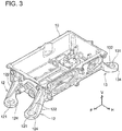
- FIG. 3 is a perspective view of a lower portion of the casing 10.
- the power converter 20 and the housing 30 are electrically connected by six power cables 19.
- the housing 30 houses two motors 3, and the six power cables 19 transmit two sets of three-phase AC.
- the upper surface of the housing 30 is inclined downward toward the front.
- the upper surface of the housing 30 is provided with a base 31 at its front portion and a base 32 at its back portion.
- each of the front legs 12 extend downward from a front portion of the casing 10 for the power converter 20 (see FIG. 3 ).
- Each of the front legs 12 is provided with a rib 122 and a flat foot 124.
- Each rib 122 has its upper end coupled to the front portion of the casing 10 and has its lower end coupled to the foot 124.
- Each foot 124 has a through hole 121 provided therein.
- each of the front legs 12 is fixed to the base 31 of the housing 30 with a bolt 15.
- the bolts 15 are disposed such that a longitudinal direction thereof is directed to a vertical direction and pass through the through holes 121 of the front legs 12 (see FIG. 3 ) to fix the front legs 12.
- Each of the back legs 13 also extend downward from a back portion of the casing 10.
- Each of the back legs 13 is provided with a rib 132 and a flat foot 134.
- Each rib 132 has its upper end coupled to the back portion of the casing 10 and has its lower end coupled to the foot 134.
- Each foot 134 has a through hole 131 provided therein.
- each of the back legs 13 is fixed to the base 32 of the housing 30 with a bolt 16.
- the bolts 16 are also disposed such that a longitudinal direction thereof is directed to the vertical direction and pass through the through holes 131 of the back legs 13 (see FIG. 3 ) to fix the back legs 13.
- the front legs 12 and the back legs 13 are integrally configured with the casing 10. Specifically, the front legs 12 and the back legs 13 are integrally configured with the casing 10 by aluminum injection molding. The front legs 12 and the back legs 13 integrally configured with the casing 10 can be realized at a low cost.
- the casing 10 is supported above the housing 30 by the front legs 12 and the back legs 13 that extend downward therefrom, with a space SP provided between the casing 10 and the housing 30.
- vibration isolators 14 are interposed between the base 31 (the housing 30) and the front legs 12.
- the vibration isolators 14 are also interposed between the base 32 (the housing 30) and the back legs 13.
- the casing 10 is supported by the housing 30 via the vibration isolators 14.
- the vibration isolators 14 attenuate vibrations transmitted from the housing 30 to the casing 10.
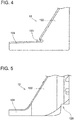
- FIG. 4 shows an enlarged side view of a lower portion of one of the front legs 12.
- a notch 123 (a weak portion) is provided at a boundary between the foot 124 and the rib 122.
- the front leg 12 is configured to break or deform from the notch 123 (the weak portion) that serves as a starting point, prior to break of fixed portions between the front legs 12 and the housing 30 (i.e., the base 31), when crash load is applied to the casing 10.
- the front leg 12 breaks or deforms from the notch 123 (the weak portion) serving as the starting point upon crash load being applied, break of the fixed portions between the front legs 12 and the housing 30 (i.e., the base 31) can be avoided.
- a high-voltage component in the housing 30 (a component of the motors 3) may be exposed. Such break of the housing 30 can be prevented in the structure 2 in the embodiment.
- the notch 123 (the weak portion) only needs to be provided in at least one of the four legs.
- a load applied to the other legs increases, as a result of which the other legs break or deform successively in a chain-reaction manner. Consequently, the casing 10 is moved backward and an impact on the casing 10 is mitigated.
- Each of all the legs may be provided with the notch 123 (the weak portion).
- FIG. 5 shows a side view of one of the front legs 12 in a variant.
- the weak portion may be a notch 129 provided on a back side of the rib 122.
- FIG. 6 shows a perspective view of the casing 10 for the power converter 20 and a housing 30c in a variant.
- FIG. 6 depicts the housing 30c in a simplified manner.
- the housing 30c includes walls 301 at a front portion of its upper surface.
- the walls 301 respectively engage with the front legs 12.
- the power converter 20 is placed above the housing 30c with the front legs 12 contacting the walls 301. Since the walls 301 support the power converter 20, the power converter 20 stays above the housing 30c even without bolts. In this state, bolts for fixing the casing 10 can be attached to the housing 30c. With the walls 301 provided, work for fixing the power converter 20 to the housing 30 can be facilitated.
- FIG. 7 is a side view of a power converter 20a and a housing 30a.
- FIG. 8 is a perspective view of the power converter 20a.
- a casing 10a for the power converter 20a is provided with legs (front legs 12a and back legs 13a).
- the front legs 12a extend downward from a front portion of the casing 10a.
- the back legs 13a extend downward from a back portion of the casing 10a.
- the front legs 12a and the back legs 13a are integrally configured with the casing 10a.
- Vertical walls 31a are provided at an upper front portion of the housing 30a.
- the front legs 12a are fixed to the vertical walls 31a of the housing 30a with bolts 15a.
- the bolts 15a are fixed to the vertical walls 31a of the housing 30a with a longitudinal direction of the bolts 15a directed to a lateral direction of the vehicle.
- vertical walls 32a are provided at an upper back portion of the housing 30a.
- the back legs 13a are fixed to the vertical walls 32a of the housing 30a with bolts 16a that are disposed such that a longitudinal direction of the bolts 16a is directed to the lateral direction of the vehicle.
- Lower ends of the front legs 12a and lower ends of the back legs 13a are fixed to the housing 30a with the space SP provided between a lower surface of the casing 10a and the housing 30a.
- a notch 123a is provided in one of the front legs 12a.
- the front leg 12a breaks or deforms from the notch 123a prior to break of fixed portions between the legs and the housing 30a.
- the one front leg 12a breaks or deforms, a load applied to the remaining legs increases. Consequently, the remaining legs also break or deform successively.
- break of the housing 30a can be avoided, and an impact applied to the casing 10a is mitigated due to the casing 10a being moved.
- Each of the front legs 12a is fixed to the housing 30a with the vibration isolator 14 interposed therebetween.
- Each of the back legs 13a is also fixed to the housing 30a with the vibration isolator 14 interposed therebetween.
- FIG. 9 is a side view showing a relation between a power converter 20b and a housing 30b (i.e., the structure 2b).
- a casing 10b for the power converter 20b is provided with legs (front legs 12b and back legs 13b).
- the front legs 12b extend downward from a front portion of the casing 10b.
- the back legs 13b extend downward from a back portion of the casing 10b.
- the front legs 12b and the back legs 13b are integrally configured with the casing 10b.
- a vertical wall 31b is provided at an upper front portion of the housing 30b.
- the front legs 12b are fixed to the vertical wall 31b of the housing 30b with bolts 15b.
- the bolts 15b are fixed to the housing 30b such that a longitudinal direction of the bolts 15b is directed to a front-back direction of the vehicle.
- a vertical wall 32b is provided at an upper back portion of the housing 30b.
- the back legs 13b are fixed to the vertical wall 32b of the housing 30b with bolts 16b.
- the bolts 16b are fixed to the housing 30b such that a longitudinal direction of the bolts 16b is directed to the front-back direction of the vehicle.
- the vibration isolators 14 are interposed between the vertical wall 31b of the housing 30b and the front legs 12b, and the vibration isolators 14 are also interposed between the vertical wall 32b and the back legs 13b.
- a notch 123b is provided in one of the front legs 12b.
- the front leg 12b breaks or deforms from the notch 123b prior to break of fixed portions between the legs and the housing 30b.
- the one front leg 12b breaks or deforms, a load applied to the remaining legs increases. Consequently, the remaining legs also break or deform successively.
- break of the housing 30b can be avoided, and an impact applied to the casing 10b is mitigated due to the casing 10b being moved.
- the structures disclosed herein may be applied to a power converter mounted in a back portion of a vehicle.
- the weak portion may be provided in one of the legs or in each of the legs.
Abstract
Description
- The teaching disclosed herein relates to a structure of mounting a power converter in a vehicle. The power converter is configured to convert electric power of a DC power source into driving power for an electric traction motor.
- An electric vehicle (including a hybrid vehicle and a fuel-cell vehicle) includes a power converter configured to convert electric power of a DC power source into driving power for a traction motor. Examples of such power converter are described in Japanese Patent Application Publication No.
2016-140200 2014-114870 2013-193634 Patent Literatures Patent Literatures Patent Literature 2 describes that vibration isolators are interposed between the casing of the power converter and the brackets. A structure of mounting the power converter in a vehicle described in each ofPatent Literatures - The disclosure herein provides a structure of mounting a power converter above a motor housing at a lower cost than that in a case of using a bracket that is a separate component from a converter casing.
- The disclosure herein provides a structure of mounting a power converter, which is configured to convert DC power of a power source into driving power for a traction motor, in a vehicle. A converter casing of the power converter may include legs extending downward from the converter casing. The legs may be integrally configured with the converter casing. Lower ends of the legs may be fixed to an upper portion of a motor housing that houses the traction motor, with a space provided between the motor housing and a lower surface of the converter casing. A weak portion may be provided in at least one of the legs, and the weak portion may be configured to break or deform prior to break of fixed portions between the legs and the motor housing when crash load is applied to the converter casing.
- The structure disclosed herein adopts the converter casing including the legs, instead of a bracket that is a separate component from the converter casing. The legs are integrally configured with the converter casing, and thus they can be formed simultaneously with the converter casing. Therefore, the converter casing including the legs can be realized at a lower cost than that in a case of adopting an independent bracket.
- Moreover, in the above-described structure, when a crash occurs, the at least one of the legs may breaks or deforms at the weak portion prior to break of the fixed portions between the legs and the motor housing. Accordingly, break of the motor housing (the fixed portions) is prevented. If break of the motor housing that houses the traction motor occurs, an internal high-voltage component (a component of the traction motor) may thereby be exposed. The structure disclosed herein may avoid the break of the motor housing.
- Further, break or deformation of the at least one of the legs causes the converter casing to move, and an impact applied to the converter casing is thereby mitigated. When the at least one of the legs breaks or deforms, a load applied to the other legs increases, as a result of which the other legs may break or deform successively in a chain-reaction manner. Consequently, the converter casing is moved and an impact on the power converter is mitigated. The weak portion may be provided in each of two or more of the legs. The weak portion may typically be a notch provided in the at least one of the legs.
- In the structure disclosed herein, vibration isolators may be provided between the motor housing and the legs of the converter casing. The vibration isolators reduce vibrations transmitted from the motor housing to the converter casing.
- Each of the lower ends of the legs may be fixed to the motor housing with a bolt, and the bolts may be fixed to the motor housing such that a longitudinal direction of the bolts is directed to a vertical direction. Alternatively, the bolts that fix the lower ends of the legs may be fixed to the motor housing such that the longitudinal direction of the bolts is directed to a lateral direction of the vehicle. In either of these cases, work for inserting the bolts is facilitated.
- The bolts that fix the lower ends of the legs may be fixed to the motor housing such that the longitudinal direction of the bolts is directed to a front-back direction of the vehicle. In this case, each of bolts insertion portions at the lower ends of the legs enlarges in the lateral direction of the vehicle and the vertical direction. The bolt insertion portions do not need to enlarge in the front-back direction of the vehicle, so an overall length of the converter casing including the bolt insertion portions is shortened.
- The details and further improvements of the teaching disclosed herein will be described in the following "DETAILED DESCRIPTION".
-
-
FIG. 1 is a perspective view showing an example of a component layout in a front compartment that includes a structure of mounting a power converter in a vehicle in a first embodiment. -
FIG. 2 is a side view of a housing and the power converter. -
FIG. 3 is a perspective view of a lower portion of a casing. -
FIG. 4 is an enlarged side view of a lower portion of a front leg. -
FIG. 5 is an enlarged side view of a front leg in a variant. -
FIG. 6 is a perspective view of the power converter and a housing in a variant. -
FIG. 7 is a side view for explaining a structure of mounting a power converter in a vehicle in a second embodiment. -
FIG. 8 is a perspective view of the power converter in the structure in the second embodiment. -
FIG. 9 is a side view for explaining a structure of mounting a power converter in a vehicle in a third embodiment. - Representative, non-limiting examples of the present disclosure will now be described in further detail with reference to the attached drawings. This detailed description is merely intended to teach a person of skill in the art further details for practicing preferred aspects of the present teachings and is not intended to limit the scope of the present disclosure. Furthermore, each of the additional features and teachings disclosed below may be utilized separately or in conjunction with other features and teachings to provide improved structures of mounting a power converter in a vehicle.
- Moreover, combinations of features and steps disclosed in the following detailed description may not be necessary to practice the disclosure in the broadest sense, and are instead taught merely to particularly describe representative examples of the present disclosure. Furthermore, various features of the above-described and below-described representative examples, as well as the various independent and dependent claims, may be combined in ways that are not specifically and explicitly enumerated in order to provide additional useful embodiments of the present teachings.
- All features disclosed in the description and/or the claims are intended to be disclosed separately and independently from each other for the purpose of original written disclosure, as well as for the purpose of restricting the claimed subject matter, independent of the compositions of the features in the embodiments and/or the claims. In addition, all value ranges or indications of groups of entities are intended to disclose every possible intermediate value or intermediate entity for the purpose of original written disclosure, as well as for the purpose of restricting the claimed subject matter.
- (First Embodiment) With reference to the drawings, a
structure 2 of mounting a power converter in a vehicle in a first embodiment will be described. The structure in the embodiment is applied to a hybrid vehicle that includes both of a traction motor and an engine.FIG. 1 shows a component layout in afront compartment 90 of ahybrid vehicle 100. Thehybrid vehicle 100 has anengine 98,motors 3, and apower converter 20 mounted in thefront compartment 90 of the vehicle. Thepower converter 20 is a device configured to convert electric power of a main battery, which is not shown, into driving power for themotors 3. In thefront compartment 90, thepower converter 20 is fixed above ahousing 30. Thestructure 2 in the first embodiment is applied to thepower converter 20. - The
housing 30 houses themotors 3, a power distribution mechanism, and a differential gear. In addition to theengine 98, thepower converter 20, and thehousing 30, various devices such as abattery 95 are disposed in thefront compartment 90, but description of these devices will be omitted. It should be noted thatFIG. 1 schematically depicts thehousing 30, theengine 98, and the like.FIG. 1 also depicts thepower converter 20 in a simplified manner. For a detailed shape of thepower converter 20,FIGS. 2 and3 should be referred to. - In a coordinate system in the drawing, an F-axis indicates a front direction of the vehicle, a V-axis indicates a vertical direction of the vehicle, and an H-axis indicates a vehicle-width direction (a lateral direction of the vehicle). The meanings of these signs in the coordinate system are the same in the subsequent drawings. Further, expressions such as "front surface", "back surface", "front portion", "back portion", and the like will hereinafter be used for components mounted in the
front compartment 90. In these expressions, "front" means a front side of the vehicle, and "back" means a back side of the vehicle. - As described above, the
housing 30 houses the power distribution mechanism and the differential gear, in addition to themotors 3. The power distribution mechanism is a gear set configured to combine or distribute output torque of theengine 98 and output torque of themotors 3. According to circumstances, the power distribution mechanism divides the output torque of theengine 98 and transmits it to the differential gear and themotors 3. Since thehousing 30 houses the differential gear therein, thehousing 30 is, in other words, a casing of the motors and a transaxle. Thehousing 30 is formed, for example, by aluminum die casting or aluminum machining. - The
engine 98 and thehousing 30 are coupled to be adjacent to each other in the vehicle-width direction. Theengine 98 and thehousing 30bridge side members 96 that ensure structural strength of the vehicle.FIG. 1 only depicts one of theside members 96, however, another side member extends at a lower-left side of theengine 98 inFIG. 1 . Theengine 98 and thehousing 30 bridge the two side members. - As described above, the
power converter 20 is a device configured to convert electric power of the main battery, which is not shown, into driving power for themotors 3. More specifically, thepower converter 20 boosts a voltage of the electric power of the main battery, and then converts the electric power into AC power having a frequency corresponding to a number of revolutions of the motors. Moreover, thepower converter 20 may convert AC power generated by the motors 3 (regenerative electric power) into DC power and may further step down a voltage of the DC power. The electric power, the voltage of which has been stepped down, is used to charge the main battery. - The
power converter 20 is supported with a space provided between thepower converter 20 and an upper surface of thehousing 30, the details of which will be described later.Front legs 12 andback legs 13 extend downward from acasing 10 of thepower converter 20, and lower ends of thefront legs 12 and lower ends of theback legs 13 are fixed to thehousing 30. With reference toFIGS. 2 and3 as well asFIG. 1 , a relation between thehousing 30 and the power converter 20 (i.e., the structure 2) will be described in detail.FIG. 2 is a side view of thepower converter 20 and thehousing 30. The "side view" is a view when seen in the vehicle-width direction (in the H-axis direction in the drawing).FIG. 3 is a perspective view of a lower portion of thecasing 10. - The
power converter 20 and thehousing 30 are electrically connected by sixpower cables 19. Thehousing 30 houses twomotors 3, and the sixpower cables 19 transmit two sets of three-phase AC. - The upper surface of the
housing 30 is inclined downward toward the front. The upper surface of thehousing 30 is provided with a base 31 at its front portion and a base 32 at its back portion. - Meanwhile, two legs (the front legs 12) extend downward from a front portion of the
casing 10 for the power converter 20 (seeFIG. 3 ). Each of thefront legs 12 is provided with arib 122 and aflat foot 124. Eachrib 122 has its upper end coupled to the front portion of thecasing 10 and has its lower end coupled to thefoot 124. Eachfoot 124 has a throughhole 121 provided therein. As shown inFIG. 2 , each of thefront legs 12 is fixed to thebase 31 of thehousing 30 with abolt 15. Thebolts 15 are disposed such that a longitudinal direction thereof is directed to a vertical direction and pass through the throughholes 121 of the front legs 12 (seeFIG. 3 ) to fix thefront legs 12. - Two legs (the back legs 13) also extend downward from a back portion of the
casing 10. Each of theback legs 13 is provided with arib 132 and aflat foot 134. Eachrib 132 has its upper end coupled to the back portion of thecasing 10 and has its lower end coupled to thefoot 134. Eachfoot 134 has a throughhole 131 provided therein. As shown inFIG. 2 , each of theback legs 13 is fixed to thebase 32 of thehousing 30 with abolt 16. Thebolts 16 are also disposed such that a longitudinal direction thereof is directed to the vertical direction and pass through the throughholes 131 of the back legs 13 (seeFIG. 3 ) to fix theback legs 13. - The
front legs 12 and theback legs 13 are integrally configured with thecasing 10. Specifically, thefront legs 12 and theback legs 13 are integrally configured with thecasing 10 by aluminum injection molding. Thefront legs 12 and theback legs 13 integrally configured with thecasing 10 can be realized at a low cost. - The
casing 10 is supported above thehousing 30 by thefront legs 12 and theback legs 13 that extend downward therefrom, with a space SP provided between thecasing 10 and thehousing 30. Moreover,vibration isolators 14 are interposed between the base 31 (the housing 30) and thefront legs 12. Thevibration isolators 14 are also interposed between the base 32 (the housing 30) and theback legs 13. Thecasing 10 is supported by thehousing 30 via thevibration isolators 14. Thevibration isolators 14 attenuate vibrations transmitted from thehousing 30 to thecasing 10. -
FIG. 4 shows an enlarged side view of a lower portion of one of thefront legs 12. A notch 123 (a weak portion) is provided at a boundary between thefoot 124 and therib 122. Thefront leg 12 is configured to break or deform from the notch 123 (the weak portion) that serves as a starting point, prior to break of fixed portions between thefront legs 12 and the housing 30 (i.e., the base 31), when crash load is applied to thecasing 10. When thefront leg 12 breaks or deforms from the notch 123 (the weak portion) serving as the starting point upon crash load being applied, break of the fixed portions between thefront legs 12 and the housing 30 (i.e., the base 31) can be avoided. If break of thehousing 30 occurs, a high-voltage component in the housing 30 (a component of the motors 3) may be exposed. Such break of thehousing 30 can be prevented in thestructure 2 in the embodiment. - The notch 123 (the weak portion) only needs to be provided in at least one of the four legs. When one of the
front legs 12 breaks or deforms, a load applied to the other legs increases, as a result of which the other legs break or deform successively in a chain-reaction manner. Consequently, thecasing 10 is moved backward and an impact on thecasing 10 is mitigated. Each of all the legs may be provided with the notch 123 (the weak portion). -
FIG. 5 shows a side view of one of thefront legs 12 in a variant. As shown inFIG. 5 , the weak portion may be anotch 129 provided on a back side of therib 122. -
FIG. 6 shows a perspective view of thecasing 10 for thepower converter 20 and ahousing 30c in a variant.FIG. 6 depicts thehousing 30c in a simplified manner. Thehousing 30c includeswalls 301 at a front portion of its upper surface. Thewalls 301 respectively engage with thefront legs 12. When thepower converter 20 is to be fixed, thepower converter 20 is placed above thehousing 30c with thefront legs 12 contacting thewalls 301. Since thewalls 301 support thepower converter 20, thepower converter 20 stays above thehousing 30c even without bolts. In this state, bolts for fixing thecasing 10 can be attached to thehousing 30c. With thewalls 301 provided, work for fixing thepower converter 20 to thehousing 30 can be facilitated. - (Second Embodiment) With reference to
FIGS. 7 and8 , astructure 2a of mounting a power converter in a vehicle in a second embodiment will be described.FIG. 7 is a side view of apower converter 20a and ahousing 30a.FIG. 8 is a perspective view of thepower converter 20a. Acasing 10a for thepower converter 20a is provided with legs (front legs 12a andback legs 13a). Thefront legs 12a extend downward from a front portion of thecasing 10a. Theback legs 13a extend downward from a back portion of thecasing 10a. Thefront legs 12a and theback legs 13a are integrally configured with thecasing 10a. -
Vertical walls 31a are provided at an upper front portion of thehousing 30a. Thefront legs 12a are fixed to thevertical walls 31a of thehousing 30a withbolts 15a. Thebolts 15a are fixed to thevertical walls 31a of thehousing 30a with a longitudinal direction of thebolts 15a directed to a lateral direction of the vehicle. - Additionally,
vertical walls 32a are provided at an upper back portion of thehousing 30a. Theback legs 13a are fixed to thevertical walls 32a of thehousing 30a withbolts 16a that are disposed such that a longitudinal direction of thebolts 16a is directed to the lateral direction of the vehicle. Lower ends of thefront legs 12a and lower ends of theback legs 13a are fixed to thehousing 30a with the space SP provided between a lower surface of thecasing 10a and thehousing 30a. - A
notch 123a is provided in one of thefront legs 12a. When crash load is applied to thecasing 10a, thefront leg 12a breaks or deforms from thenotch 123a prior to break of fixed portions between the legs and thehousing 30a. When the onefront leg 12a breaks or deforms, a load applied to the remaining legs increases. Consequently, the remaining legs also break or deform successively. In thestructure 2a, as in thestructure 2 in the first embodiment, break of thehousing 30a can be avoided, and an impact applied to thecasing 10a is mitigated due to thecasing 10a being moved. - Each of the
front legs 12a is fixed to thehousing 30a with thevibration isolator 14 interposed therebetween. Each of theback legs 13a is also fixed to thehousing 30a with thevibration isolator 14 interposed therebetween. - In the
structure 2 in which the longitudinal direction of thebolts structure 2a in which the longitudinal direction of thebolts - (Third Embodiment) With reference to
FIG. 9 , astructure 2b of mounting a power converter in a vehicle in a third embodiment will be described.FIG. 9 is a side view showing a relation between apower converter 20b and ahousing 30b (i.e., thestructure 2b). Acasing 10b for thepower converter 20b is provided with legs (front legs 12b andback legs 13b). Thefront legs 12b extend downward from a front portion of thecasing 10b. Theback legs 13b extend downward from a back portion of thecasing 10b. Thefront legs 12b and theback legs 13b are integrally configured with thecasing 10b. - A
vertical wall 31b is provided at an upper front portion of thehousing 30b. Thefront legs 12b are fixed to thevertical wall 31b of thehousing 30b withbolts 15b. Thebolts 15b are fixed to thehousing 30b such that a longitudinal direction of thebolts 15b is directed to a front-back direction of the vehicle. Additionally, avertical wall 32b is provided at an upper back portion of thehousing 30b. Theback legs 13b are fixed to thevertical wall 32b of thehousing 30b withbolts 16b. Thebolts 16b are fixed to thehousing 30b such that a longitudinal direction of thebolts 16b is directed to the front-back direction of the vehicle. Lower ends of thefront legs 12b and lower ends of theback legs 13b are fixed to thehousing 30b, and thereby the space SP is ensured between a lower surface of thecasing 10b and thehousing 30b. In thestructure 2b in which the longitudinal direction of thebolts casing 10b including the legs (thefront legs 12b and theback legs 13b) can be shortened. - The
vibration isolators 14 are interposed between thevertical wall 31b of thehousing 30b and thefront legs 12b, and thevibration isolators 14 are also interposed between thevertical wall 32b and theback legs 13b. - A
notch 123b is provided in one of thefront legs 12b. When crash load is applied to thecasing 10b, thefront leg 12b breaks or deforms from thenotch 123b prior to break of fixed portions between the legs and thehousing 30b. When the onefront leg 12b breaks or deforms, a load applied to the remaining legs increases. Consequently, the remaining legs also break or deform successively. In thestructure 2b as well, as in thestructure 2 in the first embodiment, break of thehousing 30b can be avoided, and an impact applied to thecasing 10b is mitigated due to thecasing 10b being moved. - Some points to be noted regarding to the teaching described in the embodiments will be listed. The structures disclosed herein may be applied to a power converter mounted in a back portion of a vehicle. The weak portion (notch) may be provided in one of the legs or in each of the legs.
Claims (6)
- A structure (2, 2a, 2b) of mounting a power converter (20, 20a, 20b) in a vehicle (100), the structure comprising:a converter casing (10, 10a, 10b) of the power converter (20, 20a, 20b), the converter casing (10, 10a, 10b) including legs (12, 12a, 12b, 13, 13a, 13b) connected to the converter casing (10, 10a, 10b) and extending downward; anda motor housing (30, 30a, 30b, 30c) that houses a traction motor (3),characterized in that:the legs (12, 12a, 12b, 13, 13a, 13b) are integrally configured with the converter casing (10, 10a, 10b);lower ends of the legs (12, 12a, 12b, 13, 13a, 13b) are fixed to an upper portion of the motor housing (30, 30a, 30b, 30c) with a space provided between the motor housing (30, 30a, 30b, 30c) and a lower surface of the converter casing (10, 10a, 10b), anda weak portion (123, 123a, 123b, 129) is provided in at least one of the legs (12, 12a, 12b, 13, 13a, 13b), the weak portion (123, 123a, 123b, 129) configured to break or deform prior to break of fixed portions between the legs (12, 12a, 12b, 13, 13a, 13b) and the motor housing (30, 30a, 30b, 30c) when crash load is applied to the converter casing (10, 10a, 10b).
- The structure (2, 2a, 2b) according to claim 1, characterized in that the weak portion (123, 123a, 123b, 129) is a notch (123, 123a, 123b, 129) provided in the at least one of the legs (12, 12a, 12b, 13, 13a, 13b).
- The structure (2, 2a, 2b) according to claim 1, characterized in that vibration isolators (14) are provided between the motor housing (30, 30a, 30b, 30c) and the legs (12, 12a, 12b, 13, 13a, 13b).
- The structure (2) according to any one of claims 1 to 3,
characterized in that:each of the legs (12,13) is fixed to the motor housing (30) with a bolt (15, 16),the bolts (15, 16) are fixed to the motor housing (30) such that a longitudinal direction of the bolts (15, 16) is directed to a vertical direction. - The structure (2a) according to any one of claims 1 to 3,
characterized in that:each of the legs (12a,13a) is fixed to the motor housing (30a) with a bolt (15a, 16a),the bolts (15a, 16a) are fixed to the motor housing (30a) such that a longitudinal direction of the bolts (15a, 16a) is directed to a lateral direction of the vehicle. - The structure (2b) according to any one of claims 1 to 3,
characterized in that:each of the legs (12b,13b) is fixed to the motor housing (30b) with a bolt (15b, 16b),the bolts (15b, 16b) are fixed to the motor housing (30b) such that a longitudinal direction of the bolts (15b, 16b) is directed to a front-back direction of the vehicle.
Applications Claiming Priority (1)
| Application Number | Priority Date | Filing Date | Title |
|---|---|---|---|
| JP2018099880A JP2019202681A (en) | 2018-05-24 | 2018-05-24 | Structure of mounting power converter in vehicle |
Publications (1)
| Publication Number | Publication Date |
|---|---|
| EP3572260A1 true EP3572260A1 (en) | 2019-11-27 |
Family
ID=66286250
Family Applications (1)
| Application Number | Title | Priority Date | Filing Date |
|---|---|---|---|
| EP19171146.4A Withdrawn EP3572260A1 (en) | 2018-05-24 | 2019-04-25 | Structure of mounting power converter in vehicle |
Country Status (7)
| Country | Link |
|---|---|
| US (1) | US20190359068A1 (en) |
| EP (1) | EP3572260A1 (en) |
| JP (1) | JP2019202681A (en) |
| KR (1) | KR102141108B1 (en) |
| CN (1) | CN110535355A (en) |
| BR (1) | BR102019009427A2 (en) |
| RU (1) | RU2711947C1 (en) |
Families Citing this family (5)
| Publication number | Priority date | Publication date | Assignee | Title |
|---|---|---|---|---|
| JP7404794B2 (en) | 2019-11-07 | 2023-12-26 | 株式会社デンソー | rotating electric machine |
| CN114829175B (en) * | 2019-12-25 | 2022-12-13 | 株式会社明电舍 | Mounting structure of motor assembly |
| US11858550B2 (en) | 2020-09-21 | 2024-01-02 | Ford Global Technologies, Llc | Electrified vehicle module brace assembly and supporting method |
| JP7447872B2 (en) | 2021-06-21 | 2024-03-12 | トヨタ自動車株式会社 | power equipment |
| DE102021127846B3 (en) * | 2021-10-26 | 2022-11-24 | Dr. Ing. H.C. F. Porsche Aktiengesellschaft | Motor vehicle and method for mounting a housing on a bodyshell of a motor vehicle |
Citations (6)
| Publication number | Priority date | Publication date | Assignee | Title |
|---|---|---|---|---|
| JP2012201231A (en) * | 2011-03-25 | 2012-10-22 | Toyota Motor Corp | Vehicular housing |
| JP2013193634A (en) | 2012-03-22 | 2013-09-30 | Toyota Motor Corp | Electric vehicle |
| JP2014114870A (en) | 2012-12-10 | 2014-06-26 | Toyota Motor Corp | On-vehicle structure of electronic apparatus |
| JP2016140200A (en) | 2015-01-28 | 2016-08-04 | 本田技研工業株式会社 | Integrated type unit |
| JP2017081503A (en) * | 2015-10-30 | 2017-05-18 | トヨタ自動車株式会社 | On-vehicle structure of power converter |
| WO2017137679A1 (en) * | 2016-02-09 | 2017-08-17 | Renault S.A.S | Device for supporting a motor vehicle component |
Family Cites Families (10)
| Publication number | Priority date | Publication date | Assignee | Title |
|---|---|---|---|---|
| RU2175919C1 (en) * | 2000-03-28 | 2001-11-20 | Открытое акционерное общество "АВТОВАЗ" | Vehicle mounting unit |
| DE10314030B4 (en) * | 2003-03-28 | 2005-07-14 | A. Raymond & Cie | Device for fastening a housing, in particular that of a motor vehicle battery, to a carrier |
| JP5128373B2 (en) * | 2008-06-10 | 2013-01-23 | 本田技研工業株式会社 | Vehicle drive motor unit |
| WO2012064713A1 (en) * | 2010-11-08 | 2012-05-18 | William Randall Stuchlik | Random orbit disc scrubber |
| JP5880491B2 (en) * | 2013-07-01 | 2016-03-09 | トヨタ自動車株式会社 | Inverter case |
| DE102013015490B4 (en) * | 2013-09-19 | 2019-10-17 | Bury Sp.Z.O.O | Holding device for fastening an electronic device in a motor vehicle |
| RU2565427C2 (en) * | 2013-11-26 | 2015-10-20 | Акционерное общество "Информационные спутниковые системы" имени академика М.Ф. Решетнёва" | Bracket |
| JP6136075B2 (en) * | 2014-11-14 | 2017-05-31 | トヨタ自動車株式会社 | vehicle |
| JP6082417B2 (en) * | 2015-03-13 | 2017-02-15 | 本田技研工業株式会社 | Fuel cell system |
| JP6341233B2 (en) * | 2016-06-13 | 2018-06-13 | トヨタ自動車株式会社 | In-vehicle structure of power converter |
-
2018
- 2018-05-24 JP JP2018099880A patent/JP2019202681A/en active Pending
-
2019
- 2019-04-19 US US16/389,278 patent/US20190359068A1/en not_active Abandoned
- 2019-04-25 EP EP19171146.4A patent/EP3572260A1/en not_active Withdrawn
- 2019-05-08 BR BR102019009427A patent/BR102019009427A2/en not_active IP Right Cessation
- 2019-05-20 RU RU2019115342A patent/RU2711947C1/en active
- 2019-05-22 KR KR1020190060292A patent/KR102141108B1/en active IP Right Grant
- 2019-05-22 CN CN201910428547.4A patent/CN110535355A/en not_active Withdrawn
Patent Citations (6)
| Publication number | Priority date | Publication date | Assignee | Title |
|---|---|---|---|---|
| JP2012201231A (en) * | 2011-03-25 | 2012-10-22 | Toyota Motor Corp | Vehicular housing |
| JP2013193634A (en) | 2012-03-22 | 2013-09-30 | Toyota Motor Corp | Electric vehicle |
| JP2014114870A (en) | 2012-12-10 | 2014-06-26 | Toyota Motor Corp | On-vehicle structure of electronic apparatus |
| JP2016140200A (en) | 2015-01-28 | 2016-08-04 | 本田技研工業株式会社 | Integrated type unit |
| JP2017081503A (en) * | 2015-10-30 | 2017-05-18 | トヨタ自動車株式会社 | On-vehicle structure of power converter |
| WO2017137679A1 (en) * | 2016-02-09 | 2017-08-17 | Renault S.A.S | Device for supporting a motor vehicle component |
Also Published As
| Publication number | Publication date |
|---|---|
| KR20190134509A (en) | 2019-12-04 |
| US20190359068A1 (en) | 2019-11-28 |
| CN110535355A (en) | 2019-12-03 |
| JP2019202681A (en) | 2019-11-28 |
| RU2711947C1 (en) | 2020-01-23 |
| KR102141108B1 (en) | 2020-08-04 |
| BR102019009427A2 (en) | 2019-12-10 |
Similar Documents
| Publication | Publication Date | Title |
|---|---|---|
| EP3572260A1 (en) | Structure of mounting power converter in vehicle | |
| US9630501B2 (en) | Vehicle | |
| EP3789273A1 (en) | Vehicle front structure and vehicle | |
| US20090294626A1 (en) | Mounting structure | |
| JP2014114870A (en) | On-vehicle structure of electronic apparatus | |
| US10189353B2 (en) | On-vehicle structure | |
| CN104810962A (en) | Connector protection structure for motor | |
| CN109866707B (en) | Structure for mounting electrical equipment on vehicle | |
| JP2014015171A (en) | Fixing structure of on-vehicle device | |
| US11027679B2 (en) | Electrical device | |
| CN112477599A (en) | Structure for mounting electrical equipment on vehicle | |
| JP2017081503A (en) | On-vehicle structure of power converter | |
| JP2017007553A (en) | Electric vehicle | |
| JP2015133866A (en) | connection structure | |
| JP6981228B2 (en) | Power control unit mounting structure | |
| JP2019077355A (en) | On-vehicle structure of power control device | |
| JP6520190B2 (en) | Wiring structure of vehicle harness | |
| JP2021109478A (en) | On-vehicle structure of electric device | |
| JP2018079733A (en) | On-vehicle structure of electronic apparatus | |
| WO2021176602A1 (en) | Vehicle-mounted structure of inverter | |
| JP7287208B2 (en) | Vehicle electrical equipment support structure | |
| JP6950606B2 (en) | Support structure of the power controller that controls the traction motor | |
| JP2021115893A (en) | On-vehicle structure for electric apparatus | |
| JP7234824B2 (en) | Installation structure of the motor drive device | |
| CN111661166B (en) | Vehicle front structure |
Legal Events
| Date | Code | Title | Description |
|---|---|---|---|
| PUAI | Public reference made under article 153(3) epc to a published international application that has entered the european phase |
Free format text: ORIGINAL CODE: 0009012 |
|
| STAA | Information on the status of an ep patent application or granted ep patent |
Free format text: STATUS: REQUEST FOR EXAMINATION WAS MADE |
|
| 17P | Request for examination filed |
Effective date: 20190425 |
|
| AK | Designated contracting states |
Kind code of ref document: A1 Designated state(s): AL AT BE BG CH CY CZ DE DK EE ES FI FR GB GR HR HU IE IS IT LI LT LU LV MC MK MT NL NO PL PT RO RS SE SI SK SM TR |
|
| AX | Request for extension of the european patent |
Extension state: BA ME |
|
| STAA | Information on the status of an ep patent application or granted ep patent |
Free format text: STATUS: EXAMINATION IS IN PROGRESS |
|
| 17Q | First examination report despatched |
Effective date: 20200807 |
|
| GRAP | Despatch of communication of intention to grant a patent |
Free format text: ORIGINAL CODE: EPIDOSNIGR1 |
|
| STAA | Information on the status of an ep patent application or granted ep patent |
Free format text: STATUS: GRANT OF PATENT IS INTENDED |
|
| INTG | Intention to grant announced |
Effective date: 20200911 |
|
| RAP1 | Party data changed (applicant data changed or rights of an application transferred) |
Owner name: TOYOTA JIDOSHA KABUSHIKI KAISHA |
|
| RIN1 | Information on inventor provided before grant (corrected) |
Inventor name: YAMANAKA, KENSHI Inventor name: MARUKAWA, NAOKI |
|
| STAA | Information on the status of an ep patent application or granted ep patent |
Free format text: STATUS: THE APPLICATION IS DEEMED TO BE WITHDRAWN |
|
| 18D | Application deemed to be withdrawn |
Effective date: 20210122 |