EP3572120A1 - Catheter device, comprising a valve for controlling a flow of a fluid through a catheter - Google Patents
Catheter device, comprising a valve for controlling a flow of a fluid through a catheter Download PDFInfo
- Publication number
- EP3572120A1 EP3572120A1 EP19185354.8A EP19185354A EP3572120A1 EP 3572120 A1 EP3572120 A1 EP 3572120A1 EP 19185354 A EP19185354 A EP 19185354A EP 3572120 A1 EP3572120 A1 EP 3572120A1
- Authority
- EP
- European Patent Office
- Prior art keywords
- valve
- catheter
- fluid
- drive
- closure element
- Prior art date
- Legal status (The legal status is an assumption and is not a legal conclusion. Google has not performed a legal analysis and makes no representation as to the accuracy of the status listed.)
- Pending
Links
- 239000012530 fluid Substances 0.000 title claims abstract description 82
- 230000005291 magnetic effect Effects 0.000 claims description 46
- 239000012528 membrane Substances 0.000 claims description 23
- 239000002245 particle Substances 0.000 claims description 20
- 230000001681 protective effect Effects 0.000 claims description 16
- 210000002376 aorta thoracic Anatomy 0.000 claims description 4
- 238000003780 insertion Methods 0.000 claims description 4
- 230000037431 insertion Effects 0.000 claims description 4
- 230000014759 maintenance of location Effects 0.000 claims description 4
- 239000002131 composite material Substances 0.000 claims 13
- 210000004379 membrane Anatomy 0.000 description 26
- 238000011010 flushing procedure Methods 0.000 description 14
- 230000002572 peristaltic effect Effects 0.000 description 10
- 238000005299 abrasion Methods 0.000 description 7
- 238000007789 sealing Methods 0.000 description 5
- 239000003795 chemical substances by application Substances 0.000 description 4
- 230000000694 effects Effects 0.000 description 4
- 238000005516 engineering process Methods 0.000 description 4
- 230000002262 irrigation Effects 0.000 description 4
- 238000003973 irrigation Methods 0.000 description 4
- 238000000926 separation method Methods 0.000 description 4
- 238000004140 cleaning Methods 0.000 description 3
- 238000013461 design Methods 0.000 description 3
- 210000001105 femoral artery Anatomy 0.000 description 3
- 230000005484 gravity Effects 0.000 description 3
- 239000007788 liquid Substances 0.000 description 3
- 239000007787 solid Substances 0.000 description 3
- 230000009471 action Effects 0.000 description 2
- 210000000709 aorta Anatomy 0.000 description 2
- 230000000903 blocking effect Effects 0.000 description 2
- 238000010276 construction Methods 0.000 description 2
- 230000004048 modification Effects 0.000 description 2
- 238000012986 modification Methods 0.000 description 2
- 239000011241 protective layer Substances 0.000 description 2
- 238000010926 purge Methods 0.000 description 2
- 238000005406 washing Methods 0.000 description 2
- 208000012886 Vertigo Diseases 0.000 description 1
- 238000011001 backwashing Methods 0.000 description 1
- 230000008901 benefit Effects 0.000 description 1
- 239000000356 contaminant Substances 0.000 description 1
- 230000008878 coupling Effects 0.000 description 1
- 238000010168 coupling process Methods 0.000 description 1
- 238000005859 coupling reaction Methods 0.000 description 1
- 230000001066 destructive effect Effects 0.000 description 1
- 239000003599 detergent Substances 0.000 description 1
- 239000013013 elastic material Substances 0.000 description 1
- 239000000806 elastomer Substances 0.000 description 1
- 229920001971 elastomer Polymers 0.000 description 1
- 230000005284 excitation Effects 0.000 description 1
- 230000005294 ferromagnetic effect Effects 0.000 description 1
- 239000003302 ferromagnetic material Substances 0.000 description 1
- 230000001771 impaired effect Effects 0.000 description 1
- 238000010348 incorporation Methods 0.000 description 1
- 230000036512 infertility Effects 0.000 description 1
- 238000009434 installation Methods 0.000 description 1
- 239000010410 layer Substances 0.000 description 1
- 210000005240 left ventricle Anatomy 0.000 description 1
- 230000007774 longterm Effects 0.000 description 1
- 238000005461 lubrication Methods 0.000 description 1
- 239000000463 material Substances 0.000 description 1
- 239000002184 metal Substances 0.000 description 1
- 238000005192 partition Methods 0.000 description 1
- 238000005086 pumping Methods 0.000 description 1
- 125000006850 spacer group Chemical group 0.000 description 1
- 230000001954 sterilising effect Effects 0.000 description 1
- 238000004659 sterilization and disinfection Methods 0.000 description 1
- 238000012546 transfer Methods 0.000 description 1
- 238000011144 upstream manufacturing Methods 0.000 description 1
- 238000004804 winding Methods 0.000 description 1
Images


Classifications
-
- A—HUMAN NECESSITIES
- A61—MEDICAL OR VETERINARY SCIENCE; HYGIENE
- A61M—DEVICES FOR INTRODUCING MEDIA INTO, OR ONTO, THE BODY; DEVICES FOR TRANSDUCING BODY MEDIA OR FOR TAKING MEDIA FROM THE BODY; DEVICES FOR PRODUCING OR ENDING SLEEP OR STUPOR
- A61M60/00—Blood pumps; Devices for mechanical circulatory actuation; Balloon pumps for circulatory assistance
- A61M60/80—Constructional details other than related to driving
- A61M60/855—Constructional details other than related to driving of implantable pumps or pumping devices
- A61M60/89—Valves
- A61M60/892—Active valves, i.e. actuated by an external force
-
- A—HUMAN NECESSITIES
- A61—MEDICAL OR VETERINARY SCIENCE; HYGIENE
- A61M—DEVICES FOR INTRODUCING MEDIA INTO, OR ONTO, THE BODY; DEVICES FOR TRANSDUCING BODY MEDIA OR FOR TAKING MEDIA FROM THE BODY; DEVICES FOR PRODUCING OR ENDING SLEEP OR STUPOR
- A61M60/00—Blood pumps; Devices for mechanical circulatory actuation; Balloon pumps for circulatory assistance
- A61M60/80—Constructional details other than related to driving
- A61M60/802—Constructional details other than related to driving of non-positive displacement blood pumps
- A61M60/818—Bearings
- A61M60/82—Magnetic bearings
-
- A—HUMAN NECESSITIES
- A61—MEDICAL OR VETERINARY SCIENCE; HYGIENE
- A61M—DEVICES FOR INTRODUCING MEDIA INTO, OR ONTO, THE BODY; DEVICES FOR TRANSDUCING BODY MEDIA OR FOR TAKING MEDIA FROM THE BODY; DEVICES FOR PRODUCING OR ENDING SLEEP OR STUPOR
- A61M25/00—Catheters; Hollow probes
- A61M25/0021—Catheters; Hollow probes characterised by the form of the tubing
- A61M25/0023—Catheters; Hollow probes characterised by the form of the tubing by the form of the lumen, e.g. cross-section, variable diameter
- A61M25/0026—Multi-lumen catheters with stationary elements
- A61M25/003—Multi-lumen catheters with stationary elements characterized by features relating to least one lumen located at the distal part of the catheter, e.g. filters, plugs or valves
-
- A—HUMAN NECESSITIES
- A61—MEDICAL OR VETERINARY SCIENCE; HYGIENE
- A61M—DEVICES FOR INTRODUCING MEDIA INTO, OR ONTO, THE BODY; DEVICES FOR TRANSDUCING BODY MEDIA OR FOR TAKING MEDIA FROM THE BODY; DEVICES FOR PRODUCING OR ENDING SLEEP OR STUPOR
- A61M25/00—Catheters; Hollow probes
- A61M25/0043—Catheters; Hollow probes characterised by structural features
-
- A—HUMAN NECESSITIES
- A61—MEDICAL OR VETERINARY SCIENCE; HYGIENE
- A61M—DEVICES FOR INTRODUCING MEDIA INTO, OR ONTO, THE BODY; DEVICES FOR TRANSDUCING BODY MEDIA OR FOR TAKING MEDIA FROM THE BODY; DEVICES FOR PRODUCING OR ENDING SLEEP OR STUPOR
- A61M25/00—Catheters; Hollow probes
- A61M25/10—Balloon catheters
- A61M25/1018—Balloon inflating or inflation-control devices
- A61M25/10184—Means for controlling or monitoring inflation or deflation
- A61M25/10185—Valves
-
- A—HUMAN NECESSITIES
- A61—MEDICAL OR VETERINARY SCIENCE; HYGIENE
- A61M—DEVICES FOR INTRODUCING MEDIA INTO, OR ONTO, THE BODY; DEVICES FOR TRANSDUCING BODY MEDIA OR FOR TAKING MEDIA FROM THE BODY; DEVICES FOR PRODUCING OR ENDING SLEEP OR STUPOR
- A61M39/00—Tubes, tube connectors, tube couplings, valves, access sites or the like, specially adapted for medical use
- A61M39/22—Valves or arrangement of valves
- A61M39/223—Multiway valves
-
- A—HUMAN NECESSITIES
- A61—MEDICAL OR VETERINARY SCIENCE; HYGIENE
- A61M—DEVICES FOR INTRODUCING MEDIA INTO, OR ONTO, THE BODY; DEVICES FOR TRANSDUCING BODY MEDIA OR FOR TAKING MEDIA FROM THE BODY; DEVICES FOR PRODUCING OR ENDING SLEEP OR STUPOR
- A61M60/00—Blood pumps; Devices for mechanical circulatory actuation; Balloon pumps for circulatory assistance
- A61M60/10—Location thereof with respect to the patient's body
- A61M60/122—Implantable pumps or pumping devices, i.e. the blood being pumped inside the patient's body
- A61M60/126—Implantable pumps or pumping devices, i.e. the blood being pumped inside the patient's body implantable via, into, inside, in line, branching on, or around a blood vessel
- A61M60/13—Implantable pumps or pumping devices, i.e. the blood being pumped inside the patient's body implantable via, into, inside, in line, branching on, or around a blood vessel by means of a catheter allowing explantation, e.g. catheter pumps temporarily introduced via the vascular system
-
- A—HUMAN NECESSITIES
- A61—MEDICAL OR VETERINARY SCIENCE; HYGIENE
- A61M—DEVICES FOR INTRODUCING MEDIA INTO, OR ONTO, THE BODY; DEVICES FOR TRANSDUCING BODY MEDIA OR FOR TAKING MEDIA FROM THE BODY; DEVICES FOR PRODUCING OR ENDING SLEEP OR STUPOR
- A61M60/00—Blood pumps; Devices for mechanical circulatory actuation; Balloon pumps for circulatory assistance
- A61M60/10—Location thereof with respect to the patient's body
- A61M60/122—Implantable pumps or pumping devices, i.e. the blood being pumped inside the patient's body
- A61M60/126—Implantable pumps or pumping devices, i.e. the blood being pumped inside the patient's body implantable via, into, inside, in line, branching on, or around a blood vessel
- A61M60/148—Implantable pumps or pumping devices, i.e. the blood being pumped inside the patient's body implantable via, into, inside, in line, branching on, or around a blood vessel in line with a blood vessel using resection or like techniques, e.g. permanent endovascular heart assist devices
-
- A—HUMAN NECESSITIES
- A61—MEDICAL OR VETERINARY SCIENCE; HYGIENE
- A61M—DEVICES FOR INTRODUCING MEDIA INTO, OR ONTO, THE BODY; DEVICES FOR TRANSDUCING BODY MEDIA OR FOR TAKING MEDIA FROM THE BODY; DEVICES FOR PRODUCING OR ENDING SLEEP OR STUPOR
- A61M60/00—Blood pumps; Devices for mechanical circulatory actuation; Balloon pumps for circulatory assistance
- A61M60/20—Type thereof
- A61M60/205—Non-positive displacement blood pumps
- A61M60/216—Non-positive displacement blood pumps including a rotating member acting on the blood, e.g. impeller
-
- A—HUMAN NECESSITIES
- A61—MEDICAL OR VETERINARY SCIENCE; HYGIENE
- A61M—DEVICES FOR INTRODUCING MEDIA INTO, OR ONTO, THE BODY; DEVICES FOR TRANSDUCING BODY MEDIA OR FOR TAKING MEDIA FROM THE BODY; DEVICES FOR PRODUCING OR ENDING SLEEP OR STUPOR
- A61M60/00—Blood pumps; Devices for mechanical circulatory actuation; Balloon pumps for circulatory assistance
- A61M60/20—Type thereof
- A61M60/247—Positive displacement blood pumps
- A61M60/253—Positive displacement blood pumps including a displacement member directly acting on the blood
- A61M60/268—Positive displacement blood pumps including a displacement member directly acting on the blood the displacement member being flexible, e.g. membranes, diaphragms or bladders
- A61M60/279—Peristaltic pumps, e.g. roller pumps
-
- A—HUMAN NECESSITIES
- A61—MEDICAL OR VETERINARY SCIENCE; HYGIENE
- A61M—DEVICES FOR INTRODUCING MEDIA INTO, OR ONTO, THE BODY; DEVICES FOR TRANSDUCING BODY MEDIA OR FOR TAKING MEDIA FROM THE BODY; DEVICES FOR PRODUCING OR ENDING SLEEP OR STUPOR
- A61M60/00—Blood pumps; Devices for mechanical circulatory actuation; Balloon pumps for circulatory assistance
- A61M60/40—Details relating to driving
- A61M60/403—Details relating to driving for non-positive displacement blood pumps
- A61M60/408—Details relating to driving for non-positive displacement blood pumps the force acting on the blood contacting member being mechanical, e.g. transmitted by a shaft or cable
- A61M60/411—Details relating to driving for non-positive displacement blood pumps the force acting on the blood contacting member being mechanical, e.g. transmitted by a shaft or cable generated by an electromotor
- A61M60/414—Details relating to driving for non-positive displacement blood pumps the force acting on the blood contacting member being mechanical, e.g. transmitted by a shaft or cable generated by an electromotor transmitted by a rotating cable, e.g. for blood pumps mounted on a catheter
-
- A—HUMAN NECESSITIES
- A61—MEDICAL OR VETERINARY SCIENCE; HYGIENE
- A61M—DEVICES FOR INTRODUCING MEDIA INTO, OR ONTO, THE BODY; DEVICES FOR TRANSDUCING BODY MEDIA OR FOR TAKING MEDIA FROM THE BODY; DEVICES FOR PRODUCING OR ENDING SLEEP OR STUPOR
- A61M60/00—Blood pumps; Devices for mechanical circulatory actuation; Balloon pumps for circulatory assistance
- A61M60/40—Details relating to driving
- A61M60/424—Details relating to driving for positive displacement blood pumps
- A61M60/438—Details relating to driving for positive displacement blood pumps the force acting on the blood contacting member being mechanical
-
- A—HUMAN NECESSITIES
- A61—MEDICAL OR VETERINARY SCIENCE; HYGIENE
- A61M—DEVICES FOR INTRODUCING MEDIA INTO, OR ONTO, THE BODY; DEVICES FOR TRANSDUCING BODY MEDIA OR FOR TAKING MEDIA FROM THE BODY; DEVICES FOR PRODUCING OR ENDING SLEEP OR STUPOR
- A61M60/00—Blood pumps; Devices for mechanical circulatory actuation; Balloon pumps for circulatory assistance
- A61M60/50—Details relating to control
- A61M60/508—Electronic control means, e.g. for feedback regulation
- A61M60/515—Regulation using real-time patient data
- A61M60/523—Regulation using real-time patient data using blood flow data, e.g. from blood flow transducers
-
- A—HUMAN NECESSITIES
- A61—MEDICAL OR VETERINARY SCIENCE; HYGIENE
- A61M—DEVICES FOR INTRODUCING MEDIA INTO, OR ONTO, THE BODY; DEVICES FOR TRANSDUCING BODY MEDIA OR FOR TAKING MEDIA FROM THE BODY; DEVICES FOR PRODUCING OR ENDING SLEEP OR STUPOR
- A61M60/00—Blood pumps; Devices for mechanical circulatory actuation; Balloon pumps for circulatory assistance
- A61M60/50—Details relating to control
- A61M60/508—Electronic control means, e.g. for feedback regulation
- A61M60/538—Regulation using real-time blood pump operational parameter data, e.g. motor current
- A61M60/546—Regulation using real-time blood pump operational parameter data, e.g. motor current of blood flow, e.g. by adapting rotor speed
-
- A—HUMAN NECESSITIES
- A61—MEDICAL OR VETERINARY SCIENCE; HYGIENE
- A61M—DEVICES FOR INTRODUCING MEDIA INTO, OR ONTO, THE BODY; DEVICES FOR TRANSDUCING BODY MEDIA OR FOR TAKING MEDIA FROM THE BODY; DEVICES FOR PRODUCING OR ENDING SLEEP OR STUPOR
- A61M60/00—Blood pumps; Devices for mechanical circulatory actuation; Balloon pumps for circulatory assistance
- A61M60/80—Constructional details other than related to driving
- A61M60/802—Constructional details other than related to driving of non-positive displacement blood pumps
- A61M60/827—Sealings between moving parts
- A61M60/829—Sealings between moving parts having a purge fluid supply
-
- B—PERFORMING OPERATIONS; TRANSPORTING
- B03—SEPARATION OF SOLID MATERIALS USING LIQUIDS OR USING PNEUMATIC TABLES OR JIGS; MAGNETIC OR ELECTROSTATIC SEPARATION OF SOLID MATERIALS FROM SOLID MATERIALS OR FLUIDS; SEPARATION BY HIGH-VOLTAGE ELECTRIC FIELDS
- B03C—MAGNETIC OR ELECTROSTATIC SEPARATION OF SOLID MATERIALS FROM SOLID MATERIALS OR FLUIDS; SEPARATION BY HIGH-VOLTAGE ELECTRIC FIELDS
- B03C1/00—Magnetic separation
- B03C1/02—Magnetic separation acting directly on the substance being separated
- B03C1/10—Magnetic separation acting directly on the substance being separated with cylindrical material carriers
- B03C1/14—Magnetic separation acting directly on the substance being separated with cylindrical material carriers with non-movable magnets
-
- A—HUMAN NECESSITIES
- A61—MEDICAL OR VETERINARY SCIENCE; HYGIENE
- A61M—DEVICES FOR INTRODUCING MEDIA INTO, OR ONTO, THE BODY; DEVICES FOR TRANSDUCING BODY MEDIA OR FOR TAKING MEDIA FROM THE BODY; DEVICES FOR PRODUCING OR ENDING SLEEP OR STUPOR
- A61M39/00—Tubes, tube connectors, tube couplings, valves, access sites or the like, specially adapted for medical use
- A61M39/22—Valves or arrangement of valves
- A61M39/223—Multiway valves
- A61M2039/224—Multiway valves of the slide-valve type
-
- A—HUMAN NECESSITIES
- A61—MEDICAL OR VETERINARY SCIENCE; HYGIENE
- A61M—DEVICES FOR INTRODUCING MEDIA INTO, OR ONTO, THE BODY; DEVICES FOR TRANSDUCING BODY MEDIA OR FOR TAKING MEDIA FROM THE BODY; DEVICES FOR PRODUCING OR ENDING SLEEP OR STUPOR
- A61M39/00—Tubes, tube connectors, tube couplings, valves, access sites or the like, specially adapted for medical use
- A61M39/22—Valves or arrangement of valves
- A61M2039/226—Spindles or actuating means
-
- A—HUMAN NECESSITIES
- A61—MEDICAL OR VETERINARY SCIENCE; HYGIENE
- A61M—DEVICES FOR INTRODUCING MEDIA INTO, OR ONTO, THE BODY; DEVICES FOR TRANSDUCING BODY MEDIA OR FOR TAKING MEDIA FROM THE BODY; DEVICES FOR PRODUCING OR ENDING SLEEP OR STUPOR
- A61M2205/00—General characteristics of the apparatus
- A61M2205/02—General characteristics of the apparatus characterised by a particular materials
- A61M2205/0272—Electro-active or magneto-active materials
-
- A—HUMAN NECESSITIES
- A61—MEDICAL OR VETERINARY SCIENCE; HYGIENE
- A61M—DEVICES FOR INTRODUCING MEDIA INTO, OR ONTO, THE BODY; DEVICES FOR TRANSDUCING BODY MEDIA OR FOR TAKING MEDIA FROM THE BODY; DEVICES FOR PRODUCING OR ENDING SLEEP OR STUPOR
- A61M2205/00—General characteristics of the apparatus
- A61M2205/75—General characteristics of the apparatus with filters
- A61M2205/7545—General characteristics of the apparatus with filters for solid matter, e.g. microaggregates
Definitions
- between 10 and 90 percent of the distally directed fluid flow in a first lumen may be recirculated in another lumen in the proximal direction.
- Y-flushing therefore, a fluid flow is conveyed in the distal direction, a part of the flushing fluid passes, for example, into the heart at the distal end of the catheter, and another part of the flushing fluid then exits through the respective other lumen.
- the drive device that is to say the drive which is located, for example, outside the body
- the drive device is supplied with a fluid flow in order to remove, for example, abrasion in the region of the bearings etc. from the catheter device.
- embodiments also provide that one, two, three or more valves are provided to perform, for example, more complex flushing operations or deliberate reversals of the flushing direction (for example, for cleaning a separating device).
- An embodiment provides that a plurality of valves, for example two valves, are provided, wherein the outflow of the first valve is connected to an inlet to the drive device of the catheter device and a second valve is present, wherein the inflow of the second valve with a fluid in the proximal direction Lumen of the catheter is connected.
- valve drive can be done in any way.
- the drive can also be purely mechanical, it can be done electrically or inductively; Here are any drives possible that allow a professional to achieve a movement of a closure element in the first, second and / or third position.
- the application relates, inter alia, to a valve for controlling a flow of fluid through a catheter, having a valve control space in which an inflow channel with an inflow opening and a outflow channel with an outflow opening, and with a controlled in the valve control chamber movable closure element which in at least one first position the drain opening, in at least one second position closes the inlet opening and holds open in at least a third position a connecting channel between the inlet opening and the drain opening, wherein a valve drive is provided which moves the closure element selectively at least in the first, second or third position , In one embodiment, in the third or further valve positions, different valve gap sizes can be controlled to control a flow.
- the inflow channel can act as a drain channel in certain cases and vice versa, could also simply the inflow channel as the first channel and the outflow channel are referred to as the second channel.
- the reliable seal is particularly important in those systems in which changing or long-term changing pressure conditions can prevail. Such conditions prevail, for example, in catheters which are used to guide mechanically driven rotating shafts and / or for flushing such catheters.
- catheters which are used to guide mechanically driven rotating shafts and / or for flushing such catheters.
- a very low fluid throughput is sought, which, inter alia, causes abrasion particles of the shaft to be moved only in a defined direction.
- Such rotating shafts are often made from a bundle of stranded wires, the bundle having a helical shape on its outer contour.
- This helical shape causes during rapid rotation of the shaft, a conveying action of the washing liquid surrounding the shaft, so that added to the actual circulation movement of the washing liquid, which is caused by a detergent pump, an additional suction effect.
- This suction effect is variable over time, since the contour of the shaft changes over time due to wear and abrasion.
- variable pressure conditions also occur in corresponding flush catheters, which can lead to a reversal of the flushing agent flow.
- the aim is to achieve the possibility of a secure blocking / control of such a fluid flow independently of the pressure conditions.
- Embodiments provide that at least parts of the valve are designed as disposable components. This is useful, for example, in the field of medical technology.
- fluid-conducting components for example the valve control chamber
- Costly components such.
- the valve drive of the closure element which preferably does not come into direct contact with the fluid are provided as reusable components.
- the valve control chamber it is possible for the valve control chamber to be part of a catheter, in particular a catheter tube of, for example, plastic material.
- Suitable valve actuators are, for example, systems which operate without contact (eg magnetically, inductively) or have elastic properties, for example.
- each of the two closure positions can be reached quickly, safely and by a minimal movement of the closure element.
- This design provides complete media separation so that the elements of the valve drive do not communicate with the actual fluid to be controlled.
- closure element has a movable membrane which closes off the valve control chamber in a fluid-tight manner and can be deflected such that either the inflow opening or the outflow opening can be closed by parts of the membrane.
- the membrane which is circumferentially fluid-tightly connected to the remaining parts of the valve control chamber, in particular adhesively bonded or welded, forms a closure of the valve control chamber.
- the fluid to be controlled can flow past the membrane between the inlet opening and the outlet opening or vice versa.
- the membrane is designed to be elastically or plastically deformable, so that it is deflectable, to the extent that it or a part of it either in front of one of the two openings, the inlet opening or the drain opening, can be brought and pressed against this opening. As a result, a completion of the inflow opening or the discharge opening is achieved.
- the membrane is relaxed, so that it moves in the ideal case by itself or by their residual stress in their initial position.
- the drive lever thus engages under the membrane and deflects it so far that it is trapped between the inlet opening or the discharge opening and the drive lever and closes the respective opening. If the drive lever of the valve drive is moved back, the membrane is released from the respective opening.
- a further advantageous embodiment of the invention can provide that the closure element can be driven by a magnetically acting valve drive.
- valve drive it is possible to completely separate the valve itself from the drive unit, for example, characterized in that the valve control chamber is separated from the magnetic drive by a gas or fluid-impermeable wall. Also the Whole valve body surrounding the valve control chamber can be separated again by an additional media-separating wall of the elements that generate the magnetic fields for the drive.
- the remote from the valve control chamber part of the drive lever can be designed magnetically and be deflected by an external magnet.
- the closure element or a part of the closure element may consist of a magnetic body, which may be magnetized, for example, or which may consist of at least one ferromagnetic material and which is drivable in the field of an external magnet.
- the magnetically active part of the closure element may be covered with a non-magnetically active fluid-impermeable layer, so that the fluid whose flow is to be controlled by the valve does not come into contact with the magnetically active part.
- the closure element can be held in the third position by the elastic spring element, for example a helical spring, and brought by a drive into the first or second position against the force of the spring. After switching off the valve drive is provided that the elastic spring element automatically moves the closure element back to the third position, in this way it is achieved that in case of failure of the electrical supply, if electromagnets are used for the drive, the closure element is not subject to external force and Thus, the valve stops in the open state. In addition, the release of the closure element from the first position and the second position is supported by the elastic spring element.
- the elastic spring element for example a helical spring
- the magnet of the separating device is combined or connected with one or more magnets of the valve drive, or a first functional surface of a magnet can serve to separate particles, while other functional surfaces serve the valve function.
- the invention may also relate to a protective device for a valve, which communicates with a flowing fluid, characterized in that along a flow channel for the fluid, in particular a catheter, spaced from the valve and in particular of this separating a separating device for the retention of particles in the fluid is provided with at least one magnetic element.
- the valve may be free of magnetic or magnetic elements and, for example, be nonmagnetic as a whole. It can have a sealing surface which is to be protected from particles.
- the functional surface of the separating device can thus capture and bind particles, in particular magnetic and / or magnetizable particles, before they can reach the valve and thus impair the valve function, for example the sealing function of the sealing surfaces.
- FIG. 1 schematically shows a valve body 11 with an inlet channel 1, a drain channel 2 and a drive lever 3, which deflects a membrane 5.
- the diaphragm 5 closes off the valve control chamber 12, which is located inside the valve body 11, in a fluid-tight manner and can be pressed by a spherical end 13 selectively against the inflow opening 1a or the outflow opening 2a in order to close either the inflow channel 1 or the outflow channel 2.
- the elastic spring element 10 is shown in the lower part as a helical spring which connects the end of the drive lever 3 facing away from the membrane with the bottom of the housing 6 and thus holds the drive lever in the third position III.
- the lower part 14 of the drive lever 3 is designed to be magnetically active for this purpose, either as a ferromagnetic, magnetizable or as a magnetized component.
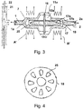
- FIG. 3 a valve arrangement is shown with a valve body 11 a, which encloses a valve control chamber 12 a, in which a closure body 17 is movably mounted.
- the closure body 17 has a magnetically active core 17a and a sheath 17b enclosing the core 17a, in particular made of a plastic, and is connected to a bearing disk 18.
- the bearing disc is in a view in the FIG. 4 shown. It is mounted on its circumference on the valve body 11a and overall elastic, so that it holds the closure body 17 in the illustrated center position.
- the bearing plate 18 has a plurality of openings 25, which allow the passage of the fluid to be controlled by the valve.
- FIG. 5 is shown in a three-dimensional view of the valve body 11a as a housing which encloses the valve control chamber 12a and the inflow channel 1 and the discharge channel 2, and the housing 16a containing the magnetic means A 'and B'.
- the housing 11a is, if a part of the valve device is to be used as a one-way valve, of the housing part 16a separable, so that the magnetic devices can be used repeatedly or further, while the part of the valve, which contains the valve control chamber 12a, can be replaced.
- FIG. 6 shows a solenoid valve with a transport channel, which is traversed by a fluid between an inflow opening 1 'and a drain opening 2'.
- a closure body 50 can be driven within the transport channel 88 between a first closure position and a second closure position, wherein in the first closure position, a first closure surface 51 closes a valve opening 51a, while in the second closure position, a closure surface 52 closes a valve opening 52a.
- the FIG. 8th 1 shows a catheter device 100 including a drive device with a rotatably drivable drive armature 66, which drives a rotating shaft 67 in a catheter 68.
- a catheter 68 Within the catheter 68, lumens, configured as an inflow channel 69 radially outward and a return flow channel 70 radially inward, are arranged concentrically with each other and with the outer sheath of the catheter.
- the inflow channel 69 and the return flow channel 70 are separated by a tubular partition 71.
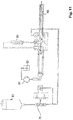
- FIG. 9 shows a structure similar to that FIG. 8th , wherein in addition to the valve 75 in front of the drive armature 66 and behind the peristaltic pump 72, a second valve 75 'is disposed between the return flow passage 70 and the return flow pump 80.
- FIG.8 In flushing systems is used in which no unwanted negative pressure in the return is generated by system components, it is possible FIG.9 can also be used in flushing systems in which an unwanted negative pressure is created in the return line (eg due to the winding direction of a flexible shaft). This negative pressure is detected by the sensor, which then ensures by closing the valve 75 'down that no medium from container 82 via the pump 81 comes into the rinse cycle.
- the separating device is thus arranged between two valves and also between two fluid conveying devices, of which at least one, in particular both, with respect to the conveying direction of the fluid can be switched to reverse the flow direction.
- a peristaltic pump 72 with a reservoir 83 which allows gravity flushing by flowing the fluid through the valve 75 and on to the catheter 68 by gravity.
- the rotating shaft 84 within the catheter 68 has, due to its stranded stranded strand-based construction, a coiled outer structure which gives it a pumping action in the direction away from the drive armature 66 even upon rotation.
- FIG. 11 shows a constellation similar to that FIG. 9 , wherein instead of the peristaltic pump 72, a gravity feed 83 is provided, wherein the fluid in normal operation from there via the valve into the catheter 68 and there first through the inflow 69 radially outward into the return flow channel 70 radially inside and from there to a peristaltic pump 81, the aspirates the fluid and directs it into the reservoir 82.
- the fluid first passes through the separating device 80, which is arranged between the return flow channel and the housing of the drive armature 66. Thereafter, the fluid flows past the drive armature 66 to the peristaltic pump 81.
- FIG. 12 shows a structure similar to the FIG. 9 , wherein a further separating device 80 'ensures that the function of the sealing surfaces of the valve 75' is not impaired by adhering particles.
Abstract
Die Erfindung bezieht sich auf eine Kathetervorrichtung (100), enthaltend einen Katheter (68) zum Einführen in ein Lebewesen sowie mindestens ein Lumen (69, 70, 74, 79) zum Führen eines Fluidflusses innerhalb eines Teils der Kathetervorrichtung sowie enthaltend ein Ventil zur Steuerung eines Fluidflusses insbesondere durch einen Katheter, mit einem Ventilsteuerraum (12, 12a), in dem ein Zuflusskanal (1) mit einer Zuflussöffnung (Ia) und ein Abflusskanal (2) mit einer Abflussöffnung (2a) münden, und mit einem in dem Ventilsteuerraum (12, 12a) gesteuert bewegbaren Verschlusselement (5, 13, 17), das in wenigstens einer ersten Stellung (I) die Abflussöffnung (2a), in wenigstens einer zweiten Stellung (II) die Zuflussöffnung (Ia) verschließt und das in wenigstens einer dritten Stellung (III) einen Verbindungskanal zwischen der Zuflussöffnung (Ia) und der Abflussöffnung (2a) offenhält, wobei ein Ventilantrieb (A, B, A', B', 3, 14, 18) vorgesehen ist, der das Verschlusselement (5, 13, 17) wahlweise wenigstens in die erste, zweite oder dritte Stellung bewegt, wobei das mindestens eine Lumen (69, 70, 74, 79) mit dem Zuflusskanal oder dem Abflusskanal fluidleitend verbunden ist.The invention relates to a catheter device (100) comprising a catheter (68) for introduction into a living being and at least one lumen (69, 70, 74, 79) for guiding fluid flow within a portion of the catheter device and containing a valve for control a fluid flow in particular through a catheter, with a valve control chamber (12, 12a), in which an inflow channel (1) with an inflow opening (Ia) and an outflow channel (2) with an outflow opening (2a) open, and with one in the valve control chamber (FIG. 12, 12a) controlled movable closure element (5, 13, 17) in at least a first position (I) the drain opening (2a), in at least one second position (II) closes the inflow opening (Ia) and in at least a third Position (III) a connecting channel between the inflow opening (Ia) and the drain opening (2a) holds open, wherein a valve drive (A, B, A ', B', 3, 14, 18) is provided which the closure element (5, 13, 17) selectively moves at least in the first, second or third position, wherein the at least one lumen (69, 70, 74, 79) is fluid-conductively connected to the inflow channel or the outflow channel.
Description
Die Erfindung liegt auf dem Gebiet der Mechanik und ist mit besonderem Vorteil auf dem Gebiet der Medizintechnik anwendbar. Sie befasst sich insbesondere mit einem Ventil, das auch bei unterschiedlichen Druckverhältnissen ein sicheres Sperren eines Fluidflusses durch einen Katheter erlaubt.The invention is in the field of mechanics and is applicable with particular advantage in the field of medical technology. In particular, it deals with a valve that allows a secure blocking of fluid flow through a catheter even under different pressure conditions.
Aus dem Stand der Technik sind zur Steuerung von Fluidflüssen vielfältige Absperrventile bekannt, Beispielsweise wird in der
Zudem ist für Anwendungen im Medizintechnikbereich eine einfache Reinigungs- und Sterilisationsmöglichkeit oder wahlweise eine einfache Austauschbarkeit wichtig, wenn Einwegbauteile verwendet werden.In addition, for applications in the medical technology field, a simple cleaning and sterilization option or optionally a simple interchangeability is important if disposable components are used.
Der vorliegenden Erfindung liegt vor dem Hintergrund des Standes der Technik somit die Aufgabe zugrunde, eine Kathetervorrichtung bzw. ein Ventil zu schaffen, das bei geringen Fluiddurchsätzen auch unter unterschiedlichen Druckverhältnissen ein sicheres Absperren und Öffnen eines Fluidkanals erlaubt.The present invention is therefore based on the background of the prior art, the task of providing a catheter device or a valve that allows for low fluid flow rates under different pressure conditions, a safe shut-off and opening a fluid channel.
Die Aufgabe wird mit den Merkmalen der Erfindung gemäß den Patentansprüchen gelöst. In den Unteransprüchen sind vorteilhafte Ausgestaltungen der Erfindung angegeben.The object is achieved with the features of the invention according to the claims. In the subclaims advantageous embodiments of the invention are given.
Dies betrifft zunächst eine Kathetervorrichtung, enthaltend einen Katheter zum Einführen in ein Lebewesen sowie mindestens ein Lumen zum Führen eines Fluidflusses innerhalb eines Teils der Kathetervorrichtung sowie enthaltend ein Ventil zur Steuerung eines Fluidflusses insbesondere durch einen Katheter, mit einem Ventilsteuerraum, in dem ein Zuflusskanal mit einer Zuflussöffnung und ein Abflusskanal mit einer Abflussöffnung münden, und mit einem in dem Ventilsteuerraum gesteuert bewegbaren Verschlusselement, das in wenigstens einer ersten Stellung die Abflussöffnung, in wenigstens einer zweiten Stellung die Zuflussöffnung verschließt und das in wenigstens einer dritten Stellung einen Verbindungskanal zwischen der Zuflussöffnung und der Abflussöffnung offenhält, wobei ein Ventilantrieb vorgesehen ist, der das Verschlusselement wahlweise wenigstens in die erste, zweite oder dritte Stellung bewegt, wobei das mindestens eine Lumen mit dem Zuflusskanal oder dem Abflusskanal fluidleitend verbunden ist.This relates first to a catheter device, comprising a catheter for insertion into a living being and at least one lumen for guiding a fluid flow within a part of the catheter device and containing a valve for controlling a fluid flow, in particular by a catheter, with a valve control chamber, in which an inflow channel with a Inlet opening and a drain channel with a drain opening open, and with a controllable in the valve control chamber closure element which closes the inlet opening in at least a first position, the inlet opening in at least one second position and in at least a third position a connecting channel between the inlet opening and the Outlet opening holds open, wherein a valve drive is provided which moves the closure element selectively at least in the first, second or third position, wherein the at least one lumen flui with the inflow channel or the outflow channel is connected conductively.
Wie weiter unten noch einmal näher ausgeführt wird, ist mit der Kathetervorrichtung eine sehr genaue Führung von Spülflüssigkeit, sowohl in Hinblick auf die Spülrichtung als auch in Hinblick auf die Spülvolumina und Spülflüsse in den Kathetern möglich. Dies geschieht insbesondere vor dem Hintergrund von biegsamen drehbaren Wellen, die besondere Sogwirkung bzw. wechselnde Druckverhältnisse, je nach Länge und Einbauort, aufweisen. Im Übrigen ist gerade auf diesem Gebiet der Medizintechnik eine einwandfreie Funktion der Ventile von größter Wichtigkeit. Insbesondere ist auch die Kopplung mit einer Separiereinrichtung zum Entfernen von Verschmutzungen und Abrieb, beispielsweise Metallabrieb, aus der Spülflüssigkeit steuerbar. Dies kann beispielsweise der Fall sein, wenn bei einem "Durchspülen" einer Separiereinrichtung (also einer Einrichtung zum Auffangen/Einfangen von Abrieb etc.) eine temporäre Richtungsumkehr zur Reinigung sinnvoll ist.As will be explained in more detail below, with the catheter device a very precise guidance of irrigation fluid is possible both with regard to the irrigation direction and with regard to the irrigation volumes and irrigation flows in the catheters. This happens in particular against the background of flexible rotatable shafts, which have special suction effect or changing pressure conditions, depending on the length and installation location. Incidentally, a perfect function of the valves is of the utmost importance especially in this field of medical technology. In particular, the coupling with a separating device for removing contaminants and abrasion, for example metal abrasion, can be controlled from the rinsing liquid. This may be the case, for example, if a "reversal" of a separating device (that is to say a device for catching / capturing abrasion, etc.) makes a temporary reversal of direction for cleaning meaningful.
Beispiele für eine derartige Separiereinrichtung sind beispielsweise in der parallelen, tagesgleich eingereichten ECP 46 PCT (Aktenzeichen noch nicht bekannt) der ECP GmbH erläutert. Desweiteren wird die Priorität der beiden Voranmeldungen
Eine Ausführungsform sieht vor, dass der Katheter eine drehbare Welle aufweist. Diese ist beispielsweise flexibel, insbesondere derart flexibel, dass sie an eine Krümmung eines menschlichen Aortenbogens anpassbar ist, also dass beispielsweise bei einem Einführen einer entsprechenden Welle in die Femoralarterie und einem Weiterführen entlang der Aorta ein Pumpenkopf an der Spitze der flexiblen Welle in den Ventrikel des Herzens eingeführt wird und sich bei einem Schieben des Katheters in Richtung der aufsteigenden Aorta der Katheter selbsttätig der Krümmung des Aortenbogens anpasst.One embodiment provides that the catheter has a rotatable shaft. This is for example flexible, in particular so flexible that it is adaptable to a curvature of a human aortic arch, that is, for example, when inserting a corresponding shaft into the femoral artery and continuing along the aorta, a pump head at the tip of the flexible shaft into the ventricle of the Heart is introduced and automatically adjusts to the curvature of the aortic arch when pushing the catheter in the direction of the ascending aorta of the catheter.
In einer Ausführungsform ist die Antriebseinrichtung außerhalb des Lebewesens (also außerhalb der Femoralarterie im obigen Beispiel) gewählt, die drehbare Welle läuft in die Femoralarterie hinein bis beispielsweise in den linken Ventrikel zum Antrieb eines dort positionierten Pumpenkopfes einer Katheterpumpe (Herzpumpe).In one embodiment, the drive means is selected outside the living organism (ie outside the femoral artery in the above example), the rotatable shaft runs into the femoral artery into, for example, the left ventricle for driving a pump head of a catheter pump (heart pump) positioned there.
Eine weitere Ausführungsform sieht vor, dass der Katheter mehr als ein Lumen aufweist, wobei mindestens ein Lumen für die Fluidführung in distaler Richtung und mindestens ein Lumen für die Fluidführung in proximaler Richtung ausgeführt ist.A further embodiment provides that the catheter has more than one lumen, wherein at least one lumen for the fluid guide in the distal direction and at least one lumen for the fluid guide in the proximal direction is executed.
In einer Ausführungsform können zwischen 10 und 90 Prozent des in distaler Richtung geführten, in einem ersten Lumen geführten Fluidstroms in einem anderen Lumen in proximaler Richtung rückgeführt werden. Bei der sogenannten "Y-Spülung" wird also ein Fluidstrom in distaler Richtung gefördert, ein Teil der Spülflüssigkeit gelangt beispielsweise in das Herz am distalen Ende des Katheters, ein anderer Teil der Spülflüssigkeit tritt durch das jeweils andere Lumen dann wieder aus. Es sind auch noch komplexere Ausführungsformen möglich, bei denen zusätzlich auch noch die Antriebseinrichtung (d. h. der Antrieb, der beispielsweise außerhalb des Körpers befindlich ist) mit einem Fluidstrom versorgt wird, um beispielsweise Abrieb im Bereich der Lager etc. aus der Kathetervorrichtung zu entfernen.In one embodiment, between 10 and 90 percent of the distally directed fluid flow in a first lumen may be recirculated in another lumen in the proximal direction. In the so-called "Y-flushing", therefore, a fluid flow is conveyed in the distal direction, a part of the flushing fluid passes, for example, into the heart at the distal end of the catheter, and another part of the flushing fluid then exits through the respective other lumen. Even more complex embodiments are possible in which, in addition, the drive device (that is to say the drive which is located, for example, outside the body) is supplied with a fluid flow in order to remove, for example, abrasion in the region of the bearings etc. from the catheter device.
Daher sehen Ausführungsformen auch vor, dass ein, zwei, drei oder auch mehr Ventile vorgesehen sind, um beispielsweise komplexere Spülvorgänge bzw. bewusste Umkehrungen der Spülrichtung (beispielsweise zur Reinigung einer Separiereinrichtung) durchzuführen.Therefore, embodiments also provide that one, two, three or more valves are provided to perform, for example, more complex flushing operations or deliberate reversals of the flushing direction (for example, for cleaning a separating device).
Eine Ausführungsform sieht vor, dass mehrere Ventile, beispielsweise zwei Ventile, vorgesehen sind, wobei der Abfluss des ersten Ventils mit einem Zufluss zur Antriebseinrichtung der Kathetervorrichtung verbunden ist und ein zweites Ventil vorhanden ist, wobei der Zufluss des zweiten Ventils mit einem in proximaler Richtung fluidführenden Lumen des Katheters verbunden ist.An embodiment provides that a plurality of valves, for example two valves, are provided, wherein the outflow of the first valve is connected to an inlet to the drive device of the catheter device and a second valve is present, wherein the inflow of the second valve with a fluid in the proximal direction Lumen of the catheter is connected.
Verschiedene Ausführungsformen der Ventile in einer Kathetervorrichtung 100 werden im speziellen Beschreibungsteil gezeigt. Dies betrifft beispielsweise die Ausführungsformen 8, 9, 10, 11 und 12.Various embodiments of the valves in a catheter device 100 are shown in the specific part of the description. This applies, for example, to
Es sei außerdem erwähnt, dass die Ventile so ausgeführt sind, dass ein Ventilantrieb des Verschlusselementes separierbar ist, d. h. werkzeugfrei trennbar von dem Rest der Anordnung, vor allem um einen leichteren Austausch zu ermöglichen und die Sterilität zu geringen Kosten auch bei einer Mehrfachverwendung von Teilen der Anordnung sicherzustellen.It should also be mentioned that the valves are designed so that a valve drive of the closure element is separable, ie tool-free separable from the rest of the arrangement, especially to allow easier replacement and to ensure sterility at a low cost, even with multiple use of parts of the assembly.
Es sei außerdem ergänzt, dass der Ventilantrieb auf beliebige Weisen erfolgen kann. Neben magnetisch wirkenden Antrieben kann der Antrieb auch rein mechanisch erfolgen, er kann elektrisch erfolgen oder auch induktiv; hier sind jegliche Antriebe möglich, die es einem Fachmann erlauben, eine Bewegung eines Verschlusselementes in die erste, zweite und/oder dritte Stellung zu erreichen.It should also be added that the valve drive can be done in any way. In addition to magnetically acting drives, the drive can also be purely mechanical, it can be done electrically or inductively; Here are any drives possible that allow a professional to achieve a movement of a closure element in the first, second and / or third position.
Die Anmeldung bezieht sich unter anderem auf ein Ventil zur Steuerung eines Fluidflusses durch einen Katheter, mit einem Ventilsteuerraum, in dem ein Zuflusskanal mit einer Zuflussöffnung und ein Abflusskanal mit einer Abflussöffnung münden, und mit einem in dem Ventilsteuerraum gesteuert bewegbaren Verschlusselement, das in wenigstens einer ersten Stellung die Abflussöffnung, in wenigstens einer zweiten Stellung die Zuflussöffnung verschließt und das in wenigstens einer dritten Stellung einen Verbindungskanal zwischen der Zuflussöffnung und der Abflussöffnung offenhält, wobei ein Ventilantrieb vorgesehen ist, der das Verschlusselement wahlweise wenigstens in die erste, zweite oder dritte Stellung bewegt. In der dritten oder weiteren Ventilstellungen können in einer Ausgestaltung verschiedene Ventilspaltgrößen zur Steuerung eines Durchflusses ansteuerbar sein.The application relates, inter alia, to a valve for controlling a flow of fluid through a catheter, having a valve control space in which an inflow channel with an inflow opening and a outflow channel with an outflow opening, and with a controlled in the valve control chamber movable closure element which in at least one first position the drain opening, in at least one second position closes the inlet opening and holds open in at least a third position a connecting channel between the inlet opening and the drain opening, wherein a valve drive is provided which moves the closure element selectively at least in the first, second or third position , In one embodiment, in the third or further valve positions, different valve gap sizes can be controlled to control a flow.
Durch die Konstruktion kann das Ventil den Fluiddurchfluss sowohl durch Verschließen der Abflussöffnung als auch Verschließen der Zuflussöffnung sperren. Die Begriffe Zuflusskanal und Abflusskanal sind so gewählt, dass der Zuflusskanal mit seiner Mündung den Kanal bezeichnet, der unter normalen oder statistisch häufigsten Bedingungen und Druckverhältnissen als Zuflusskanal fungiert. Analog verhält es sich mit dem Begriff Abflusskanal.The design allows the valve to block fluid flow both by closing the drain port and closing the inlet port. The terms inflow channel and outflow channel are chosen so that the inflow channel with its mouth designates the channel which acts as an inflow channel under normal or statistically most frequent conditions and pressure conditions. The same applies to the term drainage channel.
Damit ergibt sich sowohl bei einem höheren Druck im Zuflusskanal als im Abflusskanal als auch bei einem höheren Druck im Abflusskanal als im Zuflusskanal jeweils die Möglichkeit, durch den Druckunterschied die Schließkräfte und damit den dichten Sitz des Verschlusskörpers zu unterstützen, indem bei einem Überdruck im Zuflusskanal der Verschlusskörper die Abflussöffnung verschließt, während bei einem Überdruck im Abflusskanal der Verschlusskörper die Zuflussöffnung verschließt. In jedem dieser Fälle wird durch den Druckunterschied zwischen dem Ventilsteuerraum und dem jeweils verschlossenen Kanal der Verschlusskörper zusätzlich zu den mechanischen Antriebskräften in der Verschlussstellung gehalten.Thus, both at a higher pressure in the inflow channel than in the outflow channel and at a higher pressure in the outflow channel than in the inflow channel, respectively, it is possible to support the closing forces and thus the tight seat of the closure body by means of the pressure difference, by providing overpressure in the inflow channel Closing body closes the drain opening, while at an overpressure in the drainage channel of the Closing body closes the inlet opening. In each of these cases, the closure body is held in the closed position in addition to the mechanical drive forces by the pressure difference between the valve control chamber and the respective closed channel.
Da der Zuflusskanal in bestimmten Fällen als Abflusskanal fungieren kann und umgekehrt, könnte auch einfach der Zuflusskanal als erster Kanal und der Abflusskanal als zweiter Kanal bezeichnet werden.Since the inflow channel can act as a drain channel in certain cases and vice versa, could also simply the inflow channel as the first channel and the outflow channel are referred to as the second channel.
Die zuverlässige Dichtung ist insbesondere in solchen System wichtig, in denen wechselnde oder sich langfristig ändernde Druckverhältnisse herrschen können. Solche Verhältnisse herrschen beispielsweise in Kathetern, die zur Führung von mechanisch antreibbaren rotierenden Wellen und/oder zum Spülen derartiger Katheter verwendet werden. Üblicherweise wird beim Spülen von Kathetern, die eine rotierende Welle führen, ein sehr geringer Flüssigkeitsdurchsatz angestrebt, der unter anderem dazu führt, dass Abriebpartikel der Welle nur in eine definierte Richtung weiterbewegt werden. Derartige rotierende Wellen werden oft aus einem Bündel verseilter Drähte hergestellt, wobei das Bündel an seiner Außenkontur eine Wendelform aufweist. Diese Wendelform bewirkt bei schneller Rotation der Welle eine Förderwirkung der die Welle umgebenden Spülflüssigkeit, so dass zu der eigentlichen Umlaufbewegung der Spülflüssigkeit, die durch eine Spülmittelpumpe bewirkt wird, eine zusätzliche Sogwirkung hinzutritt. Diese Sogwirkung ist zeitlich veränderlich, da die Kontur der Welle sich durch Abnutzung und Abrieb mit der Zeit verändert. Hierdurch treten in entsprechenden Spülkathetern auch veränderliche Druckverhältnisse auf, die bis zu einer Umkehrung des Spülmittelflusses führen können. Dabei wird bei einem erfindungsgemäßen Ventil angestrebt, die Möglichkeit einer sicheren Sperrung/Steuerung eines derartigen Fluidflusses unabhängig von den Druckverhältnissen zu erreichen. Wie oben ausgeführt, ergibt sich dabei die Möglichkeit, je nach Druckgefälle einen Verschluss des entsprechenden Fluidkanals durch wahlweises Verschließen der Zuflussöffnung oder der Abschlussöffnung (oder: erste Öffnung oder zweite Öffnung) zu erreichen, wobei die jeweils verschlossene Öffnung danach ausgewählt werden kann, in welcher Position die Verschlussstellung des Verschlusselementes an der Öffnung durch das Druckgefälle stabilisiert wird.The reliable seal is particularly important in those systems in which changing or long-term changing pressure conditions can prevail. Such conditions prevail, for example, in catheters which are used to guide mechanically driven rotating shafts and / or for flushing such catheters. Usually, when rinsing catheters that guide a rotating shaft, a very low fluid throughput is sought, which, inter alia, causes abrasion particles of the shaft to be moved only in a defined direction. Such rotating shafts are often made from a bundle of stranded wires, the bundle having a helical shape on its outer contour. This helical shape causes during rapid rotation of the shaft, a conveying action of the washing liquid surrounding the shaft, so that added to the actual circulation movement of the washing liquid, which is caused by a detergent pump, an additional suction effect. This suction effect is variable over time, since the contour of the shaft changes over time due to wear and abrasion. As a result, variable pressure conditions also occur in corresponding flush catheters, which can lead to a reversal of the flushing agent flow. In the case of a valve according to the invention, the aim is to achieve the possibility of a secure blocking / control of such a fluid flow independently of the pressure conditions. As stated above, it is possible, depending on the pressure gradient, to achieve a closure of the corresponding fluid channel by selectively closing the inflow orifice (or: first or second orifice), the respective closed orifice being selectable thereafter, in which Position the closed position of the closure element is stabilized at the opening by the pressure gradient.
Ausgestaltungen sehen vor, dass zumindest Teile des Ventils als Einwegbauteile konzipiert sind. Dies ist beispielsweise für den Bereich der Medizintechnik sinnvoll. Auf diese Weise können fluidleitende Bauteile (beispielsweise der Ventilsteuerraum) als Einwegbauteile austauschbar sein. Kostenträchtige Bauteile, wie z. B. der Ventilantrieb des Verschlusselements, die vorzugsweise nicht unmittelbar mit dem Fluid in Berührung kommen, sind als wiederverwertbare Bauteile vorgesehen. So ist es beispielsweise möglich, dass der Ventilsteuerraum Teil eines Katheters, insbesondere eines Katheterschlauches aus beispielsweise Kunststoffmaterial, ist. Als Ventilantriebe kommen beispielsweise Systeme in Betracht, die berührungsfrei (z. B. magnetisch, induktiv) arbeiten oder elastische Eigenschaften z. B. des Ventilsteuerraums ausnutzen, um Antriebskräfte zu übertragen.Embodiments provide that at least parts of the valve are designed as disposable components. This is useful, for example, in the field of medical technology. In this way, fluid-conducting components (for example the valve control chamber) can be exchangeable as disposable components. Costly components, such. As the valve drive of the closure element, which preferably does not come into direct contact with the fluid are provided as reusable components. For example, it is possible for the valve control chamber to be part of a catheter, in particular a catheter tube of, for example, plastic material. Suitable valve actuators are, for example, systems which operate without contact (eg magnetically, inductively) or have elastic properties, for example. B. the valve control room to transfer driving forces.
Eine Ausgestaltung sieht vor, dass die dritte Stellung des Verschlusselementes zwischen der ersten und der zweiten Stellung liegt.One embodiment provides that the third position of the closure element lies between the first and the second position.
Dies bewirkt, dass aus jeder der Verschlussstellungen durch eine minimale Bewegung des Verschlusselementes ein Freimachen des Fluidkanals ermöglicht ist und dass aus der dritten Stellung jede der beiden Verschlussstellungen schnell, sicher und durch eine minimale Bewegung des Verschlusselementes erreichbar ist.This causes a free movement of the fluid channel is made possible from each of the closure positions by a minimal movement of the closure element and that from the third position, each of the two closure positions can be reached quickly, safely and by a minimal movement of the closure element.
Weiter kann vorgesehen sein, dass der Ventilsteuerraum mit Ausnahme der Zuflussöffnung und der Abflussöffnung allseits fluiddicht abgeschlossen ist.It can further be provided that the valve control chamber, with the exception of the inflow opening and the outflow opening, is closed on all sides in a fluid-tight manner.
Diese Konstruktion bewirkt eine vollständige Medientrennung, so dass die Elemente des Ventilantriebs nicht mit dem eigentlich zu steuernden Fluid in Verbindung kommen.This design provides complete media separation so that the elements of the valve drive do not communicate with the actual fluid to be controlled.
Beispielsweise kann dies dadurch erreicht werden, dass das Verschlusselement eine bewegliche Membran aufweist, die den Ventilsteuerraum fluiddicht abschließt und derart auslenkbar ist, dass wahlweise die Zuflussöffnung oder die Abflussöffnung durch Teile der Membran verschließbar sind.For example, this can be achieved in that the closure element has a movable membrane which closes off the valve control chamber in a fluid-tight manner and can be deflected such that either the inflow opening or the outflow opening can be closed by parts of the membrane.
Im unausgelenkten Zustand bildet die Membran, die umlaufend fluiddicht mit den übrigen Teilen des Ventilsteuerraums verbunden, insbesondere verklebt oder verschweißt ist, einen Abschluss des Ventilsteuerraums. Das zu steuernde Fluid kann an der Membran vorbei zwischen der Zuflussöffnung und der Abflussöffnung oder umgekehrt strömen. Die Membran ist dabei elastisch oder plastisch verformbar ausgeführt, so dass sie auslenkbar ist, und zwar so weit, dass sie oder ein Teil von ihr wahlweise vor eine der beiden Öffnungen, die Zuflussöffnung oder die Abflussöffnung, bringbar und gegen diese Öffnung pressbar ist. Hierdurch wird ein Abschließen der Zuflussöffnung oder der Abflussöffnung erreicht. Zum Öffnen der jeweiligen Zufluss- oder Abflussöffnung wird die Membran entspannt, so dass sie sich im Idealfall von selbst oder durch ihre Eigenspannung in ihre Ausgangslage bewegt.In the undeflected state, the membrane, which is circumferentially fluid-tightly connected to the remaining parts of the valve control chamber, in particular adhesively bonded or welded, forms a closure of the valve control chamber. The fluid to be controlled can flow past the membrane between the inlet opening and the outlet opening or vice versa. The membrane is designed to be elastically or plastically deformable, so that it is deflectable, to the extent that it or a part of it either in front of one of the two openings, the inlet opening or the drain opening, can be brought and pressed against this opening. As a result, a completion of the inflow opening or the discharge opening is achieved. To open the respective inflow or outflow, the membrane is relaxed, so that it moves in the ideal case by itself or by their residual stress in their initial position.
Eine vorteilhafte Ausgestaltung der Erfindung sieht hierzu vor, dass ein Antriebshebel des Ventilsantriebs die Membran wenigstens in der ersten und zweiten Stellung auslenkt.An advantageous embodiment of the invention provides for this purpose that a drive lever of the valve drive deflects the membrane at least in the first and second positions.
Der Antriebshebel greift somit unter die Membran und lenkt diese so weit aus, dass sie zwischen der Zuflussöffnung bzw. der Abflussöffnung und dem Antriebshebel eingeklemmt wird und die jeweilige Öffnung verschließt. Wird der Antriebshebel des Ventilantriebs zurückbewegt, so löst sich die Membran von der jeweiligen Öffnung wieder.The drive lever thus engages under the membrane and deflects it so far that it is trapped between the inlet opening or the discharge opening and the drive lever and closes the respective opening. If the drive lever of the valve drive is moved back, the membrane is released from the respective opening.
Der Antriebshebel kann dabei an seinem gegen die Membran drückenden Ende beispielsweise eine Kugel- oder Ellipsoidform aufweisen, die besonders gut zum Verschluss einer Öffnung im Ventilsteuerraum unter Zwischenlage der Membran geeignet ist.The drive lever may have, for example, at its oppressive against the membrane end a spherical or Ellipsoidform, which is particularly well suited for closing an opening in the valve control chamber with the interposition of the membrane.
Eine weitere vorteilhafte Ausgestaltung der Erfindung kann vorsehen, dass das Verschlusselement durch einen magnetisch wirkenden Ventilantrieb antreibbar ist.A further advantageous embodiment of the invention can provide that the closure element can be driven by a magnetically acting valve drive.
Beispielsweise durch eine derartige Gestaltung des Ventilantriebs wird es möglich, das Ventil selbst von der Antriebseinheit vollständig zu trennen, beispielsweise dadurch, dass der Ventilsteuerraum von dem magnetischen Antrieb durch eine gas- oder fluidundurchlässige Wand getrennt ist. Auch der gesamte den Ventilsteuerraum umgebende Ventilkörper kann nochmals durch eine zusätzliche medientrennende Wand von den Elementen getrennt sein, die die Magnetfelder für den Antrieb erzeugen.For example, such a design of the valve drive, it is possible to completely separate the valve itself from the drive unit, for example, characterized in that the valve control chamber is separated from the magnetic drive by a gas or fluid-impermeable wall. Also the Whole valve body surrounding the valve control chamber can be separated again by an additional media-separating wall of the elements that generate the magnetic fields for the drive.
Beispielsweise kann der vom Ventilsteuerraum abgewandte Teil des Antriebshebels magnetisch ausgestaltet und durch einen externen Magneten auslenkbar sein.For example, the remote from the valve control chamber part of the drive lever can be designed magnetically and be deflected by an external magnet.
Die Erfindung kann zudem vorteilhaft dadurch ausgestaltet werden, dass das in dem Ventilsteuerraum angeordnete Verschlusselement magnetisch aktiv ist und mit einem Magnetfeld des Ventilantriebs wechselwirkt.The invention can also advantageously be configured in that the closure element arranged in the valve control chamber is magnetically active and interacts with a magnetic field of the valve drive.
In diesem Fall kann das Verschlusselement oder ein Teil des Verschlusselementes aus einem Magnetkörper bestehen, der beispielsweise magnetisiert sein kann oder der zumindest aus einem ferromagnetischen Stoff bestehen kann und der im Feld eines externen Magneten antreibbar ist. In diesem Fall kann der magnetisch aktive Teil des Verschlusselementes mit einer nicht magnetisch aktiven fluidundurchlässigen Schicht abgedeckt sein, so dass das Fluid, dessen Durchfluss durch das Ventil gesteuert werden soll, mit dem magnetisch aktiven Teil nicht in Berührung kommt.In this case, the closure element or a part of the closure element may consist of a magnetic body, which may be magnetized, for example, or which may consist of at least one ferromagnetic material and which is drivable in the field of an external magnet. In this case, the magnetically active part of the closure element may be covered with a non-magnetically active fluid-impermeable layer, so that the fluid whose flow is to be controlled by the valve does not come into contact with the magnetically active part.
Eine weitere vorteilhafte Ausgestaltung sieht vor, dass sowohl der Ventilsteuerraum als auch die mit dem Verschlusselement mechanisch verbundenen Teile des Ventilantriebs mit Ausnahme der Zufluss- und Abflussöffnung fluiddicht abgeschlossen und insbesondere von einer Magnetfelderzeugungseinrichtung des Ventilantriebs separierbar sind.A further advantageous embodiment provides that both the valve control chamber and the parts of the valve drive that are mechanically connected to the closure element are fluid-tight with the exception of the inflow and outflow openings and in particular are separable from a magnetic field generating device of the valve drive.
Durch diese Ausgestaltung ist es beispielsweise mit geringem Aufwand möglich, einen Teil des Ventils, der den Ventilsteuerraum und ggf. einen Verschlusskörper oder Teile des Verschlusskörpers enthält, von der Magnetfelderzeugungseinrichtung zu separieren (das heißt vorzugsweise zu trennen / zerstörungsfrei abzukoppeln) und als Einweg-Bauteil zu ersetzen. Die Magnetfelderzeugungseinrichtung kann ihrerseits dann mehrfach verwendet werden. Eine weitere vorteilhafte Ausgestaltung der Erfindung sieht vor, dass das Verschlusselement durch ein elastisches Federelement vorzugsweise in die dritte Stellung bewegt wird.With this configuration, it is possible, for example, with little effort, to separate a part of the valve, which contains the valve control chamber and possibly a closure body or parts of the closure body of the magnetic field generating device (that is, preferably to separate / decouple non-destructive) and as a disposable component to replace. The magnetic field generating device can then be used several times in turn. A further advantageous embodiment of the invention provides that the closure element is preferably moved by an elastic spring element in the third position.
Das Verschlusselement kann durch das elastische Federelement, beispielsweise eine Schraubenfeder, in der dritten Stellung gehalten und gegen die Kraft der Feder durch einen Antrieb in die erste oder zweite Stellung gebracht werden. Nach Abschalten des Ventilantriebs ist vorgesehen, dass das elastische Federelement das Verschlusselement selbstständig wieder in die dritte Stellung bewegt, Auf diese Weise ist erreicht, dass bei einem Ausfall der elektrischen Versorgung, sofern Elektromagnete für den Antrieb verwendet werden, das Verschlusselement keiner äußeren Krafteinwirkung unterliegt und somit das Ventil im geöffneten Zustand stehenbleibt. Zudem wird durch das elastische Federelement das Lösen des Verschlusselementes aus der ersten Stellung und der zweiten Stellung unterstützt.The closure element can be held in the third position by the elastic spring element, for example a helical spring, and brought by a drive into the first or second position against the force of the spring. After switching off the valve drive is provided that the elastic spring element automatically moves the closure element back to the third position, in this way it is achieved that in case of failure of the electrical supply, if electromagnets are used for the drive, the closure element is not subject to external force and Thus, the valve stops in the open state. In addition, the release of the closure element from the first position and the second position is supported by the elastic spring element.
Die Erfindung kann zudem vorteilhaft dadurch ausgestaltet werden, dass unmittelbar am Ventilsteuerraum, insbesondere im Inneren des Verschlusselements ein Magnet als Teil einer Separiereinrichtung vorgesehen ist. In diesem Fall können im Ventilsteuerraum magnetische und magnetisierbare Partikel von dem Magnet der Separiereinrichtung gebunden werden, so dass sie von den Dichtflächen des Ventils ferngehalten werden. Dabei kann insbesondere vorgesehen sein, dass der/die Magnet(e) von Antriebsankern des einen Ventilantriebs separat, insbesondere beabstandet, vorgesehen sind.The invention can also advantageously be configured in that directly on the valve control chamber, in particular in the interior of the closure element, a magnet is provided as part of a separating device. In this case, magnetic and magnetizable particles can be bound by the magnet of the separating device in the valve control chamber, so that they are kept away from the sealing surfaces of the valve. It may be provided in particular that the / the magnet (s) of drive armatures of a valve drive separately, in particular spaced apart, are provided.
Es kann allerdings auch vorgesehen sein, dass der Magnet der Separiereinrichtung mit einem oder mehreren Magneten des Ventilantriebs kombiniert oder verbunden ist, oder eine erste Funktionsfläche eines Magneten kann der Separierung von Partikeln dienen, während andere Funktionsflächen der Ventilfunktion dienen.However, it can also be provided that the magnet of the separating device is combined or connected with one or more magnets of the valve drive, or a first functional surface of a magnet can serve to separate particles, while other functional surfaces serve the valve function.
Die Erfindung kann sich zudem auf eine Schutzeinrichtung für ein Ventil beziehen, das mit einem strömenden Fluid in Verbindung steht, dadurch gekennzeichnet, dass entlang eines Strömungskanals für das Fluid, insbesondere eines Katheters, von dem Ventil beabstandet und insbesondere von diesem separiert eine Separiereinrichtung zur Rückhaltung von im Fluid befindlichen Partikeln mit wenigstens einem Magnetelement vorgesehen ist.The invention may also relate to a protective device for a valve, which communicates with a flowing fluid, characterized in that along a flow channel for the fluid, in particular a catheter, spaced from the valve and in particular of this separating a separating device for the retention of particles in the fluid is provided with at least one magnetic element.
Die Separiereinrichtung kann vorteilhaft bezüglich der vorherrschenden Strömungsrichtung des Fluids stromaufwärts von dem Ventil vorgesehen sein, jedoch können die beiden genannten Elemente auch einfach hintereinander, insbesondere voneinander beabstandet, beispielsweise auch baulich voneinander getrennt, zum Beispiel in Form von zwei separaten Bauelementen mit verschiedenen Gehäusen, vorgesehen sein.The separating device may be advantageously provided with respect to the prevailing flow direction of the fluid upstream of the valve, but the two said elements may also be simply behind each other, in particular spaced from each other, for example, structurally separated, for example in the form of two separate components with different housings his.
Das Ventil kann frei von magnetischen oder magnetisch wirkenden Elementen sein und beispielsweise insgesamt unmagnetisch sein. Es kann eine Dichtfläche aufweisen, die vor Partikeln geschützt werden soll.The valve may be free of magnetic or magnetic elements and, for example, be nonmagnetic as a whole. It can have a sealing surface which is to be protected from particles.
Das Ventil kann auch magnetische Bauteile enthalten, wie beispielsweise einen Antriebsmagneten oder einen Anker. Das Magnetelement der Separiereinrichtung kann ein von den magnetischen Bauteilen des Ventils getrennter Magnet sein oder eine Funktionsfläche eines magnetischen Bauelementes, die ausschließlich die Funktion der Partikelseparation hat, wobei andere Funktionsflächen des magnetischen Bauelementes andere Funktionen des Ventils wie beispielsweise eine Antriebsfunktion ausüben können. In diesem letztgenannten Fall kann das Magnetelement der Separiereinrichtung mit einem magnetischen Bauelement des Ventils kombiniert, mit diesem zusammengefügt, zusammengefasst und insbesondere auch in einem Gehäuse zusammengefasst sein.The valve may also include magnetic components, such as a drive magnet or an armature. The magnetic element of the separating device may be a separate from the magnetic components of the valve magnet or a functional surface of a magnetic component having only the function of particle separation, wherein other functional surfaces of the magnetic component can perform other functions of the valve such as a drive function. In this latter case, the magnetic element of the separating device can be combined with a magnetic component of the valve, joined together, summarized and in particular also combined in a housing.
Die Funktionsfläche der Separiereinrichtung kann somit Partikel, insbesondere magnetische und/oder magnetisierbare Partikel einfangen und binden, bevor sie zu dem Ventil gelangen und somit die Ventilfunktion, beispielweise die Dichtfunktion der Dichtflächen, beeinträchtigen können.The functional surface of the separating device can thus capture and bind particles, in particular magnetic and / or magnetizable particles, before they can reach the valve and thus impair the valve function, for example the sealing function of the sealing surfaces.
Im Folgenden wird die Erfindung anhand von Ausführungsbeispielen in Figuren einer Zeichnung gezeigt und nachfolgend erläutert.In the following the invention will be shown by means of embodiments in figures of a drawing and explained below.
Dabei zeigen:
- FIG. 1
- eine erste Ausführungsform eines Ventils mit einem magnetischen Ventilantrieb im Querschnitt schematisch,
- FIG. 2
- die Ventilanordnung aus der
FIG. 1 in einer dreidimensionalen Ansicht, - FIG. 3
- in einem schematischen Schnitt eine zweite Ausführungsform des erfindungsgemäßen Ventils,
- FIG. 4
- eine Ansicht eines elastischen Federelementes,
- FIG. 5
- eine dreidimensionale Ansicht der Ventilanordnung aus der
FIG. 3 , - FIG. 6
- ein Ventil, das mit einer Separiereinrichtung verbunden ist,
- FIG. 7
- ein weiteres mit einer Separiereinrichtung verbundenes Ventil,
- FIG. 8
- eine Antriebseinheit für ein Funktionselement, das mittels einer in einem Katheter rotierenden Welle antreibbar ist,
- FIG. 9
- eine Abwandlung einer Antriebseinheit nach
FIG. 8 , - FIG. 10 und FIG. 11
- jeweils weitere Gestaltungsformen von Antriebseinrichtungen für in einem Katheter rotierende Wellen sowie
- FIG. 12
- eine Abwandlung einer Antriebseinheit nach
FIG. 9 .
- FIG. 1
- a first embodiment of a valve with a magnetic valve drive in cross-section schematically,
- FIG. 2
- the valve assembly of the
FIG. 1 in a three-dimensional view, - FIG. 3
- in a schematic section a second embodiment of the valve according to the invention,
- FIG. 4
- a view of an elastic spring element,
- FIG. 5
- a three-dimensional view of the valve assembly of the
FIG. 3 . - FIG. 6
- a valve connected to a separating device,
- FIG. 7
- another valve connected to a separating device,
- FIG. 8th
- a drive unit for a functional element, which can be driven by means of a shaft rotating in a catheter,
- FIG. 9
- a modification of a drive unit according to
FIG. 8th . - FIG. 10 and FIG. 11
- each further embodiments of drive means for rotating in a catheter waves and
- FIG. 12
- a modification of a drive unit according to
FIG. 9 ,
Die
Der Antriebshebel 3 ist um eine Welle 7, die mit Abstandshülsen 8 im Antriebsgehäuse 6 gelagert ist, schwenkbar. Der Antriebshebel 3 ist einmal durchgezogen in der dritten Stellung III dargestellt, in der er einen Verbindungskanal zwischen der Zuflussöffnung 1a und der Abflussöffnung 2a offen lässt, sowie gestrichelt in einer ersten Stellung I, in der das kugelförmige Ende 13 mittels der Membran 5 die Abflussöffnung 2a verschließt, und ebenso gestrichelt in einer zweiten Stellung II, in der der Antriebshebel mittels der Membran 5 die Zuflussöffnung 1a verschließt.The
In dem Antriebsgehäuse 6 ist im unteren Teil das elastische Federelement 10 als Schraubenfeder dargestellt, die das der Membran abgewandte Ende des Antriebhebels 3 mit dem Boden des Gehäuses 6 verbindet und somit den Antriebshebel in der dritten Stellung III hält.In the drive housing 6, the
Beiderseits des Antriebsgehäuses 6 sind zwei Elektromagneten A, B dargestellt, die, wenn sie mit einem Strom beaufschlagt werden, ein Magnetfeld erzeugen, das auf den unteren Teil 14 des Antriebshebels 3 wirkt und diesen je nach Richtung der magnetischen Kräfte in die erste Stellung I oder in die zweite Stellung II bewegt. Der untere Teil 14 des Antriebshebels 3 ist zu diesem Zweck magnetisch aktiv ausgebildet, entweder als ferromagnetisches, magnetisierbares oder als magnetisiertes Bauteil.On both sides of the drive housing 6, two electromagnets A, B are shown, which, when they are energized, generate a magnetic field which acts on the
Die
In der
Die Enden 19, 20 des Verschlusskörpers 17 sind derart geformt und gestaltet, dass sie die Zuflussöffnung 1a bzw. die Abflussöffnung 2a bei entsprechender Auslenkung des Verschlusskörpers 17 und federnder Verformung der Lagerscheibe 18 verschließen können.The ends 19, 20 of the
Zu diesem Zweck kann die Umhüllung 17b des Verschlusskörpers 17 beispielsweise aus einem elastischen Stoff, insbesondere einem Elastomer, bestehen. Der magnetische Kern 17a des Verschlusskörpers 17 ist durch die Magneteinrichtungen A', B' mit einer Kraft beaufschlagbar, die den Verschlusskörper 17 entweder in Richtung der Zuflussöffnung 1a oder in Richtung der Abflussöffnung 2a zieht, um das Ventil in die erste oder zweite Verschlussstellung zu bringen.For this purpose, the
In der
Die
In den Verschlusskörper 50 sind zwei Ankerkörper 53, 54 integriert, die durch das Magnetfeld von zwei Ventilantriebsspulen 55, 56 antreibbar sind. Axial zwischen den Ankerkörpern 53, 54 ist fluchtend mit diesen der Magnet 86 der Separiereinrichtung angeordnet. Die Ankerkörper sind mit dem Magnetkörper 86 mit einer gemeinsamen Feststoffumhüllung 87 versehen. Beispielhaft sind Partikel, die an der Feststoffumhüllung 87 haften, mit 15 bezeichnet.In the
Haltefedern 57, 58 halten den Verschlusskörper in Abwesenheit einer Erregung der Ventilantriebsspulen in einer Mittelstellung, in der das Ventil geöffnet ist. Zur Führung des Verschlusskörpers 50 sind zwei Gleitlager 59, 60 an den Enden des Ventilgehäuses vorgesehen.Retaining springs 57, 58 hold the closure body in the absence of excitation of the valve drive coils in a central position in which the valve is opened is. To guide the
Die Ventilantriebsanker 62, 63 sind im Feld der Spulen 64, 65 antreibbar. Partikel können sich im Transportkanal an den Separiermagneten auf der Schutzschicht anlagern und werden dort festgehalten.The
Die in den Ansprüchen genannte Kathetervorrichtung 100 wird nun in den
Die
Durch eine volumengesteuerte Schlauchpumpe 72 wird eine Spülflüssigkeit von einem Reservoir 73 durch ein als eine Kanüle ausgeführtes lumen 74 und ein Ventil 75 gepumpt. Zwei Magnete 76 und 77 dienen dem Antrieb des Ventils und werden mittels eines Druckschalters 78 angesteuert mit dem Ziel, einen gleichbleibenden Druck im Zuströmkanal 69 aufrecht zu erhalten. Hierzu wird das Fluid durch das Ventil 75 und durch das Gehäuse des Antriebsankers 66, das als Transportkanal ausgeführte Lumen 79 und durch die Separiereinrichtung 80 geleitet, wo aktiv Partikel aus dem Fluid ausgefiltert werden. Die Separiereinrichtung 80 kann so aufgebaut sein wie die in der
Die
Die
Die
Die vorliegende Anmeldung bezieht sich unter anderem auf folgende Aspekte:
- 1. Ventil zur Steuerung eines Fluidflusses insbesondere durch einen Katheter, mit einem Ventilsteuerraum (12, 12a), in dem ein Zuflusskanal (1) mit einer Zuflussöffnung (1a) und ein Abflusskanal (2) mit einer Abflussöffnung (2a) münden, und mit einem in dem Ventilsteuerraum (12, 12a) gesteuert bewegbaren Verschlusselement (5, 13, 17), das in wenigstens einer ersten Stellung (I) die Abflussöffnung (2a), in wenigstens einer zweiten Stellung (II) die Zuflussöffnung (1a) verschließt und das in wenigstens einer dritten Stellung (III) einen Verbindungskanal zwischen der Zuflussöffnung (1a) und der Abflussöffnung (2a) offenhält, wobei ein Ventilantrieb (A, B, A', B', 3, 14, 18) vorgesehen ist, der das Verschlusselement (5,13,17) wahlweise wenigstens in die erste, zweite oder dritte Stellung bewegt.
- 2. Ventil nach Aspekt 1,
dadurch gekennzeichnet, dass
die dritte Stellung (III) des Verschlusselementes (5, 13,17) zwischen der ersten und der zweiten Stellung liegt. - 3. Ventil nach Aspekt 1
oder 2,
dadurch gekennzeichnet, dass
der Ventilsteuerraum (12, 12a) von einem Ventilantrieb des Verschlusselements (5, 13, 17) separierbar ist. - 4. Ventil nach Aspekt 1 oder einem der folgenden,
dadurch gekennzeichnet, dass
der Ventilsteuerraum (12, 12a) mit Ausnahme der Zuflussöffnung (1a) und der Abflussöffnung (2a) allseits fluiddicht abgeschlossen ist. - 5. Ventil nach Aspekt 1 oder einem der folgenden,
dadurch gekennzeichnet, dass
das Verschlusselement (5, 13, 17) eine bewegliche Membran (5) aufweist, die den Ventilsteuerraum (12) fluiddicht abschließt und derart auslenkbar ist, dass so wahlweise die Zuflussöffnung (1a) oder die Abflussöffnung (2a) durch Teile der Membran (5) verschließbar sind. - 6.
Ventil nach Aspekt 5,
dadurch gekennzeichnet, dass
ein Antriebshebel (3, 14) des Ventilantriebs (3, 14, 18, A, A', B, B') die Membran (5) wenigstens in der ersten und zweiten Stellung auslenkt. - 7. Ventil nach Aspekt 1 oder einem der folgenden,
dadurch gekennzeichnet, dass
das Verschlusselement (5, 13, 17) durch einen magnetisch wirkenden Ventilantrieb (A, A', B, B') antreibbar ist. - 8.
Ventil nach Aspekt 7,
dadurch gekennzeichnet, dass
das in dem Ventilsteuerraum (12, 12a) angeordnete Verschlusselement (5, 13, 17) magnetisch aktiv ist und mit einem Magnetfeld des Ventilantriebs (A, A', B, B') wechselwirkt. - 9. Ventil nach Aspekt 6 und 7,
dadurch gekennzeichnet, dass
der Antriebshebel (3, 14) magnetisch antreibbar ist. - 10.
Ventil nach Aspekt 7,
dadurch gekennzeichnet, dass
sowohl der Ventilsteuerraum (12, 12a) als auch die mit dem Verschlusselement (5, 13, 17) mechanisch verbundenen Teile (3, 14, 18) des Ventilantriebs mit Ausnahme der Zufluss- und Abflussöffnung (1a, 2a) fluiddicht abgeschlossen und von einer Magnetfelderzeugungseinrichtung (A, A', B, B') des Ventilantriebs separierbar sind. - 11. Ventil nach Aspekt 1 oder einem der folgenden,
dadurch gekennzeichnet, dass
das Verschlusselement durch ein elastisches Federelement (10, 18) vorzugsweise in die dritte Stellung (III) bewegt wird. - 12. Ventil nach Aspekt 1 oder einem der folgenden, dadurch gekennzeichnet, dass unmittelbar am Ventilsteuerraum (12, 12a), insbesondere im Inneren des Verschlusselements (5, 13, 17), ein Magnet (13", 13"', 13"") als Teil einer Separiereinrichtung vorgesehen ist.
- 13.
Ventil nach Aspekt 12, dadurch gekennzeichnet, dass der/die Magnete) (13", 13''', 13'''') von Antriebsankern (53, 54, 62, 63) des einen Ventilantriebs separat, insbesondere beabstandet, vorgesehen sind. - 14. Katheter, enthaltend ein Ventil nach mindestens einem der vorhergehenden Ansprüche, dadurch gekennzeichnet, dass der Ventilsteuerraum von einem Ventilantrieb des Verschlusselements separierbar ist.
- 15. Schutzeinrichtung für ein Ventil (75, 75'), das mit einem strömenden Fluid in Verbindung steht, dadurch gekennzeichnet, dass entlang eines Strömungskanals (79, 88) für das Fluid, insbesondere eines Katheters, von dem Ventil beabstandet und insbesondere von diesem separiert eine Separiereinrichtung (80) zur Rückhaltung von im Fluid befindlichen Partikeln mit wenigstens einem Magnetelement (86, 86',86") vorgesehen ist.
- 1. Valve for controlling a fluid flow, in particular by a catheter, with a valve control chamber (12, 12 a), in which an inflow channel (1) with an inflow opening (1 a) and a discharge channel (2) a discharge opening (2a), and with a closure element (5, 13, 17) which can be moved in the valve control chamber (12, 12a) and which in at least one first position (I) has the discharge opening (2a) in at least one second position (FIG. II) closes the inflow opening (1a) and which in at least one third position (III) holds open a connection channel between the inflow opening (1a) and the outflow opening (2a), a valve drive (A, B, A ', B', 3, 14, 18) is provided, which selectively moves the closure element (5, 13, 17) at least into the first, second or third position.
- 2. Valve according to Aspect 1,
characterized in that
the third position (III) of the closure element (5, 13, 17) lies between the first and the second position. - 3. Valve according to
aspect 1 or 2,
characterized in that
the valve control chamber (12, 12a) is separable from a valve drive of the closure element (5, 13, 17). - 4. Valve according to aspect 1 or one of the following,
characterized in that
the valve control chamber (12, 12a) with the exception of the inflow opening (1a) and the outflow opening (2a) is closed on all sides fluid-tight. - 5. Valve according to aspect 1 or one of the following,
characterized in that
the closure element (5, 13, 17) has a movable membrane (5) which closes off the valve control space (12) in a fluid-tight manner and is deflectable in such a way that either the inlet opening (1a) or the outlet opening (2a) can be replaced by parts of the membrane (5 ) are closable. - 6. Valve according to
aspect 5,
characterized in that
a drive lever (3, 14) of the valve drive (3, 14, 18, A, A ', B, B') deflects the diaphragm (5) at least in the first and second positions. - 7. Valve according to aspect 1 or one of the following,
characterized in that
the closure element (5, 13, 17) can be driven by a magnetically acting valve drive (A, A ', B, B'). - 8. Valve according to
aspect 7,
characterized in that
the closure element (5, 13, 17) arranged in the valve control chamber (12, 12a) is magnetically active and interacts with a magnetic field of the valve drive (A, A ', B, B'). - 9. Valve according to
Aspects 6 and 7,
characterized in that
the drive lever (3, 14) is magnetically drivable. - 10. Valve according to
aspect 7,
characterized in that
both the valve control chamber (12, 12a) and with the closure element (5, 13, 17) mechanically connected parts (3, 14, 18) of the valve drive with the exception of the inflow and outflow opening (1a, 2a) fluid-tight and closed by a Magnetic field generating device (A, A ', B, B') of the valve drive are separable. - 11. Valve according to aspect 1 or one of the following,
characterized in that
the closure element is preferably moved to the third position (III) by an elastic spring element (10, 18). - 12. Valve according to aspect 1 or one of the following, characterized in that directly on the valve control chamber (12, 12a), in particular in the interior of the closure element (5, 13, 17), a magnet (13 ", 13"', 13 "" ) is provided as part of a separating device.
- 13. Valve according to
aspect 12, characterized in that the / the magnets (13 ", 13 ''',13'''') of drive armatures (53, 54, 62, 63) of a valve drive separately, in particular spaced, are provided. - 14. Catheter, comprising a valve according to at least one of the preceding claims, characterized in that the valve control chamber is separable from a valve drive of the closure element.
- 15. Protection device for a valve (75, 75 '), which communicates with a flowing fluid, characterized in that along a flow channel (79, 88) for the fluid, in particular a catheter, spaced from the valve and in particular of this separated a separating device (80) for the retention of particles in the fluid with at least one magnetic element (86, 86 ', 86 ") is provided.
Des Weiteren bezieht sich die Anmeldung auf die weiteren nachfolgenden Aspekte, die sich auf eine Kathetervorrichtung beziehen:
- 1. Kathetervorrichtung (100), enthaltend
einen Katheter (68) zum Einführen in ein Lebewesen sowie mindestens ein Lumen (69, 70, 74, 79) zum Führen eines Fluidflusses innerhalb eines Teils der Kathetervorrichtung sowie
enthaltend ein Ventil zur Steuerung eines Fluidflusses insbesondere durch einen Katheter, mit einem Ventilsteuerraum (12, 12a), in dem ein Zuflusskanal (1) mit einer Zuflussöffnung (1a) und ein Abflusskanal (2) mit einer Abflussöffnung (2a) münden, und mit einem in dem Ventilsteuerraum (12, 12a) gesteuert bewegbaren Verschlusselement (5, 13, 17), das in wenigstens einer ersten Stellung (I) die Abflussöffnung (2a), in wenigstens einer zweiten Stellung (II) die Zuflussöffnung (1a) verschließt und das in wenigstens einer dritten Stellung (III) einen Verbindungskanal zwischen der Zuflussöffnung (1a) und der Abflussöffnung (2a) offenhält, wobei ein Ventilantrieb (A, B, A', B', 3, 14, 18) vorgesehen ist, der das Verschlusselement (5, 13, 17) wahlweise wenigstens in die erste, zweite oder dritte Stellung bewegt,
wobei das mindestens eine Lumen (69, 70, 74, 79) mit dem Zuflusskanal oder dem Abflusskanal fluidleitend verbunden ist. - 2. Kathetervorrichtung nach Aspekt 1,
dadurch gekennzeichnet, dass
der Katheter (68) eine drehbare Welle aufweist. - 3.
Kathetervorrichtung nach Aspekt 2,
dadurch gekennzeichnet, dass
die drehbare Welle (67) flexibel ist, insbesondere derart flexibel, dass sie an die Krümmung eines menschlichen Aortenbogens anpassbar ist. - 4.
Kathetervorrichtung nach Aspekt 2oder 3,
dadurch gekennzeichnet, dass
eine außerhalb des Lebewesens platzierbare Antriebseinrichtung (66, 67) zum Drehen der Welle einsetzbar ist. - 5. Kathetervorrichtung nach einem der vorhergehenden Aspekte,
dadurch gekennzeichnet, dass
der Katheter (68) als Katheterpumpe, insbesondere als expandierbare Katheterpumpe ausgeführt ist. - 6. Kathetervorrichtung nach einem der vorhergehenden Aspekte,
dadurch gekennzeichnet, dass
der Katheter (68) mehr als ein Lumen (69, 70, 74, 79) aufweist, wobei mindestens ein Lumen (69) für die Fluidführung in distaler Richtung und mindestens ein Lumen (70) für die Fluidführung in proximaler Richtung ausgeführt ist. - 7. Kathetervorrichtung nach Aspekt 6,
dadurch gekennzeichnet, dass
zwischen 10 und 90 Prozent des in distaler Richtung in einem ersten Lumen geführten Fluidstroms in einem anderen Lumen (70) in proximaler Richtung rückführbar sind. - 8. Kathetervorrichtung nach Aspekt 4,
dadurch gekennzeichnet, dass
ein Lumen zumindest teilweise durch die Antriebseinrichtung (66, 67) geführt ist. - 9. Kathetervorrichtung nach einem der vorhergehenden Aspekte, dadurch gekennzeichnet, dass
ein, zwei, drei oder mehr Ventile (75, 75') vorgesehen sind. - 10. Kathetervorrichtung nach einem der vorhergehenden Aspekte,
dadurch gekennzeichnet, dass
ein erstes Ventil vorgesehen ist, wobei der Abfluss des ersten Ventils (75) mit dem Zufluss zur Kathetervorrichtung verbunden ist und ein zweites Ventil (75') vorhanden ist, wobei der Zufluss des zweiten Ventils (75') mit einem in proximaler Richtung fluidführenden Lumen (69) verbunden ist. - 11. Kathetervorrichtung nach einem der vorhergehenden Aspekte,
dadurch gekennzeichnet, dass
die dritte Stellung (III) des Verschlusselementes (5, 13, 17) zwischen der ersten und der zweiten Stellung liegt. - 12. Kathetervorrichtung nach einem der vorhergehenden Aspekte,
dadurch gekennzeichnet, dass
der Ventilsteuerraum (12, 12a) von einem Ventilantrieb des Verschlusselements (5, 13, 17) separierbar ist. - 13. Kathetervorrichtung nach einem der vorhergehenden Aspekte,
dadurch gekennzeichnet, dass
der Ventilsteuerraum (12, 12a) mit Ausnahme der Zuflussöffnung (1a) und der Abflussöffnung (2a) allseits fluiddicht abgeschlossen ist. - 14. Kathetervorrichtung nach einem der vorhergehenden Aspekte,
dadurch gekennzeichnet, dass
das Verschlusselement (5, 13, 17) eine bewegliche Membran (5) aufweist, die den Ventilsteuerraum (12) fluiddicht abschließt und derart auslenkbar ist, dass so wahlweise die Zuflussöffnung (1a) oder die Abflussöffnung (2a) durch Teile der Membran (5) verschließbar sind. - 15.
Kathetervorrichtung nach Aspekt 14,
dadurch gekennzeichnet, dass
ein Antriebshebel (3, 14) des Ventilantriebs (3, 14, 18, A, A', B, B') die Membran (5) wenigstens in der ersten und zweiten Stellung auslenkt. - 16. Kathetervorrichtung nach einem der vorhergehenden Aspekte,
dadurch gekennzeichnet, dass
das Verschlusselement (5, 13, 17) durch einen magnetisch wirkenden Ventilantrieb (A, A', B, B') antreibbar ist. - 17.
Kathetervorrichtung nach Aspekt 16,
dadurch gekennzeichnet, dass
das in dem Ventilsteuerraum (12, 12a) angeordnete Verschlusselement (5, 13, 17) magnetisch aktiv ist und mit einem Magnetfeld des Ventilantriebs (A, A', B, B') wechselwirkt. - 18.
Kathetervorrichtung nach Aspekt 15und 16,
dadurch gekennzeichnet, dass
der Antriebshebel (3, 14) magnetisch antreibbar ist. - 19.
Kathetervorrichtung nach Aspekt 16,
dadurch gekennzeichnet, dass
sowohl der Ventilsteuerraum (12, 12a) als auch die mit dem Verschlusselement (5, 13, 17) mechanisch verbundenen Teile (3, 14, 18} des Ventilantriebs mit Ausnahme der Zufluss- und Abflussöffnung (1a, 2a) fluiddicht abgeschlossen und von einer Magnetfelderzeugungseinrichtung (A, A', B, B') des Ventilantriebs separierbar sind. - 20. Kathetervorrichtung nach einem der vorhergehenden Aspekte,
dadurch gekennzeichnet, dass
das Verschlusselement durch ein elastisches Federelement (10, 18) vorzugsweise in die dritte Stellung (III) bewegt wird. - 21. Kathetervorrichtung nach einem der vorhergehenden Aspekte, dadurch gekennzeichnet, dass unmittelbar am Ventilsteuerraum (12, 12a), insbesondere im Inneren des Verschlusselements (5, 13, 17), ein Magnet (13", 13''', 13'''') als Teil einer Separiereinrichtung vorgesehen ist.
- 22.
Kathetervorrichtung nach Aspekt 21, dadurch gekennzeichnet, dass der/die Magnet(e) (13", 13''', 13'''') von Antriebsankern (53, 54, 62, 63) des einen Ventilantriebs separat, insbesondere beabstandet, vorgesehen sind. - 23. Katheter, enthaltend ein Ventil nach mindestens einem der vorhergehenden Aspekte, dadurch gekennzeichnet, dass der Ventilsteuerraum von einem Ventilantrieb des Verschlusselements separierbar ist.
- 24. Schutzeinrichtung für ein Ventil (75, 75'), das mit einem strömenden Fluid in Verbindung steht, dadurch gekennzeichnet, dass entlang eines Strömungskanals (79, 88) für das Fluid, insbesondere eines Katheters, von dem Ventil beabstandet und insbesondere von diesem separiert eine Separiereinrichtung (80) zur Rückhaltung von im Fluid befindlichen Partikeln mit wenigstens einem Magnetelement (86, 86',86") vorgesehen ist.
- A catheter device (100) containing
a catheter (68) for insertion into a subject, and at least one lumen (69, 70, 74, 79) for conducting fluid flow within a portion of the catheter device, and
containing a valve for controlling a fluid flow, in particular by a catheter, with a valve control chamber (12, 12a), in which an inflow channel (1) with an inflow opening (1a) and an outflow channel (2) with a discharge opening (2a) open, and a closure element (5, 13, 17) which can be moved in a controlled manner in the valve control chamber (12, 12a), closes the outlet opening (2a) in at least one first position (I), and closes the inlet opening (1a) in at least one second position (II) and that in at least one third position (III) maintains a connection channel between the inlet opening (1a) and the outlet opening (2a), wherein a valve drive (A, B, A ', B', 3, 14, 18) is provided, which the Closing element (5, 13, 17) optionally moved at least in the first, second or third position,
wherein the at least one lumen (69, 70, 74, 79) is fluid-conductively connected to the inflow channel or the outflow channel. - 2. Catheter device according to aspect 1,
characterized in that
the catheter (68) has a rotatable shaft. - 3. Catheter device according to
aspect 2,
characterized in that
the rotatable shaft (67) is flexible, in particular so flexible that it is adaptable to the curvature of a human aortic arch. - 4. Catheter device according to
aspect
characterized in that
a drive means (66, 67), which can be placed outside the living being, can be used to rotate the shaft. - 5. Catheter device according to one of the preceding aspects,
characterized in that
the catheter (68) is designed as a catheter pump, in particular as an expandable catheter pump. - 6. Catheter device according to one of the preceding aspects,
characterized in that
the catheter (68) has more than one lumen (69, 70, 74, 79), wherein at least one lumen (69) for the fluid guide in the distal direction and at least one lumen (70) for the fluid guide in the proximal direction is executed. - 7. Catheter device according to aspect 6,
characterized in that
between 10 and 90 percent of the distally directed in a first lumen fluid flow in another lumen (70) in the proximal direction are traceable. - 8. Catheter device according to aspect 4,
characterized in that
a lumen is at least partially guided by the drive means (66, 67). - 9. Catheter device according to one of the preceding aspects, characterized in that
one, two, three or more valves (75, 75 ') are provided. - 10. Catheter device according to one of the preceding aspects,
characterized in that
a first valve is provided, wherein the drain of the first valve (75) is connected to the inflow to the catheter device and a second valve (75 ') is provided, wherein the inflow of the second valve (75') with a proximal fluid-carrying lumen (69) is connected. - 11. Catheter device according to one of the preceding aspects,
characterized in that
the third position (III) of the closure element (5, 13, 17) lies between the first and the second position. - 12. Catheter device according to one of the preceding aspects,
characterized in that
the valve control chamber (12, 12a) is separable from a valve drive of the closure element (5, 13, 17). - 13. Catheter device according to one of the preceding aspects,
characterized in that
the valve control chamber (12, 12a) with the exception of the inflow opening (1a) and the outflow opening (2a) is closed on all sides fluid-tight. - 14. Catheter device according to one of the preceding aspects,
characterized in that
the closure element (5, 13, 17) has a movable membrane (5) which closes off the valve control space (12) in a fluid-tight manner and is deflectable in such a way that either the inlet opening (1a) or the outlet opening (2a) can be replaced by parts of the membrane (5 ) are closable. - 15. Catheter device according to
aspect 14,
characterized in that
a drive lever (3, 14) of the valve drive (3, 14, 18, A, A ', B, B') deflects the diaphragm (5) at least in the first and second positions. - 16. Catheter device according to one of the preceding aspects,
characterized in that
the closure element (5, 13, 17) can be driven by a magnetically acting valve drive (A, A ', B, B'). - 17. Catheter device according to
aspect 16,
characterized in that
the closure element (5, 13, 17) arranged in the valve control chamber (12, 12a) is magnetically active and interacts with a magnetic field of the valve drive (A, A ', B, B'). - 18. Catheter device according to
aspects
characterized in that
the drive lever (3, 14) is magnetically drivable. - 19. Catheter device according to
aspect 16,
characterized in that
both the valve control chamber (12, 12a) and with the closure element (5, 13, 17) mechanically connected parts (3, 14, 18) of the valve drive with the exception of the inflow and outflow opening (1a, 2a) fluid-tight and closed by a Magnetic field generating device (A, A ', B, B') of the valve drive are separable. - 20. Catheter device according to one of the preceding aspects,
characterized in that
the closure element is preferably moved to the third position (III) by an elastic spring element (10, 18). - 21. Catheter device according to one of the preceding aspects, characterized in that directly on the valve control chamber (12, 12a), in particular in the interior of the closure element (5, 13, 17), a magnet (13 ", 13 ''',13'''') is provided as part of a separating device.
- 22. The catheter device according to
aspect 21, characterized in that the / the magnet (s) (13 ", 13 ''',13'''') of drive armatures (53, 54, 62, 63) of a valve drive separately, in particular spaced apart, are provided. - 23. Catheter, comprising a valve according to at least one of the preceding aspects, characterized in that the valve control chamber is separable from a valve drive of the closure element.
- 24. Protection device for a valve (75, 75 '), which communicates with a flowing fluid, characterized in that along a flow channel (79, 88) for the fluid, in particular a catheter, spaced from the valve and in particular of this Separates a separating device (80) for the retention of fluid Particles with at least one magnetic element (86, 86 ', 86 ") is provided.
Claims (15)
Applications Claiming Priority (4)
| Application Number | Priority Date | Filing Date | Title |
|---|---|---|---|
| EP15152201.8A EP3047873A1 (en) | 2015-01-22 | 2015-01-22 | Magnetically actuated valve for controlling the flow of a fluid through a catheter |
| EP15152205.9A EP3047911A1 (en) | 2015-01-22 | 2015-01-22 | Separating device for retention of magnetic particles in a fluid and protection device for a functional element |
| EP16701465.3A EP3247450B1 (en) | 2015-01-22 | 2016-01-22 | Catheter having a magnetically actuated valve for controlling the flow of a fluid through the catheter |
| PCT/EP2016/051358 WO2016116608A2 (en) | 2015-01-22 | 2016-01-22 | Catheter device, comprising a valve for controlling a fluid flow through a catheter |
Related Parent Applications (2)
| Application Number | Title | Priority Date | Filing Date |
|---|---|---|---|
| EP16701465.3A Division-Into EP3247450B1 (en) | 2015-01-22 | 2016-01-22 | Catheter having a magnetically actuated valve for controlling the flow of a fluid through the catheter |
| EP16701465.3A Division EP3247450B1 (en) | 2015-01-22 | 2016-01-22 | Catheter having a magnetically actuated valve for controlling the flow of a fluid through the catheter |
Publications (1)
| Publication Number | Publication Date |
|---|---|
| EP3572120A1 true EP3572120A1 (en) | 2019-11-27 |
Family
ID=55229682
Family Applications (3)
| Application Number | Title | Priority Date | Filing Date |
|---|---|---|---|
| EP16701465.3A Active EP3247450B1 (en) | 2015-01-22 | 2016-01-22 | Catheter having a magnetically actuated valve for controlling the flow of a fluid through the catheter |
| EP16701474.5A Pending EP3247500A2 (en) | 2015-01-22 | 2016-01-22 | Catheter device comprising a separating device for retaining magnetic particles contained in a fluid and protection device for a functional element |
| EP19185354.8A Pending EP3572120A1 (en) | 2015-01-22 | 2016-01-22 | Catheter device, comprising a valve for controlling a flow of a fluid through a catheter |
Family Applications Before (2)
| Application Number | Title | Priority Date | Filing Date |
|---|---|---|---|
| EP16701465.3A Active EP3247450B1 (en) | 2015-01-22 | 2016-01-22 | Catheter having a magnetically actuated valve for controlling the flow of a fluid through the catheter |
| EP16701474.5A Pending EP3247500A2 (en) | 2015-01-22 | 2016-01-22 | Catheter device comprising a separating device for retaining magnetic particles contained in a fluid and protection device for a functional element |
Country Status (9)
| Country | Link |
|---|---|
| US (5) | US10518010B2 (en) |
| EP (3) | EP3247450B1 (en) |
| JP (8) | JP6599997B2 (en) |
| KR (4) | KR102510791B1 (en) |
| CN (8) | CN107206136B (en) |
| CA (2) | CA2974584A1 (en) |
| DK (1) | DK3247450T3 (en) |
| ES (1) | ES2758077T3 (en) |
| WO (2) | WO2016116608A2 (en) |
Families Citing this family (14)
| Publication number | Priority date | Publication date | Assignee | Title |
|---|---|---|---|---|
| EP3487550B1 (en) | 2016-07-21 | 2022-09-28 | Tc1 Llc | Gas-filled chamber for catheter pump motor assembly |
| US11865294B2 (en) * | 2016-10-17 | 2024-01-09 | Bayer Healthcare Llc | Fluid control valve and manifold |
| DK3554576T3 (en) * | 2016-12-19 | 2023-12-18 | Abiomed Inc | HEART PUMP WITH PASSIVE CLEANING SYSTEM |
| AU2018280236A1 (en) | 2017-06-07 | 2020-01-16 | Shifamed Holdings, Llc | Intravascular fluid movement devices, systems, and methods of use |
| JP7319266B2 (en) | 2017-11-13 | 2023-08-01 | シファメド・ホールディングス・エルエルシー | Intravascular fluid transfer devices, systems and methods of use |
| CN112004563A (en) | 2018-02-01 | 2020-11-27 | 施菲姆德控股有限责任公司 | Intravascular blood pump and methods of use and manufacture |
| EP3996797A4 (en) | 2019-07-12 | 2023-08-02 | Shifamed Holdings, LLC | Intravascular blood pumps and methods of manufacture and use |
| US11654275B2 (en) | 2019-07-22 | 2023-05-23 | Shifamed Holdings, Llc | Intravascular blood pumps with struts and methods of use and manufacture |
| US11724089B2 (en) | 2019-09-25 | 2023-08-15 | Shifamed Holdings, Llc | Intravascular blood pump systems and methods of use and control thereof |
| CN111821528A (en) * | 2020-06-16 | 2020-10-27 | 北京工业大学 | Functional artificial left ventricle system |
| CN112791305A (en) * | 2021-01-22 | 2021-05-14 | 苏州心擎医疗技术有限公司 | Blood pump and power transmission assembly thereof |
| DE102021001563B4 (en) | 2021-03-25 | 2022-12-22 | Uromed Kurt Drews Kg | Catheter valve for controlling fluid flow of a medium |
| WO2023283751A1 (en) * | 2021-07-12 | 2023-01-19 | 苏州心擎医疗技术有限公司 | Device for assisting heart in event of heart failure |
| CN113926074B (en) * | 2021-11-04 | 2023-10-31 | 丰凯利医疗器械(上海)有限公司 | Diversion transmission device and blood pump system |
Citations (9)
| Publication number | Priority date | Publication date | Assignee | Title |
|---|---|---|---|---|
| US3570807A (en) * | 1969-01-14 | 1971-03-16 | Bell Aerospace Corp | Electromechanical control valve |
| DE4123091A1 (en) * | 1991-07-12 | 1993-01-14 | Anschuetz & Co Gmbh | Valve for medical infusion pump - Has chamber forming housing with inlet and outlet bores in one front wall |
| US20040055652A1 (en) * | 2002-09-20 | 2004-03-25 | John Erickson | Dosage control apparatus |
| WO2008101352A1 (en) * | 2007-02-22 | 2008-08-28 | Simonson Roger M | Magnetic filter and magnetic filtering assembly |
| EP2246078A1 (en) * | 2009-04-29 | 2010-11-03 | ECP Entwicklungsgesellschaft mbH | Shaft assembly with a shaft which moves within a fluid-filled casing |
| US20100331753A1 (en) * | 2008-02-02 | 2010-12-30 | Alberto Gandini | A Blood Purification Method and Apparatus for the Treatment of Malaria |
| DE112009003676T5 (en) | 2008-12-02 | 2012-10-18 | Piolax Inc. | Check valve |
| DE202013104711U1 (en) | 2013-10-18 | 2013-11-06 | Fang Zhengda | A one-way valve |
| US20140261717A1 (en) * | 2013-03-15 | 2014-09-18 | Fresenius Medical Care Holdings, Inc. | Dialysis control valve having self-cleaning mode |
Family Cites Families (43)
| Publication number | Priority date | Publication date | Assignee | Title |
|---|---|---|---|---|
| GB768451A (en) * | 1954-03-22 | 1957-02-20 | Jones George Henry | Method of and means for magnetically separating solid magnetic particles from a fluid current |
| US3642004A (en) * | 1970-01-05 | 1972-02-15 | Life Support Equipment Corp | Urethral valve |
| US4038982A (en) * | 1975-12-03 | 1977-08-02 | Burron Medical Products, Inc. | Electrically controlled intravenous infusion set |
| US4357237A (en) * | 1979-11-28 | 1982-11-02 | Sanderson Charles H | Device for the magnetic treatment of water and liquid and gaseous fuels |
| CA1124153A (en) * | 1979-12-14 | 1982-05-25 | James E. Young | Flow regulating device for arterial catheter systems |
| MC1604A1 (en) * | 1984-03-07 | 1985-05-09 | Eaton Corp | ELECTRO-MAGNETIC CONTROL VALVE |
| US4895557A (en) | 1987-12-07 | 1990-01-23 | Nimbus Medical, Inc. | Drive mechanism for powering intravascular blood pumps |
| DE4224389B4 (en) | 1992-07-23 | 2004-02-19 | AVS, Ing. J.C. Römer GmbH | Valve with T-shaped or N-shaped, rocker-like valve element |
| JPH0957149A (en) * | 1995-08-28 | 1997-03-04 | Furukawa Electric Co Ltd:The | Magnetic powder removing apparatus |
| NL1003056C2 (en) * | 1996-05-07 | 1997-11-10 | Cordis Europ | Suction catheter with hemostasis device. |
| DE19717790A1 (en) | 1997-04-26 | 1998-10-29 | Convergenza Ag | Device with a therapeutic catheter |
| JP4021621B2 (en) | 1998-06-29 | 2007-12-12 | スーガン株式会社 | Channel switching device |
| US6245007B1 (en) * | 1999-01-28 | 2001-06-12 | Terumo Cardiovascular Systems Corporation | Blood pump |
| WO2001017581A2 (en) | 1999-09-03 | 2001-03-15 | A-Med Systems, Inc. | Guidable intravascular blood pump and related methods |
| IT1316850B1 (en) * | 2000-03-24 | 2003-05-12 | Curzio Aldo Magri | DEVICE FOR THE DISPENSING OF FOOD FLUIDS, PARTICULARLY AUTOMATIC OR SEMI-AUTOMATIC DISPENSERS OF HOT OR COLD DRINKS |
| US6673051B2 (en) * | 2001-04-02 | 2004-01-06 | Hook Research Foundation | Magnetic valve bladder cycler drainage system and use method with urinary catheters |
| US20030120202A1 (en) * | 2001-12-21 | 2003-06-26 | Gordon Lucas S. | Magnetic extracorporeal circuit for removal of medical agents |
| DE20302911U1 (en) | 2003-02-22 | 2004-07-01 | Hengst Gmbh & Co.Kg | Valve for motor vehicle internal combustion engine has oil collecting chamber with actuator for valve contained in casing |
| US8197465B2 (en) * | 2004-03-19 | 2012-06-12 | Medical Components, Inc. | Magnet cuff for vascular catheters and bloodlines |
| DE102004034480A1 (en) * | 2004-07-15 | 2006-02-09 | Microcuff Gmbh | Valve for filling low pressure balloon catheter has magnets pressing the shut-off body against the edge of opening |
| WO2006127508A2 (en) * | 2005-05-20 | 2006-11-30 | Wilson Greatbatch Technologies Inc. | Improved configuration for drug delivery systems |
| US7604748B2 (en) * | 2005-10-20 | 2009-10-20 | Eclipse Magnetics Limited | Magnetic filter |
| US8127791B2 (en) * | 2005-12-21 | 2012-03-06 | Saturn Electronics & Engineering, Inc. | Solenoid operated fluid control valve |
| CA2687114C (en) * | 2006-05-31 | 2014-01-14 | Richard Wampler | Heart assist device |
| ATE480274T1 (en) * | 2007-10-08 | 2010-09-15 | Ais Gmbh Aachen Innovative Sol | CATHETER DEVICE |
| CN101983031A (en) | 2008-03-05 | 2011-03-02 | 罗伯特·霍克 | Pressure sensing catheter |
| US8491541B2 (en) * | 2008-09-30 | 2013-07-23 | Covidien Lp | Ball-valve actuation mechanism |
| US8256739B2 (en) * | 2008-12-22 | 2012-09-04 | Husco International, Inc. | Poppet valve operated by an electrohydraulic poppet pilot valve |
| EP2248544A1 (en) * | 2009-05-05 | 2010-11-10 | ECP Entwicklungsgesellschaft mbH | Fluid pump with variable circumference, particularly for medical use |
| ES2696987T3 (en) * | 2009-06-22 | 2019-01-21 | Np Medical Inc | Medical valve with improved backpressure seal |
| JP5982081B2 (en) * | 2010-03-06 | 2016-08-31 | エヌヒュージョン ヴァスキュラー システムズ、エルエルシー | Recovery catheter assembly |
| EP2368639A1 (en) * | 2010-03-23 | 2011-09-28 | Siemens Aktiengesellschaft | Method and device for magnetically separating a fluid |
| DE102010023131A1 (en) * | 2010-06-09 | 2011-12-15 | Basf Se | Arrangement and method for separating magnetisable particles from a liquid |
| EP2422735A1 (en) | 2010-08-27 | 2012-02-29 | ECP Entwicklungsgesellschaft mbH | Implantable blood transportation device, manipulation device and coupling device |
| US20120145641A1 (en) | 2010-08-31 | 2012-06-14 | Justin Rebo | Method and Apparatus for removing senescent cells |
| DE102010042723A1 (en) | 2010-10-20 | 2012-04-26 | Miltenyi Biotec Gmbh | Apparatus and method for separating Neél and Brown magnetic particles |
| WO2012094535A2 (en) | 2011-01-06 | 2012-07-12 | Thoratec Corporation | Percutaneous heart pump |
| EP2683489A4 (en) | 2011-03-11 | 2015-08-12 | Guisheng Yang | Magnetic particle scavenging device and method |
| JP3178785U (en) * | 2011-12-27 | 2012-10-04 | ファハド,アルカンハル | Portable hemodialysis machine |
| ES2658893T3 (en) * | 2012-04-03 | 2018-03-12 | Spiro Enterprises B.V. | Fluid circulation system for circulating an amount of fluid comprising a magnetic separator to separate suspended particles having ferromagnetic properties and corresponding method |
| US9242077B2 (en) * | 2013-03-12 | 2016-01-26 | DePuy Synthes Products, Inc. | Dynamic adjustment tool for programming an implantable valve |
| EP4122520A1 (en) * | 2013-03-13 | 2023-01-25 | Tc1 Llc | Fluid handling system |
| US9719738B2 (en) * | 2013-03-14 | 2017-08-01 | Hydroflux Technology, Llc | Apparatus and method for applying magnetic fields to fluid flows |
-
2016
- 2016-01-22 US US15/545,003 patent/US10518010B2/en active Active
- 2016-01-22 JP JP2017538959A patent/JP6599997B2/en active Active
- 2016-01-22 CN CN201680006882.XA patent/CN107206136B/en active Active
- 2016-01-22 CN CN202310814930.XA patent/CN116808431A/en active Pending
- 2016-01-22 ES ES16701465T patent/ES2758077T3/en active Active
- 2016-01-22 CN CN201680006875.XA patent/CN107206225B/en active Active
- 2016-01-22 CA CA2974584A patent/CA2974584A1/en active Pending
- 2016-01-22 CN CN202310263436.9A patent/CN116271417A/en active Pending
- 2016-01-22 DK DK16701465T patent/DK3247450T3/en active
- 2016-01-22 KR KR1020177022929A patent/KR102510791B1/en active IP Right Grant
- 2016-01-22 CN CN202010855332.3A patent/CN111905231B/en active Active
- 2016-01-22 EP EP16701465.3A patent/EP3247450B1/en active Active
- 2016-01-22 CN CN202110513424.8A patent/CN113181548A/en active Pending
- 2016-01-22 EP EP16701474.5A patent/EP3247500A2/en active Pending
- 2016-01-22 KR KR1020237008679A patent/KR20230042134A/en not_active Application Discontinuation
- 2016-01-22 WO PCT/EP2016/051358 patent/WO2016116608A2/en active Application Filing
- 2016-01-22 CN CN202010855035.9A patent/CN111905230B/en active Active
- 2016-01-22 KR KR1020237020826A patent/KR20230097216A/en not_active Application Discontinuation
- 2016-01-22 US US15/545,037 patent/US10960117B2/en active Active
- 2016-01-22 KR KR1020177022700A patent/KR102547508B1/en active IP Right Grant
- 2016-01-22 EP EP19185354.8A patent/EP3572120A1/en active Pending
- 2016-01-22 CN CN202011429973.9A patent/CN112569451B/en active Active
- 2016-01-22 CA CA2973892A patent/CA2973892A1/en active Pending
- 2016-01-22 JP JP2017538967A patent/JP6716579B2/en active Active
- 2016-01-22 WO PCT/EP2016/051391 patent/WO2016116630A2/en active Application Filing
-
2019
- 2019-10-03 JP JP2019182662A patent/JP6905023B2/en active Active
- 2019-11-25 US US16/694,518 patent/US11045641B2/en active Active
-
2020
- 2020-06-10 JP JP2020100567A patent/JP6938725B2/en active Active
-
2021
- 2021-02-12 US US17/174,455 patent/US20210228860A1/en active Pending
- 2021-05-17 US US17/322,374 patent/US20210339010A1/en active Pending
- 2021-06-24 JP JP2021104512A patent/JP2021180845A/en active Pending
- 2021-09-01 JP JP2021142284A patent/JP2021191440A/en active Pending
-
2022
- 2022-08-08 JP JP2022126515A patent/JP7453290B2/en active Active
-
2023
- 2023-12-26 JP JP2023219040A patent/JP2024039657A/en active Pending
Patent Citations (9)
| Publication number | Priority date | Publication date | Assignee | Title |
|---|---|---|---|---|
| US3570807A (en) * | 1969-01-14 | 1971-03-16 | Bell Aerospace Corp | Electromechanical control valve |
| DE4123091A1 (en) * | 1991-07-12 | 1993-01-14 | Anschuetz & Co Gmbh | Valve for medical infusion pump - Has chamber forming housing with inlet and outlet bores in one front wall |
| US20040055652A1 (en) * | 2002-09-20 | 2004-03-25 | John Erickson | Dosage control apparatus |
| WO2008101352A1 (en) * | 2007-02-22 | 2008-08-28 | Simonson Roger M | Magnetic filter and magnetic filtering assembly |
| US20100331753A1 (en) * | 2008-02-02 | 2010-12-30 | Alberto Gandini | A Blood Purification Method and Apparatus for the Treatment of Malaria |
| DE112009003676T5 (en) | 2008-12-02 | 2012-10-18 | Piolax Inc. | Check valve |
| EP2246078A1 (en) * | 2009-04-29 | 2010-11-03 | ECP Entwicklungsgesellschaft mbH | Shaft assembly with a shaft which moves within a fluid-filled casing |
| US20140261717A1 (en) * | 2013-03-15 | 2014-09-18 | Fresenius Medical Care Holdings, Inc. | Dialysis control valve having self-cleaning mode |
| DE202013104711U1 (en) | 2013-10-18 | 2013-11-06 | Fang Zhengda | A one-way valve |
Also Published As
Similar Documents
| Publication | Publication Date | Title |
|---|---|---|
| EP3247450B1 (en) | Catheter having a magnetically actuated valve for controlling the flow of a fluid through the catheter | |
| EP3047873A1 (en) | Magnetically actuated valve for controlling the flow of a fluid through a catheter | |
| EP3047911A1 (en) | Separating device for retention of magnetic particles in a fluid and protection device for a functional element | |
| EP2490753B1 (en) | Selector valve having antiseptically and/or antimicrobially acting surfaces | |
| DE102005011740B4 (en) | Venous bubble trap | |
| EP3129689B1 (en) | Electromagnetically actuated valve | |
| DE202010000078U1 (en) | Fluid-flow connection systems for use in medicine and medical technology | |
| DE102010038872A1 (en) | pump | |
| WO2017216237A1 (en) | Fluid supply interface having a backwashing device and use of such a fluid supply interface | |
| EP3070383B1 (en) | Servo valve | |
| DE102021124413B4 (en) | Cassette for an ophthalmic surgical system console and ophthalmic surgical system | |
| WO2017216234A1 (en) | Fluid supply interface having a safety valve for a cell culture plant, and the use thereof | |
| EP2491968B1 (en) | Pump device for sterile fluids and pump system with such a pump device | |
| DE102016216640A1 (en) | valve fitting | |
| EP4134122A1 (en) | Fluid application instrument and clamping device |
Legal Events
| Date | Code | Title | Description |
|---|---|---|---|
| PUAI | Public reference made under article 153(3) epc to a published international application that has entered the european phase |
Free format text: ORIGINAL CODE: 0009012 |
|
| STAA | Information on the status of an ep patent application or granted ep patent |
Free format text: STATUS: THE APPLICATION HAS BEEN PUBLISHED |
|
| AC | Divisional application: reference to earlier application |
Ref document number: 3247450 Country of ref document: EP Kind code of ref document: P |
|
| AK | Designated contracting states |
Kind code of ref document: A1 Designated state(s): AL AT BE BG CH CY CZ DE DK EE ES FI FR GB GR HR HU IE IS IT LI LT LU LV MC MK MT NL NO PL PT RO RS SE SI SK SM TR |
|
| STAA | Information on the status of an ep patent application or granted ep patent |
Free format text: STATUS: REQUEST FOR EXAMINATION WAS MADE |
|
| 17P | Request for examination filed |
Effective date: 20200324 |
|
| RBV | Designated contracting states (corrected) |
Designated state(s): AL AT BE BG CH CY CZ DE DK EE ES FI FR GB GR HR HU IE IS IT LI LT LU LV MC MK MT NL NO PL PT RO RS SE SI SK SM TR |
|
| REG | Reference to a national code |
Ref country code: HK Ref legal event code: DE Ref document number: 40012181 Country of ref document: HK |
|
| STAA | Information on the status of an ep patent application or granted ep patent |
Free format text: STATUS: EXAMINATION IS IN PROGRESS |
|
| 17Q | First examination report despatched |
Effective date: 20210303 |
|
| GRAP | Despatch of communication of intention to grant a patent |
Free format text: ORIGINAL CODE: EPIDOSNIGR1 |
|
| STAA | Information on the status of an ep patent application or granted ep patent |
Free format text: STATUS: GRANT OF PATENT IS INTENDED |
|
| RIC1 | Information provided on ipc code assigned before grant |
Ipc: A61M 60/148 20210101ALI20230620BHEP Ipc: A61M 60/13 20210101ALI20230620BHEP Ipc: F16K 31/06 20060101ALI20230620BHEP Ipc: A61M 60/279 20210101ALI20230620BHEP Ipc: B03C 1/28 20060101ALI20230620BHEP Ipc: A61M 60/438 20210101ALI20230620BHEP Ipc: A61M 60/523 20210101ALI20230620BHEP Ipc: A61M 60/546 20210101ALI20230620BHEP Ipc: A61M 39/22 20060101AFI20230620BHEP |
|
| INTG | Intention to grant announced |
Effective date: 20230719 |
|
| GRAJ | Information related to disapproval of communication of intention to grant by the applicant or resumption of examination proceedings by the epo deleted |
Free format text: ORIGINAL CODE: EPIDOSDIGR1 |
|
| STAA | Information on the status of an ep patent application or granted ep patent |
Free format text: STATUS: EXAMINATION IS IN PROGRESS |
|
| GRAP | Despatch of communication of intention to grant a patent |
Free format text: ORIGINAL CODE: EPIDOSNIGR1 |
|
| STAA | Information on the status of an ep patent application or granted ep patent |
Free format text: STATUS: GRANT OF PATENT IS INTENDED |
|
| INTC | Intention to grant announced (deleted) | ||
| INTG | Intention to grant announced |
Effective date: 20231212 |
|
| GRAS | Grant fee paid |
Free format text: ORIGINAL CODE: EPIDOSNIGR3 |