EP3571766B1 - Switching device for separating a current path - Google Patents
Switching device for separating a current path Download PDFInfo
- Publication number
- EP3571766B1 EP3571766B1 EP18710365.0A EP18710365A EP3571766B1 EP 3571766 B1 EP3571766 B1 EP 3571766B1 EP 18710365 A EP18710365 A EP 18710365A EP 3571766 B1 EP3571766 B1 EP 3571766B1
- Authority
- EP
- European Patent Office
- Prior art keywords
- switching
- switching device
- controllable semiconductor
- switching element
- semiconductor switching
- Prior art date
- Legal status (The legal status is an assumption and is not a legal conclusion. Google has not performed a legal analysis and makes no representation as to the accuracy of the status listed.)
- Active
Links
- 239000004065 semiconductor Substances 0.000 claims description 97
- 239000003990 capacitor Substances 0.000 claims description 35
- 230000000903 blocking effect Effects 0.000 claims description 11
- 238000010586 diagram Methods 0.000 description 13
- 238000000034 method Methods 0.000 description 9
- 230000002457 bidirectional effect Effects 0.000 description 4
- 230000002123 temporal effect Effects 0.000 description 2
- 230000005540 biological transmission Effects 0.000 description 1
- 230000007423 decrease Effects 0.000 description 1
- 230000001419 dependent effect Effects 0.000 description 1
- 238000004146 energy storage Methods 0.000 description 1
- 238000009434 installation Methods 0.000 description 1
- 238000002955 isolation Methods 0.000 description 1
- 238000010248 power generation Methods 0.000 description 1
- 230000001681 protective effect Effects 0.000 description 1
- 238000010791 quenching Methods 0.000 description 1
- 230000000171 quenching effect Effects 0.000 description 1
- 238000011084 recovery Methods 0.000 description 1
Images


Classifications
-
- H—ELECTRICITY
- H03—ELECTRONIC CIRCUITRY
- H03K—PULSE TECHNIQUE
- H03K17/00—Electronic switching or gating, i.e. not by contact-making and –breaking
- H03K17/08—Modifications for protecting switching circuit against overcurrent or overvoltage
- H03K17/081—Modifications for protecting switching circuit against overcurrent or overvoltage without feedback from the output circuit to the control circuit
- H03K17/0814—Modifications for protecting switching circuit against overcurrent or overvoltage without feedback from the output circuit to the control circuit by measures taken in the output circuit
- H03K17/08148—Modifications for protecting switching circuit against overcurrent or overvoltage without feedback from the output circuit to the control circuit by measures taken in the output circuit in composite switches
-
- H—ELECTRICITY
- H03—ELECTRONIC CIRCUITRY
- H03K—PULSE TECHNIQUE
- H03K17/00—Electronic switching or gating, i.e. not by contact-making and –breaking
- H03K17/16—Modifications for eliminating interference voltages or currents
- H03K17/168—Modifications for eliminating interference voltages or currents in composite switches
-
- H—ELECTRICITY
- H03—ELECTRONIC CIRCUITRY
- H03K—PULSE TECHNIQUE
- H03K17/00—Electronic switching or gating, i.e. not by contact-making and –breaking
- H03K17/51—Electronic switching or gating, i.e. not by contact-making and –breaking characterised by the components used
- H03K17/56—Electronic switching or gating, i.e. not by contact-making and –breaking characterised by the components used by the use, as active elements, of semiconductor devices
-
- H—ELECTRICITY
- H03—ELECTRONIC CIRCUITRY
- H03K—PULSE TECHNIQUE
- H03K17/00—Electronic switching or gating, i.e. not by contact-making and –breaking
- H03K17/16—Modifications for eliminating interference voltages or currents
- H03K17/161—Modifications for eliminating interference voltages or currents in field-effect transistor switches
- H03K17/162—Modifications for eliminating interference voltages or currents in field-effect transistor switches without feedback from the output circuit to the control circuit
Definitions
- the invention relates to a switching device for separating a current path of a DC voltage network comprising inductances on the source and load sides.
- a switching device that is intended to separate a current path of a DC voltage network that includes source and load-side inductors must be able to handle the recovery or reduction of energy from the DC voltage network.
- the fast-switching mechanical switch located in the main current branch can be connected to a semiconductor switching element that has a low voltage drop when on.
- the task of this semiconductor switching element when opening the load path is to generate a voltage drop when it is switched off so that the current can be fed into a main switch connected in parallel to this arrangement.
- This main switch consists of a series connection of several semiconductor switching elements, each of which has a varistor connected in parallel to protect against overvoltage. If the current now flows essentially via the parallel path, the fast mechanical switch can be switched off without an arc occurring.
- the disadvantage of this switching device is its complexity due to the large number of semiconductor switching elements and varistors required, the latter being very expensive and heavy.
- Switching devices are also known which exclusively include controllable semiconductor switching elements, for example IGBTs.
- IGBTs controllable semiconductor switching elements
- two semiconductor switching elements can be connected in anti-serial fashion in the load path.
- this switching device can only be used in DC voltage networks that do not have large inductances.
- voltage-limiting elements such as varistors and the like, are required, but these are reluctant to be used for cost reasons.
- hybrid switches such as the so-called Marquardt switch, which creates an artificial zero current crossing when switched off by imposing a countercurrent. Since there is no semiconductor switching element in the current path during normal operation, the losses of this hybrid switch can be kept very small. The switching speed depends on a mechanical switching element provided in the hybrid switch.
- WO 2011/095212 A2 discloses a switching module intended for use in a medium or high voltage DC breaker or a DC current limiter. It includes at least one power semiconductor switching element, a gate unit arranged to turn on/off the at least one power semiconductor switching element according to a switching control signal, and an energy storage capacitor arranged to be connected to a power supply input of the gate -Unit supplies power.
- a problem with the switching device types described above is the energy to be dissipated in the network inductors. When switching off quickly, high voltages build up, which must be reduced using a protective circuit in order to prevent damage to the components of the switching device. None of the above variants solves this problem satisfactorily in terms of technical functionality and cost-effectiveness.
- the switching device should be able to be provided at lower costs.
- a switching device for separating a current path of a DC voltage network comprising source and load inductors which comprises at least two switching modules connected in series.
- Each of the switching modules comprises at least one controllable semiconductor switching element, to which a series circuit consisting of a resistor and a capacitor is connected in parallel, the switching device being set up to alternately switch the controllable semiconductor switching elements during operation of the switching device to open the current path until the energy stored in the inductors is reduced on and off again, with semiconductor switching elements of different switching modules being switched on and off at different times, so that at least one switching module is in a blocking state at a given time.
- Such a switching device enables a “soft” switch-off process in which the current flow in the current path is not reduced abruptly, but rather in a ramp-like manner.
- a counter voltage is built up in the current path by at least one of the at least two switching modules. This is made possible by operating the respective semiconductor switch element of the switching modules in the clocked range. This means that the high power loss in the event of a switch-off does not occur in the semiconductor switching element of the respective switching modules, but predominantly in the resistance of the respective switching modules.
- the switching device can thereby dispense with voltage-limiting components, such as varistors, which are expensive, heavy and require a lot of installation space.
- the semiconductor switching element in the respective switching modules takes on the role of the brake chopper.
- the respective capacitor of the switching modules can be dimensioned small, since it does not have to absorb all of the energy stored in the source and load side inductors, but only a small part due to the clocked operation of the semiconductor switching element of the switching modules in question.
- the total energy to be dissipated is therefore not limited by the semiconductor switching element of the switching modules in question.
- the switch-off process only takes longer with larger source and load inductances.
- a fast and safe DC switch enables safe isolation of DC zones, for example in the event of flooding or other shutdown scenarios. In general, this also applies to the operation of other island networks, where different zones must remain safe and quickly separable.
- An expedient embodiment according to a first variant provides that the parallel circuit consisting of the at least one controllable switching element and the series circuit consisting of the resistor and the capacitor is connected between a first switching module connection and a second switching module connection of the respective switching module.
- a plurality of serially connected switching modules can then be connected in such a way that a first switching module connection of a switching module is connected to the second switching module connection of a preceding switching module.
- the first switching module connection of a first switching module is connected to a DC voltage source via a source-side inductor
- a second one Switching module connection of a last switching module of the plurality of switching modules is connected to a load via a load-side inductance.
- a further expedient embodiment according to a second variant provides that the parallel connection of exactly one controllable semiconductor switching element and the series connection of the resistor and the capacitor (so-called basic module) is connected between a first rectification connection and a second rectification connection of a rectifier bridge of the respective switching module.
- the first rectification connection is a first node of the rectifier bridge, at which cathode connections of two rectification elements are interconnected.
- the second rectification connection is a second node of the rectifier bridge, at which anode connections of two further rectification elements are interconnected.
- a unidirectional basic module i.e. a switching module that only includes a single semiconductor switching element, is provided in the rectifier bridge, the switching module can be used for both current directions.
- a current reversal is achieved by the rectifier bridge, which in the simplest case is a diode bridge.
- any number of switching modules can be connected in series.
- the series connection is carried out in such a way that a third rectification connection of a switching module is connected to a fourth rectification connection of a previous switching module.
- the third rectification connection is a third node of the rectifier bridge, at which a cathode connection of one rectification element is connected to an anode connection of another rectification element.
- the fourth rectification connection is a fourth node of the rectifier bridge, at which a cathode connection of a rectification element is connected to a cathode connection another rectifying element is interconnected.
- a further expedient embodiment provides that during operation of the switching device to open the current path until the energy stored in the source and load side inductors is reduced at a given time, the controllable semiconductor switching element of at least one switching module is switched to blocking. This can prevent the short-circuit current from building up again via the switching device during a disconnection process due to a short circuit on the load side.
- a further expedient embodiment provides that during operation of the switching device to open the current path until the energy stored in the inductors is reduced at a given point in time, the controllable semiconductor switching element of a first partial number of switching modules is switched off and a second partial number of switching modules are switched on. How many of the total number of switching modules are switched on and how many are switched off can be coordinated by a higher-level control device or can be determined based on the voltage levels that arise in the respective switching modules.
- a further expedient embodiment provides that during operation of the switching device to open the current path until the energy stored in the inductors is reduced, the controllable semiconductor switching element of the switching module or modules is switched on, via whose capacitor the voltage reaches a predetermined upper threshold value.
- the switching device is switched to blocking, at least one switching module is switched to blocking at a given time.
- the controllable semiconductor switching element of the switching module in question is switched to a blocking state. This means that the current in this switching module can only continue to flow via the parallel path of the RC element. This causes the capacitor of the RC element to charge until the voltage reaches the specified upper threshold value.
- the controllable semiconductor switching element of this switching module is then switched on again so that the capacitor can discharge via the series-connected resistor.
- a further expedient embodiment provides that during operation of the switching device to open the current path until the energy stored in the inductors is reduced, the controllable semiconductor switching element of the switching module or modules is switched off, via whose capacitor the voltage reaches a predetermined lower threshold value. As soon as the lower threshold value is reached, the controllable semiconductor switching element of the relevant switching module is switched on again. If the load is disconnected due to a short circuit, this procedure will briefly switch back to this short circuit. However, since this only occurs for a short time, the current is reduced on average because the inductances on the source and load sides prevent it from increasing too quickly.
- a further expedient embodiment provides that during operation of the switching device to open the current path until the energy stored in the inductors is reduced, the controllable semiconductor switching element of the switching module or modules is permanently switched off when the voltage across its capacitor reaches the predetermined upper threshold value no longer achieved. This allows the tension to oscillate with its own resonance.
- a further embodiment provides that during operation of the switching device to open the current path until the energy stored in the inductors is reduced at a given time, the controllable semiconductor switching element of the switching module is switched on, across its capacitor the highest voltage compared to the voltages of the capacitors of the remaining switching modules.
- a controllable semiconductor switching element is switched off no upper threshold value determined. Rather, the voltages across the capacitors of all switching modules are determined separately and compared with each other. The controllable semiconductor switching element of the switching module whose capacitor has the highest voltage drop is then switched on. This ensures that no overloading of the controllable semiconductor switching element of a respective switching module can occur, even with high overvoltages. This also results in a certain randomness as to which switching state which switching module is in at a given switching time.
- a further expedient embodiment provides that a further controllable semiconductor switching element is connected in anti-series to the controllable semiconductor switching element in the path of the controllable semiconductor switching element of a respective switching module. This provides a bidirectionally operable switching module, so that as a result the switching device can switch off the current path, regardless of the prevailing current direction.
- controllable semiconductor switching element is a semiconductor switching element that can be switched off.
- IGBT IGBT
- MOSFET MOSFET
- IGCT IGCT
- thyristor with a switch-off device so-called quenching circuit
- the switching device described is intended in particular for use in a direct voltage network with a voltage of more than 1000 V.
- the switching device can be used in high-voltage direct current transmission lines.
- a suitable corresponding number of switching modules of the switching device must then be selected.
- the higher the voltage to be controlled in the DC voltage network the greater - assuming the same semiconductor switching elements - the number of switching modules chosen.
- IGBTs or MOSFETs in particular can be used.
- thyristors with a shutdown device or IGCTs are used.
- a further embodiment provides that the switching device of the type described here is used as a short-circuit-proof circuit breaker.
- Fig. 1 shows the schematic structure of a switching module 10 of a switching device 1 according to the invention for separating a current path 6 comprising source and load-side inductors.
- the switching module 10 comprises a controllable semiconductor switching element 13.
- the controllable semiconductor switching element 13 can be an IGBT, a MOSFET, an IGCT or a thyristor with a Be a shutdown device.
- the load connections of the controllable semiconductor switching element 13 are connected between a first switching module connection 11 and a second switching module connection 12.
- a series connection consisting of a resistor 14 and a capacitor 15 is also arranged between the first and second switching module connections 11, 12.
- an RC element formed from the resistor 14 and the capacitor 15 is connected in parallel to the load connections of the controllable switching element 13.
- the controllable semiconductor switching element 13 is switched off by a control device not shown in the figures.
- the current I flowing in the current path 6 can only continue to flow via the RC element formed from the resistor 14 and the capacitor 15.
- the capacitor 15 charges as a result of the current I flowing into it until a predetermined upper threshold value of the voltage dropping across it is reached.
- a corresponding measuring device (not shown) can be provided in the switching module 10.
- the controllable semiconductor switching element 13 is switched on again. This allows the capacitor 15 to discharge via the resistor 14.
- the controllable semiconductor switching element 13 is switched on again by means of its control device.
- the switching device 1 only had a single switching module 1, as in Fig. 1 shown, include, only voltages that are smaller than the maximum voltage of the controllable semiconductor switching element 13 can be controlled. If larger voltages occur as a result of a rapid switch-off process and the occurrence of an overvoltage due to the inductances present in the current path, the controllable semiconductor switching element 13 could be destroyed. Providing a single switching module 10 in the switching device 1 is possible in principle, but is only useful if the DC voltage network has high impedances.
- Fig. 2 the serial connection of a plurality as in Fig. 1 Switch modules shown are provided.
- Each of the switching modules 10-i is as in Fig. 1 constructed in the manner described.
- the serial connection of the switching modules 10-i takes place in such a way that the second switching module connection 12-1 of the first switching module 10-1 is connected to the first switching module connection 11-2 of the subsequent switching module 10-2, and so on.
- the first switching module connection 11-1 of the first switching module 10-1 is as in Fig. 3 shown, connected to a DC voltage source 2 via a source-side inductor 3.
- the DC voltage source 2 can be, for example, a power generation unit, for example a photovoltaic system, a storage system, a battery charger, a wind turbine, a rectifier and the like.
- the second switching module connection 12-n of the last switching module 10-n is as in Fig. 3 shown, connected to a load 4 via a load-side inductor 6.
- the load 4 can be, for example, a drive of a direct voltage network or similar.
- Fig. 3 shows the electrical equivalent circuit diagram of a switching device 1 according to the invention, which consists of two switching modules 10-1 and 10-2 connected in series, each as shown in Fig. 1 described, constructed.
- the switching device 1 is about the one already mentioned Source-side inductor 3 connected to the DC voltage source 2.
- the switching device 1 is connected to the load 4 via the load-side inductance 5.
- the source and load side inductors 3, 5 do not necessarily have to represent physical components of the DC voltage network.
- the source and load side inductors 3, 5 can also be line inductors.
- the predetermined upper threshold value can be chosen to be the same or different for both capacitors 15-i.
- one of the controllable semiconductor switching elements 13-1 or 13-2 of the switching module 10-1 or 10-2 is switched on again, so that the assigned capacitor 15-1 or 15-2 is connected via the serial resistor 14-1 or 14- 2 discharges.
- the corresponding controllable semiconductor switching element is switched off again.
- the other controllable semiconductor switching element 13-2 or 13-1 is switched on when its predetermined upper threshold value is reached.
- the two controllable semiconductor switching elements 13-1, 13-2 are switched to conduction alternately, thereby ensuring that there is a total voltage U total across both controllable semiconductor switching elements 13-i, with which the current flow and thus in the inductors 3, 5 stored energy is broken down.
- the voltage across the respective capacitors 15-i can be monitored by appropriate measuring means (not shown).
- the controllable semiconductor switching element assigned to the capacitor to which the highest voltage is applied is switched on until the predetermined lower threshold value is reached. Since different switching modules or their capacitors always have the highest voltage at different times, this results in a more or less random occurrence. and switching off the controllable semiconductor switching elements 13-i of the switching modules 10-i.
- Fig. 4 shows the voltage U and the current I over time for a switching device 1, which includes two switching modules 10.
- a nominal voltage of 6 kV and a current of 500 A are assumed.
- the upper switching threshold for clocking the controllable semiconductor switching element is no longer reached, which is why the controllable semiconductor switching element is permanently switched off.
- the system oscillates with its own resonance.
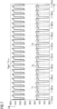
- Fig. 5 shows a diagram in which the time course of the voltages during a switch-off process of a switching device 1 with two switching modules connected in series is shown in higher temporal resolution.
- the voltage curve resulting across the controllable semiconductor switching element of the first switching module is designated U 1
- the voltage curve resulting across the controllable semiconductor switching element of the second switching module is designated U 2 .
- the resulting total voltage, which corresponds to the counter voltage U cv is shown as U tot .
- the time section shown between 10.443 ms and 10.479 ms clearly shows the clocking of the controllable semiconductor switching elements of the two switching modules.
- the clocked course of the voltage is also clearly visible in the total voltage U ges .
- Fig. 6 shows the time course of a countervoltage U cv generated by the switching device according to the invention together with the current I flowing in the current path.
- Fig. 7 shows the time course of the module voltages U 1 , U 2 and U 3 of three switching modules connected in series.
- the switching voltage can be further increased by increasing the number n of switching modules.
- Fig. 8 shows a variation of the in Fig. 1 switching module 10 shown.
- a further semiconductor switching element 16 is connected in anti-series to the controllable semiconductor switching element 13.
- the controllable semiconductor switching element 13 and the further controllable Semiconductor switching elements 16 can be of the same type, for example IGBTs.
- the behavior of this bidirectionally operable switching module 10 corresponds to the behavior of the switching module Fig. 1 .
- the current flow can be in Fig. 8 shown bidirectional switching module 10 can be directed in both directions.
- One of the two controllable semiconductor switching elements 13, 16 is switched on in the conductive case and the other is switched off.
- the current flow is ensured via a respective diode 17 or 18 connected in anti-parallel.
- Fig. 9 shows a further electrical equivalent circuit diagram of a switching device 1 according to the invention, which exemplarily comprises two switching devices 10-1 and 10-2. These are as in Fig. 3 connected between a source-side inductor 3 and a load-side inductor 5.
- the structure is described using the switching module 10-1, with the structure of the switching module 10-2 being identical.
- the rectifier bridge 20-1 is implemented as a diode bridge with four diodes 21-1, 22-1, 23-1 and 24-1.
- a first rectifier terminal 25-1 is formed between cathodes of the diodes 21-1 and 23-1.
- a second rectifier terminal 26-1 is formed between anode terminals of the diodes 22-1 and 24-1. That as in Fig. 1
- the switching module constructed is connected between the first rectifier connection 25-1 and the second rectifier connection 26-1.
- a third rectifier terminal 27-1 is formed between the anode of the diode 21-1 and the cathode of the diode 22-1.
- the third rectifier connection 27-1 is connected to the DC voltage source 2 via the source-side inductance 3.
- a fourth rectifier terminal 28-1 is formed between an anode of the diode 23-1 and a cathode of the diode 24-1.
- the fourth rectifier connection 28-1 is connected to the first rectifier connection 27-2 of the second switching module 10-2.
- a unidirectional basic module is thus arranged in the rectifier bridge 20-1, which together form the switching module 10-1. This is used for both current directions, with the current reversal being realized by the elements of the rectifier bridge 20-i.
- Fig. 9 only the DC voltage source 2 is shown to the left and the load 4 to the right of the switching device 1.
- the arrangement has a further DC voltage source to the right and a further load 4 to the left of the switching device 1.
- any number of the switching modules 10-i can be connected in series.
Description
Die Erfindung betrifft eine Schaltvorrichtung zum Auftrennen eines quell- und lastseitige Induktivitäten umfassenden Strompfads eines Gleichspannungsnetzes.The invention relates to a switching device for separating a current path of a DC voltage network comprising inductances on the source and load sides.
Eine Schaltvorrichtung, die zum Auftrennen eines quell- und lastseitige Induktivitäten umfassenden Strompfads eines Gleichspannungsnetzes vorgesehen ist, muss die Rückspeisung oder den Abbau von Energie aus dem Gleichspannungsnetz handhaben können.A switching device that is intended to separate a current path of a DC voltage network that includes source and load-side inductors must be able to handle the recovery or reduction of energy from the DC voltage network.
Werden, wie bei dem sog. ABB-Schalter, mechanische Schalter eingesetzt, so besteht die Gefahr der Entstehung eines Lichtbogens, sofern nicht sichergestellt werden kann, dass das Auftrennen des Strompfads im Nulldurchgang des Stroms erfolgt. Ein solches mechanisches Schaltelement muss daher durch eine aufwändige Beschaltung, z.B. durch das Vorsehen mehrerer Halbleiterschaltelemente und Varistoren als Überspannungsbegrenzer, geschützt werden. Dazu kann beispielsweise der im Hauptstromzweig liegende, schnell schaltende mechanische Schalter mit einem Halbleiterschaltelement, das im Durchlassfall einen geringen Spannungsabfall aufweist, verschaltet werden. Die Aufgabe dieses Halbleiterschaltelements beim Auftrennen des Lastpfads besteht darin, bei der Abschaltung einen Spannungsabfall zu erzeugen, damit der Strom in einen zu dieser Anordnung parallel geschalteten Hauptschalter geführt werden kann. Dieser Hauptschalter besteht aus einer Serienschaltung mehrerer Halbleiterschaltelemente, zu deren Überspannungsschutz jeweils ein Varistor parallel geschaltet ist. Fließt nun der Strom im Wesentlichen über den parallelen Pfad, so kann der schnelle mechanische Schalter ausgeschaltet werden, ohne dass ein Lichtbogen entsteht. Nachteil dieser Schaltvorrichtung ist die Komplexität aufgrund der Vielzahl an benötigten Halbleiterschaltelementen und Varistoren, wobei letztere sehr teuer und schwer sind.If mechanical switches are used, as is the case with the so-called ABB switch, there is a risk of an arc occurring unless it can be ensured that the current path is opened at zero crossing of the current. Such a mechanical switching element must therefore be protected by complex wiring, for example by providing several semiconductor switching elements and varistors as overvoltage limiters. For this purpose, for example, the fast-switching mechanical switch located in the main current branch can be connected to a semiconductor switching element that has a low voltage drop when on. The task of this semiconductor switching element when opening the load path is to generate a voltage drop when it is switched off so that the current can be fed into a main switch connected in parallel to this arrangement. This main switch consists of a series connection of several semiconductor switching elements, each of which has a varistor connected in parallel to protect against overvoltage. If the current now flows essentially via the parallel path, the fast mechanical switch can be switched off without an arc occurring. The disadvantage of this switching device is its complexity due to the large number of semiconductor switching elements and varistors required, the latter being very expensive and heavy.
Es sind auch Schaltvorrichtungen bekannt, die ausschließlich steuerbare Halbleiterschaltelemente, z.B. IGBTs umfassen. Bei dieser Variante können beispielsweise zwei Halbleiterschaltelemente anti-seriell in den Lastpfad geschaltet werden. Ohne weitere Maßnahmen kann diese Schaltvorrichtung jedoch nur in Gleichspannungsnetzen eingesetzt werden, welche keine große Induktivitäten aufweisen. Zudem werden spannungsbegrenzende Elemente, wie z.B. Varistoren und dergleichen, erforderlich, welche jedoch aus Kostengründen ungern verwendet werden.Switching devices are also known which exclusively include controllable semiconductor switching elements, for example IGBTs. In this variant, for example, two semiconductor switching elements can be connected in anti-serial fashion in the load path. However, without further measures, this switching device can only be used in DC voltage networks that do not have large inductances. In addition, voltage-limiting elements, such as varistors and the like, are required, but these are reluctant to be used for cost reasons.
Weiterhin sind sogenannte Hybridschalter bekannt, wie der sogenannte Marquardt-Schalter, welcher beim Abschalten einen künstlichen Stromdurchgang Null erzeugt, indem ein Gegenstrom aufgeprägt wird. Da im Normalbetrieb kein Halbleiterschaltelement im Strompfad liegt, können die Verluste dieses Hybridschalters sehr klein gehalten werden. Die Schaltgeschwindigkeit hängt von einem in dem Hybridschalter vorgesehenen mechanischen Schaltelement ab.Furthermore, so-called hybrid switches are known, such as the so-called Marquardt switch, which creates an artificial zero current crossing when switched off by imposing a countercurrent. Since there is no semiconductor switching element in the current path during normal operation, the losses of this hybrid switch can be kept very small. The switching speed depends on a mechanical switching element provided in the hybrid switch.
In der
Ein Problem der oben beschriebenen Schaltvorrichtungstypen ist die in den Netzinduktivitäten abzubauende Energie. Beim schnellen Abschalten bauen sich hohe Spannungen auf, die über eine Schutzbeschaltung abgebaut werden müssen, um Schäden an den Komponenten der Schaltvorrichtung zu verhindern. Keine der oben genannten Varianten löst dieses Problem in zufriedenstellender Weise hinsichtlich technischer Funktionalität und Wirtschaftlichkeit.A problem with the switching device types described above is the energy to be dissipated in the network inductors. When switching off quickly, high voltages build up, which must be reduced using a protective circuit in order to prevent damage to the components of the switching device. None of the above variants solves this problem satisfactorily in terms of technical functionality and cost-effectiveness.
Es ist Aufgabe der Erfindung, eine Schaltvorrichtung zum Auftrennen eines quell- und lastseitige Induktivitäten umfassenden Strompfads eines Gleichspannungsnetzes anzugeben, welche baulich und/oder funktionell verbessert ist. Insbesondere soll die Schaltvorrichtung mit geringeren Kosten bereitstellbarer sein.It is the object of the invention to provide a switching device for separating a current path of a DC voltage network comprising source and load inductors, which is structurally and/or functionally improved. In particular, the switching device should be able to be provided at lower costs.
Diese Aufgabe wird gelöst durch eine Schaltvorrichtung gemäß den Merkmalen des Patentanspruchs 1. Vorteilhafte Ausgestaltungen ergeben sich aus den abhängigen Ansprüchen.This task is solved by a switching device according to the features of
Es wird eine Schaltvorrichtung zum Auftrennen eines quell- und lastseitige Induktivitäten umfassenden Strompfads eines Gleichspannungsnetzes vorgeschlagen, die zumindest zwei in Serie verschaltete Schaltmodule umfasst. Jedes der Schaltmodule umfasst zumindest ein steuerbares Halbleiterschaltelement, dem eine Serienschaltung aus einem Widerstand und einem Kondensator parallel geschaltet ist, wobei die Schaltvorrichtung eingerichtet ist, die steuerbaren Halbleiterschaltelemente im Betrieb der Schaltvorrichtung zum Auftrennen des Strompfads bis zum Abbau der in den Induktivitäten gespeicherten Energie jeweils abwechselnd ein- und wieder auszuschalten, wobei Halbleiterschaltelemente unterschiedlicher Schaltmodule zu unterschiedlichen Zeitpunkten ein- und ausgeschaltet werden, sodass sich zu einem gegebenen Zeitpunkt zumindest ein Schaltmodul in einem sperrenden Zustand befindet.A switching device for separating a current path of a DC voltage network comprising source and load inductors is proposed, which comprises at least two switching modules connected in series. Each of the switching modules comprises at least one controllable semiconductor switching element, to which a series circuit consisting of a resistor and a capacitor is connected in parallel, the switching device being set up to alternately switch the controllable semiconductor switching elements during operation of the switching device to open the current path until the energy stored in the inductors is reduced on and off again, with semiconductor switching elements of different switching modules being switched on and off at different times, so that at least one switching module is in a blocking state at a given time.
Eine derartige Schaltvorrichtung ermöglicht einen "weichen" Abschaltvorgang, bei dem der Stromfluss in dem Strompfad nicht abrupt, sondern rampenförmig abgebaut wird. Durch wenigstens eines der zumindest zwei Schaltmodule wird eine Gegenspannung im Strompfad aufgebaut. Dies wird durch einen Betrieb des jeweiligen Halbleiterschalterelements der Schaltmodule im getakteten Bereich ermöglicht. Damit wird die hohe Verlustleistung im Abschaltfall nicht in dem Halbleiterschaltelement der jeweiligen Schaltmodule umgesetzt, sondern überwiegend in dem Widerstand der jeweiligen Schaltmodule. Die Schaltvorrichtung kann dadurch auf spannungsbegrenzende Bauelemente, wie Varistoren, verzichten, die teuer, schwer und bauraumintensiv sind. Das Halbleiterschaltelement in den jeweiligen Schaltmodulen übernimmt dabei die Rolle des Bremschoppers. Gleichzeitig kann der jeweilige Kondensator der Schaltmodule klein dimensioniert werden, da er nicht die gesamte, in den quell- und lastseitigen Induktivitäten gespeicherte Energie aufnehmen muss, sondern lediglich einen kleinen Teil aufgrund des getakteten Betriebs des Halbleiterschaltelements der betreffenden Schaltmodule. Die abzubauende Gesamtenergie ist damit nicht durch das Halbleiterschaltelement der betreffenden Schaltmodule begrenzt. Lediglich dauert der Abschaltvorgang bei größeren quell- und lastseitigen Induktivitäten länger.Such a switching device enables a “soft” switch-off process in which the current flow in the current path is not reduced abruptly, but rather in a ramp-like manner. A counter voltage is built up in the current path by at least one of the at least two switching modules. This is made possible by operating the respective semiconductor switch element of the switching modules in the clocked range. This means that the high power loss in the event of a switch-off does not occur in the semiconductor switching element of the respective switching modules, but predominantly in the resistance of the respective switching modules. The switching device can thereby dispense with voltage-limiting components, such as varistors, which are expensive, heavy and require a lot of installation space. The semiconductor switching element in the respective switching modules takes on the role of the brake chopper. At the same time, the respective capacitor of the switching modules can be dimensioned small, since it does not have to absorb all of the energy stored in the source and load side inductors, but only a small part due to the clocked operation of the semiconductor switching element of the switching modules in question. The total energy to be dissipated is therefore not limited by the semiconductor switching element of the switching modules in question. The switch-off process only takes longer with larger source and load inductances.
Ein Vorteilhafter Einsatz der Schaltvorrichtung ist insbesondere in Schiffen möglich, dort insbesondere in Mittelspannungs-DC-Netzen. Ein schneller und sicherer DC-Schalter ermöglicht dort eine sichere Trennung von DC-Zonen, beispielsweise bei Flutung oder anderen Abschaltszenarien. Generell gilt dies auch im Betrieb von anderen Inselnetzen, bei denen verschiedene Zonen sicher und schnell trennbar bleiben müssen.An advantageous use of the switching device is possible in particular in ships, particularly in medium-voltage DC networks. A fast and safe DC switch enables safe isolation of DC zones, for example in the event of flooding or other shutdown scenarios. In general, this also applies to the operation of other island networks, where different zones must remain safe and quickly separable.
Eine zweckmäßige Ausgestaltung gemäß einer ersten Variante sieht vor, dass die Parallelschaltung aus dem zumindest einen steuerbaren Schaltelement und der Serienschaltung aus dem Widerstand und dem Kondensator zwischen einem ersten Schaltmodulanschluss und einem zweiten Schaltmodulanschluss des jeweiligen Schaltmoduls verschaltet ist. Eine Mehrzahl an seriell verschalteten Schaltmodulen kann dann derart verschaltet werden, dass ein erster Schaltmodulanschluss eines Schaltmoduls mit dem zweiten Schaltmodulanschluss eines vorhergehenden Schaltmoduls verschaltet ist. Der erste Schaltmodulanschluss eines ersten Schaltmoduls ist über eine quellseitige Induktivität mit einer Gleichspannungsquelle, ein zweiter Schaltmodulanschluss eines letzten Schaltmoduls der Mehrzahl an Schaltmodulen über eine lastseitige Induktivität mit einer Last verschaltet. Ein derartiges Schaltmodul, bei dem zumindest ein steuerbares Halbleiterschaltelement, ein Widerstand und ein Kondensator vorgesehen sind, kommt mit einer minimalen Anzahl an Bauelementen aus.An expedient embodiment according to a first variant provides that the parallel circuit consisting of the at least one controllable switching element and the series circuit consisting of the resistor and the capacitor is connected between a first switching module connection and a second switching module connection of the respective switching module. A plurality of serially connected switching modules can then be connected in such a way that a first switching module connection of a switching module is connected to the second switching module connection of a preceding switching module. The first switching module connection of a first switching module is connected to a DC voltage source via a source-side inductor, a second one Switching module connection of a last switching module of the plurality of switching modules is connected to a load via a load-side inductance. Such a switching module, in which at least one controllable semiconductor switching element, a resistor and a capacitor are provided, requires a minimum number of components.
Eine weitere zweckmäßige Ausgestaltung gemäß einer zweiten Variante sieht vor, dass die Parallelschaltung aus genau einem steuerbaren Halbleiterschaltelement und der Serienschaltung aus dem Widerstand und dem Kondensator (sog. Grundmodul) zwischen einem ersten Gleichrichtanschluss und einem zweiten Gleichrichtanschluss einer Gleichrichterbrücke des jeweiligen Schaltmoduls verschaltet ist. Der erste Gleichrichtanschluss ist ein erster Knotenpunkt der Gleichrichterbrücke, an den Kathodenanschlüsse zweier Gleichrichtelemente miteinander verschaltet sind. Der zweite Gleichrichtanschluss ist ein zweiter Knotenpunkt der Gleichrichterbrücke, an dem Anodenanschlüsse zweier weiterer Gleichrichtelemente miteinander verschaltet sind. Wird ein unidirektionales Grundmodul, d.h. ein Schaltmodul, das lediglich ein einziges Halbleiterschaltelement umfasst, in der Gleichrichterbrücke vorgesehen, so kann das Schaltmodul für beide Stromrichtungen genutzt werden. Eine Stromumkehr wird durch die Gleichrichterbrücke, welche im einfachsten Fall eine Diodenbrücke ist, realisiert.A further expedient embodiment according to a second variant provides that the parallel connection of exactly one controllable semiconductor switching element and the series connection of the resistor and the capacitor (so-called basic module) is connected between a first rectification connection and a second rectification connection of a rectifier bridge of the respective switching module. The first rectification connection is a first node of the rectifier bridge, at which cathode connections of two rectification elements are interconnected. The second rectification connection is a second node of the rectifier bridge, at which anode connections of two further rectification elements are interconnected. If a unidirectional basic module, i.e. a switching module that only includes a single semiconductor switching element, is provided in the rectifier bridge, the switching module can be used for both current directions. A current reversal is achieved by the rectifier bridge, which in the simplest case is a diode bridge.
Gemäß dieser Ausgestaltung kann eine beliebige Anzahl an Schaltmodulen in Reihe verschaltet werden. Die Reihenschaltung erfolgt dabei derart, dass ein dritter Gleichrichtanschluss eines Schaltmoduls mit einem vierten Gleichrichtanschluss eines vorhergehenden Schaltmoduls verschaltet wird. Der dritte Gleichrichtanschluss ist ein dritter Knotenpunkt der Gleichrichterbrücke, an dem ein Kathodenanschluss eines Gleichrichtelements mit einem Anodenanschluss eines anderen Gleichrichtelements miteinander verschaltet ist. In entsprechender Weise ist der vierte Gleichrichtanschluss ein vierter Knotenpunkt der Gleichrichterbrücke, an dem ein Kathodenanschluss eines Gleichrichtelements mit einem Kathodenanschluss eines anderen Gleichrichtelements miteinander verschaltet ist.According to this embodiment, any number of switching modules can be connected in series. The series connection is carried out in such a way that a third rectification connection of a switching module is connected to a fourth rectification connection of a previous switching module. The third rectification connection is a third node of the rectifier bridge, at which a cathode connection of one rectification element is connected to an anode connection of another rectification element. In a corresponding manner, the fourth rectification connection is a fourth node of the rectifier bridge, at which a cathode connection of a rectification element is connected to a cathode connection another rectifying element is interconnected.
Eine weitere zweckmäßige Ausgestaltung sieht vor, dass im Betrieb der Schaltvorrichtung zum Auftrennen des Strompfads bis zum Abbau der in den quell- und lastseitigen Induktivitäten gespeicherten Energie zu einem gegebenen Zeitpunkt das steuerbare Halbleiterschaltelement zumindest eines Schaltmoduls sperrend geschaltet ist. Somit kann verhindert werden, dass z.B. bei einem Auftrennvorgang aufgrund eines lastseitigen Kurzschlusses sich der Kurzschlussstrom wieder über die Schaltvorrichtung aufbauen kann.A further expedient embodiment provides that during operation of the switching device to open the current path until the energy stored in the source and load side inductors is reduced at a given time, the controllable semiconductor switching element of at least one switching module is switched to blocking. This can prevent the short-circuit current from building up again via the switching device during a disconnection process due to a short circuit on the load side.
Eine weitere zweckmäßige Ausgestaltung sieht vor, dass im Betrieb der Schaltvorrichtung zum Auftrennen des Strompfads bis zum Abbau der in den Induktivitäten gespeicherten Energie zu einem gegebenen Zeitpunkt das steuerbare Halbleiterschaltelement einer ersten Teilanzahl von Schaltmodulen sperrend geschaltet und eine zweite Teilanzahl von Schaltmodulen leitend geschaltet sind. Wie viele der Gesamtzahl der Schaltmodule leitend und wie viele sperrend geschaltet sind, kann durch eine übergeordnete Steuervorrichtung koordiniert werden oder aufgrund der sich in den jeweiligen Schaltmodulen einstellenden Spannungshöhen festgelegt sein.A further expedient embodiment provides that during operation of the switching device to open the current path until the energy stored in the inductors is reduced at a given point in time, the controllable semiconductor switching element of a first partial number of switching modules is switched off and a second partial number of switching modules are switched on. How many of the total number of switching modules are switched on and how many are switched off can be coordinated by a higher-level control device or can be determined based on the voltage levels that arise in the respective switching modules.
Eine weitere zweckmäßige Ausgestaltung sieht vor, dass im Betrieb der Schaltvorrichtung zum Auftrennen des Strompfads bis zum Abbau der in den Induktivitäten gespeicherten Energie das steuerbare Halbleiterschaltelement des- oder derjenigen Schaltmodule leitend geschaltet wird, über dessen oder deren Kondensator die Spannung einen vorgegebenen oberen Schwellwert erreicht. Beim sperrend Schalten der Schaltvorrichtung ist zu einem gegebenen Zeitpunkt zumindest ein Schaltmodul sperrend geschaltet. Anders ausgedrückt, das steuerbare Halbleiterschaltelement des betreffenden Schaltmoduls ist sperrend geschaltet. Damit kann der Strom in diesem Schaltmodul nur noch über den parallelen Pfad des RC-Glieds weiterflie-ßen. Der Kondensator des RC-Glieds lädt sich dadurch auf, bis die Spannung den vorgegeben oberen Schwellwert erreicht. Anschließend wird das steuerbare Halbleiterschaltelement dieses Schaltmoduls wieder leitend geschaltet, so dass sich der Kondensator über den seriell verschalteten Widerstand entladen kann.A further expedient embodiment provides that during operation of the switching device to open the current path until the energy stored in the inductors is reduced, the controllable semiconductor switching element of the switching module or modules is switched on, via whose capacitor the voltage reaches a predetermined upper threshold value. When the switching device is switched to blocking, at least one switching module is switched to blocking at a given time. In other words, the controllable semiconductor switching element of the switching module in question is switched to a blocking state. This means that the current in this switching module can only continue to flow via the parallel path of the RC element. This causes the capacitor of the RC element to charge until the voltage reaches the specified upper threshold value. The controllable semiconductor switching element of this switching module is then switched on again so that the capacitor can discharge via the series-connected resistor.
Eine weitere zweckmäßige Ausgestaltung sieht vor, dass im Betrieb der Schaltvorrichtung zum Auftrennen des Strompfads bis zum Abbau der in den Induktivitäten gespeicherten Energie das steuerbare Halbleiterschaltelement des- oder derjenigen Schaltmodule sperrend geschaltet wird, über dessen oder deren Kondensator die Spannung einen vorgegeben unteren Schwellwert erreicht. Sobald der untere Schwellwert erreicht ist, wird das steuerbare Halbleiterschaltelement des betreffenden Schaltmoduls wieder leitend geschaltet. Erfolgt die Lasttrennung aufgrund eines Kurzschlusses, so wird durch dieses Vorgehen zwar kurzzeitig wieder auf diesen Kurzschluss geschaltet. Da dies aber nur für kurze Zeit erfolgt, wird der Strom im Mittel abgebaut, da die quell- und lastseitigen Induktivitäten einen zu schnellen Anstieg verhindern.A further expedient embodiment provides that during operation of the switching device to open the current path until the energy stored in the inductors is reduced, the controllable semiconductor switching element of the switching module or modules is switched off, via whose capacitor the voltage reaches a predetermined lower threshold value. As soon as the lower threshold value is reached, the controllable semiconductor switching element of the relevant switching module is switched on again. If the load is disconnected due to a short circuit, this procedure will briefly switch back to this short circuit. However, since this only occurs for a short time, the current is reduced on average because the inductances on the source and load sides prevent it from increasing too quickly.
Eine weitere zweckmäßige Ausgestaltung sieht vor, dass im Betrieb der Schaltvorrichtung zum Auftrennen des Strompfads bis zum Abbau der in den Induktivitäten gespeicherten Energie das steuerbare Halbleiterschaltelement des- oder derjenigen Schaltmodule dauerhaft sperrend geschaltet wird, wenn über dessen oder deren Kondensator die Spannung den vorgegeben oberen Schwellwert nicht mehr erreicht. Die Spannung kann dadurch mit eigener Resonanz ausschwingen.A further expedient embodiment provides that during operation of the switching device to open the current path until the energy stored in the inductors is reduced, the controllable semiconductor switching element of the switching module or modules is permanently switched off when the voltage across its capacitor reaches the predetermined upper threshold value no longer achieved. This allows the tension to oscillate with its own resonance.
Eine weitere Ausgestaltung sieht vor, dass im Betrieb der Schaltvorrichtung zum Auftrennen des Strompfads bis zum Abbau der in den Induktivitäten gespeicherten Energie zu einem gegebenen Zeitpunkt das steuerbare Halbleiterschaltelement des Schaltmoduls leitend geschaltet wird, über deren Kondensator die höchste Spannung im Vergleich zu den Spannungen der Kondensatoren der übrigen Schaltmodule anliegt. Gemäß dieser Ausgestaltung wird zum Ausschalten eines steuerbaren Halbleiterschaltelements kein oberer Schwellwert ermittelt. Vielmehr werden die Spannungen über den Kondensatoren aller Schaltmodule separat ermittelt und miteinander verglichen. Das steuerbare Halbleiterschaltelement desjenigen Schaltmoduls, über dessen Kondensator die höchste Spannung abfällt, wird dann leitend geschaltet. Hierdurch ist sichergestellt, dass keine Überlastung des steuerbaren Halbleiterschaltelements eines jeweiligen Schaltmoduls, auch bei hohen Überspannungen auftreten kann. Hierdurch ergibt sich auch eine gewisse Zufälligkeit, in welchem Schaltzustand sich welches Schaltmodul zu einem gegebenen Schaltzeitpunkt befindet.A further embodiment provides that during operation of the switching device to open the current path until the energy stored in the inductors is reduced at a given time, the controllable semiconductor switching element of the switching module is switched on, across its capacitor the highest voltage compared to the voltages of the capacitors of the remaining switching modules. According to this embodiment, a controllable semiconductor switching element is switched off no upper threshold value determined. Rather, the voltages across the capacitors of all switching modules are determined separately and compared with each other. The controllable semiconductor switching element of the switching module whose capacitor has the highest voltage drop is then switched on. This ensures that no overloading of the controllable semiconductor switching element of a respective switching module can occur, even with high overvoltages. This also results in a certain randomness as to which switching state which switching module is in at a given switching time.
Eine weitere zweckmäßige Ausgestaltung sieht vor, dass in dem Pfad des steuerbaren Halbleiterschaltelements eines jeweiligen Schaltmoduls ein weiteres steuerbares Halbleiterschaltelement anti-seriell zu dem steuerbaren Halbleiterschaltelement verschaltet ist. Dadurch wird ein bidirektional betreibbares Schaltmodul bereitgestellt, so dass im Ergebnis die Schaltvorrichtung den Strompfad, unabhängig von der vorherrschenden Stromrichtung, abschalten kann.A further expedient embodiment provides that a further controllable semiconductor switching element is connected in anti-series to the controllable semiconductor switching element in the path of the controllable semiconductor switching element of a respective switching module. This provides a bidirectionally operable switching module, so that as a result the switching device can switch off the current path, regardless of the prevailing current direction.
Eine weitere zweckmäßige Ausgestaltung sieht vor, dass das steuerbare Halbleiterschaltelement ein abschaltbares Halbleiterschaltelement ist. Insbesondere können als steuerbare Halbleiterschaltelemente ein IGBT, ein MOSFET, ein IGCT oder ein Thyristor mit einer Abschalteinrichtung (sog. Löschkreis) eingesetzt werden.A further expedient embodiment provides that the controllable semiconductor switching element is a semiconductor switching element that can be switched off. In particular, an IGBT, a MOSFET, an IGCT or a thyristor with a switch-off device (so-called quenching circuit) can be used as controllable semiconductor switching elements.
Die beschriebene Schaltvorrichtung ist insbesondere für die Verwendung in einem Gleichspannungsnetz mit einer Spannung von mehr als 1000 V vorgesehen. Insbesondere lässt sich die Schaltvorrichtung in Hochspannungsgleichstromübertragungsleitungen einsetzen. In Abhängigkeit der in dem Gleichspannungsnetz vorherrschenden Spannung muss dann eine geeignete entsprechende Anzahl an Schaltmodulen der Schaltvorrichtung gewählt werden. Je höher die zu beherrschende Spannung in dem Gleichspannungsnetz ist, desto größer wird - gleiche Halbleiterschaltelemente vorausgesetzt - die Anzahl der Schaltmodule gewählt. Bei Gleichspannungsnetzen im Mittelspannungsbereich können insbesondere IGBTs oder MOSFETs zum Einsatz kommen. Bei noch höheren Spannungen kommen insbesondere Thyristoren mit einer Abschalteinrichtung oder IGCTs zum Einsatz. Eine weitere Ausgestaltung sieht vor, dass die Schaltvorrichtung der hier beschriebenen Art als Kurzschlussfester Leistungsschalter verwendet wird.The switching device described is intended in particular for use in a direct voltage network with a voltage of more than 1000 V. In particular, the switching device can be used in high-voltage direct current transmission lines. Depending on the voltage prevailing in the DC voltage network, a suitable corresponding number of switching modules of the switching device must then be selected. The higher the voltage to be controlled in the DC voltage network, the greater - assuming the same semiconductor switching elements - the number of switching modules chosen. In medium-voltage DC networks, IGBTs or MOSFETs in particular can be used. At even higher voltages, thyristors with a shutdown device or IGCTs are used. A further embodiment provides that the switching device of the type described here is used as a short-circuit-proof circuit breaker.
Die Erfindung wird nachfolgend näher anhand von Ausführungsbeispielen in der Zeichnung erläutert. Es zeigen:
- Fig. 1
- ein elektrisches Ersatzschaltbild, das den Aufbau eines einzelnen unidirektionalen Schaltmoduls für eine erfindungsgemäße Schaltvorrichtung zeigt;
- Fig. 2
- ein elektrisches Ersatzschaltbild einer seriellen Verschaltung von drei in
Fig. 1 gezeigten Schaltmodulen; - Fig. 3
- ein elektrisches Ersatzschaltbild einer erfindungsgemäßen Schaltvorrichtung in einem Gleichspannungsnetz mit quell- und lastseitigen Induktivitäten;
- Fig. 4
- ein Diagramm, das den zeitlichen Verlauf von Spannung und Strom bei einem Auftrennvorgang der erfindungsgemäßen Schaltvorrichtung mit zwei Schaltmodulen zeigt;
- Fig. 5
- ein Diagramm, das den zeitlichen Verlauf der über zwei seriell miteinander verschalteten Schaltmodulen anfallenden Spannung sowie der über der Schaltvorrichtung abfallenden Gesamtspannung zeigt;
- Fig. 6
- ein Diagramm, das den zeitlichen Verlauf von Spannung und Strom aufgrund der durch die erfindungsgemäße Schaltvorrichtung erzeugten Gegenspannung illustriert;
- Fig. 7
- ein Diagramm, das den zeitlichen Verlauf der Spannungen von drei seriell miteinander verschalteten Schaltmodulen sowie die sich daraus ergebende Gesamtspannung der Schaltvorrichtung zeigt;
- Fig. 8
- ein Ausführungsbeispiel eines erfindungsgemäßen bidirektionalen Schaltmoduls; und
- Fig. 9
- ein elektrisches Ersatzschaltbild einer erfindungsgemäßen Schaltvorrichtung in einem Gleichspannungsnetz, bei dem die Schaltvorrichtung aus zwei abgewandelten Schaltmodulen mit einem Brückengleichrichter besteht.
- Fig. 1
- an electrical equivalent circuit diagram showing the structure of a single unidirectional switching module for a switching device according to the invention;
- Fig. 2
- an electrical equivalent circuit diagram of a serial connection of three in
Fig. 1 switching modules shown; - Fig. 3
- an electrical equivalent circuit diagram of a switching device according to the invention in a DC voltage network with inductances on the source and load sides;
- Fig. 4
- a diagram showing the time course of voltage and current during a disconnection process of the switching device according to the invention with two switching modules;
- Fig. 5
- a diagram showing the time course of the voltage occurring across two switching modules connected in series and the total voltage dropping across the switching device;
- Fig. 6
- a diagram illustrating the time course of voltage and current due to the counter voltage generated by the switching device according to the invention;
- Fig. 7
- a diagram showing the time course of the voltages of three switching modules connected in series and the resulting total voltage of the switching device;
- Fig. 8
- an embodiment of a bidirectional switching module according to the invention; and
- Fig. 9
- an electrical equivalent circuit diagram of a switching device according to the invention in a DC voltage network, in which the switching device consists of two modified switching modules with a bridge rectifier.
In der nachfolgenden Beschreibung sind gleiche Elemente mit gleichen Bezugszeichen versehen.In the following description, the same elements are given the same reference numerals.
Die prinzipielle Funktionsweise eines solchen einzelnen Schaltmoduls der erfindungsgemäßen Schaltvorrichtung 1 ist wie folgt: Soll die Schaltvorrichtung 1 Strom führen, so ist das steuerbare Halbleiterschaltelement 13 leitend geschaltet.The basic operation of such an individual switching module of the
Sobald der Strompfad 6 mit Hilfe der Schaltvorrichtung 1 aufgetrennt werden soll, wird das steuerbare Halbleiterschaltelement 13 durch eine in den Figuren nicht gezeigte Steuervorrichtung sperrend geschaltet. Dadurch kann der in dem Strompfad 6 fließende Strom I nur noch über das aus dem Widerstand 14 und dem Kondensator 15 gebildete RC-Glied weiter fließen. Der Kondensator 15 lädt sich infolge des in ihn fließenden Stroms I auf, bis ein vorgegebener oberer Schwellwert der über ihm abfallenden Spannung erreicht ist. Hierzu kann eine entsprechende Messvorrichtung (nicht dargestellt) in dem Schaltmodul 10 vorgesehen sein. Sobald der vorgegebene obere Schwellwert erreicht ist, wird das steuerbare Halbleiterschaltelement 13 wieder leitend geschaltet. Dadurch kann sich der Kondensator 15 über den Widerstand 14 entladen. Sobald ein vorgegebener unterer Schwellwert der über dem Kondensator 15 abfallenden Spannung erreicht ist, wird das steuerbare Halbleiterschaltelement 13 mittels seiner Steuervorrichtung wieder leitend geschaltet.As soon as the
Erfolgt die Auftrennung des Strompfades 6 beispielsweise aufgrund eines in dem Gleichspannungsnetz auftretenden Kurzschlusses, so wird durch das Wiedereinschalten (leitend Schalten des steuerbaren Halbleiterschaltelements 13) es dem Kurzschlussstrom ermöglicht wieder durch das Schaltmodul 10 zu fließen. Da die Einschaltdauer des steuerbaren Halbleiterschaltelements 13 jedoch sehr kurz ist, wird der in dem Strompfad 6 fließende Strom I im Mittel abgebaut, weil die in
Würde die Schaltvorrichtung 1 lediglich ein einziges Schaltmodul 1, wie in
Um mit Hilfe der vorgeschlagenen Schaltvorrichtung 1 zum Auftrennen eines Strompfands eines Gleichspannungsnetzes mit höheren Spannungen realisieren zu können, ist daher gemäß
Die Funktionsweise der in
Anders als bei der Verwendung eines einzigen Schaltmoduls liegt bei einer Mehrzahl von Schaltmodulen immer eine Gegenspannung (d.h. eine entgegen der Spannungsrichtung der Gleichspannungsquelle 2 gerichtete Spannung) im Gleichspannungsnetz an. Wenn die Anzahl n der in Serie verschalteten Schaltmodule sehr groß ist, fällt das kurzzeitige Kurzschlie-ßen eines Schaltmoduls kaum ins Gewicht, wodurch sich der Strom allmählich abbaut.In contrast to the use of a single switching module, with a plurality of switching modules there is always a counter voltage (i.e. a voltage directed opposite to the voltage direction of the DC voltage source 2) in the DC voltage network. If the number n of switching modules connected in series is very large, the short-circuiting of a switching module is of little importance, as a result of which the current is gradually reduced.
Sobald die vorgegebene obere Schaltschwelle in allen steuerbaren Halbleiterschaltelementen 13-i nicht mehr erreicht wird, bleiben alle steuerbaren Halbleiterschaltelemente 13-i der Schaltmodule 10-i dauerhaft gesperrt. Die Spannung im Gleichspannungsnetz schwingt dann mit Eigenresonanz aus.As soon as the specified upper switching threshold is no longer reached in all controllable semiconductor switching elements 13-i, all controllable semiconductor switching elements 13-i of the switching modules 10-i remain permanently blocked. The voltage in the DC voltage network then oscillates with natural resonance.
Das beschriebene Vorgehen, wird unabhängig davon, wie groß die Anzahl n der in Reihe verschalteten Schaltmodule ist, in entsprechender Weise durchgeführt. Welche der steuerbaren Halbleiterschaltelemente 13-i zu einem gegebenen Zeitpunkt sperrend und welche anderen steuerbaren Halbleiterschaltelement 13-i leitend geschaltet sind, kann entweder unter gezielter Steuerung der erwähnten, jedoch nicht gezeigten Steuereinheit erfolgen. Ebenso kann durch die geeignete, unterschiedliche Wahl jeweiliger oberer Schaltschwellen das zeitliche Verhalten des Ein- und Ausschaltens des zugeordneten steuerbaren Halbleiterschaltelements beeinflusst werden.The procedure described is carried out in a corresponding manner, regardless of how large the number n of switching modules connected in series is. Which of the controllable semiconductor switching elements 13-i are turned off at a given time and which other controllable semiconductor switching elements 13-i are turned on can either be done under targeted control of the control unit mentioned, but not shown. Likewise, the temporal behavior of switching the associated controllable semiconductor switching element on and off can be influenced by the appropriate, different selection of respective upper switching thresholds.
In einer anderen Alternative kann die über den jeweiligen Kondensatoren 15-i anliegende Spannung durch entsprechende Messmittel (nicht gezeigt) überwacht werden. Dabei wird das dem Kondensator, bei dem die höchste Spannung anliegt, zugeordnete steuerbare Halbleiterschaltelement leitend geschaltet, bis der vorgegebene untere Schwellwert erreicht ist. Da zu unterschiedlichen Zeitpunkten immer unterschiedliche Schaltmodule bzw. deren Kondensatoren eine höchste Spannung aufweisen, ergibt sich ein mehr oder minder zufälliges Ein- und Ausschalten der steuerbaren Halbleiterschaltelemente 13-i der Schaltmodule 10-i.In another alternative, the voltage across the respective capacitors 15-i can be monitored by appropriate measuring means (not shown). The controllable semiconductor switching element assigned to the capacitor to which the highest voltage is applied is switched on until the predetermined lower threshold value is reached. Since different switching modules or their capacitors always have the highest voltage at different times, this results in a more or less random occurrence. and switching off the controllable semiconductor switching elements 13-i of the switching modules 10-i.
Allgemein kann durch die Erhöhung der Anzahl n der Schaltmodule die Schaltspannung weiter erhöht werden.In general, the switching voltage can be further increased by increasing the number n of switching modules.
Die Gleichrichterbrücke 20-1 ist als Diodenbrücke mit vier Dioden 21-1, 22-1, 23-1 und 24-1 realisiert. Ein erster Gleichrichteranschluss 25-1 ist zwischen Kathoden der Dioden 21-1 und 23-1 gebildet. Ein zweiter Gleichrichteranschluss 26-1 ist zwischen Anodenanschlüssen der Dioden 22-1 und 24-1 gebildet. Das wie in
Der vierte Gleichrichteranschluss 28-1 ist mit dem ersten Gleichrichteranschluss 27-2 des zweiten Schaltmoduls 10-2 verschaltet.The fourth rectifier connection 28-1 is connected to the first rectifier connection 27-2 of the second switching module 10-2.
In der Gleichrichterbrücke 20-1 ist somit ein unidirektionales Grundmodul angeordnet, welche zusammen das Schaltmodul 10-1 ergeben. Dieses wird für beide Stromrichtungen genutzt, wobei die Stromumkehr durch die Elemente der Gleichrichterbrücke 20-i realisiert wird. Der Einfachheit halber sind
Wie in
Claims (13)
- Switching device (1) for disconnecting a current path (6) in a DC supply system, said current path (6) comprising inductances (3, 5) at the source end and the load end, which comprises at least two series-connected switching modules (10), wherein each of the switching modules (10) comprises at least one controllable semiconductor switching element (13, 16), to which a series circuit consisting of a resistor (14) and a capacitor (15) is connected in parallel, characterized in that, in the operation of the switching device for disconnecting the current path (6), pending the clearance of the energy stored in the inductances (3, 5), the switching device is configured to respectively switch the controllable semiconductor switching elements on and off again in an alternating manner, wherein semiconductor switching elements of different switching modules (10) are switched on and off at different time points, with the result that at least one switching module is in a blocking state at any given time point.
- Switching device according to Claim 1,
characterized in that the parallel-connected arrangement of the at least one controllable semiconductor switching element (13, 16) and the series-connected arrangement of the resistor (14) and the capacitor (15) is interconnected between a first switching module terminal (11) and a second switching module terminal (12) of the respective switching module (10). - Switching device according to Claim 1,
characterized in that the parallel-connected arrangement of the at least one controllable semiconductor switching element (13, 16) and the series-connected arrangement of the resistor (14) and the capacitor (15) is interconnected between a first rectifier terminal (25) and a second rectifier terminal (26) of a rectifier bridge (20) of the respective switching module (10), wherein the first rectifier terminal (25) is a first node point of the rectifier bridge (20), on which cathode terminals of two rectifier components (21, 23) are mutually interconnected, and wherein the second rectifier terminal (26) is a second node point (26) of the rectifier bridge (20), on which anode terminals of two further rectifier components (22, 24) are mutually interconnected. - Switching device according to one of the preceding claims, characterized in that, in the operation of the switching device (1) for disconnecting the current path (6), pending the clearance of the energy stored in the inductances (3, 5), at a given time point, the controllable semiconductor switching element (13, 16) of at least one switching module (10) is switched to a blocking state.
- Switching device according to one of the preceding claims, characterized in that, in the operation of the switching device for disconnecting the current path (6), pending the clearance of the energy stored in the inductances (3, 5), at a given time point, the controllable semiconductor switching element (13, 16) of a first partial number of switching modules (10) is switched to a blocking state, and a second partial number of switching modules (10) is switched to a conducting state.
- Switching device according to one of the preceding claims, characterized in that, in the operation of the switching device for disconnecting the current path (6), pending the clearance of the energy stored in the inductances (3, 5), the controllable semiconductor switching element (13, 16) of that or those switching module(s) (10) is switched to a conducting state, across the capacitor(s) (15) of which the voltage achieves a predefined upper threshold value.
- Switching device according to one of the preceding claims, characterized in that, in the operation of the switching device for disconnecting the current path (6), pending the clearance of the energy stored in the inductances (3, 5), the controllable semiconductor switching element (13, 16) of that or those switching module(s) (10) is switched to a blocking state, across the capacitor(s) (15) of which the voltage achieves a predefined lower threshold value.
- Switching device according to one of the preceding claims, characterized in that, in the operation of the switching device for disconnecting the current path (6), pending the clearance of the energy stored in the inductances (3, 5), the controllable semiconductor switching element (13, 16) of that or those switching module(s) (10) is permanently switched to a blocking state, if, via the capacitor(s) (15) thereof, the voltage no longer achieves the predefined threshold value.
- Switching device according to one of the preceding claims, characterized in that, in the operation of the switching device for disconnecting the current path (6), pending the clearance of the energy stored in the inductances (3, 5), at a given time point, the controllable semiconductor switching element (13, 16) of the switching module (10) is switched to a conducting state, on the capacitor (15) of which the highest voltage is present, in comparison with the voltages on the capacitors (15) of the remaining switching modules (10).
- Switching device according to one of the preceding claims, characterized in that, in the path of the controllable semiconductor switching element of a respective switching module (10), a further controllable semiconductor switching element (13, 16) is interconnected in an anti-series arrangement with the controllable semiconductor switching element (13, 16) .
- Switching device according to one of the preceding claims, characterized in that the controllable semiconductor switching element (13, 16) is an interruptible semiconductor switching element (13, 16), specifically an IGBT, a MOSFET, an IGCT or a thyristor having a cut-off device.
- Switching device according to one of the preceding claims, characterized in that the latter is provided for use in a DC supply system having a voltage greater than 1,000 V.
- Application of the switching device according to one of the preceding claims as a short-circuit-proof power switch.
Applications Claiming Priority (2)
| Application Number | Priority Date | Filing Date | Title |
|---|---|---|---|
| EP17158392.5A EP3367567A1 (en) | 2017-02-28 | 2017-02-28 | Switching device for separating a current path |
| PCT/EP2018/054775 WO2018158233A1 (en) | 2017-02-28 | 2018-02-27 | Switching device for disconnecting a current path |
Publications (4)
| Publication Number | Publication Date |
|---|---|
| EP3571766A1 EP3571766A1 (en) | 2019-11-27 |
| EP3571766B1 true EP3571766B1 (en) | 2023-10-11 |
| EP3571766C0 EP3571766C0 (en) | 2023-10-11 |
| EP3571766B8 EP3571766B8 (en) | 2023-11-15 |
Family
ID=58264377
Family Applications (2)
| Application Number | Title | Priority Date | Filing Date |
|---|---|---|---|
| EP17158392.5A Withdrawn EP3367567A1 (en) | 2017-02-28 | 2017-02-28 | Switching device for separating a current path |
| EP18710365.0A Active EP3571766B8 (en) | 2017-02-28 | 2018-02-27 | Switching device for separating a current path |
Family Applications Before (1)
| Application Number | Title | Priority Date | Filing Date |
|---|---|---|---|
| EP17158392.5A Withdrawn EP3367567A1 (en) | 2017-02-28 | 2017-02-28 | Switching device for separating a current path |
Country Status (6)
| Country | Link |
|---|---|
| US (1) | US11258437B2 (en) |
| EP (2) | EP3367567A1 (en) |
| KR (1) | KR102227376B1 (en) |
| CN (1) | CN110352558B (en) |
| AU (1) | AU2018227938B2 (en) |
| WO (1) | WO2018158233A1 (en) |
Families Citing this family (7)
| Publication number | Priority date | Publication date | Assignee | Title |
|---|---|---|---|---|
| DE102018215827B3 (en) * | 2018-09-18 | 2019-09-19 | Siemens Aktiengesellschaft | Switching device for separating a current path |
| DE102018215881B3 (en) * | 2018-09-19 | 2020-02-06 | Siemens Aktiengesellschaft | Device and method for coupling two direct current networks |
| EP3654477A1 (en) * | 2018-11-15 | 2020-05-20 | Siemens Aktiengesellschaft | Electronic switch with surge protector |
| EP3694105A1 (en) | 2019-02-05 | 2020-08-12 | Siemens Aktiengesellschaft | Switching device for separating a current path |
| DE102019107112B3 (en) * | 2019-03-20 | 2020-07-09 | Lisa Dräxlmaier GmbH | Switching device, voltage supply system, method for operating a switching device and manufacturing method |
| DE102019203983B4 (en) * | 2019-03-22 | 2020-10-08 | Siemens Aktiengesellschaft | DC voltage switch |
| EP3859778A1 (en) | 2020-02-03 | 2021-08-04 | Siemens Aktiengesellschaft | Quick electronic switch |
Citations (2)
| Publication number | Priority date | Publication date | Assignee | Title |
|---|---|---|---|---|
| DE10350361A1 (en) * | 2003-10-29 | 2005-06-02 | Siemens Ag | Method for limiting potential at collector of switchable power semiconductor switch, e.g. insulated gate bipolar transistor (IGBET), MOSFET, hard driven gat turn (HDGTO) of thyristor etc., to preset value |
| EP3032733A1 (en) * | 2014-12-13 | 2016-06-15 | Baumüller Nürnberg GmbH | Method for operating a 3-level inverter and inverter |
Family Cites Families (5)
| Publication number | Priority date | Publication date | Assignee | Title |
|---|---|---|---|---|
| JP2928159B2 (en) | 1996-04-12 | 1999-08-03 | 日本原子力研究所 | High-speed semiconductor switch circuit |
| EP2264894B1 (en) | 2009-06-19 | 2011-10-12 | Vincotech Holdings S.a.r.l. | Power module with additional transient current path and power module system |
| NZ601067A (en) * | 2010-02-03 | 2014-03-28 | Abb Technology Ag | Switching module to limit and/or break the current of an electric power line |
| EP2810289B1 (en) * | 2012-03-09 | 2016-05-04 | Siemens Aktiengesellschaft | Method for connecting a direct current network section by means of dc current switch |
| WO2014086432A1 (en) * | 2012-12-07 | 2014-06-12 | Siemens Aktiengesellschaft | Dc voltage power switch |
-
2017
- 2017-02-28 EP EP17158392.5A patent/EP3367567A1/en not_active Withdrawn
-
2018
- 2018-02-27 US US16/488,750 patent/US11258437B2/en active Active
- 2018-02-27 AU AU2018227938A patent/AU2018227938B2/en active Active
- 2018-02-27 KR KR1020197028369A patent/KR102227376B1/en active IP Right Grant
- 2018-02-27 WO PCT/EP2018/054775 patent/WO2018158233A1/en active Search and Examination
- 2018-02-27 CN CN201880014311.XA patent/CN110352558B/en active Active
- 2018-02-27 EP EP18710365.0A patent/EP3571766B8/en active Active
Patent Citations (2)
| Publication number | Priority date | Publication date | Assignee | Title |
|---|---|---|---|---|
| DE10350361A1 (en) * | 2003-10-29 | 2005-06-02 | Siemens Ag | Method for limiting potential at collector of switchable power semiconductor switch, e.g. insulated gate bipolar transistor (IGBET), MOSFET, hard driven gat turn (HDGTO) of thyristor etc., to preset value |
| EP3032733A1 (en) * | 2014-12-13 | 2016-06-15 | Baumüller Nürnberg GmbH | Method for operating a 3-level inverter and inverter |
Also Published As
| Publication number | Publication date |
|---|---|
| AU2018227938A1 (en) | 2019-08-22 |
| CN110352558A (en) | 2019-10-18 |
| AU2018227938B2 (en) | 2020-10-15 |
| EP3571766C0 (en) | 2023-10-11 |
| KR20190121829A (en) | 2019-10-28 |
| US20210135664A1 (en) | 2021-05-06 |
| EP3571766B8 (en) | 2023-11-15 |
| EP3367567A1 (en) | 2018-08-29 |
| KR102227376B1 (en) | 2021-03-11 |
| EP3571766A1 (en) | 2019-11-27 |
| CN110352558B (en) | 2023-07-28 |
| US11258437B2 (en) | 2022-02-22 |
| WO2018158233A1 (en) | 2018-09-07 |
Similar Documents
| Publication | Publication Date | Title |
|---|---|---|
| EP3571766B1 (en) | Switching device for separating a current path | |
| EP2810290B1 (en) | Apparatus for switching of direct current in a dc network terminal | |
| DE102015109466A1 (en) | Power converter submodule with short-circuit device and converter with this | |
| WO2007022744A1 (en) | Current-limiting switch | |
| EP3794730B1 (en) | Switching device for separating a current path | |
| EP2537219A1 (en) | Surge-limiting device for direct current networks | |
| EP2810291B1 (en) | Apparatus for switching dc current | |
| WO2001073932A1 (en) | Method for protecting a matrix converter against overvoltages and an active overvoltage device | |
| EP3403271B1 (en) | Device for switching a dc current in a pole of a dc voltage network | |
| EP3853957B1 (en) | Electronic switch with overvoltage protection | |
| EP2845214B1 (en) | Apparatus for switching in a dc voltage mains | |
| EP3694105A1 (en) | Switching device for separating a current path | |
| EP3935706B1 (en) | Dc network | |
| DE102018215881B3 (en) | Device and method for coupling two direct current networks | |
| EP3571750B1 (en) | Apparatus for limiting voltage for a dc voltage network | |
| DE102004016456A1 (en) | Electric power generator has electric power switch connected to parallel circuits of stator, for connecting each phase of generator to electric power network | |
| DE102020206250B3 (en) | Overvoltage protection | |
| DE102020206253B3 (en) | Overvoltage protection | |
| EP3043473B1 (en) | Circuit assembly for thyristor controller | |
| WO2020188055A1 (en) | Switching apparatus, voltage supply system, method for operating a switching apparatus, and production method | |
| WO2007093229A1 (en) | Protective circuit for disconnectable power semiconductors | |
| WO2009121724A1 (en) | Switchable freewheeling circuit for matrix converters | |
| DE102017106770A1 (en) | Circuit arrangement for protection against mains overvoltages for power converters of vehicles, in particular of overhead line vehicles |
Legal Events
| Date | Code | Title | Description |
|---|---|---|---|
| STAA | Information on the status of an ep patent application or granted ep patent |
Free format text: STATUS: UNKNOWN |
|
| STAA | Information on the status of an ep patent application or granted ep patent |
Free format text: STATUS: THE INTERNATIONAL PUBLICATION HAS BEEN MADE |
|
| PUAI | Public reference made under article 153(3) epc to a published international application that has entered the european phase |
Free format text: ORIGINAL CODE: 0009012 |
|
| STAA | Information on the status of an ep patent application or granted ep patent |
Free format text: STATUS: REQUEST FOR EXAMINATION WAS MADE |
|
| 17P | Request for examination filed |
Effective date: 20190820 |
|
| AK | Designated contracting states |
Kind code of ref document: A1 Designated state(s): AL AT BE BG CH CY CZ DE DK EE ES FI FR GB GR HR HU IE IS IT LI LT LU LV MC MK MT NL NO PL PT RO RS SE SI SK SM TR |
|
| AX | Request for extension of the european patent |
Extension state: BA ME |
|
| DAV | Request for validation of the european patent (deleted) | ||
| DAX | Request for extension of the european patent (deleted) | ||
| RAP1 | Party data changed (applicant data changed or rights of an application transferred) |
Owner name: SIEMENS ENERGY GLOBAL GMBH & CO. KG |
|
| STAA | Information on the status of an ep patent application or granted ep patent |
Free format text: STATUS: EXAMINATION IS IN PROGRESS |
|
| STAA | Information on the status of an ep patent application or granted ep patent |
Free format text: STATUS: EXAMINATION IS IN PROGRESS |
|
| 17Q | First examination report despatched |
Effective date: 20211109 |
|
| GRAP | Despatch of communication of intention to grant a patent |
Free format text: ORIGINAL CODE: EPIDOSNIGR1 |
|
| STAA | Information on the status of an ep patent application or granted ep patent |
Free format text: STATUS: GRANT OF PATENT IS INTENDED |
|
| INTG | Intention to grant announced |
Effective date: 20230512 |
|
| GRAS | Grant fee paid |
Free format text: ORIGINAL CODE: EPIDOSNIGR3 |
|
| GRAA | (expected) grant |
Free format text: ORIGINAL CODE: 0009210 |
|
| STAA | Information on the status of an ep patent application or granted ep patent |
Free format text: STATUS: THE PATENT HAS BEEN GRANTED |
|
| AK | Designated contracting states |
Kind code of ref document: B1 Designated state(s): AL AT BE BG CH CY CZ DE DK EE ES FI FR GB GR HR HU IE IS IT LI LT LU LV MC MK MT NL NO PL PT RO RS SE SI SK SM TR |
|
| REG | Reference to a national code |
Ref country code: GB Ref legal event code: FG4D Free format text: NOT ENGLISH |
|
| REG | Reference to a national code |
Ref country code: CH Ref legal event code: EP |
|
| REG | Reference to a national code |
Ref country code: DE Ref legal event code: R096 Ref document number: 502018013430 Country of ref document: DE |
|
| REG | Reference to a national code |
Ref country code: CH Ref legal event code: PK Free format text: BERICHTIGUNG B8 |
|
| REG | Reference to a national code |
Ref country code: IE Ref legal event code: FG4D Free format text: LANGUAGE OF EP DOCUMENT: GERMAN |
|
| RAP4 | Party data changed (patent owner data changed or rights of a patent transferred) |
Owner name: SIEMENS AKTIENGESELLSCHAFT Owner name: SIEMENS ENERGY GLOBAL GMBH & CO. KG |
|
| U01 | Request for unitary effect filed |
Effective date: 20231027 |
|
| U07 | Unitary effect registered |
Designated state(s): AT BE BG DE DK EE FI FR IT LT LU LV MT NL PT SE SI Effective date: 20231103 |
|
| REG | Reference to a national code |
Ref country code: NO Ref legal event code: T2 Effective date: 20231011 |
|
| U20 | Renewal fee paid [unitary effect] |
Year of fee payment: 7 Effective date: 20240226 |
|
| PG25 | Lapsed in a contracting state [announced via postgrant information from national office to epo] |
Ref country code: GR Free format text: LAPSE BECAUSE OF FAILURE TO SUBMIT A TRANSLATION OF THE DESCRIPTION OR TO PAY THE FEE WITHIN THE PRESCRIBED TIME-LIMIT Effective date: 20240112 |
|
| PG25 | Lapsed in a contracting state [announced via postgrant information from national office to epo] |
Ref country code: IS Free format text: LAPSE BECAUSE OF FAILURE TO SUBMIT A TRANSLATION OF THE DESCRIPTION OR TO PAY THE FEE WITHIN THE PRESCRIBED TIME-LIMIT Effective date: 20240211 |