EP3571664B1 - Bestimmung des standorts einer mobilen vorrichtung - Google Patents
Bestimmung des standorts einer mobilen vorrichtung Download PDFInfo
- Publication number
- EP3571664B1 EP3571664B1 EP18701218.2A EP18701218A EP3571664B1 EP 3571664 B1 EP3571664 B1 EP 3571664B1 EP 18701218 A EP18701218 A EP 18701218A EP 3571664 B1 EP3571664 B1 EP 3571664B1
- Authority
- EP
- European Patent Office
- Prior art keywords
- images
- neural network
- features
- location
- motion
- Prior art date
- Legal status (The legal status is an assumption and is not a legal conclusion. Google has not performed a legal analysis and makes no representation as to the accuracy of the status listed.)
- Active
Links
Images


Classifications
-
- G—PHYSICS
- G06—COMPUTING OR CALCULATING; COUNTING
- G06T—IMAGE DATA PROCESSING OR GENERATION, IN GENERAL
- G06T7/00—Image analysis
- G06T7/70—Determining position or orientation of objects or cameras
- G06T7/73—Determining position or orientation of objects or cameras using feature-based methods
-
- G—PHYSICS
- G06—COMPUTING OR CALCULATING; COUNTING
- G06T—IMAGE DATA PROCESSING OR GENERATION, IN GENERAL
- G06T7/00—Image analysis
- G06T7/20—Analysis of motion
-
- G—PHYSICS
- G05—CONTROLLING; REGULATING
- G05D—SYSTEMS FOR CONTROLLING OR REGULATING NON-ELECTRIC VARIABLES
- G05D1/00—Control of position, course, altitude or attitude of land, water, air or space vehicles, e.g. using automatic pilots
- G05D1/02—Control of position or course in two dimensions
- G05D1/021—Control of position or course in two dimensions specially adapted to land vehicles
- G05D1/0231—Control of position or course in two dimensions specially adapted to land vehicles using optical position detecting means
- G05D1/0246—Control of position or course in two dimensions specially adapted to land vehicles using optical position detecting means using a video camera in combination with image processing means
- G05D1/0253—Control of position or course in two dimensions specially adapted to land vehicles using optical position detecting means using a video camera in combination with image processing means extracting relative motion information from a plurality of images taken successively, e.g. visual odometry, optical flow
-
- G—PHYSICS
- G05—CONTROLLING; REGULATING
- G05D—SYSTEMS FOR CONTROLLING OR REGULATING NON-ELECTRIC VARIABLES
- G05D1/00—Control of position, course, altitude or attitude of land, water, air or space vehicles, e.g. using automatic pilots
- G05D1/02—Control of position or course in two dimensions
- G05D1/021—Control of position or course in two dimensions specially adapted to land vehicles
- G05D1/0268—Control of position or course in two dimensions specially adapted to land vehicles using internal positioning means
- G05D1/027—Control of position or course in two dimensions specially adapted to land vehicles using internal positioning means comprising intertial navigation means, e.g. azimuth detector
-
- G—PHYSICS
- G06—COMPUTING OR CALCULATING; COUNTING
- G06N—COMPUTING ARRANGEMENTS BASED ON SPECIFIC COMPUTATIONAL MODELS
- G06N3/00—Computing arrangements based on biological models
- G06N3/02—Neural networks
- G06N3/04—Architecture, e.g. interconnection topology
- G06N3/044—Recurrent networks, e.g. Hopfield networks
- G06N3/0442—Recurrent networks, e.g. Hopfield networks characterised by memory or gating, e.g. long short-term memory [LSTM] or gated recurrent units [GRU]
-
- G—PHYSICS
- G06—COMPUTING OR CALCULATING; COUNTING
- G06N—COMPUTING ARRANGEMENTS BASED ON SPECIFIC COMPUTATIONAL MODELS
- G06N3/00—Computing arrangements based on biological models
- G06N3/02—Neural networks
- G06N3/04—Architecture, e.g. interconnection topology
- G06N3/045—Combinations of networks
-
- G—PHYSICS
- G06—COMPUTING OR CALCULATING; COUNTING
- G06N—COMPUTING ARRANGEMENTS BASED ON SPECIFIC COMPUTATIONAL MODELS
- G06N3/00—Computing arrangements based on biological models
- G06N3/02—Neural networks
- G06N3/04—Architecture, e.g. interconnection topology
- G06N3/0464—Convolutional networks [CNN, ConvNet]
-
- G—PHYSICS
- G06—COMPUTING OR CALCULATING; COUNTING
- G06N—COMPUTING ARRANGEMENTS BASED ON SPECIFIC COMPUTATIONAL MODELS
- G06N3/00—Computing arrangements based on biological models
- G06N3/02—Neural networks
- G06N3/08—Learning methods
-
- G—PHYSICS
- G06—COMPUTING OR CALCULATING; COUNTING
- G06N—COMPUTING ARRANGEMENTS BASED ON SPECIFIC COMPUTATIONAL MODELS
- G06N3/00—Computing arrangements based on biological models
- G06N3/02—Neural networks
- G06N3/08—Learning methods
- G06N3/084—Backpropagation, e.g. using gradient descent
-
- G—PHYSICS
- G06—COMPUTING OR CALCULATING; COUNTING
- G06N—COMPUTING ARRANGEMENTS BASED ON SPECIFIC COMPUTATIONAL MODELS
- G06N3/00—Computing arrangements based on biological models
- G06N3/02—Neural networks
- G06N3/08—Learning methods
- G06N3/0895—Weakly supervised learning, e.g. semi-supervised or self-supervised learning
-
- G—PHYSICS
- G06—COMPUTING OR CALCULATING; COUNTING
- G06N—COMPUTING ARRANGEMENTS BASED ON SPECIFIC COMPUTATIONAL MODELS
- G06N3/00—Computing arrangements based on biological models
- G06N3/02—Neural networks
- G06N3/08—Learning methods
- G06N3/09—Supervised learning
-
- G—PHYSICS
- G06—COMPUTING OR CALCULATING; COUNTING
- G06T—IMAGE DATA PROCESSING OR GENERATION, IN GENERAL
- G06T7/00—Image analysis
- G06T7/20—Analysis of motion
- G06T7/246—Analysis of motion using feature-based methods, e.g. the tracking of corners or segments
-
- G—PHYSICS
- G06—COMPUTING OR CALCULATING; COUNTING
- G06T—IMAGE DATA PROCESSING OR GENERATION, IN GENERAL
- G06T7/00—Image analysis
- G06T7/70—Determining position or orientation of objects or cameras
-
- G—PHYSICS
- G06—COMPUTING OR CALCULATING; COUNTING
- G06T—IMAGE DATA PROCESSING OR GENERATION, IN GENERAL
- G06T2207/00—Indexing scheme for image analysis or image enhancement
- G06T2207/10—Image acquisition modality
- G06T2207/10016—Video; Image sequence
-
- G—PHYSICS
- G06—COMPUTING OR CALCULATING; COUNTING
- G06T—IMAGE DATA PROCESSING OR GENERATION, IN GENERAL
- G06T2207/00—Indexing scheme for image analysis or image enhancement
- G06T2207/20—Special algorithmic details
- G06T2207/20081—Training; Learning
-
- G—PHYSICS
- G06—COMPUTING OR CALCULATING; COUNTING
- G06T—IMAGE DATA PROCESSING OR GENERATION, IN GENERAL
- G06T2207/00—Indexing scheme for image analysis or image enhancement
- G06T2207/20—Special algorithmic details
- G06T2207/20084—Artificial neural networks [ANN]
-
- G—PHYSICS
- G06—COMPUTING OR CALCULATING; COUNTING
- G06T—IMAGE DATA PROCESSING OR GENERATION, IN GENERAL
- G06T2207/00—Indexing scheme for image analysis or image enhancement
- G06T2207/30—Subject of image; Context of image processing
- G06T2207/30244—Camera pose
-
- G—PHYSICS
- G06—COMPUTING OR CALCULATING; COUNTING
- G06T—IMAGE DATA PROCESSING OR GENERATION, IN GENERAL
- G06T2207/00—Indexing scheme for image analysis or image enhancement
- G06T2207/30—Subject of image; Context of image processing
- G06T2207/30248—Vehicle exterior or interior
Definitions
- the present invention concerns determining the location of a mobile device. More particularly, but not exclusively, the invention concerns using neural networks to determine the location of a mobile device from a combination of images captured by a camera of the mobile device and motion information captured by inertial sensors of the mobile device.
- the invention is particularly, but not exclusively, applicable where the mobile device is an autonomous robot.
- the invention is also applicable to other types of mobile and wearable devices, such as mobile phones, smart watches and the like.
- “Location” as discussed herein may refer to absolute location, such as that a mobile device is at a position on the Earth defined by latitude and longitude, and may also refer to relative location with respect to another position (e.g. a mobile device is a distance and direction from an initial starting position). Determination of location also frequently includes determination of orientation, in absolute terms with respect to the Earth's magnetic field for example, and in relative terms as rotation of a certain amount with respect to an initial orientation.
- the present invention seeks to mitigate the above-mentioned problems. Alternatively and/or additionally, the present invention seeks to provide improved methods of determining the location of a mobile device.
- a computer-implemented method of determining the location of a mobile device comprising a camera and at least one inertial sensor, comprising the steps of:
- first and second neural networks By using first and second neural networks to determine features from both the images and the motion data, and then using a third neural network to determine the location from those features, it has been found that much more robust and reliable location determination is possible. In particular, careful calibration of camera and inertial sensor separately, and particularly with respect to each other, as well as time synchronisation between the two, is not required. Further, all the neural networks can be trained simultaneously by training the system as a whole. This means in particular that the first neural network and second neural network can be trained to determine whatever motion features are best for the operation of the system as a whole, rather than being trained to determine motion features with preselected attributes which may not in fact be the optimal type of features to use.
- the first neural network and second neural network will be trained to determine features that are best in combination with each other, i.e. any synchronisation of the features from the first neural network and second neural network that is desirable will be handled automatically as part of the training.
- this will at the same time be trained to optimally handle any lack of calibration or synchronisation that there may be. (The extent to which the third neural network will be trained to handle any lack of synchronisation will result automatically from the training; in general, if synchronisation leads to better location determination then the first neural network and second neural network will be trained to be synchronised, while if a lack of synchronisation can be effectively handled by the third neural network then it will be trained to do so.)
- a convolutional neural network is particularly suited for operating upon data with a large number of parameters such as image data.
- the orientation of the device is determined in addition to the location of the device.
- the "pose" of the device is determined.
- the images of the sequence of images are monocular images.
- the at least one inertial sensor includes an accelerometer and/or a gyroscope. It may additionally or alternatively include a magnetometer, or any other appropriate inertial sensor.
- the method further comprises the step of determining, from the features determined by the first recurrent neural network, relative location and orientation information for the device for each pair of consecutive captured images.
- the method further comprising the step of determining corresponding uncertainty information for the relative location and orientation information for each pair of consecutive captured images.
- the method further comprises the step of training the convolutional, first recurrent and second recurrent neural networks to maximise the correlation between the features determined by the convolutional neural network and the features determined by the first recurrent neural network.
- the features of the convolutional and the first recurrent neural network are both indicative of the motion of the mobile device, in general correlation between the features should be expected, and so training to maximise such correlation is advantageous.
- the device may be an autonomous robot.
- a mobile device comprising:
- the device is arranged to determine the orientation of the device in addition to the location of the device.
- the images of the sequence of images are monocular images.
- the at least one inertial sensor may include an accelerometer and/or a gyroscope.
- the second neural network is a Long Short-Term Memory neural network.
- the third neural network is a Long Short-Term Memory neural network.
- the device when both location and orientation information for the device are determined the device is further arranged to determine corresponding uncertainty information for the relative location and orientation information for each pair of consecutive captured images.
- a computer program product arranged, when executed on a mobile device, to perform any of the methods described above.
- a computer program product arranged, when executed on a mobile device, to provide any of the mobile devices described above.
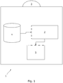
- FIG. 1 A schematic diagram of an autonomous robot in accordance with an embodiment of the invention is shown in Figure 1 .
- the autonomous robot 1 comprises a processor 2.
- the processor 2 may be a single processor system, a dual processor system, or any other suitable processor system.
- the processor 2 is in communication with a camera 3, a inertial sensor 5, and a memory 4 which stores (amongst other things) images captured by the camera 3 and motion data captured by the inertial sensor 5.
- the inertial sensor 5 may be a gyroscope, accelerometer, magnetometer or any other suitable inertial sensor, or indeed a combination of such devices.
- FIG. 3 shows three successive time steps t, t+1 and t+2, where for each time step a "pose" for the autonomous robot 1 is determined, Pose t , Pose t+1 and Pose t+2 respectively, where a pose is a combination of location and heading information (i.e. the direction in which the autonomous robot is facing).
- a pair of images consecutive captured by the camera 3 are obtained (step 21, portion 31 of Figure 3 ).
- Each image is then pre-processed (step 22, portion 32 of Figure 3 ), by subtracting the mean RGB channel values from an example set of images.
- the set of images may be those with which the autonomous robot 1 is trained, for example, as described in detail below.
- the images are resized to be a multiple of 64.
- pre-processing is optional, and in other embodiments does not occur.
- the initial pair of images results in pre-processed images RGBt and RGB t+1
- the pre-processed images are RGB t+1 and RGB t+2 , and so on for the other time steps.
- a convolutional neural network implemented by the processor 2 and memory 4, takes the pair of pre-processed images and uses it to determine features (step 23, portion 33 of Figure 3 ).
- the CNN determines the features in accordance with its training, which has been performed as described below.
- CNNs are a type of neural network that incorporates convolutional layers in the network structure and so, in contrast to fully-connected layers used in other types of neural network, are able to take advantage of the spatial regularity of data. This means that the number of parameters required for the CNN is significantly reduced, allowing them to operate on high-dimensional input (such as raw image data).
- multiple convolutional operations are applied at each convolutional layer, to determine a number of features from the output map of the previous layer.
- the filter kernels with which the maps are convolved are learned during training.
- the CNN takes as input a tensor generated by stacking the pair of pre-processed consecutive images.
- the CNN is composed of nine convolutional layers, each except the last followed by a Rectified Linear Unit (ReLU) non-linearity activation, giving 17 layers in total.
- the layers are configured as follows: Layer Receptive field size Padding Stride Number of channels Conv1 7x7 3 2 64 Conv2 5x5 2 2 128 Conv3 5x5 2 2 256 Conv3_1 3x3 1 1 256 Conv4 3x3 1 2 512 Conv4_1 3x3 1 1 512 Conv5 3x3 1 2 512 Conv5_1 3x3 1 1 512 Conv6 3x3 1 2 1024
- the sizes of the receptive fields in the network gradually reduce from 7 x 7 to 5 x 5 and then 3 x 3, to capture small interesting features.
- Zero-paddings are introduced either to adapt to the configurations of the receptive fields, or to preserve the spatial dimension of the tensor after convolution.
- the number of the channels i.e. the number of filters for feature detection, increases to learn various features.
- the CNN has 55 million trainable weighs, but it will be appreciated that in other embodiments different numbers of weights could be used.
- the features from the final layer i.e. Conv6 are then the output of the CNN.
- a first recurrent neural network takes the motion data from the inertial sensor 5, and uses it to determine features (step 24, portion 34 of Figure 3 ). Similarly to the CNN, the first RNN determines the features in accordance with its training, which has been performed as described below.
- RNNs are a type of neural network in which the layers operate on the input, but also on delayed versions of the hidden layers and/or output. In this way, RNNs have an internal state that they can use as "memory" to keep track of past inputs and corresponding decisions.
- RNNs with a Long Short-Term Memory (LTSM) architecture is used (of which various variations exist), as shown in Figure 4 , in which denotes element-wise product, and ⁇ denotes addition of two vectors.
- the contents of the memory cell is stored in c t .
- the input gate it controls how the input enters into the contents of the memory for the current time-step.
- the forget gate ft determines when the memory cell should be emptied by producing a control signal 0 to 1 which clears the memory cell as needed.
- the output gate o t determines whether the contents of the memory cell should be used at the current time step.
- the parameters W ⁇ ,j and b i fully parameterise the operation of the RNN, and are learned during training.
- the recurrent hidden layer allows the network to make use of the temporal regularity of the input data to improve its performance.
- the LSTM has two layers with cells of 2000 units, but it will be appreciated that in other embodiments different numbers of layers and units could be used.
- the features determined by the CNN and by the first RNN are then passed to a second RNN, which uses them to determine motion features (step 25, portion 35 of Figure 3 ).
- the second RNN takes as input, as well as the hidden state carried over from the previous time step, the pose determined for the previous time step is directly fed to the RNN.
- Figure 3 in which the pose for a time step is fed to the LSTM box for the next time step. The reason for doing this is because, for location estimation, the output is essentially the integration of successive displacements at each time step. Consequently, the determined pose for the previous time step is of particular significance.
- the motion features determined by the RNN are passed to a fully connected layer (step 26), which outputs features of low dimensionality (at least 6 for pose, 6 for uncertainty, and potentially more for each if a mixture of Gaussians is used to estimate pose and uncertainty).
- the low dimensional features from the fully connected layer are passed to an SE(3) layer (step 27, SE3 box of portion 34 of Figure 3 ).
- the SE(3) composes successive motion features for each time step, in order to at each time step determine a location (in fact a pose, such as Pose t for time step t) for the autonomous robot 1.
- quaternionic representations of rotations are used instead of the matrix representations.
- the autonomous robot 1 uses the images from the camera 3 to estimate its location, in particular its pose.
- odometry i.e. odometry
- SLAM Simultaneous Localisation and Mapping
- the output of the fully connected layer is used (before the SE(3) layer). Estimates produced by the fully connected layer are compared with ground truth pose information from training data, resulting in a distribution of errors in pose (location and orientation). A max likelihood approach is then used to train the prediction of the mixture of Gaussian distributions that represents the uncertainty.
- neural networks In order to operate, neural networks of course need to be trained, which is done by providing test data and a cost function to be minimised.
- the system of the present embodiment estimates both pose and uncertainty.
- the test data will be a sequence of images, with "ground truth" poses (i.e. correct poses) for those images.
- the cost function for training is composed of two parts, the first part relating to the pose estimate and the second part relating to the uncertainty estimate.
- pose estimation the first part of the cost function trains the system to minimise the difference between the estimated poses and the ground truth poses.
- the second part of the cost function trains the system by comparing the output of the neural network with pose labels. The training is then done by back-propagation through time, to adjust the weights of the CNN and the first and second RNNs to best minimise the result of the cost function.
- the CNN and the first RNN are both trained to provide the most appropriate features for input to the second RNN, and the second RNN is simultaneously trained to most accurately determine the pose (and uncertainty thereof) of the autonomous robot 1 from those features (and previous determinations).
- the CNN and first RNN in particular are not trained to best provide features of any particular type or with any specific properties; rather they are simply trained to provide features which are best for the operation of the system as a whole.
- the CNN is initially trained in isolation (or otherwise provided with weights that have the effect of such training) to provide features indicative of movement between successive images. This provides an initial state for the CNN, which is then further optimally trained as the system is trained as a whole.
- unsupervised training of the neural networks is performed using correlation.
- training can be done to maximise correlation between the features determined by the CNN from the images and the features determined by the first RNN from the motion data.
- the images suggest a large movement so should the motion data (and vice versa)
- the images suggest a small movement so should the motion data (and vice versa)
- there should be correlation between the features from the CNN and the first RNN, and so training to maximise correlation is advantageous.
Landscapes
- Engineering & Computer Science (AREA)
- Physics & Mathematics (AREA)
- Theoretical Computer Science (AREA)
- General Physics & Mathematics (AREA)
- Computing Systems (AREA)
- Mathematical Physics (AREA)
- Biophysics (AREA)
- Computational Linguistics (AREA)
- Data Mining & Analysis (AREA)
- Evolutionary Computation (AREA)
- General Health & Medical Sciences (AREA)
- Molecular Biology (AREA)
- Artificial Intelligence (AREA)
- General Engineering & Computer Science (AREA)
- Life Sciences & Earth Sciences (AREA)
- Biomedical Technology (AREA)
- Software Systems (AREA)
- Health & Medical Sciences (AREA)
- Computer Vision & Pattern Recognition (AREA)
- Radar, Positioning & Navigation (AREA)
- Remote Sensing (AREA)
- Multimedia (AREA)
- Aviation & Aerospace Engineering (AREA)
- Automation & Control Theory (AREA)
- Electromagnetism (AREA)
- Image Analysis (AREA)
Claims (15)
- Computerimplementiertes Verfahren zum Bestimmen der Position einer Mobilvorrichtung mit einer Kamera und mindestens einem Trägheitssensor, mit folgenden Schritten:Erfassen, unter Verwendung der Kamera, einer Sequenz von Bildern über eine Zeitdauer;für Paare von aufeinanderfolgenden Bildern der Sequenz von Bildern, Bestimmen, unter Verwendung eines faltenden neuronalen Netzes, von Merkmalen, die die Bewegung der Vorrichtung zwischen der Zeit der Erfassung des ersten Bilds des Paars von Bildern und der Zeit der Erfassung des zweiten Bilds des Paars von Bildern angeben;Erfassen, unter Verwendung des mindestens einen Trägheitssensors, von Daten, die die Bewegung der Vorrichtung angeben;Bestimmen, unter Verwendung eines ersten rekurrenten neuronalen Netzes, von Merkmalen, die die Bewegung der Vorrichtung angeben, anhand der Daten, die die Bewegung der Vorrichtung angeben, von dem mindestens einen Trägheitssensor,für die Sequenz von Bildern, Bestimmen, unter Verwendung eines zweiten rekurrenten neuronalen Netzes, von Merkmalen, die die Position der Vorrichtung angeben, anhand der Merkmale, die durch das faltende neuronale Netz und das erste rekurrente neuronale Netz bestimmt wurden; undfür die Sequenz von Bildern, Bestimmen der Position der Vorrichtung anhand der Merkmale, die durch das zweite rekurrente neuronale Netz bestimmt wurden.
- Verfahren nach Anspruch 1, bei dem die Ausrichtung der Vorrichtung zusätzlich zu der Position der Vorrichtung bestimmt wird.
- Verfahren nach Anspruch 1 oder 2, bei dem die Bilder der Sequenz von Bildern monokulare Bilder sind.
- Verfahren nach einem der vorhergehenden Ansprüche, bei dem der mindestens eine Trägheitssensor einen Beschleunigungsmesser und/oder ein Gyroskop aufweist.
- Verfahren nach einem der vorhergehenden Ansprüche, ferner mit dem Schritt Bestimmen, anhand der Merkmale, die durch das erste rekurrente neuronale Netz bestimmt wurden, von relativer Positions- und Ausrichtungsinformation für die Vorrichtung für jedes Paar von aufeinanderfolgenden erfassten Bildern.
- Verfahren nach Anspruch 5, ferner mit dem Schritt Bestimmen von entsprechender Unsicherheitsinformation für die relative Positions- und Ausrichtungsinformation für jedes Paar von aufeinanderfolgenden erfassten Bildern.
- Verfahren nach einem der vorhergehenden Ansprüche, ferner mit dem Schritt Trainieren des faltenden, des ersten rekurrenten und des zweiten rekurrenten neuronalen Netzes zum Maximieren der Korrelation zwischen den Merkmalen, die durch das faltende neuronale Netz bestimmt werden, und den Merkmalen, die durch das erste rekurrente neuronale Netz bestimmt werden.
- Verfahren nach einem der vorherigen Ansprüche, bei dem die Vorrichtung ein autonomer Roboter ist.
- Mobilvorrichtung mit:einem Speicher;einem Prozessor;einer Kamera;mindestens einem Trägheitssensor; bei der die Vorrichtung angeordnet ist zum:Erfassen, unter Verwendung der Kamera, einer Sequenz von Bildern über eine Zeitdauer;für Paare von aufeinanderfolgenden Bildern der Sequenz von Bildern, Bestimmen, unter Verwendung eines faltenden neuronalen Netzes, von Merkmalen, die die Bewegung der Vorrichtung zwischen der Zeit der Erfassung des ersten Bilds des Paars von Bildern und der Zeit der Erfassung des zweiten Bilds des Paars von Bildern angeben;Erfassen, unter Verwendung des mindestens einen Trägheitssensors, von Daten, die die Bewegung der Vorrichtung angeben;Bestimmen, unter Verwendung eines ersten rekurrenten neuronalen Netzes, von Merkmalen, die die Bewegung der Vorrichtung angeben, anhand der Daten, die die Bewegung der Vorrichtung angeben, von dem mindestens einen Trägheitssensor,für die Sequenz von Bildern, Bestimmen, unter Verwendung eines zweiten rekurrenten neuronalen Netzes, von Merkmalen, die die Position der Vorrichtung angeben, anhand der Merkmale, die durch das faltende neuronale Netz und das erste rekurrente neuronale Netz bestimmt wurden; undfür die Sequenz von Bildern, Bestimmen der Position der Vorrichtung anhand der Merkmale, die durch das zweite rekurrente neuronale Netz bestimmt wurden.
- Vorrichtung nach Anspruch 9, bei der die Vorrichtung zum Bestimmen der Ausrichtung der Vorrichtung zusätzlich zu der Position der Vorrichtung angeordnet ist.
- Vorrichtung nach Anspruch 9 oder 10, bei der die Bilder der Sequenz von Bildern monokulare Bilder sind.
- Vorrichtung nach einem der Ansprüche 9 bis 11, bei der der mindestens eine Trägheitssensor einen Beschleunigungsmesser und/oder ein Gyroskop aufweist.
- Vorrichtung nach Anspruch 10, ferner angeordnet zum Bestimmen von entsprechender Unsicherheitsinformation für die relative Positions- und Ausrichtungsinformation für jedes Paar von aufeinanderfolgenden erfassten Bildern.
- Computerprogrammprodukt, das angeordnet ist zum Durchführen des Verfahrens nach einem der Ansprüche 1 bis 8 bei einer Ausführung auf einer Mobilvorrichtung.
- Computerprogrammprodukt, das angeordnet ist zum Bereitstellen einer Mobilvorrichtung nach einem der Ansprüche 9 bis 13 bei einer Ausführung auf einer Mobilvorrichtung.
Applications Claiming Priority (3)
| Application Number | Priority Date | Filing Date | Title |
|---|---|---|---|
| GR20170100023 | 2017-01-23 | ||
| GBGB1703006.5A GB201703006D0 (en) | 2017-02-24 | 2017-02-24 | Determining the location of a mobile device |
| PCT/GB2018/050132 WO2018134587A1 (en) | 2017-01-23 | 2018-01-17 | Determining the location of a mobile device |
Publications (2)
| Publication Number | Publication Date |
|---|---|
| EP3571664A1 EP3571664A1 (de) | 2019-11-27 |
| EP3571664B1 true EP3571664B1 (de) | 2021-05-12 |
Family
ID=61022369
Family Applications (1)
| Application Number | Title | Priority Date | Filing Date |
|---|---|---|---|
| EP18701218.2A Active EP3571664B1 (de) | 2017-01-23 | 2018-01-17 | Bestimmung des standorts einer mobilen vorrichtung |
Country Status (6)
| Country | Link |
|---|---|
| US (1) | US11348274B2 (de) |
| EP (1) | EP3571664B1 (de) |
| JP (1) | JP7121017B2 (de) |
| CN (1) | CN110770758B (de) |
| AU (1) | AU2018209336B2 (de) |
| WO (1) | WO2018134587A1 (de) |
Families Citing this family (16)
| Publication number | Priority date | Publication date | Assignee | Title |
|---|---|---|---|---|
| GB201804079D0 (en) | 2018-01-10 | 2018-04-25 | Univ Oxford Innovation Ltd | Determining the location of a mobile device |
| US11254002B1 (en) * | 2018-03-19 | 2022-02-22 | AI Incorporated | Autonomous robotic device |
| CN110706194B (zh) * | 2018-06-21 | 2021-07-06 | 北京三快在线科技有限公司 | 一种定位方法、装置及移动设备 |
| US12122420B2 (en) * | 2018-08-29 | 2024-10-22 | Intel Corporation | Computer vision system |
| EP3966742A1 (de) * | 2019-05-06 | 2022-03-16 | Zenuity AB | Automatisierte kartenherstellung und positionierung |
| CN112001968B (zh) * | 2019-05-27 | 2022-07-15 | 浙江商汤科技开发有限公司 | 相机定位方法及装置、存储介质 |
| US10989916B2 (en) * | 2019-08-20 | 2021-04-27 | Google Llc | Pose prediction with recurrent neural networks |
| CN114402335B (zh) * | 2019-09-11 | 2025-07-11 | 维萨国际服务协会 | 用于管理模型更新的方法、系统和计算机程序产品 |
| US11032665B1 (en) * | 2020-02-25 | 2021-06-08 | At&T Intellectual Property I, L.P. | User equipment geolocation |
| CN111428116B (zh) * | 2020-06-08 | 2021-01-12 | 四川大学 | 一种基于深度神经网络的微博社交机器人检测方法 |
| US20220075378A1 (en) * | 2020-06-23 | 2022-03-10 | California Institute Of Technology | Aircraft-based visual-inertial odometry with range measurement for drift reduction |
| DE102020210376A1 (de) * | 2020-08-14 | 2022-02-17 | Robert Bosch Gesellschaft mit beschränkter Haftung | Vorrichtung und Verfahren zum Steuern eines Hardware-Agenten in einer Steuersituation mit mehreren Hardware-Agenten |
| CN112212867B (zh) * | 2020-10-19 | 2024-05-28 | 中国科学技术大学 | 一种机器人自定位与导航的方法及系统 |
| CN112561947A (zh) * | 2020-12-10 | 2021-03-26 | 中国科学院深圳先进技术研究院 | 一种图像自适应运动估计方法及应用 |
| US11809521B2 (en) * | 2021-06-08 | 2023-11-07 | Fanuc Corporation | Network modularization to learn high dimensional robot tasks |
| EP4356786A1 (de) * | 2022-10-20 | 2024-04-24 | Koninklijke Philips N.V. | Lokalisierungsverfahren für eine körperpflegevorrichtung |
Family Cites Families (43)
| Publication number | Priority date | Publication date | Assignee | Title |
|---|---|---|---|---|
| DE4419925A1 (de) | 1994-06-08 | 1995-12-14 | Bodenseewerk Geraetetech | Inertialsensor-Einheit |
| CA2184563A1 (en) * | 1995-09-18 | 1997-03-19 | Theo C. Giras | Vehicle navigator system |
| JP3655033B2 (ja) * | 1996-12-10 | 2005-06-02 | 株式会社リコー | 携帯型情報処理装置及び携帯型情報処理装置の場所識別方法 |
| JPH11110542A (ja) * | 1997-09-30 | 1999-04-23 | Toshiba Corp | パターン抽出方法および装置、そのプログラムを記録した媒体 |
| US6704621B1 (en) | 1999-11-26 | 2004-03-09 | Gideon P. Stein | System and method for estimating ego-motion of a moving vehicle using successive images recorded along the vehicle's path of motion |
| US7272467B2 (en) * | 2002-12-17 | 2007-09-18 | Evolution Robotics, Inc. | Systems and methods for filtering potentially unreliable visual data for visual simultaneous localization and mapping |
| CA2442950A1 (en) * | 2003-09-26 | 2005-03-26 | Chahe Nerguizian | Method and system for indoor geolocation using an impulse response fingerprinting technique |
| US7860301B2 (en) | 2005-02-11 | 2010-12-28 | Macdonald Dettwiler And Associates Inc. | 3D imaging system |
| US7925049B2 (en) | 2006-08-15 | 2011-04-12 | Sri International | Stereo-based visual odometry method and system |
| US20080195316A1 (en) | 2007-02-12 | 2008-08-14 | Honeywell International Inc. | System and method for motion estimation using vision sensors |
| US9766074B2 (en) | 2008-03-28 | 2017-09-19 | Regents Of The University Of Minnesota | Vision-aided inertial navigation |
| US8213706B2 (en) | 2008-04-22 | 2012-07-03 | Honeywell International Inc. | Method and system for real-time visual odometry |
| JP6002126B2 (ja) * | 2010-06-25 | 2016-10-05 | トリンブル ナビゲーション リミテッドTrimble Navigation Limited | 画像ベースの測位のための方法および装置 |
| US8259994B1 (en) | 2010-09-14 | 2012-09-04 | Google Inc. | Using image and laser constraints to obtain consistent and improved pose estimates in vehicle pose databases |
| CN102042835B (zh) * | 2010-11-05 | 2012-10-24 | 中国海洋大学 | 自主式水下机器人组合导航系统 |
| US8761439B1 (en) | 2011-08-24 | 2014-06-24 | Sri International | Method and apparatus for generating three-dimensional pose using monocular visual sensor and inertial measurement unit |
| US9148650B2 (en) | 2012-09-17 | 2015-09-29 | Nec Laboratories America, Inc. | Real-time monocular visual odometry |
| US9576183B2 (en) | 2012-11-02 | 2017-02-21 | Qualcomm Incorporated | Fast initialization for monocular visual SLAM |
| US10254118B2 (en) | 2013-02-21 | 2019-04-09 | Regents Of The University Of Minnesota | Extrinsic parameter calibration of a vision-aided inertial navigation system |
| US9674507B2 (en) | 2013-04-30 | 2017-06-06 | Qualcomm Incorporated | Monocular visual SLAM with general and panorama camera movements |
| US20140341465A1 (en) | 2013-05-16 | 2014-11-20 | The Regents Of The University Of California | Real-time pose estimation system using inertial and feature measurements |
| US10306206B2 (en) | 2013-07-23 | 2019-05-28 | The Regents Of The University Of California | 3-D motion estimation and online temporal calibration for camera-IMU systems |
| US10247556B2 (en) | 2013-07-23 | 2019-04-02 | The Regents Of The University Of California | Method for processing feature measurements in vision-aided inertial navigation |
| EP3025275A4 (de) | 2013-07-24 | 2017-02-15 | The Regents Of The University Of California | Verfahren zur schätzung und korrektur von kamerabewegungen |
| EP2854104A1 (de) | 2013-09-25 | 2015-04-01 | Technische Universität München | Semi-dichte simultane Ortung und Kartierung |
| US9243915B2 (en) | 2013-10-16 | 2016-01-26 | Physical Devices, Llc | Devices and methods for passive navigation |
| US10670402B2 (en) * | 2013-11-01 | 2020-06-02 | Invensense, Inc. | Systems and methods for optical sensor navigation |
| US9390344B2 (en) | 2014-01-09 | 2016-07-12 | Qualcomm Incorporated | Sensor-based camera motion detection for unconstrained slam |
| CN103983263A (zh) | 2014-05-30 | 2014-08-13 | 东南大学 | 一种采用迭代扩展卡尔曼滤波与神经网络的惯性/视觉组合导航方法 |
| US9430847B2 (en) | 2014-06-12 | 2016-08-30 | Mitsubishi Electric Research Laboratories, Inc. | Method for stereo visual odometry using points, lines and planes |
| EP3699736B1 (de) * | 2014-06-14 | 2023-03-29 | Magic Leap, Inc. | Verfahren und system zur erzeugung von virtueller und erweiterter realität |
| US9798322B2 (en) * | 2014-06-19 | 2017-10-24 | Skydio, Inc. | Virtual camera interface and other user interaction paradigms for a flying digital assistant |
| US10113910B2 (en) | 2014-08-26 | 2018-10-30 | Digimarc Corporation | Sensor-synchronized spectrally-structured-light imaging |
| US9630318B2 (en) * | 2014-10-02 | 2017-04-25 | Brain Corporation | Feature detection apparatus and methods for training of robotic navigation |
| US9709404B2 (en) | 2015-04-17 | 2017-07-18 | Regents Of The University Of Minnesota | Iterative Kalman Smoother for robust 3D localization for vision-aided inertial navigation |
| US9902401B2 (en) | 2015-05-10 | 2018-02-27 | Mobileye Vision Technologies Ltd. | Road profile along a predicted path |
| US9811734B2 (en) * | 2015-05-11 | 2017-11-07 | Google Inc. | Crowd-sourced creation and updating of area description file for mobile device localization |
| CN107850436B (zh) | 2015-05-23 | 2021-03-05 | 深圳市大疆创新科技有限公司 | 使用惯性传感器和图像传感器的传感器融合 |
| EP3182373B1 (de) | 2015-12-17 | 2019-06-19 | STMicroelectronics S.A. | Verbesserungen bei der bestimmung einer egobewegung einer videovorrichtung in einem slam-algorithmus |
| CN106017458B (zh) | 2016-05-18 | 2019-08-27 | 宁波华狮智能科技有限公司 | 移动机器人组合式导航方法及装置 |
| US10453213B2 (en) * | 2016-08-29 | 2019-10-22 | Trifo, Inc. | Mapping optimization in autonomous and non-autonomous platforms |
| US10395117B1 (en) * | 2016-08-29 | 2019-08-27 | Trifo, Inc. | Visual-inertial positional awareness for autonomous and non-autonomous tracking |
| WO2018090308A1 (en) * | 2016-11-18 | 2018-05-24 | Intel Corporation | Enhanced localization method and apparatus |
-
2018
- 2018-01-17 EP EP18701218.2A patent/EP3571664B1/de active Active
- 2018-01-17 WO PCT/GB2018/050132 patent/WO2018134587A1/en not_active Ceased
- 2018-01-17 AU AU2018209336A patent/AU2018209336B2/en active Active
- 2018-01-17 CN CN201880020559.7A patent/CN110770758B/zh active Active
- 2018-01-17 US US16/479,855 patent/US11348274B2/en active Active
- 2018-01-17 JP JP2019539805A patent/JP7121017B2/ja active Active
Also Published As
| Publication number | Publication date |
|---|---|
| WO2018134587A1 (en) | 2018-07-26 |
| JP2020505695A (ja) | 2020-02-20 |
| EP3571664A1 (de) | 2019-11-27 |
| AU2018209336A1 (en) | 2019-08-15 |
| CN110770758A (zh) | 2020-02-07 |
| US20210407122A1 (en) | 2021-12-30 |
| AU2018209336B2 (en) | 2021-11-18 |
| US11348274B2 (en) | 2022-05-31 |
| JP7121017B2 (ja) | 2022-08-17 |
| CN110770758B (zh) | 2024-06-04 |
Similar Documents
| Publication | Publication Date | Title |
|---|---|---|
| EP3571664B1 (de) | Bestimmung des standorts einer mobilen vorrichtung | |
| Clark et al. | Vinet: Visual-inertial odometry as a sequence-to-sequence learning problem | |
| Yang et al. | Concrete defects inspection and 3D mapping using CityFlyer quadrotor robot | |
| US11734918B2 (en) | Object identification apparatus, moving body system, object identification method, object identification model learning method, and object identification model learning apparatus | |
| EP3752955B1 (de) | Bildsegmentierung | |
| Ding et al. | Vehicle pose and shape estimation through multiple monocular vision | |
| Gao et al. | Gyro-Net: IMU gyroscopes random errors compensation method based on deep learning | |
| EP3571665B1 (de) | Bestimmung des standorts einer mobilen vorrichtung | |
| US20210078587A1 (en) | Ballistic estimation of vehicle data | |
| White et al. | GPS-denied navigation using SAR images and neural networks | |
| CN114792414A (zh) | 一种用于载体的目标变量检测方法及其系统 | |
| Song et al. | 2d lidar map prediction via estimating motion flow with gru | |
| Agostinho et al. | TEFu-Net: A time-aware late fusion architecture for robust multi-modal ego-motion estimation | |
| CN117314968B (zh) | 运动信息估计方法、装置、设备、存储介质和程序产品 | |
| Jantos et al. | AI-based multi-object relative state estimation with self-calibration capabilities | |
| Chawla et al. | Error diagnosis of deep monocular depth estimation models | |
| CN114693988B (zh) | 卫星自主位姿的判定方法、系统及存储介质 | |
| CN117727002A (zh) | 基于多任务神经网络的交通场景分割与视觉里程计方法 | |
| HK40010223B (en) | Determining the location of a mobile device | |
| KR20200027078A (ko) | Cnn을 이용하여 크기 독립적으로 물체를 검출하는 방법 및 장치 | |
| HK40010222B (en) | Determining the location of a mobile device | |
| HK40010222A (en) | Determining the location of a mobile device | |
| Sun et al. | TransFusionOdom: Interpretable transformer-based LiDAR-inertial fusion odometry estimation | |
| CN119832176B (zh) | 一种基于多目视觉场景理解的无人系统自主探索方法 | |
| Medarametla et al. | Real-Time Localization Framework for Autonomous Basketball Robots |
Legal Events
| Date | Code | Title | Description |
|---|---|---|---|
| STAA | Information on the status of an ep patent application or granted ep patent |
Free format text: STATUS: UNKNOWN |
|
| STAA | Information on the status of an ep patent application or granted ep patent |
Free format text: STATUS: THE INTERNATIONAL PUBLICATION HAS BEEN MADE |
|
| PUAI | Public reference made under article 153(3) epc to a published international application that has entered the european phase |
Free format text: ORIGINAL CODE: 0009012 |
|
| STAA | Information on the status of an ep patent application or granted ep patent |
Free format text: STATUS: REQUEST FOR EXAMINATION WAS MADE |
|
| 17P | Request for examination filed |
Effective date: 20190730 |
|
| AK | Designated contracting states |
Kind code of ref document: A1 Designated state(s): AL AT BE BG CH CY CZ DE DK EE ES FI FR GB GR HR HU IE IS IT LI LT LU LV MC MK MT NL NO PL PT RO RS SE SI SK SM TR |
|
| AX | Request for extension of the european patent |
Extension state: BA ME |
|
| DAV | Request for validation of the european patent (deleted) | ||
| DAX | Request for extension of the european patent (deleted) | ||
| REG | Reference to a national code |
Ref country code: HK Ref legal event code: DE Ref document number: 40010223 Country of ref document: HK |
|
| GRAP | Despatch of communication of intention to grant a patent |
Free format text: ORIGINAL CODE: EPIDOSNIGR1 |
|
| STAA | Information on the status of an ep patent application or granted ep patent |
Free format text: STATUS: GRANT OF PATENT IS INTENDED |
|
| RIC1 | Information provided on ipc code assigned before grant |
Ipc: G06T 7/20 20170101AFI20201030BHEP Ipc: G06T 7/70 20170101ALI20201030BHEP Ipc: G06N 3/08 20060101ALI20201030BHEP Ipc: G06N 3/04 20060101ALI20201030BHEP |
|
| INTG | Intention to grant announced |
Effective date: 20201127 |
|
| GRAS | Grant fee paid |
Free format text: ORIGINAL CODE: EPIDOSNIGR3 |
|
| GRAA | (expected) grant |
Free format text: ORIGINAL CODE: 0009210 |
|
| STAA | Information on the status of an ep patent application or granted ep patent |
Free format text: STATUS: THE PATENT HAS BEEN GRANTED |
|
| AK | Designated contracting states |
Kind code of ref document: B1 Designated state(s): AL AT BE BG CH CY CZ DE DK EE ES FI FR GB GR HR HU IE IS IT LI LT LU LV MC MK MT NL NO PL PT RO RS SE SI SK SM TR |
|
| REG | Reference to a national code |
Ref country code: GB Ref legal event code: FG4D |
|
| REG | Reference to a national code |
Ref country code: CH Ref legal event code: EP |
|
| REG | Reference to a national code |
Ref country code: DE Ref legal event code: R096 Ref document number: 602018017004 Country of ref document: DE |
|
| REG | Reference to a national code |
Ref country code: IE Ref legal event code: FG4D |
|
| REG | Reference to a national code |
Ref country code: AT Ref legal event code: REF Ref document number: 1392681 Country of ref document: AT Kind code of ref document: T Effective date: 20210615 |
|
| REG | Reference to a national code |
Ref country code: LT Ref legal event code: MG9D |
|
| REG | Reference to a national code |
Ref country code: AT Ref legal event code: MK05 Ref document number: 1392681 Country of ref document: AT Kind code of ref document: T Effective date: 20210512 |
|
| REG | Reference to a national code |
Ref country code: NL Ref legal event code: MP Effective date: 20210512 |
|
| PG25 | Lapsed in a contracting state [announced via postgrant information from national office to epo] |
Ref country code: HR Free format text: LAPSE BECAUSE OF FAILURE TO SUBMIT A TRANSLATION OF THE DESCRIPTION OR TO PAY THE FEE WITHIN THE PRESCRIBED TIME-LIMIT Effective date: 20210512 Ref country code: LT Free format text: LAPSE BECAUSE OF FAILURE TO SUBMIT A TRANSLATION OF THE DESCRIPTION OR TO PAY THE FEE WITHIN THE PRESCRIBED TIME-LIMIT Effective date: 20210512 Ref country code: FI Free format text: LAPSE BECAUSE OF FAILURE TO SUBMIT A TRANSLATION OF THE DESCRIPTION OR TO PAY THE FEE WITHIN THE PRESCRIBED TIME-LIMIT Effective date: 20210512 Ref country code: AT Free format text: LAPSE BECAUSE OF FAILURE TO SUBMIT A TRANSLATION OF THE DESCRIPTION OR TO PAY THE FEE WITHIN THE PRESCRIBED TIME-LIMIT Effective date: 20210512 Ref country code: BG Free format text: LAPSE BECAUSE OF FAILURE TO SUBMIT A TRANSLATION OF THE DESCRIPTION OR TO PAY THE FEE WITHIN THE PRESCRIBED TIME-LIMIT Effective date: 20210812 |
|
| PG25 | Lapsed in a contracting state [announced via postgrant information from national office to epo] |
Ref country code: SE Free format text: LAPSE BECAUSE OF FAILURE TO SUBMIT A TRANSLATION OF THE DESCRIPTION OR TO PAY THE FEE WITHIN THE PRESCRIBED TIME-LIMIT Effective date: 20210512 Ref country code: RS Free format text: LAPSE BECAUSE OF FAILURE TO SUBMIT A TRANSLATION OF THE DESCRIPTION OR TO PAY THE FEE WITHIN THE PRESCRIBED TIME-LIMIT Effective date: 20210512 Ref country code: NO Free format text: LAPSE BECAUSE OF FAILURE TO SUBMIT A TRANSLATION OF THE DESCRIPTION OR TO PAY THE FEE WITHIN THE PRESCRIBED TIME-LIMIT Effective date: 20210812 Ref country code: PL Free format text: LAPSE BECAUSE OF FAILURE TO SUBMIT A TRANSLATION OF THE DESCRIPTION OR TO PAY THE FEE WITHIN THE PRESCRIBED TIME-LIMIT Effective date: 20210512 Ref country code: LV Free format text: LAPSE BECAUSE OF FAILURE TO SUBMIT A TRANSLATION OF THE DESCRIPTION OR TO PAY THE FEE WITHIN THE PRESCRIBED TIME-LIMIT Effective date: 20210512 Ref country code: PT Free format text: LAPSE BECAUSE OF FAILURE TO SUBMIT A TRANSLATION OF THE DESCRIPTION OR TO PAY THE FEE WITHIN THE PRESCRIBED TIME-LIMIT Effective date: 20210913 Ref country code: GR Free format text: LAPSE BECAUSE OF FAILURE TO SUBMIT A TRANSLATION OF THE DESCRIPTION OR TO PAY THE FEE WITHIN THE PRESCRIBED TIME-LIMIT Effective date: 20210813 Ref country code: IS Free format text: LAPSE BECAUSE OF FAILURE TO SUBMIT A TRANSLATION OF THE DESCRIPTION OR TO PAY THE FEE WITHIN THE PRESCRIBED TIME-LIMIT Effective date: 20210912 |
|
| PG25 | Lapsed in a contracting state [announced via postgrant information from national office to epo] |
Ref country code: NL Free format text: LAPSE BECAUSE OF FAILURE TO SUBMIT A TRANSLATION OF THE DESCRIPTION OR TO PAY THE FEE WITHIN THE PRESCRIBED TIME-LIMIT Effective date: 20210512 |
|
| PG25 | Lapsed in a contracting state [announced via postgrant information from national office to epo] |
Ref country code: RO Free format text: LAPSE BECAUSE OF FAILURE TO SUBMIT A TRANSLATION OF THE DESCRIPTION OR TO PAY THE FEE WITHIN THE PRESCRIBED TIME-LIMIT Effective date: 20210512 Ref country code: CZ Free format text: LAPSE BECAUSE OF FAILURE TO SUBMIT A TRANSLATION OF THE DESCRIPTION OR TO PAY THE FEE WITHIN THE PRESCRIBED TIME-LIMIT Effective date: 20210512 Ref country code: DK Free format text: LAPSE BECAUSE OF FAILURE TO SUBMIT A TRANSLATION OF THE DESCRIPTION OR TO PAY THE FEE WITHIN THE PRESCRIBED TIME-LIMIT Effective date: 20210512 Ref country code: SM Free format text: LAPSE BECAUSE OF FAILURE TO SUBMIT A TRANSLATION OF THE DESCRIPTION OR TO PAY THE FEE WITHIN THE PRESCRIBED TIME-LIMIT Effective date: 20210512 Ref country code: SK Free format text: LAPSE BECAUSE OF FAILURE TO SUBMIT A TRANSLATION OF THE DESCRIPTION OR TO PAY THE FEE WITHIN THE PRESCRIBED TIME-LIMIT Effective date: 20210512 Ref country code: EE Free format text: LAPSE BECAUSE OF FAILURE TO SUBMIT A TRANSLATION OF THE DESCRIPTION OR TO PAY THE FEE WITHIN THE PRESCRIBED TIME-LIMIT Effective date: 20210512 Ref country code: ES Free format text: LAPSE BECAUSE OF FAILURE TO SUBMIT A TRANSLATION OF THE DESCRIPTION OR TO PAY THE FEE WITHIN THE PRESCRIBED TIME-LIMIT Effective date: 20210512 |
|
| REG | Reference to a national code |
Ref country code: DE Ref legal event code: R097 Ref document number: 602018017004 Country of ref document: DE |
|
| PLBE | No opposition filed within time limit |
Free format text: ORIGINAL CODE: 0009261 |
|
| STAA | Information on the status of an ep patent application or granted ep patent |
Free format text: STATUS: NO OPPOSITION FILED WITHIN TIME LIMIT |
|
| 26N | No opposition filed |
Effective date: 20220215 |
|
| PG25 | Lapsed in a contracting state [announced via postgrant information from national office to epo] |
Ref country code: IS Free format text: LAPSE BECAUSE OF FAILURE TO SUBMIT A TRANSLATION OF THE DESCRIPTION OR TO PAY THE FEE WITHIN THE PRESCRIBED TIME-LIMIT Effective date: 20210912 Ref country code: AL Free format text: LAPSE BECAUSE OF FAILURE TO SUBMIT A TRANSLATION OF THE DESCRIPTION OR TO PAY THE FEE WITHIN THE PRESCRIBED TIME-LIMIT Effective date: 20210512 |
|
| PG25 | Lapsed in a contracting state [announced via postgrant information from national office to epo] |
Ref country code: IT Free format text: LAPSE BECAUSE OF FAILURE TO SUBMIT A TRANSLATION OF THE DESCRIPTION OR TO PAY THE FEE WITHIN THE PRESCRIBED TIME-LIMIT Effective date: 20210512 |
|
| PG25 | Lapsed in a contracting state [announced via postgrant information from national office to epo] |
Ref country code: MC Free format text: LAPSE BECAUSE OF FAILURE TO SUBMIT A TRANSLATION OF THE DESCRIPTION OR TO PAY THE FEE WITHIN THE PRESCRIBED TIME-LIMIT Effective date: 20210512 |
|
| REG | Reference to a national code |
Ref country code: CH Ref legal event code: PL |
|
| REG | Reference to a national code |
Ref country code: BE Ref legal event code: MM Effective date: 20220131 |
|
| PG25 | Lapsed in a contracting state [announced via postgrant information from national office to epo] |
Ref country code: LU Free format text: LAPSE BECAUSE OF NON-PAYMENT OF DUE FEES Effective date: 20220117 |
|
| PG25 | Lapsed in a contracting state [announced via postgrant information from national office to epo] |
Ref country code: BE Free format text: LAPSE BECAUSE OF NON-PAYMENT OF DUE FEES Effective date: 20220131 |
|
| PG25 | Lapsed in a contracting state [announced via postgrant information from national office to epo] |
Ref country code: LI Free format text: LAPSE BECAUSE OF NON-PAYMENT OF DUE FEES Effective date: 20220131 Ref country code: CH Free format text: LAPSE BECAUSE OF NON-PAYMENT OF DUE FEES Effective date: 20220131 |
|
| PG25 | Lapsed in a contracting state [announced via postgrant information from national office to epo] |
Ref country code: IE Free format text: LAPSE BECAUSE OF NON-PAYMENT OF DUE FEES Effective date: 20220117 |
|
| P01 | Opt-out of the competence of the unified patent court (upc) registered |
Effective date: 20230517 |
|
| PG25 | Lapsed in a contracting state [announced via postgrant information from national office to epo] |
Ref country code: MK Free format text: LAPSE BECAUSE OF FAILURE TO SUBMIT A TRANSLATION OF THE DESCRIPTION OR TO PAY THE FEE WITHIN THE PRESCRIBED TIME-LIMIT Effective date: 20210512 Ref country code: CY Free format text: LAPSE BECAUSE OF FAILURE TO SUBMIT A TRANSLATION OF THE DESCRIPTION OR TO PAY THE FEE WITHIN THE PRESCRIBED TIME-LIMIT Effective date: 20210512 |
|
| PG25 | Lapsed in a contracting state [announced via postgrant information from national office to epo] |
Ref country code: HU Free format text: LAPSE BECAUSE OF FAILURE TO SUBMIT A TRANSLATION OF THE DESCRIPTION OR TO PAY THE FEE WITHIN THE PRESCRIBED TIME-LIMIT; INVALID AB INITIO Effective date: 20180117 |
|
| PG25 | Lapsed in a contracting state [announced via postgrant information from national office to epo] |
Ref country code: MT Free format text: LAPSE BECAUSE OF FAILURE TO SUBMIT A TRANSLATION OF THE DESCRIPTION OR TO PAY THE FEE WITHIN THE PRESCRIBED TIME-LIMIT Effective date: 20210512 |
|
| PGFP | Annual fee paid to national office [announced via postgrant information from national office to epo] |
Ref country code: DE Payment date: 20250120 Year of fee payment: 8 |
|
| PG25 | Lapsed in a contracting state [announced via postgrant information from national office to epo] |
Ref country code: TR Free format text: LAPSE BECAUSE OF FAILURE TO SUBMIT A TRANSLATION OF THE DESCRIPTION OR TO PAY THE FEE WITHIN THE PRESCRIBED TIME-LIMIT Effective date: 20210512 |
|
| PGFP | Annual fee paid to national office [announced via postgrant information from national office to epo] |
Ref country code: GB Payment date: 20251219 Year of fee payment: 9 |
|
| PGFP | Annual fee paid to national office [announced via postgrant information from national office to epo] |
Ref country code: FR Payment date: 20251218 Year of fee payment: 9 |