EP3571402B1 - Nacelle of a wind power plant - Google Patents
Nacelle of a wind power plant Download PDFInfo
- Publication number
- EP3571402B1 EP3571402B1 EP18700128.4A EP18700128A EP3571402B1 EP 3571402 B1 EP3571402 B1 EP 3571402B1 EP 18700128 A EP18700128 A EP 18700128A EP 3571402 B1 EP3571402 B1 EP 3571402B1
- Authority
- EP
- European Patent Office
- Prior art keywords
- nacelle
- cooling
- housing
- component
- cooling fin
- Prior art date
- Legal status (The legal status is an assumption and is not a legal conclusion. Google has not performed a legal analysis and makes no representation as to the accuracy of the status listed.)
- Active
Links
- 238000001816 cooling Methods 0.000 claims description 117
- 239000002184 metal Substances 0.000 description 4
- 238000012423 maintenance Methods 0.000 description 3
- 230000005540 biological transmission Effects 0.000 description 2
- 230000000694 effects Effects 0.000 description 2
- 230000017525 heat dissipation Effects 0.000 description 2
- 230000008439 repair process Effects 0.000 description 2
- 239000004020 conductor Substances 0.000 description 1
- 238000009434 installation Methods 0.000 description 1
- 238000004519 manufacturing process Methods 0.000 description 1
- 238000003466 welding Methods 0.000 description 1
Images

Classifications
-
- F—MECHANICAL ENGINEERING; LIGHTING; HEATING; WEAPONS; BLASTING
- F03—MACHINES OR ENGINES FOR LIQUIDS; WIND, SPRING, OR WEIGHT MOTORS; PRODUCING MECHANICAL POWER OR A REACTIVE PROPULSIVE THRUST, NOT OTHERWISE PROVIDED FOR
- F03D—WIND MOTORS
- F03D80/00—Details, components or accessories not provided for in groups F03D1/00 - F03D17/00
- F03D80/60—Cooling or heating of wind motors
-
- F—MECHANICAL ENGINEERING; LIGHTING; HEATING; WEAPONS; BLASTING
- F05—INDEXING SCHEMES RELATING TO ENGINES OR PUMPS IN VARIOUS SUBCLASSES OF CLASSES F01-F04
- F05B—INDEXING SCHEME RELATING TO WIND, SPRING, WEIGHT, INERTIA OR LIKE MOTORS, TO MACHINES OR ENGINES FOR LIQUIDS COVERED BY SUBCLASSES F03B, F03D AND F03G
- F05B2240/00—Components
- F05B2240/10—Stators
- F05B2240/14—Casings, housings, nacelles, gondels or the like, protecting or supporting assemblies there within
-
- F—MECHANICAL ENGINEERING; LIGHTING; HEATING; WEAPONS; BLASTING
- F05—INDEXING SCHEMES RELATING TO ENGINES OR PUMPS IN VARIOUS SUBCLASSES OF CLASSES F01-F04
- F05B—INDEXING SCHEME RELATING TO WIND, SPRING, WEIGHT, INERTIA OR LIKE MOTORS, TO MACHINES OR ENGINES FOR LIQUIDS COVERED BY SUBCLASSES F03B, F03D AND F03G
- F05B2260/00—Function
- F05B2260/20—Heat transfer, e.g. cooling
- F05B2260/221—Improvement of heat transfer
- F05B2260/224—Improvement of heat transfer by increasing the heat transfer surface
- F05B2260/2241—Improvement of heat transfer by increasing the heat transfer surface using fins or ribs
-
- Y—GENERAL TAGGING OF NEW TECHNOLOGICAL DEVELOPMENTS; GENERAL TAGGING OF CROSS-SECTIONAL TECHNOLOGIES SPANNING OVER SEVERAL SECTIONS OF THE IPC; TECHNICAL SUBJECTS COVERED BY FORMER USPC CROSS-REFERENCE ART COLLECTIONS [XRACs] AND DIGESTS
- Y02—TECHNOLOGIES OR APPLICATIONS FOR MITIGATION OR ADAPTATION AGAINST CLIMATE CHANGE
- Y02E—REDUCTION OF GREENHOUSE GAS [GHG] EMISSIONS, RELATED TO ENERGY GENERATION, TRANSMISSION OR DISTRIBUTION
- Y02E10/00—Energy generation through renewable energy sources
- Y02E10/70—Wind energy
- Y02E10/72—Wind turbines with rotation axis in wind direction
Definitions
- the invention relates to a nacelle of a wind power plant, the nacelle comprising at least one housing with an outside and an inside and at least one component that is arranged inside the housing and is to be cooled.
- the invention also relates to a wind power plant with the nacelle and a use.
- a wind energy system can comprise one or more wind turbines that are connected to an (offshore) transformer station, for example.
- a wind turbine generally includes a rotor with a hub and with a plurality of rotor blades (e.g. three).
- the rotor is connected to a nacelle (also called a machine nacelle).
- the gondola is usually rotatably mounted on a tower.
- the nacelle has a housing.
- the housing can comprise at least one component to be cooled, such as an electrical component and / or a mechanical component.
- an electrical component is a component that is operated with an electrical variable and / or generates an electrical variable.
- the nacelle can comprise at least one transformer as an electrical component.
- This is usually provided with a housing or arranged in a transformer housing, which in turn is arranged in the housing of the nacelle.
- the same applies to other components to be cooled. Due to the losses or power loss, such a transformer must be cooled.
- Complex cooling systems for cooling the at least one component are installed in prior art nacelles.
- the known cooling systems have in common that they are active cooling systems. Active cooling systems are characterized by the fact that they transport the heat away from the component to be cooled with the help of a fan or a pump.
- the invention is therefore based on the object of providing a nacelle for a wind power plant which enables sufficient, in particular improved, cooling of at least one electrical component of the nacelle in a simpler manner.
- the object is achieved by a nacelle of a wind power plant according to claim 1.
- the nacelle comprises at least one housing with an outside and an inside.
- the nacelle comprises at least one component that is arranged within the housing and is to be cooled.
- the gondola is characterized in that at least one cooling rib is arranged on the outside of the housing.
- the nacelle according to the invention has at least one cooling rib, preferably a plurality of cooling ribs, on the outside. provided in order to provide an improved heat dissipation of the heat which is caused by the at least one component arranged in the nacelle and to be cooled. Adequate cooling can be made available in a simpler manner; complex active cooling systems in the nacelle can be designed at least less complex and, in particular, can be omitted. The maintenance and repair effort and thus the corresponding costs can be significantly reduced.
- a wind turbine has a nacelle that is arranged on the tower.
- a rotor with a hub and rotor blades is attached to the nacelle.
- the nacelle with the rotor is aligned depending on the current wind direction.
- a wind direction tracking device can be provided for this purpose.
- the nacelle has a housing.
- the housing comprises an outer side or outer wall and an inner side or inner wall.
- the housing is made of metal.
- In the interior of the housing there is at least one component, in particular two or more components, which have to be cooled due to the heat generated during operation of the at least one component.
- the invention provides for at least one cooling rib (also called a radiator fin) to be arranged on the outside of the housing.
- at least one cooling rib also called a radiator fin
- cooling of the at least one component to be cooled is essentially only necessary during operation of the wind power plant. Since it can be assumed during operation of the wind power plant that there is a wind or air movement with a sufficient wind strength, this air flow can be used not only to drive the rotor but, according to the invention, at the same time for cooling. In particular, it has been recognized that the higher the wind force, the higher the heat generated by the at least one component implemented in the housing and, at the same time, the higher the cooling capacity.
- a cooling fin can be made of a metal (with good thermal conductivity) and, for example, be formed flat.
- the side profile of a cooling fin can be planar or flat.
- a cooling fin can be attached to the outside by welding, riveting, screwing, etc., for example.
- the at least one cooling rib can be arranged parallel to the rotor axis.
- two or more cooling fins can be arranged parallel to the rotor axis.
- the rotor axis is to be understood as the axis of rotation of the rotor attached to the nacelle. This rotor axis is a substantially horizontal axis. In comparison to a vertical alignment of the cooling fins, improved cooling can be achieved.
- the at least one cooling rib can be inclined at an angle of inclination in relation to the rotor axis.
- an inclination is to be understood in particular to mean that a cooling fin is not aligned parallel to the rotor axis, but rather at an angle of inclination to this axis.
- the angle of inclination can be between 2 ° and 85 °, in particular between 5 ° and 65 °, particularly preferably between 5 ° and 20 °. Tests have shown that an alignment that is not parallel to the rotor axis, but with an angle of inclination between 5 ° and 20 ° between a higher cooling capacity - compared to a horizontal alignment of the cooling fins - can be achieved.
- a plurality of cooling fins can preferably be arranged essentially parallel to one another. In other words, these cooling fins can have the same angle of inclination.
- the distance between two cooling fins can preferably between 1 to 10 cm. Lie. Such a design offers good cooling performance.
- the angle of inclination is in particular the angle between the rotor axis and the inclination (or pitch) averaged over the length of the cooling fin.
- a plurality of inclined cooling fins can be staggered in height (from small to large) from the perspective of the rotor.
- at least two cooling fins can be arranged on the outside of the housing.
- the first cooling fin (of the at least two cooling fins) can have a smaller distance from a rotor arranged on the nacelle in comparison to the at least one further cooling fin (of the at least two cooling fins).
- the height of the first cooling fin can be at least less than the height of the at least one further cooling fin.
- the further cooling fin can be formed at least 5%, preferably 8%, higher than the first cooling fin. This enables an even better cooling performance by the wind.
- all of the arranged cooling fins can have different heights.
- the cooling fin located downstream of a cooling fin (as seen from the rotor) can have a greater height.
- the at least one component to be cooled can be at least one mechanical component.
- the mechanical component can be a transmission.
- the at least one component to be cooled can be an electrical component.
- Exemplary electrical components are transformers or generators.
- a generator can be connected to the rotor via a gearbox in order to convert the kinetic energy of the wind into electrical energy or power.
- the transformer provided in the housing can be used to increase the power produced to transform a predetermined voltage level.
- Corresponding components must be cooled during their operation. It goes without saying that further components to be cooled and / or not to be cooled can be integrated in the housing of the nacelle.
- a heat conduction can be formed between an inside of the housing and the at least one component to be cooled.
- a heat conduction can be formed between the at least one component of the component to be cooled, which forms the (main) heat source, and the inside of the housing. The heat generated can then be dissipated by the wind from the inside of the housing via the outside and the at least one cooling fin arranged thereon.
- the heat conduction is formed by a gas connection.
- the component to be cooled can be arranged in the housing in such a way that an air connection exists between the inside and the component to be cooled.
- at least one opening can be provided within the housing, which allows air to flow between the component to be cooled and the inside.
- a plurality of openings can preferably be provided in order to provide a circulated flow of cooling air.
- the heated air can be directed in the direction of the inside via a first air duct and the cooled air can be directed (back) to the component to be cooled via at least one further air duct.
- a fan can be provided according to one embodiment.
- a component to be cooled is at least not completely enclosed.
- a transformer can be arranged in the housing without a housing.
- a component to be cooled makes contact with the inside of the housing of the nacelle at least partially directly (or via a thermal connection, e.g. in the form of a metal connection). With a corresponding arrangement of a component to be cooled, the resulting heat can be dissipated particularly well via the at least one cooling fin.
- the wind turbine can be part of a wind energy system or wind park.
- the wind turbine can preferably be an offshore wind turbine.
- the wind turbine can also be an onshore wind turbine.
- Yet another aspect of the invention is a use according to claim 12.
- the use according to the invention enables improved cooling and / or a (partial) waiver of active and complex cooling systems within the housing of the nacelle.
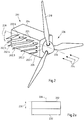
- Figure 1 shows a schematic view of an embodiment of a wind power plant 100 according to the present application with an embodiment of a nacelle 101 according to the present application.
- the wind power plant 100 is in particular an offshore wind power plant 100.
- the illustrated wind power installation 100 has a tower 120 which is arranged on a foundation 122.
- the nacelle 101 is rotatably attached to the tower 120 via a wind direction tracking device 118.
- the wind direction tracking device 118 is set up in particular to align the nacelle 101 and the rotor 106 arranged thereon, comprising a hub 108 and rotor blades 110, depending on the current wind direction for an optimal power yield.
- the wind direction tracking device 118 can comprise at least one servomotor for aligning the nacelle 101.
- the wind power plant 100 can have a measuring device (not shown) (eg wind direction transmitter) in order to measure at least the current wind direction and provide it to the wind direction tracking device 118.
- the nacelle 101 comprises a housing 104 with an outer side 105 and an inner side.
- a multiplicity of components 112, 114, 116 to be cooled can be arranged in the interior of the housing 101.
- a transmission 112, a generator 114 and a transformer 116 are arranged. Because of the heat generated during the operation of these mechanical and / or electrical components 112, 114, 116, cooling of the components 112, 114, 116 is necessary.
- a plurality of cooling fins 102 are arranged in particular on the outside 105 for cooling (only two cooling fins 102 are shown for a better overview).
- the cooling fins 102 are arranged horizontally in the present exemplary embodiment.
- the cooling fins 102 are arranged parallel to the rotor axis 126.
- a cooling fin 102 can preferably be formed from a metal and, for example, can be materially bonded (for example by a welded connection) to the outside 105 of the housing 104.
- a heat conduction is formed from the respective component 112, 114, 116 to the inside of the housing 104.
- the heat conducted to the inside can then be dissipated via the at least one cooling fin 102 arranged on the outside 105 by the air flow / wind.
- the heat conduction can be established in different ways.
- at least one gas connection (preferably air connection) is formed between the component 112, 114, 116 to be cooled and the inside of the housing 104.
- one or more breakthroughs / openings can be provided in the housing 104 of the nacelle 101 in order to direct an air flow from the component 112, 114, 116 to the inside (and back again) to be cooled allow.
- a component 112, 114, 116 to be cooled does not need to be completely enclosed.
- the air flow can be additionally supported by active means (e.g. fan).
- the arrangement of the components 112, 114, 116 in the housing 104 can be changed compared to the prior art.
- the at least one component which represents a heat source of a component 112, 114, 116 to be cooled, can be arranged in the vicinity of the inside of the housing 104.
- the inside of the housing 104 can be contacted by this component directly (or via, for example, a metallic heat conductor). In this way, particularly good heat conduction to the cooling fins 102 can be established.
- the Figure 2 schematically shows a further, particularly preferred embodiment of a gondola 201 according to the present application.
- the at least one component which is arranged in the housing 204 of the nacelle 201 and is to be cooled has not been shown. However, as described above, this can have heat conduction to the inside of the housing 204.
- a plurality of cooling fins 202.1 to 202.6 are attached to the outside 205 of the housing 204. It goes without saying that, according to other variants of the application, further cooling fins (not shown) can be arranged on a further area of the outside 205 of the housing 204. The selection of the areas of the outside on which one or more cooling fins are arranged can depend on the proximity of the components to be cooled arranged in the housing 204 and / or on further components arranged on the outside 205, such as measuring device (s).
- the arrangement of the cooling fins 202.1 to 202.6 shown schematically provides a particularly good cooling effect.
- the cooling fins 202.1 to 202.6 are at an angle of inclination compared to the (horizontal) rotor axis 226 228 inclined.
- all of the cooling fins 202.1 to 202.6 are aligned essentially parallel to one another.
- the angle of inclination 228 is preferably between 5 ° and 20 °.
- a staggered arrangement (from small to large) of the cooling fins 202.1 to 202.6 is preferably also provided.
- a first cooling fin 202.1 in particular has a lower height 230 compared to a further cooling fin 202.2 to 202.6.
- the height 230 of the cooling fin 202.2 is less than the height 230 of the cooling fins 202.3 to 202.6
- the height 230 of the cooling fin 202.3 is less than the height 230 of the cooling fins 202.4 to 202.6
- the height 230 of the cooling fin 202.4 is less than the height 230 of the Cooling fins 202.5 to 202.6
- the height 230 of the cooling fin 202.5 less than the height 230 of the cooling fin 202.6.
- FIG. 3 shows a side view of an exemplary cooling fin 202.
- the cooling fin 200 shown is formed flat. In the present case it has a planar or flat side profile. In principle, other forms are also conceivable.
- the height of the cooling fin 202 is denoted by the reference number 230 and the length of the cooling fin 202 is denoted by the reference number 232.
- the center 234 of the length 232 is denoted by the reference numeral 234.
- the height 230 of the first cooling fin 202.1 is lower in comparison to the further cooling fin 202.2.
- the distance between the rotor 206, in particular the plane spanned by the rotor blades 210, and the first cooling fin 202.1, in particular the center 234 of the length 232 of the first cooling fin 202.1 is less than the distance between the rotor 206, in particular the plane spanned by the rotor blades 210 and the further (directly adjacent) cooling rib 202.2, in particular the center 234 of the length 232 of the further cooling rib 202.2.
- a staggered arrangement can preferably be present.
- the height 230 of the cooling fins 202.1 to 202.6 can increase with increasing distance (e.g. continuously).
- the cooling fin 202.6 with the greatest distance from the rotor 206 can have the greatest height 230 and the cooling fin 202.1 with the smallest distance from the rotor 206 can have the lowest height 230, which are preferably between 20% and 50% of the maximum height 230 of the cooling fin 202.6 can.
- the air flow or wind can be used optimally for cooling the components to be cooled which are arranged in the housing.
Description
Die Erfindung betrifft eine Gondel einer Windkraftanlage, wobei die Gondel mindestens ein Gehäuse mit einer Außenseite und einer Innenseite und mindestens eine innerhalb des Gehäuses angeordnete und zu kühlende Komponente umfasst. Darüber hinaus betrifft die Erfindung eine Windkraftanlage mit der Gondel und eine Verwendung.The invention relates to a nacelle of a wind power plant, the nacelle comprising at least one housing with an outside and an inside and at least one component that is arranged inside the housing and is to be cooled. The invention also relates to a wind power plant with the nacelle and a use.
Heutzutage werden vermehrt Windenergiesysteme bzw. Windparks für die Produktion von elektrischer Energie eingesetzt. Bevorzugt werden hierbei sogenannte Offshore-Windenergiesysteme errichtet. Grund hierfür ist, dass im Vergleich zu Onshore-Windenergiesystemen die erwartete mittlere Windgeschwindigkeit und damit der zu erwartende Energieertrag aufgrund der Offshore-Lage eines derartigen Windenergiesystems in der Regel höher ist.Nowadays, wind energy systems or wind parks are increasingly used for the production of electrical energy. So-called offshore wind energy systems are preferably set up here. The reason for this is that, in comparison to onshore wind energy systems, the expected mean wind speed and thus the expected energy yield is usually higher due to the offshore location of such a wind energy system.
Ein Windenergiesystem kann eine oder mehrere Windkraftanlagen umfassen, die beispielsweise mit einer (Offshore-)Umspannstation verbunden sind. Eine Windkraftanlage umfasst im Allgemeinen einen Rotor mit einer Nabe und mit einer Mehrzahl von Rotorblättern (z.B. drei). Der Rotor ist an einer Gondel (auch Maschinengondel genannt) verbunden. Die Gondel ist in der Regel drehbar auf einem Turm befestigt.A wind energy system can comprise one or more wind turbines that are connected to an (offshore) transformer station, for example. A wind turbine generally includes a rotor with a hub and with a plurality of rotor blades (e.g. three). The rotor is connected to a nacelle (also called a machine nacelle). The gondola is usually rotatably mounted on a tower.
Die Gondel weist ein Gehäuse auf. Das Gehäuse kann mindestens eine zu kühlende Komponente, wie eine elektrische Komponente und/oder eine mechanische Komponente, umfassen. Eine elektrische Komponente ist vorliegend eine Komponente, welche mit einer elektrischen Größe betrieben wird und/oder eine elektrische Größe erzeugt.The nacelle has a housing. The housing can comprise at least one component to be cooled, such as an electrical component and / or a mechanical component. In the present case, an electrical component is a component that is operated with an electrical variable and / or generates an electrical variable.
Insbesondere kann die Gondel als elektrische Komponente mindestens einen Transformator umfassen. Dieser ist in der Regel mit einer Einhausung versehen bzw. in einem Transformatorgehäuse angeordnet, welches wiederum in dem Gehäuse der Gondel angeordnet ist. Ähnliches gilt für weitere zu kühlende Komponenten. Aufgrund der Verluste bzw. Verlustleistung muss ein derartiger Transformator gekühlt werden. In Gondeln des Standes der Technik sind komplexe Kühlungssysteme zur Kühlung der mindestens einen Komponente verbaut. Die bekannten Kühlungssysteme haben gemein, dass sie aktive Kühlungssysteme sind. Aktive Kühlungssysteme zeichnen sich dadurch aus, dass sie mit Hilfe eines Lüfters oder einer Pumpe die Wärme von der zu kühlenden Komponente abtransportieren.In particular, the nacelle can comprise at least one transformer as an electrical component. This is usually provided with a housing or arranged in a transformer housing, which in turn is arranged in the housing of the nacelle. The same applies to other components to be cooled. Due to the losses or power loss, such a transformer must be cooled. Complex cooling systems for cooling the at least one component are installed in prior art nacelles. The known cooling systems have in common that they are active cooling systems. Active cooling systems are characterized by the fact that they transport the heat away from the component to be cooled with the help of a fan or a pump.
Wie jedoch bereits beschrieben wurde, sind entsprechende Systeme komplex und wartungsintensiv. Gerade bei Offshore-Windkraftanlagen sind Wartungen oder gar Reparaturen innerhalb einer Gondel mit hohem Aufwand und entsprechenden Kosten verbunden.However, as already described, such systems are complex and require a lot of maintenance. In the case of offshore wind turbines in particular, maintenance or even repairs within a nacelle involve a lot of effort and corresponding costs.
Aus
Der Erfindung liegt daher die Aufgabe zugrunde, eine Gondel für eine Windkraftanlage zur Verfügung zu stellen, welche eine ausreichende, insbesondere verbesserte Kühlung von mindestens einer elektrischen Komponente der Gondel in einfacherer Weise ermöglicht.The invention is therefore based on the object of providing a nacelle for a wind power plant which enables sufficient, in particular improved, cooling of at least one electrical component of the nacelle in a simpler manner.
Die Aufgabe wird gemäß einem ersten Aspekt der Erfindung durch eine Gondel einer Windkraftanlage gemäß Anspruch 1 gelöst. Die Gondel umfasst mindestens ein Gehäuse mit einer Außenseite und einer Innenseite. Die Gondel umfasst mindestens eine innerhalb des Gehäuses angeordnete und zu kühlende Komponente. Die Gondel zeichnet sich dadurch aus, dass mindestens eine Kühlrippe an der Außenseite des Gehäuses angeordnet ist.According to a first aspect of the invention, the object is achieved by a nacelle of a wind power plant according to claim 1. The nacelle comprises at least one housing with an outside and an inside. The nacelle comprises at least one component that is arranged within the housing and is to be cooled. The gondola is characterized in that at least one cooling rib is arranged on the outside of the housing.
Im Gegensatz zum Stand der Technik ist bei der erfindungsgemäßen Gondel an der Außenseite mindestens eine Kühlrippe, vorzugsweise eine Mehrzahl von Kühlrippen, vorgesehen, um eine verbesserte Wärmeableitung der Wärme bereitzustellen, die durch die mindestens eine in der Gondel angeordnete und zu kühlende Komponente hervorgerufen wird. In einfacherer Weise kann eine ausreichende Kühlung zur Verfügung gestellt werden, Komplexe aktive Kühlungssysteme in der Gondel können zumindest weniger komplex gestaltet sein und insbesondere entfallen. Der Wartungs- und Reparaturaufwand und damit die entsprechenden Kosten können signifikant reduziert werden.In contrast to the prior art, the nacelle according to the invention has at least one cooling rib, preferably a plurality of cooling ribs, on the outside. provided in order to provide an improved heat dissipation of the heat which is caused by the at least one component arranged in the nacelle and to be cooled. Adequate cooling can be made available in a simpler manner; complex active cooling systems in the nacelle can be designed at least less complex and, in particular, can be omitted. The maintenance and repair effort and thus the corresponding costs can be significantly reduced.
Eine Windkraftanlage verfügt über eine Gondel, die auf dem Turm angeordnet ist. An der Gondel ist ein Rotor mit einer Nabe und Rotorblättern befestigt. Im Betrieb wird die Gondel mit dem Rotor abhängig von der augenblicklichen Windrichtung ausgerichtet. Hierzu kann eine Windrichtungsnachführungsvorrichtung vorgesehen sein.A wind turbine has a nacelle that is arranged on the tower. A rotor with a hub and rotor blades is attached to the nacelle. During operation, the nacelle with the rotor is aligned depending on the current wind direction. A wind direction tracking device can be provided for this purpose.
Die Gondel verfügt über ein Gehäuse. Das Gehäuse umfasst eine Außenseite bzw. Außenwand und eine Innenseite bzw. Innenwand. Beispielsweise ist das Gehäuse aus Metall gebildet. Im Inneren des Gehäuses ist mindestens eine Komponente, insbesondere zwei oder mehr Komponenten, angeordnet, welche aufgrund der im Betrieb der mindestens einen Komponente entstehenden Wärme gekühlt werden müssen.The nacelle has a housing. The housing comprises an outer side or outer wall and an inner side or inner wall. For example, the housing is made of metal. In the interior of the housing there is at least one component, in particular two or more components, which have to be cooled due to the heat generated during operation of the at least one component.
Zur Kühlung ist erfindungsgemäß vorgesehen, mindestens eine Kühlrippe (auch Radiatorfinne genannt) an der Außenseite des Gehäuses anzuordnen. Insbesondere ist erkannt worden, dass eine Kühlung der mindestens einen zu kühlenden Komponente im Wesentlichen nur während des Betriebs der Windkraftanlage erforderlich ist. Da während des Betriebs der Windkraftanlage davon ausgegangen werden kann, dass ein Wind bzw. eine Luftbewegung mit einer ausreichenden Windstärke vorliegt, kann dieser Luftstrom nicht nur zum Antreiben des Rotors, sondern erfindungsgemäß gleichzeitig zur Kühlung verwendet werden. Insbesondere ist erkannt worden, dass mit höherer Windstärke die durch die mindestens eine im Gehäuse implementierte Komponente erzeugte Wärme steigt und gleichzeitig die Kühlleistung steigt. Diese Erkenntnis macht sich die Erfindung zur Nutze, indem mindestens eine Kühlrippe an der Außenseite angeordnet ist.For cooling, the invention provides for at least one cooling rib (also called a radiator fin) to be arranged on the outside of the housing. In particular, it has been recognized that cooling of the at least one component to be cooled is essentially only necessary during operation of the wind power plant. Since it can be assumed during operation of the wind power plant that there is a wind or air movement with a sufficient wind strength, this air flow can be used not only to drive the rotor but, according to the invention, at the same time for cooling. In particular, it has been recognized that the higher the wind force, the higher the heat generated by the at least one component implemented in the housing and, at the same time, the higher the cooling capacity. These The invention makes use of this knowledge in that at least one cooling rib is arranged on the outside.
Eine Kühlrippe kann aus einem Metall (mit guter Wärmeleitfähigkeit) sein und beispielsweise flächig gebildet sein. Das Seitenprofil einer Kühlrippe kann plan bzw. flach sein. Eine Kühlrippe kann beispielsweise durch Schweißen, Nieten, Verschrauben, etc. an der Außenseite befestigt sein.A cooling fin can be made of a metal (with good thermal conductivity) and, for example, be formed flat. The side profile of a cooling fin can be planar or flat. A cooling fin can be attached to the outside by welding, riveting, screwing, etc., for example.
Gemäß einer ersten Ausführungsform der anmeldungsgemäßen Gondel kann die mindestens eine Kühlrippe parallel zu der Rotorachse angeordnet sein. Insbesondere können zwei oder mehr Kühlrippen parallel zu der Rotorachse angeordnet sein. Unter der Rotorachse ist vorliegend die Drehachse des an der Gondel befestigten Rotors zu verstehen. Diese Rotorachse ist eine im Wesentlichen horizontale Achse. Im Vergleich zu einer vertikalen Ausrichtung der Kühlrippen kann eine verbesserte Kühlung erreicht werden.According to a first embodiment of the nacelle according to the application, the at least one cooling rib can be arranged parallel to the rotor axis. In particular, two or more cooling fins can be arranged parallel to the rotor axis. In the present case, the rotor axis is to be understood as the axis of rotation of the rotor attached to the nacelle. This rotor axis is a substantially horizontal axis. In comparison to a vertical alignment of the cooling fins, improved cooling can be achieved.
Gemäß einer bevorzugten Ausführungsform der anmeldungsgemäßen Gondel kann die mindestens eine Kühlrippe in Bezug zu der Rotorachse um einen Neigungswinkel geneigt sein. Unter einer Neigung ist vorliegend insbesondere zu verstehen, dass eine Kühlrippe nicht parallel zur Rotorachse ausgerichtet ist, sondern mit einem Neigungswinkel zu dieser Achse. Der Neigungswinkel kann zwischen 2° und 85°, insbesondere zwischen 5° und 65°, insbesondere bevorzugt zwischen 5° und 20° liegen. Tests haben gezeigt, dass eine nicht parallele Ausrichtung zur Rotorachse, sondern mit einem Neigungswinkel insbesondere bevorzugt zwischen 5° und 20° zwischen eine höhere Kühlleistung - im Vergleich zu einer horizontalen Ausrichtung der Kühlrippen - erreicht werden kann.According to a preferred embodiment of the nacelle according to the application, the at least one cooling rib can be inclined at an angle of inclination in relation to the rotor axis. In the present case, an inclination is to be understood in particular to mean that a cooling fin is not aligned parallel to the rotor axis, but rather at an angle of inclination to this axis. The angle of inclination can be between 2 ° and 85 °, in particular between 5 ° and 65 °, particularly preferably between 5 ° and 20 °. Tests have shown that an alignment that is not parallel to the rotor axis, but with an angle of inclination between 5 ° and 20 ° between a higher cooling capacity - compared to a horizontal alignment of the cooling fins - can be achieved.
Vorzugsweise können eine Mehrzahl von Kühlrippen im Wesentlichen parallel zueinander angeordnet sein. Mit anderen Worten können diese Kühlrippen den gleichen Neigungswinkel aufweisen. Der Abstand zwischen zwei Kühlrippen kann bevorzugt zwischen 1 bis 10 cm. Liegen. Eine derartige Ausbildung bietet eine gute Kühlleistung.A plurality of cooling fins can preferably be arranged essentially parallel to one another. In other words, these cooling fins can have the same angle of inclination. The distance between two cooling fins can preferably between 1 to 10 cm. Lie. Such a design offers good cooling performance.
Es sei angemerkt, dass bei einer Ausführungsform, bei der eine Kühlrippe einen gebogenen Verlauf aufweist, der Neigungswinkel insbesondere der Winkel zwischen der Rotorachse und der über die Länge der Kühlrippe gemittelten Neigung (oder Steigung) ist.It should be noted that in an embodiment in which a cooling fin has a curved profile, the angle of inclination is in particular the angle between the rotor axis and the inclination (or pitch) averaged over the length of the cooling fin.
Um eine besonders hohe Kühlleistung zu erzielen, kann in einer besonders bevorzugten Ausführungsform eine Mehrzahl von geneigt angeordneten Kühlrippen der Höhe nach (von klein nach groß) aus Sicht des Rotors gestaffelt angeordnet sein. Gemäß der Ausführungsform können mindestens zwei Kühlrippen an der Außenseite des Gehäuses angeordnet sein. Die erste Kühlrippe (der zumindest zwei Kühlrippen) kann im Vergleich zu der mindestens einen weiteren Kühlrippe (der zumindest zwei Kühlrippen) einen geringeren Abstand zu einem an der Gondel angeordneten Rotor aufweisen. Die Höhe der ersten Kühlrippe kann zumindest geringer als die Höhe der mindestens einen weiteren Kühlrippe sein. Beispielsweise kann die weitere Kühlrippe zumindest um 5%, vorzugsweise 8%, höher als die erste Kühlrippe gebildet sein. Dies ermöglicht eine noch bessere Kühlleistung durch den Wind. Vorzugsweise können sämtliche angeordnete Kühlrippen unterschiedliche Höhen aufweisen. Die jeweils einer Kühlrippe nachgelagerte Kühlrippe (von dem Rotor ausgesehen) kann eine größere Höhe aufweisen.In order to achieve a particularly high cooling performance, in a particularly preferred embodiment a plurality of inclined cooling fins can be staggered in height (from small to large) from the perspective of the rotor. According to the embodiment, at least two cooling fins can be arranged on the outside of the housing. The first cooling fin (of the at least two cooling fins) can have a smaller distance from a rotor arranged on the nacelle in comparison to the at least one further cooling fin (of the at least two cooling fins). The height of the first cooling fin can be at least less than the height of the at least one further cooling fin. For example, the further cooling fin can be formed at least 5%, preferably 8%, higher than the first cooling fin. This enables an even better cooling performance by the wind. Preferably, all of the arranged cooling fins can have different heights. The cooling fin located downstream of a cooling fin (as seen from the rotor) can have a greater height.
Darüber hinaus kann die mindestens eine zu kühlende Komponente mindestens eine mechanische Komponente sein. Insbesondere kann die mechanische Komponente ein Getriebe sein. Alternativ oder zusätzlich kann die mindestens eine zu kühlende Komponente eine elektrische Komponente sein. Beispielhafte elektrische Komponenten sind Transformatoren oder Generatoren. Beispielsweise kann ein Generator über ein Getriebe mit dem Rotor verbunden sein, um die kinetische Energie des Windes in elektrische Energie bzw. Leistung zu wandeln. Der in dem Gehäuse vorgesehene Transformator kann eingesetzt werden, um die produzierte Leistung auf ein vorbestimmtes Spannungsniveau zu transformieren. Entsprechende Komponente müssen während ihres Betriebs gekühlt werden. Es versteht sich, dass weitere zu kühlende und/oder nicht zu kühlende Komponenten in dem Gehäuse der Gondel integriert sein können.In addition, the at least one component to be cooled can be at least one mechanical component. In particular, the mechanical component can be a transmission. Alternatively or additionally, the at least one component to be cooled can be an electrical component. Exemplary electrical components are transformers or generators. For example, a generator can be connected to the rotor via a gearbox in order to convert the kinetic energy of the wind into electrical energy or power. The transformer provided in the housing can be used to increase the power produced to transform a predetermined voltage level. Corresponding components must be cooled during their operation. It goes without saying that further components to be cooled and / or not to be cooled can be integrated in the housing of the nacelle.
Um eine gute Wärmeableitung von der zu kühlenden Komponente über die mindestens eine Kühlrippe zu ermöglichen, kann gemäß einer weiteren Ausführungsform der anmeldungsgemäßen Gondel zwischen einer Innenseite des Gehäuses und der mindestens einen zu kühlenden Komponente eine Wärmeleitung gebildet sein. Insbesondere kann zwischen dem mindestens einen Bauteil der zu kühlenden Komponente, welches die (Haupt-)Wärmequelle bildet, und der Innenseite des Gehäuses eine Wärmeleitung gebildet sein. Von der Innenseite des Gehäuses kann dann die erzeugte Wärme über die Außenseite und die daran angeordnete mindestens eine Kühlrippe durch den Wind abgeleitet werden.In order to enable good heat dissipation from the component to be cooled via the at least one cooling rib, according to a further embodiment of the gondola according to the application, a heat conduction can be formed between an inside of the housing and the at least one component to be cooled. In particular, a heat conduction can be formed between the at least one component of the component to be cooled, which forms the (main) heat source, and the inside of the housing. The heat generated can then be dissipated by the wind from the inside of the housing via the outside and the at least one cooling fin arranged thereon.
Bei einer besonders bevorzugten Ausführungsform kann vorgesehen sein, dass die Wärmeleitung durch eine Gasverbindung gebildet ist. Insbesondere kann die zu kühlende Komponente in dem Gehäuse derart angeordnet sein, dass eine Luftverbindung zwischen der Innenseite und der zu kühlenden Komponente existiert. Beispielsweise kann innerhalb des Gehäuses mindestens ein Durchbruch vorgesehen sein, der einen Luftfluss zwischen der zu kühlende Komponente und der Innenseite ermöglicht. Vorzugsweise können mehrere Durchbrüche vorgesehen sein, um einen zirkulierten Kühlluftfluss bereitzustellen. Mit anderen Worten kann die erwärmte Luft in Richtung der Innenseite über einen ersten Luftkanal gelenkt und die abgekühlte Luft über mindestens einen weiteren Luftkanal (zurück) zur zu kühlenden Komponente gelenkt werden. Um den Luftfluss zu bewirken, kann gemäß einer Ausführungsform ein Ventilator vorgesehen sein.In a particularly preferred embodiment it can be provided that the heat conduction is formed by a gas connection. In particular, the component to be cooled can be arranged in the housing in such a way that an air connection exists between the inside and the component to be cooled. For example, at least one opening can be provided within the housing, which allows air to flow between the component to be cooled and the inside. A plurality of openings can preferably be provided in order to provide a circulated flow of cooling air. In other words, the heated air can be directed in the direction of the inside via a first air duct and the cooled air can be directed (back) to the component to be cooled via at least one further air duct. In order to bring about the air flow, a fan can be provided according to one embodiment.
Darüber hinaus kann vorgesehen sein, dass eine zu kühlende Komponente zumindest nicht vollständig eingehaust ist. Beispielsweise kann ein Transformator ohne eine Einhausung in dem Gehäuse angeordnet sein.In addition, it can be provided that a component to be cooled is at least not completely enclosed. For example, a transformer can be arranged in the housing without a housing.
Alternativ oder zusätzlich kann bei einer weiteren Ausführungsform vorgesehen sein, dass eine zu kühlende Komponente die Innenseite des Gehäuses der Gondel zumindest teilweise direkt (oder über eine Wärmeverbindung z.B. in Form einer Metallverbindung) kontaktiert. Durch eine entsprechende Anordnung einer zu kühlenden Komponente kann die entstehende Wärme besonders gut über die mindestens eine Kühlrippe abgeführt werden.Alternatively or additionally, in a further embodiment it can be provided that a component to be cooled makes contact with the inside of the housing of the nacelle at least partially directly (or via a thermal connection, e.g. in the form of a metal connection). With a corresponding arrangement of a component to be cooled, the resulting heat can be dissipated particularly well via the at least one cooling fin.
Ein weiterer Aspekt der Erfindung ist eine Windkraftanlage umfassend eine zuvor beschriebene Gondel. Die Windkraftanlage kann Bestandteil eines Windenergiesystems bzw. Windparks sein. Vorzugsweise kann die Windkraftanlage eine Offshore-Windkraftanlage sein. Alternativ kann es sich bei der Windkraftanlage auch um eine Onshore-Windkraftanlage handeln.Another aspect of the invention is a wind power plant comprising a nacelle as described above. The wind turbine can be part of a wind energy system or wind park. The wind turbine can preferably be an offshore wind turbine. Alternatively, the wind turbine can also be an onshore wind turbine.
Ein noch weiterer Aspekt der Erfindung ist eine Verwendung gemäß Anspruch 12. Die erfindungsgemäße Verwendung ermöglicht eine verbesserte Kühlung und/oder einen (Teil-)Verzicht auf aktive und komplexe Kühlungssysteme innerhalb des Gehäuses der Gondel.Yet another aspect of the invention is a use according to claim 12. The use according to the invention enables improved cooling and / or a (partial) waiver of active and complex cooling systems within the housing of the nacelle.
Es gibt nun eine Vielzahl von Möglichkeiten, die erfindungsgemäße Windkraftanlage, die erfindungsgemäße Gondel und die Verwendung auszugestalten und weiterzuentwickeln. Hierzu sei einerseits verwiesen auf die den unabhängigen Patentansprüchen nachgeordneten Patentansprüche, andererseits auf die Beschreibung von Ausführungsbeispielen in Verbindung mit der Zeichnung. In der Zeichnung zeigt:
- Fig. 1
- eine schematische Ansicht eines Ausführungsbeispiels einer Windkraftanlage gemäß der vorliegenden Anmeldung,
- Fig. 2
- eine schematische Ansicht eines Ausführungsbeispiels einer Gondel gemäß der vorliegenden Anmeldung, und
- Fig. 2a
- eine schematische Ansicht eines Ausführungsbeispiel einer Kühlrippe gemäß der vorliegenden Anmeldung.
- Fig. 1
- a schematic view of an embodiment of a wind turbine according to the present application,
- Fig. 2
- a schematic view of an embodiment of a gondola according to the present application, and
- Fig. 2a
- a schematic view of an embodiment of a cooling fin according to the present application.
In den Figuren werden für gleiche Elemente gleiche Bezugszeichen verwendet.In the figures, the same reference symbols are used for the same elements.
Die dargestellte Windkraftanlage 100 verfügt über einen Turm 120, der auf einem Fundament 122 angeordnet ist. Die Gondel 101 ist vorliegend über eine Windrichtungsnachführungsvorrichtung 118 drehbar an dem Turm 120 befestigt. Die Windrichtungsnachführungsvorrichtung 118 ist insbesondere eingerichtet, die Gondel 101 und den daran angeordneten Rotor 106 umfassend eine Nabe 108 und Rotorblätter 110 abhängig von der aktuellen Windrichtung für einen optimalen Stromertrag auszurichten. Die Windrichtungsnachführungsvorrichtung 118 kann zum Ausrichten der Gondel 101 mindestens einen Stellmotor umfassen. Beispielsweise kann die Windkraftanlage 100 über eine (nicht gezeigte) Messeinrichtung (z.B. Windrichtungsgeber) verfügen, um zumindest die augenblickliche Windrichtung zu messen und der Windrichtungsnachführungsvorrichtung 118 bereitzustellen.The illustrated
Die Gondel 101 umfasst ein Gehäuse 104 mit einer Außenseite 105 und einer Innenseite. Im Inneren des Gehäuses 101 kann eine Vielzahl von zu kühlenden Komponenten 112, 114, 116 angeordnet sein. Vorliegend sind ein Getriebe 112, ein Generator 114 und ein Transformator 116 angeordnet. Aufgrund der im Betrieb dieser mechanischen und/oder elektrischen Komponenten 112, 114, 116 entstehenden Wärme ist eine Kühlung der Komponenten 112, 114, 116 erforderlich.The nacelle 101 comprises a
Es versteht sich, dass gemäß anderen Varianten andere und/oder weitere zu kühlende Komponenten vorgesehen sein können. Es versteht sich ferner, dass auch nicht zu kühlende Komponenten in der Gondel 101 angeordnet sein können.It goes without saying that, according to other variants, other and / or further components to be cooled can be provided. It is also understood that components that are not to be cooled can also be arranged in the nacelle 101.
Vorliegend ist zur Kühlung an der Außenseite 105 insbesondere eine Mehrzahl von Kühlrippen 102 angeordnet (zur besseren Übersicht sind lediglich zwei Kühlrippen 102 dargestellt). Wie aus der
Um die durch eine der Komponenten 112, 114, 116 erzeugte Wärme abzuführen, ist insbesondere eine Wärmleitung von der jeweiligen Komponente 112,114, 116 zur Innenseite des Gehäuses 104 gebildet. Dann kann die an die Innenseite geleitete Wärme über die an der Außenseite 105 angeordnete mindestens eine Kühlrippe 102 durch die/den Luftströmung/Wind abgeführt werden.In order to dissipate the heat generated by one of the
Die Wärmeleitung kann auf unterschiedliche Weise hergestellt werden. Bei einer Ausführungsform ist zwischen der zu kühlenden Komponente 112, 114, 116 und der Innenseite des Gehäuses 104 mindestens eine Gasverbindung (vorzugsweise Luftverbindung) gebildet. Insbesondere können in dem Gehäuse 104 der Gondel 101 ein oder mehrere Durchbruch/brüche vorgesehen sein, um einen Luftfluss von der zu kühlenden Komponente 112,114, 116 zur Innenseite (und wieder zurück) zu erlauben. Insbesondere kann auf eine vollständige Einhausung einer zu kühlenden Komponente 112,114,116 verzichtet werden. Es versteht sich, dass der Luftfluss durch aktive Mittel (z.B. Ventilator) zusätzlich unterstützt werden kann.The heat conduction can be established in different ways. In one embodiment, at least one gas connection (preferably air connection) is formed between the
Darüber hinaus kann die Anordnung der Komponenten 112, 114, 116 in dem Gehäuse 104 im Vergleich zum Stand der Technik geändert sein. Insbesondere kann das mindestens eine Bauteil, welches eine Wärmequelle einer zu kühlenden Komponente 112, 114, 116 darstellt, in der Nähe der Innenseite des Gehäuses 104 angeordnet sein. Besonders bevorzugt kann die Innenseite des Gehäuses 104 von diesem Bauteil direkt (oder über z.B. eine metallischen Wärmeleiter) kontaktiert werden. Hierdurch kann eine besonders gute Wärmeleitung zu den Kühlrippen 102 hergestellt werden.In addition, the arrangement of the
Die
An der Außenseite 205 des Gehäuses 204 ist eine Mehrzahl von Kühlrippen 202.1 bis 202.6 befestigt. Es versteht sich, dass gemäß anderen Varianten der Anmeldung an weiteren Bereich der Außenseite 205 des Gehäuses 204 weitere (nicht gezeigte) Kühlrippen angeordnet sein können. Die Wahl der Bereiche der Außenseite, an denen eine oder mehrere Kühlrippen angeordnet sind, kann von der Nähe der in dem Gehäuse 204 angeordneten, zu kühlenden Komponenten und/oder von an der Außenseite 205 angeordneten weiteren Bauteilen, wie Messeinrichtung(en), abhängen.A plurality of cooling fins 202.1 to 202.6 are attached to the outside 205 of the
Die schematisch dargestellte Anordnung der Kühlrippen 202.1 bis 202.6 stellt eine besonders gute Kühlwirkung zur Verfügung. So sind vorliegend die Kühlrippen 202.1 bis 202.6 im Vergleich zur (horizontalen) Rotorachse 226 um einen Neigungswinkel 228 geneigt. Vorliegend sind sämtliche Kühlrippen 202.1 bis 202.6 im Wesentlichen parallel zueinander ausgerichtet. Der Neigungswinkel 228 liegt vorzugsweise zwischen 5° und 20°. Durch die Neigung wird ein Luftstrom (insbesondere Wind) 224 mit einer längeren Verweilzeit an den Kühlrippen 202.1 bis 202.6 vorbeigeführt. Eine verbesserte Kühlwirkung kann erreicht werden.The arrangement of the cooling fins 202.1 to 202.6 shown schematically provides a particularly good cooling effect. In the present case, the cooling fins 202.1 to 202.6 are at an angle of inclination compared to the (horizontal)
Es versteht sich, dass bei anderen Varianten nicht sämtliche mit dem gleichen Neigungswinkel geneigt sein müssen.It goes without saying that with other variants not all of them have to be inclined at the same angle of inclination.
Neben dem Vorsehen einer Neigung in Bezug zur Rotorachse 226 ist vorzugsweise zusätzlich eine gestaffelte Anordnung (von klein zu groß) der Kühlrippen 202.1 bis 202.6 vorgesehen. Wie der
Wie oben beschrieben wurde, ist vorliegend die Höhe 230 der ersten Kühlrippe 202.1 im Vergleich zu der weiteren Kühlrippe 202.2 geringer. Hierbei ist der Abstand zwischen dem Rotor 206, insbesondere der durch die Rotorblätter 210 aufgespannten Ebene, und der ersten Kühlrippe 202.1, insbesondere der Mitte 234 der Länge 232 der ersten Kühlrippe 202.1, geringer als der Abstand zwischen dem Rotor 206, insbesondere der durch die Rotorblätter 210 aufgespannten Ebene, und der weiteren (direkt benachbarten) Kühlrippe 202.2, insbesondere der Mitte 234 der Länge 232 der weiteren Kühlrippe 202.2.As has been described above, the
Vorzugsweise kann eine gestaffelte Anordnung vorliegen. Insbesondere kann die Höhe 230 der Kühlrippen 202.1 bis 202.6 mit größer werdendem Abstand (z.B. kontinuierlich) ansteigen. Vorzugsweise kann die Kühlrippe 202.6 mit dem größten Abstand zum Rotor 206 die größte Höhe 230 aufweisen und die Kühlrippe 202.1 mit dem geringsten Abstand zum Rotor 206 die niedrigste Höhe 230 aufweisen, die vorzugsweise zwischen 20 % und 50 % der maximalen Höhe 230 der Kühlrippe 202.6 liegen kann.A staggered arrangement can preferably be present. In particular, the
Indem eine nach der Höhe 230 vorgenommene Staffelung und die beschriebene Neigung der Kühlrippen202.1 bis 202.6 vorgesehen ist, kann der Luftstrom bzw. Wind optimal zur Kühlung der im Gehäuse angeordneten, zu kühlenden Komponenten verwendet werden.By providing a graduation made according to the
Claims (12)
- Nacelle (101, 201) of a wind turbine (100), comprising:- at least one housing (104, 204) with an outer side (105, 205) and an inner side, and- at least one component (112, 114, 116) located within the housing (104, 204) and to be cooled,- wherein at least two cooling fins (102, 202, 202.1, 202.2, 202.3, 202.4, 202.5, 202.6) are arranged on the outer side (105, 205) of the housing (104, 204),- wherein at least two cooling fins (102, 202, 202.1, 202.2, 202.3, 202.4, 202.5, 202.6) are arranged parallel to the rotor axis (126, 226) or at least one cooling fin (102, 202, 202.1, 202.2, 202.3, 202.4, 202.5, 202.6) is inclined relative to the rotor axis (126, 226) by an angle of inclination (228), wherein the angle of inclination (228) is between 2° and 85°,
characterized in that- a first cooling fin (102, 202, 202.1, 202.2, 202.3, 202.4, 202.5, 202.6) has a smaller distance from a rotor (106, 206) arranged on the nacelle (101, 201) compared to the at least one further cooling fin (102, 202, 202.1, 202.2, 202.3, 202.4, 202.5, 202.6), and- the height (230) of the first cooling fin (102, 202, 202.1, 202.2, 202.3, 202.4, 202.5, 202.6) is at least less than the height (230) of the at least one further cooling fin (102, 202, 202.1, 202.2, 202.3, 202.4, 202.5, 202.6), - Nacelle (101, 201) according to claim 1, characterized in that the angle of inclination (228) is between 5° and 65°.
- Nacelle (101, 201) according to claim 2, characterized in that the angle of inclination is between 5° and 20°.
- Nacelle (101, 201) according to claim 1, 2 or 3, characterized in that a plurality of cooling fins (102, 202, 202.1, 202.2, 202.3, 202.4, 202.5, 202.6) are inclined with respect to the rotor axis (126, 226) by the same angle of inclination (228).
- Nacelle (101, 201) according to one of the previous claims, characterized in that- the at least one component (112, 114, 116) to be cooled is at least one mechanical component (112),
and/or- the at least one component (112, 114, 116) to be cooled is at least one electrical component (114, 116). - Nacelle (101, 201) according to claim 5, characterized in that the mechanical component (112) is a gear (112).
- Nacelle (101, 201) according to claim 5, characterized in that the electrical component (114, 116) is a transformer (116) or a generator (114).
- Nacelle (101, 201) according to one of the previous claims, characterized in that a heat conduction is formed between an inner side of the housing (104, 204) and the at least one component (112, 114, 116) to be cooled.
- Nacelle (101, 201) according to claim 8, characterized in that the heat conduction is formed by a gas connection.
- Wind turbine (100) comprising a nacelle (101, 201) according to one of the previous claims.
- Wind turbine (100) according to claim 10, characterized in that the wind turbine (100) is an offshore wind turbine (100).
- Use of at least two cooling fins (102, 202.2, 202.3, 202.4, 202.5, 202.6) arranged on an outer side (105, 205) of a housing of a nacelle (101, 201) of a wind turbine (100) for cooling at least one component (112, 114, 116) located within the housing (104, 204) and to be cooled, wherein a first cooling fin (102, 202.2, 202.3, 202.4, 202.5, 202.6) has a smaller distance to a rotor (106, 206) arranged on the nacelle (101, 201) in comparison with the at least one further cooling fin (102, 202, 202.1, 202.2, 202.3, 202.4, 202.5, 202.6), wherein the height (230) of the first cooling fin (102, 202, 202.1, 202.2, 202.3, 202.4, 202.5, 202.6) is at least less than the height (230) of the at least one further cooling fin (102, 202, 202.1, 202.2, 202.3, 202.4, 202.5, 202.6), wherein at least two cooling fins (102, 202, 202.1, 202.2, 202.3, 202.4, 202.5, 202.6) are arranged parallel to the rotor axis (126, 226) or at least one cooling fin (102, 202, 202.1, 202.2, 202.3, 202.4, 202.5, 202.6) is inclined with respect to the rotor axis (126, 226) by an angle of inclination (228), wherein the angle of inclination (228) is between 2° and 85°.
Priority Applications (1)
| Application Number | Priority Date | Filing Date | Title |
|---|---|---|---|
| PL18700128T PL3571402T3 (en) | 2017-01-23 | 2018-01-09 | Nacelle of a wind power plant |
Applications Claiming Priority (2)
| Application Number | Priority Date | Filing Date | Title |
|---|---|---|---|
| DE102017101207.9A DE102017101207A1 (en) | 2017-01-23 | 2017-01-23 | GONDEL OF A WIND POWER PLANT |
| PCT/EP2018/050452 WO2018134083A1 (en) | 2017-01-23 | 2018-01-09 | Nacelle of a wind power plant |
Publications (2)
| Publication Number | Publication Date |
|---|---|
| EP3571402A1 EP3571402A1 (en) | 2019-11-27 |
| EP3571402B1 true EP3571402B1 (en) | 2021-03-03 |
Family
ID=60937784
Family Applications (1)
| Application Number | Title | Priority Date | Filing Date |
|---|---|---|---|
| EP18700128.4A Active EP3571402B1 (en) | 2017-01-23 | 2018-01-09 | Nacelle of a wind power plant |
Country Status (5)
| Country | Link |
|---|---|
| EP (1) | EP3571402B1 (en) |
| DE (1) | DE102017101207A1 (en) |
| ES (1) | ES2863455T3 (en) |
| PL (1) | PL3571402T3 (en) |
| WO (1) | WO2018134083A1 (en) |
Family Cites Families (8)
| Publication number | Priority date | Publication date | Assignee | Title |
|---|---|---|---|---|
| DE10124268B4 (en) * | 2001-05-18 | 2006-02-09 | Wobben, Aloys, Dipl.-Ing. | generator cooling |
| DE10351844A1 (en) * | 2003-11-06 | 2005-06-09 | Alstom | Wind power plant for producing electricity has electrical components connected to radiator projecting through cutout in shell of gondola |
| US7345376B2 (en) * | 2004-11-30 | 2008-03-18 | Distributed Energy Systems Corporation | Passively cooled direct drive wind turbine |
| EP2453131A3 (en) * | 2006-12-22 | 2012-07-25 | Wilic S.ar.l. | Multiple generator wind turbine |
| ITMI20081122A1 (en) * | 2008-06-19 | 2009-12-20 | Rolic Invest Sarl | WIND GENERATOR PROVIDED WITH A COOLING SYSTEM |
| US8403638B2 (en) * | 2010-06-30 | 2013-03-26 | Mitsubishi Heavy Industries, Ltd. | Wind power generator |
| BR112014017330A2 (en) * | 2012-01-13 | 2017-06-13 | Youwinenergy | cooling system for a wind turbine |
| KR101434443B1 (en) * | 2012-12-27 | 2014-08-28 | 삼성중공업 주식회사 | Apparatus for nacelle air cooling using by heat exchanger |
-
2017
- 2017-01-23 DE DE102017101207.9A patent/DE102017101207A1/en not_active Withdrawn
-
2018
- 2018-01-09 WO PCT/EP2018/050452 patent/WO2018134083A1/en active Application Filing
- 2018-01-09 PL PL18700128T patent/PL3571402T3/en unknown
- 2018-01-09 EP EP18700128.4A patent/EP3571402B1/en active Active
- 2018-01-09 ES ES18700128T patent/ES2863455T3/en active Active
Non-Patent Citations (1)
| Title |
|---|
| None * |
Also Published As
| Publication number | Publication date |
|---|---|
| DE102017101207A1 (en) | 2018-07-26 |
| EP3571402A1 (en) | 2019-11-27 |
| WO2018134083A1 (en) | 2018-07-26 |
| PL3571402T3 (en) | 2021-09-13 |
| ES2863455T3 (en) | 2021-10-11 |
Similar Documents
| Publication | Publication Date | Title |
|---|---|---|
| EP1200733B2 (en) | Wind energy facility with a closed cooling circuit | |
| DE19932394C2 (en) | Wind turbine with a closed cooling circuit | |
| DE10000370A1 (en) | Wind power plant with completely closed or at least partly closed cooling circuit with which heat to be abstracted from cooling circuit is transmitted to wind power plant across tower or nacelle | |
| EP1038103A1 (en) | Wind power plat and method for cooling a generator in a wind power plant | |
| WO2002095222A1 (en) | Cooling device for a wind turbine generator | |
| DE102011055012A1 (en) | Noise reducer for a rotor blade in wind turbines | |
| EP3397859B1 (en) | Wind turbine and cooling device for a wind turbine | |
| EP1756842A2 (en) | System for cooling components of wind power stations | |
| EP2990644A1 (en) | Wind power assembly | |
| EP3472462B1 (en) | Modular wind turbine | |
| EP3571402B1 (en) | Nacelle of a wind power plant | |
| EP3308449B1 (en) | Stator ring for an electric generator, and generator and wind turbine having said stator ring | |
| EP3317533B1 (en) | Wind turbine and cooling device for a wind turbine | |
| WO2020064421A1 (en) | Driving device for a ship and method for operation thereof | |
| EP4015818A1 (en) | Wind energy system | |
| EP3560051B1 (en) | Substation, method and device for a substation | |
| WO2016203035A1 (en) | Wind turbine tower and wind turbine | |
| DE102018202691A1 (en) | Power generator arrangement with cooling system | |
| DE112014000368T5 (en) | Wind Turbine Generator System | |
| EP3344871A1 (en) | Wind energy installation and method for controlling a cooling of a wind energy installation | |
| EP4067650A1 (en) | Air cooling device, generator, air guiding device, wind turbine and method for manufacturing a generator and a wind turbine | |
| DE102013205966A1 (en) | Stator for an electric machine | |
| DE102012102876A1 (en) | Wind turbine with two rotors | |
| DE102019208619A1 (en) | Heat exchanger, method for producing a heat exchanger and power plant with such a heat exchanger | |
| EP4073377A1 (en) | Generator and method for disassembling a generator of a directly driven wind turbine |
Legal Events
| Date | Code | Title | Description |
|---|---|---|---|
| STAA | Information on the status of an ep patent application or granted ep patent |
Free format text: STATUS: UNKNOWN |
|
| STAA | Information on the status of an ep patent application or granted ep patent |
Free format text: STATUS: THE INTERNATIONAL PUBLICATION HAS BEEN MADE |
|
| PUAI | Public reference made under article 153(3) epc to a published international application that has entered the european phase |
Free format text: ORIGINAL CODE: 0009012 |
|
| STAA | Information on the status of an ep patent application or granted ep patent |
Free format text: STATUS: REQUEST FOR EXAMINATION WAS MADE |
|
| 17P | Request for examination filed |
Effective date: 20190517 |
|
| AK | Designated contracting states |
Kind code of ref document: A1 Designated state(s): AL AT BE BG CH CY CZ DE DK EE ES FI FR GB GR HR HU IE IS IT LI LT LU LV MC MK MT NL NO PL PT RO RS SE SI SK SM TR |
|
| GRAP | Despatch of communication of intention to grant a patent |
Free format text: ORIGINAL CODE: EPIDOSNIGR1 |
|
| STAA | Information on the status of an ep patent application or granted ep patent |
Free format text: STATUS: GRANT OF PATENT IS INTENDED |
|
| INTG | Intention to grant announced |
Effective date: 20200804 |
|
| RAP1 | Party data changed (applicant data changed or rights of an application transferred) |
Owner name: RWE RENEWABLES GMBH |
|
| GRAS | Grant fee paid |
Free format text: ORIGINAL CODE: EPIDOSNIGR3 |
|
| STAA | Information on the status of an ep patent application or granted ep patent |
Free format text: STATUS: GRANT OF PATENT IS INTENDED |
|
| GRAA | (expected) grant |
Free format text: ORIGINAL CODE: 0009210 |
|
| STAA | Information on the status of an ep patent application or granted ep patent |
Free format text: STATUS: THE PATENT HAS BEEN GRANTED |
|
| AK | Designated contracting states |
Kind code of ref document: B1 Designated state(s): AL AT BE BG CH CY CZ DE DK EE ES FI FR GB GR HR HU IE IS IT LI LT LU LV MC MK MT NL NO PL PT RO RS SE SI SK SM TR |
|
| REG | Reference to a national code |
Ref country code: GB Ref legal event code: FG4D Free format text: NOT ENGLISH |
|
| REG | Reference to a national code |
Ref country code: AT Ref legal event code: REF Ref document number: 1367477 Country of ref document: AT Kind code of ref document: T Effective date: 20210315 Ref country code: CH Ref legal event code: EP |
|
| REG | Reference to a national code |
Ref country code: DE Ref legal event code: R096 Ref document number: 502018004125 Country of ref document: DE |
|
| REG | Reference to a national code |
Ref country code: IE Ref legal event code: FG4D Free format text: LANGUAGE OF EP DOCUMENT: GERMAN |
|
| REG | Reference to a national code |
Ref country code: LT Ref legal event code: MG9D |
|
| PG25 | Lapsed in a contracting state [announced via postgrant information from national office to epo] |
Ref country code: NO Free format text: LAPSE BECAUSE OF FAILURE TO SUBMIT A TRANSLATION OF THE DESCRIPTION OR TO PAY THE FEE WITHIN THE PRESCRIBED TIME-LIMIT Effective date: 20210603 Ref country code: LT Free format text: LAPSE BECAUSE OF FAILURE TO SUBMIT A TRANSLATION OF THE DESCRIPTION OR TO PAY THE FEE WITHIN THE PRESCRIBED TIME-LIMIT Effective date: 20210303 Ref country code: HR Free format text: LAPSE BECAUSE OF FAILURE TO SUBMIT A TRANSLATION OF THE DESCRIPTION OR TO PAY THE FEE WITHIN THE PRESCRIBED TIME-LIMIT Effective date: 20210303 Ref country code: FI Free format text: LAPSE BECAUSE OF FAILURE TO SUBMIT A TRANSLATION OF THE DESCRIPTION OR TO PAY THE FEE WITHIN THE PRESCRIBED TIME-LIMIT Effective date: 20210303 Ref country code: GR Free format text: LAPSE BECAUSE OF FAILURE TO SUBMIT A TRANSLATION OF THE DESCRIPTION OR TO PAY THE FEE WITHIN THE PRESCRIBED TIME-LIMIT Effective date: 20210604 Ref country code: BG Free format text: LAPSE BECAUSE OF FAILURE TO SUBMIT A TRANSLATION OF THE DESCRIPTION OR TO PAY THE FEE WITHIN THE PRESCRIBED TIME-LIMIT Effective date: 20210603 |
|
| REG | Reference to a national code |
Ref country code: NL Ref legal event code: MP Effective date: 20210303 |
|
| PG25 | Lapsed in a contracting state [announced via postgrant information from national office to epo] |
Ref country code: SE Free format text: LAPSE BECAUSE OF FAILURE TO SUBMIT A TRANSLATION OF THE DESCRIPTION OR TO PAY THE FEE WITHIN THE PRESCRIBED TIME-LIMIT Effective date: 20210303 Ref country code: LV Free format text: LAPSE BECAUSE OF FAILURE TO SUBMIT A TRANSLATION OF THE DESCRIPTION OR TO PAY THE FEE WITHIN THE PRESCRIBED TIME-LIMIT Effective date: 20210303 Ref country code: RS Free format text: LAPSE BECAUSE OF FAILURE TO SUBMIT A TRANSLATION OF THE DESCRIPTION OR TO PAY THE FEE WITHIN THE PRESCRIBED TIME-LIMIT Effective date: 20210303 |
|
| PG25 | Lapsed in a contracting state [announced via postgrant information from national office to epo] |
Ref country code: NL Free format text: LAPSE BECAUSE OF FAILURE TO SUBMIT A TRANSLATION OF THE DESCRIPTION OR TO PAY THE FEE WITHIN THE PRESCRIBED TIME-LIMIT Effective date: 20210303 |
|
| REG | Reference to a national code |
Ref country code: ES Ref legal event code: FG2A Ref document number: 2863455 Country of ref document: ES Kind code of ref document: T3 Effective date: 20211011 |
|
| PG25 | Lapsed in a contracting state [announced via postgrant information from national office to epo] |
Ref country code: EE Free format text: LAPSE BECAUSE OF FAILURE TO SUBMIT A TRANSLATION OF THE DESCRIPTION OR TO PAY THE FEE WITHIN THE PRESCRIBED TIME-LIMIT Effective date: 20210303 Ref country code: CZ Free format text: LAPSE BECAUSE OF FAILURE TO SUBMIT A TRANSLATION OF THE DESCRIPTION OR TO PAY THE FEE WITHIN THE PRESCRIBED TIME-LIMIT Effective date: 20210303 Ref country code: SM Free format text: LAPSE BECAUSE OF FAILURE TO SUBMIT A TRANSLATION OF THE DESCRIPTION OR TO PAY THE FEE WITHIN THE PRESCRIBED TIME-LIMIT Effective date: 20210303 |
|
| PG25 | Lapsed in a contracting state [announced via postgrant information from national office to epo] |
Ref country code: IS Free format text: LAPSE BECAUSE OF FAILURE TO SUBMIT A TRANSLATION OF THE DESCRIPTION OR TO PAY THE FEE WITHIN THE PRESCRIBED TIME-LIMIT Effective date: 20210703 Ref country code: PT Free format text: LAPSE BECAUSE OF FAILURE TO SUBMIT A TRANSLATION OF THE DESCRIPTION OR TO PAY THE FEE WITHIN THE PRESCRIBED TIME-LIMIT Effective date: 20210705 Ref country code: SK Free format text: LAPSE BECAUSE OF FAILURE TO SUBMIT A TRANSLATION OF THE DESCRIPTION OR TO PAY THE FEE WITHIN THE PRESCRIBED TIME-LIMIT Effective date: 20210303 Ref country code: RO Free format text: LAPSE BECAUSE OF FAILURE TO SUBMIT A TRANSLATION OF THE DESCRIPTION OR TO PAY THE FEE WITHIN THE PRESCRIBED TIME-LIMIT Effective date: 20210303 |
|
| REG | Reference to a national code |
Ref country code: DE Ref legal event code: R097 Ref document number: 502018004125 Country of ref document: DE |
|
| PLBE | No opposition filed within time limit |
Free format text: ORIGINAL CODE: 0009261 |
|
| STAA | Information on the status of an ep patent application or granted ep patent |
Free format text: STATUS: NO OPPOSITION FILED WITHIN TIME LIMIT |
|
| PG25 | Lapsed in a contracting state [announced via postgrant information from national office to epo] |
Ref country code: AL Free format text: LAPSE BECAUSE OF FAILURE TO SUBMIT A TRANSLATION OF THE DESCRIPTION OR TO PAY THE FEE WITHIN THE PRESCRIBED TIME-LIMIT Effective date: 20210303 Ref country code: DK Free format text: LAPSE BECAUSE OF FAILURE TO SUBMIT A TRANSLATION OF THE DESCRIPTION OR TO PAY THE FEE WITHIN THE PRESCRIBED TIME-LIMIT Effective date: 20210303 |
|
| 26N | No opposition filed |
Effective date: 20211206 |
|
| PG25 | Lapsed in a contracting state [announced via postgrant information from national office to epo] |
Ref country code: SI Free format text: LAPSE BECAUSE OF FAILURE TO SUBMIT A TRANSLATION OF THE DESCRIPTION OR TO PAY THE FEE WITHIN THE PRESCRIBED TIME-LIMIT Effective date: 20210303 |
|
| PGFP | Annual fee paid to national office [announced via postgrant information from national office to epo] |
Ref country code: GB Payment date: 20220125 Year of fee payment: 5 Ref country code: DE Payment date: 20220120 Year of fee payment: 5 |
|
| PG25 | Lapsed in a contracting state [announced via postgrant information from national office to epo] |
Ref country code: IS Free format text: LAPSE BECAUSE OF FAILURE TO SUBMIT A TRANSLATION OF THE DESCRIPTION OR TO PAY THE FEE WITHIN THE PRESCRIBED TIME-LIMIT Effective date: 20210703 |
|
| PGFP | Annual fee paid to national office [announced via postgrant information from national office to epo] |
Ref country code: IT Payment date: 20220124 Year of fee payment: 5 Ref country code: FR Payment date: 20220120 Year of fee payment: 5 Ref country code: ES Payment date: 20220216 Year of fee payment: 5 |
|
| PG25 | Lapsed in a contracting state [announced via postgrant information from national office to epo] |
Ref country code: MC Free format text: LAPSE BECAUSE OF FAILURE TO SUBMIT A TRANSLATION OF THE DESCRIPTION OR TO PAY THE FEE WITHIN THE PRESCRIBED TIME-LIMIT Effective date: 20210303 |
|
| PGFP | Annual fee paid to national office [announced via postgrant information from national office to epo] |
Ref country code: PL Payment date: 20211228 Year of fee payment: 5 |
|
| REG | Reference to a national code |
Ref country code: CH Ref legal event code: PL |
|
| REG | Reference to a national code |
Ref country code: BE Ref legal event code: MM Effective date: 20220131 |
|
| PG25 | Lapsed in a contracting state [announced via postgrant information from national office to epo] |
Ref country code: LU Free format text: LAPSE BECAUSE OF NON-PAYMENT OF DUE FEES Effective date: 20220109 |
|
| PG25 | Lapsed in a contracting state [announced via postgrant information from national office to epo] |
Ref country code: BE Free format text: LAPSE BECAUSE OF NON-PAYMENT OF DUE FEES Effective date: 20220131 |
|
| PG25 | Lapsed in a contracting state [announced via postgrant information from national office to epo] |
Ref country code: LI Free format text: LAPSE BECAUSE OF NON-PAYMENT OF DUE FEES Effective date: 20220131 Ref country code: CH Free format text: LAPSE BECAUSE OF NON-PAYMENT OF DUE FEES Effective date: 20220131 |
|
| PG25 | Lapsed in a contracting state [announced via postgrant information from national office to epo] |
Ref country code: IE Free format text: LAPSE BECAUSE OF NON-PAYMENT OF DUE FEES Effective date: 20220109 |
|
| REG | Reference to a national code |
Ref country code: DE Ref legal event code: R119 Ref document number: 502018004125 Country of ref document: DE |
|
| GBPC | Gb: european patent ceased through non-payment of renewal fee |
Effective date: 20230109 |
|
| PG25 | Lapsed in a contracting state [announced via postgrant information from national office to epo] |
Ref country code: GB Free format text: LAPSE BECAUSE OF NON-PAYMENT OF DUE FEES Effective date: 20230109 Ref country code: DE Free format text: LAPSE BECAUSE OF NON-PAYMENT OF DUE FEES Effective date: 20230801 |
|
| PG25 | Lapsed in a contracting state [announced via postgrant information from national office to epo] |
Ref country code: FR Free format text: LAPSE BECAUSE OF NON-PAYMENT OF DUE FEES Effective date: 20230131 |
|
| PG25 | Lapsed in a contracting state [announced via postgrant information from national office to epo] |
Ref country code: IT Free format text: LAPSE BECAUSE OF NON-PAYMENT OF DUE FEES Effective date: 20230109 |
|
| REG | Reference to a national code |
Ref country code: ES Ref legal event code: FD2A Effective date: 20240229 |
|
| REG | Reference to a national code |
Ref country code: AT Ref legal event code: MM01 Ref document number: 1367477 Country of ref document: AT Kind code of ref document: T Effective date: 20230109 |
|
| PG25 | Lapsed in a contracting state [announced via postgrant information from national office to epo] |
Ref country code: ES Free format text: LAPSE BECAUSE OF NON-PAYMENT OF DUE FEES Effective date: 20230110 |