EP3571400B1 - Procédé permettant de faire tourner le rotor d'une éolienne - Google Patents
Procédé permettant de faire tourner le rotor d'une éolienne Download PDFInfo
- Publication number
- EP3571400B1 EP3571400B1 EP18701151.5A EP18701151A EP3571400B1 EP 3571400 B1 EP3571400 B1 EP 3571400B1 EP 18701151 A EP18701151 A EP 18701151A EP 3571400 B1 EP3571400 B1 EP 3571400B1
- Authority
- EP
- European Patent Office
- Prior art keywords
- rotor
- blade
- angle
- torque
- wind
- Prior art date
- Legal status (The legal status is an assumption and is not a legal conclusion. Google has not performed a legal analysis and makes no representation as to the accuracy of the status listed.)
- Active
Links
- 238000000034 method Methods 0.000 title claims description 41
- 230000005484 gravity Effects 0.000 claims description 29
- 238000004590 computer program Methods 0.000 claims description 4
- 230000001419 dependent effect Effects 0.000 claims 2
- 238000009434 installation Methods 0.000 description 24
- 230000006870 function Effects 0.000 description 7
- 206010000210 abortion Diseases 0.000 description 2
- 238000004364 calculation method Methods 0.000 description 2
- 238000012423 maintenance Methods 0.000 description 2
- 230000003068 static effect Effects 0.000 description 2
- 230000001133 acceleration Effects 0.000 description 1
- 238000013459 approach Methods 0.000 description 1
- 238000005452 bending Methods 0.000 description 1
- 230000033228 biological regulation Effects 0.000 description 1
- 238000005094 computer simulation Methods 0.000 description 1
- 230000007423 decrease Effects 0.000 description 1
- 238000010586 diagram Methods 0.000 description 1
- 230000005489 elastic deformation Effects 0.000 description 1
- 238000007620 mathematical function Methods 0.000 description 1
- 238000012544 monitoring process Methods 0.000 description 1
- 230000003387 muscular Effects 0.000 description 1
Images


Classifications
-
- F—MECHANICAL ENGINEERING; LIGHTING; HEATING; WEAPONS; BLASTING
- F03—MACHINES OR ENGINES FOR LIQUIDS; WIND, SPRING, OR WEIGHT MOTORS; PRODUCING MECHANICAL POWER OR A REACTIVE PROPULSIVE THRUST, NOT OTHERWISE PROVIDED FOR
- F03D—WIND MOTORS
- F03D80/00—Details, components or accessories not provided for in groups F03D1/00 - F03D17/00
- F03D80/50—Maintenance or repair
-
- F—MECHANICAL ENGINEERING; LIGHTING; HEATING; WEAPONS; BLASTING
- F03—MACHINES OR ENGINES FOR LIQUIDS; WIND, SPRING, OR WEIGHT MOTORS; PRODUCING MECHANICAL POWER OR A REACTIVE PROPULSIVE THRUST, NOT OTHERWISE PROVIDED FOR
- F03D—WIND MOTORS
- F03D7/00—Controlling wind motors
- F03D7/02—Controlling wind motors the wind motors having rotation axis substantially parallel to the air flow entering the rotor
- F03D7/022—Adjusting aerodynamic properties of the blades
- F03D7/024—Adjusting aerodynamic properties of the blades of individual blades
-
- F—MECHANICAL ENGINEERING; LIGHTING; HEATING; WEAPONS; BLASTING
- F03—MACHINES OR ENGINES FOR LIQUIDS; WIND, SPRING, OR WEIGHT MOTORS; PRODUCING MECHANICAL POWER OR A REACTIVE PROPULSIVE THRUST, NOT OTHERWISE PROVIDED FOR
- F03D—WIND MOTORS
- F03D7/00—Controlling wind motors
- F03D7/02—Controlling wind motors the wind motors having rotation axis substantially parallel to the air flow entering the rotor
- F03D7/022—Adjusting aerodynamic properties of the blades
- F03D7/0224—Adjusting blade pitch
-
- F—MECHANICAL ENGINEERING; LIGHTING; HEATING; WEAPONS; BLASTING
- F03—MACHINES OR ENGINES FOR LIQUIDS; WIND, SPRING, OR WEIGHT MOTORS; PRODUCING MECHANICAL POWER OR A REACTIVE PROPULSIVE THRUST, NOT OTHERWISE PROVIDED FOR
- F03D—WIND MOTORS
- F03D7/00—Controlling wind motors
- F03D7/02—Controlling wind motors the wind motors having rotation axis substantially parallel to the air flow entering the rotor
- F03D7/0244—Controlling wind motors the wind motors having rotation axis substantially parallel to the air flow entering the rotor for braking
-
- F—MECHANICAL ENGINEERING; LIGHTING; HEATING; WEAPONS; BLASTING
- F05—INDEXING SCHEMES RELATING TO ENGINES OR PUMPS IN VARIOUS SUBCLASSES OF CLASSES F01-F04
- F05B—INDEXING SCHEME RELATING TO WIND, SPRING, WEIGHT, INERTIA OR LIKE MOTORS, TO MACHINES OR ENGINES FOR LIQUIDS COVERED BY SUBCLASSES F03B, F03D AND F03G
- F05B2260/00—Function
- F05B2260/30—Retaining components in desired mutual position
- F05B2260/31—Locking rotor in position
-
- F—MECHANICAL ENGINEERING; LIGHTING; HEATING; WEAPONS; BLASTING
- F05—INDEXING SCHEMES RELATING TO ENGINES OR PUMPS IN VARIOUS SUBCLASSES OF CLASSES F01-F04
- F05B—INDEXING SCHEME RELATING TO WIND, SPRING, WEIGHT, INERTIA OR LIKE MOTORS, TO MACHINES OR ENGINES FOR LIQUIDS COVERED BY SUBCLASSES F03B, F03D AND F03G
- F05B2270/00—Control
- F05B2270/30—Control parameters, e.g. input parameters
- F05B2270/327—Rotor or generator speeds
-
- F—MECHANICAL ENGINEERING; LIGHTING; HEATING; WEAPONS; BLASTING
- F05—INDEXING SCHEMES RELATING TO ENGINES OR PUMPS IN VARIOUS SUBCLASSES OF CLASSES F01-F04
- F05B—INDEXING SCHEME RELATING TO WIND, SPRING, WEIGHT, INERTIA OR LIKE MOTORS, TO MACHINES OR ENGINES FOR LIQUIDS COVERED BY SUBCLASSES F03B, F03D AND F03G
- F05B2270/00—Control
- F05B2270/30—Control parameters, e.g. input parameters
- F05B2270/328—Blade pitch angle
-
- Y—GENERAL TAGGING OF NEW TECHNOLOGICAL DEVELOPMENTS; GENERAL TAGGING OF CROSS-SECTIONAL TECHNOLOGIES SPANNING OVER SEVERAL SECTIONS OF THE IPC; TECHNICAL SUBJECTS COVERED BY FORMER USPC CROSS-REFERENCE ART COLLECTIONS [XRACs] AND DIGESTS
- Y02—TECHNOLOGIES OR APPLICATIONS FOR MITIGATION OR ADAPTATION AGAINST CLIMATE CHANGE
- Y02E—REDUCTION OF GREENHOUSE GAS [GHG] EMISSIONS, RELATED TO ENERGY GENERATION, TRANSMISSION OR DISTRIBUTION
- Y02E10/00—Energy generation through renewable energy sources
- Y02E10/70—Wind energy
- Y02E10/72—Wind turbines with rotation axis in wind direction
Definitions
- the invention relates to a method for rotating the rotor of a wind power installation when there is no wind or when there is little wind that is insufficient to drive the rotor.
- Wind energy plants are known from the prior art. As a rule, they comprise a rotor which is arranged rotatably on a nacelle, the nacelle in turn being arranged rotatably on a tower. If necessary, the rotor drives a generator via a rotor shaft and a gearbox. A wind-induced rotational movement of the rotor can thus be converted into electrical energy, which can then be fed into an electrical network via converters and / or transformers - depending on the type of generator, at least partially directly.
- the rotor comprises several (as a rule three) rotor blades which extend essentially radially from the rotor axis and which are rotatably fastened with respect to a rotor hub in order to adjust the angle of attack of the rotor blades.
- the rotor During various maintenance and repair work on a wind turbine, the rotor must be moved into a predetermined position and locked there. If there is sufficient wind, the rotor blades of the wind turbine can be turned into the wind in such a way that the rotor rotates and is stopped in the desired position by a brake. The brake can then remain applied and thus achieve the desired locking. But it is also possible to provide a separate locking device. The corresponding is, for example, in the WO 2005/090780 A1 disclosed.
- so-called turning drives are known for this purpose, which, if necessary, can exert a torque on the shaft of the rotor in order to set the rotor in rotation.
- the trip drives can be permanently installed in the wind turbine or as mobile ones Devices can be designed that are only connected to the shaft of the wind turbine when required. Trip drives are expensive and, in particular, as a mobile device, are sometimes so impractical that they are not always used by fitters, even if this were fundamentally indicated.
- the object of the present invention is to create a method for rotating the rotor of a wind power installation in calm conditions or low wind inadequate to drive the rotor, in which the disadvantages from the prior art no longer occur or only occur to a lesser extent.
- the invention relates to a method for rotating the rotor of a wind turbine in calm conditions or low wind inadequate to drive the rotor, with a rotor that can rotate about a rotor axis, comprising at least three rotor blades, the center of gravity of which is outside the axes of rotation for setting the pitch angle of the individual rotor blades
- the blade pitch angle of a first rotor blade to generate an imbalance in the rotor is set so systematically different from the blade pitch angle of a second rotor blade that a gravitational torque is generated around the rotor axis by changing the position of the center of gravity of the first rotor blade.
- the invention further relates to a computer program product comprising program parts which, when loaded in a computer, namely a control unit of a wind energy installation, cause the control unit to carry out the method according to the invention.
- the invention also relates to a wind energy installation with a rotor that can rotate about a rotor axis, comprising at least three rotor blades, the focus of which is outside the axes of rotation for setting the blade pitch angle of the individual rotor blades, and one Control unit, the control unit being designed to carry out the method according to the invention.
- gravitational torque denotes the torque acting on the rotor about the rotor axis, which results solely from the sum of those torques acting on the rotor which are based on the weight forces of the rotor blades. Thus, only the torques on the rotor caused by the mass of the rotor blades need to be taken into account, while other torques, for example due to wind, are not to be taken into account in the gravitational torque.
- rotor angle denotes the momentary angle of rotation of the rotor about the rotor axis in relation to a predetermined 0 ° position. Often a position of the rotor is selected as the 0 ° position in which one of the rotor blades arranged on it is perpendicular to the top. This rotor blade can be the first rotor blade, for example.
- the "breakaway torque” is the torque that has to be applied during a rotary movement in order to overcome the static friction that exists at a standstill.
- the invention has recognized that in a rotor that is essentially balanced in normal operation, in which all rotor blades are set to the same pitch angle, an imbalance can be generated between individual rotor blades due to an unequal pitch angle, which ultimately leads to a rotational movement of the Rotor leads.
- the invention makes use of the fact that the center of gravity of a rotor blade is generally not on the axis around which it is rotated to set the blade pitch angle, but rather is spaced from it.
- the lever arm between the center of gravity of the rotor blade and the rotor axis can be changed, whereby the torque exerted on the rotor also changes due to the mass of the rotor blade.
- the setting of different pitch angles and the associated change in the center of gravity of the individual rotor blades can result in an imbalance and thus a torque regularly due to gravitation the rotor axis are generated, which is greater than the breakaway torque and ultimately leads to a rotational acceleration of the rotor.
- the rotor of the wind energy installation can be rotated without the need for external forces such as wind, cruise drive or the muscular strength of a fitter.
- the blade pitch angle of at least the first rotor blade is preferably changed as a function of the rotor angle in such a way that the torque resulting from the imbalance thus generated acts in a predetermined direction around the rotor axis. If the blade pitch angle of the first rotor blade is set differently from that of a second rotor blade, a torque results - as explained - and a rotational movement of the rotor therefrom. With this rotary movement, however, the position of the rotor blades with respect to the rotor axis changes and thus the torques applied to the rotor axis by the mass of the rotor blades as well as the resulting gravitational torque.
- the axis of rotation for setting the blade pitch angle of the first rotor blade to produce an imbalance by at least 5 °, preferably by at least 10 °, more preferably by at least 20 ° deviates from the horizontal.
- the axis of rotation for setting the blade pitch angle of the first rotor blade to produce an imbalance by at least 5 °, preferably by at least 10 °, more preferably by at least 20 ° deviates from the horizontal.
- this axis of rotation is essentially horizontal or almost horizontal, a change in the pitch angle of this rotor blade results in no or only a small change in torque.
- another rotor blade of the rotor is the first rotor blade within the meaning of the invention.
- this applies in particular to a stationary rotor which is only intended to be set in rotation by generating an imbalance according to the invention. If there is already a rotary movement, the first rotor blade can easily pass through a horizontal position in which, as a rule, no additional torque is exerted on the rotor by this rotor blade, but the first rotor blade again after it has passed through the horizontal position can serve to generate a corresponding torque on the rotor.
- the blade pitch angles of at least two, preferably all, rotor blades are changed as a function of the rotor angle in such a way that the imbalance of the rotor is increased compared to the change in the blade pitch angle of only one rotor blade.
- the pitch angles of all the rotor blades should be set as a function of the rotor angle in such a way that the respective shift of the center of gravity of the individual rotor blades results in a greater resulting torque due to gravitation.
- the respective lever arm can be lengthened if the torque acting on the rotor axis points in the specified direction of the desired resultant torque, while the lever arm is reduced in those rotor blades that have a torque contrary to the specified Apply the direction of the desired resulting torque to the rotor.
- the method according to the invention can in particular be used to move the rotor into a predetermined angular position in which it can then be locked, for example.
- the rotor angle is preferably monitored and the imbalance in the rotor is reduced or eliminated before, at the latest, however, when the predetermined angular position is reached.
- the torque caused by gravity acting on the rotor is reduced or is completely eliminated, whereupon the rotor at least due to Frictional losses slow down and can ultimately come to a standstill.
- the rotor is stopped in the predetermined angular position by a brake.
- a brake By using a brake, a comparatively precise stopping of the rotor in the specified angular position is possible.
- the brake can be, for example, a brake provided for the emergency stop of a wind energy installation.
- the brake can also be used to lock the wind energy installation in the specified angular position.
- a separate locking device can of course also be provided.
- the method is particularly suitable for rotating the rotor of a wind power installation when there is no wind. If there is wind, this can be used - as is known in the prior art - to turn the rotor. It is therefore preferred if the wind speed at the wind turbine is monitored before - i.e. before the angle of attack of the first rotor blade is changed - and / or while the method is being carried out, and the method is used at wind speeds above 2 m / s, preferably above 1 m / s, more preferably above 0.5 m / s. This also ensures, among other things, that no undesirable and possibly unforeseen forces act on the rotor and the wind turbine, which could arise due to the different angles of attack of the individual rotor blades by the wind striking them.
- the rotor speed or the rotor speed about the rotor axis is preferably monitored before and / or during the implementation of the method, the method being terminated when a predetermined maximum speed is exceeded. Appropriate monitoring prevents the imbalance produced according to the invention in combination with an excessively high rotational speed of the rotor leading to undesired vibrations in the wind energy installation.
- the angles of incidence of the rotor blades can be set to be identical to one another. If all rotor blades have identical angles of attack, the rotor is usually balanced. It is particularly preferred if the rotor blades are moved into the feathered position so that no torque induced by any wind that may arise can act on the rotor.
- the setting of the pitch angle of the individual rotor blades is preferably carried out by means of electrical blade adjustment drives.
- the rotor blades are pre-bent rotor blades. It has been shown that corresponding pre-bent rotor blades, the bending of which is originally intended to ensure the clearance of the rotor blades in front of the tower of the wind turbine, already regularly have a sufficient distance between the axis of rotation and the center of gravity for the method according to the invention.
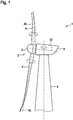
- FIG. 1 and 2 a wind power installation 1 according to the invention and thus designed to carry out the method according to the invention or its nacelle 5 is shown schematically.
- the wind energy installation 1 comprises a rotor 2 with a total of three rotor blades 4 attached to a rotor hub 3.
- the rotor 2 is rotatably arranged about a rotor axis 20 on the nacelle 5, which in turn is rotatable about a vertical axis on a tower 6 via an azimuth drive 11 is.
- the rotor hub 3 is connected via a gear 7 to a generator 8 for converting wind energy acting on the rotor 2 into electrical energy.
- the generator 8 is a double-fed asynchronous generator, in which part of the generated power is passed directly, while another part of the power is passed via a converter 9 and a switching element 10 to a transformer (not shown) located at the foot of the tower 6 and from there to a public supply network is fed in.
- a brake 12 is also provided between the gear 7 and the generator 8, with which a rotational movement of the rotor 2 about the rotor axis 20 can be braked and the rotor 2 can be locked.
- a device 13 for determining the current rotor angle a device 14 for determining the rotor speed (or the speed of the shaft between gear 7 and generator 8, which correlates directly with the rotor speed), and a device 15 for determining the wind speed in Area of the nacelle 5 and the rotor 2.
- the components 7-11 of the wind energy installation 1 which are arranged in the nacelle 5 and which can be controlled or monitored, as well as all the sensors 13, 14, 15 are connected to a control unit 16 via which the operation of the wind energy installation 1 is controlled.
- the control unit 16 is programmable and comprises a memory 17 on which control programs can be stored.
- the rotor blades 4 of the rotor 2 are pre-bent so that the rotor blades 4 can move freely in front of the tower 6 even in strong winds. Furthermore, the rotor blades 4 are each adjustable about an axis of rotation 40 with regard to their respective angle of attack.
- An electric blade adjustment drive 41 is arranged in the rotor hub 3 in each case for setting the blade pitch angle. These blade adjustment drives 41 are also controlled by the control device 16 via control lines, which are not shown for reasons of clarity. Sufficient methods for operating the wind power installation are known from the prior art, in which the angle of attack of the rotor blades is changed in order to obtain the best possible energy generation under different wind conditions.
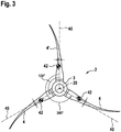
- FIG. 3 is a front view of the rotor 2 of the wind energy installation 1 from FIG Figures 1 and 2 shown, the gondola 5 and the tower 6 being omitted for reasons of clarity.
- the three rotor blades 4 all have a blade pitch angle of 90 °, that is to say they are in the flag position.
- One rotor blade 4 - namely the first rotor blade 4 '- points vertically upwards, which here corresponds to a rotor angle of 0 °.
- the other rotor blades 4 are at 120 ° and 240 °.
- the rotor blades 4 each have a mass of 8000 kg, the center of gravity 42 of the rotor blades 4 each being 20 cm outside the respective axis of rotation 40.
- the 90 ° position shown is the distance between the center of gravity 42 and the axis of rotation 40 in the plane relevant to the rotor axis 20 running perpendicular to the plane of the sheet - namely, the plane of the sheet - precisely this 20 cm.
- the counterclockwise torques of the first rotor blade 4 ′ and of the rotor blade 4 at 120 ° are compensated for by the torque of the rotor blade 4 at 240 °.
- the rotor 2 is therefore balanced. It should be noted that the rotor 2 is independent of the Rotor angle is balanced when all rotor blades 4 have the same pitch angle.
- the rotor 2 is off Figure 3 shown, but the blade pitch angle of the first rotor blade 4 'is set differently from the blade pitch angle of a second rotor blade - that is, one of the two other rotor blades 4.
- the blade pitch angle of the first rotor blade 4 ′ is -90 ° (the so-called negative vane position), so that the center of gravity 42 of the first rotor blade 40 now lies on the other side of the axis of rotation 40 at a distance of 20 cm.
- FIG. 5 it is shown schematically how the torque exerted by a rotor blade 4 on the rotor 2 can change as a function of the blade pitch angle.
- This torque results from the horizontal distance between the rotor axis 20 and the center of gravity 42, 42 'of the rotor blade 4.
- the horizontal distance or lever arm results initially from the angular position ⁇ of the axis of rotation 40 of the rotor blade 4 with respect to the 0 ° rotor angle however, influenced by the relative position of the center of gravity 42, 42 ′ with respect to the axis of rotation 40.
- FIG. 5 two exemplary center of gravity positions are shown, the center of gravity 42 representing the position at a blade pitch angle of 90 ° (ie in the vane position), the center of gravity 42 'the position at a -90 ° blade pitch angle (ie in a negative vane position).
- the two positions of the center of gravity lie apart by the distance d of 40 cm - i.e. twice the distance between the center of gravity 42, 42 'and the axis of rotation 40 - which leads to the calculation of the torque of dx cos ⁇ in a difference ⁇ l of the lever arm.
- the blade pitch angle In order to ensure that the gravitational torque generated by the setting of the deviating blade pitch angle of the first rotor blade 4 'always points in the same direction on the rotor 2 even when the rotor 2 is rotating, the blade pitch angle must be above the horizontal when the rotor blade 4' is in position be different than when the rotor blade 4 'is below the horizontal.
- Figure 7 is shown by way of example as a function of the rotor angle ⁇ which gravitational torque M tot is in the wind energy installation 1 according to FIG Figures 1 and 2 can be achieved when all rotor blades 4, 4 'of a wind energy installation 1 according to the in Figure 6 Sectors shown can be set to blade angle ⁇ of ⁇ 90 °.
- the first rotor blade (in Figure 7 marked with index "1") at a rotor blade angle ⁇ of 0 ° vertically upwards, while the second rotor blade (index "2”) is at 120 ° and the third rotor blade (index "3”) is at 240 ° (cf. Figure 3 ).
- the pitch angle of the first rotor blade ⁇ 1 is therefore + 90 °, while the pitch angle of the two other rotor blades ⁇ 2 , ⁇ 3 is -90 °.
- the rotor angle ⁇ inevitably changes and the blade pitch angles ⁇ 1 , ⁇ 2 , ⁇ 3 become as shown in FIG Figure 6 adapted to always get the maximum gravitational torque M tot .
- the rotor 2 of the wind energy installation 1 can be moved in particular when there is no wind. Also due to the different blade pitch angles of the individual rotor blades 4, 4 'in the course of the method, which can lead to undesirable loads on the wind turbine when there is wind, it is preferred if the control unit 16 only starts the method according to the invention when the device 15 for determining the Wind speed measures a wind speed of less than 3 m / s, preferably less than 2 m / s. The control unit 16 also aborts the method if the wind speed increases in its course to over 3 m / s, preferably to over 2 m / s.
- the control unit 16 also aborts the method if the rotor speed determined by the device 14 exceeds a predetermined maximum value. In both cases, the rotor blades 4, 4 'are moved in the feathered position - that is, the 90 ° position.
- the method according to the invention is particularly suitable for moving the rotor 2 into a desired angular position, for example in order to be able to carry out maintenance work on the wind energy installation 1.
- the instantaneous rotor angle recorded via the device 13 is used compared with the desired angular position and the rotor 2 is braked with the aid of the brake 12 so that the rotor 2 comes to a standstill in the desired position.
- the rotor blades 4 are moved into a low-load position, for example into the flag position, in order to avoid unnecessary loading of the brake 12.
Landscapes
- Engineering & Computer Science (AREA)
- Life Sciences & Earth Sciences (AREA)
- Sustainable Development (AREA)
- Sustainable Energy (AREA)
- Chemical & Material Sciences (AREA)
- Combustion & Propulsion (AREA)
- Mechanical Engineering (AREA)
- General Engineering & Computer Science (AREA)
- Physics & Mathematics (AREA)
- Fluid Mechanics (AREA)
- Wind Motors (AREA)
Claims (13)
- Procédé permettant de faire tourner le rotor (2) d'une éolienne (1) en cas de vent de vitesse nulle ou de vent faible insuffisant pour l'entraînement du rotor, comportant un rotor (2) pouvant tourner autour d'un axe de rotor (20) et comprenant au moins trois pales de rotor (4, 4') dont le centre de gravité (42) se situe respectivement à l'extérieur des axes de rotation (40) pour le réglage de l'angle de calage des pales de rotor individuelles (4, 4'),
l'angle de calage d'une première pale de rotor (4') étant réglé systématiquement de manière à différer de l'angle de calage d'une deuxième pale de rotor (4) pour la génération d'un déséquilibre dans le rotor (2), de telle sorte qu'un couple, dû à la gravitation, autour de l'axe de rotation (20) soit généré par la modification de la position du centre de gravité (42) de la première pale de rotor (4'). - Procédé selon la revendication 1,
caractérisé en ce que
le couple dû à la gravité généré autour de l'axe de rotation est suffisant pour surmonter un couple de démarrage existant dans la chaîne cinématique du fait des forces de friction. - Procédé selon la revendication 1 ou 2,
caractérisé en ce que
l'angle de calage d'au moins la première pale de rotor (4') est modifié en fonction de l'angle de rotor de telle sorte que le couple résultant du déséquilibre agisse dans un sens prédéfini autour de l'axe de rotor (20). - Procédé selon l'une des revendications précédentes, caractérisé en ce que
l'angle de rotation (40) pour le réglage de l'angle de calage de la première pale de rotor (4') pour la génération d'un déséquilibre diffère de l'horizontale d'au moins 5°, de préférence d'au moins 10°, de manière particulièrement préférée d'au moins 20°. - Procédé selon l'une des revendications précédentes, caractérisé en ce que
l'angle de calage d'au moins deux, de préférence de toutes les pales de rotor (4, 4') est modifié en fonction de l'angle de rotor de telle sorte que le déséquilibre du rotor (2) soit augmenté par rapport à la modification de l'angle d'attaque de seulement la première pale de rotor (4'). - Procédé selon l'une des revendications précédentes, caractérisé en ce que
pour le déplacement du rotor (2) dans une position angulaire prédéfinie, l'angle de rotor est surveillé et le déséquilibre dans le rotor (2) est réduit ou éliminé avant que la position angulaire prédéfinie ne soit atteinte ou lorsqu'elle est atteinte et/ou le rotor (2) est arrêté dans la position angulaire prédéfinie par un frein (16) . - Procédé selon l'une des revendications précédentes, caractérisé en ce
qu'avant et/ou pendant la mise en œuvre du procédé, la vitesse du vent au niveau de l'éolienne (1) est surveillée, et le procédé est interrompu en cas de vitesses du vent supérieures à 3 m/s, de préférence supérieures à 2 m/s, de manière particulièrement préférée supérieures à 1 m/s. - Procédé selon l'une des revendications précédentes, caractérisé en ce
qu'avant et/ou pendant la mise en œuvre du procédé, la vitesse de rotation du rotor (2) est surveillée, et le procédé est interrompu en cas de dépassement d'une vitesse maximale prédéfinie. - Procédé selon l'une des revendications précédentes, caractérisé en ce que
pour l'élimination du déséquilibre dans le rotor (2) et/ou en cas d'interruption du procédé, les angles d'attaque des pales de rotor (4, 4') sont réglés de manière identique, de préférence en position en drapeau. - Procédé selon l'une des revendications précédentes, caractérisé en ce que
des entraînements de réglage de pale électriques (41) sont prévus pour le réglage de l'angle de calage des pales de rotor individuelles (4, 4'). - Procédé selon l'une des revendications précédentes, caractérisé en ce que
les pales de rotor (4, 4') sont des pales de rotor précintrées. - Produit-programme d'ordinateur comportant des parties de programme qui, lorsqu'elles sont chargées dans un ordinateur, à savoir dans une unité de commande (16) d'une éolienne (1), amènent l'unité de commande (16) à mettre en œuvre un procédé selon l'une des revendications précédentes.
- Éolienne (1) comportant un rotor (2) pouvant tourner autour d'un axe de rotor (20) et comprenant au moins trois pales de rotor (4, 4') dont le centre de gravité (42) se situe respectivement à l'extérieur des axes de rotation (40) pour le réglage de l'angle de calage des pales de rotor individuelles (4, 4'), et une unité de commande (16), caractérisée en ce que l'unité de commande est conçue pour la mise en œuvre du procédé selon l'une des revendications 1 à 11.
Applications Claiming Priority (2)
| Application Number | Priority Date | Filing Date | Title |
|---|---|---|---|
| DE102017000435.8A DE102017000435A1 (de) | 2017-01-19 | 2017-01-19 | Verfahren zum Drehen des Rotors einer Windenergieanlage |
| PCT/EP2018/051256 WO2018134331A1 (fr) | 2017-01-19 | 2018-01-19 | Procédé permettant de faire tourner le rotor d'une éolienne |
Publications (2)
| Publication Number | Publication Date |
|---|---|
| EP3571400A1 EP3571400A1 (fr) | 2019-11-27 |
| EP3571400B1 true EP3571400B1 (fr) | 2021-03-24 |
Family
ID=61022342
Family Applications (1)
| Application Number | Title | Priority Date | Filing Date |
|---|---|---|---|
| EP18701151.5A Active EP3571400B1 (fr) | 2017-01-19 | 2018-01-19 | Procédé permettant de faire tourner le rotor d'une éolienne |
Country Status (7)
| Country | Link |
|---|---|
| US (1) | US20190360460A1 (fr) |
| EP (1) | EP3571400B1 (fr) |
| CN (1) | CN110475968A (fr) |
| DE (1) | DE102017000435A1 (fr) |
| DK (1) | DK3571400T3 (fr) |
| ES (1) | ES2880030T3 (fr) |
| WO (1) | WO2018134331A1 (fr) |
Families Citing this family (1)
| Publication number | Priority date | Publication date | Assignee | Title |
|---|---|---|---|---|
| CN112128053B (zh) * | 2019-06-25 | 2022-06-21 | 北京金风科创风电设备有限公司 | 叶片顺桨控制方法、风力发电机组主控制器与变桨控制器 |
Family Cites Families (8)
| Publication number | Priority date | Publication date | Assignee | Title |
|---|---|---|---|---|
| DE10031473C1 (de) * | 2000-06-28 | 2002-02-28 | Tacke Windenergie Gmbh | Vorrichtung zum Drehen einer mit einem Rotor verbundenen oder gekoppelten Welle einer Windkraftanlage |
| DE102004013624A1 (de) | 2004-03-19 | 2005-10-06 | Sb Contractor A/S | Verfahren zum Betreiben einer Windenergieanlage und Windenergieanlage |
| WO2008041066A1 (fr) * | 2006-10-02 | 2008-04-10 | Clipper Windpower Technology, Inc. | Éolienne avec commande de pas de pale afin de compenser le cisaillement du vent et le désalignement du vent |
| DE102009011603A1 (de) * | 2009-03-04 | 2010-09-09 | Klaus Würthele | Vorrichtung zur Montage von Rotorblättern an Windkraftanlagen |
| CN101988471A (zh) * | 2009-08-07 | 2011-03-23 | 王德恒 | 一种减小风力发电机叶片转动阻力的方法及叶片转动助力系统 |
| DK177326B1 (en) * | 2011-05-19 | 2013-01-07 | Envision Energy Denmark Aps | A Wind Turbine and Wind Turbine Blade |
| CN104348391A (zh) * | 2013-08-06 | 2015-02-11 | 上海万德风力发电股份有限公司 | 一种分布式低风速永磁直驱风力发电机系统 |
| EP2924284B1 (fr) * | 2014-03-28 | 2017-05-03 | Alstom Renovables España, S.L. | Contrebalancer un moyeu d'éolienne |
-
2017
- 2017-01-19 DE DE102017000435.8A patent/DE102017000435A1/de not_active Withdrawn
-
2018
- 2018-01-19 CN CN201880007531.XA patent/CN110475968A/zh active Pending
- 2018-01-19 WO PCT/EP2018/051256 patent/WO2018134331A1/fr unknown
- 2018-01-19 US US16/479,374 patent/US20190360460A1/en not_active Abandoned
- 2018-01-19 ES ES18701151T patent/ES2880030T3/es active Active
- 2018-01-19 DK DK18701151.5T patent/DK3571400T3/da active
- 2018-01-19 EP EP18701151.5A patent/EP3571400B1/fr active Active
Non-Patent Citations (1)
| Title |
|---|
| None * |
Also Published As
| Publication number | Publication date |
|---|---|
| DE102017000435A1 (de) | 2018-07-19 |
| DK3571400T3 (da) | 2021-06-07 |
| CN110475968A (zh) | 2019-11-19 |
| WO2018134331A1 (fr) | 2018-07-26 |
| US20190360460A1 (en) | 2019-11-28 |
| ES2880030T3 (es) | 2021-11-23 |
| EP3571400A1 (fr) | 2019-11-27 |
Similar Documents
| Publication | Publication Date | Title |
|---|---|---|
| EP2101058B1 (fr) | Méthode et dispositif pour tourner un composant d'une éolienne | |
| DE102006001613B4 (de) | Verfahren zum Betreiben einer Windenergieanlage und Windenergieanlage | |
| EP1286049B1 (fr) | Eolienne | |
| EP1290343B1 (fr) | Organe d'entrainement azimutal pour eoliennes | |
| EP1133638B1 (fr) | Organe d'entrainement azimutal pour eoliennes | |
| DE102010031081A1 (de) | Windenergieanlage | |
| EP3152437B1 (fr) | Éolienne et procédé pour faire fonctionner un tel équipement | |
| DE102011056543A1 (de) | Verfahren und Vorrichtung zur Herstellung eines Rotorblattes | |
| EP2923079B1 (fr) | Procédé pour faire fonctionner une éolienne et éolienne | |
| EP3571400B1 (fr) | Procédé permettant de faire tourner le rotor d'une éolienne | |
| EP2685094B1 (fr) | Commande d'un parc éolien | |
| EP2948678A1 (fr) | Procédé de réglage azimutal d'une éolienne, système de réglage azimutal et éolienne | |
| DE19920504C2 (de) | Azimutantrieb für Windenergieanlagen | |
| DE10023440C1 (de) | Azimutantrieb für Windenergieanlagen | |
| EP3814627B1 (fr) | Procédé et commande servant à faire fonctionner une éolienne | |
| EP3887677B1 (fr) | Procédé pour faire fonctionner une éolienne, éolienne et produit programme d'ordinateur | |
| EP3404256B1 (fr) | Dispositif d'ajustement des pales de rotor d'une installation génératrice d'énergie à flux | |
| EP3887676A1 (fr) | Procédé permettant de faire fonctionner une éolienne | |
| WO2011107208A2 (fr) | Procédé pour freiner une éolienne et dispositif de freinage permettant de mettre en oeuvre ce procédé | |
| WO2013149615A1 (fr) | Éolienne comprenant deux rotors | |
| WO2020109219A1 (fr) | Procédé et système permettant de faire fonctionner une éolienne | |
| WO2012079712A2 (fr) | Procédé et dispositif de commande des organes d'entraînement d'une éolienne |
Legal Events
| Date | Code | Title | Description |
|---|---|---|---|
| STAA | Information on the status of an ep patent application or granted ep patent |
Free format text: STATUS: UNKNOWN |
|
| STAA | Information on the status of an ep patent application or granted ep patent |
Free format text: STATUS: THE INTERNATIONAL PUBLICATION HAS BEEN MADE |
|
| PUAI | Public reference made under article 153(3) epc to a published international application that has entered the european phase |
Free format text: ORIGINAL CODE: 0009012 |
|
| STAA | Information on the status of an ep patent application or granted ep patent |
Free format text: STATUS: REQUEST FOR EXAMINATION WAS MADE |
|
| 17P | Request for examination filed |
Effective date: 20190702 |
|
| AK | Designated contracting states |
Kind code of ref document: A1 Designated state(s): AL AT BE BG CH CY CZ DE DK EE ES FI FR GB GR HR HU IE IS IT LI LT LU LV MC MK MT NL NO PL PT RO RS SE SI SK SM TR |
|
| AX | Request for extension of the european patent |
Extension state: BA ME |
|
| DAV | Request for validation of the european patent (deleted) | ||
| DAX | Request for extension of the european patent (deleted) | ||
| GRAP | Despatch of communication of intention to grant a patent |
Free format text: ORIGINAL CODE: EPIDOSNIGR1 |
|
| STAA | Information on the status of an ep patent application or granted ep patent |
Free format text: STATUS: GRANT OF PATENT IS INTENDED |
|
| INTG | Intention to grant announced |
Effective date: 20200908 |
|
| GRAS | Grant fee paid |
Free format text: ORIGINAL CODE: EPIDOSNIGR3 |
|
| STAA | Information on the status of an ep patent application or granted ep patent |
Free format text: STATUS: GRANT OF PATENT IS INTENDED |
|
| GRAA | (expected) grant |
Free format text: ORIGINAL CODE: 0009210 |
|
| STAA | Information on the status of an ep patent application or granted ep patent |
Free format text: STATUS: THE PATENT HAS BEEN GRANTED |
|
| RAP1 | Party data changed (applicant data changed or rights of an application transferred) |
Owner name: SIEMENS GAMESA RENEWABLE ENERGY SERVICE GMBH |
|
| AK | Designated contracting states |
Kind code of ref document: B1 Designated state(s): AL AT BE BG CH CY CZ DE DK EE ES FI FR GB GR HR HU IE IS IT LI LT LU LV MC MK MT NL NO PL PT RO RS SE SI SK SM TR |
|
| REG | Reference to a national code |
Ref country code: GB Ref legal event code: FG4D Free format text: NOT ENGLISH |
|
| REG | Reference to a national code |
Ref country code: CH Ref legal event code: EP |
|
| REG | Reference to a national code |
Ref country code: DE Ref legal event code: R096 Ref document number: 502018004437 Country of ref document: DE |
|
| REG | Reference to a national code |
Ref country code: IE Ref legal event code: FG4D Free format text: LANGUAGE OF EP DOCUMENT: GERMAN |
|
| REG | Reference to a national code |
Ref country code: AT Ref legal event code: REF Ref document number: 1374742 Country of ref document: AT Kind code of ref document: T Effective date: 20210415 |
|
| REG | Reference to a national code |
Ref country code: DK Ref legal event code: T3 Effective date: 20210531 |
|
| REG | Reference to a national code |
Ref country code: LT Ref legal event code: MG9D |
|
| PG25 | Lapsed in a contracting state [announced via postgrant information from national office to epo] |
Ref country code: NO Free format text: LAPSE BECAUSE OF FAILURE TO SUBMIT A TRANSLATION OF THE DESCRIPTION OR TO PAY THE FEE WITHIN THE PRESCRIBED TIME-LIMIT Effective date: 20210624 Ref country code: FI Free format text: LAPSE BECAUSE OF FAILURE TO SUBMIT A TRANSLATION OF THE DESCRIPTION OR TO PAY THE FEE WITHIN THE PRESCRIBED TIME-LIMIT Effective date: 20210324 Ref country code: HR Free format text: LAPSE BECAUSE OF FAILURE TO SUBMIT A TRANSLATION OF THE DESCRIPTION OR TO PAY THE FEE WITHIN THE PRESCRIBED TIME-LIMIT Effective date: 20210324 Ref country code: GR Free format text: LAPSE BECAUSE OF FAILURE TO SUBMIT A TRANSLATION OF THE DESCRIPTION OR TO PAY THE FEE WITHIN THE PRESCRIBED TIME-LIMIT Effective date: 20210625 Ref country code: BG Free format text: LAPSE BECAUSE OF FAILURE TO SUBMIT A TRANSLATION OF THE DESCRIPTION OR TO PAY THE FEE WITHIN THE PRESCRIBED TIME-LIMIT Effective date: 20210624 |
|
| PG25 | Lapsed in a contracting state [announced via postgrant information from national office to epo] |
Ref country code: RS Free format text: LAPSE BECAUSE OF FAILURE TO SUBMIT A TRANSLATION OF THE DESCRIPTION OR TO PAY THE FEE WITHIN THE PRESCRIBED TIME-LIMIT Effective date: 20210324 Ref country code: LV Free format text: LAPSE BECAUSE OF FAILURE TO SUBMIT A TRANSLATION OF THE DESCRIPTION OR TO PAY THE FEE WITHIN THE PRESCRIBED TIME-LIMIT Effective date: 20210324 Ref country code: SE Free format text: LAPSE BECAUSE OF FAILURE TO SUBMIT A TRANSLATION OF THE DESCRIPTION OR TO PAY THE FEE WITHIN THE PRESCRIBED TIME-LIMIT Effective date: 20210324 |
|
| REG | Reference to a national code |
Ref country code: NL Ref legal event code: MP Effective date: 20210324 |
|
| PG25 | Lapsed in a contracting state [announced via postgrant information from national office to epo] |
Ref country code: NL Free format text: LAPSE BECAUSE OF FAILURE TO SUBMIT A TRANSLATION OF THE DESCRIPTION OR TO PAY THE FEE WITHIN THE PRESCRIBED TIME-LIMIT Effective date: 20210324 |
|
| PG25 | Lapsed in a contracting state [announced via postgrant information from national office to epo] |
Ref country code: LT Free format text: LAPSE BECAUSE OF FAILURE TO SUBMIT A TRANSLATION OF THE DESCRIPTION OR TO PAY THE FEE WITHIN THE PRESCRIBED TIME-LIMIT Effective date: 20210324 Ref country code: EE Free format text: LAPSE BECAUSE OF FAILURE TO SUBMIT A TRANSLATION OF THE DESCRIPTION OR TO PAY THE FEE WITHIN THE PRESCRIBED TIME-LIMIT Effective date: 20210324 Ref country code: CZ Free format text: LAPSE BECAUSE OF FAILURE TO SUBMIT A TRANSLATION OF THE DESCRIPTION OR TO PAY THE FEE WITHIN THE PRESCRIBED TIME-LIMIT Effective date: 20210324 Ref country code: SM Free format text: LAPSE BECAUSE OF FAILURE TO SUBMIT A TRANSLATION OF THE DESCRIPTION OR TO PAY THE FEE WITHIN THE PRESCRIBED TIME-LIMIT Effective date: 20210324 |
|
| REG | Reference to a national code |
Ref country code: ES Ref legal event code: FG2A Ref document number: 2880030 Country of ref document: ES Kind code of ref document: T3 Effective date: 20211123 |
|
| PG25 | Lapsed in a contracting state [announced via postgrant information from national office to epo] |
Ref country code: IS Free format text: LAPSE BECAUSE OF FAILURE TO SUBMIT A TRANSLATION OF THE DESCRIPTION OR TO PAY THE FEE WITHIN THE PRESCRIBED TIME-LIMIT Effective date: 20210724 Ref country code: PT Free format text: LAPSE BECAUSE OF FAILURE TO SUBMIT A TRANSLATION OF THE DESCRIPTION OR TO PAY THE FEE WITHIN THE PRESCRIBED TIME-LIMIT Effective date: 20210726 Ref country code: PL Free format text: LAPSE BECAUSE OF FAILURE TO SUBMIT A TRANSLATION OF THE DESCRIPTION OR TO PAY THE FEE WITHIN THE PRESCRIBED TIME-LIMIT Effective date: 20210324 Ref country code: SK Free format text: LAPSE BECAUSE OF FAILURE TO SUBMIT A TRANSLATION OF THE DESCRIPTION OR TO PAY THE FEE WITHIN THE PRESCRIBED TIME-LIMIT Effective date: 20210324 Ref country code: RO Free format text: LAPSE BECAUSE OF FAILURE TO SUBMIT A TRANSLATION OF THE DESCRIPTION OR TO PAY THE FEE WITHIN THE PRESCRIBED TIME-LIMIT Effective date: 20210324 |
|
| REG | Reference to a national code |
Ref country code: DE Ref legal event code: R097 Ref document number: 502018004437 Country of ref document: DE |
|
| PG25 | Lapsed in a contracting state [announced via postgrant information from national office to epo] |
Ref country code: AL Free format text: LAPSE BECAUSE OF FAILURE TO SUBMIT A TRANSLATION OF THE DESCRIPTION OR TO PAY THE FEE WITHIN THE PRESCRIBED TIME-LIMIT Effective date: 20210324 |
|
| PLBE | No opposition filed within time limit |
Free format text: ORIGINAL CODE: 0009261 |
|
| STAA | Information on the status of an ep patent application or granted ep patent |
Free format text: STATUS: NO OPPOSITION FILED WITHIN TIME LIMIT |
|
| PG25 | Lapsed in a contracting state [announced via postgrant information from national office to epo] |
Ref country code: SI Free format text: LAPSE BECAUSE OF FAILURE TO SUBMIT A TRANSLATION OF THE DESCRIPTION OR TO PAY THE FEE WITHIN THE PRESCRIBED TIME-LIMIT Effective date: 20210324 |
|
| 26N | No opposition filed |
Effective date: 20220104 |
|
| RAP4 | Party data changed (patent owner data changed or rights of a patent transferred) |
Owner name: SIEMENS GAMESA RENEWABLE ENERGY SERVICE GMBH |
|
| PG25 | Lapsed in a contracting state [announced via postgrant information from national office to epo] |
Ref country code: IS Free format text: LAPSE BECAUSE OF FAILURE TO SUBMIT A TRANSLATION OF THE DESCRIPTION OR TO PAY THE FEE WITHIN THE PRESCRIBED TIME-LIMIT Effective date: 20210724 |
|
| PG25 | Lapsed in a contracting state [announced via postgrant information from national office to epo] |
Ref country code: MC Free format text: LAPSE BECAUSE OF FAILURE TO SUBMIT A TRANSLATION OF THE DESCRIPTION OR TO PAY THE FEE WITHIN THE PRESCRIBED TIME-LIMIT Effective date: 20210324 |
|
| REG | Reference to a national code |
Ref country code: CH Ref legal event code: PL |
|
| REG | Reference to a national code |
Ref country code: BE Ref legal event code: MM Effective date: 20220131 |
|
| PG25 | Lapsed in a contracting state [announced via postgrant information from national office to epo] |
Ref country code: LU Free format text: LAPSE BECAUSE OF NON-PAYMENT OF DUE FEES Effective date: 20220119 |
|
| PG25 | Lapsed in a contracting state [announced via postgrant information from national office to epo] |
Ref country code: FR Free format text: LAPSE BECAUSE OF NON-PAYMENT OF DUE FEES Effective date: 20220131 Ref country code: BE Free format text: LAPSE BECAUSE OF NON-PAYMENT OF DUE FEES Effective date: 20220131 |
|
| PG25 | Lapsed in a contracting state [announced via postgrant information from national office to epo] |
Ref country code: LI Free format text: LAPSE BECAUSE OF NON-PAYMENT OF DUE FEES Effective date: 20220131 Ref country code: CH Free format text: LAPSE BECAUSE OF NON-PAYMENT OF DUE FEES Effective date: 20220131 |
|
| PG25 | Lapsed in a contracting state [announced via postgrant information from national office to epo] |
Ref country code: IT Free format text: LAPSE BECAUSE OF FAILURE TO SUBMIT A TRANSLATION OF THE DESCRIPTION OR TO PAY THE FEE WITHIN THE PRESCRIBED TIME-LIMIT Effective date: 20210324 Ref country code: IE Free format text: LAPSE BECAUSE OF NON-PAYMENT OF DUE FEES Effective date: 20220119 |
|
| REG | Reference to a national code |
Ref country code: AT Ref legal event code: MM01 Ref document number: 1374742 Country of ref document: AT Kind code of ref document: T Effective date: 20230119 |
|
| PGFP | Annual fee paid to national office [announced via postgrant information from national office to epo] |
Ref country code: ES Payment date: 20240216 Year of fee payment: 7 |
|
| PG25 | Lapsed in a contracting state [announced via postgrant information from national office to epo] |
Ref country code: AT Free format text: LAPSE BECAUSE OF NON-PAYMENT OF DUE FEES Effective date: 20230119 |
|
| PG25 | Lapsed in a contracting state [announced via postgrant information from national office to epo] |
Ref country code: MK Free format text: LAPSE BECAUSE OF FAILURE TO SUBMIT A TRANSLATION OF THE DESCRIPTION OR TO PAY THE FEE WITHIN THE PRESCRIBED TIME-LIMIT Effective date: 20210324 Ref country code: CY Free format text: LAPSE BECAUSE OF FAILURE TO SUBMIT A TRANSLATION OF THE DESCRIPTION OR TO PAY THE FEE WITHIN THE PRESCRIBED TIME-LIMIT Effective date: 20210324 Ref country code: AT Free format text: LAPSE BECAUSE OF NON-PAYMENT OF DUE FEES Effective date: 20230119 |
|
| PGFP | Annual fee paid to national office [announced via postgrant information from national office to epo] |
Ref country code: DE Payment date: 20240119 Year of fee payment: 7 Ref country code: GB Payment date: 20240117 Year of fee payment: 7 |
|
| PG25 | Lapsed in a contracting state [announced via postgrant information from national office to epo] |
Ref country code: HU Free format text: LAPSE BECAUSE OF FAILURE TO SUBMIT A TRANSLATION OF THE DESCRIPTION OR TO PAY THE FEE WITHIN THE PRESCRIBED TIME-LIMIT; INVALID AB INITIO Effective date: 20180119 |
|
| PGFP | Annual fee paid to national office [announced via postgrant information from national office to epo] |
Ref country code: DK Payment date: 20240123 Year of fee payment: 7 |
|
| PG25 | Lapsed in a contracting state [announced via postgrant information from national office to epo] |
Ref country code: TR Free format text: LAPSE BECAUSE OF FAILURE TO SUBMIT A TRANSLATION OF THE DESCRIPTION OR TO PAY THE FEE WITHIN THE PRESCRIBED TIME-LIMIT Effective date: 20210324 |
|
| PG25 | Lapsed in a contracting state [announced via postgrant information from national office to epo] |
Ref country code: MT Free format text: LAPSE BECAUSE OF FAILURE TO SUBMIT A TRANSLATION OF THE DESCRIPTION OR TO PAY THE FEE WITHIN THE PRESCRIBED TIME-LIMIT Effective date: 20210324 |