EP3571138B1 - Fluid medium dispensing system and a method of assembling a dispensing system for a fluid medium - Google Patents
Fluid medium dispensing system and a method of assembling a dispensing system for a fluid medium Download PDFInfo
- Publication number
- EP3571138B1 EP3571138B1 EP17701441.2A EP17701441A EP3571138B1 EP 3571138 B1 EP3571138 B1 EP 3571138B1 EP 17701441 A EP17701441 A EP 17701441A EP 3571138 B1 EP3571138 B1 EP 3571138B1
- Authority
- EP
- European Patent Office
- Prior art keywords
- container
- valve cup
- neck
- valve
- opening
- Prior art date
- Legal status (The legal status is an assumption and is not a legal conclusion. Google has not performed a legal analysis and makes no representation as to the accuracy of the status listed.)
- Active
Links
- 239000012530 fluid Substances 0.000 title claims description 42
- 238000000034 method Methods 0.000 title claims description 26
- 229920003023 plastic Polymers 0.000 claims description 49
- 239000000463 material Substances 0.000 claims description 45
- 239000004033 plastic Substances 0.000 claims description 44
- 238000003466 welding Methods 0.000 claims description 17
- 238000003825 pressing Methods 0.000 claims description 12
- 239000003380 propellant Substances 0.000 claims description 12
- 238000007789 sealing Methods 0.000 claims description 11
- 239000000203 mixture Substances 0.000 claims description 8
- -1 polypropylene Polymers 0.000 claims description 8
- NLHHRLWOUZZQLW-UHFFFAOYSA-N Acrylonitrile Chemical compound C=CC#N NLHHRLWOUZZQLW-UHFFFAOYSA-N 0.000 claims description 6
- 239000004743 Polypropylene Substances 0.000 claims description 6
- 229920001155 polypropylene Polymers 0.000 claims description 6
- 230000002093 peripheral effect Effects 0.000 claims description 4
- 230000015572 biosynthetic process Effects 0.000 claims description 3
- 229920000139 polyethylene terephthalate Polymers 0.000 description 22
- 239000005020 polyethylene terephthalate Substances 0.000 description 22
- 229920000728 polyester Polymers 0.000 description 15
- 230000008901 benefit Effects 0.000 description 6
- 239000007789 gas Substances 0.000 description 6
- 229920006126 semicrystalline polymer Polymers 0.000 description 5
- 229910052751 metal Inorganic materials 0.000 description 4
- 239000002184 metal Substances 0.000 description 4
- 239000000654 additive Substances 0.000 description 3
- 239000004411 aluminium Substances 0.000 description 3
- 229910052782 aluminium Inorganic materials 0.000 description 3
- XAGFODPZIPBFFR-UHFFFAOYSA-N aluminium Chemical compound [Al] XAGFODPZIPBFFR-UHFFFAOYSA-N 0.000 description 3
- 238000004891 communication Methods 0.000 description 3
- 238000004519 manufacturing process Methods 0.000 description 3
- 238000004806 packaging method and process Methods 0.000 description 3
- 229920000642 polymer Polymers 0.000 description 3
- IJGRMHOSHXDMSA-UHFFFAOYSA-N Atomic nitrogen Chemical compound N#N IJGRMHOSHXDMSA-UHFFFAOYSA-N 0.000 description 2
- 239000000853 adhesive Substances 0.000 description 2
- 230000001070 adhesive effect Effects 0.000 description 2
- 239000006229 carbon black Substances 0.000 description 2
- 239000003086 colorant Substances 0.000 description 2
- 230000008878 coupling Effects 0.000 description 2
- 238000010168 coupling process Methods 0.000 description 2
- 238000005859 coupling reaction Methods 0.000 description 2
- 239000002178 crystalline material Substances 0.000 description 2
- 230000001419 dependent effect Effects 0.000 description 2
- 239000000049 pigment Substances 0.000 description 2
- 101100327917 Caenorhabditis elegans chup-1 gene Proteins 0.000 description 1
- 238000010521 absorption reaction Methods 0.000 description 1
- 230000002411 adverse Effects 0.000 description 1
- 239000000443 aerosol Substances 0.000 description 1
- 239000011324 bead Substances 0.000 description 1
- 230000000694 effects Effects 0.000 description 1
- 230000001747 exhibiting effect Effects 0.000 description 1
- 238000003780 insertion Methods 0.000 description 1
- 230000037431 insertion Effects 0.000 description 1
- 239000007788 liquid Substances 0.000 description 1
- 239000000155 melt Substances 0.000 description 1
- 229910052757 nitrogen Inorganic materials 0.000 description 1
- 238000012536 packaging technology Methods 0.000 description 1
- 230000001681 protective effect Effects 0.000 description 1
- 230000005855 radiation Effects 0.000 description 1
- 238000005728 strengthening Methods 0.000 description 1
- 229920001169 thermoplastic Polymers 0.000 description 1
- 239000004416 thermosoftening plastic Substances 0.000 description 1
- 238000011144 upstream manufacturing Methods 0.000 description 1
Images

Classifications
-
- B—PERFORMING OPERATIONS; TRANSPORTING
- B65—CONVEYING; PACKING; STORING; HANDLING THIN OR FILAMENTARY MATERIAL
- B65D—CONTAINERS FOR STORAGE OR TRANSPORT OF ARTICLES OR MATERIALS, e.g. BAGS, BARRELS, BOTTLES, BOXES, CANS, CARTONS, CRATES, DRUMS, JARS, TANKS, HOPPERS, FORWARDING CONTAINERS; ACCESSORIES, CLOSURES, OR FITTINGS THEREFOR; PACKAGING ELEMENTS; PACKAGES
- B65D83/00—Containers or packages with special means for dispensing contents
- B65D83/14—Containers or packages with special means for dispensing contents for delivery of liquid or semi-liquid contents by internal gaseous pressure, i.e. aerosol containers comprising propellant for a product delivered by a propellant
- B65D83/38—Details of the container body
-
- B—PERFORMING OPERATIONS; TRANSPORTING
- B65—CONVEYING; PACKING; STORING; HANDLING THIN OR FILAMENTARY MATERIAL
- B65D—CONTAINERS FOR STORAGE OR TRANSPORT OF ARTICLES OR MATERIALS, e.g. BAGS, BARRELS, BOTTLES, BOXES, CANS, CARTONS, CRATES, DRUMS, JARS, TANKS, HOPPERS, FORWARDING CONTAINERS; ACCESSORIES, CLOSURES, OR FITTINGS THEREFOR; PACKAGING ELEMENTS; PACKAGES
- B65D83/00—Containers or packages with special means for dispensing contents
- B65D83/14—Containers or packages with special means for dispensing contents for delivery of liquid or semi-liquid contents by internal gaseous pressure, i.e. aerosol containers comprising propellant for a product delivered by a propellant
- B65D83/60—Contents and propellant separated
- B65D83/62—Contents and propellant separated by membrane, bag, or the like
-
- B—PERFORMING OPERATIONS; TRANSPORTING
- B29—WORKING OF PLASTICS; WORKING OF SUBSTANCES IN A PLASTIC STATE IN GENERAL
- B29C—SHAPING OR JOINING OF PLASTICS; SHAPING OF MATERIAL IN A PLASTIC STATE, NOT OTHERWISE PROVIDED FOR; AFTER-TREATMENT OF THE SHAPED PRODUCTS, e.g. REPAIRING
- B29C2949/00—Indexing scheme relating to blow-moulding
- B29C2949/07—Preforms or parisons characterised by their configuration
- B29C2949/076—Preforms or parisons characterised by their configuration characterised by the shape
- B29C2949/0768—Preforms or parisons characterised by their configuration characterised by the shape characterised by the shape of specific parts of preform
- B29C2949/0769—Preforms or parisons characterised by their configuration characterised by the shape characterised by the shape of specific parts of preform characterised by the lip, i.e. very top of preform neck
-
- B—PERFORMING OPERATIONS; TRANSPORTING
- B29—WORKING OF PLASTICS; WORKING OF SUBSTANCES IN A PLASTIC STATE IN GENERAL
- B29C—SHAPING OR JOINING OF PLASTICS; SHAPING OF MATERIAL IN A PLASTIC STATE, NOT OTHERWISE PROVIDED FOR; AFTER-TREATMENT OF THE SHAPED PRODUCTS, e.g. REPAIRING
- B29C2949/00—Indexing scheme relating to blow-moulding
- B29C2949/20—Preforms or parisons whereby a specific part is made of only one component, e.g. only one layer
- B29C2949/22—Preforms or parisons whereby a specific part is made of only one component, e.g. only one layer at neck portion
-
- B—PERFORMING OPERATIONS; TRANSPORTING
- B65—CONVEYING; PACKING; STORING; HANDLING THIN OR FILAMENTARY MATERIAL
- B65D—CONTAINERS FOR STORAGE OR TRANSPORT OF ARTICLES OR MATERIALS, e.g. BAGS, BARRELS, BOTTLES, BOXES, CANS, CARTONS, CRATES, DRUMS, JARS, TANKS, HOPPERS, FORWARDING CONTAINERS; ACCESSORIES, CLOSURES, OR FITTINGS THEREFOR; PACKAGING ELEMENTS; PACKAGES
- B65D83/00—Containers or packages with special means for dispensing contents
- B65D83/14—Containers or packages with special means for dispensing contents for delivery of liquid or semi-liquid contents by internal gaseous pressure, i.e. aerosol containers comprising propellant for a product delivered by a propellant
- B65D83/42—Filling or charging means
- B65D83/425—Delivery valves permitting filling or charging
-
- B—PERFORMING OPERATIONS; TRANSPORTING
- B65—CONVEYING; PACKING; STORING; HANDLING THIN OR FILAMENTARY MATERIAL
- B65D—CONTAINERS FOR STORAGE OR TRANSPORT OF ARTICLES OR MATERIALS, e.g. BAGS, BARRELS, BOTTLES, BOXES, CANS, CARTONS, CRATES, DRUMS, JARS, TANKS, HOPPERS, FORWARDING CONTAINERS; ACCESSORIES, CLOSURES, OR FITTINGS THEREFOR; PACKAGING ELEMENTS; PACKAGES
- B65D83/00—Containers or packages with special means for dispensing contents
- B65D83/14—Containers or packages with special means for dispensing contents for delivery of liquid or semi-liquid contents by internal gaseous pressure, i.e. aerosol containers comprising propellant for a product delivered by a propellant
- B65D83/44—Valves specially adapted therefor; Regulating devices
- B65D83/48—Lift valves, e.g. operated by push action
-
- B—PERFORMING OPERATIONS; TRANSPORTING
- B65—CONVEYING; PACKING; STORING; HANDLING THIN OR FILAMENTARY MATERIAL
- B65D—CONTAINERS FOR STORAGE OR TRANSPORT OF ARTICLES OR MATERIALS, e.g. BAGS, BARRELS, BOTTLES, BOXES, CANS, CARTONS, CRATES, DRUMS, JARS, TANKS, HOPPERS, FORWARDING CONTAINERS; ACCESSORIES, CLOSURES, OR FITTINGS THEREFOR; PACKAGING ELEMENTS; PACKAGES
- B65D83/00—Containers or packages with special means for dispensing contents
- B65D83/14—Containers or packages with special means for dispensing contents for delivery of liquid or semi-liquid contents by internal gaseous pressure, i.e. aerosol containers comprising propellant for a product delivered by a propellant
- B65D83/68—Dispensing two or more contents, e.g. sequential dispensing or simultaneous dispensing of two or more products without mixing them
Definitions
- the present invention relates to an improvement in sealing performance and attachment between a valve cup and a container for dispensing a fluid medium stored under pressure and also to a method of assembling such a dispensing system for dispensing a fluid medium stored under pressure.
- Systems for dispensing a fluid medium stored under pressure are well-known and typically include a container, a valve, and a valve cup, wherein the valve cup supports the valve, usually centrally, and also closes off an opening of the container.
- the inner volume of the container is pressurized and maintained in such a state by the valve and seals between the valve cup and valve, and the valve cup and the container opening.
- the pressure difference between the inner volume of the container and the outside environment causes the fluid medium to be expelled from the container.
- Some systems employ a two-stage container having an inner and outer container, one of which contains the propellant gas, whereas others may employ a single container with the fluid medium also acting as the propellant.
- the containers are made from a metal, usually aluminium.
- PET polyethylene terephthalate
- PET containers also typically use a metal, e.g., aluminium, for the valve cups which ensures a suitable sealing engagement between the valve cup and valve.
- the valve cup may be clinched to a lip of the opening of the container. While the attachment between the valve cup and container is often sufficient at most normal operating temperatures, higher temperatures can cause the PET container to deform to a large degree such that the connection between the aluminium valve cup and container opening is no longer fluid tight. This is highly disadvantageous as the propellant gas and/or the fluid medium can escape from the container.
- a dispensing system exhibiting sufficient sealing performance at temperatures greater than 50°C is therefore required that enables the container and the valve cup to be made using plastics materials in order to take advantage of the considerable benefits of these materials.
- a fluid medium dispensing system comprising:
- valve cup to the neck of the container by a molten weld seam formed by laser welding not only secures the valve cup in position but also creates a seal that enables the dispensing system to withstand internal pressures of up to 13 bar.
- a seal has the advantage that it is simple and economical to employ.
- the plastics material of the neck of the container is laser-transparent and the plastics material of the valve cup is laser-absorbing.
- the laser welding of the valve cup to the neck of container involves passing a focused laser beam through the neck of the container to strike the interface between the neck and the valve cup. At the interface the laser light is turned into heat energy as it is absorbed by the plastics material of the valve cup. The heat created melts the plastics material at the interface in order to create the molten weld seam, which fuses the plastics materials of the valve cup and the neck together.
- Most thermoplastics transmit infrared laser radiation so laser light with a wavelength of either 980nm or 808nm is usually used as more energy is transmitted at these wavelengths. However, the plastics material of the valve cup must turn the light energy into heat and must therefore absorb the laser light.
- the plastics material of the valve cup is preferably laser-absorbing as opposed to laser-transparent.
- Additives are usually used to achieve this by providing light absorbing qualities. Most often carbon black is used, but many additives will promote absorption including various pigments and fills as will be known to those skilled in the art. It should also be noted that be that laser-transparent plastics material of the neck of the container can still be colored and even opaque if special non-absorbing colorants are used.
- the plastics material of the valve cup is a semi-crystalline polymer. It has been found that fully crystallized plastics materials tends to lose their shape during laser welding owing to the high temperatures reached. This is not the case when only semi-crystallized plastics material is used.
- Semi-crystalline polyesters have a greater degree of crystallinity when compared to more amorphous polyesters and they do not deform when exposed to temperatures greater than 50°C.
- Crystallized PET (CPET), PBT, PEN, and PEN/PET copolymers are or can be semi-crystalline polyesters. These materials are particularly advantageous for their other properties in packaging and not just their rigidity at elevated temperatures.
- any polyester that can be semi-crystalline and does not deform to a suitable degree at large temperatures may also be used as the semi-crystalline material.
- any blend of CPET, PBT, PEN, and PEN/PET may be used.
- the plastics material of the valve cup is selected from a group consisting of semi-crystallized PET, PBT, PEN, PEN/PET copolymers, POM, acrylonitrile, polypropylene, or a blend of any of the foregoing.
- the plastics material of the neck of the container is selected from a group consisting of: crystallized PET, PBT, PEN, PEN/PET copolymers, POM, acrylonitrile, polypropylene, or a blend of any of the foregoing.
- the whole of the valve cup is comprised of one or more laser-absorbing semi-crystalline polymers.
- the whole of the container is comprised of a laser-transparent plastics material.
- a method of assembling a dispensing system for dispensing a fluid medium stored under pressure including:
- a bag is attached to the valve such that its inner volume is in fluid communication with channels upstream and downstream of the valve when the valve is actuated and therefore open but is not in fluid communication with an interior volume of the container between the inside wall of the container and the outside surface of the bag.
- the bag contains the fluid medium to be dispensed by the system and the interior volume between the inside wall of the container and the outside surface of the bag contains a pressurized gas for use as a propellant.
- Bag-on-valve (BoV) packaging technologies are advantageously used for many consumer products, in particular for pharmaceutical and healthcare products. They have many advantages, in particular there is no need to use flammable propellants and they can be used with pressurized air or nitrogen. This is particularly important in the present invention as such a propellant will not have an adverse effect on the adhesive seal between the valve cup and the neck of the container.
- the method comprises the additional steps of providing a bag, attaching the valve to an opening of the bag, fluidly sealing the bag to the valve and inserting the bag into the container.
- the valve cup is an interference fit in the neck of the container with contact between said plastics materials of the valve cup and of the neck around the whole periphery of the valve cup. Such peripheral contact between the valve cup and the neck ensures that the molten weld seam formed during laser welding is secure around the totality of the opening in the neck that is closed by the valve cup.
- valve cup is pressed into the neck of the container during assembly with a force between 343 and 442 N, that is with a force between approximately 35 and 45 kg force.
- the valve cup comprises an inner part that is located in the opening of the container and the outer diameter of the inner part of the valve cup prior to pressing of the valve cup into the opening of the container is between 0.05 mm and 0.15 mm inclusive, and in particular 0.10 mm, greater than the inner diameter of the opening in order to create the interference fit.
- the molten weld seam is preferably located between the inner part of the valve cup that is pressed into the opening of the container and the neck of the container.
- the valve cup comprises an outer, annular part that defines a U-shape in which a rim of the neck of the container is located.
- the molten weld seam or an additional molten weld seam is preferably located between the rim of the neck of the container and the U-shaped, outer annular part of the valve cup.
- Plastic containers may be advantageous for various reasons when compared to metal containers, e.g., because of cost or ease of manufacturing.
- Polyesters, and in particular PET have many advantageous qualities in packaging applications. They can be easy to manipulate and thus forming containers of PET may be relatively easier and quicker than forming them of metal. In some cases, the polyesters may also be relatively cheap. Some polyesters can also be recycled thus reducing the overall overhead cost. Finally, some polyesters can also be sterilized which is particularly advantageous for medical applications.
- At least the neck of the container is preferably formed from a first plastics material, which is preferably a polyester.
- the container is formed from plastics material selected from a group consisting of: crystallized PET, PBT, PEN, PEN/PET copolymers, POM, acrylonitrile, polypropylene, or a blend of any of the foregoing.
- valve cup is either formed from a semi-crystalline polyester or includes a lining formed from a semi-crystalline polyester, which lining comprises the aforesaid portion of the valve cup that is contiguous with the neck of the container.
- Fig. 1 shows an example of a fluid medium dispensing system 1 in accordance with the present invention.
- the dispensing system 1 includes a valve cup 2, a container 3, and a valve 4.
- the inner region of the container 3 is pressurized to a pressure greater than atmospheric pressure.
- this pressure is typically around 7 bar although the pressure is not limited to this value and may take any desired value limited only by regional or governmental restrictions.
- the valve 4 is generally held in a fixed position by the valve cup 2 such that when a force is applied to the valve 4 by a user, the valve 4 is actuated to an open position. In this position, the pressure difference within and without the container 3 causes the fluid medium to be distributed from the container 3 via the valve 4.
- the valve 4 is not shown in any detail in the drawings as any suitable known valve can be used.
- the container 3 comprises a neck 5 defining an opening 6 in which the valve cup 2 is inserted.
- the neck 5 also includes a rim 7 that preferably comprises an annular lip 8.
- the valve cup 2 comprises a first, inner part 9 that is located in the opening 6 of the container 3 and a second, annular part 10 that covers the rim 7.
- the first part 9 is adapted to retain the valve 4 in a conventional manner and a plurality of strengthening ribs 11 may be provided located between the first and second parts 9 and 10.
- the first part 9 is an interference fit into the opening 6 of the neck 5 around the whole periphery of the first part 9.
- the outer diameter of the first part 9 and the diameter of the opening 6 are therefore predetermined in order to control the degree of force required to push-fit the first part of the valve cup 2 into the opening 6.
- the outer diameter of the inner part 9 is between 0.05 mm and 0.15 mm inclusive, and in particular 0.10 mm, greater than the inner diameter of the opening 6 prior to pressing of the first part 9 into the opening 6 in order to create the interference fit.
- the valve cup 2 is pressed into the opening 6 of the neck 5 with a force that is between 343 and 442 N, that is with a force between approximately 35 and 45 kg force.
- the force is preferably around 392 N, that is about 40 kg force.
- the second part 10 of the valve cup 2 is preferably snap-fitted over the rim 7 of the neck 5.
- the second, annular part 10 of the valve cup 2 is formed in an inverted U-shape in which the rim 7 of the neck 5 of the container 3 locates.
- the U-shaped second part 10 comprises at least one protrusion 12 on a surface of an outer leg 13 of the U-shape that faces the neck 5 of the container.
- the protrusion 12 preferably takes the form of an annular bead that is adapted to frictionally engage the neck 5 and to snap-fit over the rim 7 by engagement over and around the lip 8.
- the U-shaped second part 10 comprises an inner leg 14 that lies contiguous with the inner surface of the neck 5 to a level below that of the outer leg 13 and the snap-fitment between the protrusion 12 and the rim 7.
- the inner leg 14 and the neck 5 are contiguous around the whole periphery of the first part 9 of the valve cup 1 that is inserted into the neck 5. This is important because the container 3 is sealed after pressurization, as is described below, by laser welding of the valve cup 2 to the container 3. During this process the contiguous parts of the valve cup 2 and the container 3 are fused to form a molten weld seam 15a and/or 15b.
- the seam 15a, 15b seals the container 3 and the peripheral contact between the first part 9 of the valve cup and the neck 5 ensures that the molten weld seam 15a, 15b is secure around the totality of the opening in the neck 5 that is closed by the first part 9 of the valve cup 2.
- the contiguous parts of the valve cup 2 and the neck must be made of plastics material as the welding process generates heat that causes these parts to fuse together to form the molten weld seam 15a, 15b.
- a focused laser beam shown by the labelled arrow 17 in Fig. 1 , is directed at the contiguous parts of the valve cup 2 and the container 3.
- the molten weld seam 15a is located between the inner part 9 of the valve cup 2 that is pressed into the opening 6 of the container 3 and the neck 5 of the container below the rim 7.
- the molten weld seam 15b is located between the rim 7 of the neck 5 of the container 3 and the U-shaped, outer annular part 13 of the valve cup 2.
- two molten weld seams 15a and 15b are formed per container 3 in both of the aforesaid locations.
- the laser beam or beams are focused on the relevant interface or interfaces between the neck 5 and the valve cup 2.
- the plastics material of the neck 5 of the container 3 is preferably laser-transparent whereas the plastics material of the valve cup 2 is preferably laser-absorbing.
- the whole of the valve cup 2 is comprised of one or more laser-absorbing polymers.
- the whole of the valve cup 2 is comprised of one or more laser-absorbing semi-crystalline polymers.
- Semi-crystalline polyesters have a greater degree of crystallinity when compared to more amorphous polyesters and they do not deform when exposed to temperatures greater than 50°C.
- Crystallized PET (CPET), PBT, PEN, and PEN/PET copolymers are or can be semi-crystalline polyesters. These materials are particularly advantageous for their other properties in packaging and not just their rigidity at elevated temperatures. However, any polyester that can be semi-crystalline and does not deform to a suitable degree at large temperatures may also be used as the semi-crystalline material.
- any blend of CPET, PBT, PEN, and PEN/PET may be used. Such polymers are made laser-absorbing by the use of one or more appropriate additives such as carbon black or other pigments and fills as will be known to those skilled in the art.
- the plastics material of the valve cup 2 is selected from a group consisting of semi-crystallized PET, PBT, PEN, PEN/PET copolymers, POM, acrylonitrile, polypropylene, or a blend of any of the foregoing.
- the plastics neck 5 of the container 3 is also preferably selected from a group consisting of crystallized PET, PBT, PEN, PEN/PET copolymers, POM, acrylonitrile, polypropylene, or a blend of any of the foregoing.
- the whole of the container 3 is comprised of a laser-transparent plastics material. It should be appreciated that the container 3 may still be coloured and even opaque if special non-absorbing colorants are used, which are again known to those skilled in the art.
- the fluid medium dispensing systems 1 that are sealed using laser welding in accordance with the invention fulfil European safety standards by providing appropriate sealing performance at temperatures greater than 50°C whilst still enabling both the container 3 and the valve cup 2 to be made of plastics materials.
- a bag 16 is attached to the valve 4.
- the valve 3 is coupled to the valve cup 2 in known manner. In general any method or coupling may be used dependent on the structure of the valve 4 and the valve cup 2.
- the bag 16 is then connected to the valve 4 as shown in Fig. 3(a) . More specifically, an opening of the bag 16 is attached to a lower part of the valve 4 such that the valve 4 is in fluid communication with the interior of the bag 16 when actuated.
- the valve 4 may be provided with any means for facilitating this coupling.
- the bag 16 may be secured by any suitable means such as adhesive, welding, or clamping.
- the combination of bag 16 and valve 4 in a fixed arrangement is generally referred to as a 'bag on valve' (BoV).
- the bag 16 is preferably liquid, gas, or fluid impermeable.
- the bag 16 may be folded to reduce the footprint thereof. As shown in Fig. 3(b) , the bag 16 may be folded in such a way that the footprint is less than the diameter of the valve cup 2. Preferably, the footprint is less than the diameter of the opening 6 of a container 3 to which the valve cup 2 is to be assembled such that the BoV may be inserted into the opening 6. The folded BoV is then inserted directly into the container 3, as is shown in Fig.3(c) . In this step, the BoV is inserted through the opening 6 of the container 3 while being maintained in the folded state to improve the ease of insertion.
- the inner region of the container 3 may be charged with gas, preferably a propellant gas.
- gas preferably a propellant gas.
- Suitable propellants are known in the art and are not discussed further herein.
- the method used is preferably undercup gassing, which essentially means that the propellant is passed under the valve cup 2 and into the region between the bag 16 and the inner volume of the container 3.
- the inner volume of the container 3 may be pressurized to a pressure up to 3 bar, preferably between 1.5 and 2.5 bar inclusive.
- the first part 9 of the valve cup 2 is pressed into the container 3.
- the valve cup 2 is pressed into the opening 6 of the neck 5 with a force that is between 343 and 442 N, preferably the force is around 392 N.
- the second part 10 of the valve cup 2 is snap-fitted over the rim 7 of the neck 5. This ensures a stable connection between the valve cup 2 and the container 3 that will withstand the pressure exerted on the valve cup 2 by the pressurized contents of the container 3.
- the interference fit between the valve cup 2 and the neck 5 of the container 3 is created by manufacturing the inner part 9 of the valve cup 2 so that it has an outer diameter which is between 0.05 mm and 0.15 mm inclusive, and in particular 0.10 mm, greater than the inner diameter of the opening 6.
- the dispensing system 1 is then sealed by fusing the plastics materials of the valve cup 2 and the container 3 together to form the molten weld seam 15a and/or 15b by laser welding.
- one or more focussed laser beams 17 are directed at the interface between the valve cup 2 and the neck 5 of the container as described above and shown in greater detail in Fig. 1 .
- the container 3 is preferably rotated relative to the beam or beams 17 so that the molten weld seam 15a and/or 15b is formed around the totality of the opening 6 in the neck 5 around the whole periphery of the first part 9 of the valve cup 2.
- the dispensing system 1 is filled with the fluid medium to be dispensed. This is usually passed through the valve 4 into the bag 16 by appropriate channels provided for this purpose that are thereafter close.
- the pressure in the container 3 increases as the bag 16 fills with the fluid medium. Preferably, the pressure increases to around 6 to 8 bar, preferably 6.5 to 7.5 bar. This increase in pressure aids in dispensing the fluid medium when the valve 50 is actuated by a user.
- Additional assembly steps are also possible, such as adding a protective overcap 18 to cover the exposed part of the valve 4, as shown in Fig. 3(e) .
- a shrink-wrap covering (not shown) may also be applied to the exterior of the container 3.
Description
- The present invention relates to an improvement in sealing performance and attachment between a valve cup and a container for dispensing a fluid medium stored under pressure and also to a method of assembling such a dispensing system for dispensing a fluid medium stored under pressure.
- Systems for dispensing a fluid medium stored under pressure are well-known and typically include a container, a valve, and a valve cup, wherein the valve cup supports the valve, usually centrally, and also closes off an opening of the container. The inner volume of the container is pressurized and maintained in such a state by the valve and seals between the valve cup and valve, and the valve cup and the container opening. When the valve is actuated, the pressure difference between the inner volume of the container and the outside environment causes the fluid medium to be expelled from the container. Some systems employ a two-stage container having an inner and outer container, one of which contains the propellant gas, whereas others may employ a single container with the fluid medium also acting as the propellant. Traditionally, the containers are made from a metal, usually aluminium. Recently, there has been an increasing trend to use plastics, namely polyethylene terephthalate (PET), as the containers for these dispensing systems for various advantages such as cost and ease of manufacturing, among others. In all cases, however, the systems should be stable and be able to withstand the internal pressures of the container while also providing an adequate seal.
- Conventional systems employing PET containers also typically use a metal, e.g., aluminium, for the valve cups which ensures a suitable sealing engagement between the valve cup and valve. The valve cup may be clinched to a lip of the opening of the container. While the attachment between the valve cup and container is often sufficient at most normal operating temperatures, higher temperatures can cause the PET container to deform to a large degree such that the connection between the aluminium valve cup and container opening is no longer fluid tight. This is highly disadvantageous as the propellant gas and/or the fluid medium can escape from the container.
- European safety requirements specify that aerosol systems should not be exposed to temperatures above 50°C. However, in practice, such dispensing systems may be subject to much higher temperatures.
- A dispensing system exhibiting sufficient sealing performance at temperatures greater than 50°C is therefore required that enables the container and the valve cup to be made using plastics materials in order to take advantage of the considerable benefits of these materials.
- Systems for dispensing a fluid medium are described in
DE 10 2013 107 061 A1 ,US 2005 / 155 980 A1 ,WO 2017 / 021 039 A1 andWO 2017 / 021 039 A1 . These systems for dispensing are considered to be unsatisfactory with respect to the above. - According to the present invention there is provided a fluid medium dispensing system comprising:
- a container for storing a fluid medium under pressure, the container comprising a neck defining an opening;
- a valve; and
- a valve cup adapted to support the valve and close the opening of the container, contiguous portions of the valve cup and the neck being comprised of plastics materials,
- wherein the valve cup (2) comprises an inner part (9) that is inserted in the neck (5) by pressing and located in the opening (6) of the container (3) and
- wherein the valve cup (2) is an interference fit in the neck (5) of the container (3) with contact between said plastics materials of the valve cup (2) and of the neck (5) around a whole periphery of the inner part of the valve cup (2) and
- wherein an outer diameter of the inner part (9) of the valve cup (2) prior to pressing of the valve cup (2) into the opening (6) of the container (3) is between 0.05 mm and 0.15 mm inclusive greater than the inner diameter of the opening (6) in order to create the interference fit and
- wherein said plastics materials of the valve cup (2) and the neck (5) have been fused to form a molten weld seam (15a, 15b) by laser welding thereby sealing the container (3).
- In the following description the term "embodiment", "invention" or "aspect" may have been used for subject-matter that is not part of the invention as defined by the appended claims. Only those examples that comprise all the features of the independent claim(s) are part of the invention and thus embodiments of the invention. Parts of the subject-matter of the description not covered by the claims constitute background art or examples useful for understanding the invention.
- It has been found that securing the valve cup to the neck of the container by a molten weld seam formed by laser welding not only secures the valve cup in position but also creates a seal that enables the dispensing system to withstand internal pressures of up to 13 bar. Such a seal has the advantage that it is simple and economical to employ.
- Preferably also, the plastics material of the neck of the container is laser-transparent and the plastics material of the valve cup is laser-absorbing.
- The laser welding of the valve cup to the neck of container involves passing a focused laser beam through the neck of the container to strike the interface between the neck and the valve cup. At the interface the laser light is turned into heat energy as it is absorbed by the plastics material of the valve cup. The heat created melts the plastics material at the interface in order to create the molten weld seam, which fuses the plastics materials of the valve cup and the neck together. Most thermoplastics transmit infrared laser radiation so laser light with a wavelength of either 980nm or 808nm is usually used as more energy is transmitted at these wavelengths. However, the plastics material of the valve cup must turn the light energy into heat and must therefore absorb the laser light. In order to do this the plastics material of the valve cup is preferably laser-absorbing as opposed to laser-transparent. Additives are usually used to achieve this by providing light absorbing qualities. Most often carbon black is used, but many additives will promote absorption including various pigments and fills as will be known to those skilled in the art. It should also be noted that be that laser-transparent plastics material of the neck of the container can still be colored and even opaque if special non-absorbing colorants are used.
- Preferably also, the plastics material of the valve cup is a semi-crystalline polymer. It has been found that fully crystallized plastics materials tends to lose their shape during laser welding owing to the high temperatures reached. This is not the case when only semi-crystallized plastics material is used.
- Semi-crystalline polyesters have a greater degree of crystallinity when compared to more amorphous polyesters and they do not deform when exposed to temperatures greater than 50°C. Crystallized PET (CPET), PBT, PEN, and PEN/PET copolymers are or can be semi-crystalline polyesters. These materials are particularly advantageous for their other properties in packaging and not just their rigidity at elevated temperatures. However, any polyester that can be semi-crystalline and does not deform to a suitable degree at large temperatures may also be used as the semi-crystalline material. Moreover, any blend of CPET, PBT, PEN, and PEN/PET may be used.
- Preferably, therefore, the plastics material of the valve cup is selected from a group consisting of semi-crystallized PET, PBT, PEN, PEN/PET copolymers, POM, acrylonitrile, polypropylene, or a blend of any of the foregoing.
- Preferably also, the plastics material of the neck of the container is selected from a group consisting of: crystallized PET, PBT, PEN, PEN/PET copolymers, POM, acrylonitrile, polypropylene, or a blend of any of the foregoing.
- Preferably also, the whole of the valve cup is comprised of one or more laser-absorbing semi-crystalline polymers.
- Likewise, preferably the whole of the container is comprised of a laser-transparent plastics material.
- According to the present invention there is provided a method of assembling a dispensing system for dispensing a fluid medium stored under pressure, the method including:
- providing a valve cup with at least a peripheral portion that is comprised of a plastics material, the valve cup including a valve
- providing a container, the container being suitable for storing a fluid medium under pressure and comprising a neck that is comprised of a plastics material and that defines an opening;
- positioning the valve cup at the opening of the container; charging the internal volume of the container;
- pressing the valve cup into the neck of the container with a force between 343 and 442 N,
- In some embodiments a bag is attached to the valve such that its inner volume is in fluid communication with channels upstream and downstream of the valve when the valve is actuated and therefore open but is not in fluid communication with an interior volume of the container between the inside wall of the container and the outside surface of the bag. In these embodiments the bag contains the fluid medium to be dispensed by the system and the interior volume between the inside wall of the container and the outside surface of the bag contains a pressurized gas for use as a propellant.
- Such bag-on-valve (BoV) packaging technologies are advantageously used for many consumer products, in particular for pharmaceutical and healthcare products. They have many advantages, in particular there is no need to use flammable propellants and they can be used with pressurized air or nitrogen. This is particularly important in the present invention as such a propellant will not have an adverse effect on the adhesive seal between the valve cup and the neck of the container.
- Preferably, therefore, prior to pressuring the internal volume of the container, the method comprises the additional steps of providing a bag, attaching the valve to an opening of the bag, fluidly sealing the bag to the valve and inserting the bag into the container.
- The valve cup is an interference fit in the neck of the container with contact between said plastics materials of the valve cup and of the neck around the whole periphery of the valve cup. Such peripheral contact between the valve cup and the neck ensures that the molten weld seam formed during laser welding is secure around the totality of the opening in the neck that is closed by the valve cup.
- The valve cup is pressed into the neck of the container during assembly with a force between 343 and 442 N, that is with a force between approximately 35 and 45 kg force.
- The valve cup comprises an inner part that is located in the opening of the container and the outer diameter of the inner part of the valve cup prior to pressing of the valve cup into the opening of the container is between 0.05 mm and 0.15 mm inclusive, and in particular 0.10 mm, greater than the inner diameter of the opening in order to create the interference fit.
- The molten weld seam is preferably located between the inner part of the valve cup that is pressed into the opening of the container and the neck of the container.
- Preferably, the valve cup comprises an outer, annular part that defines a U-shape in which a rim of the neck of the container is located. Alternatively or in addition, the molten weld seam or an additional molten weld seam is preferably located between the rim of the neck of the container and the U-shaped, outer annular part of the valve cup.
- Plastic containers may be advantageous for various reasons when compared to metal containers, e.g., because of cost or ease of manufacturing. Polyesters, and in particular PET, have many advantageous qualities in packaging applications. They can be easy to manipulate and thus forming containers of PET may be relatively easier and quicker than forming them of metal. In some cases, the polyesters may also be relatively cheap. Some polyesters can also be recycled thus reducing the overall overhead cost. Finally, some polyesters can also be sterilized which is particularly advantageous for medical applications.
- Hence, in one embodiment of the system above, at least the neck of the container is preferably formed from a first plastics material, which is preferably a polyester. Advantageously, the container is formed from plastics material selected from a group consisting of: crystallized PET, PBT, PEN, PEN/PET copolymers, POM, acrylonitrile, polypropylene, or a blend of any of the foregoing.
- However, some plastic containers may be prone to deformation at higher temperatures. If a rigid valve cup is used and secured in a sealing manner to the plastic container even if the container deforms the container is fixed to the valve cup in such a way that the seal therebetween is not broken. In other words, the seal between the valve cup and container is maintained. Hence, use of a rigid valve cup provides the ability to make use of the advantages of plastic containers, while maintaining the seal between the valve and valve cup. Preferably, therefore, the valve cup is either formed from a semi-crystalline polyester or includes a lining formed from a semi-crystalline polyester, which lining comprises the aforesaid portion of the valve cup that is contiguous with the neck of the container. Use of a semi-crystalline polymer as opposed to a fully-crystalline polymer is advantageous for the reasons given above.
- Other preferred additional features of the various aspects of the present invention are described in the dependent claims appended hereto.
-
- Fig. 1
- shows is a vertical cross-section of part of a first embodiment of fluid medium dispensing system in accordance with the present invention;
- Fig. 2
- is a cross-section of an embodiment of valve cup for use in a fluid medium dispensing system in accordance with the present invention; and
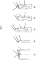
- Fig. 3
- shows various stages in a method of assembling a dispensing system in accordance with the present invention.
- The drawings and following description relate to embodiments of the various aspects of the present invention by way of example only.
-
Fig. 1 shows an example of a fluidmedium dispensing system 1 in accordance with the present invention. Thedispensing system 1 includes avalve cup 2, acontainer 3, and avalve 4. Typically, in use the inner region of thecontainer 3 is pressurized to a pressure greater than atmospheric pressure. When a fluid medium is stored within thecontainer 3 this pressure is typically around 7 bar although the pressure is not limited to this value and may take any desired value limited only by regional or governmental restrictions. Thevalve 4 is generally held in a fixed position by thevalve cup 2 such that when a force is applied to thevalve 4 by a user, thevalve 4 is actuated to an open position. In this position, the pressure difference within and without thecontainer 3 causes the fluid medium to be distributed from thecontainer 3 via thevalve 4. Thevalve 4 is not shown in any detail in the drawings as any suitable known valve can be used. - The
container 3 comprises aneck 5 defining anopening 6 in which thevalve cup 2 is inserted. Theneck 5 also includes a rim 7 that preferably comprises anannular lip 8. - The
valve cup 2 comprises a first,inner part 9 that is located in theopening 6 of thecontainer 3 and a second,annular part 10 that covers the rim 7. Thefirst part 9 is adapted to retain thevalve 4 in a conventional manner and a plurality of strengtheningribs 11 may be provided located between the first andsecond parts first part 9 is an interference fit into theopening 6 of theneck 5 around the whole periphery of thefirst part 9. The outer diameter of thefirst part 9 and the diameter of theopening 6 are therefore predetermined in order to control the degree of force required to push-fit the first part of thevalve cup 2 into theopening 6. The outer diameter of theinner part 9 is between 0.05 mm and 0.15 mm inclusive, and in particular 0.10 mm, greater than the inner diameter of theopening 6 prior to pressing of thefirst part 9 into theopening 6 in order to create the interference fit. During assembly, as described below, thevalve cup 2 is pressed into theopening 6 of theneck 5 with a force that is between 343 and 442 N, that is with a force between approximately 35 and 45 kg force. In particular, the force is preferably around 392 N, that is about 40 kg force. At the same time thesecond part 10 of thevalve cup 2 is preferably snap-fitted over the rim 7 of theneck 5. To this end the second,annular part 10 of thevalve cup 2 is formed in an inverted U-shape in which the rim 7 of theneck 5 of thecontainer 3 locates. Advantageously, the U-shapedsecond part 10 comprises at least oneprotrusion 12 on a surface of anouter leg 13 of the U-shape that faces theneck 5 of the container. Theprotrusion 12 preferably takes the form of an annular bead that is adapted to frictionally engage theneck 5 and to snap-fit over the rim 7 by engagement over and around thelip 8. - In addition, the U-shaped
second part 10 comprises aninner leg 14 that lies contiguous with the inner surface of theneck 5 to a level below that of theouter leg 13 and the snap-fitment between theprotrusion 12 and the rim 7. Also, theinner leg 14 and theneck 5 are contiguous around the whole periphery of thefirst part 9 of thevalve cup 1 that is inserted into theneck 5. This is important because thecontainer 3 is sealed after pressurization, as is described below, by laser welding of thevalve cup 2 to thecontainer 3. During this process the contiguous parts of thevalve cup 2 and thecontainer 3 are fused to form amolten weld seam 15a and/or 15b. Theseam container 3 and the peripheral contact between thefirst part 9 of the valve cup and theneck 5 ensures that themolten weld seam neck 5 that is closed by thefirst part 9 of thevalve cup 2. - To enable laser welding to take place, the contiguous parts of the
valve cup 2 and the neck must be made of plastics material as the welding process generates heat that causes these parts to fuse together to form themolten weld seam arrow 17 inFig. 1 , is directed at the contiguous parts of thevalve cup 2 and thecontainer 3. In some embodiments, themolten weld seam 15a is located between theinner part 9 of thevalve cup 2 that is pressed into theopening 6 of thecontainer 3 and theneck 5 of the container below the rim 7. In other embodiments, themolten weld seam 15b is located between the rim 7 of theneck 5 of thecontainer 3 and the U-shaped, outerannular part 13 of thevalve cup 2. In yet other embodiments two molten weld seams 15a and 15b are formed percontainer 3 in both of the aforesaid locations. The laser beam or beams are focused on the relevant interface or interfaces between theneck 5 and thevalve cup 2. Hence, the plastics material of theneck 5 of thecontainer 3 is preferably laser-transparent whereas the plastics material of thevalve cup 2 is preferably laser-absorbing. - While that part of the
valve cup 2 adjacent the relevantmolten weld seam valve cup 2 is comprised of one or more laser-absorbing polymers. In addition, it has been found that fully crystallized plastics materials tends to lose their shape during laser welding owing to the high temperatures reached. This does not occur with semi-crystalline polymers. Advantageously, therefore, preferably the whole of thevalve cup 2 is comprised of one or more laser-absorbing semi-crystalline polymers. - Semi-crystalline polyesters have a greater degree of crystallinity when compared to more amorphous polyesters and they do not deform when exposed to temperatures greater than 50°C. Crystallized PET (CPET), PBT, PEN, and PEN/PET copolymers are or can be semi-crystalline polyesters. These materials are particularly advantageous for their other properties in packaging and not just their rigidity at elevated temperatures. However, any polyester that can be semi-crystalline and does not deform to a suitable degree at large temperatures may also be used as the semi-crystalline material. Moreover, any blend of CPET, PBT, PEN, and PEN/PET may be used. Such polymers are made laser-absorbing by the use of one or more appropriate additives such as carbon black or other pigments and fills as will be known to those skilled in the art.
- Preferably, therefore, the plastics material of the
valve cup 2 is selected from a group consisting of semi-crystallized PET, PBT, PEN, PEN/PET copolymers, POM, acrylonitrile, polypropylene, or a blend of any of the foregoing. - The
plastics neck 5 of thecontainer 3 is also preferably selected from a group consisting of crystallized PET, PBT, PEN, PEN/PET copolymers, POM, acrylonitrile, polypropylene, or a blend of any of the foregoing. Advantageously, the whole of thecontainer 3 is comprised of a laser-transparent plastics material. It should be appreciated that thecontainer 3 may still be coloured and even opaque if special non-absorbing colorants are used, which are again known to those skilled in the art. The fluidmedium dispensing systems 1 that are sealed using laser welding in accordance with the invention fulfil European safety standards by providing appropriate sealing performance at temperatures greater than 50°C whilst still enabling both thecontainer 3 and thevalve cup 2 to be made of plastics materials. - In accordance with the present invention an example of a method of assembling a dispensing system in accordance with the present invention using a
valve cup 2 andcontainer 3 as described above is now given with particular reference toFig. 3 . - In this method a
bag 16 is attached to thevalve 4. Initially, thevalve 3 is coupled to thevalve cup 2 in known manner. In general any method or coupling may be used dependent on the structure of thevalve 4 and thevalve cup 2. Thebag 16 is then connected to thevalve 4 as shown inFig. 3(a) . More specifically, an opening of thebag 16 is attached to a lower part of thevalve 4 such that thevalve 4 is in fluid communication with the interior of thebag 16 when actuated. Thevalve 4 may be provided with any means for facilitating this coupling. Thebag 16 may be secured by any suitable means such as adhesive, welding, or clamping. The combination ofbag 16 andvalve 4 in a fixed arrangement is generally referred to as a 'bag on valve' (BoV). Thebag 16 is preferably liquid, gas, or fluid impermeable. - Once the
bag 16 is securely attached to thevalve 4, thebag 16 may be folded to reduce the footprint thereof. As shown inFig. 3(b) , thebag 16 may be folded in such a way that the footprint is less than the diameter of thevalve cup 2. Preferably, the footprint is less than the diameter of theopening 6 of acontainer 3 to which thevalve cup 2 is to be assembled such that the BoV may be inserted into theopening 6. The folded BoV is then inserted directly into thecontainer 3, as is shown inFig.3(c) . In this step, the BoV is inserted through theopening 6 of thecontainer 3 while being maintained in the folded state to improve the ease of insertion. - Once partially inserted, the inner region of the
container 3 may be charged with gas, preferably a propellant gas. Suitable propellants are known in the art and are not discussed further herein. The method used is preferably undercup gassing, which essentially means that the propellant is passed under thevalve cup 2 and into the region between thebag 16 and the inner volume of thecontainer 3. In the present invention, the inner volume of thecontainer 3 may be pressurized to a pressure up to 3 bar, preferably between 1.5 and 2.5 bar inclusive. - Once pressurization of the
container 3 is complete, thefirst part 9 of thevalve cup 2 is pressed into thecontainer 3. As described above, thevalve cup 2 is pressed into theopening 6 of theneck 5 with a force that is between 343 and 442 N, preferably the force is around 392 N. At the same time thesecond part 10 of thevalve cup 2 is snap-fitted over the rim 7 of theneck 5. This ensures a stable connection between thevalve cup 2 and thecontainer 3 that will withstand the pressure exerted on thevalve cup 2 by the pressurized contents of thecontainer 3. As described above, the interference fit between thevalve cup 2 and theneck 5 of thecontainer 3 is created by manufacturing theinner part 9 of thevalve cup 2 so that it has an outer diameter which is between 0.05 mm and 0.15 mm inclusive, and in particular 0.10 mm, greater than the inner diameter of theopening 6. - The
dispensing system 1 is then sealed by fusing the plastics materials of thevalve cup 2 and thecontainer 3 together to form themolten weld seam 15a and/or 15b by laser welding. During this process one or morefocussed laser beams 17 are directed at the interface between thevalve cup 2 and theneck 5 of the container as described above and shown in greater detail inFig. 1 . Thecontainer 3 is preferably rotated relative to the beam or beams 17 so that themolten weld seam 15a and/or 15b is formed around the totality of theopening 6 in theneck 5 around the whole periphery of thefirst part 9 of thevalve cup 2. - Once the laser welding has taken place, the
dispensing system 1 is filled with the fluid medium to be dispensed. This is usually passed through thevalve 4 into thebag 16 by appropriate channels provided for this purpose that are thereafter close. The pressure in thecontainer 3 increases as thebag 16 fills with the fluid medium. Preferably, the pressure increases to around 6 to 8 bar, preferably 6.5 to 7.5 bar. This increase in pressure aids in dispensing the fluid medium when the valve 50 is actuated by a user. - Additional assembly steps are also possible, such as adding a
protective overcap 18 to cover the exposed part of thevalve 4, as shown inFig. 3(e) . A shrink-wrap covering (not shown) may also be applied to the exterior of thecontainer 3. - While the method above describes a method of assembling a BOV dispensing system, it will be appreciated that other methods in accordance with the present invention that do not include a
bag 16 are possible. In dispensing systems wherein abag 16 is not used, the internal volume of thecontainer 3 is charged with the fluid medium to be dispensed prior to pressing of thevalve cup 2 into the container. A propellant is then added to the contents of the container after formation of the molten weld seam via channels in thevalve 4 in conventional fashion.
Claims (15)
- A fluid medium dispensing system (1) comprising:a container (3) for storing a fluid medium under pressure, the container (3) comprising a neck (5) defining an opening (6);a valve (4); anda valve cup (2) adapted to support the valve (4) and close the opening (6) of the container (3), contiguous portions of the valve cup (2) and the neck (5) being comprised of plastics materials,wherein the valve cup (2) comprises an inner part (9) that is inserted in the neck (5) by pressing and located in the opening (6) of the container (3) andwherein the valve cup (2) is an interference fit in the neck (5) of the container (3) with contact between said plastics materials of the valve cup (2) and of the neck (5) around a whole periphery of the inner part of the valve cup (2) andwherein an outer diameter of the inner part (9) of the valve cup (2) prior to pressing of the valve cup (2) into the opening (6) of the container (3) is between 0.05 mm and 0.15 mm inclusive greater than the inner diameter of the opening (6) in order to create the interference fit andwherein said plastics materials of the valve cup (2) and the neck (5) have been fused to form a molten weld seam (15a, 15b) by laser welding thereby sealing the container (3).
- A fluid medium dispensing system (1) as claimed in Claim 1, the plastics material of the neck (5) of the container (3) is laser-transparent and the plastics material of the valve cup (2) is laser-absorbing.
- A fluid medium dispensing system (1) as claimed in Claim 1 or 2, wherein the outer diameter of the inner part (9) of the valve cup (2) prior to pressing of the valve cup (2) into the opening (6) of the container (3) is 0.10 mm greater than the inner diameter of the opening (6).
- A fluid medium dispensing system (1) as claimed in any of Claims 1 to 3, wherein the molten weld seam (15a) is located between the inner part (9) of the valve cup (2) that is pressed into the opening (6) of the container (3) and the neck (5) of the container (3).
- A fluid medium dispensing system (1) as claimed in any of Claims 1 to 4, wherein the valve cup (2) comprises an outer, annular part (13) that defines a U-shape in which a rim (7) of the neck (5) of the container (3) is located.
- A fluid medium dispensing system (1) as claimed in Claim 5, wherein the molten weld seam (15a) or an additional molten weld seam (15b) is located between the rim (7) of the neck (5) of the container (3) and the U-shaped, outer annular part (13) of the valve cup (2).
- A fluid medium dispensing system (1) as claimed in Claim 4 or Claim 5, wherein the U-shaped, annular part (13) comprises a leg (14) that is contiguous with an inner surface of the neck (5).
- A method of assembling a dispensing system (1) for dispensing a fluid medium stored under pressure, the method including:providing a valve cup (2) with at least a peripheral portion that is comprised of a plastics material, the valve cup (2) including a valve (4);providing a container (3), the container (3) being suitable for storing the fluid medium under pressure and comprising a neck (5) that is comprised of a plastics material and that defines an opening (6);positioning the valve cup (2) at the opening (6) of the container (3);charging an internal volume of the container (3);pressing the valve cup (2) into the neck (5) of the container (3) with a force between 343 and 442 N,wherein valve cup (2) comprises an inner part (9) that is located in the opening (6) of the container (3) and wherein an outer diameter of the inner part (9) prior to pressing of the valve cup (2) into the opening (6) of the container (3) is between 0.05 mm and 0.15 mm inclusive greater than an inner diameter of the opening (6) in order to create an interference fit between the valve cup (2) and the neck (5) of the container (3); andfusing said plastics materials of the valve cup (2) and the neck (5) together to form a molten weld seam (15a, 15b) by laser welding thereby sealing the container (3).
- A method as claimed in Claim 8, wherein prior to charging the internal volume of the container (3), the method comprises the additional steps of providing a bag (16), attaching the valve (4) to an opening of the bag (16), fluidly sealing the bag (16) to the valve (4) and inserting the bag (16) into the container (3).
- A method as claimed in Claim 9, wherein the internal volume of the container (3) is pressurized with a propellant and the bag (16) is filled with a fluid medium to be dispensed after formation of the molten weld seam (15a, 15b).
- A method as claimed in Claim 10, wherein the internal volume of the container (3) between an inside wall of the container (3) and an outside surface of the bag (16) is pressurized at up to 13 bar.
- A method as claimed in Claim 8, wherein the internal volume of the container (3) is charged with a fluid medium to be dispensed and a propellant is added to the fluid medium contained in the container (3) after formation of the molten weld seam (15a, 15b).
- A method as claimed in Claim 8, wherein the valve cup (2) is pressed into the neck (5) of the container (3) with a force around 392 N.
- A method as claimed in any of Claims 8 to 13, wherein the container (3) is comprised of a laser-transparent plastics material.
- A method as claimed in Claim 14, wherein the laser-transparent plastics material is selected from a group consisting of: crystallized PET, PBT, PEN, PEN/PET copolymers, POM, acrylonitrile, polypropylene, or a blend of any of the foregoing.
Applications Claiming Priority (1)
| Application Number | Priority Date | Filing Date | Title |
|---|---|---|---|
| PCT/EP2017/050898 WO2018133925A1 (en) | 2017-01-17 | 2017-01-17 | Fluid medium dispensing system and a method of assembling a dispensing system for a fluid medium |
Publications (2)
| Publication Number | Publication Date |
|---|---|
| EP3571138A1 EP3571138A1 (en) | 2019-11-27 |
| EP3571138B1 true EP3571138B1 (en) | 2022-04-13 |
Family
ID=57890789
Family Applications (1)
| Application Number | Title | Priority Date | Filing Date |
|---|---|---|---|
| EP17701441.2A Active EP3571138B1 (en) | 2017-01-17 | 2017-01-17 | Fluid medium dispensing system and a method of assembling a dispensing system for a fluid medium |
Country Status (5)
| Country | Link |
|---|---|
| US (1) | US10934080B2 (en) |
| EP (1) | EP3571138B1 (en) |
| AR (1) | AR110175A1 (en) |
| RU (1) | RU2733009C1 (en) |
| WO (1) | WO2018133925A1 (en) |
Families Citing this family (5)
| Publication number | Priority date | Publication date | Assignee | Title |
|---|---|---|---|---|
| US10501258B2 (en) * | 2017-05-26 | 2019-12-10 | The Procter & Gamble Company | Aerosol dispenser having annular seals and aerosol container therefor |
| US10486892B1 (en) * | 2018-08-22 | 2019-11-26 | The Procter & Gamble Company | Packages and arrays of packages for plastic aerosol dispensers |
| US10781033B1 (en) * | 2019-10-29 | 2020-09-22 | APC Packaging, LLC | Reusable bottle package |
| WO2023280884A1 (en) | 2021-07-06 | 2023-01-12 | A.P.R.S. Bv | Fluid dispenser container and method for producing a fluid dispenser container |
| FR3131576B1 (en) * | 2022-01-06 | 2024-04-12 | Lindal France Sas | VALVE CUP FOR PRESSURE VESSEL |
Family Cites Families (39)
| Publication number | Priority date | Publication date | Assignee | Title |
|---|---|---|---|---|
| US2658714A (en) * | 1950-02-16 | 1953-11-10 | Allied Chem & Dye Corp | Dispenser valve assembly |
| US5007231A (en) * | 1985-08-16 | 1991-04-16 | Plm Ab | Container |
| JP2612758B2 (en) * | 1987-06-26 | 1997-05-21 | ヴエルデイング,ヴインフリート・ジヤン | Apparatus for controlling storage and discharge of products under pressure |
| US5219005A (en) * | 1990-02-15 | 1993-06-15 | Hans Stoffel | Method for readying a twin chamber container to be filled with a product |
| AU7601794A (en) * | 1993-09-03 | 1995-03-22 | Procter & Gamble Company, The | Improved tear-away canister lid |
| US6253941B1 (en) * | 1999-01-19 | 2001-07-03 | Crown Cork & Seal Technologies Corporation | Assembly for securing and sealing a dispenser to a flanged container |
| BRPI0311148B1 (en) * | 2002-05-21 | 2015-09-22 | Aptargroup Inc | improved aerosol dispenser, and process for filling the same |
| US7913877B2 (en) * | 2003-01-21 | 2011-03-29 | Aptargroup Inc. | Aerosol mounting cup for connection to a collapsible container |
| US7011236B2 (en) * | 2003-04-03 | 2006-03-14 | Rexam Beauty And Closure Inc. | Assembly for securing and sealing a dispenser including a decorative collar to a flanged container |
| US7124788B2 (en) * | 2003-07-10 | 2006-10-24 | Precision Valve Corporation | Means and method for filling bag-on-valve aerosol barrier packs |
| US20060006200A1 (en) * | 2004-07-12 | 2006-01-12 | L'oreal | Device for dispensing a product |
| ATE401259T1 (en) * | 2005-02-15 | 2008-08-15 | Goemar Lab Sa | DEVICE FOR DISPENSING FLUIDS, PARTICULARLY MEDICINAL FLUIDS UNDER PRESSURE |
| US20070241131A1 (en) * | 2006-04-17 | 2007-10-18 | The Procter & Gamble Company | Preferentially expandable/collapsable container and package therefor |
| US20070241132A1 (en) * | 2006-04-17 | 2007-10-18 | The Procter & Gamble Company | Pressurized package |
| FR2921642B1 (en) * | 2007-09-28 | 2011-07-15 | Power Container Corp | DEVICE FOR DISPENSING FLUID PRODUCT, METHOD OF MAKING SUCH DEVICE AND APPARATUS FOR IMPLEMENTING SUCH A METHOD |
| WO2009032762A2 (en) * | 2007-08-28 | 2009-03-12 | Meadwestvaco Calmar, Inc. | Plastic valves and methods of using the same |
| DE102007051982A1 (en) * | 2007-08-29 | 2009-03-05 | Seaquist Perfect Dispensing Gmbh | dispenser |
| BR112013002491B1 (en) * | 2010-12-02 | 2019-07-02 | Toyo Aerosol Industry Co., Ltd. | AEROSOL DEVICE |
| EP2657151B1 (en) * | 2010-12-22 | 2020-10-21 | Daizo Corporation | Valve assembly and aerosol container equipped with same, and aerosol product and process for production thereof |
| PT2739551T (en) * | 2011-08-01 | 2017-10-19 | Graham Packaging Co | Plastic aerosol container and method of manufacture |
| US9758294B2 (en) * | 2013-01-25 | 2017-09-12 | The Procter & Gamble Company | Components for aerosol dispenser and aerosol dispenser made therewith |
| DE102013107061A1 (en) * | 2013-07-04 | 2015-01-08 | Thomas Gmbh | aerosol container |
| US9132955B2 (en) * | 2013-10-23 | 2015-09-15 | The Procter & Gamble Company | Compressible valve for a pressurized container |
| US20160101925A1 (en) * | 2014-10-10 | 2016-04-14 | Walter Franz | Spray can |
| MX2017009734A (en) * | 2015-01-28 | 2018-04-10 | Airopack Tech Group B V | Pressure control system. |
| US10301104B2 (en) * | 2015-06-18 | 2019-05-28 | The Procter & Gamble Company | Piston aerosol dispenser |
| US20160377186A1 (en) * | 2015-06-25 | 2016-12-29 | The Gillette Company | Compressible valve and actuator for a pressurized container |
| KR20180037207A (en) * | 2015-08-04 | 2018-04-11 | 코스터 테크날러지 스페셜리 에스.피.에이. | Valve cups and containers for use in fluid medium dispensing systems |
| US20180222613A1 (en) * | 2015-08-04 | 2018-08-09 | Coster Technologie Speciali S.P.A. | Method for assembling a dispensing system for dispensing a fluid medium |
| WO2017021039A1 (en) | 2015-08-04 | 2017-02-09 | Coster Tecnologie Speciali S.P.A. | Method for assembling a dispensing system for dispensing a fluid medium |
| BR112018075470A2 (en) * | 2016-06-15 | 2019-03-19 | Coster Tecnologie Speciali Spa | fluid media dispensing system and method of mounting a dispensing system for dispensing a pressurized fluid medium |
| US10661974B2 (en) * | 2016-08-12 | 2020-05-26 | The Procter & Gamble Company | Internally fitted aerosol dispenser |
| CH713554A1 (en) * | 2017-03-09 | 2018-09-14 | Alpla Werke Alwin Lehner Gmbh & Co Kg | Method for establishing a connection between components made of plastic materials which are different from one another and containers with pouring attachment in relation thereto. |
| US10640284B2 (en) * | 2017-11-06 | 2020-05-05 | The Procter & Gamble Company | Aerosol dispenser with vented valve cup and valve cup therefor |
| EP3483084B1 (en) * | 2017-11-09 | 2020-05-27 | Coster Tecnologie Speciali S.p.A. | Container of a fluid substance and a transport system therefor |
| EP3774593A1 (en) * | 2018-04-05 | 2021-02-17 | Plastipak Packaging, Inc. | Plastic preform and container with modified neck |
| MY193870A (en) * | 2018-05-31 | 2022-10-29 | Boon Leong Saw | A container for aerosol system |
| US10486892B1 (en) * | 2018-08-22 | 2019-11-26 | The Procter & Gamble Company | Packages and arrays of packages for plastic aerosol dispensers |
| US11267644B2 (en) * | 2018-11-08 | 2022-03-08 | The Procter And Gamble Company | Aerosol foam dispenser and methods for delivering a textured foam product |
-
2017
- 2017-01-17 RU RU2019123595A patent/RU2733009C1/en active
- 2017-01-17 WO PCT/EP2017/050898 patent/WO2018133925A1/en unknown
- 2017-01-17 EP EP17701441.2A patent/EP3571138B1/en active Active
- 2017-01-17 US US16/469,813 patent/US10934080B2/en active Active
- 2017-11-17 AR ARP170103209A patent/AR110175A1/en unknown
Non-Patent Citations (1)
| Title |
|---|
| None * |
Also Published As
| Publication number | Publication date |
|---|---|
| RU2733009C1 (en) | 2020-09-28 |
| WO2018133925A1 (en) | 2018-07-26 |
| EP3571138A1 (en) | 2019-11-27 |
| US10934080B2 (en) | 2021-03-02 |
| AR110175A1 (en) | 2019-03-06 |
| US20200087053A1 (en) | 2020-03-19 |
Similar Documents
| Publication | Publication Date | Title |
|---|---|---|
| EP3571138B1 (en) | Fluid medium dispensing system and a method of assembling a dispensing system for a fluid medium | |
| KR102396798B1 (en) | Mixing/closure device for a container and method for dispensing a medium from a closure device | |
| EP2247511B1 (en) | Assembly of a container and a closure | |
| US6651847B2 (en) | Double pressurized container for charging undercup and double pressurized products using the container | |
| US9969543B2 (en) | Plastic aerosol container | |
| US9475636B2 (en) | Valve assembly and aerosol container equipped with the same, and aerosol product and process for production thereof | |
| EP3683169B1 (en) | Method for assembling a dispensing system for dispensing a fluid medium | |
| US20070125809A1 (en) | Pressure control device | |
| JP4899923B2 (en) | Method of welding member having layer made of thermoplastic resin and thermoplastic resin container with lid | |
| CN110386364B (en) | Crystalline plastic valve for aerosol dispenser and housing therefor | |
| JP2015500778A (en) | Plastic container for pressure-packing filled products and method of manufacturing the same | |
| WO2017021038A1 (en) | Valve cups and containers for use in fluid medium dispensing systems | |
| US6116500A (en) | Composite container | |
| EP3331776B1 (en) | Valve cups and containers for use in fluid medium dispensing systems | |
| US5224630A (en) | Pressurized container having double walls and safety venting feature | |
| JP2005104537A (en) | Tube container, and composite container using the tube container | |
| JP3764226B2 (en) | Pressure vessel lid structure |
Legal Events
| Date | Code | Title | Description |
|---|---|---|---|
| STAA | Information on the status of an ep patent application or granted ep patent |
Free format text: STATUS: UNKNOWN |
|
| STAA | Information on the status of an ep patent application or granted ep patent |
Free format text: STATUS: THE INTERNATIONAL PUBLICATION HAS BEEN MADE |
|
| PUAI | Public reference made under article 153(3) epc to a published international application that has entered the european phase |
Free format text: ORIGINAL CODE: 0009012 |
|
| STAA | Information on the status of an ep patent application or granted ep patent |
Free format text: STATUS: REQUEST FOR EXAMINATION WAS MADE |
|
| 17P | Request for examination filed |
Effective date: 20190523 |
|
| AK | Designated contracting states |
Kind code of ref document: A1 Designated state(s): AL AT BE BG CH CY CZ DE DK EE ES FI FR GB GR HR HU IE IS IT LI LT LU LV MC MK MT NL NO PL PT RO RS SE SI SK SM TR |
|
| AX | Request for extension of the european patent |
Extension state: BA ME |
|
| DAV | Request for validation of the european patent (deleted) | ||
| DAX | Request for extension of the european patent (deleted) | ||
| STAA | Information on the status of an ep patent application or granted ep patent |
Free format text: STATUS: EXAMINATION IS IN PROGRESS |
|
| STAA | Information on the status of an ep patent application or granted ep patent |
Free format text: STATUS: EXAMINATION IS IN PROGRESS |
|
| 17Q | First examination report despatched |
Effective date: 20201009 |
|
| GRAP | Despatch of communication of intention to grant a patent |
Free format text: ORIGINAL CODE: EPIDOSNIGR1 |
|
| STAA | Information on the status of an ep patent application or granted ep patent |
Free format text: STATUS: GRANT OF PATENT IS INTENDED |
|
| INTG | Intention to grant announced |
Effective date: 20211025 |
|
| GRAS | Grant fee paid |
Free format text: ORIGINAL CODE: EPIDOSNIGR3 |
|
| GRAA | (expected) grant |
Free format text: ORIGINAL CODE: 0009210 |
|
| STAA | Information on the status of an ep patent application or granted ep patent |
Free format text: STATUS: THE PATENT HAS BEEN GRANTED |
|
| AK | Designated contracting states |
Kind code of ref document: B1 Designated state(s): AL AT BE BG CH CY CZ DE DK EE ES FI FR GB GR HR HU IE IS IT LI LT LU LV MC MK MT NL NO PL PT RO RS SE SI SK SM TR |
|
| REG | Reference to a national code |
Ref country code: GB Ref legal event code: FG4D |
|
| REG | Reference to a national code |
Ref country code: CH Ref legal event code: EP |
|
| REG | Reference to a national code |
Ref country code: DE Ref legal event code: R096 Ref document number: 602017055859 Country of ref document: DE |
|
| REG | Reference to a national code |
Ref country code: IE Ref legal event code: FG4D |
|
| REG | Reference to a national code |
Ref country code: AT Ref legal event code: REF Ref document number: 1483261 Country of ref document: AT Kind code of ref document: T Effective date: 20220515 |
|
| REG | Reference to a national code |
Ref country code: LT Ref legal event code: MG9D |
|
| REG | Reference to a national code |
Ref country code: NL Ref legal event code: MP Effective date: 20220413 |
|
| REG | Reference to a national code |
Ref country code: AT Ref legal event code: MK05 Ref document number: 1483261 Country of ref document: AT Kind code of ref document: T Effective date: 20220413 |
|
| PG25 | Lapsed in a contracting state [announced via postgrant information from national office to epo] |
Ref country code: NL Free format text: LAPSE BECAUSE OF FAILURE TO SUBMIT A TRANSLATION OF THE DESCRIPTION OR TO PAY THE FEE WITHIN THE PRESCRIBED TIME-LIMIT Effective date: 20220413 |
|
| PG25 | Lapsed in a contracting state [announced via postgrant information from national office to epo] |
Ref country code: SE Free format text: LAPSE BECAUSE OF FAILURE TO SUBMIT A TRANSLATION OF THE DESCRIPTION OR TO PAY THE FEE WITHIN THE PRESCRIBED TIME-LIMIT Effective date: 20220413 Ref country code: PT Free format text: LAPSE BECAUSE OF FAILURE TO SUBMIT A TRANSLATION OF THE DESCRIPTION OR TO PAY THE FEE WITHIN THE PRESCRIBED TIME-LIMIT Effective date: 20220816 Ref country code: NO Free format text: LAPSE BECAUSE OF FAILURE TO SUBMIT A TRANSLATION OF THE DESCRIPTION OR TO PAY THE FEE WITHIN THE PRESCRIBED TIME-LIMIT Effective date: 20220713 Ref country code: LT Free format text: LAPSE BECAUSE OF FAILURE TO SUBMIT A TRANSLATION OF THE DESCRIPTION OR TO PAY THE FEE WITHIN THE PRESCRIBED TIME-LIMIT Effective date: 20220413 Ref country code: HR Free format text: LAPSE BECAUSE OF FAILURE TO SUBMIT A TRANSLATION OF THE DESCRIPTION OR TO PAY THE FEE WITHIN THE PRESCRIBED TIME-LIMIT Effective date: 20220413 Ref country code: GR Free format text: LAPSE BECAUSE OF FAILURE TO SUBMIT A TRANSLATION OF THE DESCRIPTION OR TO PAY THE FEE WITHIN THE PRESCRIBED TIME-LIMIT Effective date: 20220714 Ref country code: FI Free format text: LAPSE BECAUSE OF FAILURE TO SUBMIT A TRANSLATION OF THE DESCRIPTION OR TO PAY THE FEE WITHIN THE PRESCRIBED TIME-LIMIT Effective date: 20220413 Ref country code: ES Free format text: LAPSE BECAUSE OF FAILURE TO SUBMIT A TRANSLATION OF THE DESCRIPTION OR TO PAY THE FEE WITHIN THE PRESCRIBED TIME-LIMIT Effective date: 20220413 Ref country code: BG Free format text: LAPSE BECAUSE OF FAILURE TO SUBMIT A TRANSLATION OF THE DESCRIPTION OR TO PAY THE FEE WITHIN THE PRESCRIBED TIME-LIMIT Effective date: 20220713 Ref country code: AT Free format text: LAPSE BECAUSE OF FAILURE TO SUBMIT A TRANSLATION OF THE DESCRIPTION OR TO PAY THE FEE WITHIN THE PRESCRIBED TIME-LIMIT Effective date: 20220413 |
|
| PG25 | Lapsed in a contracting state [announced via postgrant information from national office to epo] |
Ref country code: RS Free format text: LAPSE BECAUSE OF FAILURE TO SUBMIT A TRANSLATION OF THE DESCRIPTION OR TO PAY THE FEE WITHIN THE PRESCRIBED TIME-LIMIT Effective date: 20220413 Ref country code: PL Free format text: LAPSE BECAUSE OF FAILURE TO SUBMIT A TRANSLATION OF THE DESCRIPTION OR TO PAY THE FEE WITHIN THE PRESCRIBED TIME-LIMIT Effective date: 20220413 Ref country code: LV Free format text: LAPSE BECAUSE OF FAILURE TO SUBMIT A TRANSLATION OF THE DESCRIPTION OR TO PAY THE FEE WITHIN THE PRESCRIBED TIME-LIMIT Effective date: 20220413 Ref country code: IS Free format text: LAPSE BECAUSE OF FAILURE TO SUBMIT A TRANSLATION OF THE DESCRIPTION OR TO PAY THE FEE WITHIN THE PRESCRIBED TIME-LIMIT Effective date: 20220813 |
|
| REG | Reference to a national code |
Ref country code: DE Ref legal event code: R097 Ref document number: 602017055859 Country of ref document: DE |
|
| PG25 | Lapsed in a contracting state [announced via postgrant information from national office to epo] |
Ref country code: SM Free format text: LAPSE BECAUSE OF FAILURE TO SUBMIT A TRANSLATION OF THE DESCRIPTION OR TO PAY THE FEE WITHIN THE PRESCRIBED TIME-LIMIT Effective date: 20220413 Ref country code: SK Free format text: LAPSE BECAUSE OF FAILURE TO SUBMIT A TRANSLATION OF THE DESCRIPTION OR TO PAY THE FEE WITHIN THE PRESCRIBED TIME-LIMIT Effective date: 20220413 Ref country code: RO Free format text: LAPSE BECAUSE OF FAILURE TO SUBMIT A TRANSLATION OF THE DESCRIPTION OR TO PAY THE FEE WITHIN THE PRESCRIBED TIME-LIMIT Effective date: 20220413 Ref country code: EE Free format text: LAPSE BECAUSE OF FAILURE TO SUBMIT A TRANSLATION OF THE DESCRIPTION OR TO PAY THE FEE WITHIN THE PRESCRIBED TIME-LIMIT Effective date: 20220413 Ref country code: DK Free format text: LAPSE BECAUSE OF FAILURE TO SUBMIT A TRANSLATION OF THE DESCRIPTION OR TO PAY THE FEE WITHIN THE PRESCRIBED TIME-LIMIT Effective date: 20220413 Ref country code: CZ Free format text: LAPSE BECAUSE OF FAILURE TO SUBMIT A TRANSLATION OF THE DESCRIPTION OR TO PAY THE FEE WITHIN THE PRESCRIBED TIME-LIMIT Effective date: 20220413 |
|
| PLBE | No opposition filed within time limit |
Free format text: ORIGINAL CODE: 0009261 |
|
| STAA | Information on the status of an ep patent application or granted ep patent |
Free format text: STATUS: NO OPPOSITION FILED WITHIN TIME LIMIT |
|
| 26N | No opposition filed |
Effective date: 20230116 |
|
| PG25 | Lapsed in a contracting state [announced via postgrant information from national office to epo] |
Ref country code: AL Free format text: LAPSE BECAUSE OF FAILURE TO SUBMIT A TRANSLATION OF THE DESCRIPTION OR TO PAY THE FEE WITHIN THE PRESCRIBED TIME-LIMIT Effective date: 20220413 |
|
| PGFP | Annual fee paid to national office [announced via postgrant information from national office to epo] |
Ref country code: FR Payment date: 20230124 Year of fee payment: 7 |
|
| PG25 | Lapsed in a contracting state [announced via postgrant information from national office to epo] |
Ref country code: SI Free format text: LAPSE BECAUSE OF FAILURE TO SUBMIT A TRANSLATION OF THE DESCRIPTION OR TO PAY THE FEE WITHIN THE PRESCRIBED TIME-LIMIT Effective date: 20220413 |
|
| PGFP | Annual fee paid to national office [announced via postgrant information from national office to epo] |
Ref country code: IT Payment date: 20230120 Year of fee payment: 7 Ref country code: DE Payment date: 20230130 Year of fee payment: 7 |
|
| P01 | Opt-out of the competence of the unified patent court (upc) registered |
Effective date: 20230601 |
|
| REG | Reference to a national code |
Ref country code: CH Ref legal event code: PL |
|
| GBPC | Gb: european patent ceased through non-payment of renewal fee |
Effective date: 20230117 |
|
| PG25 | Lapsed in a contracting state [announced via postgrant information from national office to epo] |
Ref country code: LU Free format text: LAPSE BECAUSE OF NON-PAYMENT OF DUE FEES Effective date: 20230117 |
|
| REG | Reference to a national code |
Ref country code: BE Ref legal event code: MM Effective date: 20230131 |
|
| PG25 | Lapsed in a contracting state [announced via postgrant information from national office to epo] |
Ref country code: LI Free format text: LAPSE BECAUSE OF NON-PAYMENT OF DUE FEES Effective date: 20230131 Ref country code: GB Free format text: LAPSE BECAUSE OF NON-PAYMENT OF DUE FEES Effective date: 20230117 Ref country code: CH Free format text: LAPSE BECAUSE OF NON-PAYMENT OF DUE FEES Effective date: 20230131 |
|
| PG25 | Lapsed in a contracting state [announced via postgrant information from national office to epo] |
Ref country code: BE Free format text: LAPSE BECAUSE OF NON-PAYMENT OF DUE FEES Effective date: 20230131 |
|
| PG25 | Lapsed in a contracting state [announced via postgrant information from national office to epo] |
Ref country code: IE Free format text: LAPSE BECAUSE OF NON-PAYMENT OF DUE FEES Effective date: 20230117 |