EP3570560A1 - Broadband ultrathin sound wave diffusion structure - Google Patents
Broadband ultrathin sound wave diffusion structure Download PDFInfo
- Publication number
- EP3570560A1 EP3570560A1 EP17907955.3A EP17907955A EP3570560A1 EP 3570560 A1 EP3570560 A1 EP 3570560A1 EP 17907955 A EP17907955 A EP 17907955A EP 3570560 A1 EP3570560 A1 EP 3570560A1
- Authority
- EP
- European Patent Office
- Prior art keywords
- acoustic wave
- section
- acoustic
- wave propagation
- focused
- Prior art date
- Legal status (The legal status is an assumption and is not a legal conclusion. Google has not performed a legal analysis and makes no representation as to the accuracy of the status listed.)
- Granted
Links
Images




Classifications
-
- G—PHYSICS
- G10—MUSICAL INSTRUMENTS; ACOUSTICS
- G10K—SOUND-PRODUCING DEVICES; METHODS OR DEVICES FOR PROTECTING AGAINST, OR FOR DAMPING, NOISE OR OTHER ACOUSTIC WAVES IN GENERAL; ACOUSTICS NOT OTHERWISE PROVIDED FOR
- G10K11/00—Methods or devices for transmitting, conducting or directing sound in general; Methods or devices for protecting against, or for damping, noise or other acoustic waves in general
- G10K11/18—Methods or devices for transmitting, conducting or directing sound
-
- G—PHYSICS
- G10—MUSICAL INSTRUMENTS; ACOUSTICS
- G10K—SOUND-PRODUCING DEVICES; METHODS OR DEVICES FOR PROTECTING AGAINST, OR FOR DAMPING, NOISE OR OTHER ACOUSTIC WAVES IN GENERAL; ACOUSTICS NOT OTHERWISE PROVIDED FOR
- G10K11/00—Methods or devices for transmitting, conducting or directing sound in general; Methods or devices for protecting against, or for damping, noise or other acoustic waves in general
- G10K11/16—Methods or devices for protecting against, or for damping, noise or other acoustic waves in general
- G10K11/162—Selection of materials
-
- G—PHYSICS
- G10—MUSICAL INSTRUMENTS; ACOUSTICS
- G10K—SOUND-PRODUCING DEVICES; METHODS OR DEVICES FOR PROTECTING AGAINST, OR FOR DAMPING, NOISE OR OTHER ACOUSTIC WAVES IN GENERAL; ACOUSTICS NOT OTHERWISE PROVIDED FOR
- G10K11/00—Methods or devices for transmitting, conducting or directing sound in general; Methods or devices for protecting against, or for damping, noise or other acoustic waves in general
- G10K11/18—Methods or devices for transmitting, conducting or directing sound
- G10K11/20—Reflecting arrangements
-
- H—ELECTRICITY
- H04—ELECTRIC COMMUNICATION TECHNIQUE
- H04R—LOUDSPEAKERS, MICROPHONES, GRAMOPHONE PICK-UPS OR LIKE ACOUSTIC ELECTROMECHANICAL TRANSDUCERS; ELECTRIC HEARING AIDS; PUBLIC ADDRESS SYSTEMS
- H04R1/00—Details of transducers, loudspeakers or microphones
- H04R1/20—Arrangements for obtaining desired frequency or directional characteristics
- H04R1/22—Arrangements for obtaining desired frequency or directional characteristics for obtaining desired frequency characteristic only
- H04R1/28—Transducer mountings or enclosures modified by provision of mechanical or acoustic impedances, e.g. resonator, damping means
- H04R1/2807—Enclosures comprising vibrating or resonating arrangements
- H04R1/2853—Enclosures comprising vibrating or resonating arrangements using an acoustic labyrinth or a transmission line
- H04R1/2857—Enclosures comprising vibrating or resonating arrangements using an acoustic labyrinth or a transmission line for loudspeaker transducers
Definitions
- the present invention belongs to the technical field of sound engineering, and relates to a broadband ultrathin acoustic wave diffusion structure.
- Schroeder diffuser Since Schroeder diffuser came out in 1970s, it has been widely used in the technical field of sound engineering, especially in music halls, theaters and other places with high sound requirements. Schroeder diffuser disperses sound energy by reflecting sound to different directions to prevent echoes and standing waves. In such an environment, the audience can feast their ears and experience an audio-visual feast.
- the thickness of Schroeder diffuser is in direct proportion to the length of sound waves.
- the present invention discloses a broadband ultrathin acoustic wave diffusion structure in combination with the transformation acoustics theory developed in recent years.
- the broadband ultrathin acoustic wave diffusion structure comprises a plurality of acoustic wave diffusion units.
- Each acoustic wave diffusion unit comprises at least one acoustic wave propagation section, and an acoustic wave focused section communicating with the acoustic wave propagation section is arranged according to needs.
- the acoustic wave focused section is formed by a through cavity filled with acoustic material.
- the through cavity has variable section, and isotropic or anisotropic acoustic material is filled in the variable-section cavity.
- the anisotropic acoustic material is formed by embedding membranes or string nets into the isotropic acoustic material.
- the acoustic wave propagation section is formed by a simply connected acoustic wave propagation passage with a close end.
- acoustic wave diffusion units In different acoustic wave diffusion units, simply connected acoustic wave propagation passages have different lengths. Some acoustic wave diffusion units have no acoustic wave focused section, and only comprise acoustic wave propagation sections. Some acoustic wave diffusion units comprise acoustic wave focused sections and acoustic wave propagation sections, and the through cavity of the acoustic wave focused section communicates with the simply connected acoustic wave propagation passages of the acoustic wave propagation sections.
- the simply connected acoustic wave propagation passage is closely arranged through the measures of circuity, bending, coiling or stacking in a monolayer or multilayer or spatial spiral structural form, and occupies part or whole of available space of the broadband ultrathin acoustic wave diffusion structure.
- the arrangement solutions of the simply connected acoustic wave propagation passage include:
- the membrane of the anisotropic acoustic material is a non-porous membrane or porous membrane, and is made of metal or nonmetallic, including cotton, fiber, silk, burlap, woolen cloth, mixture yarn and leather.
- the string net of the anisotropic acoustic material is made of metal or nonmetallic.
- the acoustic material is gas material, solid material or liquid material, including air, helium, gel, polyurethane, polyester, epoxy resin, foamed plastics, foamed metal, soft rubber, silicone rubber, butyl rubber, glass wool, glass fiber, felt, silk, cloth and micro-perforated panel.
- the broadband ultrathin acoustic wave diffusion structure disclosed by the present invention is greatly different in both the design principle and the structure itself.
- An external acoustic wave enters the broadband ultrathin acoustic wave diffusion structure disclosed by the present invention.
- the acoustic wave is focused in the acoustic wave focused section.
- the focused acoustic wave enters the acoustic wave propagation section, and propagates and reflects in the simply connected acoustic wave propagation passage.
- the simply connected acoustic wave propagation passage can be designed into a narrow and long passage according to needs through the close arrangement measures of circuity, bending, coiling and stacking.
- the maximum length of the simply connected acoustic wave propagation passage may be dozens or even hundreds of times of the thickness of the acoustic wave diffusion structure, which can meet the diffusion requirements for low frequency acoustic waves to the maximum extent.
- 1 acoustic wave diffusion unit 1 acoustic wave diffusion unit; 2 acoustic wave focused section; 3 acoustic wave propagation section; 4 acoustic material filled in acoustic wave focused cavity; 5 membrane or string net embedded in acoustic material; 6 wall of acoustic wave focused cavity; 7 isolated wall between simply connected acoustic wave propagation passages belonging to different acoustic wave diffusion units; 8 simply connected acoustic wave propagation passage; 9 wall of simply connected acoustic wave propagation passage; 10 communication hole between adjacent layers of laminated simply connected acoustic wave propagation passages.
- the arrow in the figure indicates the direction of propagation of the acoustic wave, wherein a solid line with arrow indicates propagation of the acoustic wave in its own acoustic wave diffusion unit; and a dotted line with arrow indicates propagation of the acoustic wave from other acoustic wave diffusion units in the acoustic wave diffusion unit.
- a plurality of acoustic wave diffusion units are arranged along a body surface to form a broadband ultrathin acoustic wave diffusion structure, as shown in Figure and Figure 2 .
- Each acoustic wave diffusion unit 1 comprises at least one acoustic wave propagation section 3, and an acoustic wave focused section 2 communicating with the acoustic wave propagation section 3 is arranged according to needs.
- the acoustic wave focused section 2 is formed by a through cavity filled with acoustic material.
- the sectional diagram of the acoustic wave focused section 2 is shown in Figure 6 .
- the acoustic wave focused cavity is a variable-section cavity, and the end surface of the cavity is a hexagon.
- the acoustic material 4 is filled in the variable-section cavity, and multilayer membranes 5 are embedded at equal spacing in the variable-section cavity.
- the acoustic wave propagation section 3 is formed by a simply connected acoustic wave propagation passage 8 with a close end, and its monolayer schematic diagrams are shown in Figure 11 and Figure 12 .
- Different acoustic wave diffusion units 1 have different lengths of the simply connected acoustic wave propagation passages 8.
- the broadband ultrathin acoustic wave diffusion structure For the broadband ultrathin acoustic wave diffusion structure, first, external acoustic waves enter the acoustic wave focused section 2, and are focused by the variable-section cavity and the acoustic material filled therein. Then, the focused acoustic waves enter the acoustic wave propagation section 3, and propagate and reflect in the simply connected acoustic wave propagation passages 8.
- the maximum length of the simply connected acoustic wave propagation passage 8 may be dozens or even hundreds of times of the thickness of the broadband ultrathin acoustic wave diffusion structure.
- the present embodiment is substantially the same as embodiment 1, and is different from embodiment 1 in that: (1) the cavity end surface of the acoustic wave focused section, as shown in Figure 7 , is a quadrangle.
- the acoustic material 4 is filled in the variable-section cavity, and multilayer fibers 5 are embedded at equal spacing in the cavity.
- (2) The monolayer schematic diagrams of the simply connected acoustic wave propagation passage 8 of the acoustic wave propagation section 3 are shown in Figure 13 and Figure 14 .
- the present embodiment is substantially the same as embodiment 1, and is different from embodiment 1 in that: (1) the cavity end surface of the acoustic wave focused section, as shown in Figure 8 , is a circle. The acoustic material 4 is filled in the variable-section cavity, and multilayer silks 5 are embedded at different spacings in the cavity. (2) The monolayer schematic diagrams of the simply connected acoustic wave propagation passage 8 of the acoustic wave propagation section 3 are shown in Figure 15 and Figure 16 .
- the present embodiment is substantially the same as embodiment 1, and is different from embodiment 1 in that: the cavity end surface of the acoustic wave focused section, as shown in Figure 9 , is a pentagon.
- the acoustic material 4 is filled in the variable-section cavity, and multilayer metal string nets 5 are embedded at equal spacing in the cavity.
- the present embodiment is substantially the same as embodiment 1, and is different from embodiment 1 in that: the cavity end surface of the acoustic wave focused section, as shown in Figure 10 , is an oval.
- the acoustic material 4 is filled in the variable-section cavity, and multilayer cloth 5 are embedded at different spacings in the cavity.
Landscapes
- Physics & Mathematics (AREA)
- Engineering & Computer Science (AREA)
- Acoustics & Sound (AREA)
- Multimedia (AREA)
- Health & Medical Sciences (AREA)
- Otolaryngology (AREA)
- Signal Processing (AREA)
- Diaphragms For Electromechanical Transducers (AREA)
- Soundproofing, Sound Blocking, And Sound Damping (AREA)
Abstract
Description
- The present invention belongs to the technical field of sound engineering, and relates to a broadband ultrathin acoustic wave diffusion structure.
- Since Schroeder diffuser came out in 1970s, it has been widely used in the technical field of sound engineering, especially in music halls, theaters and other places with high sound requirements. Schroeder diffuser disperses sound energy by reflecting sound to different directions to prevent echoes and standing waves. In such an environment, the audience can feast their ears and experience an audio-visual feast. However, due to the limitation of the design principle, the thickness of Schroeder diffuser is in direct proportion to the length of sound waves. Thus, when diffusion requirements are put forward for low-frequency sound waves, the thickness size of Schroeder diffuser is inevitably very large. To solve this problem, the present invention discloses a broadband ultrathin acoustic wave diffusion structure in combination with the transformation acoustics theory developed in recent years.
- The present invention adopts the following technical solution:
The broadband ultrathin acoustic wave diffusion structure comprises a plurality of acoustic wave diffusion units. Each acoustic wave diffusion unit comprises at least one acoustic wave propagation section, and an acoustic wave focused section communicating with the acoustic wave propagation section is arranged according to needs. - The acoustic wave focused section is formed by a through cavity filled with acoustic material. The through cavity has variable section, and isotropic or anisotropic acoustic material is filled in the variable-section cavity. The anisotropic acoustic material is formed by embedding membranes or string nets into the isotropic acoustic material.
- The acoustic wave propagation section is formed by a simply connected acoustic wave propagation passage with a close end.
- In different acoustic wave diffusion units, simply connected acoustic wave propagation passages have different lengths. Some acoustic wave diffusion units have no acoustic wave focused section, and only comprise acoustic wave propagation sections. Some acoustic wave diffusion units comprise acoustic wave focused sections and acoustic wave propagation sections, and the through cavity of the acoustic wave focused section communicates with the simply connected acoustic wave propagation passages of the acoustic wave propagation sections. For the acoustic wave diffusion unit comprising the acoustic wave focused section and the acoustic wave propagation section, the simply connected acoustic wave propagation passage is closely arranged through the measures of circuity, bending, coiling or stacking in a monolayer or multilayer or spatial spiral structural form, and occupies part or whole of available space of the broadband ultrathin acoustic wave diffusion structure.
- For the acoustic wave diffusion unit comprising the acoustic wave focused section and the acoustic wave propagation section, the arrangement solutions of the simply connected acoustic wave propagation passage include:
- (1) the simply connected acoustic wave propagation passage is closely arranged inside its own acoustic wave diffusion unit through the measures of circuity, bending, coiling or stacking in a monolayer or multilayer or spatial spiral structural form, and occupies part or whole of available space outside the acoustic wave focused section; and
- (2) the simply connected acoustic wave propagation passage is closely arranged inside the broadband ultrathin acoustic wave diffusion structure through the measures of circuity, bending, coiling or stacking in a monolayer or multilayer or spatial spiral structural form, occupies the whole of available space inside its own acoustic wave diffusion unit and also extends to other acoustic wave diffusion units to occupy the remaining available space inside other acoustic wave diffusion units, especially occupy the remaining space of the acoustic wave diffusion units with short simply connected acoustic wave propagation passages.
- The membrane of the anisotropic acoustic material is a non-porous membrane or porous membrane, and is made of metal or nonmetallic, including cotton, fiber, silk, burlap, woolen cloth, mixture yarn and leather. The string net of the anisotropic acoustic material is made of metal or nonmetallic. The acoustic material is gas material, solid material or liquid material, including air, helium, gel, polyurethane, polyester, epoxy resin, foamed plastics, foamed metal, soft rubber, silicone rubber, butyl rubber, glass wool, glass fiber, felt, silk, cloth and micro-perforated panel.
- Compared with a traditional Schroeder diffuser, the broadband ultrathin acoustic wave diffusion structure disclosed by the present invention is greatly different in both the design principle and the structure itself. An external acoustic wave enters the broadband ultrathin acoustic wave diffusion structure disclosed by the present invention. First, the acoustic wave is focused in the acoustic wave focused section. Then, the focused acoustic wave enters the acoustic wave propagation section, and propagates and reflects in the simply connected acoustic wave propagation passage. The simply connected acoustic wave propagation passage can be designed into a narrow and long passage according to needs through the close arrangement measures of circuity, bending, coiling and stacking. In the broadband ultrathin acoustic wave diffusion structure disclosed by the present invention, the maximum length of the simply connected acoustic wave propagation passage may be dozens or even hundreds of times of the thickness of the acoustic wave diffusion structure, which can meet the diffusion requirements for low frequency acoustic waves to the maximum extent.
-
-
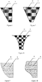
Figure 1 is a schematic diagram of a main view of a broadband ultrathin acoustic wave diffusion structure. -
Figure 2 is a schematic diagram of a side section of a broadband ultrathin acoustic wave diffusion structure. -
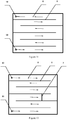
Figure 3 is a schematic diagram of a side section of an acoustic wave diffusion unit. -
Figure 4 is a schematic diagram of a side section of an acoustic wave diffusion unit. -
Figure 5 is a schematic diagram of a side section of an acoustic wave diffusion unit. -
Figure 6 is a sectional diagram of an acoustic wave focused section. -
Figure 7 is a sectional diagram of an acoustic wave focused section. -
Figure 8 is a sectional diagram of an acoustic wave focused section. -
Figure 9 is a sectional diagram of an acoustic wave focused section. -
Figure 10 is a sectional diagram of an acoustic wave focused section. -
Figure 11 is a monolayer schematic diagram of an acoustic wave propagation section. -
Figure 12 is a monolayer schematic diagram of an acoustic wave propagation section. -
Figure 13 is a monolayer schematic diagram of an acoustic wave propagation section. -
Figure 14 is a monolayer schematic diagram of an acoustic wave propagation section. -
Figure 15 is a monolayer schematic diagram of an acoustic wave propagation section. -
Figure 16 is a monolayer schematic diagram of an acoustic wave propagation section. - In the
figures: 1 acoustic wave diffusion unit; 2 acoustic wave focused section; 3 acoustic wave propagation section; 4 acoustic material filled in acoustic wave focused cavity; 5 membrane or string net embedded in acoustic material; 6 wall of acoustic wave focused cavity; 7 isolated wall between simply connected acoustic wave propagation passages belonging to different acoustic wave diffusion units; 8 simply connected acoustic wave propagation passage; 9 wall of simply connected acoustic wave propagation passage; 10 communication hole between adjacent layers of laminated simply connected acoustic wave propagation passages. - The arrow in the figure indicates the direction of propagation of the acoustic wave, wherein a solid line with arrow indicates propagation of the acoustic wave in its own acoustic wave diffusion unit; and a dotted line with arrow indicates propagation of the acoustic wave from other acoustic wave diffusion units in the acoustic wave diffusion unit.
- A plurality of acoustic wave diffusion units are arranged along a body surface to form a broadband ultrathin acoustic wave diffusion structure, as shown in Figure and
Figure 2 . Each acousticwave diffusion unit 1 comprises at least one acousticwave propagation section 3, and an acoustic wave focusedsection 2 communicating with the acousticwave propagation section 3 is arranged according to needs. - The acoustic wave focused
section 2 is formed by a through cavity filled with acoustic material. The sectional diagram of the acoustic wave focusedsection 2 is shown inFigure 6 . The acoustic wave focused cavity is a variable-section cavity, and the end surface of the cavity is a hexagon. Theacoustic material 4 is filled in the variable-section cavity, andmultilayer membranes 5 are embedded at equal spacing in the variable-section cavity. - The acoustic
wave propagation section 3 is formed by a simply connected acousticwave propagation passage 8 with a close end, and its monolayer schematic diagrams are shown inFigure 11 and Figure 12 . Different acousticwave diffusion units 1 have different lengths of the simply connected acousticwave propagation passages 8. - In the broadband ultrathin acoustic wave diffusion structure, the arrangement solutions of the simply connected acoustic
wave propagation passages 8 in different acoustic wave diffusion units are as follows: - (1) Some acoustic
wave diffusion units 1 have no acoustic wave focusedsection 2, and only comprise the acousticwave propagation sections 3, and their simply connected acousticwave propagation passages 8 are short, as shown by a shallow cavity region occupied by the solid line with arrow inFigure 5 . The acousticwave propagation sections 3 only occupy part of the available spaces of their own acousticwave diffusion units 1. - (2) Some acoustic
wave diffusion units 1 comprise the acoustic wave focusedsections 2 and the acousticwave propagation sections 3, and their simply connected acousticwave propagation passages 8 are long. These simply connected acousticwave propagation passages 8 are designed into narrow and long passages inside their own acoustic wave diffusion units by the measures of circuity, bending, coiling or stacking in a monolayer or multilayer or spatial spiral structural form. The acousticwave propagation sections 3 occupy part of available space of their own acousticwave diffusion units 1, as shown by regions occupied by the solid lines with arrows in the acoustic wave propagation sections inFigure 3 andFigure 12 . In thefigure, 10 indicates a communication hole between adjacent layers of laminated simply connected acousticwave propagation passages 8. - (3) Some acoustic
wave diffusion units 1 comprise acoustic wave focusedsections 2 and acousticwave propagation sections 3, and their simply connected acousticwave propagation passages 8 are long. These simply connected acousticwave propagation passages 8 are designed into narrow and long passages inside their own acoustic wave diffusion units by the measures of circuity, bending, coiling or stacking inside the acoustic wave diffusion unit in a multilayer or spatial spiral structural form. The acousticwave propagation sections 3 occupy the whole of available space of their own acousticwave diffusion units 1, as shown inFigure 4 andFigure 11 . In thefigure, 10 indicates a communication hole between adjacent layers of laminated simply connected acousticwave propagation passages 8. - (4) Some acoustic
wave diffusion units 1 comprise acoustic wave focusedsections 2 and acousticwave propagation sections 3, and their simply connected acousticwave propagation passages 8 are very long. These simply connected acousticwave propagation passages 8 are designed into narrow and long passages inside the broadband ultrathin acoustic wave diffusion structure by the measures of circuity, bending, coiling or stacking in a multilayer or spatial spiral structural form. These simply connected acousticwave propagation passages 8 occupy the whole of available space of their own acoustic wave diffusion units and also extend to other acoustic wave diffusion units to occupy the remaining available space inside other acoustic wave diffusion units, especially occupy the remaining space of the acoustic wave diffusion units with short simply connected acousticwave propagation passages 8, as shown inFigure 2 ,Figure 3 ,Figure 5 andFigure 12 . The regions occupied by the dotted line with arrow indicate extension of the simply connected acousticwave propagation passages 8 of other acoustic wave diffusion units in the acoustic wave diffusion unit. In thefigure, 7 indicates an isolated wall between simply connected acousticwave propagation passages 8 of this acoustic wave diffusion unit and another acoustic wave diffusion unit. - For the broadband ultrathin acoustic wave diffusion structure, first, external acoustic waves enter the acoustic wave focused
section 2, and are focused by the variable-section cavity and the acoustic material filled therein. Then, the focused acoustic waves enter the acousticwave propagation section 3, and propagate and reflect in the simply connected acousticwave propagation passages 8. The maximum length of the simply connected acousticwave propagation passage 8 may be dozens or even hundreds of times of the thickness of the broadband ultrathin acoustic wave diffusion structure. - The present embodiment is substantially the same as
embodiment 1, and is different fromembodiment 1 in that: (1) the cavity end surface of the acoustic wave focused section, as shown inFigure 7 , is a quadrangle. Theacoustic material 4 is filled in the variable-section cavity, andmultilayer fibers 5 are embedded at equal spacing in the cavity. (2) The monolayer schematic diagrams of the simply connected acousticwave propagation passage 8 of the acousticwave propagation section 3 are shown inFigure 13 and Figure 14 . - The present embodiment is substantially the same as
embodiment 1, and is different fromembodiment 1 in that: (1) the cavity end surface of the acoustic wave focused section, as shown inFigure 8 , is a circle. Theacoustic material 4 is filled in the variable-section cavity, andmultilayer silks 5 are embedded at different spacings in the cavity. (2) The monolayer schematic diagrams of the simply connected acousticwave propagation passage 8 of the acousticwave propagation section 3 are shown inFigure 15 and Figure 16 . - The present embodiment is substantially the same as
embodiment 1, and is different fromembodiment 1 in that: the cavity end surface of the acoustic wave focused section, as shown inFigure 9 , is a pentagon. Theacoustic material 4 is filled in the variable-section cavity, and multilayermetal string nets 5 are embedded at equal spacing in the cavity. - The present embodiment is substantially the same as
embodiment 1, and is different fromembodiment 1 in that: the cavity end surface of the acoustic wave focused section, as shown inFigure 10 , is an oval. Theacoustic material 4 is filled in the variable-section cavity, andmultilayer cloth 5 are embedded at different spacings in the cavity.
Claims (8)
- A broadband ultrathin acoustic wave diffusion structure, comprising a plurality of acoustic wave diffusion units, wherein each acoustic wave diffusion unit comprises at least one acoustic wave propagation section, and an acoustic wave focused section communicating with the acoustic wave propagation section is arranged according to needs;
the acoustic wave focused section is formed by an acoustic wave focused cavity filled with acoustic material; the acoustic wave focused cavity is a variable-section cavity, and isotropic or anisotropic acoustic material is filled in the variable-section cavity;
the acoustic wave propagation section is formed by a simply connected acoustic wave propagation passage with a close end; and
in different acoustic wave diffusion units, the simply connected acoustic wave propagation passages have different lengths; some acoustic wave diffusion units have no acoustic wave focused section, and only comprise the acoustic wave propagation sections; some acoustic wave diffusion units comprise acoustic wave focused sections and acoustic wave propagation sections, and the acoustic wave focused cavities of the acoustic wave focused sections communicate with the simply connected acoustic wave propagation passages of the acoustic wave propagation sections; for the acoustic wave diffusion unit comprising the acoustic wave focused section and the acoustic wave propagation section, the simply connected acoustic wave propagation passage of the acoustic wave propagation section is closely arranged through the measures of circuity, bending, coiling or stacking in a monolayer or multilayer or spatial spiral structural form, and occupies part or whole of available space of the broadband ultrathin acoustic wave diffusion structure. - The broadband ultrathin acoustic wave diffusion structure of claim 1, wherein the anisotropic acoustic material is formed by embedding membranes or string nets into the isotropic acoustic material.
- The broadband ultrathin acoustic wave diffusion structure of claim 1 or 2, wherein for the acoustic wave diffusion unit comprising the acoustic wave focused section and the acoustic wave propagation section, the arrangement solutions of the simply connected acoustic wave propagation passage of the acoustic wave propagation section include:(1) the simply connected acoustic wave propagation passage is closely arranged inside its own acoustic wave diffusion unit through the measures of circuity, bending, coiling or stacking in a monolayer or multilayer or spatial spiral structural form, and occupies the part or the whole of available space outside the acoustic wave focused section; and(2) the simply connected acoustic wave propagation passage is closely arranged inside the broadband ultrathin acoustic wave diffusion structure through the measures of circuity, bending, coiling or stacking in a monolayer or multilayer or spatial spiral structural form, occupies the whole of available space inside its own acoustic wave diffusion unit and also extends to other acoustic wave diffusion units to occupy the remaining available space inside other acoustic wave diffusion units, especially occupy the remaining space of the acoustic wave diffusion units with short simply connected acoustic wave propagation passages.
- The broadband ultrathin acoustic wave diffusion structure of claim 1 or 2, wherein the membrane of the anisotropic acoustic material is a non-porous membrane or porous membrane, and is made of metal or nonmetallic, including cotton, fiber, silk, burlap, woolen cloth, mixture yarn and leather; and the string net of the anisotropic acoustic material is made of metal or nonmetallic.
- The broadband ultrathin acoustic wave diffusion structure of claim 3, wherein the membrane of the anisotropic acoustic material is a non-porous membrane or porous membrane, and is made of metal or nonmetallic, including cotton, fiber, silk, burlap, woolen cloth, mixture yarn and leather; and the string net of the anisotropic acoustic material is made of metal or nonmetallic.
- The broadband ultrathin acoustic wave diffusion structure of claim 1, 2 or 5, wherein the acoustic material is gas material, solid material or liquid material, including air, helium, gel, polyurethane, polyester, epoxy resin, foamed plastics, foamed metal, soft rubber, silicone rubber, butyl rubber, glass wool, glass fiber, felt, silk, cloth and micro-perforated panel.
- The broadband ultrathin acoustic wave diffusion structure of claim 3, wherein the acoustic material is gas material, solid material or liquid material, including air, helium, gel, polyurethane, polyester, epoxy resin, foamed plastics, foamed metal, soft rubber, silicone rubber, butyl rubber, glass wool, glass fiber, felt, silk, cloth and micro-perforated panel.
- The broadband ultrathin acoustic wave diffusion structure of claim 4, wherein the acoustic material is gas material, solid material or liquid material, including air, helium, gel, polyurethane, polyester, epoxy resin, foamed plastics, foamed metal, soft rubber, silicone rubber, butyl rubber, glass wool, glass fiber, felt, silk, cloth and micro-perforated panel.
Applications Claiming Priority (1)
| Application Number | Priority Date | Filing Date | Title |
|---|---|---|---|
| PCT/CN2017/082072 WO2018195835A1 (en) | 2017-04-26 | 2017-04-26 | Broadband ultrathin sound wave diffusion structure |
Publications (3)
| Publication Number | Publication Date |
|---|---|
| EP3570560A1 true EP3570560A1 (en) | 2019-11-20 |
| EP3570560A4 EP3570560A4 (en) | 2020-02-19 |
| EP3570560B1 EP3570560B1 (en) | 2021-01-20 |
Family
ID=63917880
Family Applications (1)
| Application Number | Title | Priority Date | Filing Date |
|---|---|---|---|
| EP17907955.3A Not-in-force EP3570560B1 (en) | 2017-04-26 | 2017-04-26 | Broadband ultrathin sound wave diffusion structure |
Country Status (3)
| Country | Link |
|---|---|
| US (1) | US11335311B2 (en) |
| EP (1) | EP3570560B1 (en) |
| WO (1) | WO2018195835A1 (en) |
Cited By (1)
| Publication number | Priority date | Publication date | Assignee | Title |
|---|---|---|---|---|
| EP4567787A1 (en) | 2023-12-06 | 2025-06-11 | Akademia Gorniczo-Hutnicza im. Stanislawa Staszica w Krakowie | An acoustic panel having a property of shaping a directivity characteristic of a reflected acoustic wave |
Family Cites Families (12)
| Publication number | Priority date | Publication date | Assignee | Title |
|---|---|---|---|---|
| FR2240813B1 (en) * | 1973-08-16 | 1976-04-30 | France Etat | |
| JPS6118997A (en) * | 1984-07-06 | 1986-01-27 | 株式会社ブリヂストン | Sound wave controller |
| SU1420198A1 (en) * | 1986-12-10 | 1988-08-30 | О. С. Кочетов, Ю. А. Дубинский и В. В. Р бов | Noise silencer |
| US4800983A (en) * | 1987-01-13 | 1989-01-31 | Geren David K | Energized acoustic labyrinth |
| FR2862798B1 (en) * | 2003-11-21 | 2006-03-17 | Snecma Moteurs | INSONORIZING BALL PANEL AND METHOD OF MAKING SAME |
| WO2008154215A1 (en) * | 2007-06-11 | 2008-12-18 | Bonnie Schnitta | Architectural acoustic device |
| JP5359167B2 (en) * | 2008-10-07 | 2013-12-04 | ヤマハ株式会社 | Car body structure and luggage compartment |
| CN102689477B (en) * | 2011-03-22 | 2016-02-03 | 三香科技股份有限公司 | Sound-absorbing composite structure |
| CN102251829B (en) * | 2011-06-21 | 2012-11-21 | 陈尔斌 | Silencing unit and internal-combustion engine exhaust silencer using same |
| CN106382432A (en) | 2016-11-22 | 2017-02-08 | 苏州大学 | Helmholtz resonant silencing unit based on maze structure and resonant silencer |
| CN107071663B (en) * | 2017-04-26 | 2022-09-06 | 大连理工大学 | Broadband ultra-thin sound wave diffusion structure |
| US11164559B2 (en) * | 2018-04-30 | 2021-11-02 | Toyota Motor Engineering & Manufacturing North America, Inc. | Selective sound transmission and active sound transmission control |
-
2017
- 2017-04-26 EP EP17907955.3A patent/EP3570560B1/en not_active Not-in-force
- 2017-04-26 US US16/487,389 patent/US11335311B2/en active Active
- 2017-04-26 WO PCT/CN2017/082072 patent/WO2018195835A1/en not_active Ceased
Cited By (1)
| Publication number | Priority date | Publication date | Assignee | Title |
|---|---|---|---|---|
| EP4567787A1 (en) | 2023-12-06 | 2025-06-11 | Akademia Gorniczo-Hutnicza im. Stanislawa Staszica w Krakowie | An acoustic panel having a property of shaping a directivity characteristic of a reflected acoustic wave |
Also Published As
| Publication number | Publication date |
|---|---|
| EP3570560A4 (en) | 2020-02-19 |
| US11335311B2 (en) | 2022-05-17 |
| WO2018195835A1 (en) | 2018-11-01 |
| EP3570560B1 (en) | 2021-01-20 |
| US20190378488A1 (en) | 2019-12-12 |
Similar Documents
| Publication | Publication Date | Title |
|---|---|---|
| EP3570273A1 (en) | Broadband ultra-thin sound absorbing and insulating structure controlling sound wave propagation path | |
| CN103443851B (en) | Sound penetrability material and the sound comprising the building occupancy using this material adjust surface construction, microphone windscreen, protection grid, sound penetrability projection screen and loudspeaker | |
| MY205725A (en) | Low-frequency coupling sound-absorbing structure | |
| US2502016A (en) | Diffraction type sound absorber | |
| CN107071663B (en) | Broadband ultra-thin sound wave diffusion structure | |
| CN106952640A (en) | Broadband ultra-thin sound-absorbing and sound-insulating structure for controlling sound wave propagation path | |
| CN104732967B (en) | Sound absorption screen for absorbing sound by using coplanar hollow tube | |
| CN204303339U (en) | A kind of compound sound-absorption structural | |
| US20180035199A1 (en) | Loudspeaker module and electronic product | |
| CN104464711B (en) | The broad band low frequency sound absorber of periodic structure design level is cascaded as with the weak elasticity of sound-absorbing material unit | |
| CN207032561U (en) | A kind of sound-proof wall body structure | |
| US9570061B2 (en) | Acoustic material and wire harness with acoustic material | |
| CN206741932U (en) | Control the ultra-thin sound absorption and insulation structure in broadband of acoustic wave propagation path | |
| CN105989829A (en) | Multi-layer diaphragm type composite resonance sound absorption module | |
| US11335311B2 (en) | Broadband ultrathin acoustic wave diffusion structure | |
| JP6781766B2 (en) | Soundproof structure and manufacturing method of soundproof structure | |
| CN105898648B (en) | A Novel Ultrathin Sonic Impedance Transformer | |
| CN204728522U (en) | A kind of sound-proof wall body structure | |
| CN206556222U (en) | A kind of airduct sound-deadening and noise-reducing device and air duct structure | |
| CN109185233A (en) | The fractal structure acoustic metamaterial device of for transformer noise reduction | |
| CN214402251U (en) | Curtain type sound-absorbing wedge structure | |
| CN203872334U (en) | Minisize loudspeaker system and electronic device | |
| CN206879082U9 (en) | Broadband Ultrathin Acoustic Diffusion Structure | |
| CN107514066A (en) | A kind of lightweight sound insulation room device based on extension tube resonant structure | |
| CN206711599U (en) | A kind of cycle born of the same parents structure composite sound panel |
Legal Events
| Date | Code | Title | Description |
|---|---|---|---|
| STAA | Information on the status of an ep patent application or granted ep patent |
Free format text: STATUS: THE INTERNATIONAL PUBLICATION HAS BEEN MADE |
|
| PUAI | Public reference made under article 153(3) epc to a published international application that has entered the european phase |
Free format text: ORIGINAL CODE: 0009012 |
|
| STAA | Information on the status of an ep patent application or granted ep patent |
Free format text: STATUS: REQUEST FOR EXAMINATION WAS MADE |
|
| 17P | Request for examination filed |
Effective date: 20190813 |
|
| AK | Designated contracting states |
Kind code of ref document: A1 Designated state(s): AL AT BE BG CH CY CZ DE DK EE ES FI FR GB GR HR HU IE IS IT LI LT LU LV MC MK MT NL NO PL PT RO RS SE SI SK SM TR |
|
| AX | Request for extension of the european patent |
Extension state: BA ME |
|
| A4 | Supplementary search report drawn up and despatched |
Effective date: 20200121 |
|
| RIC1 | Information provided on ipc code assigned before grant |
Ipc: H04R 9/02 20060101ALI20200115BHEP Ipc: H04R 9/06 20060101AFI20200115BHEP |
|
| DAV | Request for validation of the european patent (deleted) | ||
| DAX | Request for extension of the european patent (deleted) | ||
| REG | Reference to a national code |
Ref country code: DE Ref legal event code: R079 Ref document number: 602017031908 Country of ref document: DE Free format text: PREVIOUS MAIN CLASS: H04R0009060000 Ipc: G10K0011180000 |
|
| GRAP | Despatch of communication of intention to grant a patent |
Free format text: ORIGINAL CODE: EPIDOSNIGR1 |
|
| STAA | Information on the status of an ep patent application or granted ep patent |
Free format text: STATUS: GRANT OF PATENT IS INTENDED |
|
| RIC1 | Information provided on ipc code assigned before grant |
Ipc: H04R 9/06 20060101ALI20200921BHEP Ipc: H04R 9/02 20060101ALI20200921BHEP Ipc: G10K 11/18 20060101AFI20200921BHEP |
|
| INTG | Intention to grant announced |
Effective date: 20201027 |
|
| GRAS | Grant fee paid |
Free format text: ORIGINAL CODE: EPIDOSNIGR3 |
|
| GRAA | (expected) grant |
Free format text: ORIGINAL CODE: 0009210 |
|
| STAA | Information on the status of an ep patent application or granted ep patent |
Free format text: STATUS: THE PATENT HAS BEEN GRANTED |
|
| AK | Designated contracting states |
Kind code of ref document: B1 Designated state(s): AL AT BE BG CH CY CZ DE DK EE ES FI FR GB GR HR HU IE IS IT LI LT LU LV MC MK MT NL NO PL PT RO RS SE SI SK SM TR |
|
| REG | Reference to a national code |
Ref country code: GB Ref legal event code: FG4D |
|
| REG | Reference to a national code |
Ref country code: CH Ref legal event code: EP |
|
| REG | Reference to a national code |
Ref country code: DE Ref legal event code: R096 Ref document number: 602017031908 Country of ref document: DE |
|
| REG | Reference to a national code |
Ref country code: AT Ref legal event code: REF Ref document number: 1357068 Country of ref document: AT Kind code of ref document: T Effective date: 20210215 |
|
| REG | Reference to a national code |
Ref country code: IE Ref legal event code: FG4D |
|
| REG | Reference to a national code |
Ref country code: NL Ref legal event code: MP Effective date: 20210120 |
|
| REG | Reference to a national code |
Ref country code: LT Ref legal event code: MG9D |
|
| REG | Reference to a national code |
Ref country code: AT Ref legal event code: MK05 Ref document number: 1357068 Country of ref document: AT Kind code of ref document: T Effective date: 20210120 |
|
| PG25 | Lapsed in a contracting state [announced via postgrant information from national office to epo] |
Ref country code: NO Free format text: LAPSE BECAUSE OF FAILURE TO SUBMIT A TRANSLATION OF THE DESCRIPTION OR TO PAY THE FEE WITHIN THE PRESCRIBED TIME-LIMIT Effective date: 20210420 Ref country code: PT Free format text: LAPSE BECAUSE OF FAILURE TO SUBMIT A TRANSLATION OF THE DESCRIPTION OR TO PAY THE FEE WITHIN THE PRESCRIBED TIME-LIMIT Effective date: 20210520 Ref country code: GR Free format text: LAPSE BECAUSE OF FAILURE TO SUBMIT A TRANSLATION OF THE DESCRIPTION OR TO PAY THE FEE WITHIN THE PRESCRIBED TIME-LIMIT Effective date: 20210421 Ref country code: HR Free format text: LAPSE BECAUSE OF FAILURE TO SUBMIT A TRANSLATION OF THE DESCRIPTION OR TO PAY THE FEE WITHIN THE PRESCRIBED TIME-LIMIT Effective date: 20210120 Ref country code: FI Free format text: LAPSE BECAUSE OF FAILURE TO SUBMIT A TRANSLATION OF THE DESCRIPTION OR TO PAY THE FEE WITHIN THE PRESCRIBED TIME-LIMIT Effective date: 20210120 Ref country code: LT Free format text: LAPSE BECAUSE OF FAILURE TO SUBMIT A TRANSLATION OF THE DESCRIPTION OR TO PAY THE FEE WITHIN THE PRESCRIBED TIME-LIMIT Effective date: 20210120 Ref country code: BG Free format text: LAPSE BECAUSE OF FAILURE TO SUBMIT A TRANSLATION OF THE DESCRIPTION OR TO PAY THE FEE WITHIN THE PRESCRIBED TIME-LIMIT Effective date: 20210420 |
|
| PG25 | Lapsed in a contracting state [announced via postgrant information from national office to epo] |
Ref country code: SE Free format text: LAPSE BECAUSE OF FAILURE TO SUBMIT A TRANSLATION OF THE DESCRIPTION OR TO PAY THE FEE WITHIN THE PRESCRIBED TIME-LIMIT Effective date: 20210120 Ref country code: AT Free format text: LAPSE BECAUSE OF FAILURE TO SUBMIT A TRANSLATION OF THE DESCRIPTION OR TO PAY THE FEE WITHIN THE PRESCRIBED TIME-LIMIT Effective date: 20210120 Ref country code: LV Free format text: LAPSE BECAUSE OF FAILURE TO SUBMIT A TRANSLATION OF THE DESCRIPTION OR TO PAY THE FEE WITHIN THE PRESCRIBED TIME-LIMIT Effective date: 20210120 Ref country code: PL Free format text: LAPSE BECAUSE OF FAILURE TO SUBMIT A TRANSLATION OF THE DESCRIPTION OR TO PAY THE FEE WITHIN THE PRESCRIBED TIME-LIMIT Effective date: 20210120 Ref country code: RS Free format text: LAPSE BECAUSE OF FAILURE TO SUBMIT A TRANSLATION OF THE DESCRIPTION OR TO PAY THE FEE WITHIN THE PRESCRIBED TIME-LIMIT Effective date: 20210120 |
|
| PG25 | Lapsed in a contracting state [announced via postgrant information from national office to epo] |
Ref country code: IS Free format text: LAPSE BECAUSE OF FAILURE TO SUBMIT A TRANSLATION OF THE DESCRIPTION OR TO PAY THE FEE WITHIN THE PRESCRIBED TIME-LIMIT Effective date: 20210520 |
|
| REG | Reference to a national code |
Ref country code: DE Ref legal event code: R097 Ref document number: 602017031908 Country of ref document: DE |
|
| PG25 | Lapsed in a contracting state [announced via postgrant information from national office to epo] |
Ref country code: SM Free format text: LAPSE BECAUSE OF FAILURE TO SUBMIT A TRANSLATION OF THE DESCRIPTION OR TO PAY THE FEE WITHIN THE PRESCRIBED TIME-LIMIT Effective date: 20210120 Ref country code: EE Free format text: LAPSE BECAUSE OF FAILURE TO SUBMIT A TRANSLATION OF THE DESCRIPTION OR TO PAY THE FEE WITHIN THE PRESCRIBED TIME-LIMIT Effective date: 20210120 Ref country code: CZ Free format text: LAPSE BECAUSE OF FAILURE TO SUBMIT A TRANSLATION OF THE DESCRIPTION OR TO PAY THE FEE WITHIN THE PRESCRIBED TIME-LIMIT Effective date: 20210120 |
|
| PLBE | No opposition filed within time limit |
Free format text: ORIGINAL CODE: 0009261 |
|
| STAA | Information on the status of an ep patent application or granted ep patent |
Free format text: STATUS: NO OPPOSITION FILED WITHIN TIME LIMIT |
|
| PG25 | Lapsed in a contracting state [announced via postgrant information from national office to epo] |
Ref country code: DK Free format text: LAPSE BECAUSE OF FAILURE TO SUBMIT A TRANSLATION OF THE DESCRIPTION OR TO PAY THE FEE WITHIN THE PRESCRIBED TIME-LIMIT Effective date: 20210120 Ref country code: SK Free format text: LAPSE BECAUSE OF FAILURE TO SUBMIT A TRANSLATION OF THE DESCRIPTION OR TO PAY THE FEE WITHIN THE PRESCRIBED TIME-LIMIT Effective date: 20210120 Ref country code: RO Free format text: LAPSE BECAUSE OF FAILURE TO SUBMIT A TRANSLATION OF THE DESCRIPTION OR TO PAY THE FEE WITHIN THE PRESCRIBED TIME-LIMIT Effective date: 20210120 Ref country code: MC Free format text: LAPSE BECAUSE OF FAILURE TO SUBMIT A TRANSLATION OF THE DESCRIPTION OR TO PAY THE FEE WITHIN THE PRESCRIBED TIME-LIMIT Effective date: 20210120 |
|
| 26N | No opposition filed |
Effective date: 20211021 |
|
| PG25 | Lapsed in a contracting state [announced via postgrant information from national office to epo] |
Ref country code: LU Free format text: LAPSE BECAUSE OF NON-PAYMENT OF DUE FEES Effective date: 20210426 |
|
| REG | Reference to a national code |
Ref country code: BE Ref legal event code: MM Effective date: 20210430 |
|
| PG25 | Lapsed in a contracting state [announced via postgrant information from national office to epo] |
Ref country code: CH Free format text: LAPSE BECAUSE OF NON-PAYMENT OF DUE FEES Effective date: 20210430 Ref country code: AL Free format text: LAPSE BECAUSE OF FAILURE TO SUBMIT A TRANSLATION OF THE DESCRIPTION OR TO PAY THE FEE WITHIN THE PRESCRIBED TIME-LIMIT Effective date: 20210120 Ref country code: LI Free format text: LAPSE BECAUSE OF NON-PAYMENT OF DUE FEES Effective date: 20210430 Ref country code: ES Free format text: LAPSE BECAUSE OF FAILURE TO SUBMIT A TRANSLATION OF THE DESCRIPTION OR TO PAY THE FEE WITHIN THE PRESCRIBED TIME-LIMIT Effective date: 20210120 |
|
| PG25 | Lapsed in a contracting state [announced via postgrant information from national office to epo] |
Ref country code: SI Free format text: LAPSE BECAUSE OF FAILURE TO SUBMIT A TRANSLATION OF THE DESCRIPTION OR TO PAY THE FEE WITHIN THE PRESCRIBED TIME-LIMIT Effective date: 20210120 |
|
| PG25 | Lapsed in a contracting state [announced via postgrant information from national office to epo] |
Ref country code: IT Free format text: LAPSE BECAUSE OF FAILURE TO SUBMIT A TRANSLATION OF THE DESCRIPTION OR TO PAY THE FEE WITHIN THE PRESCRIBED TIME-LIMIT Effective date: 20210120 Ref country code: IE Free format text: LAPSE BECAUSE OF NON-PAYMENT OF DUE FEES Effective date: 20210426 |
|
| PG25 | Lapsed in a contracting state [announced via postgrant information from national office to epo] |
Ref country code: IS Free format text: LAPSE BECAUSE OF FAILURE TO SUBMIT A TRANSLATION OF THE DESCRIPTION OR TO PAY THE FEE WITHIN THE PRESCRIBED TIME-LIMIT Effective date: 20210520 Ref country code: FR Free format text: LAPSE BECAUSE OF NON-PAYMENT OF DUE FEES Effective date: 20210430 |
|
| PG25 | Lapsed in a contracting state [announced via postgrant information from national office to epo] |
Ref country code: BE Free format text: LAPSE BECAUSE OF NON-PAYMENT OF DUE FEES Effective date: 20210430 |
|
| PG25 | Lapsed in a contracting state [announced via postgrant information from national office to epo] |
Ref country code: CY Free format text: LAPSE BECAUSE OF FAILURE TO SUBMIT A TRANSLATION OF THE DESCRIPTION OR TO PAY THE FEE WITHIN THE PRESCRIBED TIME-LIMIT Effective date: 20210120 Ref country code: NL Free format text: LAPSE BECAUSE OF NON-PAYMENT OF DUE FEES Effective date: 20210120 |
|
| PG25 | Lapsed in a contracting state [announced via postgrant information from national office to epo] |
Ref country code: HU Free format text: LAPSE BECAUSE OF FAILURE TO SUBMIT A TRANSLATION OF THE DESCRIPTION OR TO PAY THE FEE WITHIN THE PRESCRIBED TIME-LIMIT; INVALID AB INITIO Effective date: 20170426 |
|
| PG25 | Lapsed in a contracting state [announced via postgrant information from national office to epo] |
Ref country code: MK Free format text: LAPSE BECAUSE OF FAILURE TO SUBMIT A TRANSLATION OF THE DESCRIPTION OR TO PAY THE FEE WITHIN THE PRESCRIBED TIME-LIMIT Effective date: 20210120 |
|
| PG25 | Lapsed in a contracting state [announced via postgrant information from national office to epo] |
Ref country code: TR Free format text: LAPSE BECAUSE OF FAILURE TO SUBMIT A TRANSLATION OF THE DESCRIPTION OR TO PAY THE FEE WITHIN THE PRESCRIBED TIME-LIMIT Effective date: 20210120 |
|
| PGFP | Annual fee paid to national office [announced via postgrant information from national office to epo] |
Ref country code: GB Payment date: 20240424 Year of fee payment: 8 |
|
| PGFP | Annual fee paid to national office [announced via postgrant information from national office to epo] |
Ref country code: DE Payment date: 20240425 Year of fee payment: 8 |
|
| PG25 | Lapsed in a contracting state [announced via postgrant information from national office to epo] |
Ref country code: MT Free format text: LAPSE BECAUSE OF FAILURE TO SUBMIT A TRANSLATION OF THE DESCRIPTION OR TO PAY THE FEE WITHIN THE PRESCRIBED TIME-LIMIT Effective date: 20210120 |
|
| REG | Reference to a national code |
Ref country code: DE Ref legal event code: R119 Ref document number: 602017031908 Country of ref document: DE |
|
| GBPC | Gb: european patent ceased through non-payment of renewal fee |
Effective date: 20250426 |
|
| PG25 | Lapsed in a contracting state [announced via postgrant information from national office to epo] |
Ref country code: DE Free format text: LAPSE BECAUSE OF NON-PAYMENT OF DUE FEES Effective date: 20251104 |
|
| PG25 | Lapsed in a contracting state [announced via postgrant information from national office to epo] |
Ref country code: GB Free format text: LAPSE BECAUSE OF NON-PAYMENT OF DUE FEES Effective date: 20250426 |