EP3570418A1 - Ableitungseinrichtung - Google Patents
Ableitungseinrichtung Download PDFInfo
- Publication number
- EP3570418A1 EP3570418A1 EP19180934.2A EP19180934A EP3570418A1 EP 3570418 A1 EP3570418 A1 EP 3570418A1 EP 19180934 A EP19180934 A EP 19180934A EP 3570418 A1 EP3570418 A1 EP 3570418A1
- Authority
- EP
- European Patent Office
- Prior art keywords
- contact
- strand
- shaft
- discharge device
- carbon fibers
- Prior art date
- Legal status (The legal status is an assumption and is not a legal conclusion. Google has not performed a legal analysis and makes no representation as to the accuracy of the status listed.)
- Granted
Links
- 229920000049 Carbon (fiber) Polymers 0.000 claims abstract description 11
- 239000004917 carbon fiber Substances 0.000 claims abstract description 11
- 239000000835 fiber Substances 0.000 claims abstract description 8
- 238000012544 monitoring process Methods 0.000 claims abstract description 5
- 238000007599 discharging Methods 0.000 abstract description 2
- 238000012423 maintenance Methods 0.000 description 2
- RYGMFSIKBFXOCR-UHFFFAOYSA-N Copper Chemical compound [Cu] RYGMFSIKBFXOCR-UHFFFAOYSA-N 0.000 description 1
- 230000015572 biosynthetic process Effects 0.000 description 1
- 239000002131 composite material Substances 0.000 description 1
- 229910052802 copper Inorganic materials 0.000 description 1
- 239000010949 copper Substances 0.000 description 1
- 230000007797 corrosion Effects 0.000 description 1
- 238000005260 corrosion Methods 0.000 description 1
- 238000007786 electrostatic charging Methods 0.000 description 1
- 238000009413 insulation Methods 0.000 description 1
- 238000005259 measurement Methods 0.000 description 1
- VNWKTOKETHGBQD-UHFFFAOYSA-N methane Chemical compound C VNWKTOKETHGBQD-UHFFFAOYSA-N 0.000 description 1
Images
Classifications
-
- H—ELECTRICITY
- H02—GENERATION; CONVERSION OR DISTRIBUTION OF ELECTRIC POWER
- H02K—DYNAMO-ELECTRIC MACHINES
- H02K11/00—Structural association of dynamo-electric machines with electric components or with devices for shielding, monitoring or protection
- H02K11/40—Structural association with grounding devices
Definitions
- the invention relates to a discharge device according to claim 1.
- Such discharge devices can be used to dissipate electrostatic charge due to frictional effects or external influences, such as lightning strike.
- discharge devices can also be used to dissipate electric charge of motor shafts of electric motors, which may be generated in particular on three-phase motors as a result of a wave-induced electrical current.
- the derivative of the "wave current" is used in particular to prevent electrolytic corrosion in the bearings of the motors.
- the object of the present invention is to make it possible to shorten or avoid maintenance measures.
- the discharge device has for discharging electrostatic charge from a shaft on a contact strand which is arranged tangentially to a contact circumference of the shaft in a frame holder such that in a contact position of the contact strand between this and the contact circumference of the shaft, a contact surface is formed, wherein the contact strand comprises a fiber assembly of a plurality of carbon fibers.
- an electrical device is provided for function monitoring.
- the device for functional monitoring is designed as a resistance measuring device.
- the resistance measuring device can be arranged in a short-circuit loop formed between ends of the contact strand.
- a particularly simple embodiment becomes possible if the fiber arrangement has a multiplicity of carbon fibers extending in the strand direction.
- a particularly resilient embodiment is possible if the fiber arrangement of the contact strand is formed as a strand or cord.
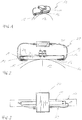
- Fig. 1 shows a discharge device 10 with a arranged in a frame holder 11 contact strand 12, which is formed of a plurality of extending in the strand direction carbon fibers.
- the contact strand 12 is substantially tangent to a Kontak phenomenon 13 of a shaft 14 at.
- the contact strand 12 consists of a plurality of mutually parallel, rectified carbon fibers, which are combined at least at their ends to form a composite with a force introduction 15, 16 are provided.
- the force inputs 15, 16 are each connected via a biasing device 17 formed here as a helical spring with a terminal end 18 and 19 of the frame holder 11.
- a bearing receptacle 21 which allows a connection of the frame holder 11 with a arranged on a frame device not shown bearing axis 22.
- the force inputs 15, 16 are simultaneously used as connection contacts for a short-circuiting loop 23, which is provided with an electrical resistance measuring device 24.
- Fig. 2 How out Fig. 2 is seen between the frame base 20 of the frame holder 11 and the in Fig. 2 left illustrated terminal end 18 is provided as insulating 25 formed insulation, which electrically isolates the terminal end 18 of the frame base 20, so that due to electrostatic charging of the shaft 14 from the contact circumference 13 of the shaft 14 via the contact strand 12 and the frame base 20 in the bearing axis 22nd the frame device derived wave current is inevitably passed through the resistance measuring device 24.
- the resistance measuring device 24 allows an immediate measurement of the electrical resistance formed in the contact strand 12, so that wear of the carbon fiber forming the contact strand 12 or even fiber breakage of carbon fibers can be detected as a corresponding increase of the electrical resistance with the resistance measuring device 24.
- the contact strand 12 of a plurality of rectified and mutually parallel carbon fibers such that the arrangement of the frame holder 11 and the contact strand 12 is approximately comparable to a violin bow
- the contact strand a plurality of carbon fibers is formed, which are stranded together in a strand or formed into a cord, so that an increased tensile strength of the contact strand 12 in such cases is possible, where necessary to work with a particularly high contact pressure.
- the contact strand 12 it is easily possible by a change in the radial distance between the bearing axis 22, on which by means of the bearing seat 21 of the frame holder 11, and the contact circumference 13 of the shaft 14, the contact pressure, radially from the contact strand 12th on the contact circumference 13 of the shaft 14 is exercised to change or adjust.
Landscapes
- Engineering & Computer Science (AREA)
- Power Engineering (AREA)
- Elimination Of Static Electricity (AREA)
- Motor Or Generator Frames (AREA)
- Electrostatic Separation (AREA)
- Preliminary Treatment Of Fibers (AREA)
Abstract
Description
- Die Erfindung betrifft eine Ableitungseinrichtung gemäß Anspruch 1.
- Derartige Ableitungseinrichtungen können zur Ableitung elektrostatischer Aufladung aufgrund von Reibungseffekten oder auch äußerer Einwirkungen, wie beispielsweise Blitzeinschlag, eingesetzt werden. Darüber hinaus können derartige Ableitungseinrichtungen auch zur Ableitung elektrischer Ladung von Motorwellen von Elektromotoren, die insbesondere an Drehstrommotoren in Folge eines welleninduzierten elektrischen Stroms entstehen können, eingesetzt werden. Im letzteren Fall dient die Ableitung des "Wellenstroms" insbesondere zur Vermeidung elektrolytischer Korrosion in den Lagern der Motoren.
- Zur Ausführung von Ableitungseinrichtungen ist es bekannt, eine bürstenförmige Anordnung vorzusehen, bei der eine häufig unter Verwendung von dünnen Kupferdrähten hergestellte Erdungsbürste in Schleifkontakt mit einem Kontaktumfang der Welle angeordnet wird.
- Bei der bekannten, beispielsweise in der
DE 100 13 222 A1 beschriebenen Erdungsbürste mit metallischen Borsten stellt sich jedoch ein erhöhter Verschleiß im Schleifkontakt mit dem Kontaktpartner oder der Welle, aus der die Ladung abgeleitet werden soll, ein. - Aufgabe der vorliegenden Erfindung ist es, eine Verkürzung oder Vermeidung von Wartungsmaßnahmen zu ermöglichen.
- Diese Aufgabe wird durch eine Ableitungseinrichtung mit den Merkmalen des Anspruchs 1 gelöst.
- Die erfindungsgemäße Ableitungseinrichtung weist zur Ableitung elektrostatischer Ladung von einer Welle einen Kontaktstrang auf, der tangential zu einem Kontaktumfang der Welle in einem Rahmenhalter derart angeordnet ist, dass in einer Kontaktstellung des Kontaktstrangs zwischen diesem und dem Kontaktumfang der Welle eine Kontaktfläche ausgebildet ist, wobei der Kontaktstrang eine Faseranordnung aus einer Vielzahl von Kohlenstofffasern aufweist. Zur Verkürzung oder Vermeidung von Wartungsarbeiten ist eine elektrische Einrichtung zur Funktionsüberwachung vorgesehen.
- In einer besonders funktionssicheren Ausführung ist die Einrichtung zur Funktionsüberwachung als Widerstandsmesseinrichtung ausgebildet.
- Vorteilhaft kann die Widerstandsmesseinrichtung in einer zwischen Enden des Kontaktstrangs ausgebildeten Kurzschlussschleife angeordnet sein.
- Eine besonders einfache Ausgestaltung wird möglich, wenn die Faseranordnung eine Vielzahl sich in Strangrichtung erstreckender Kohlenstofffasern aufweist.
- Besonders vorteilhaft ist es, wenn der Rahmenhalter mit einer Vorspanneinrichtung zur Beaufschlagung des Kontaktstrangs mit einer definierten Zugspannung versehen ist.
- Eine besonders belastbare Ausgestaltung wird möglich, wenn die Faseranordnung des Kontaktstrangs als Litze oder Kordel ausgebildet ist.
- Nachfolgend werden bevorzugte Ausführungsformen der Erfindung anhand der Zeichnung näher erläutert. Es zeigen:
- Fig. 1:
- eine Ableitungseinrichtung in Kontakt zu einer Welle in isometrischer Darstellung;
- Fig. 2:
- die in
Fig. 1 dargestellte Ableitungseinrichtung in Seitenansicht; - Fig. 3:
- die in
Fig. 1 dargestellte Ableitungseinrichtung in Draufsicht. -
Fig. 1 zeigt eine Ableitungseinrichtung 10 mit einem in einem Rahmenhalter 11 angeordneten Kontaktstrang 12, der aus einer Vielzahl sich in Strangrichtung erstreckender Kohlenstofffasern gebildet ist. - Wie insbesondere
Fig. 2 zeigt, liegt der Kontaktstrang 12 im Wesentlichen tangential an einem Kontakumfang 13 einer Welle 14 an. Bei dem inFig. 2 dargestellten Ausführungsbeispiel besteht der Kontaktstrang 12 aus einer Vielzahl parallel zueinander verlaufender, gleichgerichteter Kohlenstofffasern, die zumindest an ihren Enden zu einem Verbund zusammengefasst mit einer Krafteinleitung 15, 16 versehen sind. Die Krafteinleitungen 15, 16 sind jeweils über eine hier als Schraubenfeder ausgebildete Vorspanneinrichtung 17 mit einem Anschlussende 18 bzw. 19 des Rahmenhalters 11 verbunden. An einer parallel zum Kontaktstrang 12 verlaufenden, als Rahmenbasis 20 ausgebildeten Rahmenseite des Rahmenhalters 11 ist dieser mit einer Lageraufnahme 21 versehen, die eine Verbindung des Rahmenhalters 11 mit einer an einer nicht näher dargestellten Gestelleinrichtung angeordneten Lagerachse 22 ermöglicht. - Bei dem in
Fig. 2 dargestellten Ausführungsbeispiel werden die Krafteinleitungen 15, 16 gleichzeitig als Anschlusskontakte für eine Kurzschlussschleife 23 genutzt, die mit einer elektrischen Widerstandsmesseinrichtung 24 versehen ist. - Wie aus
Fig. 2 zu sehen ist, ist zwischen der Rahmenbasis 20 des Rahmenhalters 11 und dem inFig. 2 links dargestellten Anschlussende 18 eine als Isolierscheibe 25 ausgebildete Isolierung vorgesehen, die das Anschlussende 18 elektrisch von der Rahmenbasis 20 isoliert, so dass ein aufgrund elektrostatischer Aufladung der Welle 14 vom Kontaktumfang 13 der Welle 14 über den Kontaktstrang 12 und die Rahmenbasis 20 in die Lagerachse 22 der Gestelleinrichtung abgeleiteter Wellenstrom zwangsläufig über die Widerstandsmesseinrichtung 24 geleitet wird. Damit ermöglicht die Widerstandsmesseinrichtung 24 eine unmittelbare Messung des im Kontaktstrang 12 ausgebildeten elektrischen Widerstands, so dass ein Verschleiß der den Kontaktstrang 12 ausbildenden Kohlenstofffasern oder gar ein Faserbruch von Kohlenstofffasern als entsprechender Anstieg des elektrischen Widerstands mit der Widerstandsmesseinrichtung 24 erfassbar ist. - Abweichend von der vorstehend beispielhaft erörterten Ausbildung des Kontaktstrangs 12 aus einer Vielzahl gleichgerichteter und parallel zueinander verlaufender Kohlenstofffasern, derart, dass die Anordnung aus dem Rahmenhalter 11 und dem Kontaktstrang 12 in etwa mit einem Geigenbogen vergleichbar ist, ist es auch vorteilhaft, wenn der Kontaktstrang aus einer Vielzahl von Kohlenstofffasern gebildet ist, die litzenförmig miteinander verwoben oder zu einer Kordel ausgebildet sind, so dass eine erhöhte Zugfestigkeit des Kontaktstrangs 12 in solchen Fällen möglich ist, wo gegebenenfalls mit einem besonders hohen Kontaktdruck gearbeitet werden muss.
- Unabhängig von der Ausbildung des Kontaktstrangs 12 ist es durch eine Änderung des radialen Abstands zwischen der Lagerachse 22, auf der mittels der Lageraufnahme 21 der Rahmenhalter 11 angeordnet ist, und dem Kontaktumfang 13 der Welle 14 leicht möglich, den Kontaktdruck, der radial vom Kontaktstrang 12 auf den Kontaktumfang 13 der Welle 14 ausgeübt wird, zu ändern bzw. einzustellen.
Claims (6)
- Ableitungseinrichtung (10) zur Ableitung elektrostatischer Ladung von einer Welle (14) mit einem Kontaktstrang (12), der tangential zu einem Kontaktumfang (13) der Welle in einem Rahmenhalter (11) derart angeordnet ist, dass in einer Kontaktstellung des Kontaktstrangs zwischen diesem und dem Kontaktumfang der Welle eine Kontaktfläche ausgebildet ist, wobei der Kontaktstrang eine Faseranordnung aus einer Vielzahl von Kohlenstofffasern aufweist, gekennzeichnet durch
eine elektrische Einrichtung zur Funktionsüberwachung. - Ableitungseinrichtung nach Anspruch 1,
dadurch gekennzeichnet,
dass die Einrichtung zur Funktionsüberwachung als Widerstandsmesseinrichtung (24) ausgebildet ist. - Ableitungseinrichtung nach Anspruch 2,
dadurch gekennzeichnet,
dass die Widerstandsmesseinrichtung (24) in einer zwischen Enden des Kontaktstrangs ausgebildeten Kurzschlussschleife (23) angeordnet ist. - Ableitungseinrichtung nach einem der vorangehenden Ansprüche,
dadurch gekennzeichnet,
dass die Faseranordnung eine Vielzahl sich in Strangrichtung erstreckender Kohlenstofffasern aufweist. - Ableitungseinrichtung nach einem der vorangehenden Ansprüche,
dadurch gekennzeichnet,
dass der Rahmenhalter (11) mit einer Vorspanneinrichtung (17) zur Beaufschlagung des Kontaktstrangs (12) mit einer definierten Zugspannung versehen ist. - Ableitungseinrichtung nach einem der vorangehenden Ansprüche,
dadurch gekennzeichnet,
dass die Faseranordnung des Kontaktstrangs als Litze oder Kordel ausgebildet ist.
Applications Claiming Priority (2)
| Application Number | Priority Date | Filing Date | Title |
|---|---|---|---|
| DE202011106899U DE202011106899U1 (de) | 2011-10-19 | 2011-10-19 | Ableitungseinrichtung |
| EP12188553.7A EP2587643B1 (de) | 2011-10-19 | 2012-10-15 | Ableitungseinrichtung |
Related Parent Applications (2)
| Application Number | Title | Priority Date | Filing Date |
|---|---|---|---|
| EP12188553.7A Division EP2587643B1 (de) | 2011-10-19 | 2012-10-15 | Ableitungseinrichtung |
| EP12188553.7A Division-Into EP2587643B1 (de) | 2011-10-19 | 2012-10-15 | Ableitungseinrichtung |
Publications (2)
| Publication Number | Publication Date |
|---|---|
| EP3570418A1 true EP3570418A1 (de) | 2019-11-20 |
| EP3570418B1 EP3570418B1 (de) | 2021-08-11 |
Family
ID=45347568
Family Applications (2)
| Application Number | Title | Priority Date | Filing Date |
|---|---|---|---|
| EP12188553.7A Active EP2587643B1 (de) | 2011-10-19 | 2012-10-15 | Ableitungseinrichtung |
| EP19180934.2A Active EP3570418B1 (de) | 2011-10-19 | 2012-10-15 | Ableitungseinrichtung |
Family Applications Before (1)
| Application Number | Title | Priority Date | Filing Date |
|---|---|---|---|
| EP12188553.7A Active EP2587643B1 (de) | 2011-10-19 | 2012-10-15 | Ableitungseinrichtung |
Country Status (5)
| Country | Link |
|---|---|
| EP (2) | EP2587643B1 (de) |
| DE (1) | DE202011106899U1 (de) |
| DK (1) | DK3570418T3 (de) |
| ES (2) | ES2895157T3 (de) |
| PL (1) | PL2587643T3 (de) |
Families Citing this family (3)
| Publication number | Priority date | Publication date | Assignee | Title |
|---|---|---|---|---|
| DE102015206520A1 (de) * | 2015-04-13 | 2016-10-13 | Schunk Bahn- Und Industrietechnik Gmbh | Ableitungseinrichtung |
| EP3367546A1 (de) * | 2017-02-27 | 2018-08-29 | Siemens Aktiengesellschaft | Vorrichtung und verfahren zur überwachung eines ableitstromes |
| DE102018107260B3 (de) | 2018-03-27 | 2019-05-23 | Schunk Bahn- Und Industrietechnik Gmbh | Ableitungseinrichtung |
Citations (5)
| Publication number | Priority date | Publication date | Assignee | Title |
|---|---|---|---|---|
| US1394211A (en) * | 1917-04-21 | 1921-10-18 | Bertha Webster | Apparatus for discharging static charges |
| US4873512A (en) * | 1984-03-20 | 1989-10-10 | Westinghouse Electric Corp. | Active shaft grounding and diagnotic system |
| US5227950A (en) * | 1991-03-01 | 1993-07-13 | Westinghouse Electric Corp. | Shaft grounding brush and holder |
| DE10013222A1 (de) | 2000-03-17 | 2001-10-04 | Kone Corp | Einrichtung zum Ableiten elektrostatischer Aufladungen an Rolltreppen und Rollsteigen |
| DE102009004060A1 (de) * | 2009-01-08 | 2010-07-15 | Luiken, Enno, Dipl.-Ing. (FH) | Erdungsseil |
Family Cites Families (1)
| Publication number | Priority date | Publication date | Assignee | Title |
|---|---|---|---|---|
| EP1736621A1 (de) * | 2005-06-24 | 2006-12-27 | BUGA Technologies GmbH | Schleifringanordnung |
-
2011
- 2011-10-19 DE DE202011106899U patent/DE202011106899U1/de not_active Expired - Lifetime
-
2012
- 2012-10-15 DK DK19180934.2T patent/DK3570418T3/da active
- 2012-10-15 ES ES19180934T patent/ES2895157T3/es active Active
- 2012-10-15 PL PL12188553T patent/PL2587643T3/pl unknown
- 2012-10-15 EP EP12188553.7A patent/EP2587643B1/de active Active
- 2012-10-15 EP EP19180934.2A patent/EP3570418B1/de active Active
- 2012-10-15 ES ES12188553T patent/ES2791687T3/es active Active
Patent Citations (5)
| Publication number | Priority date | Publication date | Assignee | Title |
|---|---|---|---|---|
| US1394211A (en) * | 1917-04-21 | 1921-10-18 | Bertha Webster | Apparatus for discharging static charges |
| US4873512A (en) * | 1984-03-20 | 1989-10-10 | Westinghouse Electric Corp. | Active shaft grounding and diagnotic system |
| US5227950A (en) * | 1991-03-01 | 1993-07-13 | Westinghouse Electric Corp. | Shaft grounding brush and holder |
| DE10013222A1 (de) | 2000-03-17 | 2001-10-04 | Kone Corp | Einrichtung zum Ableiten elektrostatischer Aufladungen an Rolltreppen und Rollsteigen |
| DE102009004060A1 (de) * | 2009-01-08 | 2010-07-15 | Luiken, Enno, Dipl.-Ing. (FH) | Erdungsseil |
Also Published As
| Publication number | Publication date |
|---|---|
| ES2791687T3 (es) | 2020-11-05 |
| DK3570418T3 (da) | 2021-11-01 |
| EP2587643A2 (de) | 2013-05-01 |
| PL2587643T3 (pl) | 2020-09-21 |
| ES2895157T3 (es) | 2022-02-17 |
| EP3570418B1 (de) | 2021-08-11 |
| DE202011106899U1 (de) | 2011-11-10 |
| EP2587643B1 (de) | 2020-03-11 |
| EP2587643A3 (de) | 2017-06-21 |
Similar Documents
| Publication | Publication Date | Title |
|---|---|---|
| DE202018100111U1 (de) | Modulverbinder | |
| EP2681807B1 (de) | Hochstromsteckverbinder mit ringfederkontaktierung | |
| DE202012013550U1 (de) | Verschaltete Stator-Anordnung eines Elektromotors, Verschaltungseinrichtung sowie Verwendung eines Flachsteckers darin | |
| EP3570418B1 (de) | Ableitungseinrichtung | |
| DE102020112332A1 (de) | Ladedose für ein Elektrofahrzeug, elektrische Anschlussanordnung und Kraftfahrzeug | |
| WO2008132099A1 (de) | Abgreifeinrichtung zum abgreifen einer elektrischen spannung von einer welle einer elektrischen maschine, entsprechender montagesatz und entsprechende elektrische maschine | |
| EP2555329B1 (de) | Hochvolt-Leistungsanschluss einer elektrischen Maschine | |
| DE112014006067T5 (de) | Sammelschiene und Sammelschienenmodul | |
| EP1841010A2 (de) | Elektrischer Kontaktstift | |
| EP2732488B1 (de) | Vorrichtung zum führen eines elektrischen stromes | |
| DE102009040106A1 (de) | Schleifringvorrichtung | |
| EP2695252B1 (de) | Vibrationsfeste schleifringanordnung | |
| DE102017124028A1 (de) | Kabelbaugruppe mit einer Kühlleitung und Zugentlastung | |
| DE102012203842B3 (de) | Schleifringbürste und Halter für Schleifringbürste | |
| DE112010003398T5 (de) | Anschluss-bestückter Draht | |
| EP2584676B1 (de) | Ableitungseinrichtung | |
| EP2875550B1 (de) | Elektrische kontakteinrichtung zur kontaktierung eines elektrischen leiters | |
| DE112015000409B4 (de) | Kunstharzfahrzeugkarosserie-Erdungsstruktur | |
| DE102011085368A1 (de) | Akkupack mit Sicherung | |
| DE102012204829A1 (de) | Schleifringbürsten in Einpresstechnik und Halterung | |
| EP1705957B1 (de) | Elektrischer Heizleiter | |
| DE102012003979B3 (de) | Batterie mit wenigstens zwei Batteriezellen und mit wenigstens einem Verbindungselement | |
| EP2884602A1 (de) | Kohlebürste | |
| EP3421787A1 (de) | Blitzschutzsystem für ein rotorblatt | |
| DE102010055918A1 (de) | Sicherungseinrichtung für eine Hochvoltleitung eines Kraftfahrzeugs und Kraftfahrzeug mit einer solchen |
Legal Events
| Date | Code | Title | Description |
|---|---|---|---|
| PUAI | Public reference made under article 153(3) epc to a published international application that has entered the european phase |
Free format text: ORIGINAL CODE: 0009012 |
|
| STAA | Information on the status of an ep patent application or granted ep patent |
Free format text: STATUS: THE APPLICATION HAS BEEN PUBLISHED |
|
| AC | Divisional application: reference to earlier application |
Ref document number: 2587643 Country of ref document: EP Kind code of ref document: P |
|
| AK | Designated contracting states |
Kind code of ref document: A1 Designated state(s): AL AT BE BG CH CY CZ DE DK EE ES FI FR GB GR HR HU IE IS IT LI LT LU LV MC MK MT NL NO PL PT RO RS SE SI SK SM TR |
|
| RAP1 | Party data changed (applicant data changed or rights of an application transferred) |
Owner name: SCHUNK TRANSIT SYSTEMS GMBH |
|
| STAA | Information on the status of an ep patent application or granted ep patent |
Free format text: STATUS: REQUEST FOR EXAMINATION WAS MADE |
|
| 17P | Request for examination filed |
Effective date: 20200512 |
|
| RBV | Designated contracting states (corrected) |
Designated state(s): AL AT BE BG CH CY CZ DE DK EE ES FI FR GB GR HR HU IE IS IT LI LT LU LV MC MK MT NL NO PL PT RO RS SE SI SK SM TR |
|
| GRAP | Despatch of communication of intention to grant a patent |
Free format text: ORIGINAL CODE: EPIDOSNIGR1 |
|
| STAA | Information on the status of an ep patent application or granted ep patent |
Free format text: STATUS: GRANT OF PATENT IS INTENDED |
|
| INTG | Intention to grant announced |
Effective date: 20210316 |
|
| GRAS | Grant fee paid |
Free format text: ORIGINAL CODE: EPIDOSNIGR3 |
|
| GRAA | (expected) grant |
Free format text: ORIGINAL CODE: 0009210 |
|
| STAA | Information on the status of an ep patent application or granted ep patent |
Free format text: STATUS: THE PATENT HAS BEEN GRANTED |
|
| AC | Divisional application: reference to earlier application |
Ref document number: 2587643 Country of ref document: EP Kind code of ref document: P |
|
| AK | Designated contracting states |
Kind code of ref document: B1 Designated state(s): AL AT BE BG CH CY CZ DE DK EE ES FI FR GB GR HR HU IE IS IT LI LT LU LV MC MK MT NL NO PL PT RO RS SE SI SK SM TR |
|
| REG | Reference to a national code |
Ref country code: CH Ref legal event code: EP |
|
| REG | Reference to a national code |
Ref country code: DE Ref legal event code: R096 Ref document number: 502012016872 Country of ref document: DE |
|
| REG | Reference to a national code |
Ref country code: IE Ref legal event code: FG4D Free format text: LANGUAGE OF EP DOCUMENT: GERMAN Ref country code: AT Ref legal event code: REF Ref document number: 1420406 Country of ref document: AT Kind code of ref document: T Effective date: 20210915 |
|
| REG | Reference to a national code |
Ref country code: DK Ref legal event code: T3 Effective date: 20211027 |
|
| REG | Reference to a national code |
Ref country code: LT Ref legal event code: MG9D |
|
| REG | Reference to a national code |
Ref country code: NL Ref legal event code: MP Effective date: 20210811 |
|
| PG25 | Lapsed in a contracting state [announced via postgrant information from national office to epo] |
Ref country code: FI Free format text: LAPSE BECAUSE OF FAILURE TO SUBMIT A TRANSLATION OF THE DESCRIPTION OR TO PAY THE FEE WITHIN THE PRESCRIBED TIME-LIMIT Effective date: 20210811 Ref country code: RS Free format text: LAPSE BECAUSE OF FAILURE TO SUBMIT A TRANSLATION OF THE DESCRIPTION OR TO PAY THE FEE WITHIN THE PRESCRIBED TIME-LIMIT Effective date: 20210811 Ref country code: SE Free format text: LAPSE BECAUSE OF FAILURE TO SUBMIT A TRANSLATION OF THE DESCRIPTION OR TO PAY THE FEE WITHIN THE PRESCRIBED TIME-LIMIT Effective date: 20210811 Ref country code: HR Free format text: LAPSE BECAUSE OF FAILURE TO SUBMIT A TRANSLATION OF THE DESCRIPTION OR TO PAY THE FEE WITHIN THE PRESCRIBED TIME-LIMIT Effective date: 20210811 Ref country code: PT Free format text: LAPSE BECAUSE OF FAILURE TO SUBMIT A TRANSLATION OF THE DESCRIPTION OR TO PAY THE FEE WITHIN THE PRESCRIBED TIME-LIMIT Effective date: 20211213 Ref country code: NO Free format text: LAPSE BECAUSE OF FAILURE TO SUBMIT A TRANSLATION OF THE DESCRIPTION OR TO PAY THE FEE WITHIN THE PRESCRIBED TIME-LIMIT Effective date: 20211111 Ref country code: BG Free format text: LAPSE BECAUSE OF FAILURE TO SUBMIT A TRANSLATION OF THE DESCRIPTION OR TO PAY THE FEE WITHIN THE PRESCRIBED TIME-LIMIT Effective date: 20211111 Ref country code: LT Free format text: LAPSE BECAUSE OF FAILURE TO SUBMIT A TRANSLATION OF THE DESCRIPTION OR TO PAY THE FEE WITHIN THE PRESCRIBED TIME-LIMIT Effective date: 20210811 |
|
| PGFP | Annual fee paid to national office [announced via postgrant information from national office to epo] |
Ref country code: AT Payment date: 20211019 Year of fee payment: 10 Ref country code: DK Payment date: 20211022 Year of fee payment: 10 Ref country code: ES Payment date: 20211117 Year of fee payment: 10 |
|
| REG | Reference to a national code |
Ref country code: ES Ref legal event code: FG2A Ref document number: 2895157 Country of ref document: ES Kind code of ref document: T3 Effective date: 20220217 |
|
| PG25 | Lapsed in a contracting state [announced via postgrant information from national office to epo] |
Ref country code: PL Free format text: LAPSE BECAUSE OF FAILURE TO SUBMIT A TRANSLATION OF THE DESCRIPTION OR TO PAY THE FEE WITHIN THE PRESCRIBED TIME-LIMIT Effective date: 20210811 Ref country code: LV Free format text: LAPSE BECAUSE OF FAILURE TO SUBMIT A TRANSLATION OF THE DESCRIPTION OR TO PAY THE FEE WITHIN THE PRESCRIBED TIME-LIMIT Effective date: 20210811 Ref country code: GR Free format text: LAPSE BECAUSE OF FAILURE TO SUBMIT A TRANSLATION OF THE DESCRIPTION OR TO PAY THE FEE WITHIN THE PRESCRIBED TIME-LIMIT Effective date: 20211112 |
|
| PGFP | Annual fee paid to national office [announced via postgrant information from national office to epo] |
Ref country code: FR Payment date: 20211027 Year of fee payment: 10 |
|
| PG25 | Lapsed in a contracting state [announced via postgrant information from national office to epo] |
Ref country code: NL Free format text: LAPSE BECAUSE OF FAILURE TO SUBMIT A TRANSLATION OF THE DESCRIPTION OR TO PAY THE FEE WITHIN THE PRESCRIBED TIME-LIMIT Effective date: 20210811 |
|
| REG | Reference to a national code |
Ref country code: DE Ref legal event code: R097 Ref document number: 502012016872 Country of ref document: DE |
|
| REG | Reference to a national code |
Ref country code: CH Ref legal event code: PL |
|
| PG25 | Lapsed in a contracting state [announced via postgrant information from national office to epo] |
Ref country code: SM Free format text: LAPSE BECAUSE OF FAILURE TO SUBMIT A TRANSLATION OF THE DESCRIPTION OR TO PAY THE FEE WITHIN THE PRESCRIBED TIME-LIMIT Effective date: 20210811 Ref country code: SK Free format text: LAPSE BECAUSE OF FAILURE TO SUBMIT A TRANSLATION OF THE DESCRIPTION OR TO PAY THE FEE WITHIN THE PRESCRIBED TIME-LIMIT Effective date: 20210811 Ref country code: RO Free format text: LAPSE BECAUSE OF FAILURE TO SUBMIT A TRANSLATION OF THE DESCRIPTION OR TO PAY THE FEE WITHIN THE PRESCRIBED TIME-LIMIT Effective date: 20210811 Ref country code: EE Free format text: LAPSE BECAUSE OF FAILURE TO SUBMIT A TRANSLATION OF THE DESCRIPTION OR TO PAY THE FEE WITHIN THE PRESCRIBED TIME-LIMIT Effective date: 20210811 Ref country code: CZ Free format text: LAPSE BECAUSE OF FAILURE TO SUBMIT A TRANSLATION OF THE DESCRIPTION OR TO PAY THE FEE WITHIN THE PRESCRIBED TIME-LIMIT Effective date: 20210811 Ref country code: AL Free format text: LAPSE BECAUSE OF FAILURE TO SUBMIT A TRANSLATION OF THE DESCRIPTION OR TO PAY THE FEE WITHIN THE PRESCRIBED TIME-LIMIT Effective date: 20210811 |
|
| PLBE | No opposition filed within time limit |
Free format text: ORIGINAL CODE: 0009261 |
|
| STAA | Information on the status of an ep patent application or granted ep patent |
Free format text: STATUS: NO OPPOSITION FILED WITHIN TIME LIMIT |
|
| REG | Reference to a national code |
Ref country code: BE Ref legal event code: MM Effective date: 20211031 |
|
| PG25 | Lapsed in a contracting state [announced via postgrant information from national office to epo] |
Ref country code: MC Free format text: LAPSE BECAUSE OF FAILURE TO SUBMIT A TRANSLATION OF THE DESCRIPTION OR TO PAY THE FEE WITHIN THE PRESCRIBED TIME-LIMIT Effective date: 20210811 |
|
| 26N | No opposition filed |
Effective date: 20220512 |
|
| GBPC | Gb: european patent ceased through non-payment of renewal fee |
Effective date: 20211111 |
|
| PG25 | Lapsed in a contracting state [announced via postgrant information from national office to epo] |
Ref country code: LU Free format text: LAPSE BECAUSE OF NON-PAYMENT OF DUE FEES Effective date: 20211015 Ref country code: IT Free format text: LAPSE BECAUSE OF FAILURE TO SUBMIT A TRANSLATION OF THE DESCRIPTION OR TO PAY THE FEE WITHIN THE PRESCRIBED TIME-LIMIT Effective date: 20210811 Ref country code: BE Free format text: LAPSE BECAUSE OF NON-PAYMENT OF DUE FEES Effective date: 20211031 |
|
| PG25 | Lapsed in a contracting state [announced via postgrant information from national office to epo] |
Ref country code: SI Free format text: LAPSE BECAUSE OF FAILURE TO SUBMIT A TRANSLATION OF THE DESCRIPTION OR TO PAY THE FEE WITHIN THE PRESCRIBED TIME-LIMIT Effective date: 20210811 Ref country code: LI Free format text: LAPSE BECAUSE OF NON-PAYMENT OF DUE FEES Effective date: 20211031 Ref country code: CH Free format text: LAPSE BECAUSE OF NON-PAYMENT OF DUE FEES Effective date: 20211031 |
|
| PG25 | Lapsed in a contracting state [announced via postgrant information from national office to epo] |
Ref country code: IE Free format text: LAPSE BECAUSE OF NON-PAYMENT OF DUE FEES Effective date: 20211015 Ref country code: GB Free format text: LAPSE BECAUSE OF NON-PAYMENT OF DUE FEES Effective date: 20211111 |
|
| REG | Reference to a national code |
Ref country code: DK Ref legal event code: EBP Effective date: 20221031 |
|
| PG25 | Lapsed in a contracting state [announced via postgrant information from national office to epo] |
Ref country code: CY Free format text: LAPSE BECAUSE OF FAILURE TO SUBMIT A TRANSLATION OF THE DESCRIPTION OR TO PAY THE FEE WITHIN THE PRESCRIBED TIME-LIMIT Effective date: 20210811 |
|
| REG | Reference to a national code |
Ref country code: AT Ref legal event code: MM01 Ref document number: 1420406 Country of ref document: AT Kind code of ref document: T Effective date: 20221015 |
|
| P01 | Opt-out of the competence of the unified patent court (upc) registered |
Effective date: 20230524 |
|
| PG25 | Lapsed in a contracting state [announced via postgrant information from national office to epo] |
Ref country code: HU Free format text: LAPSE BECAUSE OF FAILURE TO SUBMIT A TRANSLATION OF THE DESCRIPTION OR TO PAY THE FEE WITHIN THE PRESCRIBED TIME-LIMIT; INVALID AB INITIO Effective date: 20121015 Ref country code: FR Free format text: LAPSE BECAUSE OF NON-PAYMENT OF DUE FEES Effective date: 20221031 Ref country code: AT Free format text: LAPSE BECAUSE OF NON-PAYMENT OF DUE FEES Effective date: 20221015 |
|
| PG25 | Lapsed in a contracting state [announced via postgrant information from national office to epo] |
Ref country code: DK Free format text: LAPSE BECAUSE OF NON-PAYMENT OF DUE FEES Effective date: 20221031 |
|
| REG | Reference to a national code |
Ref country code: ES Ref legal event code: FD2A Effective date: 20231130 |
|
| PG25 | Lapsed in a contracting state [announced via postgrant information from national office to epo] |
Ref country code: ES Free format text: LAPSE BECAUSE OF NON-PAYMENT OF DUE FEES Effective date: 20221016 |
|
| PG25 | Lapsed in a contracting state [announced via postgrant information from national office to epo] |
Ref country code: ES Free format text: LAPSE BECAUSE OF NON-PAYMENT OF DUE FEES Effective date: 20221016 |
|
| PGFP | Annual fee paid to national office [announced via postgrant information from national office to epo] |
Ref country code: DE Payment date: 20231027 Year of fee payment: 12 |
|
| PG25 | Lapsed in a contracting state [announced via postgrant information from national office to epo] |
Ref country code: MK Free format text: LAPSE BECAUSE OF FAILURE TO SUBMIT A TRANSLATION OF THE DESCRIPTION OR TO PAY THE FEE WITHIN THE PRESCRIBED TIME-LIMIT Effective date: 20210811 |
|
| PG25 | Lapsed in a contracting state [announced via postgrant information from national office to epo] |
Ref country code: MT Free format text: LAPSE BECAUSE OF FAILURE TO SUBMIT A TRANSLATION OF THE DESCRIPTION OR TO PAY THE FEE WITHIN THE PRESCRIBED TIME-LIMIT Effective date: 20210811 |