EP3570118A1 - Pin for attaching a hairspring of a clockwork movement and method for manufacturing such a pin - Google Patents
Pin for attaching a hairspring of a clockwork movement and method for manufacturing such a pin Download PDFInfo
- Publication number
- EP3570118A1 EP3570118A1 EP18172195.2A EP18172195A EP3570118A1 EP 3570118 A1 EP3570118 A1 EP 3570118A1 EP 18172195 A EP18172195 A EP 18172195A EP 3570118 A1 EP3570118 A1 EP 3570118A1
- Authority
- EP
- European Patent Office
- Prior art keywords
- spiral spring
- free end
- stud
- gap
- arm
- Prior art date
- Legal status (The legal status is an assumption and is not a legal conclusion. Google has not performed a legal analysis and makes no representation as to the accuracy of the status listed.)
- Granted
Links
- 238000000034 method Methods 0.000 title claims abstract description 18
- 238000004519 manufacturing process Methods 0.000 title claims abstract description 7
- 239000003292 glue Substances 0.000 claims abstract description 74
- 239000011324 bead Substances 0.000 claims description 14
- 239000000463 material Substances 0.000 claims description 7
- 238000003754 machining Methods 0.000 claims description 6
- 239000000853 adhesive Substances 0.000 abstract description 18
- 230000001070 adhesive effect Effects 0.000 abstract description 18
- 239000007788 liquid Substances 0.000 description 18
- XUIMIQQOPSSXEZ-UHFFFAOYSA-N Silicon Chemical compound [Si] XUIMIQQOPSSXEZ-UHFFFAOYSA-N 0.000 description 14
- 229910052710 silicon Inorganic materials 0.000 description 11
- 239000010703 silicon Substances 0.000 description 11
- 230000005855 radiation Effects 0.000 description 10
- 229920001800 Shellac Polymers 0.000 description 8
- ZLGIYFNHBLSMPS-ATJNOEHPSA-N shellac Chemical compound OCCCCCC(O)C(O)CCCCCCCC(O)=O.C1C23[C@H](C(O)=O)CCC2[C@](C)(CO)[C@@H]1C(C(O)=O)=C[C@@H]3O ZLGIYFNHBLSMPS-ATJNOEHPSA-N 0.000 description 8
- 229940113147 shellac Drugs 0.000 description 8
- 235000013874 shellac Nutrition 0.000 description 8
- 239000004208 shellac Substances 0.000 description 8
- 229910000831 Steel Inorganic materials 0.000 description 4
- 238000000151 deposition Methods 0.000 description 4
- 239000010959 steel Substances 0.000 description 4
- 238000005553 drilling Methods 0.000 description 3
- 239000002184 metal Substances 0.000 description 3
- 238000004026 adhesive bonding Methods 0.000 description 2
- 230000001627 detrimental effect Effects 0.000 description 2
- 239000012530 fluid Substances 0.000 description 2
- 239000012943 hotmelt Substances 0.000 description 2
- 230000005389 magnetism Effects 0.000 description 2
- 230000008018 melting Effects 0.000 description 2
- 238000002844 melting Methods 0.000 description 2
- 230000000717 retained effect Effects 0.000 description 2
- 239000004831 Hot glue Substances 0.000 description 1
- 229910045601 alloy Inorganic materials 0.000 description 1
- 239000000956 alloy Substances 0.000 description 1
- 238000013459 approach Methods 0.000 description 1
- 238000005260 corrosion Methods 0.000 description 1
- 230000007797 corrosion Effects 0.000 description 1
- 230000001419 dependent effect Effects 0.000 description 1
- 230000008021 deposition Effects 0.000 description 1
- 238000011161 development Methods 0.000 description 1
- 230000018109 developmental process Effects 0.000 description 1
- 230000000694 effects Effects 0.000 description 1
- 239000000155 melt Substances 0.000 description 1
- 229910001092 metal group alloy Inorganic materials 0.000 description 1
- 238000012986 modification Methods 0.000 description 1
- 230000004048 modification Effects 0.000 description 1
- 230000003647 oxidation Effects 0.000 description 1
- 238000007254 oxidation reaction Methods 0.000 description 1
- 238000006116 polymerization reaction Methods 0.000 description 1
- 229920001296 polysiloxane Polymers 0.000 description 1
- 239000011347 resin Substances 0.000 description 1
- 229920005989 resin Polymers 0.000 description 1
- 238000012552 review Methods 0.000 description 1
- 238000001356 surgical procedure Methods 0.000 description 1
- 238000011179 visual inspection Methods 0.000 description 1
Images


Classifications
-
- G—PHYSICS
- G04—HOROLOGY
- G04B—MECHANICALLY-DRIVEN CLOCKS OR WATCHES; MECHANICAL PARTS OF CLOCKS OR WATCHES IN GENERAL; TIME PIECES USING THE POSITION OF THE SUN, MOON OR STARS
- G04B17/00—Mechanisms for stabilising frequency
- G04B17/32—Component parts or constructional details, e.g. collet, stud, virole or piton
- G04B17/325—Component parts or constructional details, e.g. collet, stud, virole or piton for fastening the hairspring in a fixed position, e.g. using a block
Definitions
- the present invention relates to a peg for fixing a spiral spring of a clockwork movement. More specifically, the present invention relates to a pin in which a last turn outside of a spiral spring of a watch movement is fixed by gluing. The invention also relates to a method of manufacturing such a piton.
- a spiral spring associated with a pendulum forms a timebase for mechanical timepieces.
- the spiral spring is in the form of a very thin spring wound in concentric turns.
- a first end of the spiral spring, called the first turn inside, is attached to a shell, and a second end of the spiral spring, called the last turn outside, is fixed to a peak.
- the time base for the mechanical timepieces also called the oscillating system, comprises a spring balance-spring pair and an escapement.
- the balance consists of a balance shaft pivoted between a first and a second bearing and connected to a balance beam by means of radial arms.
- the spiral spring is fixed via its first turn inside to the axis of the beam for example by means of a ferrule.
- the spiral spring is fixed via its last turn to the outside at a point of attachment formed by a pin carried by a bolt carrier if necessary.
- the escapement includes a double tray system consisting of a large plate that carries a plateau pin and a small plate in which is formed a notch.
- the escapement also includes an anchor with an anchor axis pivoted between a first and a second bearing.
- the anchor consists of a rod that connects a fork to an input arm and an output arm.
- the fork consists of an entrance horn and an exit horn between which a dart extends.
- the travel of the fork is limited by an entry limiting pin and an output limiting pin that can be made in one piece with an anchor bridge.
- the inlet arm and the output arm respectively carry an entry pallet and an exit pallet.
- the anchor cooperates with an escape wheel comprising an exhaust wheel axle pivoted between a first and a second bearing.
- the spiral spring takes the form of a spiral Worn in a horizontal plane, parallel to the plane of the clockwork movement, it only serves a function: once associated with a pendulum, it must turn in one direction, then in the other, that is, oscillate around its equilibrium position at the most constant frequency possible. It is said that the spiral spring breathes. Now, everything helps to prevent a spiral spring from always oscillating at the same frequency.
- the spiral spring must in particular withstand the oxidation and magnetism that stick the turns together and stop the watch.
- the influence of atmospheric pressure on the other hand, is weak. For a long time, it was the temperature that was the heart of the problem, because the heat expands the metal, while the cold shrinks it.
- the spiral spring must also be elastic to deform and yet still find its shape.
- the material used for making the spiral springs is usually a steel. Ductile, such an alloy must resist corrosion. Recent developments propose to make the spiral springs in silicon. Silicone spirals, especially because they are insensitive to magnetism, are more accurate than their predecessors in steel. By cons, their cost is higher and they are more difficult to assemble.
- a spiral spring must be isochronous. No matter how far the spiral spring turns, it must always be the same time to oscillate. If the spiral spring contracts a few degrees only, it accumulates little energy and slowly returns to its equilibrium position. If the spiral spring is far from its equilibrium position, it goes very quickly in the opposite direction. The important thing is that these two trips are made in the same duration. The underlying idea is that the energy available to the spiral spring is not constant and it must still work whether the watch is fully up or is in its last hours of power reserve.
- the Applicant has already proposed a method of fixing a spiral spring which does not induce mechanical stress in such a spiral spring and does not separate it from its rest position.
- This method consists in bonding the last turn outside of a spiral spring in a peak by means of a drop of fluid polymerizable glue for example by means of ultraviolet radiation.
- a drop of fluid polymerizable glue for example by means of ultraviolet radiation.
- the present invention aims to solve the problems mentioned above as well as others by providing a new type of stud whose geometry ensures that the glue pad in which is trapped the free end of the last turn outside the spiral spring will not dissociate piton even if this pad of glue no longer adheres to the peak.
- the present invention relates to a stud used to fix a free end of a last turn outside of a spiral spring for a watch movement, this stud comprising a base which extends in a plane and on which stands a first arm and a second arm which are free at their opposite end to the base, the first and second arms being separated from each other by a gap in which is housed the free end of the last turn outside the spiral spring which is trapped in a hardened glue pad, at least one of the first and second arms being provided with a stop means arranged to prevent the stick of glue in which is trapped the free end of the last turn outside the spiral spring to disengage the gap in which it is housed when the glue pad no longer adheres to the peak.
- At least one of the first and second arms is pierced through a hole.
- At least the first arm is free at its end opposite the base, and it comprises a groove at a distance from its free end, this groove extending in a plane which forms an angle with the plane of the base.
- the stop means protrudes into the gap intended to receive the hardened glue pad in which is trapped the free end of the last turn outside the spiral spring.
- the stop means is at least one bead which is made of material with the corresponding arm of the piton.
- the present invention provides a stud used to fix the free end of the last turn outside of a spiral spring for a watch movement, this pin being provided with a stop means provided to prevent the stick of adhesive in which is trapped the free end of the last turn outside the spiral spring to disengage the gap in which is housed this stud when it no longer adheres to the peak.
- the present invention applies to all types of known spiral springs. It may especially be metal spirals typically made of steel. It can also be spiral springs made of silicon.
- the present invention is also not limited to any particular type of glue.
- the free end of the last turn outside of the spiral spring may for example be glued into the gap of the peak by means of the adhesive well known under the name "shellac” (known adhesive under the same name or under the name “shellac” in English terminology), or be glued by means of a liquid adhesive that can, for example, be polymerized by means of UV radiation.
- shellac lies essentially in the fact that it adheres well and durably to the piton.
- the gluing of the spirals on the studs using shellac has never been automated and its success remains entirely dependent on the dexterity of the operator or the operator in charge of this task. surgery.
- the shellac is a resin and the operator takes a small chip that places in the gap to receive the free end of the last outer turn of the spiral spring. After placing this end of the spiral spring in the gap of the peak, the operator briefly heats the shellac shell which melts and traps the free end of the last outer turn of the spiral spring. The operator then allows the shellac to cool down and, after visual inspection, decides whether to add an additional quantity of shellac or whether it can pass to the next spiral spring / bolt assembly. It is understood that such a succession of operations is difficult to automate. That is why it has been proposed to bond the spiral springs, especially those made of silicon, by means of a liquid glue polymerizable with UV radiation or able to harden in contact with the air.
- the fluidity of such a type of glue is such that after depositing a drop of this glue, the free end of the last outer turn of the spiral spring can return spontaneously to its rest position. from which it was discarded during the deposit of the glue.
- the amount of liquid glue deposited can be controlled very accurately and fully automated with the aid of a glue dispenser such as a syringe also known by its English name "dispenser”. After depositing the drop of liquid glue, it is cured by insolation by means of a UV lamp. It is well understood that such a method is easily automatable.
- the disadvantage of the photo-polymerizable glue is that its adhesion to the piton is not very satisfactory and that the risks that the glue pad in which the free end of the last turn on the outside of the spiral spring is imprisoned stands out from the peak are raised.
- the present invention proposes to provide a stop watch with a stop means to prevent the glue pad in which is trapped the free end of the last turn outside the spiral spring to detach from this piton.
- the pin is typically in the form of a base which extends in a plane from which two arms separated from each other by a gap designed to receive the free end of the last turn outside. extend.
- the stop means may take various forms, among which may be mentioned in a nonlimiting manner a hole which passes right through at least one of the two arms.
- the stop means may also be provided in the form of an element, for example a bead protruding into the gap of the stud in which is housed the free end of the last turn outside the spiral spring. In this case too, if the glue pad in which is trapped the free end of the spiral spring disengages the pin, this hardened glue pad can not escape the gap.
- At least one of the first and second arms of the stud comprises a groove which extends in a plane which forms an angle with the plane of the base. This groove defines a hook which serves as a means of stopping the glue pad.
- the invention also relates to a method of manufacturing a pin used for fixing a free end of a last turn outside of a spiral spring for a watch movement, this peak comprising a base which is extends in a plane and a first and a second arm extending from this plane, the first and second arms being separated from each other by a gap in which is housed the free end of the last turn outside the spiral spring which is trapped in a hardened glue pad, the gap being initially formed with a first width, the method comprising the step of expanding the gap by stamping and creating by pushing back of material a stopping means which protrudes into the gap provided to receive the hardened glue pad in which is trapped the free end of the last turn outside the spiral spring.
- the present invention proceeds from the general inventive idea of providing a stud for fixing a spiral spring of a clockwork movement with a stop means provided to prevent a free end of a last turn. outside the spiral spring to decouple the piton and cause the immediate stop of the watch movement.
- the stud comprises a base which extends in a plane from which extend a first and a second arm separated from one another by a gap. This gap is intended to receive the free end of the last turn outside the spiral spring which will be immobilized by means of a glue pad cured by ultraviolet radiation.
- At least one of the two arms of the stud is provided with a stop means provided to prevent the glue pad, and therefore the free end of the coil outside the spiral spring, to escape from the gap for the case where the glue post would come to separate from the piton.
- This stop means can be in various forms such as, not limited to, a hole, a bead or a hook.
- FIGS. Figures 1A and 1B annexed to this patent application.
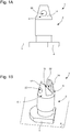
- the peak 2 comprises a base 4 which extends in a plane P on which stand a first arm 6 and a second arm 8 which are free at their end opposite to the base 4.
- the first and second arms 6 and 8 extend perpendicularly to the plane P of the base 4 and are separated from each other by a substantially parallelepipedal gap 10.
- the stud 2 is provided with a stop means provided to prevent a glue pad 16 in which is trapped a free end 18 of a last turn on the outside of a spiral spring 20 to escape from the gap 10 in the case where the glue pad 16 separates from the piton 2.
- this stop means is in the form of a hole 22 pierced right through in at least one of the first and second arms 6, 8. In the example illustrated in FIGS. Figures 1A, 1B a hole 22 is drilled in each of the two arms 6 and 8.
- spiral spring 20 made of silicon more particularly visible on the Figures 6A and 6B is conventionally made of a very thin spring wound in concentric turns and whose section is constant over substantially its entire length.
- This spiral spring 20 is fixed via a free end 24 of a first turn inside to a balance shaft of the watch movement (not shown) for example by means of a ferrule 28, and via the free end 18 of its last turn outside at piton 2 according to the invention.
- the last turn outside the spiral spring 20 slightly thicker than the other turns over part of its length, can be provided at its free end 18 with a plate 30 made in one piece with the spiral spring 20.
- the presence of the wafer 30 is dictated by considerations specific to the technique of manufacturing spiral springs 20 in silicon only. It is important to understand that the presence of this plate 30 is not made necessary by the needs of the present invention and that it is quite possible to fix a spiral spring without such a plate on the stud 2 according to the invention.
- a hole 22 is pierced right through each of the two arms 6 and 8.
- the liquid adhesive when the liquid adhesive is deposited in the gap 10, the latter diffuses into the holes 22 by capillarity, holes 22 in which the liquid glue will remain trapped and harden after exposure by means of UV radiation or in contact with air. It thus forms an adhesive pad 16 in which the free end 18 of the last turn outside the spiral spring 20 is found imprisoned. Therefore, if, during the life of the glue pad 16 comes to separate or peel off the piton 2, it will not succeed however in disengaging itself from the gap 10 in which it is housed and decoupled from the piton 2 according to the invention, so that it will not interfere with the operation of the watch movement. Indeed, the glue pad 16 will not be able to disengage from the gap 10, especially in the region where the liquid glue has hardened in the holes 22.
- FIGS. FIGS. 2A to 2C Designated as a whole by the general numerical reference 36, a second particular embodiment of a stud 2 according to the invention is shown in FIGS. FIGS. 2A to 2C annexed to this patent application.
- a groove 38 which extends in a plane which forms an angle with the plane P of the base 4 is machined in at least one of the first and second arms 6, 8.
- a groove 38 is machined in the two arms 6 and 8 and extends in a plane perpendicular to the plane P of the base.
- the groove 38 defines for each of the first and second arms 6 and 8 a hook 40 which, once the glue pad 16 cured for example by exposure by means of UV radiation or in contact with the air, will retain the resulting glue pad 16 and prevent it from emerging from the gap 10 in the case where the glue pad 16 disengages the pin 2.
- the hooks 40 form two bearing surfaces 42 on which the liquid adhesive will be deposited by capillarity before curing to form the adhesive pad 16 and which will prevent any possible withdrawal of the adhesive pad 16.
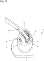
- the 2D figure is a view similar to those of FIGS. 2A to 2C on which we see the spiral spring 20 in silicon fixed on the stud 2 by the free end 18 of its last turn outside by means of an adhesive pad 16.
- FIG. figure 3A Designated as a whole by the general numerical reference 44, a third particular embodiment of a stud 2 according to the invention is shown in FIG. figure 3A attached to this patent application.
- the stop means protrudes into the gap 10 provided for receiving the hardened adhesive pad 16 in which the free end 18 of the last turn is trapped.
- the stop means is in the form of a bead 46 coming from a material with each of the inner lateral surfaces 48 facing each other from the first and second ends. second arm 6 and 8.
- the figure 3B is a view similar to that of the figure 3A on which we see the spiral spring 20 silicon fixed by the free end 18 of its last turn outside on the stud 2 by means of an adhesive pad 16.
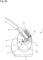
- FIGS. Figures 4A and 4B A possible technique for making the beads 46 is illustrated in FIGS. Figures 4A and 4B .
- This technique consists in providing a stud 2 having a gap 10 whose initial width is d1 , then introducing into this gap 10 a stamping tool 50 whose width d2 is greater than the width d1 and corresponds to the final width of the gap 10 sought. Forcing the stamping tool 50 in the gap 10, the material is forced back and is created on each of the inner side surfaces 48 of the first and second arms 6, 8 a bead 46.
- the beads 46 correspond to a preferred but non-limiting embodiment of the invention. Indeed, to obtain a stop means projecting into the gap 10, it can also be envisaged, for example, to pierce through at least one of the two arms 6, 8, and then introduce into the hole thus obtained a pin which projects into the gap 10.
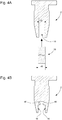
- FIGS. Figures 5A to 5D Another possible technique for creating an annular flange 52 is illustrated in FIGS. Figures 5A to 5D .
- This technique consists in providing a stud 2 having a gap 10, then introducing into this gap 10 a drilling tool 54 whose end is conical. By advancing the drilling tool 54 in the gap 10 from the free end of the arms 6, 8 to the base 4, a first hole 56 is created in the bolt 2 ( Figure 5A ). Conversely, a second hole 58 is machined in the stud 2 from the base 4 towards the free end of the first and second arms 6, 8 ( Figure 5B ).
- the machining is carried out so that the second hole 58 partially opens into the first hole 56, while retaining locally an annular flange 52 on the inner lateral surfaces 48 of the first and second arms 6 and 8 ( Figure 5C ).
- the latter is hardened so as to form a glue pad 16 ( Figure 6D ).
- the glue stud 16 thus formed is retained by the annular collar 52, so that even if the stud 16 is detached from the stud 2, it will be retained inside the gap 10 from which it can not escape. .
- This drop of liquid adhesive 32 is for example deposited by means of a dispensing device 60 automated such as a syringe still known by its English name "dispenser".
- a dispensing device 60 automated such as a syringe still known by its English name "dispenser”.
- the exposure of the drop of liquid glue 32 to ultraviolet light allows its polymerization and its complete hardening.
- the example of the polymerizable liquid glue by exposure to ultraviolet light is given by way of example only, and that other types of liquid glues such as a glue hardening in contact with the air can be envisaged. .
Abstract
L'invention concerne un piton pour la fixation d'une extrémité libre (18) d'une dernière spire à l'extérieur d'un ressort spiral (20) pour un mouvement d'horlogerie, ce piton (2) comprenant une embase (4) qui s'étend dans un plan (P) sur lequel se dressent un premier bras (6) et un second bras (8) qui sont libres à leur extrémité opposée à l'embase (4), le premier et le second bras (6, 8) étant séparés l'un de l'autre par un interstice (10) dans lequel est logée l'extrémité libre (18) de la dernière spire à l'extérieur du ressort spiral (20) qui est emprisonnée dans un plot de colle (16) durcie, l'un au moins des premier et second bras (6, 8) étant muni d'un moyen d'arrêtage agencé pour empêcher le plot de colle (16) dans lequel est emprisonnée l'extrémité libre (18) de la dernière spire à l'extérieur du ressort spiral (20) de se dégager de l'interstice (10) dans lequel il est logé lorsque ce plot de colle (16) n'adhère plus au piton (2).L'invention concerne également un procédé de fabrication d'un tel piton.The invention relates to a stud for fixing a free end (18) of a last turn outside of a spiral spring (20) for a watch movement, this stud (2) comprising a base ( 4) which extends in a plane (P) on which stand a first arm (6) and a second arm (8) which are free at their end opposite the base (4), the first and the second arm (6, 8) being separated from each other by a gap (10) in which is housed the free end (18) of the last turn outside the spiral spring (20) which is trapped in a hardened adhesive pad (16), at least one of the first and second arms (6, 8) being provided with a stop means arranged to prevent the glue pad (16) in which the free end is trapped. (18) of the last turn outside the spiral spring (20) to disengage the gap (10) in which it is housed when the glue pad (16) no longer adheres to the stud (2). The invention There is also a process for manufacturing such a piton.
Description
La présente invention concerne un piton pour la fixation d'un ressort spiral d'un mouvement d'horlogerie. Plus précisément, la présente invention concerne un piton dans lequel une dernière spire à l'extérieur d'un ressort spiral d'un mouvement d'horlogerie est fixée par collage. L'invention concerne également un procédé de fabrication d'un tel piton.The present invention relates to a peg for fixing a spiral spring of a clockwork movement. More specifically, the present invention relates to a pin in which a last turn outside of a spiral spring of a watch movement is fixed by gluing. The invention also relates to a method of manufacturing such a piton.
Dans le domaine de l'horlogerie, un ressort spiral associé à un balancier forme une base de temps pour les pièces d'horlogerie mécaniques. En première approche, le ressort spiral se présente sous la forme d'un très fin ressort enroulé en spires concentriques. Une première extrémité du ressort spiral, appelée première spire à l'intérieur, est fixée à une virole, et une seconde extrémité du ressort spiral, appelée dernière spire à l'extérieur, est fixée à un piton.In the field of watchmaking, a spiral spring associated with a pendulum forms a timebase for mechanical timepieces. At first approach, the spiral spring is in the form of a very thin spring wound in concentric turns. A first end of the spiral spring, called the first turn inside, is attached to a shell, and a second end of the spiral spring, called the last turn outside, is fixed to a peak.
Plus précisément, la base de temps pour les pièces d'horlogerie mécaniques, encore appelée système oscillant, comprend un couple balancier-ressort spiral et un échappement. Le balancier se compose d'un axe de balancier pivoté entre un premier et un second palier et relié à une serge de balancier au moyen de bras radiaux. Le ressort spiral est fixé via sa première spire à l'intérieur à l'axe du balancier par exemple au moyen d'une virole. Le ressort spiral est fixé via sa dernière spire à l'extérieur à un point d'attache formé par un piton porté par un porte-piton le cas échéant. L'échappement, quant à lui, comprend un système de double plateau constitué d'un grand plateau qui porte une cheville de plateau et d'un petit plateau dans lequel est ménagée une encoche. L'échappement comprend également une ancre dont un axe d'ancre est pivoté entre un premier et un second palier. L'ancre se compose d'une baguette qui relie une fourchette à un bras d'entrée et à un bras de sortie. La fourchette est constituée d'une corne d'entrée et d'une corne de sortie entre lesquelles s'étend un dard. Le débattement de la fourchette est limité par une goupille de limitation d'entrée et une goupille de limitation de sortie qui peuvent être faites d'un seul tenant avec un pont d'ancre. Le bras d'entrée et le bras de sortie portent respectivement une palette d'entrée et une palette de sortie. Enfin, l'ancre coopère avec une roue d'échappement comprenant un axe de roue d'échappement pivoté entre un premier et un second palier.More precisely, the time base for the mechanical timepieces, also called the oscillating system, comprises a spring balance-spring pair and an escapement. The balance consists of a balance shaft pivoted between a first and a second bearing and connected to a balance beam by means of radial arms. The spiral spring is fixed via its first turn inside to the axis of the beam for example by means of a ferrule. The spiral spring is fixed via its last turn to the outside at a point of attachment formed by a pin carried by a bolt carrier if necessary. The escapement, meanwhile, includes a double tray system consisting of a large plate that carries a plateau pin and a small plate in which is formed a notch. The escapement also includes an anchor with an anchor axis pivoted between a first and a second bearing. The anchor consists of a rod that connects a fork to an input arm and an output arm. The fork consists of an entrance horn and an exit horn between which a dart extends. The travel of the fork is limited by an entry limiting pin and an output limiting pin that can be made in one piece with an anchor bridge. The inlet arm and the output arm respectively carry an entry pallet and an exit pallet. Finally, the anchor cooperates with an escape wheel comprising an exhaust wheel axle pivoted between a first and a second bearing.
Le ressort spiral prend la forme d'une spirale Enroulé dans un plan horizontal, parallèle au plan du mouvement d'horlogerie, il ne sert qu'une fonction : une fois associé à un balancier, il doit tourner dans un sens, puis dans l'autre, c'est-à-dire osciller autour de sa position d'équilibre à une fréquence la plus constante possible. On dit que le ressort spiral respire. Or, tout contribue à empêcher un ressort spiral d'osciller toujours à la même fréquence. Le ressort spiral doit notamment résister à l'oxydation et au magnétisme qui collent les spires entre elles et arrêtent la montre. L'influence de la pression atmosphérique, par contre, est faible. Longtemps, c'est la température qui a été le coeur du problème, car la chaleur dilate le métal, tandis que le froid le rétrécit. Le ressort spiral doit aussi être élastique pour se déformer et cependant toujours retrouver sa forme.The spiral spring takes the form of a spiral Worn in a horizontal plane, parallel to the plane of the clockwork movement, it only serves a function: once associated with a pendulum, it must turn in one direction, then in the other, that is, oscillate around its equilibrium position at the most constant frequency possible. It is said that the spiral spring breathes. Now, everything helps to prevent a spiral spring from always oscillating at the same frequency. The spiral spring must in particular withstand the oxidation and magnetism that stick the turns together and stop the watch. The influence of atmospheric pressure, on the other hand, is weak. For a long time, it was the temperature that was the heart of the problem, because the heat expands the metal, while the cold shrinks it. The spiral spring must also be elastic to deform and yet still find its shape.
Le matériau utilisé pour la réalisation des ressorts spiraux est habituellement un acier. Ductile, un tel alliage doit résister à la corrosion. Des développements récents proposent de réaliser les ressorts spiraux en silicium. Les spiraux en silicium, notamment parce qu'ils sont insensibles au magnétisme, sont plus précis que leurs prédécesseurs en acier. Par contre, leur prix de revient est plus élevé et ils sont plus difficiles à assembler.The material used for making the spiral springs is usually a steel. Ductile, such an alloy must resist corrosion. Recent developments propose to make the spiral springs in silicon. Silicone spirals, especially because they are insensitive to magnetism, are more accurate than their predecessors in steel. By cons, their cost is higher and they are more difficult to assemble.
Un ressort spiral doit être isochrone. Peu importe jusqu'à quel point le ressort spiral tourne, il doit toujours mettre le même temps à osciller. Si le ressort spiral se contracte de quelques degrés seulement, il accumule peu d'énergie et revient lentement à sa position d'équilibre. Si le ressort spiral est écarté de beaucoup de sa position d'équilibre, il part très vite en sens inverse. L'important est que ces deux déplacements se fassent dans la même durée. L'idée sous-jacente est que l'énergie dont dispose le ressort spiral n'est pas constante et qu'il doit malgré tout fonctionner que la montre soit remontée à fond ou qu'elle soit dans ses dernières heures de réserve de marche.A spiral spring must be isochronous. No matter how far the spiral spring turns, it must always be the same time to oscillate. If the spiral spring contracts a few degrees only, it accumulates little energy and slowly returns to its equilibrium position. If the spiral spring is far from its equilibrium position, it goes very quickly in the opposite direction. The important thing is that these two trips are made in the same duration. The underlying idea is that the energy available to the spiral spring is not constant and it must still work whether the watch is fully up or is in its last hours of power reserve.
En raison de leurs faibles dimensions, les ressorts spiraux sont difficiles à assembler. Or, la façon dont les deux extrémités d'un ressort spiral sont fixées influe également beaucoup sur la précision de la marche du mouvement d'horlogerie. Dans la plupart des mouvements d'horlogerie mécaniques, les deux extrémités du ressort spiral sont insérées dans une pièce percée et sont immobilisées au moyen d'une goupille montée en force manuellement à l'aide d'une pince. Il peut alors se produire une légère rotation du ressort spiral, ce qui est préjudiciable à la précision de la marche du mouvement. Pour palier ce problème, la manufacture horlogère française Lip a, dans les années 1960, proposé de coller un ressort spiral avec un grain de colle thermo-fusible, c'est-à-dire une colle dure à température ambiante, mais fondant sous l'action de la chaleur.Due to their small dimensions, spiral springs are difficult to assemble. However, the way in which the two ends of a spiral spring are fixed also has a great influence on the accuracy of the movement of the watch movement. In most mechanical watch movements, both ends of the spiral spring are inserted into a pierced part and are immobilized by means of a pin mounted manually by force with a clamp. It can then occur a slight rotation of the spiral spring, which is detrimental to the accuracy of the movement. To overcome this problem, the French watch manufacturer Lip, in the 1960s, proposed to stick a spiral spring with a grain of hot-melt glue, that is to say a hard glue at room temperature, but melting under the action of heat.
Néanmoins, même la technique consistant à coller l'extrémité des ressorts spiraux au moyen d'une colle thermo-fusible a montré ses limites. Il a en effet été observé qu'en raison de sa viscosité, la colle thermo-fusible, en fondant, exerce par capillarité une force de traction sur le ressort spiral et peut plaquer l'extrémité du ressort spiral contre les parois du piton dans lequel cette extrémité est engagée. La déformation résultante du ressort spiral induit dans celui-ci des contraintes mécaniques qui sont très préjudiciables à la régularité de sa marche.Nevertheless, even the technique of sticking the end of the spiral springs by means of a hot-melt glue has shown its limits. It has indeed been observed that because of its viscosity, the hot-melt adhesive, by melting, exerts a pulling force by capillarity on the spiral spring and can press the end of the spiral spring against the walls of the stud in which this end is engaged. The resulting deformation of the spiral spring induces in it mechanical stresses which are very detrimental to the regularity of its operation.
Pour remédier à ces problèmes, la Demanderesse a déjà proposé un procédé de fixation d'un ressort spiral qui n'induise pas de contrainte mécanique dans un tel ressort spiral et ne l'écarte pas de sa position de repos. Ce procédé consiste à coller la dernière spire à l'extérieur d'un ressort spiral dans un piton au moyen d'une goutte de colle fluide polymérisable par exemple au moyen d'un rayonnement ultraviolet. Ainsi, même si, au moment du dépôt de la goutte de colle, par exemple au moyen d'un distributeur de colle du type seringue, l'extrémité libre de la dernière spire du spiral se déplace un peu sous l'effet du poids de la goutte colle, ce qui induit dans le ressort spiral des contraintes mécaniques non désirées, la colle est, avant durcissement, suffisamment fluide pour permettre à l'extrémité libre de la dernière spire du spiral de retrouver spontanément sa position de repos. Les contraintes mécaniques induites dans le ressort spiral au moment du dépôt de la goutte de colle liquide disparaissent donc d'elles-mêmes, de sorte que la régularité de la marche du ressort spiral n'est pas affectée par l'opération de collage de ce dernier.To remedy these problems, the Applicant has already proposed a method of fixing a spiral spring which does not induce mechanical stress in such a spiral spring and does not separate it from its rest position. This method consists in bonding the last turn outside of a spiral spring in a peak by means of a drop of fluid polymerizable glue for example by means of ultraviolet radiation. Thus, even if, at the time of depositing the drop of glue, for example by means of a glue dispenser of the syringe type, the free end of the last turn of the spiral moves a little under the effect of the weight of the glue drip, which induces in the spiral spring unwanted mechanical stresses, the glue is, before curing, sufficiently fluid to allow the free end of the last spiral coil to spontaneously return to its rest position. The mechanical stresses induced in the spiral spring at the time of deposition of the liquid glue drop therefore disappear by themselves, so that the regularity of the spiral spring step is not affected by the bonding operation of this latest.
La solution ci-dessus permet ainsi de fixer un ressort spiral par l'extrémité libre de sa dernière spire à l'extérieur dans un piton en éliminant totalement ou du moins pour la plus grande part les contraintes mécaniques qui sont habituellement induites dans un tel ressort spiral lors de son montage. La régularité de marche du ressort spiral en est ainsi grandement améliorée. A l'usage, la Demanderesse s'est néanmoins rendu compte que le plot de colle durcie formé lorsque l'on polymérise la goutte de colle liquide dont on se sert pour fixer l'extrémité libre de la dernière spire à l'extérieur du ressort spiral avait parfois tendance à se désolidariser du piton, ce qui, bien sûr, entraîne la panne immédiate du mouvement d'horlogerie dans lequel est installé ce ressort spiral. Une telle situation dans laquelle le bloc de colle dans lequel est emprisonnée l'extrémité libre de la dernière spire à l'extérieur du ressort spiral se détache du piton est notamment due à des problèmes d'état de surface du piton qui empêchent le plot de colle d'adhérer parfaitement au piton.The above solution thus makes it possible to fix a spiral spring by the free end of its last turn outside in a peak by completely eliminating or at least for the most part the mechanical stresses which are usually induced in such a spring. spiral during its assembly. The smooth running of the spiral spring is thus greatly improved. In use, the Applicant has nevertheless realized that the hardened glue pad formed when the liquid glue drop is polymerized which is used to fix the free end of the last turn outside the spring spiral sometimes had a tendency to separate from the peak, which, of course, results in the immediate failure of the watch movement in which the spiral spring is installed. Such a situation in which the adhesive block in which the free end of the last turn outside the spiral spring is trapped is detached from the peak is notably due to piton surface state problems which prevent the stud from glue to adhere perfectly to the piton.
La présente invention a pour but de résoudre les problèmes mentionnés ci-avant ainsi que d'autres encore en procurant un nouveau type de piton dont la géométrie permet de garantir que le plot de colle dans lequel est emprisonnée l'extrémité libre de la dernière spire à l'extérieur du ressort spiral ne se dissociera pas du piton même si ce plot de colle n'adhère plus au piton.The present invention aims to solve the problems mentioned above as well as others by providing a new type of stud whose geometry ensures that the glue pad in which is trapped the free end of the last turn outside the spiral spring will not dissociate piton even if this pad of glue no longer adheres to the peak.
A cet effet, la présente invention concerne un piton utilisé pour fixer une extrémité libre d'une dernière spire à l'extérieur d'un ressort spiral pour un mouvement d'horlogerie, ce piton comprenant une embase qui s'étend dans un plan et sur lequel se dressent un premier bras et un second bras qui sont libres à leur extrémité opposée à l'embase, le premier et le second bras étant séparés l'un de l'autre par un interstice dans lequel est logée l'extrémité libre de la dernière spire à l'extérieur du ressort spiral qui est emprisonnée dans un plot de colle durcie, l'un au moins des premier et second bras étant muni d'un moyen d'arrêtage agencé pour empêcher le plot de colle dans lequel est emprisonnée l'extrémité libre de la dernière spire à l'extérieur du ressort spiral de se dégager de l'interstice dans lequel il est logé lorsque ce plot de colle n'adhère plus au piton.To this end, the present invention relates to a stud used to fix a free end of a last turn outside of a spiral spring for a watch movement, this stud comprising a base which extends in a plane and on which stands a first arm and a second arm which are free at their opposite end to the base, the first and second arms being separated from each other by a gap in which is housed the free end of the last turn outside the spiral spring which is trapped in a hardened glue pad, at least one of the first and second arms being provided with a stop means arranged to prevent the stick of glue in which is trapped the free end of the last turn outside the spiral spring to disengage the gap in which it is housed when the glue pad no longer adheres to the peak.
Selon une forme particulière d'exécution de l'invention, l'un au moins des premier et second bras est percé de part en part d'un trou.According to a particular embodiment of the invention, at least one of the first and second arms is pierced through a hole.
Selon une autre forme particulière d'exécution de l'invention, au moins le premier bras est libre à son extrémité opposée à l'embase, et il comprend une rainure à distance de son extrémité libre, cette rainure s'étendant dans un plan qui forme un angle avec le plan de l'embase.According to another particular embodiment of the invention, at least the first arm is free at its end opposite the base, and it comprises a groove at a distance from its free end, this groove extending in a plane which forms an angle with the plane of the base.
Selon encore une autre forme particulière d'exécution de l'invention, le moyen d'arrêtage fait saillie dans l'interstice prévu pour recevoir le plot de colle durcie dans lequel est emprisonnée l'extrémité libre de la dernière spire à l'extérieur du ressort spiral.According to yet another particular embodiment of the invention, the stop means protrudes into the gap intended to receive the hardened glue pad in which is trapped the free end of the last turn outside the spiral spring.
Selon encore une autre forme particulière d'exécution de l'invention, le moyen d'arrêtage est au moins un bourrelet qui est fait de matière avec le bras correspondant du piton.According to yet another particular embodiment of the invention, the stop means is at least one bead which is made of material with the corresponding arm of the piton.
Grâce à ces caractéristiques, la présente invention procure un piton utilisé pour fixer l'extrémité libre de la dernière spire à l'extérieur d'un ressort spiral pour un mouvement d'horlogerie, ce piton étant pourvu d'un moyen d'arrêtage prévu pour empêcher le plot de colle dans lequel est emprisonnée l'extrémité libre de la dernière spire à l'extérieur du ressort spiral de se dégager de l'interstice dans lequel est logé ce plot lorsque ce dernier n'adhère plus au piton.Thanks to these features, the present invention provides a stud used to fix the free end of the last turn outside of a spiral spring for a watch movement, this pin being provided with a stop means provided to prevent the stick of adhesive in which is trapped the free end of the last turn outside the spiral spring to disengage the gap in which is housed this stud when it no longer adheres to the peak.
La présente invention s'applique à tous les types de ressorts spiraux connus. Il peut notamment s'agir des spiraux métalliques typiquement réalisés en acier. Il peut également s'agir des ressorts spiraux réalisés en silicium.The present invention applies to all types of known spiral springs. It may especially be metal spirals typically made of steel. It can also be spiral springs made of silicon.
La présente invention n'est également pas non plus limitée à un type de colle en particulier. En effet, l'extrémité libre de la dernière spire à l'extérieur du ressort spiral peut par exemple être collée dans l'interstice du piton au moyen de l'adhésif bien connu sous sa dénomination « gomme laque » (adhésif connu sous le même nom ou sous le nom « shellac » en terminologie anglo-saxonne), ou bien être collée au moyen d'une colle liquide pouvant, par exemple, être polymérisée au moyen d'un rayonnement UV. L'avantage de la gomme laque réside essentiellement dans le fait qu'elle adhère bien et durablement au piton. Par contre, à la connaissance de la Demanderesse, le collage des spiraux sur les pitons au moyen de gomme laque n'a jamais pu être automatisé et sa réussite reste entièrement dépendante de la dextérité de l'opérateur ou de l'opératrice chargé de cette opération. La gomme laque est une résine et l'opérateur en prélève un petit copeau qu'il place dans l'interstice destiné à recevoir l'extrémité libre de la dernière spire extérieure du ressort spiral. Après avoir placé cette extrémité du ressort spiral dans l'interstice du piton, l'opérateur chauffe brièvement le copeau de gomme laque qui fond et emprisonne l'extrémité libre de la dernière spire extérieure du ressort spiral. L'opérateur laisse ensuite la gomme laque refroidir et, après contrôle visuel, décide s'il faut rajouter une quantité de gomme laque supplémentaire ou bien s'il peut passer à l'ensemble ressort spiral/piton suivant. On comprend qu'une telle succession d'opérations est difficile à automatiser. C'est pourquoi il a été proposé de coller les ressorts spiraux, notamment ceux réalisés en silicium, au moyen d'une colle liquide polymérisable à l'aide d'un rayonnement UV ou bien apte à durcir au contact de l'air. Comme déjà mentionné ci-dessus, la fluidité d'un tel type de colle est telle qu'après dépôt d'une goutte de cette colle, l'extrémité libre de la dernière spire extérieure du ressort spiral peut revenir spontanément à sa position de repos dont elle a été écartée lors du dépôt de la colle. Surtout, la quantité de colle liquide déposée peut être contrôlée de manière très précise et entièrement automatisée à l'aide d'un distributeur de colle tel qu'une seringue encore connu sous sa dénomination anglo-saxonne « dispenser ». Après dépôt de la goutte de colle liquide, celle-ci est durcie par insolation au moyen d'une lampe UV. On comprend bien qu'un tel procédé est aisément automatisable. Par contre, l'inconvénient de la colle photo-polymérisable est que son adhérence au piton n'est pas très satisfaisante et que les risques que le plot de colle dans lequel l'extrémité libre de la dernière spire à l'extérieur du ressort spiral est emprisonnée se détache du piton sont élevés.The present invention is also not limited to any particular type of glue. Indeed, the free end of the last turn outside of the spiral spring may for example be glued into the gap of the peak by means of the adhesive well known under the name "shellac" (known adhesive under the same name or under the name "shellac" in English terminology), or be glued by means of a liquid adhesive that can, for example, be polymerized by means of UV radiation. The advantage of shellac lies essentially in the fact that it adheres well and durably to the piton. On the other hand, to the knowledge of the Applicant, the gluing of the spirals on the studs using shellac has never been automated and its success remains entirely dependent on the dexterity of the operator or the operator in charge of this task. surgery. The shellac is a resin and the operator takes a small chip that places in the gap to receive the free end of the last outer turn of the spiral spring. After placing this end of the spiral spring in the gap of the peak, the operator briefly heats the shellac shell which melts and traps the free end of the last outer turn of the spiral spring. The operator then allows the shellac to cool down and, after visual inspection, decides whether to add an additional quantity of shellac or whether it can pass to the next spiral spring / bolt assembly. It is understood that such a succession of operations is difficult to automate. That is why it has been proposed to bond the spiral springs, especially those made of silicon, by means of a liquid glue polymerizable with UV radiation or able to harden in contact with the air. As already mentioned above, the fluidity of such a type of glue is such that after depositing a drop of this glue, the free end of the last outer turn of the spiral spring can return spontaneously to its rest position. from which it was discarded during the deposit of the glue. Above all, the amount of liquid glue deposited can be controlled very accurately and fully automated with the aid of a glue dispenser such as a syringe also known by its English name "dispenser". After depositing the drop of liquid glue, it is cured by insolation by means of a UV lamp. It is well understood that such a method is easily automatable. On the other hand, the disadvantage of the photo-polymerizable glue is that its adhesion to the piton is not very satisfactory and that the risks that the glue pad in which the free end of the last turn on the outside of the spiral spring is imprisoned stands out from the peak are raised.
C'est pour répondre à ces problèmes que la présente invention propose de munir un piton d'horlogerie d'un moyen d'arrêtage pour empêcher le plot de colle dans lequel est emprisonnée l'extrémité libre de la dernière spire à l'extérieur du ressort spiral de se détacher de ce piton. Le piton se présente typiquement sous la forme d'une embase qui s'étend dans un plan à partir duquel deux bras séparés l'un de l'autre par un interstice prévu pour recevoir l'extrémité libre de la dernière spire à l'extérieur s'étendent. Le moyen d'arrêtage peut prendre des formes variées parmi lesquelles on peut citer de manière non limitative un trou qui traverse de part en part l'un au moins des deux bras. Une fois l'extrémité libre de la dernière spire à l'extérieur du ressort spiral positionnée dans l'interstice du piton, on dépose la goutte de colle liquide. Par capillarité, celle-ci va notamment diffuser dans le trou dans lequel elle va rester prisonnière et durcir après insolation au moyen d'un rayonnement UV. Par conséquent, si, en cours de vie, le plot de colle vient à se désolidariser du piton, il ne parviendra toutefois pas à se dégager de l'interstice dans lequel il est logé, de sorte que cela ne se ressentira pas sur le fonctionnement du mouvement d'horlogerie.It is to answer these problems that the present invention proposes to provide a stop watch with a stop means to prevent the glue pad in which is trapped the free end of the last turn outside the spiral spring to detach from this piton. The pin is typically in the form of a base which extends in a plane from which two arms separated from each other by a gap designed to receive the free end of the last turn outside. extend. The stop means may take various forms, among which may be mentioned in a nonlimiting manner a hole which passes right through at least one of the two arms. Once the free end of the last turn outside the spiral spring positioned in the gap of piton, we drop the drop of liquid glue. By capillarity, it will notably diffuse into the hole in which it will remain trapped and harden after exposure by means of UV radiation. Therefore, if in the course of life, the glue pad is to separate from the piton, it will not manage to escape the gap in which it is housed, so that it will not feel on the operation of the watch movement.
Le moyen d'arrêtage peut aussi être prévu sous la forme d'un élément, par exemple un bourrelet, faisant saillie dans l'interstice du piton dans lequel est logée l'extrémité libre de la dernière spire à l'extérieur du ressort spiral. Dans ce cas aussi, si le plot de colle dans lequel est emprisonnée l'extrémité libre du ressort spiral se désolidarise du piton, ce plot de colle durcie ne pourra s'échapper de l'interstice.The stop means may also be provided in the form of an element, for example a bead protruding into the gap of the stud in which is housed the free end of the last turn outside the spiral spring. In this case too, if the glue pad in which is trapped the free end of the spiral spring disengages the pin, this hardened glue pad can not escape the gap.
Selon encore une autre forme particulière de réalisation de l'invention, l'un au moins des premier et second bras du piton comprend une rainure qui s'étend dans un plan qui forme un angle avec le plan de l'embase. Cette rainure délimite un crochet qui fait office de moyen d'arrêtage du plot de colle.According to yet another particular embodiment of the invention, at least one of the first and second arms of the stud comprises a groove which extends in a plane which forms an angle with the plane of the base. This groove defines a hook which serves as a means of stopping the glue pad.
L'invention concerne également un procédé de fabrication d'un piton utilisé pour la fixation d'une extrémité libre d'une dernière spire à l'extérieur d'un ressort spiral pour un mouvement d'horlogerie, ce piton comprenant une embase qui s'étend dans un plan et un premier et un second bras qui s'étendent à partir de ce plan, le premier et le second bras étant séparés l'un de l'autre par un interstice dans lequel est logée l'extrémité libre de la dernière spire à l'extérieur du ressort spiral qui est emprisonnée dans un plot de colle durcie, l'interstice étant initialement réalisé avec une première largeur, le procédé comprenant l'étape qui consiste à élargir l'interstice par étampage et à créer par refoulement de matière un moyen d'arrêtage qui fait saillie dans l'interstice prévu pour recevoir le plot de colle durcie dans lequel est emprisonnée l'extrémité libre de la dernière spire à l'extérieur du ressort spiral.The invention also relates to a method of manufacturing a pin used for fixing a free end of a last turn outside of a spiral spring for a watch movement, this peak comprising a base which is extends in a plane and a first and a second arm extending from this plane, the first and second arms being separated from each other by a gap in which is housed the free end of the last turn outside the spiral spring which is trapped in a hardened glue pad, the gap being initially formed with a first width, the method comprising the step of expanding the gap by stamping and creating by pushing back of material a stopping means which protrudes into the gap provided to receive the hardened glue pad in which is trapped the free end of the last turn outside the spiral spring.
D'autres caractéristiques et avantages de la présente invention ressortiront plus clairement de la description détaillée qui suit d'un exemple de réalisation d'un piton selon l'invention, cet exemple étant donné à titre purement illustratif et non limitatif seulement en liaison avec le dessin annexé sur lequel :
- les
figures 1A et 1B sont des vues respectivement en élévation et en perspective d'une première forme d'exécution de l'invention dans laquelle les premier et second bras du piton selon l'invention sont percés d'un trou de part en part ; - la
figure 1C est une vue analogue à celle de lafigure 1B sur laquelle on voit un ressort spiral en silicium dont l'extrémité libre de la dernière spire à l'extérieur est fixée sur le piton au moyen d'un plot de colle ; - les
figures 2A, 2B et 2C sont des vues en élévation et en perspective d'une deuxième forme d'exécution de l'invention dans laquelle une rainure usinée dans les premier et second bras du piton selon l'invention délimite deux crochets ; - la
figure 2D est une vue analogue à celle de lafigure 2C sur laquelle on voit un ressort spiral en silicium dont l'extrémité libre de la dernière spire à l'extérieur est fixée sur le piton au moyen d'un plot de colle ; - la
figure 3A est une vue en perspective d'une troisième forme d'exécution de l'invention dans laquelle un bourrelet ménagé sur chacune des surfaces latérales internes en regard des premier et second bras du piton selon l'invention fait saillie dans l'interstice ; - la
figure 3B est une vue analogue à celle de lafigure 3A sur laquelle on voit un ressort spiral en silicium dont l'extrémité libre de la dernière spire à l'extérieur est fixée sur le piton au moyen d'un plot de colle ; - les
figures 4A et 4B illustrent schématiquement une première variante du procédé d'usinage des bourrelets sur les surfaces latérales internes en regard des premier et second bras du piton ; - les
figures 5A à 5D illustrent schématiquement une seconde variante du procédé d'usinage des bourrelets sur les surfaces latérales internes en regard des premier et second bras du piton, et - les
figures 6A et 6B illustrent schématiquement le procédé de collage de l'extrémité libre de la dernière spire à l'extérieur d'un ressort spiral sur le piton au moyen d'un plot de colle.
- the
Figures 1A and 1B are views respectively in elevation and in perspective of a first embodiment of the invention in which the first and second arms of the stud according to the invention are pierced with a hole from one side; - the
figure 1C is a view similar to that of theFigure 1B on which we see a silicon spiral spring whose free end of the last turn to the outside is fixed on the peak by means of a pad of glue; - the
FIGS. 2A, 2B and 2C are views in elevation and in perspective of a second embodiment of the invention in which a groove machined in the first and second arms of the stud according to the invention defines two hooks; - the
2D figure is a view similar to that of theFigure 2C on which we see a silicon spiral spring whose free end of the last turn to the outside is fixed on the peak by means of a pad of glue; - the
figure 3A is a perspective view of a third embodiment of the invention in which a bead formed on each of the inner side surfaces facing the first and second arms of the stud according to the invention protrudes into the gap; - the
figure 3B is a view similar to that of thefigure 3A on which we see a silicon spiral spring whose free end of the last turn outside is fixed on the peak by means of a glue pad; - the
Figures 4A and 4B schematically illustrate a first variant of the bead machining method on the internal lateral surfaces facing the first and second arms of the stud; - the
Figures 5A to 5D schematically illustrate a second variant of the bead machining method on the internal lateral surfaces facing the first and second arms of the peak, and - the
Figures 6A and 6B schematically illustrate the method of bonding the free end of the last turn to the outside of a spiral spring on the peak by means of a glue pad.
La présente invention procède de l'idée générale inventive qui consiste à munir un piton destiné à la fixation d'un ressort spiral d'un mouvement d'horlogerie d'un moyen d'arrêtage prévu pour empêcher une extrémité libre d'une dernière spire à l'extérieur du ressort spiral de se découpler du piton et de provoquer l'arrêt immédiat du mouvement d'horlogerie. Plus précisément, le piton comprend une embase qui s'étend dans un plan à partir duquel s'étendent un premier et un second bras séparés l'un de l'autre par un interstice. Cet interstice est prévu pour recevoir l'extrémité libre de la dernière spire à l'extérieur du ressort spiral qui va être immobilisée au moyen d'un plot de colle durcie par rayonnement ultraviolet. Conformément à l'invention, l'un au moins des deux bras du piton est muni d'un moyen d'arrêtage prévu pour empêcher le plot de colle, et donc l'extrémité libre de la spire à l'extérieur du ressort spiral, de s'échapper de l'interstice pour le cas où le plot de colle viendrait à se désolidariser du piton. Ce moyen d'arrêtage peut se présenter sous diverses formes telles que, non limitativement, un trou, un bourrelet ou bien encore un crochet.The present invention proceeds from the general inventive idea of providing a stud for fixing a spiral spring of a clockwork movement with a stop means provided to prevent a free end of a last turn. outside the spiral spring to decouple the piton and cause the immediate stop of the watch movement. More specifically, the stud comprises a base which extends in a plane from which extend a first and a second arm separated from one another by a gap. This gap is intended to receive the free end of the last turn outside the spiral spring which will be immobilized by means of a glue pad cured by ultraviolet radiation. According to the invention, at least one of the two arms of the stud is provided with a stop means provided to prevent the glue pad, and therefore the free end of the coil outside the spiral spring, to escape from the gap for the case where the glue post would come to separate from the piton. This stop means can be in various forms such as, not limited to, a hole, a bead or a hook.
Dans la description détaillée qui suit de plusieurs formes particulières d'exécution de l'invention, on s'intéressera au collage d'un spiral en silicium au moyen d'une colle liquide destinée à être polymérisée au moyen d'un rayonnement ultraviolet. On comprendra cependant que l'invention n'est pas limitée à ce mode de réalisation particulier et qu'elle s'applique de manière identique à tout type de ressort spiral comme les ressorts spiraux métalliques réalisés par exemple au moyen d'un alliage d'acier.In the following detailed description of several particular embodiments of the invention, attention will be given to bonding a silicon balance spring by means of a liquid adhesive intended to be polymerized by means of ultraviolet radiation. However, it will be understood that the invention is not limited to this particular embodiment and that it applies identically to any type of spiral spring such as metal spiral springs made for example by means of a metal alloy. steel.
Désignée dans son ensemble par la référence numérique 1, une première forme particulière d'exécution d'un piton 2 conforme à l'invention est représentée aux
Conformément à l'invention, le piton 2 est muni d'un moyen d'arrêtage prévu pour empêcher un plot de colle 16 dans lequel est emprisonnée une extrémité libre 18 d'une dernière spire à l'extérieur d'un ressort spiral 20 de s'échapper de l'interstice 10 dans le cas où le plot de colle 16 se désolidarise du piton 2. Selon la première forme particulière d'exécution de l'invention, ce moyen d'arrêtage se présente sous la forme d'un trou 22 percé de part en part dans l'un au moins des premier et second bras 6, 8. Dans l'exemple illustré aux
L'exemple de ressort spiral 20 en silicium plus particulièrement visible sur les
Dans l'exemple illustré aux
Dans ce qui suit, les éléments identiques à ceux décrits en liaison avec les
Désignée dans son ensemble par la référence numérique générale 36, une deuxième forme particulière d'exécution d'un piton 2 conforme à l'invention est représentée aux
La
Désignée dans son ensemble par la référence numérique générale 44, une troisième forme particulière d'exécution d'un piton 2 selon l'invention est représentée à la
La
Une technique possible pour réaliser les bourrelets 46 est illustrée aux
Une autre technique possible pour créer une collerette annulaire 52 est illustrée aux
Il va de soi que la présente invention n'est pas limitée au mode de réalisation qui vient d'être décrit et que diverses modifications et variantes simples peuvent être envisagées par l'homme du métier sans sortir du cadre de l'invention tel que défini par les revendications annexées. En particulier, en liaison avec les
- 1. Première forme particulière d'exécution1. First particular form of performance
- 2. Piton2. Piton
- 4. Embase4. Base
- P. PlanP. Plan
- 6. Premier bras6. First arm
- 8. Second bras8. Second arm
- 10. Interstice10. Interstice
- 12, 14. Surfaces extérieures12, 14. Outside surfaces
- 16. Plot de colle16. Plot of glue
- 18. Extrémité libre18. Free end
- 20. Ressort spiral20. Spiral spring
- 22. Trou22. Hole
- 24. Extrémité libre24. Free end
- 28. Virole28. Ferrule
- 30. Plaquette30. Plaque
- 32. Goutte de colle32. Drop of glue
- 34. Source de rayonnement ultraviolet34. Source of ultraviolet radiation
- 36. Deuxième forme particulière d'exécution36. Second particular form of performance
- 38. Rainure38. Groove
- 40. Crochets40. Hooks
- 42. Surfaces d'appui42. Support surfaces
- 44. Troisième forme particulière d'exécution44. Third particular form of performance
- 46. Bourrelets46. Beads
- 48. Surfaces latérales internes48. Internal side surfaces
- 50. Outil de matriçage50. Stamping tool
- d1. Largeur initialed1. Initial width
- d2. Largeur finaled2. Final width
- 52. Collerette annulaire52. Rectangular collar
- 54. Outil de perçage54. Drilling tool
- 56. Premier trou56. First hole
- 58. Second trou58. Second hole
- 60. Distributeur de colle60. Glue dispenser
Claims (7)
Priority Applications (4)
| Application Number | Priority Date | Filing Date | Title |
|---|---|---|---|
| EP18172195.2A EP3570118B1 (en) | 2018-05-14 | 2018-05-14 | Pin for attaching a hairspring of a clockwork movement and method for manufacturing such a pin |
| JP2019065797A JP6892888B2 (en) | 2018-05-14 | 2019-03-29 | Balanced spring studs that secure the spiral springs of the timekeeping movement and methods of manufacturing such balanced spring studs. |
| US16/379,009 US11480926B2 (en) | 2018-05-14 | 2019-04-09 | Balance-spring stud for fixing a spiral spring of a timepiece movement and method for manufacturing such a balance-spring stud |
| CN201910393205.3A CN110488592B (en) | 2018-05-14 | 2019-05-13 | Balance spring stud and method for producing a balance spring stud |
Applications Claiming Priority (1)
| Application Number | Priority Date | Filing Date | Title |
|---|---|---|---|
| EP18172195.2A EP3570118B1 (en) | 2018-05-14 | 2018-05-14 | Pin for attaching a hairspring of a clockwork movement and method for manufacturing such a pin |
Publications (2)
| Publication Number | Publication Date |
|---|---|
| EP3570118A1 true EP3570118A1 (en) | 2019-11-20 |
| EP3570118B1 EP3570118B1 (en) | 2022-01-12 |
Family
ID=62167150
Family Applications (1)
| Application Number | Title | Priority Date | Filing Date |
|---|---|---|---|
| EP18172195.2A Active EP3570118B1 (en) | 2018-05-14 | 2018-05-14 | Pin for attaching a hairspring of a clockwork movement and method for manufacturing such a pin |
Country Status (4)
| Country | Link |
|---|---|
| US (1) | US11480926B2 (en) |
| EP (1) | EP3570118B1 (en) |
| JP (1) | JP6892888B2 (en) |
| CN (1) | CN110488592B (en) |
Families Citing this family (1)
| Publication number | Priority date | Publication date | Assignee | Title |
|---|---|---|---|---|
| JP6757481B1 (en) * | 2020-01-29 | 2020-09-16 | セイコーウオッチ株式会社 | Governor, escapement, movement and watch |
Citations (3)
| Publication number | Priority date | Publication date | Assignee | Title |
|---|---|---|---|---|
| FR2051170A5 (en) * | 1969-06-26 | 1971-04-02 | Kienzle Uhrenfabriken Gmbh | |
| FR2352332A1 (en) * | 1975-12-02 | 1977-12-16 | Hormec Sa | Fixing element for end of balance spring - has transverse hole and perpendicular slot extending beyond hole and with glued attachment |
| CH622149GA3 (en) * | 1977-12-23 | 1981-03-31 | Device for fixing the outer end of a hairspring to the framework of the movement of a timepiece and method for manufacturing this device |
Family Cites Families (10)
| Publication number | Priority date | Publication date | Assignee | Title |
|---|---|---|---|---|
| CH499804A (en) * | 1965-04-21 | 1969-04-15 | Virola Sa | Device for fixing a watch balance spring to the balance axis |
| FR2141622B1 (en) * | 1971-06-15 | 1977-06-03 | Lip Horlogerie | |
| CH45273A4 (en) * | 1973-01-12 | 1974-09-13 | ||
| FR2283475A1 (en) * | 1973-12-21 | 1976-03-26 | Epsilon Sarl | Fixing timepiece balance spring to bolt - using fusible material for holding end of spring |
| JPS521172U (en) * | 1975-06-23 | 1977-01-06 | ||
| EP0942337B1 (en) * | 1997-08-28 | 2006-11-15 | Seiko Epson Corporation | Timepiece or music box |
| EP1515200A1 (en) * | 2003-09-10 | 2005-03-16 | Patek Philippe S.A. | Hairspring for timepiece |
| EP3118692B1 (en) * | 2015-07-16 | 2018-12-26 | Nivarox-FAR S.A. | Timepiece hairspring to hairspring-stud attachment by gluing |
| CH711473B1 (en) * | 2016-02-25 | 2017-03-15 | Eta Sa Mft Horlogère Suisse | A method of fixing a hairspring for a mechanical horological movement by means of an adhesive in a piton. |
| EP3432083A1 (en) * | 2016-02-25 | 2019-01-23 | ETA SA Manufacture Horlogère Suisse | Hairspring for mechanical clock movement |
-
2018
- 2018-05-14 EP EP18172195.2A patent/EP3570118B1/en active Active
-
2019
- 2019-03-29 JP JP2019065797A patent/JP6892888B2/en active Active
- 2019-04-09 US US16/379,009 patent/US11480926B2/en active Active
- 2019-05-13 CN CN201910393205.3A patent/CN110488592B/en active Active
Patent Citations (3)
| Publication number | Priority date | Publication date | Assignee | Title |
|---|---|---|---|---|
| FR2051170A5 (en) * | 1969-06-26 | 1971-04-02 | Kienzle Uhrenfabriken Gmbh | |
| FR2352332A1 (en) * | 1975-12-02 | 1977-12-16 | Hormec Sa | Fixing element for end of balance spring - has transverse hole and perpendicular slot extending beyond hole and with glued attachment |
| CH622149GA3 (en) * | 1977-12-23 | 1981-03-31 | Device for fixing the outer end of a hairspring to the framework of the movement of a timepiece and method for manufacturing this device |
Also Published As
| Publication number | Publication date |
|---|---|
| CN110488592A (en) | 2019-11-22 |
| US11480926B2 (en) | 2022-10-25 |
| CN110488592B (en) | 2021-03-16 |
| JP2019200199A (en) | 2019-11-21 |
| JP6892888B2 (en) | 2021-06-23 |
| US20190346812A1 (en) | 2019-11-14 |
| EP3570118B1 (en) | 2022-01-12 |
Similar Documents
| Publication | Publication Date | Title |
|---|---|---|
| EP2196868B1 (en) | Hairspring with curve elevation made from a silicon-based material | |
| EP2184652B1 (en) | Spiral with terminal curve elevation in micro-machinable material | |
| EP1035453B1 (en) | Dial comprising brilliants, applied ornaments or other attached elements and process for fixing such elements onto such a dial | |
| EP3182212B1 (en) | Composite part with resilient means under stress | |
| EP2930571A1 (en) | Horological ensemble using an amorphous metal alloy | |
| EP2206022B1 (en) | Shock-absorbing bearing for timepiece | |
| EP3451076B1 (en) | Stud-holder for a mechanical clockwork movement | |
| EP2469351A1 (en) | Assembly of a part not comprising a plastic range | |
| EP2154582A1 (en) | Gear method for a clock piece | |
| CH714775B1 (en) | Piton for fixing a spiral spring of a watch movement and methods of manufacturing such a stud. | |
| EP3570118B1 (en) | Pin for attaching a hairspring of a clockwork movement and method for manufacturing such a pin | |
| EP3211486B1 (en) | Method for attaching a hairspring for mechanical clock movement | |
| CH710112B1 (en) | Mechanical component, manufacturing process of a mechanical component, movement and timepiece. | |
| EP2107433B1 (en) | Method for assembling a part on an axle | |
| EP2585877B1 (en) | Method for producing a watchmaking component comprising at least two parts | |
| WO2017157540A1 (en) | Hand comprising an end part, and mounting method | |
| CH710113B1 (en) | Mechanical component, manufacturing process of a mechanical component, movement and timepiece. | |
| EP1211578B1 (en) | Assembling by piling a plurality of modules forming an electromagnetic device, in particular for an ultra thin time piece | |
| EP4332686A1 (en) | Hairspring for balance-hairspring assembly of a clock movement | |
| CH719838B1 (en) | Fixing part of a spiral spring of a clock movement. | |
| CH719711B1 (en) | Watch assembly including a spiral spring and a pin | |
| CH704275B1 (en) | Rocking for exhaust dit a constant force one piece of watches. | |
| CH711473B1 (en) | A method of fixing a hairspring for a mechanical horological movement by means of an adhesive in a piton. | |
| CH719999A2 (en) | Spiral of a balance-spring assembly of a mechanical watch movement | |
| CH707884A2 (en) | watch Spiral fragile material. |
Legal Events
| Date | Code | Title | Description |
|---|---|---|---|
| PUAI | Public reference made under article 153(3) epc to a published international application that has entered the european phase |
Free format text: ORIGINAL CODE: 0009012 |
|
| STAA | Information on the status of an ep patent application or granted ep patent |
Free format text: STATUS: THE APPLICATION HAS BEEN PUBLISHED |
|
| AK | Designated contracting states |
Kind code of ref document: A1 Designated state(s): AL AT BE BG CH CY CZ DE DK EE ES FI FR GB GR HR HU IE IS IT LI LT LU LV MC MK MT NL NO PL PT RO RS SE SI SK SM TR |
|
| AX | Request for extension of the european patent |
Extension state: BA ME |
|
| STAA | Information on the status of an ep patent application or granted ep patent |
Free format text: STATUS: REQUEST FOR EXAMINATION WAS MADE |
|
| 17P | Request for examination filed |
Effective date: 20200520 |
|
| RBV | Designated contracting states (corrected) |
Designated state(s): AL AT BE BG CH CY CZ DE DK EE ES FI FR GB GR HR HU IE IS IT LI LT LU LV MC MK MT NL NO PL PT RO RS SE SI SK SM TR |
|
| GRAP | Despatch of communication of intention to grant a patent |
Free format text: ORIGINAL CODE: EPIDOSNIGR1 |
|
| STAA | Information on the status of an ep patent application or granted ep patent |
Free format text: STATUS: GRANT OF PATENT IS INTENDED |
|
| INTG | Intention to grant announced |
Effective date: 20210728 |
|
| GRAS | Grant fee paid |
Free format text: ORIGINAL CODE: EPIDOSNIGR3 |
|
| GRAJ | Information related to disapproval of communication of intention to grant by the applicant or resumption of examination proceedings by the epo deleted |
Free format text: ORIGINAL CODE: EPIDOSDIGR1 |
|
| GRAL | Information related to payment of fee for publishing/printing deleted |
Free format text: ORIGINAL CODE: EPIDOSDIGR3 |
|
| STAA | Information on the status of an ep patent application or granted ep patent |
Free format text: STATUS: REQUEST FOR EXAMINATION WAS MADE |
|
| INTC | Intention to grant announced (deleted) | ||
| GRAP | Despatch of communication of intention to grant a patent |
Free format text: ORIGINAL CODE: EPIDOSNIGR1 |
|
| STAA | Information on the status of an ep patent application or granted ep patent |
Free format text: STATUS: GRANT OF PATENT IS INTENDED |
|
| GRAA | (expected) grant |
Free format text: ORIGINAL CODE: 0009210 |
|
| STAA | Information on the status of an ep patent application or granted ep patent |
Free format text: STATUS: THE PATENT HAS BEEN GRANTED |
|
| INTG | Intention to grant announced |
Effective date: 20211130 |
|
| AK | Designated contracting states |
Kind code of ref document: B1 Designated state(s): AL AT BE BG CH CY CZ DE DK EE ES FI FR GB GR HR HU IE IS IT LI LT LU LV MC MK MT NL NO PL PT RO RS SE SI SK SM TR |
|
| REG | Reference to a national code |
Ref country code: GB Ref legal event code: FG4D Free format text: NOT ENGLISH |
|
| REG | Reference to a national code |
Ref country code: CH Ref legal event code: EP |
|
| REG | Reference to a national code |
Ref country code: DE Ref legal event code: R096 Ref document number: 602018029426 Country of ref document: DE |
|
| REG | Reference to a national code |
Ref country code: IE Ref legal event code: FG4D Free format text: LANGUAGE OF EP DOCUMENT: FRENCH |
|
| REG | Reference to a national code |
Ref country code: AT Ref legal event code: REF Ref document number: 1462794 Country of ref document: AT Kind code of ref document: T Effective date: 20220215 |
|
| REG | Reference to a national code |
Ref country code: LT Ref legal event code: MG9D |
|
| REG | Reference to a national code |
Ref country code: NL Ref legal event code: MP Effective date: 20220112 |
|
| REG | Reference to a national code |
Ref country code: AT Ref legal event code: MK05 Ref document number: 1462794 Country of ref document: AT Kind code of ref document: T Effective date: 20220112 |
|
| PG25 | Lapsed in a contracting state [announced via postgrant information from national office to epo] |
Ref country code: NL Free format text: LAPSE BECAUSE OF FAILURE TO SUBMIT A TRANSLATION OF THE DESCRIPTION OR TO PAY THE FEE WITHIN THE PRESCRIBED TIME-LIMIT Effective date: 20220112 |
|
| PG25 | Lapsed in a contracting state [announced via postgrant information from national office to epo] |
Ref country code: SE Free format text: LAPSE BECAUSE OF FAILURE TO SUBMIT A TRANSLATION OF THE DESCRIPTION OR TO PAY THE FEE WITHIN THE PRESCRIBED TIME-LIMIT Effective date: 20220112 Ref country code: RS Free format text: LAPSE BECAUSE OF FAILURE TO SUBMIT A TRANSLATION OF THE DESCRIPTION OR TO PAY THE FEE WITHIN THE PRESCRIBED TIME-LIMIT Effective date: 20220112 Ref country code: PT Free format text: LAPSE BECAUSE OF FAILURE TO SUBMIT A TRANSLATION OF THE DESCRIPTION OR TO PAY THE FEE WITHIN THE PRESCRIBED TIME-LIMIT Effective date: 20220512 Ref country code: NO Free format text: LAPSE BECAUSE OF FAILURE TO SUBMIT A TRANSLATION OF THE DESCRIPTION OR TO PAY THE FEE WITHIN THE PRESCRIBED TIME-LIMIT Effective date: 20220412 Ref country code: LT Free format text: LAPSE BECAUSE OF FAILURE TO SUBMIT A TRANSLATION OF THE DESCRIPTION OR TO PAY THE FEE WITHIN THE PRESCRIBED TIME-LIMIT Effective date: 20220112 Ref country code: HR Free format text: LAPSE BECAUSE OF FAILURE TO SUBMIT A TRANSLATION OF THE DESCRIPTION OR TO PAY THE FEE WITHIN THE PRESCRIBED TIME-LIMIT Effective date: 20220112 Ref country code: ES Free format text: LAPSE BECAUSE OF FAILURE TO SUBMIT A TRANSLATION OF THE DESCRIPTION OR TO PAY THE FEE WITHIN THE PRESCRIBED TIME-LIMIT Effective date: 20220112 Ref country code: BG Free format text: LAPSE BECAUSE OF FAILURE TO SUBMIT A TRANSLATION OF THE DESCRIPTION OR TO PAY THE FEE WITHIN THE PRESCRIBED TIME-LIMIT Effective date: 20220412 |
|
| PG25 | Lapsed in a contracting state [announced via postgrant information from national office to epo] |
Ref country code: PL Free format text: LAPSE BECAUSE OF FAILURE TO SUBMIT A TRANSLATION OF THE DESCRIPTION OR TO PAY THE FEE WITHIN THE PRESCRIBED TIME-LIMIT Effective date: 20220112 Ref country code: LV Free format text: LAPSE BECAUSE OF FAILURE TO SUBMIT A TRANSLATION OF THE DESCRIPTION OR TO PAY THE FEE WITHIN THE PRESCRIBED TIME-LIMIT Effective date: 20220112 Ref country code: GR Free format text: LAPSE BECAUSE OF FAILURE TO SUBMIT A TRANSLATION OF THE DESCRIPTION OR TO PAY THE FEE WITHIN THE PRESCRIBED TIME-LIMIT Effective date: 20220413 Ref country code: FI Free format text: LAPSE BECAUSE OF FAILURE TO SUBMIT A TRANSLATION OF THE DESCRIPTION OR TO PAY THE FEE WITHIN THE PRESCRIBED TIME-LIMIT Effective date: 20220112 Ref country code: AT Free format text: LAPSE BECAUSE OF FAILURE TO SUBMIT A TRANSLATION OF THE DESCRIPTION OR TO PAY THE FEE WITHIN THE PRESCRIBED TIME-LIMIT Effective date: 20220112 |
|
| PG25 | Lapsed in a contracting state [announced via postgrant information from national office to epo] |
Ref country code: IS Free format text: LAPSE BECAUSE OF FAILURE TO SUBMIT A TRANSLATION OF THE DESCRIPTION OR TO PAY THE FEE WITHIN THE PRESCRIBED TIME-LIMIT Effective date: 20220512 |
|
| REG | Reference to a national code |
Ref country code: DE Ref legal event code: R097 Ref document number: 602018029426 Country of ref document: DE |
|
| PG25 | Lapsed in a contracting state [announced via postgrant information from national office to epo] |
Ref country code: SM Free format text: LAPSE BECAUSE OF FAILURE TO SUBMIT A TRANSLATION OF THE DESCRIPTION OR TO PAY THE FEE WITHIN THE PRESCRIBED TIME-LIMIT Effective date: 20220112 Ref country code: SK Free format text: LAPSE BECAUSE OF FAILURE TO SUBMIT A TRANSLATION OF THE DESCRIPTION OR TO PAY THE FEE WITHIN THE PRESCRIBED TIME-LIMIT Effective date: 20220112 Ref country code: RO Free format text: LAPSE BECAUSE OF FAILURE TO SUBMIT A TRANSLATION OF THE DESCRIPTION OR TO PAY THE FEE WITHIN THE PRESCRIBED TIME-LIMIT Effective date: 20220112 Ref country code: EE Free format text: LAPSE BECAUSE OF FAILURE TO SUBMIT A TRANSLATION OF THE DESCRIPTION OR TO PAY THE FEE WITHIN THE PRESCRIBED TIME-LIMIT Effective date: 20220112 Ref country code: DK Free format text: LAPSE BECAUSE OF FAILURE TO SUBMIT A TRANSLATION OF THE DESCRIPTION OR TO PAY THE FEE WITHIN THE PRESCRIBED TIME-LIMIT Effective date: 20220112 Ref country code: CZ Free format text: LAPSE BECAUSE OF FAILURE TO SUBMIT A TRANSLATION OF THE DESCRIPTION OR TO PAY THE FEE WITHIN THE PRESCRIBED TIME-LIMIT Effective date: 20220112 |
|
| PLBE | No opposition filed within time limit |
Free format text: ORIGINAL CODE: 0009261 |
|
| STAA | Information on the status of an ep patent application or granted ep patent |
Free format text: STATUS: NO OPPOSITION FILED WITHIN TIME LIMIT |
|
| PG25 | Lapsed in a contracting state [announced via postgrant information from national office to epo] |
Ref country code: AL Free format text: LAPSE BECAUSE OF FAILURE TO SUBMIT A TRANSLATION OF THE DESCRIPTION OR TO PAY THE FEE WITHIN THE PRESCRIBED TIME-LIMIT Effective date: 20220112 |
|
| 26N | No opposition filed |
Effective date: 20221013 |
|
| REG | Reference to a national code |
Ref country code: BE Ref legal event code: MM Effective date: 20220531 |
|
| PG25 | Lapsed in a contracting state [announced via postgrant information from national office to epo] |
Ref country code: MC Free format text: LAPSE BECAUSE OF FAILURE TO SUBMIT A TRANSLATION OF THE DESCRIPTION OR TO PAY THE FEE WITHIN THE PRESCRIBED TIME-LIMIT Effective date: 20220112 Ref country code: LU Free format text: LAPSE BECAUSE OF NON-PAYMENT OF DUE FEES Effective date: 20220514 |
|
| PG25 | Lapsed in a contracting state [announced via postgrant information from national office to epo] |
Ref country code: SI Free format text: LAPSE BECAUSE OF FAILURE TO SUBMIT A TRANSLATION OF THE DESCRIPTION OR TO PAY THE FEE WITHIN THE PRESCRIBED TIME-LIMIT Effective date: 20220112 |
|
| PG25 | Lapsed in a contracting state [announced via postgrant information from national office to epo] |
Ref country code: IE Free format text: LAPSE BECAUSE OF NON-PAYMENT OF DUE FEES Effective date: 20220514 |
|
| PG25 | Lapsed in a contracting state [announced via postgrant information from national office to epo] |
Ref country code: BE Free format text: LAPSE BECAUSE OF NON-PAYMENT OF DUE FEES Effective date: 20220531 |
|
| PG25 | Lapsed in a contracting state [announced via postgrant information from national office to epo] |
Ref country code: IT Free format text: LAPSE BECAUSE OF FAILURE TO SUBMIT A TRANSLATION OF THE DESCRIPTION OR TO PAY THE FEE WITHIN THE PRESCRIBED TIME-LIMIT Effective date: 20220112 |
|
| PGFP | Annual fee paid to national office [announced via postgrant information from national office to epo] |
Ref country code: FR Payment date: 20230420 Year of fee payment: 6 Ref country code: DE Payment date: 20230419 Year of fee payment: 6 Ref country code: CH Payment date: 20230602 Year of fee payment: 6 |
|
| P01 | Opt-out of the competence of the unified patent court (upc) registered |
Effective date: 20230701 |
|
| PGFP | Annual fee paid to national office [announced via postgrant information from national office to epo] |
Ref country code: GB Payment date: 20230420 Year of fee payment: 6 |
|
| PG25 | Lapsed in a contracting state [announced via postgrant information from national office to epo] |
Ref country code: HU Free format text: LAPSE BECAUSE OF FAILURE TO SUBMIT A TRANSLATION OF THE DESCRIPTION OR TO PAY THE FEE WITHIN THE PRESCRIBED TIME-LIMIT; INVALID AB INITIO Effective date: 20180514 |