EP3570025A2 - Cylinder management system, cylinder management program and gas leak detection system - Google Patents
Cylinder management system, cylinder management program and gas leak detection system Download PDFInfo
- Publication number
- EP3570025A2 EP3570025A2 EP19174166.9A EP19174166A EP3570025A2 EP 3570025 A2 EP3570025 A2 EP 3570025A2 EP 19174166 A EP19174166 A EP 19174166A EP 3570025 A2 EP3570025 A2 EP 3570025A2
- Authority
- EP
- European Patent Office
- Prior art keywords
- gas
- cylinder
- cylinders
- pressure
- replace
- Prior art date
- Legal status (The legal status is an assumption and is not a legal conclusion. Google has not performed a legal analysis and makes no representation as to the accuracy of the status listed.)
- Granted
Links
Images

Classifications
-
- G—PHYSICS
- G01—MEASURING; TESTING
- G01N—INVESTIGATING OR ANALYSING MATERIALS BY DETERMINING THEIR CHEMICAL OR PHYSICAL PROPERTIES
- G01N33/00—Investigating or analysing materials by specific methods not covered by groups G01N1/00 - G01N31/00
- G01N33/0004—Gaseous mixtures, e.g. polluted air
- G01N33/0006—Calibrating gas analysers
- G01N33/0008—Details concerning storage of calibration data, e.g. in EEPROM
-
- G—PHYSICS
- G01—MEASURING; TESTING
- G01M—TESTING STATIC OR DYNAMIC BALANCE OF MACHINES OR STRUCTURES; TESTING OF STRUCTURES OR APPARATUS, NOT OTHERWISE PROVIDED FOR
- G01M3/00—Investigating fluid-tightness of structures
- G01M3/02—Investigating fluid-tightness of structures by using fluid or vacuum
- G01M3/26—Investigating fluid-tightness of structures by using fluid or vacuum by measuring rate of loss or gain of fluid, e.g. by pressure-responsive devices, by flow detectors
- G01M3/32—Investigating fluid-tightness of structures by using fluid or vacuum by measuring rate of loss or gain of fluid, e.g. by pressure-responsive devices, by flow detectors for containers, e.g. radiators
- G01M3/3236—Investigating fluid-tightness of structures by using fluid or vacuum by measuring rate of loss or gain of fluid, e.g. by pressure-responsive devices, by flow detectors for containers, e.g. radiators by monitoring the interior space of the containers
- G01M3/3254—Investigating fluid-tightness of structures by using fluid or vacuum by measuring rate of loss or gain of fluid, e.g. by pressure-responsive devices, by flow detectors for containers, e.g. radiators by monitoring the interior space of the containers using a flow detector
-
- G—PHYSICS
- G01—MEASURING; TESTING
- G01F—MEASURING VOLUME, VOLUME FLOW, MASS FLOW OR LIQUID LEVEL; METERING BY VOLUME
- G01F22/00—Methods or apparatus for measuring volume of fluids or fluent solid material, not otherwise provided for
- G01F22/02—Methods or apparatus for measuring volume of fluids or fluent solid material, not otherwise provided for involving measurement of pressure
-
- G—PHYSICS
- G01—MEASURING; TESTING
- G01M—TESTING STATIC OR DYNAMIC BALANCE OF MACHINES OR STRUCTURES; TESTING OF STRUCTURES OR APPARATUS, NOT OTHERWISE PROVIDED FOR
- G01M15/00—Testing of engines
-
- G—PHYSICS
- G01—MEASURING; TESTING
- G01M—TESTING STATIC OR DYNAMIC BALANCE OF MACHINES OR STRUCTURES; TESTING OF STRUCTURES OR APPARATUS, NOT OTHERWISE PROVIDED FOR
- G01M15/00—Testing of engines
- G01M15/02—Details or accessories of testing apparatus
-
- G—PHYSICS
- G01—MEASURING; TESTING
- G01M—TESTING STATIC OR DYNAMIC BALANCE OF MACHINES OR STRUCTURES; TESTING OF STRUCTURES OR APPARATUS, NOT OTHERWISE PROVIDED FOR
- G01M15/00—Testing of engines
- G01M15/04—Testing internal-combustion engines
- G01M15/10—Testing internal-combustion engines by monitoring exhaust gases or combustion flame
- G01M15/102—Testing internal-combustion engines by monitoring exhaust gases or combustion flame by monitoring exhaust gases
-
- G—PHYSICS
- G01—MEASURING; TESTING
- G01M—TESTING STATIC OR DYNAMIC BALANCE OF MACHINES OR STRUCTURES; TESTING OF STRUCTURES OR APPARATUS, NOT OTHERWISE PROVIDED FOR
- G01M17/00—Testing of vehicles
- G01M17/007—Wheeled or endless-tracked vehicles
-
- G—PHYSICS
- G01—MEASURING; TESTING
- G01M—TESTING STATIC OR DYNAMIC BALANCE OF MACHINES OR STRUCTURES; TESTING OF STRUCTURES OR APPARATUS, NOT OTHERWISE PROVIDED FOR
- G01M3/00—Investigating fluid-tightness of structures
- G01M3/02—Investigating fluid-tightness of structures by using fluid or vacuum
- G01M3/26—Investigating fluid-tightness of structures by using fluid or vacuum by measuring rate of loss or gain of fluid, e.g. by pressure-responsive devices, by flow detectors
- G01M3/32—Investigating fluid-tightness of structures by using fluid or vacuum by measuring rate of loss or gain of fluid, e.g. by pressure-responsive devices, by flow detectors for containers, e.g. radiators
- G01M3/3236—Investigating fluid-tightness of structures by using fluid or vacuum by measuring rate of loss or gain of fluid, e.g. by pressure-responsive devices, by flow detectors for containers, e.g. radiators by monitoring the interior space of the containers
- G01M3/3272—Investigating fluid-tightness of structures by using fluid or vacuum by measuring rate of loss or gain of fluid, e.g. by pressure-responsive devices, by flow detectors for containers, e.g. radiators by monitoring the interior space of the containers for verifying the internal pressure of closed containers
-
- G—PHYSICS
- G06—COMPUTING OR CALCULATING; COUNTING
- G06Q—INFORMATION AND COMMUNICATION TECHNOLOGY [ICT] SPECIALLY ADAPTED FOR ADMINISTRATIVE, COMMERCIAL, FINANCIAL, MANAGERIAL OR SUPERVISORY PURPOSES; SYSTEMS OR METHODS SPECIALLY ADAPTED FOR ADMINISTRATIVE, COMMERCIAL, FINANCIAL, MANAGERIAL OR SUPERVISORY PURPOSES, NOT OTHERWISE PROVIDED FOR
- G06Q10/00—Administration; Management
- G06Q10/08—Logistics, e.g. warehousing, loading or distribution; Inventory or stock management
- G06Q10/087—Inventory or stock management, e.g. order filling, procurement or balancing against orders
Definitions
- This invention relates to a cylinder management system, a cylinder management program and a gas leak detection system.
- a cylinder management system that makes it easy to set the concentration of the calibration gas is disclosed in the patent document 1.
- the test system shown in the patent document 1 is so configured that the kind of the span gas and the concentration of the span gas can be collected set for multiple analysis devices.
- Patent document 1 Japanese Patent No. 5718277
- This invention is to solve all of the problems and a main object of this invention is to collectively manage a timing to replace multiple cylinders.
- a cylinder management system in accordance with this invention is a cylinder management system that manages multiple gas cylinders that supply a cylinder gas to a gas analysis device that analyzes an exhaust gas of a specimen as being a vehicle or a part of the vehicle, and is characterized by comprising multiple pressure sensors each of which detects a pressure of each of the multiple gas cylinders, and a management device that calculates a cylinder gas residual quantity in each of the gas cylinders based on the pressure detected by each of the pressure sensors, compares the cylinder gas residual quantity in each of the gas cylinders with a gas consumption quantity assumed to be used for each gas type by the gas analysis device and manages a timing to replace each of the gas cylinders.
- the timing to replace each of the gas cylinders is managed by calculating the cylinder gas residual quantity of the multiple gas cylinders by the use of the multiple pressure sensors that detect the pressure of each of the multiple gas cylinders, it becomes possible to collectively manage the timing to replace the multiple gas cylinders.
- the timing to replace each of the gas cylinders is managed, there is no need of going to a cylinder chamber and verifying the cylinder gas residual quantity so that it is possible to shorten a period to interrupt an experiment and a test. In addition, it becomes possible to reduce human errors due to confirmation mistakes.
- a test system such as an exhaust gas analysis system comprises multiple gas analysis devices.
- the management device accumulates the gas consumption quantity assumed to be used for each gas type by the multiple gas analysis devices, and compares the accumulated gas consumption quantity with the cylinder gas residual quantity in each of the gas cylinders.
- the management device manages the timing to replace the cylinder by comparing the cylinder gas residual quantity of each gas cylinder with the gas consumption quantity assumed to be used for each gas type by the multiple gas analysis devices.
- the management device obtains a test schedule for each of the multiple gas analysis devices and calculates the gas consumption quantity assumed to be used by the multiple gas analysis devices for each gas type based on these test schedules.
- the management device uses a total value of the gas consumption quantity based on the test schedule and the gas consumption quantity used aside from the test schedule as the gas consumption quantity assumed to be used by the multiple gas analysis devices for each gas type.
- the management device uses the gas consumption quantity in maintenance of a predetermined cycle set for each of the multiple gas analysis devices as the gas consumption quantity used aside from the test schedule.
- the management device manages the timing to replace the gas cylinder based on a delivery date of the gas cylinder.
- the management device has a machine learning part that anticipates the timing to replace the gas cylinder based on a machine learning algorithm by the use of a gas type, a gas residual pressure of the gas cylinder and the test schedule as input parameters.
- a cylinder management method in accordance with this invention is a cylinder management method that manages multiple gas cylinders that supply a cylinder gas to a gas analysis device that analyzes an exhaust gas of a specimen as being a vehicle or a part of the vehicle, and that comprises steps of detecting a pressure of each of the multiple gas cylinders by providing a pressure sensor to each of the multiple gas cylinders, and calculating a cylinder gas residual quantity in each of the gas cylinders based on the pressure detected by each of the pressure sensors, and comparing the cylinder gas residual quantity in each of the gas cylinders with a gas consumption quantity assumed to be used for each gas type by the gas analysis device so that a timing to replace each of the gas cylinders is managed.
- a cylinder management program in accordance with this invention is a cylinder management program that is used for a system having multiple gas cylinders that supply a cylinder gas to a gas analysis device that analyzes an exhaust gas of a specimen as being a vehicle or a part of the vehicle and multiple pressure sensors each of which detects a pressure of each of the multiple gas cylinders, and is characterized by providing a computer with functions as a cylinder gas residual quantity calculating part that calculates a cylinder gas residual quantity in each of the gas cylinders based on the detected pressure of each of the pressure sensors, and a replace timing managing part that compares the cylinder gas residual quantity in each of the gas cylinders with a gas consumption quantity assumed to be used for each gas type by the gas analysis device and manages a timing to replace each of the gas cylinders.
- a gas leak detection system in accordance with this invention is a gas leak detection system that detects a gas leak between a gas analysis device that analyzes an exhaust gas of a specimen as being a vehicle or a part of the vehicle and multiple gas cylinders that supply a cylinder gas to the gas analysis device, and is characterized by comprising multiple pressure sensors each of which detects a pressure of each of the multiple gas cylinders, a flow rate sensor that detects a flow rate of a fluid flowing in the gas analysis device, and a management device that calculates a cylinder gas residual quantity in each of the gas cylinders based on the pressure detected by each of the pressure sensors, calculates a gas consumption quantity of the gas analysis device based on the detected flow rate of the flow rate sensor, and detects the gas leak based on the cylinder gas residual quantity and the gas consumption quantity.
- the gas consumption quantity of the gas analysis device is calculated from the flow rate detected by the flow rate sensor and the gas leak is detected based on the cylinder gas residual quantity and the gas consumption quantity, it is possible to collectively monitor the gas leak in the system wherein the multiple gas cylinders are connected to the gas analysis device.
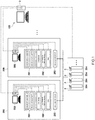
- the cylinder management system 100 of this embodiment is used for managing a gas cylinder 204 of one or multiple exhaust gas analysis systems 200 that analyze an engine exhaust gas discharged from a specimen as being a vehicle or a part of the vehicle.
- the specimen is a vehicle, an engine or a power train (a vehicle driving system).
- One or multiple exhaust gas analysis systems 200 are used for a test on the specimen, and comprise a load device 201 such as a chassis dynamometer on which a vehicle is loaded, an engine dynamometer connected to an output shaft of an engine or a driving system test facility to test a vehicle driving system, a test facility 202 such as a CVS device that samples an exhaust gas discharged from the specimen, an automatic driving robot or a fan, one or multiple gas analysis devices 203 that analyze a component to be measured in the exhaust gas, multiple gas cylinders 204 that supply a cylinder gas (a utility gas or a calibration gas in this embodiment) to one or the multiple gas analysis devices 203 and a control unit 205 that controls the load device 201, the test facility 202 or the gas analysis device 203 and that conducts the exhaust gas test based on a predetermined test schedule.
- a load device 201 such as a chassis dynamometer on which a vehicle is loaded
- an engine dynamometer connected to an output shaft of an engine or a driving system test
- the predetermined test schedule contains, for example, an exhaust gas certification test that corresponds to an enactment in each country, and may contain a cold start test, a transient test, a hot start test, a running gloss transpiration gas test, a hot soak transpiration gas test and a diurnal transpiration gas test.
- the test schedule is set by a user in advance.
- the utility gas is a gas that is necessary at a time of analyzing the exhaust gas by the gas analysis device 203, and for example, H 2 gas or O 2 gas.
- the calibration gas is a gas that is necessary at a time of calibrating the gas analysis device 203
- the calibration gas for span calibration is, for example, CO gas, CO 2 gas, C 3 H 8 gas, CH 4 gas, NO gas, NO 2 gas and N 2 O gas
- the calibration gas for zero calibration is, for example, N 2 gas.
- the calibration gas for span calibration is prepared for each concentration. A kind of the used gas or the concentration of the used gas is determined according to the test schedule by the gas analysis device (for low concentration, for high concentration).
- the gas analysis device is selected according to the gas for a passenger car, for a truck, for a gasoline-powered vehicle, for a diesel vehicle or for a natural gas vehicle.
- the multiple gas cylinders 204 may be collectedly arranged in a single cylinder chamber, or separately arranged in multiple cylinder chambers or in a predetermined portion.
- the multiple gas analysis devices 203 to which the gas is supplied from each gas cylinder 204 may be contained in a single exhaust gas analysis system 200 or may be contained in the multiple exhaust gas analysis systems 200.
- the cylinder management system 100 manages the multiple gas cylinders 204 by the use of the pressure of each of the multiple gas cylinders 204.
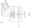
- the cylinder management system 100 comprises, as shown in Fig. 2 , multiple pressure sensors 2 that detect the pressure of each of the multiple gas cylinders 204 and a management device 3 that calculates a cylinder gas residual quantity in each gas cylinder 204 based on the pressure detected by each of the pressure sensors 2, and manages a timing to replace each gas cylinder 204.
- the pressure sensor 2 is arranged for each gas cylinder 204.
- the pressure sensor 2 may be fixed to the gas cylinder 204, or may be post installed to an output port of the gas cylinder 204.
- the pressure detection signal of the pressure sensor 2 is output to the management device 3 through a wired or wireless communication circuit.
- the management device 3 is a dedicated or general purpose device having a CPU, an internal memory, an input/output interface, an input device such as a key board or a mouse, an output device such as a display or a printer and a communication device that is communicable to the pressure sensor 2 or the control unit 205 through the communication circuit.
- the management device 3 produces functions as a cylinder gas residual quantity calculating part 31 and a replace timing managing part 32 by cooperatively working with the CPU and its peripheral devices based on cylinder management programs stored in the internal memory.
- the cylinder gas residual quantity calculating part 31 receives the pressure detection signal of the multiple pressure sensors 2 on a constant basis or intermittently, and calculates the cylinder gas residual quantity of each gas cylinder 204. Concretely, the cylinder gas residual quantity calculating part 31 calculates the cylinder gas residual quantity (unit: L) based on an electric current signal (unit: mA) output from each of the pressure sensors 2.
- the replace timing managing part 32 compares the cylinder gas residual quantity (R) of each gas cylinder 204 with the gas consumption quantity (U) assumed to be an accumulated quantity for each gas kind in the multiple gas analysis device 203, and estimates and manages the timing to replace each gas cylinder 204.
- the timing to replace the gas cylinder 204 may be a date, and may be a period from the present (for example, 30 days later).
- the replace timing managing part 32 obtains each test schedule of the multiple gas analysis devices 203 from the control unit 205 and calculates the gas consumption quantity (U) assumed to be used by all of the multiple gas analysis devices 203 for each gas type.
- the gas consumption quantity (U) assumed to be used for each gas type is a total value (U 1 + U 2 ) of a gas consumption quantity U 1 based on the test schedule and a gas consumption quantity U 2 used aside from the test schedule.
- the gas consumption quantity U 2 used aside from the test schedule is, for example, a gas consumption quantity during a maintenance conducted at a predetermined cycle (for example, once a month) set for each of the multiple gas analysis devices 203.
- the replace timing managing part 32 calculates the timing to replace the gas cylinder 204 by the use of the following expression. 0 ⁇ cylinder gas residual quantity R ⁇ number of days until replacement ⁇ a ⁇ number of days until replacement ⁇ b
- the coefficient "a” is an average gradient of the gas consumption quantity U 1 consumed in the test schedule.
- the coefficient “a” may be a value that differs in accordance with the gas analysis device 203 to be used.
- the coefficient "a” may be changed in accordance with a content of the test schedule.
- the coefficient "b” is an average gradient of the gas consumption quantity U 2 consumed during calibration that is conducted periodically.
- the coefficient "b” may be a value that differs in accordance with the gas analysis device 203 to be used.
- the replace timing managing part 32 also manages the timing to replace the gas cylinder 204 based on the delivery date of the gas cylinder 204.
- the replace timing managing part 32 calculates the timing to replace the gas cylinder 204 by the use of the following expression. 0 ⁇ cylinder gas residual quantity R ⁇ number of days until replacement + delivery date ⁇ a ⁇ number of days until replacement + delivery date ⁇ b
- the number of days until replacement (timing to replace) calculated by the above-mentioned expression is displayed on a display of the management device 3.
- a reporting means to issue an alarm to urge the user to replace the gas cylinder 204 may be provided.
- the management device 3 may have an ordering part that automatically places an order of the gas cylinder based on the calculated timing to replace the gas cylinder 204.
- the cylinder gas residual quantity (R) of the multiple gas cylinders 204 is calculated by the use of the multiple pressure sensors 2 each of which detects the pressure of each of the multiple gas cylinders 204, and the timing to replace each gas cylinder 204 is anticipated and managed, it becomes possible to collectively manage the timing to replace the multiple gas cylinders 204.
- the timing to replace each gas cylinder 204 is anticipated and managed, there is no need of going to the cylinder chamber and verifying the cylinder gas residual quantity (R) so that it is possible to shorten a period to interrupt the experiment and the test. In addition, it becomes possible to reduce human errors due to confirmation mistakes.
- This invention is not limited to the above-mentioned embodiment.
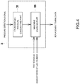
- the management device 3 may have a machine learning part 33 that anticipates the timing to replace the gas cylinder 204 by the use of machine learning algorithm.
- the machine learning part 33 anticipates the timing to replace each gas cylinder 204 based on the machine learning algorithm by the use of the gas type, a cylinder gas residual pressure of each gas cylinder 204, the test schedule of each gas analysis device 203 and the delivery date of each gas cylinder 204 as the input parameters.
- the machine learning part 33 may update the coefficient "a" and the coefficient "b" of the above-mentioned embodiment by the use of the machine learning algorithm.
- the replace timing managing part 32 may manage the timing to replace the gas cylinder 204 by comparing the cylinder gas residual quantity obtained by the cylinder gas residual quantity calculating part 31 with the gas consumption quantity in the test schedule of each gas analysis device 203 without using the calculation formula of the above-mentioned embodiment. In this case, the replace timing managing part 32 roughly estimates the gas consumption quantity in the test schedule of each gas analysis device 203, and manages the timing to replace the gas cylinder 204 by comparing the roughly estimated gas consumption quantity with the cylinder gas residual quantity.
- the management device 3 in the above-mentioned embodiment may have a function of detecting a gas leak between the multiple gas analysis devices 203 and the multiple gas cylinders 204.
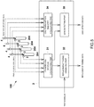
- the exhaust gas analysis system 200 is provided with multiple flow rate sensors 4 that detect a flow rate of a fluid that flows in each of the multiple gas analysis devices 203.
- the management device 3 has a gas consumption quantity calculating part 34 that calculates the gas consumption quantity of each gas analysis device 203 from the detected flow rate of each flow rate sensor 4, and a leak detecting part 35 that detects the gas leak from the cylinder gas residual quantity and the gas consumption quantity.
- the leak detecting part 35 compares the gas consumption quantity obtained from the cylinder gas residual quantity with the gas consumption quantity obtained from the detected flow rate of the flow rate sensor 4. In case that the difference is out of a predetermined range, the leak detecting part 35 judges that the gas leak occurs. It is preferable to provide a reporting means to issues an alarm that reports the occurrence of the gas leak.
- the management device 3 may have only the function of detecting the gas leak without managing the timing to replace the gas cylinder.
Landscapes
- Physics & Mathematics (AREA)
- General Physics & Mathematics (AREA)
- Engineering & Computer Science (AREA)
- Chemical & Material Sciences (AREA)
- Business, Economics & Management (AREA)
- Combustion & Propulsion (AREA)
- Economics (AREA)
- Life Sciences & Earth Sciences (AREA)
- Health & Medical Sciences (AREA)
- Theoretical Computer Science (AREA)
- Accounting & Taxation (AREA)
- Strategic Management (AREA)
- Tourism & Hospitality (AREA)
- Operations Research (AREA)
- General Business, Economics & Management (AREA)
- Marketing (AREA)
- Human Resources & Organizations (AREA)
- Entrepreneurship & Innovation (AREA)
- Development Economics (AREA)
- Quality & Reliability (AREA)
- Finance (AREA)
- Food Science & Technology (AREA)
- Fluid Mechanics (AREA)
- Medicinal Chemistry (AREA)
- Analytical Chemistry (AREA)
- Biochemistry (AREA)
- General Health & Medical Sciences (AREA)
- Immunology (AREA)
- Pathology (AREA)
- Examining Or Testing Airtightness (AREA)
- Sampling And Sample Adjustment (AREA)
- Filling Or Discharging Of Gas Storage Vessels (AREA)
- Testing Of Engines (AREA)
- Measurement Of Levels Of Liquids Or Fluent Solid Materials (AREA)
Abstract
Description
- This invention relates to a cylinder management system, a cylinder management program and a gas leak detection system.
- In the background of fuel-efficient competition or coping with a regulation, complicated business or increase of workload such as motorization or connectivity, it is required experiments and tests be conducted efficiently in developing an automobile. In case of dealing with analyzers for experiments or test, it is necessary to verify the cylinder gas residual quantity of a gas cylinder into which a calibration gas is enclosed in advance or to update the concentration value of the calibration gas at a time of replacing the gas cylinder not to interrupt the experiments or the tests. In case of updating the concentration value of the calibration gas, most users take a note of the concentration value of the gas cylinder at hand and manually input and set the concentration value of the calibration gas in front of the analyzer.
- A cylinder management system that makes it easy to set the concentration of the calibration gas is disclosed in the patent document 1. The test system shown in the patent document 1 is so configured that the kind of the span gas and the concentration of the span gas can be collected set for multiple analysis devices.
- However, in order to verify the residual quantity of the cylinder gas in the multiple gas cylinders, it is necessary to go to the cylinder chamber where the gas cylinders are housed, and it takes time to go to the cylinder chamber placed various places and to verify the residual quantity of each cylinder gas. As a result of this, the period while the experiment and the test are interrupted becomes long. In addition, human errors might easily be caused due to verification error.
- Patent document 1: Japanese Patent No.
5718277 - This invention is to solve all of the problems and a main object of this invention is to collectively manage a timing to replace multiple cylinders.
- More specifically, a cylinder management system in accordance with this invention is a cylinder management system that manages multiple gas cylinders that supply a cylinder gas to a gas analysis device that analyzes an exhaust gas of a specimen as being a vehicle or a part of the vehicle, and is characterized by comprising multiple pressure sensors each of which detects a pressure of each of the multiple gas cylinders, and a management device that calculates a cylinder gas residual quantity in each of the gas cylinders based on the pressure detected by each of the pressure sensors, compares the cylinder gas residual quantity in each of the gas cylinders with a gas consumption quantity assumed to be used for each gas type by the gas analysis device and manages a timing to replace each of the gas cylinders.
- In accordance with this arrangement, since the timing to replace each of the gas cylinders is managed by calculating the cylinder gas residual quantity of the multiple gas cylinders by the use of the multiple pressure sensors that detect the pressure of each of the multiple gas cylinders, it becomes possible to collectively manage the timing to replace the multiple gas cylinders. In addition, since the timing to replace each of the gas cylinders is managed, there is no need of going to a cylinder chamber and verifying the cylinder gas residual quantity so that it is possible to shorten a period to interrupt an experiment and a test. In addition, it becomes possible to reduce human errors due to confirmation mistakes.
- A test system such as an exhaust gas analysis system comprises multiple gas analysis devices. In order to preferably use this test system, it is preferable that the management device accumulates the gas consumption quantity assumed to be used for each gas type by the multiple gas analysis devices, and compares the accumulated gas consumption quantity with the cylinder gas residual quantity in each of the gas cylinders.
- It is preferable that the management device manages the timing to replace the cylinder by comparing the cylinder gas residual quantity of each gas cylinder with the gas consumption quantity assumed to be used for each gas type by the multiple gas analysis devices.
- In accordance with this arrangement, since the timing to replace the gas cylinder can be managed in consideration with the assumed gas consumption quantity, it is possible to replace the gas cylinder before the residual quantity of the cylinder gas reaches zero. As a result of this, it is possible to shorten the stand-by time while the test is interrupted.
- It is preferable that the management device obtains a test schedule for each of the multiple gas analysis devices and calculates the gas consumption quantity assumed to be used by the multiple gas analysis devices for each gas type based on these test schedules.
- In accordance with this arrangement, since the gas consumption quantity (assumed) to be used by each of the gas analysis devices can be previously anticipated, it is possible to replace the gas cylinder before the cylinder gas residual quantity reaches zero. As this result, it becomes possible not to interrupt the test.
- Some gas type in the gas cylinder is used apart from the test schedule. In order to manage the timing to replace the gas cylinder more accurately, it is preferable that the management device uses a total value of the gas consumption quantity based on the test schedule and the gas consumption quantity used aside from the test schedule as the gas consumption quantity assumed to be used by the multiple gas analysis devices for each gas type.
- It is preferable that the management device uses the gas consumption quantity in maintenance of a predetermined cycle set for each of the multiple gas analysis devices as the gas consumption quantity used aside from the test schedule.
- It is preferable that the management device manages the timing to replace the gas cylinder based on a delivery date of the gas cylinder.
- In accordance with this arrangement, it is possible to replace the gas cylinder without making the cylinder gas residual quantity of the gas cylinder zero.
- In order to manage the timing to replace the gas cylinder more accurately, it is preferable that the management device has a machine learning part that anticipates the timing to replace the gas cylinder based on a machine learning algorithm by the use of a gas type, a gas residual pressure of the gas cylinder and the test schedule as input parameters.
- In addition, a cylinder management method in accordance with this invention is a cylinder management method that manages multiple gas cylinders that supply a cylinder gas to a gas analysis device that analyzes an exhaust gas of a specimen as being a vehicle or a part of the vehicle, and that comprises steps of detecting a pressure of each of the multiple gas cylinders by providing a pressure sensor to each of the multiple gas cylinders, and calculating a cylinder gas residual quantity in each of the gas cylinders based on the pressure detected by each of the pressure sensors, and comparing the cylinder gas residual quantity in each of the gas cylinders with a gas consumption quantity assumed to be used for each gas type by the gas analysis device so that a timing to replace each of the gas cylinders is managed.
- Furthermore, a cylinder management program in accordance with this invention is a cylinder management program that is used for a system having multiple gas cylinders that supply a cylinder gas to a gas analysis device that analyzes an exhaust gas of a specimen as being a vehicle or a part of the vehicle and multiple pressure sensors each of which detects a pressure of each of the multiple gas cylinders, and is characterized by providing a computer with functions as a cylinder gas residual quantity calculating part that calculates a cylinder gas residual quantity in each of the gas cylinders based on the detected pressure of each of the pressure sensors, and a replace timing managing part that compares the cylinder gas residual quantity in each of the gas cylinders with a gas consumption quantity assumed to be used for each gas type by the gas analysis device and manages a timing to replace each of the gas cylinders.
- In addition, a gas leak detection system in accordance with this invention is a gas leak detection system that detects a gas leak between a gas analysis device that analyzes an exhaust gas of a specimen as being a vehicle or a part of the vehicle and multiple gas cylinders that supply a cylinder gas to the gas analysis device, and is characterized by comprising multiple pressure sensors each of which detects a pressure of each of the multiple gas cylinders, a flow rate sensor that detects a flow rate of a fluid flowing in the gas analysis device, and a management device that calculates a cylinder gas residual quantity in each of the gas cylinders based on the pressure detected by each of the pressure sensors, calculates a gas consumption quantity of the gas analysis device based on the detected flow rate of the flow rate sensor, and detects the gas leak based on the cylinder gas residual quantity and the gas consumption quantity.
- In accordance with this arrangement, since the cylinder gas residual quantity of each gas cylinder is calculated based on the pressure detected by each pressure sensor, the gas consumption quantity of the gas analysis device is calculated from the flow rate detected by the flow rate sensor and the gas leak is detected based on the cylinder gas residual quantity and the gas consumption quantity, it is possible to collectively monitor the gas leak in the system wherein the multiple gas cylinders are connected to the gas analysis device.
- In accordance with this invention having this arrangement, it is possible to collectively manage the timing to replace the multiple cylinders.
-
-
Fig. 1 is a schematic diagram showing a configuration of an exhaust gas analysis system of this embodiment. -
Fig. 2 is a schematic diagram showing a configuration of a cylinder management system of this embodiment. -
Fig. 3 is a schematic diagram showing a chronological change of a cylinder gas residual quantity in a gas cylinder -
Fig. 4 is a schematic diagram showing a configuration of a cylinder management system of a modified embodiment. -
Fig. 5 is a schematic diagram showing a configuration of a cylinder management system of a modified embodiment. - One embodiment of a cylinder management system in accordance with this invention will be explained with reference to drawings.
- The
cylinder management system 100 of this embodiment, as shown inFig. 1 , is used for managing agas cylinder 204 of one or multiple exhaustgas analysis systems 200 that analyze an engine exhaust gas discharged from a specimen as being a vehicle or a part of the vehicle. The specimen is a vehicle, an engine or a power train (a vehicle driving system). - One or multiple exhaust
gas analysis systems 200 are used for a test on the specimen, and comprise aload device 201 such as a chassis dynamometer on which a vehicle is loaded, an engine dynamometer connected to an output shaft of an engine or a driving system test facility to test a vehicle driving system, atest facility 202 such as a CVS device that samples an exhaust gas discharged from the specimen, an automatic driving robot or a fan, one or multiplegas analysis devices 203 that analyze a component to be measured in the exhaust gas,multiple gas cylinders 204 that supply a cylinder gas (a utility gas or a calibration gas in this embodiment) to one or the multiplegas analysis devices 203 and acontrol unit 205 that controls theload device 201, thetest facility 202 or thegas analysis device 203 and that conducts the exhaust gas test based on a predetermined test schedule. One or the multiple exhaustgas analysis systems 200 may be arranged in a building or separately arranged in multiple buildings. The predetermined test schedule contains, for example, an exhaust gas certification test that corresponds to an enactment in each country, and may contain a cold start test, a transient test, a hot start test, a running gloss transpiration gas test, a hot soak transpiration gas test and a diurnal transpiration gas test. The test schedule is set by a user in advance. - The utility gas is a gas that is necessary at a time of analyzing the exhaust gas by the
gas analysis device 203, and for example, H2 gas or O2 gas. In addition, the calibration gas is a gas that is necessary at a time of calibrating thegas analysis device 203, the calibration gas for span calibration is, for example, CO gas, CO2 gas, C3H8 gas, CH4 gas, NO gas, NO2 gas and N2O gas, and the calibration gas for zero calibration is, for example, N2 gas. The calibration gas for span calibration is prepared for each concentration. A kind of the used gas or the concentration of the used gas is determined according to the test schedule by the gas analysis device (for low concentration, for high concentration). The gas analysis device is selected according to the gas for a passenger car, for a truck, for a gasoline-powered vehicle, for a diesel vehicle or for a natural gas vehicle. - The
multiple gas cylinders 204 may be collectedly arranged in a single cylinder chamber, or separately arranged in multiple cylinder chambers or in a predetermined portion. The multiplegas analysis devices 203 to which the gas is supplied from eachgas cylinder 204 may be contained in a single exhaustgas analysis system 200 or may be contained in the multiple exhaustgas analysis systems 200. - The
cylinder management system 100 manages themultiple gas cylinders 204 by the use of the pressure of each of themultiple gas cylinders 204. - Concretely, the
cylinder management system 100 comprises, as shown inFig. 2 ,multiple pressure sensors 2 that detect the pressure of each of themultiple gas cylinders 204 and amanagement device 3 that calculates a cylinder gas residual quantity in eachgas cylinder 204 based on the pressure detected by each of thepressure sensors 2, and manages a timing to replace eachgas cylinder 204. - The
pressure sensor 2 is arranged for eachgas cylinder 204. Thepressure sensor 2 may be fixed to thegas cylinder 204, or may be post installed to an output port of thegas cylinder 204. The pressure detection signal of thepressure sensor 2 is output to themanagement device 3 through a wired or wireless communication circuit. - The
management device 3 is a dedicated or general purpose device having a CPU, an internal memory, an input/output interface, an input device such as a key board or a mouse, an output device such as a display or a printer and a communication device that is communicable to thepressure sensor 2 or thecontrol unit 205 through the communication circuit. - The
management device 3 produces functions as a cylinder gas residualquantity calculating part 31 and a replacetiming managing part 32 by cooperatively working with the CPU and its peripheral devices based on cylinder management programs stored in the internal memory. - The cylinder gas residual
quantity calculating part 31 receives the pressure detection signal of themultiple pressure sensors 2 on a constant basis or intermittently, and calculates the cylinder gas residual quantity of eachgas cylinder 204. Concretely, the cylinder gas residualquantity calculating part 31 calculates the cylinder gas residual quantity (unit: L) based on an electric current signal (unit: mA) output from each of thepressure sensors 2. - The replace
timing managing part 32 compares the cylinder gas residual quantity (R) of eachgas cylinder 204 with the gas consumption quantity (U) assumed to be an accumulated quantity for each gas kind in the multiplegas analysis device 203, and estimates and manages the timing to replace eachgas cylinder 204. The timing to replace thegas cylinder 204 may be a date, and may be a period from the present (for example, 30 days later). - In addition, the replace
timing managing part 32 obtains each test schedule of the multiplegas analysis devices 203 from thecontrol unit 205 and calculates the gas consumption quantity (U) assumed to be used by all of the multiplegas analysis devices 203 for each gas type. - The gas consumption quantity (U) assumed to be used for each gas type is a total value (U1 + U2) of a gas consumption quantity U1 based on the test schedule and a gas consumption quantity U2 used aside from the test schedule. The gas consumption quantity U2 used aside from the test schedule is, for example, a gas consumption quantity during a maintenance conducted at a predetermined cycle (for example, once a month) set for each of the multiple
gas analysis devices 203. - Concretely, as shown in
Fig. 3 , the replacetiming managing part 32 calculates the timing to replace thegas cylinder 204 by the use of the following expression.
- The coefficient "a" is an average gradient of the gas consumption quantity U1 consumed in the test schedule. The coefficient "a" may be a value that differs in accordance with the
gas analysis device 203 to be used. In addition, the coefficient "a" may be changed in accordance with a content of the test schedule. - In addition, the coefficient "b" is an average gradient of the gas consumption quantity U2 consumed during calibration that is conducted periodically. The coefficient "b" may be a value that differs in accordance with the
gas analysis device 203 to be used. - Furthermore, the replace
timing managing part 32 also manages the timing to replace thegas cylinder 204 based on the delivery date of thegas cylinder 204. In this case, the replacetiming managing part 32 calculates the timing to replace thegas cylinder 204 by the use of the following expression.
- The number of days until replacement (timing to replace) calculated by the above-mentioned expression is displayed on a display of the
management device 3. In addition, in case that the timing to replace thegas cylinder 204 is shorter than a predetermined cycle, a reporting means to issue an alarm to urge the user to replace thegas cylinder 204 may be provided. Furthermore, themanagement device 3 may have an ordering part that automatically places an order of the gas cylinder based on the calculated timing to replace thegas cylinder 204. - In accordance with the
cylinder management system 100 of this embodiment, since the cylinder gas residual quantity (R) of themultiple gas cylinders 204 is calculated by the use of themultiple pressure sensors 2 each of which detects the pressure of each of themultiple gas cylinders 204, and the timing to replace eachgas cylinder 204 is anticipated and managed, it becomes possible to collectively manage the timing to replace themultiple gas cylinders 204. In addition, since the timing to replace eachgas cylinder 204 is anticipated and managed, there is no need of going to the cylinder chamber and verifying the cylinder gas residual quantity (R) so that it is possible to shorten a period to interrupt the experiment and the test. In addition, it becomes possible to reduce human errors due to confirmation mistakes. - This invention is not limited to the above-mentioned embodiment.
- For example, as shown in
Fig. 4 , themanagement device 3 may have amachine learning part 33 that anticipates the timing to replace thegas cylinder 204 by the use of machine learning algorithm. Concretely, themachine learning part 33 anticipates the timing to replace eachgas cylinder 204 based on the machine learning algorithm by the use of the gas type, a cylinder gas residual pressure of eachgas cylinder 204, the test schedule of eachgas analysis device 203 and the delivery date of eachgas cylinder 204 as the input parameters. In addition, themachine learning part 33 may update the coefficient "a" and the coefficient "b" of the above-mentioned embodiment by the use of the machine learning algorithm. - The replace
timing managing part 32 may manage the timing to replace thegas cylinder 204 by comparing the cylinder gas residual quantity obtained by the cylinder gas residualquantity calculating part 31 with the gas consumption quantity in the test schedule of eachgas analysis device 203 without using the calculation formula of the above-mentioned embodiment. In this case, the replacetiming managing part 32 roughly estimates the gas consumption quantity in the test schedule of eachgas analysis device 203, and manages the timing to replace thegas cylinder 204 by comparing the roughly estimated gas consumption quantity with the cylinder gas residual quantity. - In addition, the
management device 3 in the above-mentioned embodiment may have a function of detecting a gas leak between the multiplegas analysis devices 203 and themultiple gas cylinders 204. In this case, as shown inFig. 5 , the exhaustgas analysis system 200 is provided with multipleflow rate sensors 4 that detect a flow rate of a fluid that flows in each of the multiplegas analysis devices 203. - As shown in
Fig. 5 , in addition to the cylinder gas residualquantity calculating part 31, themanagement device 3 has a gas consumptionquantity calculating part 34 that calculates the gas consumption quantity of eachgas analysis device 203 from the detected flow rate of eachflow rate sensor 4, and aleak detecting part 35 that detects the gas leak from the cylinder gas residual quantity and the gas consumption quantity. Theleak detecting part 35 compares the gas consumption quantity obtained from the cylinder gas residual quantity with the gas consumption quantity obtained from the detected flow rate of theflow rate sensor 4. In case that the difference is out of a predetermined range, theleak detecting part 35 judges that the gas leak occurs. It is preferable to provide a reporting means to issues an alarm that reports the occurrence of the gas leak. - The
management device 3 may have only the function of detecting the gas leak without managing the timing to replace the gas cylinder. - Various modifications or combinations of the embodiments may be made without departing from the spirit of this invention.
-
- 100
- cylinder management system
- 203
- gas analysis system
- 204
- gas cylinder
- 2
- pressure sensor
- R
- cylinder gas residual quantity
- U
- gas consumption quantity
- U1
- gas consumption quantity based on test schedule
- U2
- gas consumption quantity used during maintenance
- 3
- management device
- 31
- cylinder gas residual quantity calculating part
- 32
- replace timing managing part
- 33
- machine learning part
- 34
- gas consumption quantity calculating part
- 35
- leak detecting part
Claims (10)
- A cylinder management system that manages multiple gas cylinders that supply a cylinder gas to a gas analysis device that analyzes an exhaust gas of a specimen as being a vehicle or a part of the vehicle, comprising
multiple pressure sensors each of which detects a pressure of each of the multiple gas cylinders, and
a management device that calculates a cylinder gas residual quantity in each of the gas cylinders based on the pressure detected by each of the pressure sensors, compares the cylinder gas residual quantity in each of the gas cylinders with a gas consumption quantity assumed to be used for each gas type by the gas analysis device and manages a timing to replace each of the gas cylinders. - The cylinder management system described in claim 1, wherein
the multiple gas analysis devices are arranged, and
the management device accumulates the gas consumption quantity assumed to be used for each gas type by the multiple gas analysis devices, and compares the accumulated gas consumption quantity with the cylinder gas residual quantity in each of the gas cylinders. - The cylinder management system described in claim 2, wherein
the management device obtains a test schedule for each of the multiple gas analysis devices and calculates the gas consumption quantity assumed to be used by the multiple gas analysis devices for each gas type based on these test schedules. - The cylinder management system described in claim 3, wherein
the management device uses a total value of the gas consumption quantity based on the test schedule and the gas consumption quantity used aside from the test schedule as the gas consumption quantity assumed to be used by the multiple gas analysis devices for each gas type. - The cylinder management system described in claim 4, wherein
the management device uses the gas consumption quantity in maintenance of a predetermined cycle set for each of the multiple gas analysis devices as the gas consumption quantity used aside from the test schedule. - The cylinder management system described in claim 1, wherein
the management device manages the timing to replace the gas cylinder based on a delivery date of the gas cylinder. - The cylinder management system described in claim 1, wherein
the management device has a machine learning part that anticipates the timing to replace the gas cylinder based on a machine learning algorithm by the use of a gas type, a gas residual pressure of the gas cylinder and the test schedule as input parameters. - A cylinder management method that manages multiple gas cylinders that supply a cylinder gas to a gas analysis device that analyzes an exhaust gas of a specimen as being a vehicle or a part of the vehicle, comprising steps of
detecting a pressure of each of the multiple gas cylinders by providing a pressure sensor to each of the multiple gas cylinders, and
calculating a cylinder gas residual quantity in each of the gas cylinders based on the pressure detected by each of the pressure sensors, and comparing the cylinder gas residual quantity in each of the gas cylinders with a gas consumption quantity assumed to be used for each gas type by the gas analysis device so that a timing to replace each of the gas cylinders is managed. - A cylinder management program that is used for a system having multiple gas cylinders that supply a cylinder gas to a gas analysis device that analyzes an exhaust gas of a specimen as being a vehicle or a part of the vehicle and multiple pressure sensors each of which detects a pressure of each of the multiple gas cylinders, providing a computer with functions as
a cylinder gas residual quantity calculating part that calculates a cylinder gas residual quantity in each of the gas cylinders based on the detected pressure of each of the pressure sensors, and
a replace timing managing part that compares the cylinder gas residual quantity in each of the gas cylinders with a gas consumption quantity assumed to be used for each gas type by the gas analysis device and manages a timing to replace each of the gas cylinders. - A gas leak detection system that detects a gas leak between a gas analysis device that analyzes an exhaust gas of a specimen as being a vehicle or a part of the vehicle and multiple gas cylinders that supply a cylinder gas to the gas analysis device, wherein comprising
multiple pressure sensors each of which detects a pressure of each of the multiple gas cylinders,
a flow rate sensor that detects a flow rate of a fluid flowing in the gas analysis device, and
a management device that calculates a cylinder gas residual quantity in each of the gas cylinders based on the pressure detected by each of the pressure sensors, calculates a gas consumption quantity of the gas analysis device based on the detected flow rate of the flow rate sensor, and detects the gas leak based on the cylinder gas residual quantity and the gas consumption quantity.
Applications Claiming Priority (1)
| Application Number | Priority Date | Filing Date | Title |
|---|---|---|---|
| JP2018093475A JP6998269B2 (en) | 2018-05-15 | 2018-05-15 | Cylinder management system, cylinder management program and gas leak detection system |
Publications (3)
| Publication Number | Publication Date |
|---|---|
| EP3570025A2 true EP3570025A2 (en) | 2019-11-20 |
| EP3570025A3 EP3570025A3 (en) | 2020-02-12 |
| EP3570025B1 EP3570025B1 (en) | 2024-09-18 |
Family
ID=66529908
Family Applications (1)
| Application Number | Title | Priority Date | Filing Date |
|---|---|---|---|
| EP19174166.9A Active EP3570025B1 (en) | 2018-05-15 | 2019-05-13 | Cylinder management system, cylinder management method and cylinder management program |
Country Status (4)
| Country | Link |
|---|---|
| US (1) | US11243137B2 (en) |
| EP (1) | EP3570025B1 (en) |
| JP (1) | JP6998269B2 (en) |
| CN (1) | CN110487492A (en) |
Families Citing this family (2)
| Publication number | Priority date | Publication date | Assignee | Title |
|---|---|---|---|---|
| JPWO2023095832A1 (en) * | 2021-11-25 | 2023-06-01 | ||
| WO2023112597A1 (en) * | 2021-12-15 | 2023-06-22 | 株式会社堀場製作所 | Gas analysis device, exhaust gas analysis system, and gas analysis method |
Family Cites Families (10)
| Publication number | Priority date | Publication date | Assignee | Title |
|---|---|---|---|---|
| JPH079065Y2 (en) * | 1989-03-15 | 1995-03-06 | 矢崎総業株式会社 | Gas leak monitoring device |
| JPH06300656A (en) * | 1993-04-16 | 1994-10-28 | Nippon Steel Corp | Gas leak detector |
| JP3796015B2 (en) * | 1997-08-07 | 2006-07-12 | 株式会社堀場製作所 | Centralized control system for gas cylinders for inspection and adjustment of gas analyzers |
| JP3667607B2 (en) | 2000-08-25 | 2005-07-06 | 株式会社堀場製作所 | Automotive exhaust gas measurement system |
| CN2676170Y (en) * | 2003-05-09 | 2005-02-02 | 浙江三花股份有限公司 | Integrated test system for one-way valve |
| US7231811B2 (en) * | 2004-05-07 | 2007-06-19 | Nehemia Sagi | Adaptive leak testing method |
| JP5718277B2 (en) * | 2012-05-24 | 2015-05-13 | 株式会社堀場製作所 | Test system |
| JP6529768B2 (en) | 2015-01-22 | 2019-06-12 | Sppテクノロジーズ株式会社 | Management system for semiconductor manufacturing equipment |
| US11327475B2 (en) * | 2016-05-09 | 2022-05-10 | Strong Force Iot Portfolio 2016, Llc | Methods and systems for intelligent collection and analysis of vehicle data |
| CN106052790A (en) * | 2016-06-23 | 2016-10-26 | 珠海格力电器股份有限公司 | Gas monitoring device and method and gas storage device |
-
2018
- 2018-05-15 JP JP2018093475A patent/JP6998269B2/en active Active
-
2019
- 2019-05-13 EP EP19174166.9A patent/EP3570025B1/en active Active
- 2019-05-15 US US16/412,816 patent/US11243137B2/en active Active
- 2019-05-15 CN CN201910404771.XA patent/CN110487492A/en active Pending
Non-Patent Citations (1)
| Title |
|---|
| None |
Also Published As
| Publication number | Publication date |
|---|---|
| EP3570025B1 (en) | 2024-09-18 |
| CN110487492A (en) | 2019-11-22 |
| EP3570025A3 (en) | 2020-02-12 |
| JP2019200076A (en) | 2019-11-21 |
| US11243137B2 (en) | 2022-02-08 |
| JP6998269B2 (en) | 2022-01-18 |
| US20190353551A1 (en) | 2019-11-21 |
Similar Documents
| Publication | Publication Date | Title |
|---|---|---|
| Xia et al. | Mathematical description for the measurement and verification of energy efficiency improvement | |
| US10620174B2 (en) | Method for improving accuracy of sensor outputs for measuring NOx, and system and apparatus for same | |
| EP2592409B1 (en) | Test system | |
| US11320335B2 (en) | Systems and methods for testing gas leak detectors | |
| US20090282808A1 (en) | Method and system for improving sensor accuracy | |
| US9322741B2 (en) | Exhaust gas analyzing system | |
| EP3570025B1 (en) | Cylinder management system, cylinder management method and cylinder management program | |
| JP2017211235A (en) | Exhaust gas analysis system, program for exhaust gas analysis, and exhaust gas analysis method | |
| EP2667172B1 (en) | Test system | |
| CN118817616B (en) | A sewage online monitoring system based on data analysis | |
| US9194274B2 (en) | Particulate measurement system | |
| CN120782463A (en) | Uncertainty evaluation method based on carbon emission monitoring method and nuclear algorithm | |
| US11475380B2 (en) | Vehicle test facility operation rate analysis system and method | |
| JP5815841B2 (en) | Fuel flow measurement device and calibration device thereof | |
| CN114740159A (en) | Natural gas energy metering component acquisition method and Internet of things system | |
| JP5931588B2 (en) | Test system | |
| CN110090497A (en) | Air filter replacing options, replacing construction detection method and device and fuel cell system | |
| CN115809749B (en) | Method for establishing comprehensive online prediction model of sewage treatment and prediction and early warning method | |
| CN115792135B (en) | Method, system and medium for testing air quality in vehicle | |
| RU2190875C2 (en) | Method and system for determining the amount of released pollutants into the environment | |
| CN113591221B (en) | Method and system for detecting energy consumption change of vehicle | |
| EP3683563B1 (en) | Dilution tunnel internal aqueous condensation monitoring system and method for vehicle emission tests | |
| CN118982257A (en) | A power supply method and system based on transfer learning | |
| Appel et al. | Investigations on Total Error in Emission Measurements Under Real Driving Conditions | |
| Miñarro et al. | Do pressure changes have an influence on ambient air chemiluminescence NOx measurements? |
Legal Events
| Date | Code | Title | Description |
|---|---|---|---|
| PUAI | Public reference made under article 153(3) epc to a published international application that has entered the european phase |
Free format text: ORIGINAL CODE: 0009012 |
|
| STAA | Information on the status of an ep patent application or granted ep patent |
Free format text: STATUS: THE APPLICATION HAS BEEN PUBLISHED |
|
| AK | Designated contracting states |
Kind code of ref document: A2 Designated state(s): AL AT BE BG CH CY CZ DE DK EE ES FI FR GB GR HR HU IE IS IT LI LT LU LV MC MK MT NL NO PL PT RO RS SE SI SK SM TR |
|
| AX | Request for extension of the european patent |
Extension state: BA ME |
|
| PUAL | Search report despatched |
Free format text: ORIGINAL CODE: 0009013 |
|
| AK | Designated contracting states |
Kind code of ref document: A3 Designated state(s): AL AT BE BG CH CY CZ DE DK EE ES FI FR GB GR HR HU IE IS IT LI LT LU LV MC MK MT NL NO PL PT RO RS SE SI SK SM TR |
|
| AX | Request for extension of the european patent |
Extension state: BA ME |
|
| RIC1 | Information provided on ipc code assigned before grant |
Ipc: G01M 15/02 20060101ALI20200109BHEP Ipc: G01M 15/10 20060101ALI20200109BHEP Ipc: G01N 33/00 20060101AFI20200109BHEP |
|
| STAA | Information on the status of an ep patent application or granted ep patent |
Free format text: STATUS: REQUEST FOR EXAMINATION WAS MADE |
|
| 17P | Request for examination filed |
Effective date: 20200728 |
|
| RBV | Designated contracting states (corrected) |
Designated state(s): AL AT BE BG CH CY CZ DE DK EE ES FI FR GB GR HR HU IE IS IT LI LT LU LV MC MK MT NL NO PL PT RO RS SE SI SK SM TR |
|
| STAA | Information on the status of an ep patent application or granted ep patent |
Free format text: STATUS: EXAMINATION IS IN PROGRESS |
|
| 17Q | First examination report despatched |
Effective date: 20220401 |
|
| P01 | Opt-out of the competence of the unified patent court (upc) registered |
Effective date: 20231108 |
|
| GRAP | Despatch of communication of intention to grant a patent |
Free format text: ORIGINAL CODE: EPIDOSNIGR1 |
|
| STAA | Information on the status of an ep patent application or granted ep patent |
Free format text: STATUS: GRANT OF PATENT IS INTENDED |
|
| INTG | Intention to grant announced |
Effective date: 20240426 |
|
| GRAS | Grant fee paid |
Free format text: ORIGINAL CODE: EPIDOSNIGR3 |
|
| GRAA | (expected) grant |
Free format text: ORIGINAL CODE: 0009210 |
|
| STAA | Information on the status of an ep patent application or granted ep patent |
Free format text: STATUS: THE PATENT HAS BEEN GRANTED |
|
| AK | Designated contracting states |
Kind code of ref document: B1 Designated state(s): AL AT BE BG CH CY CZ DE DK EE ES FI FR GB GR HR HU IE IS IT LI LT LU LV MC MK MT NL NO PL PT RO RS SE SI SK SM TR |
|
| REG | Reference to a national code |
Ref country code: GB Ref legal event code: FG4D |
|
| REG | Reference to a national code |
Ref country code: CH Ref legal event code: EP |
|
| REG | Reference to a national code |
Ref country code: IE Ref legal event code: FG4D |
|
| REG | Reference to a national code |
Ref country code: DE Ref legal event code: R096 Ref document number: 602019058997 Country of ref document: DE |
|
| REG | Reference to a national code |
Ref country code: LT Ref legal event code: MG9D |
|
| PG25 | Lapsed in a contracting state [announced via postgrant information from national office to epo] |
Ref country code: NO Free format text: LAPSE BECAUSE OF FAILURE TO SUBMIT A TRANSLATION OF THE DESCRIPTION OR TO PAY THE FEE WITHIN THE PRESCRIBED TIME-LIMIT Effective date: 20241218 |
|
| PG25 | Lapsed in a contracting state [announced via postgrant information from national office to epo] |
Ref country code: GR Free format text: LAPSE BECAUSE OF FAILURE TO SUBMIT A TRANSLATION OF THE DESCRIPTION OR TO PAY THE FEE WITHIN THE PRESCRIBED TIME-LIMIT Effective date: 20241219 Ref country code: FI Free format text: LAPSE BECAUSE OF FAILURE TO SUBMIT A TRANSLATION OF THE DESCRIPTION OR TO PAY THE FEE WITHIN THE PRESCRIBED TIME-LIMIT Effective date: 20240918 |
|
| PG25 | Lapsed in a contracting state [announced via postgrant information from national office to epo] |
Ref country code: BG Free format text: LAPSE BECAUSE OF FAILURE TO SUBMIT A TRANSLATION OF THE DESCRIPTION OR TO PAY THE FEE WITHIN THE PRESCRIBED TIME-LIMIT Effective date: 20240918 |
|
| PG25 | Lapsed in a contracting state [announced via postgrant information from national office to epo] |
Ref country code: LV Free format text: LAPSE BECAUSE OF FAILURE TO SUBMIT A TRANSLATION OF THE DESCRIPTION OR TO PAY THE FEE WITHIN THE PRESCRIBED TIME-LIMIT Effective date: 20240918 |
|
| PG25 | Lapsed in a contracting state [announced via postgrant information from national office to epo] |
Ref country code: HR Free format text: LAPSE BECAUSE OF FAILURE TO SUBMIT A TRANSLATION OF THE DESCRIPTION OR TO PAY THE FEE WITHIN THE PRESCRIBED TIME-LIMIT Effective date: 20240918 |
|
| REG | Reference to a national code |
Ref country code: NL Ref legal event code: MP Effective date: 20240918 |
|
| PG25 | Lapsed in a contracting state [announced via postgrant information from national office to epo] |
Ref country code: RS Free format text: LAPSE BECAUSE OF FAILURE TO SUBMIT A TRANSLATION OF THE DESCRIPTION OR TO PAY THE FEE WITHIN THE PRESCRIBED TIME-LIMIT Effective date: 20241218 |
|
| PG25 | Lapsed in a contracting state [announced via postgrant information from national office to epo] |
Ref country code: RS Free format text: LAPSE BECAUSE OF FAILURE TO SUBMIT A TRANSLATION OF THE DESCRIPTION OR TO PAY THE FEE WITHIN THE PRESCRIBED TIME-LIMIT Effective date: 20241218 Ref country code: NO Free format text: LAPSE BECAUSE OF FAILURE TO SUBMIT A TRANSLATION OF THE DESCRIPTION OR TO PAY THE FEE WITHIN THE PRESCRIBED TIME-LIMIT Effective date: 20241218 Ref country code: LV Free format text: LAPSE BECAUSE OF FAILURE TO SUBMIT A TRANSLATION OF THE DESCRIPTION OR TO PAY THE FEE WITHIN THE PRESCRIBED TIME-LIMIT Effective date: 20240918 Ref country code: HR Free format text: LAPSE BECAUSE OF FAILURE TO SUBMIT A TRANSLATION OF THE DESCRIPTION OR TO PAY THE FEE WITHIN THE PRESCRIBED TIME-LIMIT Effective date: 20240918 Ref country code: GR Free format text: LAPSE BECAUSE OF FAILURE TO SUBMIT A TRANSLATION OF THE DESCRIPTION OR TO PAY THE FEE WITHIN THE PRESCRIBED TIME-LIMIT Effective date: 20241219 Ref country code: FI Free format text: LAPSE BECAUSE OF FAILURE TO SUBMIT A TRANSLATION OF THE DESCRIPTION OR TO PAY THE FEE WITHIN THE PRESCRIBED TIME-LIMIT Effective date: 20240918 Ref country code: BG Free format text: LAPSE BECAUSE OF FAILURE TO SUBMIT A TRANSLATION OF THE DESCRIPTION OR TO PAY THE FEE WITHIN THE PRESCRIBED TIME-LIMIT Effective date: 20240918 |
|
| REG | Reference to a national code |
Ref country code: AT Ref legal event code: MK05 Ref document number: 1725114 Country of ref document: AT Kind code of ref document: T Effective date: 20240918 |
|
| PG25 | Lapsed in a contracting state [announced via postgrant information from national office to epo] |
Ref country code: NL Free format text: LAPSE BECAUSE OF FAILURE TO SUBMIT A TRANSLATION OF THE DESCRIPTION OR TO PAY THE FEE WITHIN THE PRESCRIBED TIME-LIMIT Effective date: 20240918 |
|
| PG25 | Lapsed in a contracting state [announced via postgrant information from national office to epo] |
Ref country code: IS Free format text: LAPSE BECAUSE OF FAILURE TO SUBMIT A TRANSLATION OF THE DESCRIPTION OR TO PAY THE FEE WITHIN THE PRESCRIBED TIME-LIMIT Effective date: 20250118 Ref country code: PT Free format text: LAPSE BECAUSE OF FAILURE TO SUBMIT A TRANSLATION OF THE DESCRIPTION OR TO PAY THE FEE WITHIN THE PRESCRIBED TIME-LIMIT Effective date: 20250120 |
|
| PG25 | Lapsed in a contracting state [announced via postgrant information from national office to epo] |
Ref country code: RO Free format text: LAPSE BECAUSE OF FAILURE TO SUBMIT A TRANSLATION OF THE DESCRIPTION OR TO PAY THE FEE WITHIN THE PRESCRIBED TIME-LIMIT Effective date: 20240918 Ref country code: SM Free format text: LAPSE BECAUSE OF FAILURE TO SUBMIT A TRANSLATION OF THE DESCRIPTION OR TO PAY THE FEE WITHIN THE PRESCRIBED TIME-LIMIT Effective date: 20240918 |
|
| PG25 | Lapsed in a contracting state [announced via postgrant information from national office to epo] |
Ref country code: ES Free format text: LAPSE BECAUSE OF FAILURE TO SUBMIT A TRANSLATION OF THE DESCRIPTION OR TO PAY THE FEE WITHIN THE PRESCRIBED TIME-LIMIT Effective date: 20240918 |
|
| PG25 | Lapsed in a contracting state [announced via postgrant information from national office to epo] |
Ref country code: AT Free format text: LAPSE BECAUSE OF FAILURE TO SUBMIT A TRANSLATION OF THE DESCRIPTION OR TO PAY THE FEE WITHIN THE PRESCRIBED TIME-LIMIT Effective date: 20240918 Ref country code: EE Free format text: LAPSE BECAUSE OF FAILURE TO SUBMIT A TRANSLATION OF THE DESCRIPTION OR TO PAY THE FEE WITHIN THE PRESCRIBED TIME-LIMIT Effective date: 20240918 |
|
| PG25 | Lapsed in a contracting state [announced via postgrant information from national office to epo] |
Ref country code: PL Free format text: LAPSE BECAUSE OF FAILURE TO SUBMIT A TRANSLATION OF THE DESCRIPTION OR TO PAY THE FEE WITHIN THE PRESCRIBED TIME-LIMIT Effective date: 20240918 Ref country code: CZ Free format text: LAPSE BECAUSE OF FAILURE TO SUBMIT A TRANSLATION OF THE DESCRIPTION OR TO PAY THE FEE WITHIN THE PRESCRIBED TIME-LIMIT Effective date: 20240918 |
|
| PG25 | Lapsed in a contracting state [announced via postgrant information from national office to epo] |
Ref country code: IT Free format text: LAPSE BECAUSE OF FAILURE TO SUBMIT A TRANSLATION OF THE DESCRIPTION OR TO PAY THE FEE WITHIN THE PRESCRIBED TIME-LIMIT Effective date: 20240918 Ref country code: SK Free format text: LAPSE BECAUSE OF FAILURE TO SUBMIT A TRANSLATION OF THE DESCRIPTION OR TO PAY THE FEE WITHIN THE PRESCRIBED TIME-LIMIT Effective date: 20240918 |
|
| REG | Reference to a national code |
Ref country code: DE Ref legal event code: R097 Ref document number: 602019058997 Country of ref document: DE |
|
| PGFP | Annual fee paid to national office [announced via postgrant information from national office to epo] |
Ref country code: DE Payment date: 20250402 Year of fee payment: 7 |
|
| PG25 | Lapsed in a contracting state [announced via postgrant information from national office to epo] |
Ref country code: DK Free format text: LAPSE BECAUSE OF FAILURE TO SUBMIT A TRANSLATION OF THE DESCRIPTION OR TO PAY THE FEE WITHIN THE PRESCRIBED TIME-LIMIT Effective date: 20240918 |
|
| PGFP | Annual fee paid to national office [announced via postgrant information from national office to epo] |
Ref country code: FR Payment date: 20250401 Year of fee payment: 7 |
|
| PLBE | No opposition filed within time limit |
Free format text: ORIGINAL CODE: 0009261 |
|
| STAA | Information on the status of an ep patent application or granted ep patent |
Free format text: STATUS: NO OPPOSITION FILED WITHIN TIME LIMIT |
|
| 26N | No opposition filed |
Effective date: 20250619 |
|
| PG25 | Lapsed in a contracting state [announced via postgrant information from national office to epo] |
Ref country code: SE Free format text: LAPSE BECAUSE OF FAILURE TO SUBMIT A TRANSLATION OF THE DESCRIPTION OR TO PAY THE FEE WITHIN THE PRESCRIBED TIME-LIMIT Effective date: 20240918 |
|
| REG | Reference to a national code |
Ref country code: CH Ref legal event code: H13 Free format text: ST27 STATUS EVENT CODE: U-0-0-H10-H13 (AS PROVIDED BY THE NATIONAL OFFICE) Effective date: 20251223 |
|
| PG25 | Lapsed in a contracting state [announced via postgrant information from national office to epo] |
Ref country code: LU Free format text: LAPSE BECAUSE OF NON-PAYMENT OF DUE FEES Effective date: 20250513 |
|
| PG25 | Lapsed in a contracting state [announced via postgrant information from national office to epo] |
Ref country code: CH Free format text: LAPSE BECAUSE OF NON-PAYMENT OF DUE FEES Effective date: 20250531 |
|
| REG | Reference to a national code |
Ref country code: BE Ref legal event code: MM Effective date: 20250531 |
|
| PG25 | Lapsed in a contracting state [announced via postgrant information from national office to epo] |
Ref country code: MC Free format text: LAPSE BECAUSE OF FAILURE TO SUBMIT A TRANSLATION OF THE DESCRIPTION OR TO PAY THE FEE WITHIN THE PRESCRIBED TIME-LIMIT Effective date: 20240918 |
|
| PGFP | Annual fee paid to national office [announced via postgrant information from national office to epo] |
Ref country code: GB Payment date: 20260323 Year of fee payment: 8 |
|
| PG25 | Lapsed in a contracting state [announced via postgrant information from national office to epo] |
Ref country code: IE Free format text: LAPSE BECAUSE OF NON-PAYMENT OF DUE FEES Effective date: 20250513 |
|
| PG25 | Lapsed in a contracting state [announced via postgrant information from national office to epo] |
Ref country code: BE Free format text: LAPSE BECAUSE OF NON-PAYMENT OF DUE FEES Effective date: 20250531 |