EP3569981A1 - Vehicle location device - Google Patents
Vehicle location device Download PDFInfo
- Publication number
- EP3569981A1 EP3569981A1 EP19171587.9A EP19171587A EP3569981A1 EP 3569981 A1 EP3569981 A1 EP 3569981A1 EP 19171587 A EP19171587 A EP 19171587A EP 3569981 A1 EP3569981 A1 EP 3569981A1
- Authority
- EP
- European Patent Office
- Prior art keywords
- controller
- circuit
- homing
- signal
- accordance
- Prior art date
- Legal status (The legal status is an assumption and is not a legal conclusion. Google has not performed a legal analysis and makes no representation as to the accuracy of the status listed.)
- Pending
Links
Images


Classifications
-
- G—PHYSICS
- G01—MEASURING; TESTING
- G01S—RADIO DIRECTION-FINDING; RADIO NAVIGATION; DETERMINING DISTANCE OR VELOCITY BY USE OF RADIO WAVES; LOCATING OR PRESENCE-DETECTING BY USE OF THE REFLECTION OR RERADIATION OF RADIO WAVES; ANALOGOUS ARRANGEMENTS USING OTHER WAVES
- G01S19/00—Satellite radio beacon positioning systems; Determining position, velocity or attitude using signals transmitted by such systems
- G01S19/38—Determining a navigation solution using signals transmitted by a satellite radio beacon positioning system
- G01S19/39—Determining a navigation solution using signals transmitted by a satellite radio beacon positioning system the satellite radio beacon positioning system transmitting time-stamped messages, e.g. GPS [Global Positioning System], GLONASS [Global Orbiting Navigation Satellite System] or GALILEO
- G01S19/42—Determining position
- G01S19/48—Determining position by combining or switching between position solutions derived from the satellite radio beacon positioning system and position solutions derived from a further system
-
- G—PHYSICS
- G01—MEASURING; TESTING
- G01C—MEASURING DISTANCES, LEVELS OR BEARINGS; SURVEYING; NAVIGATION; GYROSCOPIC INSTRUMENTS; PHOTOGRAMMETRY OR VIDEOGRAMMETRY
- G01C21/00—Navigation; Navigational instruments not provided for in groups G01C1/00 - G01C19/00
- G01C21/10—Navigation; Navigational instruments not provided for in groups G01C1/00 - G01C19/00 by using measurements of speed or acceleration
- G01C21/12—Navigation; Navigational instruments not provided for in groups G01C1/00 - G01C19/00 by using measurements of speed or acceleration executed aboard the object being navigated; Dead reckoning
- G01C21/16—Navigation; Navigational instruments not provided for in groups G01C1/00 - G01C19/00 by using measurements of speed or acceleration executed aboard the object being navigated; Dead reckoning by integrating acceleration or speed, i.e. inertial navigation
- G01C21/165—Navigation; Navigational instruments not provided for in groups G01C1/00 - G01C19/00 by using measurements of speed or acceleration executed aboard the object being navigated; Dead reckoning by integrating acceleration or speed, i.e. inertial navigation combined with non-inertial navigation instruments
- G01C21/1654—Navigation; Navigational instruments not provided for in groups G01C1/00 - G01C19/00 by using measurements of speed or acceleration executed aboard the object being navigated; Dead reckoning by integrating acceleration or speed, i.e. inertial navigation combined with non-inertial navigation instruments with electromagnetic compass
-
- G—PHYSICS
- G01—MEASURING; TESTING
- G01C—MEASURING DISTANCES, LEVELS OR BEARINGS; SURVEYING; NAVIGATION; GYROSCOPIC INSTRUMENTS; PHOTOGRAMMETRY OR VIDEOGRAMMETRY
- G01C21/00—Navigation; Navigational instruments not provided for in groups G01C1/00 - G01C19/00
- G01C21/04—Navigation; Navigational instruments not provided for in groups G01C1/00 - G01C19/00 by terrestrial means
- G01C21/08—Navigation; Navigational instruments not provided for in groups G01C1/00 - G01C19/00 by terrestrial means involving use of the magnetic field of the earth
-
- G—PHYSICS
- G01—MEASURING; TESTING
- G01C—MEASURING DISTANCES, LEVELS OR BEARINGS; SURVEYING; NAVIGATION; GYROSCOPIC INSTRUMENTS; PHOTOGRAMMETRY OR VIDEOGRAMMETRY
- G01C21/00—Navigation; Navigational instruments not provided for in groups G01C1/00 - G01C19/00
- G01C21/10—Navigation; Navigational instruments not provided for in groups G01C1/00 - G01C19/00 by using measurements of speed or acceleration
- G01C21/12—Navigation; Navigational instruments not provided for in groups G01C1/00 - G01C19/00 by using measurements of speed or acceleration executed aboard the object being navigated; Dead reckoning
- G01C21/16—Navigation; Navigational instruments not provided for in groups G01C1/00 - G01C19/00 by using measurements of speed or acceleration executed aboard the object being navigated; Dead reckoning by integrating acceleration or speed, i.e. inertial navigation
-
- G—PHYSICS
- G01—MEASURING; TESTING
- G01S—RADIO DIRECTION-FINDING; RADIO NAVIGATION; DETERMINING DISTANCE OR VELOCITY BY USE OF RADIO WAVES; LOCATING OR PRESENCE-DETECTING BY USE OF THE REFLECTION OR RERADIATION OF RADIO WAVES; ANALOGOUS ARRANGEMENTS USING OTHER WAVES
- G01S11/00—Systems for determining distance or velocity not using reflection or reradiation
- G01S11/02—Systems for determining distance or velocity not using reflection or reradiation using radio waves
- G01S11/06—Systems for determining distance or velocity not using reflection or reradiation using radio waves using intensity measurements
-
- G—PHYSICS
- G01—MEASURING; TESTING
- G01S—RADIO DIRECTION-FINDING; RADIO NAVIGATION; DETERMINING DISTANCE OR VELOCITY BY USE OF RADIO WAVES; LOCATING OR PRESENCE-DETECTING BY USE OF THE REFLECTION OR RERADIATION OF RADIO WAVES; ANALOGOUS ARRANGEMENTS USING OTHER WAVES
- G01S19/00—Satellite radio beacon positioning systems; Determining position, velocity or attitude using signals transmitted by such systems
- G01S19/38—Determining a navigation solution using signals transmitted by a satellite radio beacon positioning system
- G01S19/39—Determining a navigation solution using signals transmitted by a satellite radio beacon positioning system the satellite radio beacon positioning system transmitting time-stamped messages, e.g. GPS [Global Positioning System], GLONASS [Global Orbiting Navigation Satellite System] or GALILEO
- G01S19/42—Determining position
- G01S19/48—Determining position by combining or switching between position solutions derived from the satellite radio beacon positioning system and position solutions derived from a further system
- G01S19/49—Determining position by combining or switching between position solutions derived from the satellite radio beacon positioning system and position solutions derived from a further system whereby the further system is an inertial position system, e.g. loosely-coupled
-
- G—PHYSICS
- G01—MEASURING; TESTING
- G01S—RADIO DIRECTION-FINDING; RADIO NAVIGATION; DETERMINING DISTANCE OR VELOCITY BY USE OF RADIO WAVES; LOCATING OR PRESENCE-DETECTING BY USE OF THE REFLECTION OR RERADIATION OF RADIO WAVES; ANALOGOUS ARRANGEMENTS USING OTHER WAVES
- G01S5/00—Position-fixing by co-ordinating two or more direction or position line determinations; Position-fixing by co-ordinating two or more distance determinations
- G01S5/02—Position-fixing by co-ordinating two or more direction or position line determinations; Position-fixing by co-ordinating two or more distance determinations using radio waves
-
- G—PHYSICS
- G01—MEASURING; TESTING
- G01S—RADIO DIRECTION-FINDING; RADIO NAVIGATION; DETERMINING DISTANCE OR VELOCITY BY USE OF RADIO WAVES; LOCATING OR PRESENCE-DETECTING BY USE OF THE REFLECTION OR RERADIATION OF RADIO WAVES; ANALOGOUS ARRANGEMENTS USING OTHER WAVES
- G01S5/00—Position-fixing by co-ordinating two or more direction or position line determinations; Position-fixing by co-ordinating two or more distance determinations
- G01S5/02—Position-fixing by co-ordinating two or more direction or position line determinations; Position-fixing by co-ordinating two or more distance determinations using radio waves
- G01S5/0205—Details
- G01S5/0226—Transmitters
-
- G—PHYSICS
- G01—MEASURING; TESTING
- G01S—RADIO DIRECTION-FINDING; RADIO NAVIGATION; DETERMINING DISTANCE OR VELOCITY BY USE OF RADIO WAVES; LOCATING OR PRESENCE-DETECTING BY USE OF THE REFLECTION OR RERADIATION OF RADIO WAVES; ANALOGOUS ARRANGEMENTS USING OTHER WAVES
- G01S5/00—Position-fixing by co-ordinating two or more direction or position line determinations; Position-fixing by co-ordinating two or more distance determinations
- G01S5/02—Position-fixing by co-ordinating two or more direction or position line determinations; Position-fixing by co-ordinating two or more distance determinations using radio waves
- G01S5/0249—Determining position using measurements made by a non-stationary device other than the device whose position is being determined
-
- G—PHYSICS
- G01—MEASURING; TESTING
- G01S—RADIO DIRECTION-FINDING; RADIO NAVIGATION; DETERMINING DISTANCE OR VELOCITY BY USE OF RADIO WAVES; LOCATING OR PRESENCE-DETECTING BY USE OF THE REFLECTION OR RERADIATION OF RADIO WAVES; ANALOGOUS ARRANGEMENTS USING OTHER WAVES
- G01S5/00—Position-fixing by co-ordinating two or more direction or position line determinations; Position-fixing by co-ordinating two or more distance determinations
- G01S5/02—Position-fixing by co-ordinating two or more direction or position line determinations; Position-fixing by co-ordinating two or more distance determinations using radio waves
- G01S5/0284—Relative positioning
-
- G—PHYSICS
- G01—MEASURING; TESTING
- G01S—RADIO DIRECTION-FINDING; RADIO NAVIGATION; DETERMINING DISTANCE OR VELOCITY BY USE OF RADIO WAVES; LOCATING OR PRESENCE-DETECTING BY USE OF THE REFLECTION OR RERADIATION OF RADIO WAVES; ANALOGOUS ARRANGEMENTS USING OTHER WAVES
- G01S5/00—Position-fixing by co-ordinating two or more direction or position line determinations; Position-fixing by co-ordinating two or more distance determinations
- G01S5/02—Position-fixing by co-ordinating two or more direction or position line determinations; Position-fixing by co-ordinating two or more distance determinations using radio waves
- G01S5/14—Determining absolute distances from a plurality of spaced points of known location
Definitions
- This disclosure generally relates to a location device, and more particularly relates to a vehicle location device.
- Fig. 1 illustrates a detection device 10, hereafter referred to as the device 10, configured to assist a user to locate a vehicle 12.
- the device 10 is a mobile device 10 that is carried by the user while the user is away from the vehicle 12.
- the device 10 is an improvement over other detection-devices, because the device 10 directs the user back to the vehicle 12 without the use of GPS satellites, cellular network, and/or without requiring the device 10 to remember a path taken from the vehicle 12.
- the device 10 includes a receiver 14 determining intensity 16 of a homing-signal 18 transmitted from the vehicle 12 and received at the device 10.
- the receiver 14 is any receiver 14 capable of receiving the homing-signal 18 that conforms to an IEEE 802.15.1- BLUETOOTH® 5.0 LE specification.
- the intensity 16 of the homing-signal 18 is determined by the known method of received signal strength indicator (RSSI).
- RSSI received signal strength indicator
- the homing-signal 18 is received by a single receiver 14.
- the device 10 also includes an inertial-measurement-unit 20 (IMU 20) determining a distance 22 the device 10 is moved.
- IMU 20 may be any of the known IMU's 20 that are used typically in smartphones and/or other mobile-devices, such as electronic pedometers.
- the device 10 also includes an electronic-compass 24 determining a heading 26 in which the device 10 is moving (i.e. a direction of travel). That is, the electronic-compass 24 determines the heading 26 as the device 10 is moved from one position 28 to another position 28.
- the electronic-compass 24 may be any known electronic-compass 24 that utilizes a magnetometer, such as a MEMS magnetic field sensor.
- the device 10 also includes a controller-circuit 30 in communication with the receiver 14, the IMU 20, and the electronic-compass 24.
- the receiver 14, the IMU 20, and the electronic-compass 24 may be hard-wired to the controller-circuit 30, or may be in wireless communication with the controller-circuit 30.
- the controller-circuit 30 may include a processor (not shown) such as a microprocessor or other control circuitry such as analog and/or digital control circuitry including an application specific integrated circuit (ASIC) for processing data as should be evident to those in the art.
- the controller-circuit 30 may include a memory (not specifically shown), including non-volatile memory, such as electrically erasable programmable read-only memory (EEPROM) for storing one or more routines, thresholds, and captured data.
- the one or more routines may be executed by the processor to perform steps for determining the intensity 16, the heading 26, and the position 28 based on signals received by the controller-circuit 30 from the receiver 14, the IMU 20, and the electronic-compass 24, as
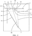
- Fig. 2 illustrates a detection scenario where the device 10 is located remotely (illustrated by the letter “A") from the vehicle 12 (illustrated by the letter “O").
- a Cartesian coordinate system i.e., an X-axis 32 and a Y-axis 34
- the controller-circuit 30 determines a first-range 36A between the first-position 28A of the device 10 and the vehicle 12 based on a first-intensity 16A (see Fig. 1 ) of the homing-signal 18 using the RSSI as described above.
- a first-intensity 16A see Fig. 1
- the homing-signal 18 is broadcast from a transmitter (not shown) located on the vehicle 12.
- the homing-signal 18 is broadcast from a transmitter located proximate to the vehicle 12 (e.g. from a parking meter or light-post near the vehicle 12).
- the vehicle 12 may be in a sleep-mode where the transmitter is not transmitting the homing-signal 18 continuously and is waiting for a wake-up command received by the device 10 to begin transmitting. This has the benefit of conserving battery power.
- the controller-circuit 30 determines whether the receiver 14 receives an initial-homing-signal 18A (i.e.
- controller-circuit 30 designates the first-position 28A in accordance with the determination that the receiver 14 receives the initial-homing-signal 18A (see Fig. 1 ).
- the controller-circuit 30 determines whether the first-intensity 16A of the homing-signal 18 is greater than an intensity-threshold 38 (see Fig. 1 ), whereby the controller-circuit 30 designates the first-position 28A in accordance with the determination that the first-intensity 16A of the homing-signal 18 is greater than the intensity-threshold 38.
- the intensity-threshold 38 may be a user defined level of RSSI and may be a function of the selected transmitter and receiver 14 hardware.
- the controller-circuit 30 determines whether the first-intensity 16A of the homing-signal 18 varies less than a variation-threshold 40 (see Fig. 1 ) for a time greater than a time-threshold 42 (see Fig. 1 ), whereby the controller-circuit 30 designates the first-position 28A in accordance with the determination that the first-intensity 16A of the homing-signal 18 varies less than the variation-threshold 40 (i.e. a variation of the intensity 16 of the homing-signal 18) for the time greater than the time-threshold 42.
- the variation-threshold 40 and the time-threshold 42 may be user defined and may be a function of the selected transmitter and receiver 14 hardware.
- the variation-threshold 40 and the time-threshold 42 may be predefined and stored in the memory of the controller-circuit 30, or may be dynamic and based on factors including a density of other-vehicles and/or a density of structures in a particular area of the vehicle 12 (e.g. an urban area versus a rural area).
- the controller-circuit 30 determines whether the device 10 has moved to a second-position 28B (illustrated by the letter "B") based on a first-distance 22A moved by the device 10 (illustrated by "d 1 ") and a first-heading 26A indicating the direction the device 10 has moved (illustrated by an arrow). That is, the first-distance 22A is measured between the first-position 28A at coordinates (0,0) and the second-position 28B at coordinates (d 1 ,0), and the first-heading 26A is measured as the device 10 moves from the first-position 28A to the second-position 28B.
- a second-position 28B illustrated by the letter "B”
- the first-heading 26A defines the X-axis 32, such that the second-position 28B is located on the X-axis 32 (i.e. the y-coordinate is zero). While defining the X-axis 32 by the first-heading 26A simplifies the geometry used to determine the coordinates of the second-position 28B, the device 10 may optionally establish a fixed Cartesian coordinate system that may be referenced to other coordinate systems, such as a world coordinate system.
- the controller-circuit 30 determines whether the first-distance 22A is greater than a distance-threshold 44 (about 0.5-meters), whereby the controller-circuit 30 designates the second-position 28B in accordance with the determination that the first-distance 22A is greater than the distance-threshold 44.
- the distance-threshold 44 may be user defined and may be based on a resolution of the transmitter and the receiver 14.
- the controller-circuit 30 determines whether the second-intensity 16B of the homing-signal 18 is greater than the intensity-threshold 38, whereby the controller-circuit 30 designates the second-position 28B in accordance with the determination that the second-intensity 16B of the homing-signal 18 is greater than the intensity-threshold 38. In accordance with the determination that the device 10 has moved to the second-position 28B, the controller-circuit 30 determines a second-range 36B between the second-position 28B and the vehicle 12 based on a second-intensity 16B of the homing-signal 18.
- the controller-circuit 30 determines whether the device 10 has moved to a third-position 28C (illustrated by the letter "C") based on the a second-distance 22B (illustrated by "d 2 ”) and a second-heading 26B (illustrated by another arrow). That is, the second-distance 22B is measured between the second-position 28B at coordinates (d 1 ,0) and the third-position 28C at coordinates (d 1 +d 2 cos ⁇ 1 , -d 2 sin ⁇ 1 ), and the second-heading 26B is measured as the device 10 moves from the second-position 28B to the third-position 28C.
- the controller-circuit 30 determines an angle ⁇ 1 based on a difference between the first-heading 26A and the second-heading 26B. In another embodiment, the controller-circuit 30 determines whether the second-distance 22B is greater than the distance-threshold 44, whereby the controller-circuit 30 designates the third-position 28C in accordance with the determination that the second-distance 22B is greater than the distance-threshold 44.
- the controller-circuit 30 determines whether the third-intensity 16C of the homing-signal 18 is greater than the intensity-threshold 38, whereby the controller-circuit 30 designates the third-position 28C in accordance with the determination that the third-intensity 16C of the homing-signal 18 is greater than the intensity-threshold 38. In accordance with the determination that the device 10 has moved to the third-position 28C, the controller-circuit 30 determines a third-range 36C between the third-position 28C and the vehicle 12 based on a third-intensity 16C of the homing-signal 18.
- Fig. 3 illustrates three circles drawn on the Cartesian coordinate system of Fig. 2 , where the centers of each of the circles are placed at the coordinates of the first-position 28A, the second-position 28B, and the third-position 28C.
- the respective radii of the each of the three circles are indicated by the first-range 36A, the second-range 36B, and the third-range 36C.
- the controller-circuit 30 determines a travel-distance 46 and a travel-direction 48 from the device 10 to the vehicle 12 based on the first-range 36A, the second-range 36B, the third-range 36C, the first-distance 22A, the second-distance 22B, the first-heading 26A, and the second-heading 26B using the known process of trilateration.
- the third-range 36C is the travel-distance 46.
- the location of the vehicle 12 is a point where all three of the circles intersect, and the travel-direction 48 is determined based on the coordinates where the three circles intersect.
- the device 10 further includes a clock 50 in communication with the controller-circuit 30, and the homing-signal 18 includes a time-stamp 52 indicative of a time-of-transmission 54 indicated by the clock 50 that the homing-signal 18 was transmitted from the vehicle 12.
- the controller-circuit 30 determines the first-range 36A, the second-range 36B, and the third-range 36C based on a difference between the time-of-transmission 54 and a time-of-receipt 56 of the homing-signal 18 received by the receiver 14.
- the clock 50 is hard-wired to the controller-circuit 30 and is synchronized with the vehicle 12 by any of the known clock-synchronization methods.
- the clock 50 resides in an external infrastructure, such as a cellular transmission station or a satellite, and is in wireless communication with the controller-circuit 30 and the vehicle 12.
- the device 10 further includes a visual-display 58 in communication with the controller-circuit 30, whereby both the travel-distance 46 and the travel-direction 48 to the vehicle 12 are displayed on the visual-display 58 for the user to follow.
- the visual-display 58 may be any visual-display 58 used in mobile-devices. In the example illustrated in Fig. 1 , the visual-display 58 is hard-wired to the controller-circuit 30. In another embodiment the visual-display 58 is in wireless communication with the controller-circuit 30 and is remote from the device 10.
- the device 10 further includes an audible-device 60 in communication with the controller-circuit 30, whereby both the travel-distance 46 and the travel-direction 48 to the vehicle 12 are transmitted through the audible-device 60 for the user to follow.
- the audible-device 60 may be any audible-device 60 used in mobile-devices.
- the audible-device 60 is hard-wired to the controller-circuit 30.
- the audible-device 60 is in wireless communication with the controller-circuit 30.
- the device 10 further includes a haptic-device 62 configured to be worn on a body of a user in communication with the controller-circuit 30, whereby both the travel-distance 46 and the travel-direction 48 to the vehicle 12 are transmitted through the haptic-device 62 to the body of the user and may be useful for a visually impaired user to follow directions to the vehicle 12.
- a haptic-device 62 configured to be worn on a body of a user in communication with the controller-circuit 30, whereby both the travel-distance 46 and the travel-direction 48 to the vehicle 12 are transmitted through the haptic-device 62 to the body of the user and may be useful for a visually impaired user to follow directions to the vehicle 12.
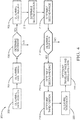
- Fig. 4 is a flow chart illustrating another embodiment of a detection method 200, hereafter referred to as the method 200, for using the detection device 10 of Fig. 1 , hereafter referred to as the device 10, configured to assist a user to locate a vehicle 12.
- Step 202 DETERMINE FIRST-POSITION, includes determining a first-position 28A of the device 10 with a controller-circuit 30 as illustrated in Fig. 2 .
- the controller-circuit 30 determines the first-position 28A when a receiver 14 receives an initial-homing-signal 18A as described above.
- Step 204 DETERMINE FIRST-RANGE, includes determining, with the controller-circuit 30, a first-range 36A between the first-position 28A of the device 10 and the vehicle 12 based on a first-intensity 16A of the homing-signal 18 received by a receiver 14 using RSSI as described above.
- Step 206 DETERMINE MOVEMENT, includes determining, with the controller-circuit 30, whether the device 10 has moved based on signals received by an inertial-measurement-unit 20 (IMU 20) in communication with the controller-circuit 30 as described above.
- IMU 20 inertial-measurement-unit 20
- Step 208, DETERMINE FIRST-HEADING includes determining, with the controller-circuit 30, a first-heading 26A indicating the direction the device 10 has moved based on signals received from an electronic-compass 24 in communication with the controller-circuit 30 as described above.
- Step 210 DETERMINE SECOND-POSITION, includes determining, with the controller-circuit 30, whether the device 10 has moved to a second-position 28B based on a first-distance 22A moved by the device 10 based on signals received by the IMU 20 as described above.
- the controller-circuit 30 designates the second-position 28B in accordance with the determination that the first-distance 22A is greater than a distance-threshold 44.
- the controller-circuit 30 designates the second-position 28B in accordance with the determination that a second-intensity 16B of the homing-signal 18 is greater than an intensity-threshold 38.
- Step 212 DETERMINE SECOND-RANGE, includes determining, with the controller-circuit 30, a second-range 36B between the second-position 28B of the device 10 and the vehicle 12 based on a second-intensity 16B of the homing-signal 18 received by a receiver 14 using RSSI as described above.
- Step 214 DETERMINE MOVEMENT, includes determining, with the controller-circuit 30, whether the device 10 has moved based on signals received by the IMU 20 in communication with the controller-circuit 30.
- Step 216 DETERMINE SECOND-HEADING, includes determining, with the controller-circuit 30, a second-heading 26B indicating the direction the device 10 has moved based on signals received from the electronic-compass 24 as described above.
- Step 218, DETERMINE THIRD-POSITION includes determining, with the controller-circuit 30, whether the device 10 has moved to a third-position 28C based on the a second-distance 22B moved by the device 10 from signals received by the IMU 20, and based on the second-heading 26B as described above.
- the controller-circuit 30 designates the third-position 28C in accordance with the determination that the second-distance 22B is greater than the distance-threshold 44.
- the controller-circuit 30 designates the third-position 28C in accordance with the determination that the third-intensity 16C of the homing-signal 18 is greater than the intensity-threshold 38.
- Step 220 DETERMINE THIRD-RANGE, includes determining, with the controller-circuit 30, a third-range 36C between the third-position 28C and the vehicle 12 based on a third-intensity 16C of the homing-signal 18 received by a receiver 14 using RSSI as described above.
- Step 222 DETERMINE TRAVEL-DISTANCE & TRAVEL-DIRECTION, includes determining, with the controller-circuit 30, both the a travel-distance 46 and a travel-direction 48 from the device 10 to the vehicle 12 based on the first-range 36A, the second-range 36B, the third-range 36C, the first-distance 22A, the second-distance 22B, the first-heading 26A, and the second-heading 26B using the known process of trilateration.
- the location of the vehicle 12 is a point where all three of the circles intersect, and the travel-direction 48 is determined based on the coordinates where the three circles intersect as illustrated in Fig. 3 .
- a first device includes one or more processors, memory, and one or more programs stored in memory.
- the one or more programs including instructions for performing the method described herein.
- a non-transitory computer-readable storage-medium comprising one or more programs for execution by one or more processors of a first device, the one or more programs including instructions which, when executed by the one or more processors, cause the first device to perform the method described herein.
- a detection device 10 (the device 10) and a method 200 of using the device 10 are provided.
- the device 10 is an improvement over prior art detection-devices because the device 10 directs the user back to the vehicle 12 without the use of GPS satellites and/or without requiring the device 10 to remember a path taken from the vehicle 12.
- first contact could be termed a second contact
- second contact could be termed a first contact
- the first contact and the second contact are both contacts, but they are not the same contact.
- the terminology used in the description of the various described embodiments herein is for the purpose of describing particular embodiments only and is not intended to be limiting. As used in the description of the various described embodiments and the appended claims, the singular forms "a”, “an” and “the” are intended to include the plural forms as well, unless the context clearly indicates otherwise. It will also be understood that the term “and/or” as used herein refers to and encompasses any and all possible combinations of one or more of the associated listed items.
- the phrase “if it is determined” or “if [a stated condition or event] is detected” is, optionally, construed to mean “upon determining” or “in response to determining” or “upon detecting [the stated condition or event]” or “in response to detecting [the stated condition or event],” depending on the context.
Landscapes
- Engineering & Computer Science (AREA)
- Remote Sensing (AREA)
- Radar, Positioning & Navigation (AREA)
- Physics & Mathematics (AREA)
- General Physics & Mathematics (AREA)
- Automation & Control Theory (AREA)
- Electromagnetism (AREA)
- Computer Networks & Wireless Communication (AREA)
- Environmental & Geological Engineering (AREA)
- General Life Sciences & Earth Sciences (AREA)
- Geology (AREA)
- Life Sciences & Earth Sciences (AREA)
- Position Fixing By Use Of Radio Waves (AREA)
- Navigation (AREA)
Abstract
Description
- This application claims the benefit of
U.S. Provisional Patent Application No. 62/671,768, filed May 15, 2018 U.S. Patent Application No. 15/980,809, filed May 16, 2018 - This disclosure generally relates to a location device, and more particularly relates to a vehicle location device.
- The present invention will now be described, by way of example with reference to the accompanying drawings, in which:
-
Fig. 1 illustrates a detection device in accordance with one embodiment; -
Fig. 2 illustrates a Cartesian coordinate system determined using the detection device ofFig. 1 to locate a vehicle in accordance with one embodiment; -
Fig. 3 illustrates a trilateration process using the Cartesian coordinate system ofFig. 2 in accordance with one embodiment; and -
Fig. 4 is a flow chart illustrating a method of using the detection device ofFig. 1 in accordance with another embodiment. - Reference will now be made in detail to embodiments, examples of which are illustrated in the accompanying drawings. In the following detailed description, numerous specific details are set forth in order to provide a thorough understanding of the various described embodiments. However, it will be apparent to one of ordinary skill in the art that the various described embodiments may be practiced without these specific details. In other instances, well-known methods, procedures, components, circuits, and networks have not been described in detail so as not to unnecessarily obscure aspects of the embodiments.
-
Fig. 1 illustrates adetection device 10, hereafter referred to as thedevice 10, configured to assist a user to locate avehicle 12. In the examples described herein, thedevice 10 is amobile device 10 that is carried by the user while the user is away from thevehicle 12. As will be described in more detail below, thedevice 10 is an improvement over other detection-devices, because thedevice 10 directs the user back to thevehicle 12 without the use of GPS satellites, cellular network, and/or without requiring thedevice 10 to remember a path taken from thevehicle 12. - The
device 10 includes areceiver 14 determiningintensity 16 of a homing-signal 18 transmitted from thevehicle 12 and received at thedevice 10. Thereceiver 14 is anyreceiver 14 capable of receiving the homing-signal 18 that conforms to an IEEE 802.15.1- BLUETOOTH® 5.0 LE specification. In thedevice 10 illustrated inFig. 1 , theintensity 16 of the homing-signal 18 is determined by the known method of received signal strength indicator (RSSI). In the example illustrated inFig. 1 , the homing-signal 18 is received by asingle receiver 14. - The
device 10 also includes an inertial-measurement-unit 20 (IMU 20) determining adistance 22 thedevice 10 is moved. The IMU 20 may be any of the known IMU's 20 that are used typically in smartphones and/or other mobile-devices, such as electronic pedometers. - The
device 10 also includes an electronic-compass 24 determining aheading 26 in which thedevice 10 is moving (i.e. a direction of travel). That is, the electronic-compass 24 determines theheading 26 as thedevice 10 is moved from oneposition 28 to anotherposition 28. The electronic-compass 24 may be any known electronic-compass 24 that utilizes a magnetometer, such as a MEMS magnetic field sensor. - The
device 10 also includes a controller-circuit 30 in communication with thereceiver 14, theIMU 20, and the electronic-compass 24. Thereceiver 14, theIMU 20, and the electronic-compass 24 may be hard-wired to the controller-circuit 30, or may be in wireless communication with the controller-circuit 30. The controller-circuit 30 may include a processor (not shown) such as a microprocessor or other control circuitry such as analog and/or digital control circuitry including an application specific integrated circuit (ASIC) for processing data as should be evident to those in the art. The controller-circuit 30 may include a memory (not specifically shown), including non-volatile memory, such as electrically erasable programmable read-only memory (EEPROM) for storing one or more routines, thresholds, and captured data. The one or more routines may be executed by the processor to perform steps for determining theintensity 16, theheading 26, and theposition 28 based on signals received by the controller-circuit 30 from thereceiver 14, theIMU 20, and the electronic-compass 24, as described herein. -
Fig. 2 illustrates a detection scenario where thedevice 10 is located remotely (illustrated by the letter "A") from the vehicle 12 (illustrated by the letter "O"). A Cartesian coordinate system (i.e., anX-axis 32 and a Y-axis 34) is established by the controller-circuit 30 with first-position 28A of thedevice 10 defined by coordinates (0,0). The controller-circuit 30 determines a first-range 36A between the first-position 28A of thedevice 10 and thevehicle 12 based on a first-intensity 16A (seeFig. 1 ) of the homing-signal 18 using the RSSI as described above. In the examples illustrated inFigs. 1-2 , the homing-signal 18 is broadcast from a transmitter (not shown) located on thevehicle 12. In another embodiment the homing-signal 18 is broadcast from a transmitter located proximate to the vehicle 12 (e.g. from a parking meter or light-post near the vehicle 12). In another embodiment, thevehicle 12 may be in a sleep-mode where the transmitter is not transmitting the homing-signal 18 continuously and is waiting for a wake-up command received by thedevice 10 to begin transmitting. This has the benefit of conserving battery power. The controller-circuit 30 determines whether thereceiver 14 receives an initial-homing-signal 18A (i.e. a first occurrence of a receipt of the homing-signal 18), whereby the controller-circuit 30 designates the first-position 28A in accordance with the determination that thereceiver 14 receives the initial-homing-signal 18A (seeFig. 1 ). - In another embodiment, the controller-
circuit 30 determines whether the first-intensity 16A of the homing-signal 18 is greater than an intensity-threshold 38 (seeFig. 1 ), whereby the controller-circuit 30 designates the first-position 28A in accordance with the determination that the first-intensity 16A of the homing-signal 18 is greater than the intensity-threshold 38. The intensity-threshold 38 may be a user defined level of RSSI and may be a function of the selected transmitter andreceiver 14 hardware. - In yet another embodiment, the controller-
circuit 30 determines whether the first-intensity 16A of the homing-signal 18 varies less than a variation-threshold 40 (seeFig. 1 ) for a time greater than a time-threshold 42 (seeFig. 1 ), whereby the controller-circuit 30 designates the first-position 28A in accordance with the determination that the first-intensity 16A of the homing-signal 18 varies less than the variation-threshold 40 (i.e. a variation of theintensity 16 of the homing-signal 18) for the time greater than the time-threshold 42. The variation-threshold 40 and the time-threshold 42 may be user defined and may be a function of the selected transmitter andreceiver 14 hardware. The variation-threshold 40 and the time-threshold 42 may be predefined and stored in the memory of the controller-circuit 30, or may be dynamic and based on factors including a density of other-vehicles and/or a density of structures in a particular area of the vehicle 12 (e.g. an urban area versus a rural area). - Referring back to
Fig. 2 , in accordance with the determination of the first-range 36A, the controller-circuit 30 determines whether thedevice 10 has moved to a second-position 28B (illustrated by the letter "B") based on a first-distance 22A moved by the device 10 (illustrated by "d1") and a first-heading 26A indicating the direction thedevice 10 has moved (illustrated by an arrow). That is, the first-distance 22A is measured between the first-position 28A at coordinates (0,0) and the second-position 28B at coordinates (d1,0), and the first-heading 26A is measured as thedevice 10 moves from the first-position 28A to the second-position 28B. In the example illustrated inFig. 2 , the first-heading 26A defines theX-axis 32, such that the second-position 28B is located on the X-axis 32 (i.e. the y-coordinate is zero). While defining theX-axis 32 by the first-heading 26A simplifies the geometry used to determine the coordinates of the second-position 28B, thedevice 10 may optionally establish a fixed Cartesian coordinate system that may be referenced to other coordinate systems, such as a world coordinate system. In another embodiment, the controller-circuit 30 determines whether the first-distance 22A is greater than a distance-threshold 44 (about 0.5-meters), whereby the controller-circuit 30 designates the second-position 28B in accordance with the determination that the first-distance 22A is greater than the distance-threshold 44. The distance-threshold 44 may be user defined and may be based on a resolution of the transmitter and thereceiver 14. In another embodiment the controller-circuit 30 determines whether the second-intensity 16B of the homing-signal 18 is greater than the intensity-threshold 38, whereby the controller-circuit 30 designates the second-position 28B in accordance with the determination that the second-intensity 16B of the homing-signal 18 is greater than the intensity-threshold 38. In accordance with the determination that thedevice 10 has moved to the second-position 28B, the controller-circuit 30 determines a second-range 36B between the second-position 28B and thevehicle 12 based on a second-intensity 16B of the homing-signal 18. - In accordance with the determination of the second-
range 36B, the controller-circuit 30 determines whether thedevice 10 has moved to a third-position 28C (illustrated by the letter "C") based on the a second-distance 22B (illustrated by "d2") and a second-heading 26B (illustrated by another arrow). That is, the second-distance 22B is measured between the second-position 28B at coordinates (d1,0) and the third-position 28C at coordinates (d1+d2cosθ1, -d2sinθ1), and the second-heading 26B is measured as thedevice 10 moves from the second-position 28B to the third-position 28C. The controller-circuit 30 determines an angle θ1 based on a difference between the first-heading 26A and the second-heading 26B. In another embodiment, the controller-circuit 30 determines whether the second-distance 22B is greater than the distance-threshold 44, whereby the controller-circuit 30 designates the third-position 28C in accordance with the determination that the second-distance 22B is greater than the distance-threshold 44. In another embodiment, the controller-circuit 30 determines whether the third-intensity 16C of the homing-signal 18 is greater than the intensity-threshold 38, whereby the controller-circuit 30 designates the third-position 28C in accordance with the determination that the third-intensity 16C of the homing-signal 18 is greater than the intensity-threshold 38. In accordance with the determination that thedevice 10 has moved to the third-position 28C, the controller-circuit 30 determines a third-range 36C between the third-position 28C and thevehicle 12 based on a third-intensity 16C of the homing-signal 18. -
Fig. 3 illustrates three circles drawn on the Cartesian coordinate system ofFig. 2 , where the centers of each of the circles are placed at the coordinates of the first-position 28A, the second-position 28B, and the third-position 28C. The respective radii of the each of the three circles are indicated by the first-range 36A, the second-range 36B, and the third-range 36C. The controller-circuit 30 determines a travel-distance 46 and a travel-direction 48 from thedevice 10 to thevehicle 12 based on the first-range 36A, the second-range 36B, the third-range 36C, the first-distance 22A, the second-distance 22B, the first-heading 26A, and the second-heading 26B using the known process of trilateration. In the example illustrated inFig. 3 , the third-range 36C is the travel-distance 46. The location of thevehicle 12 is a point where all three of the circles intersect, and the travel-direction 48 is determined based on the coordinates where the three circles intersect. - Referring again to
Fig. 1 , in another embodiment thedevice 10 further includes aclock 50 in communication with the controller-circuit 30, and the homing-signal 18 includes a time-stamp 52 indicative of a time-of-transmission 54 indicated by theclock 50 that the homing-signal 18 was transmitted from thevehicle 12. The controller-circuit 30 determines the first-range 36A, the second-range 36B, and the third-range 36C based on a difference between the time-of-transmission 54 and a time-of-receipt 56 of the homing-signal 18 received by thereceiver 14. In the example illustrated inFig. 1 , theclock 50 is hard-wired to the controller-circuit 30 and is synchronized with thevehicle 12 by any of the known clock-synchronization methods. In another embodiment, theclock 50 resides in an external infrastructure, such as a cellular transmission station or a satellite, and is in wireless communication with the controller-circuit 30 and thevehicle 12. - In another embodiment, the
device 10 further includes a visual-display 58 in communication with the controller-circuit 30, whereby both the travel-distance 46 and the travel-direction 48 to thevehicle 12 are displayed on the visual-display 58 for the user to follow. The visual-display 58 may be any visual-display 58 used in mobile-devices. In the example illustrated inFig. 1 , the visual-display 58 is hard-wired to the controller-circuit 30. In another embodiment the visual-display 58 is in wireless communication with the controller-circuit 30 and is remote from thedevice 10. - In another embodiment, the
device 10 further includes an audible-device 60 in communication with the controller-circuit 30, whereby both the travel-distance 46 and the travel-direction 48 to thevehicle 12 are transmitted through the audible-device 60 for the user to follow. The audible-device 60 may be any audible-device 60 used in mobile-devices. In the example illustrated inFig. 1 , the audible-device 60 is hard-wired to the controller-circuit 30. In another embodiment the audible-device 60 is in wireless communication with the controller-circuit 30. - In an alternative embodiment, the
device 10 further includes a haptic-device 62 configured to be worn on a body of a user in communication with the controller-circuit 30, whereby both the travel-distance 46 and the travel-direction 48 to thevehicle 12 are transmitted through the haptic-device 62 to the body of the user and may be useful for a visually impaired user to follow directions to thevehicle 12. -
Fig. 4 is a flow chart illustrating another embodiment of adetection method 200, hereafter referred to as themethod 200, for using thedetection device 10 ofFig. 1 , hereafter referred to as thedevice 10, configured to assist a user to locate avehicle 12. -
Step 202, DETERMINE FIRST-POSITION, includes determining a first-position 28A of thedevice 10 with a controller-circuit 30 as illustrated inFig. 2 . The controller-circuit 30 determines the first-position 28A when areceiver 14 receives an initial-homing-signal 18A as described above. -
Step 204, DETERMINE FIRST-RANGE, includes determining, with the controller-circuit 30, a first-range 36A between the first-position 28A of thedevice 10 and thevehicle 12 based on a first-intensity 16A of the homing-signal 18 received by areceiver 14 using RSSI as described above. -
Step 206, DETERMINE MOVEMENT, includes determining, with the controller-circuit 30, whether thedevice 10 has moved based on signals received by an inertial-measurement-unit 20 (IMU 20) in communication with the controller-circuit 30 as described above. -
Step 208, DETERMINE FIRST-HEADING, includes determining, with the controller-circuit 30, a first-heading 26A indicating the direction thedevice 10 has moved based on signals received from an electronic-compass 24 in communication with the controller-circuit 30 as described above. -
Step 210, DETERMINE SECOND-POSITION, includes determining, with the controller-circuit 30, whether thedevice 10 has moved to a second-position 28B based on a first-distance 22A moved by thedevice 10 based on signals received by theIMU 20 as described above. In one embodiment, the controller-circuit 30 designates the second-position 28B in accordance with the determination that the first-distance 22A is greater than a distance-threshold 44. In another embodiment, the controller-circuit 30 designates the second-position 28B in accordance with the determination that a second-intensity 16B of the homing-signal 18 is greater than an intensity-threshold 38. -
Step 212, DETERMINE SECOND-RANGE, includes determining, with the controller-circuit 30, a second-range 36B between the second-position 28B of thedevice 10 and thevehicle 12 based on a second-intensity 16B of the homing-signal 18 received by areceiver 14 using RSSI as described above. -
Step 214, DETERMINE MOVEMENT, includes determining, with the controller-circuit 30, whether thedevice 10 has moved based on signals received by theIMU 20 in communication with the controller-circuit 30. -
Step 216, DETERMINE SECOND-HEADING, includes determining, with the controller-circuit 30, a second-heading 26B indicating the direction thedevice 10 has moved based on signals received from the electronic-compass 24 as described above. -
Step 218, DETERMINE THIRD-POSITION, includes determining, with the controller-circuit 30, whether thedevice 10 has moved to a third-position 28C based on the a second-distance 22B moved by thedevice 10 from signals received by theIMU 20, and based on the second-heading 26B as described above. In one embodiment, the controller-circuit 30 designates the third-position 28C in accordance with the determination that the second-distance 22B is greater than the distance-threshold 44. In another embodiment, the controller-circuit 30 designates the third-position 28C in accordance with the determination that the third-intensity 16C of the homing-signal 18 is greater than the intensity-threshold 38. -
Step 220, DETERMINE THIRD-RANGE, includes determining, with the controller-circuit 30, a third-range 36C between the third-position 28C and thevehicle 12 based on a third-intensity 16C of the homing-signal 18 received by areceiver 14 using RSSI as described above. -
Step 222, DETERMINE TRAVEL-DISTANCE & TRAVEL-DIRECTION, includes determining, with the controller-circuit 30, both the a travel-distance 46 and a travel-direction 48 from thedevice 10 to thevehicle 12 based on the first-range 36A, the second-range 36B, the third-range 36C, the first-distance 22A, the second-distance 22B, the first-heading 26A, and the second-heading 26B using the known process of trilateration. The location of thevehicle 12 is a point where all three of the circles intersect, and the travel-direction 48 is determined based on the coordinates where the three circles intersect as illustrated inFig. 3 . - In another embodiment, a first device includes one or more processors, memory, and one or more programs stored in memory. The one or more programs including instructions for performing the method described herein.
- In another embodiment, a non-transitory computer-readable storage-medium comprising one or more programs for execution by one or more processors of a first device, the one or more programs including instructions which, when executed by the one or more processors, cause the first device to perform the method described herein.
- Accordingly, a detection device 10 (the device 10) and a
method 200 of using thedevice 10 are provided. Thedevice 10 is an improvement over prior art detection-devices because thedevice 10 directs the user back to thevehicle 12 without the use of GPS satellites and/or without requiring thedevice 10 to remember a path taken from thevehicle 12. - While this invention has been described in terms of the preferred embodiments thereof, it is not intended to be so limited, but rather only to the extent set forth in the claims that follow. "One or more" includes a function being performed by one element, a function being performed by more than one element, e.g., in a distributed fashion, several functions being performed by one element, several functions being performed by several elements, or any combination of the above. It will also be understood that, although the terms first, second, etc. are, in some instances, used herein to describe various elements, these elements should not be limited by these terms. These terms are only used to distinguish one element from another. For example, a first contact could be termed a second contact, and, similarly, a second contact could be termed a first contact, without departing from the scope of the various described embodiments. The first contact and the second contact are both contacts, but they are not the same contact. The terminology used in the description of the various described embodiments herein is for the purpose of describing particular embodiments only and is not intended to be limiting. As used in the description of the various described embodiments and the appended claims, the singular forms "a", "an" and "the" are intended to include the plural forms as well, unless the context clearly indicates otherwise. It will also be understood that the term "and/or" as used herein refers to and encompasses any and all possible combinations of one or more of the associated listed items. It will be further understood that the terms "includes," "including," "comprises," and/or "comprising," when used in this specification, specify the presence of stated features, integers, steps, operations, elements, and/or components, but do not preclude the presence or addition of one or more other features, integers, steps, operations, elements, components, and/or groups thereof. As used herein, the term "if' is, optionally, construed to mean "when" or "upon" or "in response to determining" or "in response to detecting," depending on the context. Similarly, the phrase "if it is determined" or "if [a stated condition or event] is detected" is, optionally, construed to mean "upon determining" or "in response to determining" or "upon detecting [the stated condition or event]" or "in response to detecting [the stated condition or event]," depending on the context.
Claims (15)
- A detection device (10), said device (10) comprising:a receiver (14), the receiver (14) determining intensity (16) of a homing-signal (18) transmitted from a vehicle (12) and received at the device (10);an inertial-measurement-unit (20), the inertial-measurement-unit (20) determining a distance (22) the device (10) is moved;an electronic-compass (24), the electronic-compass (24) determining a heading in which the device (10) is moving; anda controller-circuit (30) in communication with the receiver (14), the inertial-measurement-unit (20), and the electronic-compass (24), the controller-circuit (30) determining a first-range (36A) between a first-position (28A) of the device (10) and the vehicle (12) based on a first-intensity (16A) of the homing-signal (18);in accordance with the determination of the first-range (36A), the controller-circuit (30) determining whether the device (10) has moved to a second-position (28B) based on a first-distance (22A) and a first-heading (26A);in accordance with the determination that the device (10) has moved to the second-position (28B), the controller-circuit (30) determining a second-range (36B) between the second-position (28B) and the vehicle (12) based on a second-intensity (16B) of the homing-signal (18);in accordance with the determination of the second-range (36B), the controller-circuit (30) determining whether the device (10) has moved to a third-position (28C) based on the a second-distance (22B) and a second-heading (26B);in accordance with the determination that the device (10) has moved to the third-position (28C), the controller-circuit (30) determining a third-range (36C) between the third-position (28C) and the vehicle (12) based on a third-intensity (16C) of the homing-signal (18); whereinthe controller-circuit (30) determines a travel-distance (46) and a travel-direction (48) from the device (10) to the vehicle (12) based on the first-range (36A), the second-range (36B), the third-range (36C), the first-distance (22A), the second-distance (22B), the first-heading (26A), and the second-heading (26B).
- The device (10) in accordance with claim 1, wherein the device (10) further includes a clock (50) in communication with the controller-circuit (30), and wherein the homing-signal (18) includes a time-stamp (52) indicative of a time-of-transmission (54) indicated by the clock (50) that the homing-signal (18) was transmitted from the vehicle (12), whereby the controller-circuit (30) determines the first-range (36A), the second-range (36B), and the third-range (36C) based on a difference between the time-of-transmission (54) and a time-of-receipt (56) of the homing-signal (18) received by the receiver (14).
- The device (10) in accordance with any one of the preceding claims, wherein the controller-circuit (30) determines whether the receiver (14) receives an initial-homing-signal (18A), whereby the controller-circuit (30) designates the first-position (28A) in accordance with the determination that the receiver (14) receives the initial-homing-signal (18A).
- The device (10) in accordance with any one of the preceding claims, wherein the controller-circuit (30) determines whether the first-intensity (16A) of the homing-signal (18) is greater than an intensity-threshold (38), whereby the controller-circuit (30) designates the first-position (28A) in accordance with the determination that the first-intensity (16A) of the homing-signal (18) is greater than the intensity-threshold (38).
- The device (10) in accordance with any one of the preceding claims, wherein the controller-circuit (30) determines whether the first-intensity (16A) of the homing-signal (18) varies less than a variation-threshold (40) for a time greater than a time-threshold (42), whereby the controller-circuit (30) designates the first-position (28A) in accordance with the determination that the first-intensity (16A) of the homing-signal (18) varies less than the variation-threshold (40) for the time greater than the time-threshold (42).
- The device (10) in accordance with any one of the preceding claims, wherein the controller-circuit (30) determines whether the first-distance (22A) is greater than a distance-threshold (44), whereby the controller-circuit (30) designates the second-position (28B) in accordance with the determination that the first-distance (22A) is greater than the distance-threshold (44).
- The device (10) in accordance with claim 6, wherein the controller-circuit (30) determines whether the second-intensity (16B) of the homing-signal (18) is greater than an intensity-threshold (38), whereby the controller-circuit (30) designates the second-position (28B) in accordance with the determination that the second-intensity (16B) of the homing-signal (18) is greater than the intensity-threshold (38).
- The device (10) in accordance with any one of the preceding claims, wherein the controller-circuit (30) determines whether the second-distance (22B) is greater than a distance-threshold (44), whereby the controller-circuit (30) designates the third-position (28C) in accordance with the determination that the second-distance (22B) is greater than the distance-threshold (44).
- The device (10) in accordance with claim 8, wherein the controller-circuit (30) determines whether the third-intensity (16C) of the homing-signal (18) is greater than an intensity-threshold (38), whereby the controller-circuit (30) designates the third-position (28C) in accordance with the determination that the third-intensity (16C) of the homing-signal (18) is greater than the intensity-threshold (38).
- The device (10) in accordance with any one of the preceding claims, wherein the homing-signal (18) is received by a single receiver (14).
- The device (10) in accordance with any one of the preceding claims, wherein the device (10) further includes a visual-display (58) in communication with the controller-circuit (30), whereby both the travel-distance (46) and the travel-direction (48) to the vehicle (12) are displayed on the visual-display (58).
- The device (10) in accordance with any one of the preceding claims, wherein the device (10) further includes an audible-device (60) in communication with the controller-circuit (30), whereby both the travel-distance (46) and the travel-direction (48) to the vehicle (12) are transmitted through the audible-device (60).
- A detection method (200), said method (200) comprising:determining (202) an intensity (16) of a homing-signal (18) transmitted from a vehicle (12), with a receiver (14) installed in a device (10);determining (206) a distance (22) the device (10) is moved, with an inertial-measurement-unit (20) installed in the device (10);determining (208) a heading in which the device (10) is moving, with an electronic-compass (24) installed in the device (10);determining (204), with a controller-circuit (30) in communication with the receiver (14), the inertial-measurement-unit (20), and the electronic-compass (24), a first-range (36A) between a first-position (28A) of the device (10) and the vehicle (12) based on a first-intensity (16A) of the homing-signal (18);in accordance with the determination of the first-range (36A), determining (206) with the controller-circuit (30) whether the device (10) has moved to a second-position (28B) based on a first-distance (22A) and a first-heading (26A);in accordance with the determination that the device (10) has moved to the second-position (28B), determining (212) with the controller-circuit (30) a second-range (36B) between the second-position (28B) and the vehicle (12) based on a second-intensity (16B) of the homing-signal (18);in accordance with the determination of the second-range (36B), determining (214) with the controller-circuit (30) whether the device (10) has moved to a third-position (28C) based on the a second-distance (22B) and a second-heading (26B);in accordance with the determination (218) that the device (10) has moved to the third-position (28C), determining (220) with the controller-circuit (30) a third-range (36C) between the third-position (28C) and the vehicle (12) based on a third-intensity (16C) of the homing-signal (18); anddetermining (222) with the controller-circuit (30) a travel-distance (46) and a travel-direction (48) from the device (10) to the vehicle (12) based on the first-range (36A), the second-range (36B), the third-range (36C), the first-distance (22A), the second-distance (22B), the first-heading (26A), and the second-heading (26B).
- The method (200) in accordance with claim 13, wherein the device (10) further includes a clock (50) in communication with the controller-circuit (30), and wherein the homing-signal (18) includes a time-stamp (52) indicative of a time-of-transmission (54) indicated by the clock (50) that the homing-signal (18) was transmitted from the vehicle (12), further including the step of determining (204, 212, 220), with the controller-circuit (30), the first-range (36A), the second-range (36B), and the third-range (36C) based on a difference between the time-of-transmission (54) and a time-of-receipt (56) of the homing-signal (18) received by the receiver (14).
- The method (200) in accordance with any one of claims 13-14, further including the step of determining (202), with the controller-circuit (30), whether the receiver (14) receives an initial-homing-signal (18A), whereby the controller-circuit (30) designates the first-position (28A) in accordance with the determination that the receiver (14) receives the initial-homing-signal (18A).
Applications Claiming Priority (2)
| Application Number | Priority Date | Filing Date | Title |
|---|---|---|---|
| US201862671768P | 2018-05-15 | 2018-05-15 | |
| US15/980,809 US10317517B1 (en) | 2018-05-15 | 2018-05-16 | Vehicle location device |
Publications (1)
| Publication Number | Publication Date |
|---|---|
| EP3569981A1 true EP3569981A1 (en) | 2019-11-20 |
Family
ID=66767523
Family Applications (1)
| Application Number | Title | Priority Date | Filing Date |
|---|---|---|---|
| EP19171587.9A Pending EP3569981A1 (en) | 2018-05-15 | 2019-04-29 | Vehicle location device |
Country Status (3)
| Country | Link |
|---|---|
| US (2) | US10317517B1 (en) |
| EP (1) | EP3569981A1 (en) |
| CN (2) | CN118981037A (en) |
Families Citing this family (4)
| Publication number | Priority date | Publication date | Assignee | Title |
|---|---|---|---|---|
| US11250653B2 (en) * | 2019-02-13 | 2022-02-15 | Brunswick Corporation | Configurable remote control system and method for a marine vessel |
| US11551322B2 (en) * | 2019-05-03 | 2023-01-10 | The Boeing Company | Methods and devices for searching for a missing person |
| US11598838B2 (en) | 2019-06-26 | 2023-03-07 | Aptiv Technologies Limited | Detection device |
| US20250383206A1 (en) * | 2024-06-12 | 2025-12-18 | Battelle Memorial Institute | Inertial measurement unit-enhanced two-way ranging |
Citations (1)
| Publication number | Priority date | Publication date | Assignee | Title |
|---|---|---|---|---|
| WO2008154747A1 (en) * | 2007-06-19 | 2008-12-24 | Magna Electronics Inc. | Mobile control node system and method for vehicles |
Family Cites Families (52)
| Publication number | Priority date | Publication date | Assignee | Title |
|---|---|---|---|---|
| US5170165A (en) * | 1987-08-07 | 1992-12-08 | Honda Giken Kogyo Kabushiki Kaisha | Apparatus for displaying travel path |
| US6127931A (en) * | 1999-08-16 | 2000-10-03 | Mohr; Robert | Device for monitoring the movement of a person |
| US6297737B1 (en) | 2000-04-03 | 2001-10-02 | Ericsson Inc | Object locating system |
| US6895310B1 (en) | 2000-04-24 | 2005-05-17 | Usa Technologies, Inc. | Vehicle related wireless scientific instrumentation telematics |
| WO2002073562A1 (en) * | 2001-03-12 | 2002-09-19 | Eureka Technologies Partners, Llc | Article locator system |
| US7548491B2 (en) | 2002-06-13 | 2009-06-16 | General Motors Corporation | Personalized key system for a mobile vehicle |
| US6873257B2 (en) * | 2002-07-01 | 2005-03-29 | Craig Maloney | Vehicle location device |
| CA2394770A1 (en) | 2002-07-23 | 2004-01-23 | Boomerang Tracking Inc. | Vehicle location system using a kinetic network |
| US7479889B2 (en) | 2003-10-02 | 2009-01-20 | Ronald S. Kazdin | Locator system |
| US20050099275A1 (en) | 2003-11-06 | 2005-05-12 | Kamdar Hitan S. | Method and system for status indication on a key fob |
| US7877275B2 (en) | 2003-11-13 | 2011-01-25 | General Motors Llc | System and method for maintaining and providing personal information in real time |
| WO2006015418A1 (en) | 2004-08-10 | 2006-02-16 | Australian Arrow Pty Ltd | Bi-directional radio monitoring system |
| KR100645381B1 (en) * | 2005-08-31 | 2006-11-14 | 삼성광주전자 주식회사 | External charge return device and return method for robot cleaner |
| US20070090965A1 (en) * | 2005-10-21 | 2007-04-26 | Mc Call Clark E | Key-fob locating method and apparatus |
| US20070285230A1 (en) | 2006-06-08 | 2007-12-13 | Julia Karen Anglin | Device to help people locate their vehicles fast |
| JP2007334825A (en) | 2006-06-19 | 2007-12-27 | Denso Corp | Vehicle position information notification system. |
| US7696887B1 (en) * | 2006-10-25 | 2010-04-13 | Arturo Echavarria | Person tracking and communication system |
| US8319605B2 (en) | 2007-06-19 | 2012-11-27 | Magna Electronics, Inc. | Remote vehicle control system utilizing multiple antennas |
| US20090091477A1 (en) | 2007-10-08 | 2009-04-09 | Gm Global Technology Operations, Inc. | Vehicle fob with expanded display area |
| US7911337B2 (en) * | 2008-03-07 | 2011-03-22 | Lear Corporation | Compass based car locator |
| US8335598B2 (en) | 2008-09-23 | 2012-12-18 | Lear Corporation | System and method for detecting radio frequency signals and controlling vehicle operations in response thereto |
| US8571725B2 (en) | 2009-01-29 | 2013-10-29 | Trw Automotive U.S. Llc | Apparatus for locating a vehicle electronic key |
| US8723729B2 (en) * | 2009-05-26 | 2014-05-13 | Broadcom Corporation | Angle of arrival and/or range estimation within a wireless communication device |
| US8249802B2 (en) | 2009-08-14 | 2012-08-21 | Honda Motor Co., Ltd. | Vehicle keyless operation system and method |
| US8547253B2 (en) | 2009-09-04 | 2013-10-01 | GM Global Technology Operations LLC | Method of determining vehicle location from key fob |
| US8284020B2 (en) | 2009-12-22 | 2012-10-09 | Lear Corporation | Passive entry system and method for a vehicle |
| US8494447B2 (en) | 2010-07-29 | 2013-07-23 | General Motors Llc | Aftermarket telematics unit for use with a vehicle |
| US8335502B2 (en) | 2010-09-21 | 2012-12-18 | General Motors Llc | Method for controlling mobile communications |
| US20120092129A1 (en) | 2010-10-19 | 2012-04-19 | Honda Motor Co., Ltd. | Method to track vehicle key near vehicle for smart entry |
| KR101907229B1 (en) | 2011-02-03 | 2018-10-11 | 니타 하스 인코포레이티드 | Polishing composition and polishing method using same |
| US8744482B2 (en) | 2011-03-25 | 2014-06-03 | Lear Corporation | Apparatus and method for wireless device detection |
| US8626144B2 (en) | 2011-07-13 | 2014-01-07 | GM Global Technology Operations LLC | Bluetooth low energy approach detections through vehicle paired capable devices |
| US8929192B2 (en) | 2012-01-25 | 2015-01-06 | Nokia Corporation | Method, apparatus, and computer program product for short-range communication based direction finding |
| US20130342379A1 (en) * | 2012-06-25 | 2013-12-26 | Lear Corporation | Vehicle Remote Function System and Method |
| US8798809B2 (en) | 2012-08-21 | 2014-08-05 | GM Global Technology Operations LLC | System for passive entry and passive start using near field communication |
| US9079560B2 (en) | 2012-11-02 | 2015-07-14 | GM Global Technology Operations LLC | Device location determination by a vehicle |
| US9218700B2 (en) | 2012-12-14 | 2015-12-22 | GM Global Technology Operations LLC | Method and system for secure and authorized communication between a vehicle and wireless communication devices or key fobs |
| US9536364B2 (en) * | 2013-02-25 | 2017-01-03 | GM Global Technology Operations LLC | Vehicle integration of BLE nodes to enable passive entry and passive start features |
| US9154920B2 (en) | 2013-03-01 | 2015-10-06 | Lear Corporation | System and method for detecting a location of a wireless device |
| US20140308971A1 (en) * | 2013-04-16 | 2014-10-16 | Lear Corporation | Vehicle System for Detecting a Three-Dimensional Location of a Wireless Device |
| US20150063329A1 (en) | 2013-08-28 | 2015-03-05 | General Motors Llc | Selective vehicle wi-fi access |
| DE102013110280A1 (en) * | 2013-09-18 | 2015-03-19 | Paul Vahle Gmbh & Co. Kg | Positioning system for vehicles |
| US9187061B2 (en) | 2013-10-18 | 2015-11-17 | GM Global Technology Operations LLC | Electronic device finder system |
| US9754431B2 (en) | 2014-08-18 | 2017-09-05 | Livio, Inc. | Method and system for a key fob base station enabling remote car access using a nomadic device |
| US9373256B2 (en) * | 2014-11-06 | 2016-06-21 | Frogparking Limited | Vehicle presence detection system |
| CN104442700B (en) * | 2014-12-02 | 2017-04-26 | 江苏舟航物联网技术有限公司 | Multi-mode car searching method, multi-mode car searching device and multi-mode car searching system |
| US10250073B2 (en) * | 2015-03-22 | 2019-04-02 | Powermat Technologies Ltd. | System and methods of centrally managing a wireless power outlet for powering electrical devices |
| JP6634775B2 (en) * | 2015-10-19 | 2020-01-22 | 富士通株式会社 | Portable terminal device, position search method, and position search program |
| FR3049065B1 (en) * | 2016-03-16 | 2018-03-23 | Continental Automotive France | METHOD FOR DETERMINING THE POSITION OF A PORTABLE USER EQUIPMENT AROUND A VEHICLE AND ASSOCIATED LOCATION DEVICE |
| CN106228836A (en) * | 2016-08-01 | 2016-12-14 | 北京小米移动软件有限公司 | Indoor parking guide method and device |
| US10210760B2 (en) * | 2016-09-21 | 2019-02-19 | Dura Operating, Llc | System and method for autonomous parking of a vehicle |
| US10057728B2 (en) * | 2016-10-12 | 2018-08-21 | Ford Global Technologies, Llc | Method and apparatus for wireless vehicle location assistance |
-
2018
- 2018-05-16 US US15/980,809 patent/US10317517B1/en active Active
-
2019
- 2019-04-29 EP EP19171587.9A patent/EP3569981A1/en active Pending
- 2019-04-30 US US16/399,002 patent/US10641880B2/en active Active
- 2019-05-10 CN CN202411097942.6A patent/CN118981037A/en active Pending
- 2019-05-10 CN CN201910389327.5A patent/CN110488336B/en active Active
Patent Citations (1)
| Publication number | Priority date | Publication date | Assignee | Title |
|---|---|---|---|---|
| WO2008154747A1 (en) * | 2007-06-19 | 2008-12-24 | Magna Electronics Inc. | Mobile control node system and method for vehicles |
Also Published As
| Publication number | Publication date |
|---|---|
| US10641880B2 (en) | 2020-05-05 |
| CN118981037A (en) | 2024-11-19 |
| US20190353766A1 (en) | 2019-11-21 |
| US10317517B1 (en) | 2019-06-11 |
| CN110488336B (en) | 2024-08-02 |
| CN110488336A (en) | 2019-11-22 |
Similar Documents
| Publication | Publication Date | Title |
|---|---|---|
| US10641880B2 (en) | Vehicle location device | |
| US9223004B2 (en) | Controlling position uncertainty in a mobile device | |
| EP3047304B1 (en) | Method and apparatus for determination of misalignment between device and vessel using acceleration/deceleration | |
| KR20120027824A (en) | Location information decision method in integrated terminal | |
| US20150087332A1 (en) | Method of controlling a device implementing the same | |
| CN110926484B (en) | Vehicle position obtaining method and device and intelligent vehicle | |
| KR102003339B1 (en) | Apparatus and Method for Precise Recognition of Position | |
| US20010026241A1 (en) | Method for detecting the position of a moving body | |
| US9411038B2 (en) | Dynamic compensation for wireless device location determination | |
| CN113055949B (en) | Positioning method, apparatus, device and medium | |
| KR20160086921A (en) | Positioning system and program | |
| KR102153652B1 (en) | Method for surveying location of Ultra Wide Band in smart port | |
| CN107436443B (en) | Position information output method and device | |
| Yu et al. | Improved kalman filtering algorithms for mobile tracking in nlos scenarios | |
| US20210048503A1 (en) | Motion data based processing time window for positioning signals | |
| KR100976965B1 (en) | Navigation device and posisitioning method thereof | |
| CN116148762A (en) | Device, positioning system and method in positioning system | |
| CN104160279A (en) | Low power geographic stationarity detection | |
| US10710552B2 (en) | Smart keyless entry system | |
| CN113015238A (en) | Position specifying method, position specifying device, and position specifying system | |
| KR20120020882A (en) | Dead reckoning based navigation and method using exterior geomagnetic sensor | |
| CN115826025B (en) | Indoor and outdoor integrated positioning system and method | |
| JP2021047115A (en) | Position measurement system | |
| US9767694B1 (en) | Intoxicated pedestrian detection system | |
| KR102499002B1 (en) | System and Method for measuring position of a vehicle moving through a tunnel |
Legal Events
| Date | Code | Title | Description |
|---|---|---|---|
| PUAI | Public reference made under article 153(3) epc to a published international application that has entered the european phase |
Free format text: ORIGINAL CODE: 0009012 |
|
| STAA | Information on the status of an ep patent application or granted ep patent |
Free format text: STATUS: THE APPLICATION HAS BEEN PUBLISHED |
|
| AK | Designated contracting states |
Kind code of ref document: A1 Designated state(s): AL AT BE BG CH CY CZ DE DK EE ES FI FR GB GR HR HU IE IS IT LI LT LU LV MC MK MT NL NO PL PT RO RS SE SI SK SM TR |
|
| AX | Request for extension of the european patent |
Extension state: BA ME |
|
| STAA | Information on the status of an ep patent application or granted ep patent |
Free format text: STATUS: REQUEST FOR EXAMINATION WAS MADE |
|
| 17P | Request for examination filed |
Effective date: 20200514 |
|
| RBV | Designated contracting states (corrected) |
Designated state(s): AL AT BE BG CH CY CZ DE DK EE ES FI FR GB GR HR HU IE IS IT LI LT LU LV MC MK MT NL NO PL PT RO RS SE SI SK SM TR |
|
| STAA | Information on the status of an ep patent application or granted ep patent |
Free format text: STATUS: EXAMINATION IS IN PROGRESS |
|
| 17Q | First examination report despatched |
Effective date: 20220413 |
|
| RAP3 | Party data changed (applicant data changed or rights of an application transferred) |
Owner name: APTIV TECHNOLOGIES LIMITED |
|
| RAP1 | Party data changed (applicant data changed or rights of an application transferred) |
Owner name: APTIV TECHNOLOGIES AG |
|
| RAP3 | Party data changed (applicant data changed or rights of an application transferred) |
Owner name: APTIV TECHNOLOGIES AG |
|
| GRAP | Despatch of communication of intention to grant a patent |
Free format text: ORIGINAL CODE: EPIDOSNIGR1 |
|
| STAA | Information on the status of an ep patent application or granted ep patent |
Free format text: STATUS: GRANT OF PATENT IS INTENDED |
|
| INTG | Intention to grant announced |
Effective date: 20260205 |