EP3569904B1 - Valve assembly - Google Patents
Valve assembly Download PDFInfo
- Publication number
- EP3569904B1 EP3569904B1 EP18173331.2A EP18173331A EP3569904B1 EP 3569904 B1 EP3569904 B1 EP 3569904B1 EP 18173331 A EP18173331 A EP 18173331A EP 3569904 B1 EP3569904 B1 EP 3569904B1
- Authority
- EP
- European Patent Office
- Prior art keywords
- fluid
- plunger
- valve seat
- moveable
- valve
- Prior art date
- Legal status (The legal status is an assumption and is not a legal conclusion. Google has not performed a legal analysis and makes no representation as to the accuracy of the status listed.)
- Active
Links
Images


Classifications
-
- F—MECHANICAL ENGINEERING; LIGHTING; HEATING; WEAPONS; BLASTING
- F16—ENGINEERING ELEMENTS AND UNITS; GENERAL MEASURES FOR PRODUCING AND MAINTAINING EFFECTIVE FUNCTIONING OF MACHINES OR INSTALLATIONS; THERMAL INSULATION IN GENERAL
- F16K—VALVES; TAPS; COCKS; ACTUATING-FLOATS; DEVICES FOR VENTING OR AERATING
- F16K1/00—Lift valves or globe valves, i.e. cut-off apparatus with closure members having at least a component of their opening and closing motion perpendicular to the closing faces
- F16K1/32—Details
- F16K1/34—Cutting-off parts, e.g. valve members, seats
- F16K1/44—Details of seats or valve members of double-seat valves
-
- F—MECHANICAL ENGINEERING; LIGHTING; HEATING; WEAPONS; BLASTING
- F16—ENGINEERING ELEMENTS AND UNITS; GENERAL MEASURES FOR PRODUCING AND MAINTAINING EFFECTIVE FUNCTIONING OF MACHINES OR INSTALLATIONS; THERMAL INSULATION IN GENERAL
- F16K—VALVES; TAPS; COCKS; ACTUATING-FLOATS; DEVICES FOR VENTING OR AERATING
- F16K11/00—Multiple-way valves, e.g. mixing valves; Pipe fittings incorporating such valves
- F16K11/02—Multiple-way valves, e.g. mixing valves; Pipe fittings incorporating such valves with all movable sealing faces moving as one unit
- F16K11/04—Multiple-way valves, e.g. mixing valves; Pipe fittings incorporating such valves with all movable sealing faces moving as one unit comprising only lift valves
- F16K11/044—Multiple-way valves, e.g. mixing valves; Pipe fittings incorporating such valves with all movable sealing faces moving as one unit comprising only lift valves with movable valve members positioned between valve seats
-
- F—MECHANICAL ENGINEERING; LIGHTING; HEATING; WEAPONS; BLASTING
- F16—ENGINEERING ELEMENTS AND UNITS; GENERAL MEASURES FOR PRODUCING AND MAINTAINING EFFECTIVE FUNCTIONING OF MACHINES OR INSTALLATIONS; THERMAL INSULATION IN GENERAL
- F16K—VALVES; TAPS; COCKS; ACTUATING-FLOATS; DEVICES FOR VENTING OR AERATING
- F16K31/00—Actuating devices; Operating means; Releasing devices
- F16K31/02—Actuating devices; Operating means; Releasing devices electric; magnetic
- F16K31/06—Actuating devices; Operating means; Releasing devices electric; magnetic using a magnet, e.g. diaphragm valves, cutting off by means of a liquid
- F16K31/0644—One-way valve
- F16K31/0655—Lift valves
-
- F—MECHANICAL ENGINEERING; LIGHTING; HEATING; WEAPONS; BLASTING
- F16—ENGINEERING ELEMENTS AND UNITS; GENERAL MEASURES FOR PRODUCING AND MAINTAINING EFFECTIVE FUNCTIONING OF MACHINES OR INSTALLATIONS; THERMAL INSULATION IN GENERAL
- F16K—VALVES; TAPS; COCKS; ACTUATING-FLOATS; DEVICES FOR VENTING OR AERATING
- F16K39/00—Devices for relieving the pressure on the sealing faces
- F16K39/02—Devices for relieving the pressure on the sealing faces for lift valves
-
- F—MECHANICAL ENGINEERING; LIGHTING; HEATING; WEAPONS; BLASTING
- F16—ENGINEERING ELEMENTS AND UNITS; GENERAL MEASURES FOR PRODUCING AND MAINTAINING EFFECTIVE FUNCTIONING OF MACHINES OR INSTALLATIONS; THERMAL INSULATION IN GENERAL
- F16K—VALVES; TAPS; COCKS; ACTUATING-FLOATS; DEVICES FOR VENTING OR AERATING
- F16K1/00—Lift valves or globe valves, i.e. cut-off apparatus with closure members having at least a component of their opening and closing motion perpendicular to the closing faces
- F16K1/32—Details
- F16K1/34—Cutting-off parts, e.g. valve members, seats
- F16K1/36—Valve members
-
- F—MECHANICAL ENGINEERING; LIGHTING; HEATING; WEAPONS; BLASTING
- F16—ENGINEERING ELEMENTS AND UNITS; GENERAL MEASURES FOR PRODUCING AND MAINTAINING EFFECTIVE FUNCTIONING OF MACHINES OR INSTALLATIONS; THERMAL INSULATION IN GENERAL
- F16K—VALVES; TAPS; COCKS; ACTUATING-FLOATS; DEVICES FOR VENTING OR AERATING
- F16K31/00—Actuating devices; Operating means; Releasing devices
- F16K31/02—Actuating devices; Operating means; Releasing devices electric; magnetic
- F16K31/06—Actuating devices; Operating means; Releasing devices electric; magnetic using a magnet, e.g. diaphragm valves, cutting off by means of a liquid
- F16K31/0603—Multiple-way valves
- F16K31/0624—Lift valves
-
- F—MECHANICAL ENGINEERING; LIGHTING; HEATING; WEAPONS; BLASTING
- F16—ENGINEERING ELEMENTS AND UNITS; GENERAL MEASURES FOR PRODUCING AND MAINTAINING EFFECTIVE FUNCTIONING OF MACHINES OR INSTALLATIONS; THERMAL INSULATION IN GENERAL
- F16K—VALVES; TAPS; COCKS; ACTUATING-FLOATS; DEVICES FOR VENTING OR AERATING
- F16K31/00—Actuating devices; Operating means; Releasing devices
- F16K31/02—Actuating devices; Operating means; Releasing devices electric; magnetic
- F16K31/06—Actuating devices; Operating means; Releasing devices electric; magnetic using a magnet, e.g. diaphragm valves, cutting off by means of a liquid
- F16K31/0603—Multiple-way valves
- F16K31/0624—Lift valves
- F16K31/0627—Lift valves with movable valve member positioned between seats
-
- F—MECHANICAL ENGINEERING; LIGHTING; HEATING; WEAPONS; BLASTING
- F16—ENGINEERING ELEMENTS AND UNITS; GENERAL MEASURES FOR PRODUCING AND MAINTAINING EFFECTIVE FUNCTIONING OF MACHINES OR INSTALLATIONS; THERMAL INSULATION IN GENERAL
- F16K—VALVES; TAPS; COCKS; ACTUATING-FLOATS; DEVICES FOR VENTING OR AERATING
- F16K31/00—Actuating devices; Operating means; Releasing devices
- F16K31/02—Actuating devices; Operating means; Releasing devices electric; magnetic
- F16K31/06—Actuating devices; Operating means; Releasing devices electric; magnetic using a magnet, e.g. diaphragm valves, cutting off by means of a liquid
- F16K31/0675—Electromagnet aspects, e.g. electric supply therefor
-
- F—MECHANICAL ENGINEERING; LIGHTING; HEATING; WEAPONS; BLASTING
- F16—ENGINEERING ELEMENTS AND UNITS; GENERAL MEASURES FOR PRODUCING AND MAINTAINING EFFECTIVE FUNCTIONING OF MACHINES OR INSTALLATIONS; THERMAL INSULATION IN GENERAL
- F16K—VALVES; TAPS; COCKS; ACTUATING-FLOATS; DEVICES FOR VENTING OR AERATING
- F16K31/00—Actuating devices; Operating means; Releasing devices
- F16K31/02—Actuating devices; Operating means; Releasing devices electric; magnetic
- F16K31/06—Actuating devices; Operating means; Releasing devices electric; magnetic using a magnet, e.g. diaphragm valves, cutting off by means of a liquid
- F16K31/0686—Braking, pressure equilibration, shock absorbing
- F16K31/0693—Pressure equilibration of the armature
-
- F—MECHANICAL ENGINEERING; LIGHTING; HEATING; WEAPONS; BLASTING
- F16—ENGINEERING ELEMENTS AND UNITS; GENERAL MEASURES FOR PRODUCING AND MAINTAINING EFFECTIVE FUNCTIONING OF MACHINES OR INSTALLATIONS; THERMAL INSULATION IN GENERAL
- F16K—VALVES; TAPS; COCKS; ACTUATING-FLOATS; DEVICES FOR VENTING OR AERATING
- F16K31/00—Actuating devices; Operating means; Releasing devices
- F16K31/02—Actuating devices; Operating means; Releasing devices electric; magnetic
- F16K31/06—Actuating devices; Operating means; Releasing devices electric; magnetic using a magnet, e.g. diaphragm valves, cutting off by means of a liquid
- F16K31/08—Actuating devices; Operating means; Releasing devices electric; magnetic using a magnet, e.g. diaphragm valves, cutting off by means of a liquid using a permanent magnet
- F16K31/082—Actuating devices; Operating means; Releasing devices electric; magnetic using a magnet, e.g. diaphragm valves, cutting off by means of a liquid using a permanent magnet using a electromagnet and a permanent magnet
-
- F—MECHANICAL ENGINEERING; LIGHTING; HEATING; WEAPONS; BLASTING
- F16—ENGINEERING ELEMENTS AND UNITS; GENERAL MEASURES FOR PRODUCING AND MAINTAINING EFFECTIVE FUNCTIONING OF MACHINES OR INSTALLATIONS; THERMAL INSULATION IN GENERAL
- F16K—VALVES; TAPS; COCKS; ACTUATING-FLOATS; DEVICES FOR VENTING OR AERATING
- F16K39/00—Devices for relieving the pressure on the sealing faces
- F16K39/02—Devices for relieving the pressure on the sealing faces for lift valves
- F16K39/022—Devices for relieving the pressure on the sealing faces for lift valves using balancing surfaces
Definitions
- the present invention relates to a valve assembly and in particular to a microfluidic valve assembly having an improved flow characteristic.
- Fluid control valves are used in a wide variety of applications to control the flow of a fluid.
- the fluid being controlled may comprise a gas, a liquid, or a combination thereof.
- the fluid may also include suspended particulates. While fluid control valves vary widely in the specific configuration used to open and close a fluid communication path through the valve, one specific type of valve actuation is performed using a solenoid.
- an electric current passes through an electromagnetic coil, with the coil typically formed around a magnetic core.
- the coil generally comprises a wire that is wrapped around a bobbin numerous times resulting in a plurality of so-called turns.
- the energized solenoid generates a magnetic field.
- the strength of the magnetic field is proportional to the number of turns as well as the electrical current provided to the wire.
- the number of turns can be increased and/or the current provided to the wire can be increased.
- the magnetic field typically operates on a movable armature connected to a plunger which is configured to engage a valve seat, which surrounds an inlet and/or outlet through which fluid may pass, to vary a flow restriction created by the valve seat and a sealing portion of the plunger.
- the valve also includes a spring or other biasing member that generates a biasing force in opposition to the magnetic field. Therefore, in the absence of a magnetic field generated by the solenoid, the valve member is moved into a normally open or a normally closed position. In an open position, the plunger is in a position away from the valve seat, allowing fluid to pass through the inlet and/or outlet. In a closed position, the sealing portion of the plunger abuts the valve seat so as to close the inlet and/or outlet, preventing fluid from passing through the inlet and/or outlet.
- valve assembly When the valve assembly is required to be small and light, it is important to control the flow characteristics of the valve, for example, to achieve a sufficiently high flow rate.
- flow characteristics of the valve for example, to achieve a sufficiently high flow rate.
- the lack of space available within the body of the valve may force the design of complicated and/or additional valve parts and create tortuous flow paths with many direction changes and flow restrictions, etc.
- the consequences of this are an increase of the cost of the valve, a decrease of the manufacturability of the valve and rather unpredictable flow capabilities.
- US6619322 B1 discloses a fast-acting valve that includes an annular valve seat that defines an annular valve orifice between the edges of the annular valve seat, an annular valve plug sized to cover the valve orifice when the valve is closed, and a valve-plug holder for moving the annular valve plug on and off the annular valve seat.
- US2011/175004 A1 discloses an electromagnetically actuated valve with a valve body which is assigned to a valve seat, the valve being mechanically pre-stressed in a first direction toward a first switching position and can be adjusted by means of a magnetic actuator in a second, opposite direction into a second switching position.
- DE10319920 A1 discloses a valve for controlling a fluid, in particular one with electromagnetic actuation, comprising a valve closing element which controls a fluid flow from an inflow side to an outflow side and which interacts with a valve seat designed as a flat seat.
- US2013/205986 A1 discloses an annular valve comprising an annular valve member and inner and outer annular valve seats. Inner and outer sealing ridges are formed either on the annular valve member or on the valve seats.
- US2018/128382 A1 discloses a valve with a valve seat comprising an inner path providing a first flow channel adapted to be in contact with a first chamber of the valve, the valve seat comprising at least one outer path also adapted to be in contact with the first chamber, the valve seat further comprising an area facing a sealing of the valve, said area adapted to be in connection with a second chamber, said area having an inner sealing edge and an outer sealing edge, and wherein said valve seat is adapted to allow for a flow between said first chamber and said second chamber when the valve is in an open position, wherein said flow in said inner path and said at least one outer path flow through said area being in contact with the second chamber via the inner sealing edge and the outer sealing edge, respectively.
- US2013/112904 A1 discloses a magnetic core for a solenoid valve.
- the magnetic core includes a first part defining a cavity.
- the first part is formed from a first material having a first magnetic performance.
- the magnetic core also includes a second part positioned at least partially within the cavity.
- the second part is formed from a second material having a second magnetic performance that is higher than the first magnetic performance.
- the present inventors have recognised that improved valve assemblies having better control over the volume of fluid that passes between the inlet and the outlet when the plunger is in an open position are required.
- they have recognised that by introducing a fluid flow path in a moveable plunger of a valve assembly, a dual fluid pathway can be provided, in that fluid may flow between two fluid ports of the valve assembly via two flow paths, i.e. a first flow path directly between the two fluid ports and a second flow path through the plunger.
- the result is that a higher flow rate may be achieved for a given valve assembly size and the proportion of fluid passing through each flow path may be optimised for a particular application.
- a valve assembly comprising: a first fluid port; a second fluid port; a valve seat comprising an inner valve seat and an outer valve seat, the inner valve seat being arranged within the outer valve seat; a moveable plunger, having a body and being moveable between a closed position and an open position to vary a flow restriction at the valve seat, and arranged to simultaneously seal the inner valve seat and the outer valve seat when in the closed position; a first fluid pathway between the first fluid port and the second fluid port passing via the inner valve seat when the movable plunger is in the open position; a second fluid pathway between the first fluid port and the second fluid port passing via the outer valve seat when the movable plunger is in the open position; at least one fluid flow path through the body of the moveable plunger comprising an opening configured to form part of the first fluid pathway or the second fluid pathway, and wherein the cross-sectional area of the flow path through the moveable plunger is at least half of the cross-sectional area of the gap
- the at least one fluid flow path through the body of the moveable plunger allows for improved flow characteristics of the valve assembly in terms of increased flow for a given plunger stroke length and a given cross-sectional area of the valve seat, less flow resistance and less turbulence.
- This is particularly advantageous for small valves, for example, having dimensions of the order 10 -2 m (e.g. around 10mm) and cross-sectional areas of the valve seat of the order 10 -5 m 2 , for which the plunger stroke length and cross-sectional area of the valve seat may typically be of the magnitude 10 -3 m.
- the at least one fluid flow path through the body of the moveable plunger advantageously permits a smaller plunger stroke length for a given cross-sectional area of the valve seat.
- the at least one fluid flow path through the body of the moveable plunger allows for decreased pressure within the valve assembly or increased back pressure sensitivity for the same flow rate.
- the metric of the cross-sectional area of the flow path through the moveable plunger being at least half of the cross-sectional area of the gap between the plunger and the respective inner or outer valve seat of the first or second fluid pathway of which the opening forms a flow path when the movable plunger is in the open position may be considered a minimum requirement in order to show significant improvements in flow characteristic of the valve assembly compared to prior art arrangements.
- first fluid port and the second fluid port could be the fluid inlet and the fluid outlet, respectively, or vice versa.
- the presently claimed invention is not restricted by the direction of fluid flow within the valve assembly.
- valve assembly may be simple and compact.
- valve assembly may have other fluid ports, and so the valve assembly may have multiple inlets and/or outlets in some examples.
- the location of the inlet(s) and outlet(s) may be various depending on the specific application of the valve assembly.
- the valve may be a proportional valve or a switching (i.e. ON/OFF valve).
- the valve may be a direct valve or a pressure compensated valve.
- the first fluid pathway directly connects the first fluid port and the second fluid port
- the second fluid pathway of which the fluid flow path through the body of the moveable plunger forms a part, also connects the first fluid port and the second fluid port.
- the moveable plunger when the moveable plunger is in the closed position, fluid from one of the first and second fluid ports reaches the outer edge of the inner valve seat where it is prevented from passing through by the seal created by the moveable plunger, and fluid from the other of the first and second fluid ports passes through the fluid flow path through the body of the moveable plunger and reaches the outer edge of the outer valve seat where it is prevented from passing through by the seal created by the moveable plunger.
- the second fluid pathway directly connects the first fluid port and the second fluid port
- the first fluid pathway of which the fluid flow path through the body of the moveable plunger forms a part, also connects the first fluid port and the second fluid port.
- the moveable plunger when the moveable plunger is in the closed position, fluid from one of the first and second fluid ports reaches the outer edge of the outer valve seat where it is prevented from passing through by the seal created by the moveable plunger, and fluid from the other of the first and second fluid ports passes through the fluid flow path through the body of the moveable plunger and reaches the outer edge of the inner valve seat where it is prevented from passing through by the seal created by the moveable plunger.
- first fluid pathway and the second fluid pathway are the only fluid pathways between the first fluid port and the second fluid port when the movable plunger is in the open position.
- the fluid flow as described in the two above examples may represent the only fluid pathways in the valve assembly.
- fluid flow is limited between said two fluid pathways and so it is easier to control.
- having a limited number of fluid pathways allows for simplicity of the valve design, lower manufacturing costs and better manufacturability of the valves.
- having a limited number of fluid pathways allows for simplicity of the fluid pathway design and better efficiency of the fluid pathway due to less direction changes of the fluid.
- the cross-sectional area of the flow path through the opening in the moveable plunger may be at least 0.6 or 60%, 0.7 or 70%, 0.8 or 80%, 0.9 or 90%, equal to, or 100% or greater, of the cross-sectional area of the gap between the plunger and the respective inner or outer valve seat of the first or second fluid pathway of which the opening forms a flow path when the movable plunger is in the open position.
- the cross-sectional area of the flow path through the opening in the moveable plunger may be at least two times, preferably at least 10 times, more preferably at least 50 times, the cross-sectional area of the gap between the plunger and the respective inner or outer valve seat of the first or second fluid pathway of which the opening forms a flow path when the movable plunger is in the open position.
- This generally defines a minimum cross sectional area of an opening through the moveable plunger, such that this defines the maximum restriction on the flow through the opening in the moveable plunger.
- the cross-sectional area of the opening in the moveable plunger may be much higher than half of the cross-sectional area of the gap between the plunger and the respective inner or outer valve seat of the first or second fluid pathway of which the opening forms a flow path when the movable plunger is in the open position. This has the advantage of delivering a very high fluid output for a given plunger stroke length.
- the greatest flow restriction in the flow path is represented by the maximum available opening at the valve seat, since this is that opening that is controlled to operate the valve as a flow restriction. Configuring the valve in this way provides efficient flow paths through the remaining components of the valve.
- the fixed stroke of the moveable plunger may be between 0.05mm and 1.0mm.
- the fixed stroke of the moveable plunger may be between 0.1mm and 0.3mm. More preferably, the fixed stroke of the moveable plunger may be 0.2mm. Additionally or alternatively, the fixed stroke length may be less than a quarter of the diameter of the opening through the body of the moveable plunger.
- the cross-sectional area, or the linear distance from valve seat to plunger, of the gap between the plunger and the respective inner or outer valve seat of the first or second fluid pathway of which the opening forms a flow path may be substantially equal to the cross-sectional area, or the linear distance from valve seat to plunger, of the gap between the plunger and the respective inner or outer valve seat of the first or second fluid pathway of which the opening does not form a flow path. This is typically the case when the moveable plunger seals the inner and outer valve seats across a single plane.
- the cross-sectional area of the gap between the plunger and the respective inner or outer valve seat of the first or second fluid pathway of which the opening forms a flow path may be greater than or less than the cross-sectional area of the gap between the plunger and the respective inner or outer valve seat of the first or second fluid pathway of which the opening does not form a flow path. This may occur when the moveable plunger does not seal the inner and outer valve seats across a single plane.
- the valve assembly comprises a moveable diaphragm for separating a portion of the moveable plunger from the opening through the body of the moveable plunger.
- valve assembly further comprises pressure compensation means for ensuring that the fluid inlet and a portion of the moveable plunger that is not in a direct flow path between the first and second fluid ports are under substantially the same pressure when the moveable plunger is in the closed position.
- pressure compensation means for ensuring that the fluid inlet and a portion of the moveable plunger that is not in a direct flow path between the first and second fluid ports are under substantially the same pressure when the moveable plunger is in the closed position.
- this means that the moveable plunger may be kept from moving to its open position unintentionally.
- the pressure compensation means may be a pressure equalising fluid pathway from the first fluid port or the second fluid port to a portion of the moveable plunger that is not in a direct flow path between the first fluid port and the second fluid port.
- the pressure equalising pathway usually extends from the fluid port that is a fluid inlet to a portion of the moveable plunger that is not in a direct flow path between the both fluid inlet and the fluid outlet or is at least not in a direct flow path between them. This is because the fluid inlet is usually at a higher pressure than the fluid outlet.
- the valve assembly may further comprise a shim for varying the area of the moveable diaphragm that can be biased by pressure from the first fluid port or the second fluid port. This advantageously provides a flexible approach to varying the pressure that is exerted on the portion of the moveable plunger that is not in a direct flow path between the first and second fluid ports.
- the valve assembly may further comprise actuating means for actuating the moveable plunger, in use, between the first position and the second position.
- the actuating means may comprises a solenoid that actuates the moveable plunger upon the application of a current through the solenoid.
- the moveable plunger may comprise or consist of a magnetic material.
- an electric current may be applied through the solenoid which energises it and the magnetic field that is created as a result controls the movement of the magnetic plunger that opens and closes the valve, thus allowing or preventing fluid from flowing through the valve.
- the solenoid When the solenoid is energised, the plunger may overcome the force of a spring that holds the plunger in a normally open or normally closed position and be accelerated towards or away from a valve seat.
- a hold voltage may be applied to the solenoid in order to advance the movement of the plunger towards or away from the valve seat and/or to retain the valve in a closed or open position.
- a braking voltage may also be applied in order to brake the movement of the plunger so as to lessen its impact upon the valve seat.
- valve assemblies employing other actuator technology may display the following disadvantages.
- a voice coil may be more expensive, create less force and have a larger size.
- a shape-memory allow (SMA) may have a slower response time and have a larger size, in particular height-wise.
- the inner valve seat and the outer valve seat are arranged concentrically.
- a concentric design provides the advantage of being compact and optimising the use of space within the valve assembly, which may be limited, for example, in a small valve assembly such as a microfluidic valve assembly.
- a valve system comprising at least two valve assemblies of any preceding claim, wherein the distance between adjacent valve assemblies is less than 50mm, preferably less than 40mm, more preferably less than 20mm.
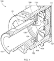
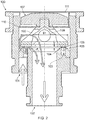
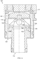
- FIGs 1 , 2 and 3 a valve assembly 100 according to a first exemplary embodiment not being part of the present invention is shown, Figure 1 being an isometric cross-sectional view and Figures 2 and 3 being orthogonal cross-sectional views. Figures 1 and 3 show the valve assembly in its closed position where Figure 2 shows the valve assembly in its open position.
- the diameter of the valve assembly 100 of the illustrated example is about 16mm, but other examples may be larger or smaller.
- Valve assembly 100 comprises a first fluid port 101 and a second fluid port 102.
- the first fluid port 101 is the fluid inlet and the second fluid port 102 is the fluid outlet.
- the first fluid port could be the fluid outlet and the second fluid port could be the fluid inlet.
- the direction of fluid flow is shown by the arrows in Figure 2 .
- Valve assembly 100 further comprises a valve seat 103 comprising an inner valve seat 104 and an outer valve seat 105 in a concentric arrangement, the inner valve seat 104 being arranged within the outer valve seat 105, and a valve seal 106.
- the assembly further comprises a moveable plunger 107 comprising an upper magnetic portion and a body 108 having an opening 109.
- a biasing means, preferably in the form of a spring 110 can also be provided, as can a non-moveable insulating membrane 111 for preventing fluid from combing into contact with a solenoid (not shown in Figure 1 ) of the valve assembly 100.
- the moveable plunger 107 is moveable between a closed position and an open position to vary a flow restriction at the valve seat, and is preferably arranged to simultaneously seal the inner valve seat 104 and the outer valve seat 105.
- a largest diameter D1 of the moveable plunger 107 can be around 10.2mm and a radial distance d1 between the inner valve seat 104 and the outer valve seat 105 may be 0.9mm.
- the overall stroke length of the moveable plunger 107 may be about 0.2mm.
- a first fluid pathway F 1 is arranged between the first fluid port 101 and the second fluid port 102, passing via the inner valve seat 104 (i.e. between the inner valve seat 104 and the valve seal 106) when the movable plunger 107 is in the open position.
- a second fluid pathway F 2 is arranged between the first fluid port 101 and the second fluid port, 102 passing via the outer valve seat 105 (i.e. between the outer valve seat 105 and the valve seal 106), when the movable plunger 107 is in the open position.
- a fluid flow path through the body 108 of the moveable plunger 107 comprising an opening 109 is configured to form part of the second fluid pathway F 2 .
- the cross-sectional area of the flow path through the moveable plunger 107 i.e. the minimum cross-sectional area, orthogonal to the flow direction, through which the fluid flow has to flow on the flow path through the moveable plunger 107, is at least approximately 50 times the cross-sectional area of the gap between the plunger and the outer valve seat 105 when the movable plunger 107 is in the open position. However, in other embodiments, this proportion may be as low as half of the cross-sectional area of the gap between the plunger and the outer valve seat 105.
- the flow path through the moveable plunger 107 is on the second fluid pathway F 2 of which the opening 109 forms a part.
- the depth G of the gap (or linear distance) between the plunger and the outer valve seat 105 of the second fluid pathway, of which the opening 109 forms a flow path is substantially equal to the depth G of the gap (or linear distance) between the plunger and the inner valve seat 104 of the first fluid pathway, of which the opening 109 does not form a flow path.
- the moveable plunger 107 seals the inner and outer valve seats 104, 105 across a single plane.
- fluid enters the valve assembly 100 through the first fluid port 101 and is able to flow via two paths.
- the first fluid pathway F 1 directly connects the first fluid port 101 and the second fluid port 102
- the second fluid pathway F 2 of which a fluid flow path or opening 108 through the body 109 of the moveable plunger 107 forms a part, also connects the first fluid port 101 and the second fluid port 102.
- the first fluid pathway and the second fluid pathway are, in preferred embodiments, the only fluid pathways between the first fluid port 101 and the second fluid port 102 when the movable plunger is in the open position.
- valve seal 106 is a seal made of a compliant material such as rubber, although any suitable sealant material can be used, be it of a compliant nature or not.
- an upper portion of the moveable plunger 107 is made of a magnetic material.
- the solenoid when an electric current is applied through the solenoid, the solenoid is energised and the magnetic field that is created as a result controls the movement of the magnetic moveable plunger 107 that opens and closes the valve, thus allowing or preventing fluid from flowing through the valve.
- the plunger When the solenoid is energised, the plunger may overcome the force of a spring 110 that holds the plunger in a normally closed position and be accelerated away from the valve seat 103.
- valve assembly may be a normally open valve assembly and so energisation of the solenoid causes the plunger to overcome the force of the spring that holds the plunger in a normally open position, such that it is accelerated towards the valve seat.
- the spring 110 is a flat spring, although other biasing means may be employed to provide the function of the spring described above.
- a non-moveable insulating membrane 111 is preferably provided above the moveable plunger 107, as shown in Figures 1 , 2 and 3 .
- the non-moveable insulating membrane 111 acts to isolate a portion of the moveable plunger 107 from the flow path through the body of the moveable plunger 107, in particular to prevent fluid from coming into contact with a solenoid (not shown in Figures 1 , 2 and 3 ) of the valve assembly 100.
- valve assembly 200 according to a second exemplary embodiment not being part of the present invention is shown, Figure 6 being an isometric cross-sectional view and Figures 5 and 6 being orthogonal cross-sectional views.
- Figures 4 and 6 show the valve assembly in its closed position;
- Figure 5 shows the valve assembly in its open position.
- the diameter of the valve assembly 200 is, in preferred examples, about 16mm.
- Valve assembly 200 comprises a first fluid port 201a, a second fluid port 202 and a third fluid port 201b.
- the first fluid port 201a and the third fluid port 201b are the fluid inlets and the second fluid port 202 is the fluid outlet.
- the first fluid port and the third fluid port could be fluid outlets and the second fluid port could be a fluid inlet.
- the direction of fluid flow is shown by the arrows in Figure 5 . It can be seen from Figure 7 that although there are three fluid ports in the second embodiment of the present invention, there are only two fluid pathways, and these will be described in further detail below.
- Valve assembly 200 further comprises a valve seat 203 comprising an inner valve seat 204 and an outer valve seat 205 in a concentric arrangement, the inner valve seat 204 being arranged within the outer valve seat 205 and a valve seal 206.
- the assembly further comprises a moveable plunger 207 comprising an upper magnetic portion and a body 208 having an opening 209.
- a biasing means, preferably in the form of a spring 210 can also be provided, as can a moveable diaphragm 211.
- the moveable plunger 207 is moveable between a closed position and an open position to vary a flow restriction at the valve seat, and is preferably arranged to simultaneously seal the inner valve seat 104 and the outer valve seat 105. Referring to Figure 5 , it can be seen that a largest diameter D2 of the moveable plunger 207 can be around 10.2mm and a radial distance d2 between the inner valve seat 104 and the outer valve seat 205 can be around 0.8mm.
- the stroke length of the moveable plunger 207 is, in preferred embodiments, about 0.2mm.
- a first fluid pathway F 1 is arranged between the first or third fluid ports 201a, 201b and the second fluid port 202, passing via the inner valve seat 204, (i.e. between in inner valve seat 204 and the valve seal 206) when the movable plunger 207 is in the open position.
- a second fluid pathway F 2 is arranged between the first or third fluid ports 201a, 201b and the second fluid port 202 passing via the outer valve seat 205 (i.e. between the outer valve seat 205 and the valve seal 206), when the movable plunger 207 is in the open position.
- a fluid flow path through the body 208 of the moveable plunger 207 comprising an opening 209 is configured to form part of the first fluid pathway F 1 .
- the cross-sectional area of the flow path through the moveable plunger 207 i.e. the minimum cross-sectional area, orthogonal to the flow direction, through which the fluid flow has to flow on the flow path through the moveable plunger 207, is at least approximately 50 times the cross-sectional area of the gap between the plunger and the inner valve seat 204 when the movable plunger 207 is in the open position. However, in other embodiments, this proportion may be as low as half of the cross-sectional area of the gap between the plunger and the inner valve seat 204.
- the flow path through the moveable plunger 207 is on the first fluid pathway F 1 of which the opening 109 forms a part.
- the depth G (or linear distance) of the gap between the plunger and the inner valve seat 204 of the second fluid pathway of which the opening 209 forms a flow path is substantially equal to the depth G (or linear distance) of the gap between the plunger and the outer valve seat 205 of the first fluid pathway of which the opening 209 does not form a flow path.
- the moveable plunger 207 seals the inner and outer valve seats 204, 205 across a single plane.
- the second fluid pathway F 2 directly connects the first and third fluid ports 201a, 201b and the second fluid port 202, and the first fluid pathway F 1 , of which a fluid flow path or opening 208 through the body 209 of the moveable plunger 207 forms a part, also connects the first and third fluid ports 2011, 201b and the second fluid port 202.
- the first fluid pathway and the second fluid pathway in preferred embodiments, are the only fluid pathways between the first and third fluid ports 201a, 201b and the second fluid port 202 when the movable plunger is in the open position.
- valve seal 206 is a seal made of a compliant material such as rubber, although any suitable sealant material can be used, be it of a compliant nature or not.
- an upper portion of the moveable plunger 207 is made of a magnetic material.
- the solenoid when an electric current is applied through the solenoid, the solenoid is energised it and the magnetic field that is created as a result controls the movement of the magnetic moveable plunger 107 that opens and closes the valve, thus allowing or preventing fluid from flowing through the valve.
- the plunger When the solenoid is energised, the plunger may overcome the force of a spring 210 that holds the plunger in a normally closed position and be accelerated away from the valve seat 203.
- valve assembly may be a normally open valve assembly and so energisation of the solenoid causes the plunger to overcome the force of the spring that holds the plunger in a normally open position such that it is accelerated towards the valve seat.
- the spring 210 is a flat spring, although other biasing means may be employed to provide the function of the spring described above.
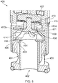
- FIG. 7 a schematic (upright) sectional view of a valve assembly 300 in its closed position according to a third embodiment according to the present invention is shown.
- Valve assembly 300 comprises a first fluid port 301 and a second fluid port 302.
- the first fluid port 301 is the fluid inlet and the second fluid port 302 is the fluid outlet.
- the first fluid port could be the fluid outlet and the second fluid port could be the fluid inlet.
- Valve assembly 300 further comprises a valve seat 303 comprising inner valve seat 304 and outer valve seat 305 in a concentric arrangement, the inner valve seat 304 being arranged within the outer valve seat 305 and a valve seal 306.
- the assembly further comprises a moveable plunger 307 comprising an upper magnetic portion and a body 308 having an opening 309 (not visible in the schematic view of Figure 7 ).
- a biasing means, preferably in the form of a spring 310 can also be provided, as can a moveable diaphragm 311, a pressure equalising fluid pathway 312, an upper shim 313a and a lower shim 313b.
- the pressure equalising fluid pathway 312 is a pressure compensation means for ensuring that the fluid inlet and a portion of the moveable plunger that is not in a direct flow path between the first and second fluid ports are under substantially the same pressure when the moveable plunger is in the closed position. In other words, fluid flow between the first and second fluid ports is prevented in this portion of the moveable plunger.
- the pressure equalising fluid pathway 312 extends from the second fluid port 302, the fluid inlet in this case, to a portion of the moveable plunger that is not in a direct flow path between the first fluid port 301 and the second fluid port 302.
- the pressure equalising fluid pathway can extend from the first fluid port to a portion of the moveable plunger that is not in a direct flow path between the first fluid port and the second fluid port.
- the upper shim 313a is for varying the area of the moveable diaphragm 311 that can be biased by pressure from the first fluid port 301. Pressure within the valve chamber 314 can cause the moveable diaphragm 311 to be biased outwardly from the valve chamber 314. Varying the inner diameter of the opening in the upper shim 313a can therefore vary the amount of biasing of the moveable diaphragm 311 outwardly from the valve chamber 314.
- the lower shim 313b is for varying the area of the moveable diaphragm 311 that can be biased by pressure from the second fluid port 302. Pressure within the pressure compensating chamber 315 can cause the moveable diaphragm 311 to be biased outwardly from the pressure compensating chamber 315. Varying the inner diameter of the opening in the upper shim 313b can therefore vary the amount of biasing of the moveable diaphragm 311 outwardly from the pressure compensating chamber 315. Thus, different diameters of the upper shim 313a and lower shim 313b can vary the amount of pressure exerted by the valve chamber 314 and the pressure compensating chamber 315 upon the moveable diaphragm, respectively.
- valve seal 306 The upwards pressure on the valve seal 306 is compensated by the downwards pressure on the moveable plunger 307 from the fluid inlet via the pressure equalising fluid pathway 312. This advantageously provides a flexible approach to varying the pressure that is exerted on the portion of the moveable plunger 307 that is not in a direct flow path between the first and second fluid ports 301, 302.
- FIG 8 a schematic (upright) view of valve assembly 400 in its closed position according to a fourth embodiment according to the present invention is shown.
- Valve assembly 400 comprises a first fluid port 401 and a second fluid port 402.
- the first fluid port 401 is the fluid inlet and the second fluid port 402 is the fluid outlet.
- the first fluid port could be the fluid outlet and the second fluid port could be the fluid inlet.
- Valve assembly 400 further comprises a valve seat 403 comprising inner valve seat 404 and outer valve seat 305 in a concentric arrangement, the inner valve seat 404 being arranged within the outer valve seat 405 and a valve seal 406.
- the assembly further comprises a moveable plunger 407 comprising an upper magnetic portion and a body 408 having an opening 409.
- a biasing means preferably in the form of a spring 410 can also be provided, as can a moveable diaphragm 411, a pressure equalising fluid pathway (not visible in the schematic view of Figure 8 ), an upper shim 413a and a lower shim 413b.
- the pressure equalising fluid pathway is a pressure compensation means for ensuring that the fluid inlet and a portion of the moveable plunger that is not in a direct flow path between the first and second fluid ports are under substantially the same pressure when the moveable plunger is in the closed position. It extends from the first fluid port 401, the fluid inlet in this case, to a portion of the moveable plunger that is not in a direct flow path between the first fluid port 401 and the second fluid port 402.
- the upper shim 413a is for varying the area of the moveable diaphragm 411 that can be biased by pressure from the first fluid port 301. Pressure within the valve chamber 414 can cause the moveable diaphragm 411 to be biased outwardly from the valve chamber 414. Varying the inner diameter of the opening in the upper shim 413a can therefore vary the amount of biasing of the moveable diaphragm 411 outwardly from the valve chamber 414.
- the lower shim 413b is for varying the area of the moveable diaphragm 411 that can be biased by pressure from the second fluid port 402. Pressure within the pressure compensating chamber 315 can cause the moveable diaphragm 411 to be biased outwardly from the pressure compensating chamber 415. Varying the inner diameter of the opening in the upper shim 413b can therefore vary the amount of biasing of the moveable diaphragm 411 outwardly from the pressure compensating chamber 415.
- different diameters of the upper shim 413a and lower shim 413b can vary the amount of pressure exerted by the valve chamber 414 and the pressure compensating chamber 415 upon the moveable diaphragm, respectively.
- the upwards pressure on the valve seal 406 is compensated by the downwards pressure on the moveable plunger 407 from the fluid inlet via the pressure equalising fluid pathway. This advantageously provides a flexible approach to varying the pressure that is exerted on the portion of the moveable plunger 407 that is not in a direct flow path between the first and second fluid ports 401, 402.
Landscapes
- Engineering & Computer Science (AREA)
- General Engineering & Computer Science (AREA)
- Mechanical Engineering (AREA)
- Physics & Mathematics (AREA)
- Electromagnetism (AREA)
- Magnetically Actuated Valves (AREA)
- Lift Valve (AREA)
Description
- The present invention relates to a valve assembly and in particular to a microfluidic valve assembly having an improved flow characteristic.
- Fluid control valves are used in a wide variety of applications to control the flow of a fluid. The fluid being controlled may comprise a gas, a liquid, or a combination thereof. In some situations, the fluid may also include suspended particulates. While fluid control valves vary widely in the specific configuration used to open and close a fluid communication path through the valve, one specific type of valve actuation is performed using a solenoid.
- In solenoid-actuated valves, an electric current passes through an electromagnetic coil, with the coil typically formed around a magnetic core. The coil generally comprises a wire that is wrapped around a bobbin numerous times resulting in a plurality of so-called turns. The energized solenoid generates a magnetic field. The strength of the magnetic field is proportional to the number of turns as well as the electrical current provided to the wire.
- As is well-known in the art, in order to increase the magnetic field provided by a solenoid, the number of turns can be increased and/or the current provided to the wire can be increased. The magnetic field typically operates on a movable armature connected to a plunger which is configured to engage a valve seat, which surrounds an inlet and/or outlet through which fluid may pass, to vary a flow restriction created by the valve seat and a sealing portion of the plunger.
- Typically, the valve also includes a spring or other biasing member that generates a biasing force in opposition to the magnetic field. Therefore, in the absence of a magnetic field generated by the solenoid, the valve member is moved into a normally open or a normally closed position. In an open position, the plunger is in a position away from the valve seat, allowing fluid to pass through the inlet and/or outlet. In a closed position, the sealing portion of the plunger abuts the valve seat so as to close the inlet and/or outlet, preventing fluid from passing through the inlet and/or outlet.
- When the valve assembly is required to be small and light, it is important to control the flow characteristics of the valve, for example, to achieve a sufficiently high flow rate. However, there are challenges in achieving this when increases in the plunger stroke length and cross-sectional area of the valve seat may be restricted in a small valve assembly. Particularly in small valves, the lack of space available within the body of the valve may force the design of complicated and/or additional valve parts and create tortuous flow paths with many direction changes and flow restrictions, etc. The consequences of this are an increase of the cost of the valve, a decrease of the manufacturability of the valve and rather unpredictable flow capabilities.
- There is therefore a need for improvements in valve assemblies.
-
US6619322 B1 discloses a fast-acting valve that includes an annular valve seat that defines an annular valve orifice between the edges of the annular valve seat, an annular valve plug sized to cover the valve orifice when the valve is closed, and a valve-plug holder for moving the annular valve plug on and off the annular valve seat. -
US2011/175004 A1 discloses an electromagnetically actuated valve with a valve body which is assigned to a valve seat, the valve being mechanically pre-stressed in a first direction toward a first switching position and can be adjusted by means of a magnetic actuator in a second, opposite direction into a second switching position. -
DE10319920 A1 discloses a valve for controlling a fluid, in particular one with electromagnetic actuation, comprising a valve closing element which controls a fluid flow from an inflow side to an outflow side and which interacts with a valve seat designed as a flat seat. -
US2013/205986 A1 discloses an annular valve comprising an annular valve member and inner and outer annular valve seats. Inner and outer sealing ridges are formed either on the annular valve member or on the valve seats. -
US2018/128382 A1 discloses a valve with a valve seat comprising an inner path providing a first flow channel adapted to be in contact with a first chamber of the valve, the valve seat comprising at least one outer path also adapted to be in contact with the first chamber, the valve seat further comprising an area facing a sealing of the valve, said area adapted to be in connection with a second chamber, said area having an inner sealing edge and an outer sealing edge, and wherein said valve seat is adapted to allow for a flow between said first chamber and said second chamber when the valve is in an open position, wherein said flow in said inner path and said at least one outer path flow through said area being in contact with the second chamber via the inner sealing edge and the outer sealing edge, respectively. -
US2013/112904 A1 discloses a magnetic core for a solenoid valve. The magnetic core includes a first part defining a cavity. The first part is formed from a first material having a first magnetic performance. The magnetic core also includes a second part positioned at least partially within the cavity. The second part is formed from a second material having a second magnetic performance that is higher than the first magnetic performance. - The present inventors have recognised that improved valve assemblies having better control over the volume of fluid that passes between the inlet and the outlet when the plunger is in an open position are required. In particular, they have recognised that by introducing a fluid flow path in a moveable plunger of a valve assembly, a dual fluid pathway can be provided, in that fluid may flow between two fluid ports of the valve assembly via two flow paths, i.e. a first flow path directly between the two fluid ports and a second flow path through the plunger. The result is that a higher flow rate may be achieved for a given valve assembly size and the proportion of fluid passing through each flow path may be optimised for a particular application.
- Thus, according to a first aspect of the invention, there is provided a valve assembly, comprising: a first fluid port; a second fluid port; a valve seat comprising an inner valve seat and an outer valve seat, the inner valve seat being arranged within the outer valve seat; a moveable plunger, having a body and being moveable between a closed position and an open position to vary a flow restriction at the valve seat, and arranged to simultaneously seal the inner valve seat and the outer valve seat when in the closed position; a first fluid pathway between the first fluid port and the second fluid port passing via the inner valve seat when the movable plunger is in the open position; a second fluid pathway between the first fluid port and the second fluid port passing via the outer valve seat when the movable plunger is in the open position; at least one fluid flow path through the body of the moveable plunger comprising an opening configured to form part of the first fluid pathway or the second fluid pathway, and wherein the cross-sectional area of the flow path through the moveable plunger is at least half of the cross-sectional area of the gap between the plunger and the respective inner or outer valve seat of the first or second fluid pathway of which the opening forms a flow path when the movable plunger is in the open position, a moveable diaphragm for separating a portion of the moveable plunger from the flow path through the body of the moveable plunger; and pressure compensation means configured such that one of the first fluid port and the second fluid port, and a portion of the moveable plunger that is not in a direct flow path between the first and second fluid ports, are under substantially the same pressure when the moveable plunger is in the closed position.
- The at least one fluid flow path through the body of the moveable plunger allows for improved flow characteristics of the valve assembly in terms of increased flow for a given plunger stroke length and a given cross-sectional area of the valve seat, less flow resistance and less turbulence. This is particularly advantageous for small valves, for example, having dimensions of the order 10-2m (e.g. around 10mm) and cross-sectional areas of the valve seat of the order 10-5 m2, for which the plunger stroke length and cross-sectional area of the valve seat may typically be of the magnitude 10-3m.
- Alternatively, for a given flow requirement, the at least one fluid flow path through the body of the moveable plunger advantageously permits a smaller plunger stroke length for a given cross-sectional area of the valve seat.
- Moreover, the at least one fluid flow path through the body of the moveable plunger allows for decreased pressure within the valve assembly or increased back pressure sensitivity for the same flow rate.
- The metric of the cross-sectional area of the flow path through the moveable plunger being at least half of the cross-sectional area of the gap between the plunger and the respective inner or outer valve seat of the first or second fluid pathway of which the opening forms a flow path when the movable plunger is in the open position may be considered a minimum requirement in order to show significant improvements in flow characteristic of the valve assembly compared to prior art arrangements.
- It will be appreciated that the first fluid port and the second fluid port could be the fluid inlet and the fluid outlet, respectively, or vice versa. In other words, the presently claimed invention is not restricted by the direction of fluid flow within the valve assembly.
- The advantage of having only the first fluid port and the second fluid port in the valve assembly, i.e. having only one inlet and only one outlet, is that the design of the valve assembly may be simple and compact. However, in addition to the first fluid port and the second fluid port, the valve assembly may have other fluid ports, and so the valve assembly may have multiple inlets and/or outlets in some examples. The location of the inlet(s) and outlet(s) may be various depending on the specific application of the valve assembly. The valve may be a proportional valve or a switching (i.e. ON/OFF valve). The valve may be a direct valve or a pressure compensated valve.
- In one example, when the moveable plunger is in the open position, the first fluid pathway directly connects the first fluid port and the second fluid port, and the second fluid pathway, of which the fluid flow path through the body of the moveable plunger forms a part, also connects the first fluid port and the second fluid port. In this example, when the moveable plunger is in the closed position, fluid from one of the first and second fluid ports reaches the outer edge of the inner valve seat where it is prevented from passing through by the seal created by the moveable plunger, and fluid from the other of the first and second fluid ports passes through the fluid flow path through the body of the moveable plunger and reaches the outer edge of the outer valve seat where it is prevented from passing through by the seal created by the moveable plunger.
- In another example, when the moveable plunger is in the open position, the second fluid pathway directly connects the first fluid port and the second fluid port, and the first fluid pathway, of which the fluid flow path through the body of the moveable plunger forms a part, also connects the first fluid port and the second fluid port. In this example, when the moveable plunger is in the closed position, fluid from one of the first and second fluid ports reaches the outer edge of the outer valve seat where it is prevented from passing through by the seal created by the moveable plunger, and fluid from the other of the first and second fluid ports passes through the fluid flow path through the body of the moveable plunger and reaches the outer edge of the inner valve seat where it is prevented from passing through by the seal created by the moveable plunger.
- It may be preferable that the first fluid pathway and the second fluid pathway are the only fluid pathways between the first fluid port and the second fluid port when the movable plunger is in the open position. For example, the fluid flow as described in the two above examples may represent the only fluid pathways in the valve assembly. Thus, fluid flow is limited between said two fluid pathways and so it is easier to control. Particularly in small valves of the order of magnitude described above, having a limited number of fluid pathways allows for simplicity of the valve design, lower manufacturing costs and better manufacturability of the valves. Further, particularly in small valves of the order of magnitude described above, having a limited number of fluid pathways allows for simplicity of the fluid pathway design and better efficiency of the fluid pathway due to less direction changes of the fluid.
- In some preferable arrangements, the cross-sectional area of the flow path through the opening in the moveable plunger may be at least 0.6 or 60%, 0.7 or 70%, 0.8 or 80%, 0.9 or 90%, equal to, or 100% or greater, of the cross-sectional area of the gap between the plunger and the respective inner or outer valve seat of the first or second fluid pathway of which the opening forms a flow path when the movable plunger is in the open position.
- In other preferable arrangements, the cross-sectional area of the flow path through the opening in the moveable plunger may be at least two times, preferably at least 10 times, more preferably at least 50 times, the cross-sectional area of the gap between the plunger and the respective inner or outer valve seat of the first or second fluid pathway of which the opening forms a flow path when the movable plunger is in the open position. This generally defines a minimum cross sectional area of an opening through the moveable plunger, such that this defines the maximum restriction on the flow through the opening in the moveable plunger.
- The greater the cross-sectional area of the opening in the moveable plunger for a fixed cross-sectional area of the gap between the plunger and the respective inner or outer valve seat of the first or second fluid pathway of which the opening forms a flow path, the higher the flow rate of fluid between the first and second fluid ports. In some particularly preferable examples, the cross-sectional area of the opening in the moveable plunger may be much higher than half of the cross-sectional area of the gap between the plunger and the respective inner or outer valve seat of the first or second fluid pathway of which the opening forms a flow path when the movable plunger is in the open position. This has the advantage of delivering a very high fluid output for a given plunger stroke length. It is preferable, for optimal valve control, that the greatest flow restriction in the flow path is represented by the maximum available opening at the valve seat, since this is that opening that is controlled to operate the valve as a flow restriction. Configuring the valve in this way provides efficient flow paths through the remaining components of the valve.
- The fixed stroke of the moveable plunger may be between 0.05mm and 1.0mm. Preferably, the fixed stroke of the moveable plunger may be between 0.1mm and 0.3mm. More preferably, the fixed stroke of the moveable plunger may be 0.2mm. Additionally or alternatively, the fixed stroke length may be less than a quarter of the diameter of the opening through the body of the moveable plunger.
- In some examples, when the movable plunger is in the open position, the cross-sectional area, or the linear distance from valve seat to plunger, of the gap between the plunger and the respective inner or outer valve seat of the first or second fluid pathway of which the opening forms a flow path may be substantially equal to the cross-sectional area, or the linear distance from valve seat to plunger, of the gap between the plunger and the respective inner or outer valve seat of the first or second fluid pathway of which the opening does not form a flow path. This is typically the case when the moveable plunger seals the inner and outer valve seats across a single plane.
- Alternatively, the cross-sectional area of the gap between the plunger and the respective inner or outer valve seat of the first or second fluid pathway of which the opening forms a flow path may be greater than or less than the cross-sectional area of the gap between the plunger and the respective inner or outer valve seat of the first or second fluid pathway of which the opening does not form a flow path. This may occur when the moveable plunger does not seal the inner and outer valve seats across a single plane. The valve assembly comprises a moveable diaphragm for separating a portion of the moveable plunger from the opening through the body of the moveable plunger. By "separating", it is meant that the moveable plunger is positioned such that there is no direct fluid pathway from said portion of the moveable plunger and the opening through the body of the moveable plunger. The valve assembly further comprises pressure compensation means for ensuring that the fluid inlet and a portion of the moveable plunger that is not in a direct flow path between the first and second fluid ports are under substantially the same pressure when the moveable plunger is in the closed position. Advantageously, this means that the moveable plunger may be kept from moving to its open position unintentionally.
- The pressure compensation means may be a pressure equalising fluid pathway from the first fluid port or the second fluid port to a portion of the moveable plunger that is not in a direct flow path between the first fluid port and the second fluid port. The pressure equalising pathway usually extends from the fluid port that is a fluid inlet to a portion of the moveable plunger that is not in a direct flow path between the both fluid inlet and the fluid outlet or is at least not in a direct flow path between them. This is because the fluid inlet is usually at a higher pressure than the fluid outlet.
- The valve assembly may further comprise a shim for varying the area of the moveable diaphragm that can be biased by pressure from the first fluid port or the second fluid port. This advantageously provides a flexible approach to varying the pressure that is exerted on the portion of the moveable plunger that is not in a direct flow path between the first and second fluid ports.
- Preferably, the valve assembly may further comprise actuating means for actuating the moveable plunger, in use, between the first position and the second position. The actuating means may comprises a solenoid that actuates the moveable plunger upon the application of a current through the solenoid. In this case, the moveable plunger may comprise or consist of a magnetic material.
- In such electrically actuated solenoid valve assemblies, an electric current may be applied through the solenoid which energises it and the magnetic field that is created as a result controls the movement of the magnetic plunger that opens and closes the valve, thus allowing or preventing fluid from flowing through the valve. When the solenoid is energised, the plunger may overcome the force of a spring that holds the plunger in a normally open or normally closed position and be accelerated towards or away from a valve seat. A hold voltage may be applied to the solenoid in order to advance the movement of the plunger towards or away from the valve seat and/or to retain the valve in a closed or open position. Sometimes, a braking voltage may also be applied in order to brake the movement of the plunger so as to lessen its impact upon the valve seat.
- By way of comparison to these solenoid actuated valve assemblies, valve assemblies employing other actuator technology may display the following disadvantages. A voice coil may be more expensive, create less force and have a larger size. A shape-memory allow (SMA) may have a slower response time and have a larger size, in particular height-wise.
- In preferable examples of the present invention, the inner valve seat and the outer valve seat are arranged concentrically. A concentric design provides the advantage of being compact and optimising the use of space within the valve assembly, which may be limited, for example, in a small valve assembly such as a microfluidic valve assembly. According to a second aspect of the invention, there is provided a valve system, comprising at least two valve assemblies of any preceding claim, wherein the distance between adjacent valve assemblies is less than 50mm, preferably less than 40mm, more preferably less than 20mm.
- The advantages described above in relation to a single valve assembly also equally apply to the valve system.
- Embodiments of the present invention will now be described, by non-limiting example only, with reference to the accompanying drawings, in which:
-
Figure 1 shows an isometric cross-sectional view of a valve assembly in accordance with a first exemplary embodiment not being part of the present invention; -
Figure 2 shows an orthogonal cross-sectional view of a valve assembly in its open position in accordance with the first exemplary embodiment not being part of the present invention; -
Figure 3 shows an orthogonal cross-sectional view of a valve assembly in its closed position in accordance with the first exemplary embodiment not being part of the present invention; -
Figure 4 shows an isometric cross-sectional view of a valve assembly in accordance with a second exemplary embodiment not being part of the present invention; -
Figure 5 shows an orthogonal cross-sectional view of a valve assembly in its open position in accordance with the second exemplary embodiment not being part of the present invention; -
Figure 6 shows an orthogonal cross-sectional view of a valve assembly in its closed position in accordance with the second exemplary embodiment not being part of the present invention; -
Figure 7 shows a schematic view of a valve assembly in accordance with a third embodiment according to the present invention; and -
Figure 8 shows a schematic view of a valve assembly in accordance with a fourth embodiment according to the present invention. - The following detailed description and figures provide examples of how the present invention can be implemented and should not be seen as limiting examples, rather illustrations of how the various features of the valve assembly disclosed herein can be combined, although other optional combinations will be evident upon reading the following description in light of the figures.
- In
Figures 1 ,2 and3 , avalve assembly 100 according to a first exemplary embodiment not being part of the present invention is shown,Figure 1 being an isometric cross-sectional view andFigures 2 and3 being orthogonal cross-sectional views.Figures 1 and3 show the valve assembly in its closed position whereFigure 2 shows the valve assembly in its open position. The diameter of thevalve assembly 100 of the illustrated example is about 16mm, but other examples may be larger or smaller. -
Valve assembly 100 comprises a firstfluid port 101 and a secondfluid port 102. In this embodiment, the firstfluid port 101 is the fluid inlet and the secondfluid port 102 is the fluid outlet. However, it will be appreciated that in other embodiments, the first fluid port could be the fluid outlet and the second fluid port could be the fluid inlet. The direction of fluid flow is shown by the arrows inFigure 2 . -
Valve assembly 100 further comprises avalve seat 103 comprising aninner valve seat 104 and anouter valve seat 105 in a concentric arrangement, theinner valve seat 104 being arranged within theouter valve seat 105, and avalve seal 106. The assembly further comprises amoveable plunger 107 comprising an upper magnetic portion and abody 108 having anopening 109. A biasing means, preferably in the form of aspring 110 can also be provided, as can a non-moveable insulatingmembrane 111 for preventing fluid from combing into contact with a solenoid (not shown inFigure 1 ) of thevalve assembly 100. - The
moveable plunger 107 is moveable between a closed position and an open position to vary a flow restriction at the valve seat, and is preferably arranged to simultaneously seal theinner valve seat 104 and theouter valve seat 105. InFigure 2 , it can be seen that, in certain preferred embodiments a largest diameter D1 of themoveable plunger 107 can be around 10.2mm and a radial distance d1 between theinner valve seat 104 and theouter valve seat 105 may be 0.9mm. The overall stroke length of themoveable plunger 107 may be about 0.2mm. - A first fluid pathway F1 is arranged between the first
fluid port 101 and the secondfluid port 102, passing via the inner valve seat 104 (i.e. between theinner valve seat 104 and the valve seal 106) when themovable plunger 107 is in the open position. A second fluid pathway F2 is arranged between the firstfluid port 101 and the second fluid port, 102 passing via the outer valve seat 105 (i.e. between theouter valve seat 105 and the valve seal 106), when themovable plunger 107 is in the open position. Further, a fluid flow path through thebody 108 of themoveable plunger 107 comprising anopening 109 is configured to form part of the second fluid pathway F2. The cross-sectional area of the flow path through themoveable plunger 107, i.e. the minimum cross-sectional area, orthogonal to the flow direction, through which the fluid flow has to flow on the flow path through themoveable plunger 107, is at least approximately 50 times the cross-sectional area of the gap between the plunger and theouter valve seat 105 when themovable plunger 107 is in the open position. However, in other embodiments, this proportion may be as low as half of the cross-sectional area of the gap between the plunger and theouter valve seat 105. The flow path through themoveable plunger 107 is on the second fluid pathway F2 of which theopening 109 forms a part. - As shown in
Figure 2 , the depth G of the gap (or linear distance) between the plunger and theouter valve seat 105 of the second fluid pathway, of which theopening 109 forms a flow path, is substantially equal to the depth G of the gap (or linear distance) between the plunger and theinner valve seat 104 of the first fluid pathway, of which theopening 109 does not form a flow path. In other words, themoveable plunger 107 seals the inner andouter valve seats - In the open position shown in
Figure 2 , fluid enters thevalve assembly 100 through the firstfluid port 101 and is able to flow via two paths. The first fluid pathway F1 directly connects the firstfluid port 101 and the secondfluid port 102, and the second fluid pathway F2, of which a fluid flow path or opening 108 through thebody 109 of themoveable plunger 107 forms a part, also connects the firstfluid port 101 and the secondfluid port 102. The first fluid pathway and the second fluid pathway are, in preferred embodiments, the only fluid pathways between the firstfluid port 101 and the secondfluid port 102 when the movable plunger is in the open position. - In this embodiment, when the
moveable plunger 107 is in the closed position, as shown inFigures 1 and3 , fluid from the secondfluid port 102 reaches the outer edge of theinner valve seat 104 where it is prevented from passing through by theseal 106 created by themoveable plunger 107. Fluid from the firstfluid port 101 can extend through the fluid flow path or opening 108 through thebody 109 of themoveable plunger 107 and can reach the outer edge of theouter valve seat 105, where it is prevented from passing through by theseal 106 created by themoveable plunger 107. In this embodiment, thevalve seal 106 is a seal made of a compliant material such as rubber, although any suitable sealant material can be used, be it of a compliant nature or not. - In the electrically actuated solenoid valve of
Figures 1 ,2 and3 , an upper portion of themoveable plunger 107 is made of a magnetic material. Thus, when an electric current is applied through the solenoid, the solenoid is energised and the magnetic field that is created as a result controls the movement of the magneticmoveable plunger 107 that opens and closes the valve, thus allowing or preventing fluid from flowing through the valve. When the solenoid is energised, the plunger may overcome the force of aspring 110 that holds the plunger in a normally closed position and be accelerated away from thevalve seat 103. It will be appreciated that in other embodiments, the valve assembly may be a normally open valve assembly and so energisation of the solenoid causes the plunger to overcome the force of the spring that holds the plunger in a normally open position, such that it is accelerated towards the valve seat. In this embodiment, thespring 110 is a flat spring, although other biasing means may be employed to provide the function of the spring described above. - A non-moveable insulating
membrane 111 is preferably provided above themoveable plunger 107, as shown inFigures 1 ,2 and3 . The non-moveable insulatingmembrane 111 acts to isolate a portion of themoveable plunger 107 from the flow path through the body of themoveable plunger 107, in particular to prevent fluid from coming into contact with a solenoid (not shown inFigures 1 ,2 and3 ) of thevalve assembly 100. - In
Figures 4 ,5 and6 , avalve assembly 200 according to a second exemplary embodiment not being part of the present invention is shown,Figure 6 being an isometric cross-sectional view andFigures 5 and6 being orthogonal cross-sectional views.Figures 4 and6 show the valve assembly in its closed position;Figure 5 shows the valve assembly in its open position. The diameter of thevalve assembly 200 is, in preferred examples, about 16mm. -
Valve assembly 200 comprises afirst fluid port 201a, a secondfluid port 202 and a thirdfluid port 201b. In this embodiment, thefirst fluid port 201a and the thirdfluid port 201b are the fluid inlets and the secondfluid port 202 is the fluid outlet. However, it will be appreciated that in other embodiments, the first fluid port and the third fluid port could be fluid outlets and the second fluid port could be a fluid inlet. The direction of fluid flow is shown by the arrows inFigure 5 . It can be seen fromFigure 7 that although there are three fluid ports in the second embodiment of the present invention, there are only two fluid pathways, and these will be described in further detail below. -
Valve assembly 200 further comprises avalve seat 203 comprising aninner valve seat 204 and anouter valve seat 205 in a concentric arrangement, theinner valve seat 204 being arranged within theouter valve seat 205 and avalve seal 206. The assembly further comprises amoveable plunger 207 comprising an upper magnetic portion and abody 208 having anopening 209. A biasing means, preferably in the form of aspring 210 can also be provided, as can a moveable diaphragm 211. - The
moveable plunger 207 is moveable between a closed position and an open position to vary a flow restriction at the valve seat, and is preferably arranged to simultaneously seal theinner valve seat 104 and theouter valve seat 105. Referring toFigure 5 , it can be seen that a largest diameter D2 of themoveable plunger 207 can be around 10.2mm and a radial distance d2 between theinner valve seat 104 and theouter valve seat 205 can be around 0.8mm. The stroke length of themoveable plunger 207 is, in preferred embodiments, about 0.2mm. - A first fluid pathway F1 is arranged between the first or
third fluid ports fluid port 202, passing via theinner valve seat 204, (i.e. between ininner valve seat 204 and the valve seal 206) when themovable plunger 207 is in the open position. A second fluid pathway F2 is arranged between the first orthird fluid ports fluid port 202 passing via the outer valve seat 205 (i.e. between theouter valve seat 205 and the valve seal 206), when themovable plunger 207 is in the open position. Further, a fluid flow path through thebody 208 of themoveable plunger 207 comprising anopening 209 is configured to form part of the first fluid pathway F1. The cross-sectional area of the flow path through themoveable plunger 207, i.e. the minimum cross-sectional area, orthogonal to the flow direction, through which the fluid flow has to flow on the flow path through themoveable plunger 207, is at least approximately 50 times the cross-sectional area of the gap between the plunger and theinner valve seat 204 when themovable plunger 207 is in the open position. However, in other embodiments, this proportion may be as low as half of the cross-sectional area of the gap between the plunger and theinner valve seat 204. The flow path through themoveable plunger 207 is on the first fluid pathway F1 of which theopening 109 forms a part. - As shown in
Figure 5 , the depth G (or linear distance) of the gap between the plunger and theinner valve seat 204 of the second fluid pathway of which theopening 209 forms a flow path is substantially equal to the depth G (or linear distance) of the gap between the plunger and theouter valve seat 205 of the first fluid pathway of which theopening 209 does not form a flow path. In other words, themoveable plunger 207 seals the inner andouter valve seats - In the open position shown in
Figure 5 , fluid enters thevalve assembly 200 through thefirst fluid port 201a and the thirdfluid port 201b and is able to flow via two paths. The second fluid pathway F2 directly connects the first andthird fluid ports fluid port 202, and the first fluid pathway F1, of which a fluid flow path or opening 208 through thebody 209 of themoveable plunger 207 forms a part, also connects the first andthird fluid ports 2011, 201b and the secondfluid port 202. The first fluid pathway and the second fluid pathway, in preferred embodiments, are the only fluid pathways between the first andthird fluid ports fluid port 202 when the movable plunger is in the open position. - In this embodiment, when the
moveable plunger 207 is in the closed position, as shown inFigures 4 and6 , fluid from the first andthird fluid ports body 209 of themoveable plunger 207 and reaches the outer edge of theinner valve seat 204 where it is prevented from passing through by theseal 206 created by themoveable plunger 207. Fluid from the secondfluid port 202 can reach the outer edge of theouter valve seat 205 where it is prevented from passing through by theseal 206 created by themoveable plunger 207. In this embodiment, thevalve seal 206 is a seal made of a compliant material such as rubber, although any suitable sealant material can be used, be it of a compliant nature or not. - In the electrically actuated solenoid valve of
Figures 4 ,5 and6 , an upper portion of themoveable plunger 207 is made of a magnetic material. Thus, when an electric current is applied through the solenoid, the solenoid is energised it and the magnetic field that is created as a result controls the movement of the magneticmoveable plunger 107 that opens and closes the valve, thus allowing or preventing fluid from flowing through the valve. When the solenoid is energised, the plunger may overcome the force of aspring 210 that holds the plunger in a normally closed position and be accelerated away from thevalve seat 203. It will be appreciated that in other embodiments, the valve assembly may be a normally open valve assembly and so energisation of the solenoid causes the plunger to overcome the force of the spring that holds the plunger in a normally open position such that it is accelerated towards the valve seat. In this embodiment, thespring 210 is a flat spring, although other biasing means may be employed to provide the function of the spring described above. - In
Figure 7 , a schematic (upright) sectional view of avalve assembly 300 in its closed position according to a third embodiment according to the present invention is shown. -
Valve assembly 300 comprises a firstfluid port 301 and a secondfluid port 302. In this embodiment, the firstfluid port 301 is the fluid inlet and the secondfluid port 302 is the fluid outlet. However, it will be appreciated that in other embodiments, the first fluid port could be the fluid outlet and the second fluid port could be the fluid inlet. -
Valve assembly 300 further comprises avalve seat 303 comprisinginner valve seat 304 andouter valve seat 305 in a concentric arrangement, theinner valve seat 304 being arranged within theouter valve seat 305 and avalve seal 306. The assembly further comprises amoveable plunger 307 comprising an upper magnetic portion and abody 308 having an opening 309 (not visible in the schematic view ofFigure 7 ). A biasing means, preferably in the form of aspring 310 can also be provided, as can amoveable diaphragm 311, a pressure equalisingfluid pathway 312, anupper shim 313a and alower shim 313b. - The pressure equalising
fluid pathway 312 is a pressure compensation means for ensuring that the fluid inlet and a portion of the moveable plunger that is not in a direct flow path between the first and second fluid ports are under substantially the same pressure when the moveable plunger is in the closed position. In other words, fluid flow between the first and second fluid ports is prevented in this portion of the moveable plunger. Advantageously, this means that the moveable plunger may be kept from moving to its open position unintentionally. - The pressure equalising
fluid pathway 312 extends from the secondfluid port 302, the fluid inlet in this case, to a portion of the moveable plunger that is not in a direct flow path between the firstfluid port 301 and the secondfluid port 302. In other embodiments, the pressure equalising fluid pathway can extend from the first fluid port to a portion of the moveable plunger that is not in a direct flow path between the first fluid port and the second fluid port. - The
upper shim 313a is for varying the area of themoveable diaphragm 311 that can be biased by pressure from the firstfluid port 301. Pressure within thevalve chamber 314 can cause themoveable diaphragm 311 to be biased outwardly from thevalve chamber 314. Varying the inner diameter of the opening in theupper shim 313a can therefore vary the amount of biasing of themoveable diaphragm 311 outwardly from thevalve chamber 314. - The
lower shim 313b is for varying the area of themoveable diaphragm 311 that can be biased by pressure from the secondfluid port 302. Pressure within thepressure compensating chamber 315 can cause themoveable diaphragm 311 to be biased outwardly from thepressure compensating chamber 315. Varying the inner diameter of the opening in theupper shim 313b can therefore vary the amount of biasing of themoveable diaphragm 311 outwardly from thepressure compensating chamber 315. Thus, different diameters of theupper shim 313a andlower shim 313b can vary the amount of pressure exerted by thevalve chamber 314 and thepressure compensating chamber 315 upon the moveable diaphragm, respectively. - The upwards pressure on the
valve seal 306 is compensated by the downwards pressure on themoveable plunger 307 from the fluid inlet via the pressure equalisingfluid pathway 312. This advantageously provides a flexible approach to varying the pressure that is exerted on the portion of themoveable plunger 307 that is not in a direct flow path between the first and secondfluid ports - In
Figure 8 , a schematic (upright) view ofvalve assembly 400 in its closed position according to a fourth embodiment according to the present invention is shown. -
Valve assembly 400 comprises a firstfluid port 401 and a secondfluid port 402. In this embodiment, the firstfluid port 401 is the fluid inlet and the secondfluid port 402 is the fluid outlet. However, it will be appreciated that in other embodiments, the first fluid port could be the fluid outlet and the second fluid port could be the fluid inlet. -
Valve assembly 400 further comprises avalve seat 403 comprisinginner valve seat 404 andouter valve seat 305 in a concentric arrangement, theinner valve seat 404 being arranged within theouter valve seat 405 and avalve seal 406. The assembly further comprises amoveable plunger 407 comprising an upper magnetic portion and abody 408 having anopening 409. A biasing means, preferably in the form of aspring 410 can also be provided, as can amoveable diaphragm 411, a pressure equalising fluid pathway (not visible in the schematic view ofFigure 8 ), anupper shim 413a and alower shim 413b. - As with the third embodiment described above in relation to
Figure 7 , the pressure equalising fluid pathway is a pressure compensation means for ensuring that the fluid inlet and a portion of the moveable plunger that is not in a direct flow path between the first and second fluid ports are under substantially the same pressure when the moveable plunger is in the closed position. It extends from the firstfluid port 401, the fluid inlet in this case, to a portion of the moveable plunger that is not in a direct flow path between the firstfluid port 401 and the secondfluid port 402. - The
upper shim 413a is for varying the area of themoveable diaphragm 411 that can be biased by pressure from the firstfluid port 301. Pressure within thevalve chamber 414 can cause themoveable diaphragm 411 to be biased outwardly from thevalve chamber 414. Varying the inner diameter of the opening in theupper shim 413a can therefore vary the amount of biasing of themoveable diaphragm 411 outwardly from thevalve chamber 414. - The
lower shim 413b is for varying the area of themoveable diaphragm 411 that can be biased by pressure from the secondfluid port 402. Pressure within thepressure compensating chamber 315 can cause themoveable diaphragm 411 to be biased outwardly from thepressure compensating chamber 415. Varying the inner diameter of the opening in theupper shim 413b can therefore vary the amount of biasing of themoveable diaphragm 411 outwardly from thepressure compensating chamber 415. - Thus, different diameters of the
upper shim 413a andlower shim 413b can vary the amount of pressure exerted by thevalve chamber 414 and thepressure compensating chamber 415 upon the moveable diaphragm, respectively. - The upwards pressure on the
valve seal 406 is compensated by the downwards pressure on themoveable plunger 407 from the fluid inlet via the pressure equalising fluid pathway. This advantageously provides a flexible approach to varying the pressure that is exerted on the portion of themoveable plunger 407 that is not in a direct flow path between the first and secondfluid ports - The above description relates to four particularly preferred aspects of the invention, but it will be appreciated that other implementations are possible. Variations and modifications will be apparent to the skilled person, such as equivalent and other features which are already known and which may be used instead of, or in addition to, features described herein. Features that are described in the context of separate aspects or embodiments may be provided in combination in a single aspect or embodiment. Conversely, features which are described in the context of a single aspect or embodiment may also be provided separately or in any suitable sub-combination.
- 100, 200, 300, 400
- Valve assembly
- 101, 201a, 301, 401
- First fluid port
- 102, 202, 302, 402
- Second fluid port
- 201b
- Third fluid port
- 103, 203, 303, 403
- Valve seat
- 104, 204, 304, 404
- Inner valve seat
- 105, 205, 305, 405
- Outer valve seat
- 106, 206, 306, 406
- Valve seal
- 107, 207, 307, 407
- Moveable plunger
- 108, 208, 308, 408
- Moveable plunger body
- 109, 209, 309, 409
- Opening
- 110, 210, 310, 410
- Spring
- 111
- Non-moveable insulating membrane
- 311, 411
- Moveable diaphragm
- 312
- Pressure equalising fluid pathway
- 313a, 413a
- Upper shim
- 313b, 413b
- Lower shim
- 314, 414
- Valve chamber
- 315, 415
- Pressure compensating chamber
Claims (13)
- A valve assembly (300, 400), comprising:a first fluid port (301, 401);a second fluid port (302, 402);a valve seat (303, 403) comprising an inner valve seat (304, 404) and an outer valve seat (305, 405), the inner valve seat being arranged within the outer valve seat;a moveable plunger (307, 407), having a body and being moveable between a closed position and an open position to vary a flow restriction at the valve seat, and arranged to simultaneously seal the inner valve seat and the outer valve seat when in the closed position;a first fluid pathway between the first fluid port and the second fluid port passing via the inner valve seat when the movable plunger is in the open position;a second fluid pathway between the first fluid port and the second fluid port passing via the outer valve seat when the movable plunger is in the open position;at least one fluid flow path through the body of the moveable plunger comprising an opening (309, 409) configured to form part of the first fluid pathway or the second fluid pathway, and wherein the cross-sectional area of the flow path through the moveable plunger is at least half of the cross-sectional area of the gap between the plunger and the respective inner or outer valve seat of the first or second fluid pathway of which the opening forms a flow path when the movable plunger is in the open position;characterized in that the valve assembly further comprisesa moveable diaphragm (311, 411) for separating a portion of the moveable plunger from the flow path through the body of the moveable plunger; andpressure compensation means configured such that one of the first fluid port and the second fluid port, and a portion of the moveable plunger that is not in a direct flow path between the first and second fluid ports, are under substantially the same pressure when the moveable plunger is in the closed position.
- A valve assembly (300, 400) according to claim 1, wherein the cross-sectional area of the flow path through the opening (309, 409) in the moveable plunger (307, 407) is at least 60%, 70%, 80%, 90%, 100%, or greater, of the cross-sectional area of the gap between the plunger and the respective inner or outer valve seat (304, 404, 305, 405) of the first or second fluid pathway of which the opening forms a flow path when the movable plunger is in the open position.
- A valve assembly (300, 400) according to claim 1 or 2, wherein the cross-sectional area of the flow path through the opening (309, 409) in the moveable plunger is at least two times, preferably at least 10 times, more preferably at least 50 times, the cross-sectional area of the gap between the plunger and the respective inner or outer valve seat (304, 404, 305, 405) of the first or second fluid pathway of which the opening forms a flow path when the movable plunger is in the open position.
- A valve assembly (300, 400) according to any preceding claim, wherein when the movable plunger is in the open position, the linear distance of the gap between the plunger and the respective inner or outer valve seat (304, 404, 305, 405) of the first or second fluid pathway of which the opening (309, 409) forms a flow path is substantially equal to the linear distance of the gap between the plunger and the respective inner or outer valve seat of the first or second fluid pathway of which the opening does not form a flow path.
- A valve assembly (300, 400) according to any preceding claim, wherein the first fluid pathway and the second fluid pathway are the only fluid pathways between the first fluid port (301, 401) and the second fluid port (302, 402) when the movable plunger is in the open position.
- A valve assembly (300, 400) according to any preceding claim, wherein the pressure compensation means is a pressure equalising fluid pathway (312) from the first fluid port (301, 401) or the second fluid port (302, 402) to a portion of the moveable plunger (307, 407) that is not in a direct flow path between the first fluid port and the second fluid port.
- A valve assembly (300, 400) according to claim 6, wherein the pressure equalising pathway (312) extends from the fluid inlet to a portion of the moveable plunger (307, 407) that is not in a direct flow path between the fluid inlet and the fluid outlet.
- A valve assembly (300, 400) according to claim 7, wherein the valve assembly further comprises a shim (313a, 313b, 413a, 413b) for varying the area of the moveable diaphragm (311, 411) that can be biased by pressure from the first fluid port (301, 401) or the second fluid port (302, 402).
- A valve assembly (300, 400) according to any preceding claim, wherein the valve assembly further comprises actuating means for actuating the moveable plunger (307, 407), in use, between the first position and the second position.
- A valve assembly (300, 400) according to claim 9, wherein the actuating means comprises a solenoid that actuates the moveable plunger (307, 407) upon the application of a current through the solenoid.
- A valve assembly (300, 400) according to any preceding claims, wherein the inner valve seat (304, 404) and the outer valve seat (305, 405) are arranged concentrically.
- A valve assembly (300, 400) according to any preceding claim, wherein the moveable plunger (307, 407) has a stroke of between 0.05mm and 1.0mm.
- A valve system, comprising at least two valve assemblies (300, 400) of any preceding claim, wherein the distance between adjacent valve assemblies is less than 50mm, preferably less than 40mm, more preferably less than 20mm.
Priority Applications (7)
| Application Number | Priority Date | Filing Date | Title |
|---|---|---|---|
| EP18173331.2A EP3569904B1 (en) | 2018-05-18 | 2018-05-18 | Valve assembly |
| US16/414,452 US11339877B2 (en) | 2018-05-18 | 2019-05-16 | Valve assembly |
| US17/056,128 US11306825B2 (en) | 2018-05-18 | 2019-05-17 | Valve assembly |
| CN201980048048.0A CN112424521B (en) | 2018-05-18 | 2019-05-17 | Valve assembly |
| EP19723833.0A EP3794259B1 (en) | 2018-05-18 | 2019-05-17 | Valve assembly |
| PCT/EP2019/062894 WO2019219957A1 (en) | 2018-05-18 | 2019-05-17 | Valve assembly |
| CN201910418396.4A CN110500433B (en) | 2018-05-18 | 2019-05-20 | Valve assembly and valve system |
Applications Claiming Priority (1)
| Application Number | Priority Date | Filing Date | Title |
|---|---|---|---|
| EP18173331.2A EP3569904B1 (en) | 2018-05-18 | 2018-05-18 | Valve assembly |
Publications (2)
| Publication Number | Publication Date |
|---|---|
| EP3569904A1 EP3569904A1 (en) | 2019-11-20 |
| EP3569904B1 true EP3569904B1 (en) | 2020-11-04 |
Family
ID=62217879
Family Applications (2)
| Application Number | Title | Priority Date | Filing Date |
|---|---|---|---|
| EP18173331.2A Active EP3569904B1 (en) | 2018-05-18 | 2018-05-18 | Valve assembly |
| EP19723833.0A Active EP3794259B1 (en) | 2018-05-18 | 2019-05-17 | Valve assembly |
Family Applications After (1)
| Application Number | Title | Priority Date | Filing Date |
|---|---|---|---|
| EP19723833.0A Active EP3794259B1 (en) | 2018-05-18 | 2019-05-17 | Valve assembly |
Country Status (4)
| Country | Link |
|---|---|
| US (2) | US11339877B2 (en) |
| EP (2) | EP3569904B1 (en) |
| CN (2) | CN112424521B (en) |
| WO (1) | WO2019219957A1 (en) |
Families Citing this family (6)
| Publication number | Priority date | Publication date | Assignee | Title |
|---|---|---|---|---|
| CN107623933B (en) * | 2016-07-15 | 2019-12-10 | 电信科学技术研究院 | A method and device for transmitting an initial access signal |
| US11585449B2 (en) * | 2020-10-21 | 2023-02-21 | Caterpillar Inc. | Pilot operated bypass valve with reverse check |
| NO20220232A1 (en) * | 2022-02-22 | 2023-08-23 | Heaten As | Improved compressor |
| TWM638533U (en) * | 2022-09-28 | 2023-03-11 | 訊凱國際股份有限公司 | proportional valve |
| SE547572C2 (en) * | 2023-03-30 | 2025-10-21 | Staccato Tech Ab | A Normally Open Valve |
| CN121346031B (en) * | 2025-12-19 | 2026-03-17 | 海普瑞(常州)洁净系统科技有限公司 | Multi-outlet liquid mixing valve and working method thereof |
Family Cites Families (50)
| Publication number | Priority date | Publication date | Assignee | Title |
|---|---|---|---|---|
| US2709451A (en) * | 1952-07-26 | 1955-05-31 | Bour Harry E La | Balanced duplex valve head and seat member |
| US3219063A (en) * | 1963-05-14 | 1965-11-23 | Powers Regulator Co | Valve with increased flow area |
| US4300595A (en) * | 1979-11-28 | 1981-11-17 | The Bendix Corporation | Solenoid control valve |
| US4383234A (en) * | 1981-10-14 | 1983-05-10 | The Singer Company | Magnetic latch valve |
| US4514710A (en) * | 1982-02-01 | 1985-04-30 | Conrad Richard A | Electromagnetic actuator |
| US4782862A (en) * | 1987-12-21 | 1988-11-08 | General Motors Corporation | Solenoid valve |
| JPH0234877U (en) * | 1988-08-30 | 1990-03-06 | ||
| US5265643A (en) * | 1991-12-05 | 1993-11-30 | Flow Design Inc. | Constant flow rate control valve with low pressure drop start |
| US5398724A (en) * | 1993-06-28 | 1995-03-21 | Woodward Governor Company | High speed electrically actuated gaseous fuel admission valve |
| JP3372091B2 (en) * | 1993-11-15 | 2003-01-27 | 株式会社本山製作所 | Diaphragm valve structure |
| DE4427905A1 (en) * | 1994-08-06 | 1996-02-08 | Teves Gmbh Alfred | Valve device, in particular for hydraulic brake systems with blocking and / or traction control |
| JP3305515B2 (en) * | 1994-10-06 | 2002-07-22 | 日本エム・ケー・エス株式会社 | Flow control valve |
| US6220277B1 (en) * | 1997-10-07 | 2001-04-24 | Roy W. Blain | Flow metering solenoid valve |
| US6382587B1 (en) * | 1999-05-17 | 2002-05-07 | Bld Products, Ltd. | Fluid control valve |
| DE29912814U1 (en) * | 1999-07-22 | 1999-12-02 | Bürkert Werke GmbH & Co., 74653 Ingelfingen | Dispensing system for fuel pumps |
| US6357677B1 (en) * | 1999-10-13 | 2002-03-19 | Siemens Automotive Corporation | Fuel injection valve with multiple nozzle plates |
| JP4088741B2 (en) * | 2000-02-25 | 2008-05-21 | 株式会社デンソー | solenoid valve |
| WO2001094824A1 (en) * | 2000-06-05 | 2001-12-13 | Fujikin Incorporated | Orifice-built-in valve |
| US6619322B1 (en) * | 2000-07-27 | 2003-09-16 | The United States Of America As Represented By The Administrator Of The National Aeronautics And Space Administration | Fast-acting valve |
| US6920895B2 (en) * | 2001-04-16 | 2005-07-26 | Alan Avis | Combination surge supression and safety shut-off valve |
| US6570820B2 (en) * | 2001-06-18 | 2003-05-27 | Input/Output, Inc. | Pressure balanced inertia solenoid valve |
| US6832748B2 (en) * | 2001-12-05 | 2004-12-21 | Cummins Inc. | Outwardly opening, seat-sealed, force balanced, hydraulic valve and actuator assembly |
| GB0130160D0 (en) * | 2001-12-17 | 2002-02-06 | Artemis Intelligent Power Ltd | Annular valve |
| DE10319920A1 (en) * | 2002-10-26 | 2004-05-06 | Robert Bosch Gmbh | Valve for controlling a fluid |
| WO2004069622A1 (en) * | 2003-02-05 | 2004-08-19 | Continental Teves Ag & Co. Ohg | Solenoid valve |
| US7219690B2 (en) * | 2004-03-11 | 2007-05-22 | Watkins Manufacturing Corporation | Flow control valve |
| JP4203906B2 (en) * | 2004-03-31 | 2009-01-07 | 株式会社デンソー | Solenoid valve and evaporative fuel processing system using the same |
| JP2005299811A (en) * | 2004-04-13 | 2005-10-27 | Tgk Co Ltd | Fluid control valve |
| JP2006258135A (en) * | 2005-03-15 | 2006-09-28 | Denso Corp | solenoid valve |
| JP4654747B2 (en) * | 2005-04-14 | 2011-03-23 | トヨタ自動車株式会社 | On-off valve device for fluid |
| DE102006006883A1 (en) | 2006-02-15 | 2007-08-23 | Robert Bosch Gmbh | Valve module for supplying in particular gaseous media |
| ATE538337T1 (en) * | 2008-11-18 | 2012-01-15 | Sauer Danfoss Aps | LIQUID DISTRIBUTION VALVE |
| WO2010073040A1 (en) * | 2008-12-22 | 2010-07-01 | Artemis Intelligent Power Limited | Valve assembly |
| US20100270487A1 (en) * | 2009-04-22 | 2010-10-28 | Eaton Corporation | Electro-hydraulic poppet valve with supply pressure unloading function |
| DE102010005168A1 (en) * | 2010-01-20 | 2011-07-21 | Robert Bosch GmbH, 70469 | Low pressure valve with inner and outer flow cross section |
| US20130112904A1 (en) * | 2010-08-05 | 2013-05-09 | Fluid Automation Systems S.A. | Solenoid valve with a two-part core |
| EP2450601B1 (en) * | 2010-11-03 | 2016-08-10 | Leinemann GmbH & Co. KG | Switching valve |
| DE102010044119A1 (en) * | 2010-11-18 | 2012-05-24 | Robert Bosch Gmbh | Quantity control valve of a fuel system |
| JP5906372B2 (en) * | 2011-09-30 | 2016-04-20 | 株式会社テージーケー | Control valve |
| EP2646718B1 (en) * | 2012-02-09 | 2015-05-27 | MITSUBISHI HEAVY INDUSTRIES, Ltd. | Annular valve |
| DE102013202610A1 (en) * | 2013-02-19 | 2014-08-21 | Robert Bosch Gmbh | Valve with improved sealing element and improved valve seat carrier |
| JP5830492B2 (en) * | 2013-05-24 | 2015-12-09 | 株式会社日本自動車部品総合研究所 | High pressure pump |
| IN2014DN11016A (en) * | 2013-08-05 | 2015-09-25 | Eaton Corp | |
| CN105916539B (en) * | 2013-11-20 | 2018-07-24 | 弗路德自动控制系统有限公司 | Valve for controlling stream |
| JP2015224649A (en) * | 2014-05-26 | 2015-12-14 | 株式会社不二工機 | Two-stage pilot solenoid valve |
| WO2016005553A1 (en) * | 2014-07-10 | 2016-01-14 | Fluid Automation Systems S.A. | A dual orifice variable flow rate valve |
| DE102014113566B3 (en) * | 2014-09-19 | 2016-02-04 | Pierburg Gmbh | Solenoid valve for an internal combustion engine |
| US10161395B2 (en) * | 2014-09-23 | 2018-12-25 | Maxflu Pumps Corp. | Mechanically actuated traveling valve |
| JP6354613B2 (en) * | 2015-02-16 | 2018-07-11 | 株式会社デンソー | 2-stage switching valve |
| SE1500180A1 (en) * | 2015-04-14 | 2016-10-04 | Staccato Tech Ab | Valve Seat |
-
2018
- 2018-05-18 EP EP18173331.2A patent/EP3569904B1/en active Active
-
2019
- 2019-05-16 US US16/414,452 patent/US11339877B2/en active Active
- 2019-05-17 US US17/056,128 patent/US11306825B2/en active Active
- 2019-05-17 EP EP19723833.0A patent/EP3794259B1/en active Active
- 2019-05-17 CN CN201980048048.0A patent/CN112424521B/en active Active
- 2019-05-17 WO PCT/EP2019/062894 patent/WO2019219957A1/en not_active Ceased
- 2019-05-20 CN CN201910418396.4A patent/CN110500433B/en active Active
Non-Patent Citations (1)
| Title |
|---|
| None * |
Also Published As
| Publication number | Publication date |
|---|---|
| US11306825B2 (en) | 2022-04-19 |
| CN110500433A (en) | 2019-11-26 |
| EP3569904A1 (en) | 2019-11-20 |
| CN110500433B (en) | 2023-03-10 |
| EP3794259B1 (en) | 2022-10-05 |
| CN112424521B (en) | 2023-09-08 |
| EP3794259A1 (en) | 2021-03-24 |
| CN112424521A (en) | 2021-02-26 |
| US11339877B2 (en) | 2022-05-24 |
| US20190353254A1 (en) | 2019-11-21 |
| US20210215261A1 (en) | 2021-07-15 |
| WO2019219957A1 (en) | 2019-11-21 |
Similar Documents
| Publication | Publication Date | Title |
|---|---|---|
| US11339877B2 (en) | Valve assembly | |
| US9695951B2 (en) | Slide valve | |
| JP6378980B2 (en) | Solenoid valve | |
| US20120313022A1 (en) | Solenoid valve with plunger stage for controlling a fluid | |
| US10787160B2 (en) | Adjustable magnetic valve | |
| JP4778204B2 (en) | Solenoid operated valve | |
| KR101710880B1 (en) | Solenoid valve | |
| US7070162B2 (en) | Valve actuating apparatus | |
| EP3166116B1 (en) | Systems and methods for an electromagnetic actuator | |
| CN107750315B (en) | Axial valve | |
| JP2012184844A (en) | Solenoid valve | |
| CN102162547B (en) | Solenoid valve for controlling a fluid | |
| US9423047B2 (en) | Device for regulating the flow of a fluid | |
| US20130292588A1 (en) | Solenoid valve | |
| CN107587963A (en) | Valve module and injection valve for injection valve | |
| CN107429850A (en) | Valve For Controlling The Flow Of A Fluid | |
| CN102686460B (en) | Solenoid valve and driver assistance device having such a solenoid valve | |
| JP2013124768A (en) | Solenoid valve | |
| US20180355993A1 (en) | Hydraulic valve configuration for nh vbs with a nl solenoid | |
| US20200132214A1 (en) | Solenoid Valve and Method for Operating a Solenoid Valve | |
| JP2024538833A (en) | Small media-isolated locking diaphragm valve with enhanced magnetic flux circuit | |
| CN102162546B (en) | Magnetic valve for controlling fluid | |
| JP7433993B2 (en) | three-way valve | |
| CN115492934A (en) | Valve assembly | |
| JP2023172925A (en) | solenoid valve |
Legal Events
| Date | Code | Title | Description |
|---|---|---|---|
| PUAI | Public reference made under article 153(3) epc to a published international application that has entered the european phase |
Free format text: ORIGINAL CODE: 0009012 |
|
| STAA | Information on the status of an ep patent application or granted ep patent |
Free format text: STATUS: THE APPLICATION HAS BEEN PUBLISHED |
|
| AK | Designated contracting states |
Kind code of ref document: A1 Designated state(s): AL AT BE BG CH CY CZ DE DK EE ES FI FR GB GR HR HU IE IS IT LI LT LU LV MC MK MT NL NO PL PT RO RS SE SI SK SM TR |
|
| AX | Request for extension of the european patent |
Extension state: BA ME |
|
| STAA | Information on the status of an ep patent application or granted ep patent |
Free format text: STATUS: REQUEST FOR EXAMINATION WAS MADE |
|
| 17P | Request for examination filed |
Effective date: 20200520 |
|
| RBV | Designated contracting states (corrected) |
Designated state(s): AL AT BE BG CH CY CZ DE DK EE ES FI FR GB GR HR HU IE IS IT LI LT LU LV MC MK MT NL NO PL PT RO RS SE SI SK SM TR |
|
| GRAP | Despatch of communication of intention to grant a patent |
Free format text: ORIGINAL CODE: EPIDOSNIGR1 |
|
| STAA | Information on the status of an ep patent application or granted ep patent |
Free format text: STATUS: GRANT OF PATENT IS INTENDED |
|
| RIC1 | Information provided on ipc code assigned before grant |
Ipc: F16K 39/02 20060101ALI20200610BHEP Ipc: F16K 1/44 20060101ALI20200610BHEP Ipc: F16K 31/08 20060101AFI20200610BHEP Ipc: F16K 1/36 20060101ALI20200610BHEP Ipc: F16K 31/06 20060101ALI20200610BHEP |
|
| INTG | Intention to grant announced |
Effective date: 20200629 |
|
| GRAS | Grant fee paid |
Free format text: ORIGINAL CODE: EPIDOSNIGR3 |
|
| GRAA | (expected) grant |
Free format text: ORIGINAL CODE: 0009210 |
|
| STAA | Information on the status of an ep patent application or granted ep patent |
Free format text: STATUS: THE PATENT HAS BEEN GRANTED |
|
| AK | Designated contracting states |
Kind code of ref document: B1 Designated state(s): AL AT BE BG CH CY CZ DE DK EE ES FI FR GB GR HR HU IE IS IT LI LT LU LV MC MK MT NL NO PL PT RO RS SE SI SK SM TR |
|
| REG | Reference to a national code |
Ref country code: GB Ref legal event code: FG4D |
|
| REG | Reference to a national code |
Ref country code: CH Ref legal event code: EP |
|
| REG | Reference to a national code |
Ref country code: AT Ref legal event code: REF Ref document number: 1331269 Country of ref document: AT Kind code of ref document: T Effective date: 20201115 |
|
| REG | Reference to a national code |
Ref country code: IE Ref legal event code: FG4D |
|
| REG | Reference to a national code |
Ref country code: DE Ref legal event code: R096 Ref document number: 602018009307 Country of ref document: DE |
|
| REG | Reference to a national code |
Ref country code: NL Ref legal event code: MP Effective date: 20201104 |
|
| REG | Reference to a national code |
Ref country code: AT Ref legal event code: MK05 Ref document number: 1331269 Country of ref document: AT Kind code of ref document: T Effective date: 20201104 |
|
| PG25 | Lapsed in a contracting state [announced via postgrant information from national office to epo] |
Ref country code: NO Free format text: LAPSE BECAUSE OF FAILURE TO SUBMIT A TRANSLATION OF THE DESCRIPTION OR TO PAY THE FEE WITHIN THE PRESCRIBED TIME-LIMIT Effective date: 20210204 Ref country code: GR Free format text: LAPSE BECAUSE OF FAILURE TO SUBMIT A TRANSLATION OF THE DESCRIPTION OR TO PAY THE FEE WITHIN THE PRESCRIBED TIME-LIMIT Effective date: 20210205 Ref country code: FI Free format text: LAPSE BECAUSE OF FAILURE TO SUBMIT A TRANSLATION OF THE DESCRIPTION OR TO PAY THE FEE WITHIN THE PRESCRIBED TIME-LIMIT Effective date: 20201104 Ref country code: PT Free format text: LAPSE BECAUSE OF FAILURE TO SUBMIT A TRANSLATION OF THE DESCRIPTION OR TO PAY THE FEE WITHIN THE PRESCRIBED TIME-LIMIT Effective date: 20210304 Ref country code: RS Free format text: LAPSE BECAUSE OF FAILURE TO SUBMIT A TRANSLATION OF THE DESCRIPTION OR TO PAY THE FEE WITHIN THE PRESCRIBED TIME-LIMIT Effective date: 20201104 |
|
| PG25 | Lapsed in a contracting state [announced via postgrant information from national office to epo] |
Ref country code: AT Free format text: LAPSE BECAUSE OF FAILURE TO SUBMIT A TRANSLATION OF THE DESCRIPTION OR TO PAY THE FEE WITHIN THE PRESCRIBED TIME-LIMIT Effective date: 20201104 Ref country code: ES Free format text: LAPSE BECAUSE OF FAILURE TO SUBMIT A TRANSLATION OF THE DESCRIPTION OR TO PAY THE FEE WITHIN THE PRESCRIBED TIME-LIMIT Effective date: 20201104 Ref country code: BG Free format text: LAPSE BECAUSE OF FAILURE TO SUBMIT A TRANSLATION OF THE DESCRIPTION OR TO PAY THE FEE WITHIN THE PRESCRIBED TIME-LIMIT Effective date: 20210204 Ref country code: PL Free format text: LAPSE BECAUSE OF FAILURE TO SUBMIT A TRANSLATION OF THE DESCRIPTION OR TO PAY THE FEE WITHIN THE PRESCRIBED TIME-LIMIT Effective date: 20201104 Ref country code: LV Free format text: LAPSE BECAUSE OF FAILURE TO SUBMIT A TRANSLATION OF THE DESCRIPTION OR TO PAY THE FEE WITHIN THE PRESCRIBED TIME-LIMIT Effective date: 20201104 Ref country code: IS Free format text: LAPSE BECAUSE OF FAILURE TO SUBMIT A TRANSLATION OF THE DESCRIPTION OR TO PAY THE FEE WITHIN THE PRESCRIBED TIME-LIMIT Effective date: 20210304 Ref country code: SE Free format text: LAPSE BECAUSE OF FAILURE TO SUBMIT A TRANSLATION OF THE DESCRIPTION OR TO PAY THE FEE WITHIN THE PRESCRIBED TIME-LIMIT Effective date: 20201104 |
|
| REG | Reference to a national code |
Ref country code: LT Ref legal event code: MG9D |
|
| PG25 | Lapsed in a contracting state [announced via postgrant information from national office to epo] |
Ref country code: HR Free format text: LAPSE BECAUSE OF FAILURE TO SUBMIT A TRANSLATION OF THE DESCRIPTION OR TO PAY THE FEE WITHIN THE PRESCRIBED TIME-LIMIT Effective date: 20201104 |
|
| PG25 | Lapsed in a contracting state [announced via postgrant information from national office to epo] |
Ref country code: SM Free format text: LAPSE BECAUSE OF FAILURE TO SUBMIT A TRANSLATION OF THE DESCRIPTION OR TO PAY THE FEE WITHIN THE PRESCRIBED TIME-LIMIT Effective date: 20201104 Ref country code: EE Free format text: LAPSE BECAUSE OF FAILURE TO SUBMIT A TRANSLATION OF THE DESCRIPTION OR TO PAY THE FEE WITHIN THE PRESCRIBED TIME-LIMIT Effective date: 20201104 Ref country code: CZ Free format text: LAPSE BECAUSE OF FAILURE TO SUBMIT A TRANSLATION OF THE DESCRIPTION OR TO PAY THE FEE WITHIN THE PRESCRIBED TIME-LIMIT Effective date: 20201104 Ref country code: SK Free format text: LAPSE BECAUSE OF FAILURE TO SUBMIT A TRANSLATION OF THE DESCRIPTION OR TO PAY THE FEE WITHIN THE PRESCRIBED TIME-LIMIT Effective date: 20201104 Ref country code: RO Free format text: LAPSE BECAUSE OF FAILURE TO SUBMIT A TRANSLATION OF THE DESCRIPTION OR TO PAY THE FEE WITHIN THE PRESCRIBED TIME-LIMIT Effective date: 20201104 Ref country code: LT Free format text: LAPSE BECAUSE OF FAILURE TO SUBMIT A TRANSLATION OF THE DESCRIPTION OR TO PAY THE FEE WITHIN THE PRESCRIBED TIME-LIMIT Effective date: 20201104 |
|
| REG | Reference to a national code |
Ref country code: DE Ref legal event code: R097 Ref document number: 602018009307 Country of ref document: DE |
|
| PG25 | Lapsed in a contracting state [announced via postgrant information from national office to epo] |
Ref country code: DK Free format text: LAPSE BECAUSE OF FAILURE TO SUBMIT A TRANSLATION OF THE DESCRIPTION OR TO PAY THE FEE WITHIN THE PRESCRIBED TIME-LIMIT Effective date: 20201104 |
|
| PLBE | No opposition filed within time limit |
Free format text: ORIGINAL CODE: 0009261 |
|
| STAA | Information on the status of an ep patent application or granted ep patent |
Free format text: STATUS: NO OPPOSITION FILED WITHIN TIME LIMIT |
|
| 26N | No opposition filed |
Effective date: 20210805 |
|
| PG25 | Lapsed in a contracting state [announced via postgrant information from national office to epo] |
Ref country code: IT Free format text: LAPSE BECAUSE OF FAILURE TO SUBMIT A TRANSLATION OF THE DESCRIPTION OR TO PAY THE FEE WITHIN THE PRESCRIBED TIME-LIMIT Effective date: 20201104 Ref country code: NL Free format text: LAPSE BECAUSE OF FAILURE TO SUBMIT A TRANSLATION OF THE DESCRIPTION OR TO PAY THE FEE WITHIN THE PRESCRIBED TIME-LIMIT Effective date: 20201104 Ref country code: AL Free format text: LAPSE BECAUSE OF FAILURE TO SUBMIT A TRANSLATION OF THE DESCRIPTION OR TO PAY THE FEE WITHIN THE PRESCRIBED TIME-LIMIT Effective date: 20201104 |
|
| PG25 | Lapsed in a contracting state [announced via postgrant information from national office to epo] |
Ref country code: SI Free format text: LAPSE BECAUSE OF FAILURE TO SUBMIT A TRANSLATION OF THE DESCRIPTION OR TO PAY THE FEE WITHIN THE PRESCRIBED TIME-LIMIT Effective date: 20201104 |
|
| REG | Reference to a national code |
Ref country code: CH Ref legal event code: PL |
|
| PG25 | Lapsed in a contracting state [announced via postgrant information from national office to epo] |
Ref country code: CH Free format text: LAPSE BECAUSE OF NON-PAYMENT OF DUE FEES Effective date: 20210531 Ref country code: LI Free format text: LAPSE BECAUSE OF NON-PAYMENT OF DUE FEES Effective date: 20210531 Ref country code: MC Free format text: LAPSE BECAUSE OF FAILURE TO SUBMIT A TRANSLATION OF THE DESCRIPTION OR TO PAY THE FEE WITHIN THE PRESCRIBED TIME-LIMIT Effective date: 20201104 Ref country code: LU Free format text: LAPSE BECAUSE OF NON-PAYMENT OF DUE FEES Effective date: 20210518 |
|
| REG | Reference to a national code |
Ref country code: BE Ref legal event code: MM Effective date: 20210531 |
|
| PG25 | Lapsed in a contracting state [announced via postgrant information from national office to epo] |
Ref country code: IE Free format text: LAPSE BECAUSE OF NON-PAYMENT OF DUE FEES Effective date: 20210518 |
|
| PG25 | Lapsed in a contracting state [announced via postgrant information from national office to epo] |
Ref country code: IS Free format text: LAPSE BECAUSE OF FAILURE TO SUBMIT A TRANSLATION OF THE DESCRIPTION OR TO PAY THE FEE WITHIN THE PRESCRIBED TIME-LIMIT Effective date: 20210304 |
|
| PG25 | Lapsed in a contracting state [announced via postgrant information from national office to epo] |
Ref country code: BE Free format text: LAPSE BECAUSE OF NON-PAYMENT OF DUE FEES Effective date: 20210531 |
|
| PG25 | Lapsed in a contracting state [announced via postgrant information from national office to epo] |
Ref country code: CY Free format text: LAPSE BECAUSE OF FAILURE TO SUBMIT A TRANSLATION OF THE DESCRIPTION OR TO PAY THE FEE WITHIN THE PRESCRIBED TIME-LIMIT Effective date: 20201104 |
|
| PG25 | Lapsed in a contracting state [announced via postgrant information from national office to epo] |
Ref country code: HU Free format text: LAPSE BECAUSE OF FAILURE TO SUBMIT A TRANSLATION OF THE DESCRIPTION OR TO PAY THE FEE WITHIN THE PRESCRIBED TIME-LIMIT; INVALID AB INITIO Effective date: 20180518 |
|
| PG25 | Lapsed in a contracting state [announced via postgrant information from national office to epo] |
Ref country code: MK Free format text: LAPSE BECAUSE OF FAILURE TO SUBMIT A TRANSLATION OF THE DESCRIPTION OR TO PAY THE FEE WITHIN THE PRESCRIBED TIME-LIMIT Effective date: 20201104 |
|
| PG25 | Lapsed in a contracting state [announced via postgrant information from national office to epo] |
Ref country code: MT Free format text: LAPSE BECAUSE OF FAILURE TO SUBMIT A TRANSLATION OF THE DESCRIPTION OR TO PAY THE FEE WITHIN THE PRESCRIBED TIME-LIMIT Effective date: 20201104 |
|
| PGFP | Annual fee paid to national office [announced via postgrant information from national office to epo] |
Ref country code: DE Payment date: 20250521 Year of fee payment: 8 |
|
| PGFP | Annual fee paid to national office [announced via postgrant information from national office to epo] |
Ref country code: FR Payment date: 20250528 Year of fee payment: 8 |
|
| PG25 | Lapsed in a contracting state [announced via postgrant information from national office to epo] |
Ref country code: TR Free format text: LAPSE BECAUSE OF FAILURE TO SUBMIT A TRANSLATION OF THE DESCRIPTION OR TO PAY THE FEE WITHIN THE PRESCRIBED TIME-LIMIT Effective date: 20201104 |
|
| PGFP | Annual fee paid to national office [announced via postgrant information from national office to epo] |
Ref country code: GB Payment date: 20260323 Year of fee payment: 9 |