EP3569747A1 - Cord for use as a support in a stability support layer comprising at least a first and a second yarn, where the first and second yarn are twisted together at the end, its use for measuring and a hybrid cord, a stability support layer, vehicle tyre and method for the production thereof - Google Patents
Cord for use as a support in a stability support layer comprising at least a first and a second yarn, where the first and second yarn are twisted together at the end, its use for measuring and a hybrid cord, a stability support layer, vehicle tyre and method for the production thereof Download PDFInfo
- Publication number
- EP3569747A1 EP3569747A1 EP19168558.5A EP19168558A EP3569747A1 EP 3569747 A1 EP3569747 A1 EP 3569747A1 EP 19168558 A EP19168558 A EP 19168558A EP 3569747 A1 EP3569747 A1 EP 3569747A1
- Authority
- EP
- European Patent Office
- Prior art keywords
- yarn
- cord
- pneumatic vehicle
- filaments
- dispersion
- Prior art date
- Legal status (The legal status is an assumption and is not a legal conclusion. Google has not performed a legal analysis and makes no representation as to the accuracy of the status listed.)
- Granted
Links
- 238000004519 manufacturing process Methods 0.000 title claims abstract description 6
- 238000000034 method Methods 0.000 title abstract description 14
- 239000006185 dispersion Substances 0.000 claims abstract description 45
- 229920002981 polyvinylidene fluoride Polymers 0.000 claims abstract description 44
- 239000002033 PVDF binder Substances 0.000 claims abstract description 36
- 230000002787 reinforcement Effects 0.000 claims abstract description 30
- 239000011159 matrix material Substances 0.000 claims abstract description 16
- 229920000126 latex Polymers 0.000 claims description 20
- 239000000463 material Substances 0.000 claims description 17
- 229920000728 polyester Polymers 0.000 claims description 14
- 230000003014 reinforcing effect Effects 0.000 claims description 10
- 238000005096 rolling process Methods 0.000 claims description 10
- 238000005299 abrasion Methods 0.000 claims description 8
- DGXAGETVRDOQFP-UHFFFAOYSA-N 2,6-dihydroxybenzaldehyde Chemical compound OC1=CC=CC(O)=C1C=O DGXAGETVRDOQFP-UHFFFAOYSA-N 0.000 claims description 6
- 230000005540 biological transmission Effects 0.000 claims description 6
- 229920002647 polyamide Polymers 0.000 claims description 6
- 238000012545 processing Methods 0.000 claims description 6
- 238000005259 measurement Methods 0.000 claims description 4
- 239000004952 Polyamide Substances 0.000 claims description 3
- 239000004760 aramid Substances 0.000 claims description 3
- 229920003235 aromatic polyamide Polymers 0.000 claims description 3
- -1 polyethylene Polymers 0.000 claims description 3
- 229920000573 polyethylene Polymers 0.000 claims description 3
- 239000004698 Polyethylene Substances 0.000 claims description 2
- 239000007864 aqueous solution Substances 0.000 claims description 2
- 238000007598 dipping method Methods 0.000 claims description 2
- 238000001035 drying Methods 0.000 claims description 2
- 239000002245 particle Substances 0.000 description 31
- 241000251556 Chordata Species 0.000 description 14
- ALEXXDVDDISNDU-JZYPGELDSA-N cortisol 21-acetate Chemical compound C1CC2=CC(=O)CC[C@]2(C)[C@@H]2[C@@H]1[C@@H]1CC[C@@](C(=O)COC(=O)C)(O)[C@@]1(C)C[C@@H]2O ALEXXDVDDISNDU-JZYPGELDSA-N 0.000 description 14
- 229910052451 lead zirconate titanate Inorganic materials 0.000 description 6
- RRHGJUQNOFWUDK-UHFFFAOYSA-N Isoprene Chemical compound CC(=C)C=C RRHGJUQNOFWUDK-UHFFFAOYSA-N 0.000 description 3
- 229920001328 Polyvinylidene chloride Polymers 0.000 description 3
- 229910002113 barium titanate Inorganic materials 0.000 description 3
- JRPBQTZRNDNNOP-UHFFFAOYSA-N barium titanate Chemical compound [Ba+2].[Ba+2].[O-][Ti]([O-])([O-])[O-] JRPBQTZRNDNNOP-UHFFFAOYSA-N 0.000 description 3
- HFGPZNIAWCZYJU-UHFFFAOYSA-N lead zirconate titanate Chemical compound [O-2].[O-2].[O-2].[O-2].[O-2].[Ti+4].[Zr+4].[Pb+2] HFGPZNIAWCZYJU-UHFFFAOYSA-N 0.000 description 3
- 229920000915 polyvinyl chloride Polymers 0.000 description 3
- 239000004800 polyvinyl chloride Substances 0.000 description 3
- 239000005033 polyvinylidene chloride Substances 0.000 description 3
- KVBYPTUGEKVEIJ-UHFFFAOYSA-N benzene-1,3-diol;formaldehyde Chemical compound O=C.OC1=CC=CC(O)=C1 KVBYPTUGEKVEIJ-UHFFFAOYSA-N 0.000 description 2
- 230000000694 effects Effects 0.000 description 2
- 238000009434 installation Methods 0.000 description 2
- 229920002620 polyvinyl fluoride Polymers 0.000 description 2
- 239000012779 reinforcing material Substances 0.000 description 2
- 238000012546 transfer Methods 0.000 description 2
- 239000004636 vulcanized rubber Substances 0.000 description 2
- 206010013786 Dry skin Diseases 0.000 description 1
- 229920002292 Nylon 6 Polymers 0.000 description 1
- 229920001971 elastomer Polymers 0.000 description 1
- 238000012986 modification Methods 0.000 description 1
- 230000004048 modification Effects 0.000 description 1
- 230000010355 oscillation Effects 0.000 description 1
- 229920006149 polyester-amide block copolymer Polymers 0.000 description 1
- 230000008092 positive effect Effects 0.000 description 1
- 230000001737 promoting effect Effects 0.000 description 1
- 239000000243 solution Substances 0.000 description 1
- 239000000126 substance Substances 0.000 description 1
Images


Classifications
-
- D—TEXTILES; PAPER
- D02—YARNS; MECHANICAL FINISHING OF YARNS OR ROPES; WARPING OR BEAMING
- D02G—CRIMPING OR CURLING FIBRES, FILAMENTS, THREADS, OR YARNS; YARNS OR THREADS
- D02G3/00—Yarns or threads, e.g. fancy yarns; Processes or apparatus for the production thereof, not otherwise provided for
- D02G3/44—Yarns or threads characterised by the purpose for which they are designed
- D02G3/48—Tyre cords
-
- B—PERFORMING OPERATIONS; TRANSPORTING
- B29—WORKING OF PLASTICS; WORKING OF SUBSTANCES IN A PLASTIC STATE IN GENERAL
- B29D—PRODUCING PARTICULAR ARTICLES FROM PLASTICS OR FROM SUBSTANCES IN A PLASTIC STATE
- B29D30/00—Producing pneumatic or solid tyres or parts thereof
- B29D30/06—Pneumatic tyres or parts thereof (e.g. produced by casting, moulding, compression moulding, injection moulding, centrifugal casting)
- B29D30/38—Textile inserts, e.g. cord or canvas layers, for tyres; Treatment of inserts prior to building the tyre
-
- B—PERFORMING OPERATIONS; TRANSPORTING
- B60—VEHICLES IN GENERAL
- B60C—VEHICLE TYRES; TYRE INFLATION; TYRE CHANGING; CONNECTING VALVES TO INFLATABLE ELASTIC BODIES IN GENERAL; DEVICES OR ARRANGEMENTS RELATED TO TYRES
- B60C9/00—Reinforcements or ply arrangement of pneumatic tyres
- B60C9/005—Reinforcements made of different materials, e.g. hybrid or composite cords
Definitions
- the invention relates to a cord for use as a strength member in a reinforcement layer, in particular a belt bandage and / or carcass of a pneumatic vehicle tire, comprising at least a first yarn and a second yarn, wherein the first and the second yarn are end twisted together.
- the invention also relates to a reinforcing layer, pneumatic vehicle tires, conveyor belts, air spring bellows, drive belts and hoses each comprising the cord and the use of the cord for measuring.
- the invention also relates to a method for measuring and a method for producing the cord.
- the built-in tire sensors are not only to measure the tire pressure during driving, but also other tire properties, such as rolling resistance, frictional resistance or abrasion.
- tire properties such as rolling resistance, frictional resistance or abrasion.
- Such disadvantages may be, for example, imbalances in the tire, which are caused by the additional installation of a sensor in the tire.
- a reinforcing member in a tire include, for example, the mechanical stress of a reinforcing member which changes in proportion to the inner air pressure of the tire or the dynamic and either damped or undamped vibrations of a reinforcing member which occur during rolling of a tire. From the above-described vibrations, it may be possible to reduce the abrasion or friction resistance and / or the rolling resistance of a pneumatic vehicle tire during the Driving operation. For a sufficient transmission of the mechanical forces of the tread contacting the tread surface to a yarn described above in a pneumatic vehicle tire according to the invention, it is important that the yarn is at least partially coated with an adhesion-promoting layer as described above.
- the surface of the filaments of the first yarn should be at least partially covered with an adhesion-promoting layer as described above.
- the second yarn PVDF also includes, it is advantageous if the surface of the second yarn is at least partially covered by an adhesion-promoting layer.
- the surfaces of all the yarns of a cord according to the invention are at least partially covered by the adhesion-promoting layer described above. It is also sufficient if at least the middle outer surface of all the yarns of the inventive Cordes is covered by the adhesion-promoting layer described above or below.
- the mean outer surface of all the yarns of a cord according to the invention is the surface of the filaments of the yarns of the cord according to the invention, such as those shown in FIG FIG. 3 and FIG. 4 is shown.
- the dispersion comprises exactly one dispersion matrix and exactly one dispersed phase, or more preferably wherein the dispersion consists of exactly one dispersion matrix and exactly one dispersed phase.
- a cord as described above, wherein a filament of the first yarn of the cord, a majority of the filaments of the first yarn or all filaments of the first yarn consist of a piezo material other than polyvinylidene fluoride or comprise such substances.
- a piezo material other than polyvinylidene fluoride or comprise such substances.
- Such other piezo materials are, for example, polyvinylidene chloride, lead zirconate titanate (PZT), barium titanate, polyvinyl chloride and polyvinyl fluoride.
- the adhesion-promoting layer has a layer thickness in the range of 10 nm to 1 mm, preferably in the range of 100 nm to 100 .mu.m, particularly preferably in the range of 1 .mu.m to 10 .mu.m ,
- a cord is as described above or as described above as preferred wherein the adhesion promoting layer covers at least half of the surface of the first and second yarns, preferably at least 90% of the surface of the first and second yarns.
- the surface of all filaments of a yarn also includes the surface of said yarn.
- the surface of a yarn is preferably the surface of the filaments of the said yarn lying from the center of a yarn.
- a cord is as described above or as described above as preferred wherein the dispersion matrix comprises resorcinol-formaldehyde and / or the dispersed phase rubber latex.
- An adhesion-promoting layer of a cordage according to the invention as described above can be produced, surprisingly, with the commonly used so-called RFL dips.
- the person skilled in the art would not have expected that the dispersion matrix described above adhere so well to PVDF surfaces that the Cord according to the invention is suitable for measuring the tire properties described above.
- the dispersion matrix mainly or wholly consists of resorcinol-formaldehyde and / or the dispersed phase consists mainly or wholly of rubber latex, preferably of rubber latex particles.
- the dispersed phase preferably precedes in the form of substantially round particles of rubber latex, and they are preferably suitable for ensuring the best possible adhesion between the adhesion-promoting layer of a corduroy according to the invention and the rubber components surrounding the corduroy.
- Preferred is a cord as described above or as described above as preferred, characterized in that the rubber latex particles have an average particle size in the range of 0.3 to 30 mm, preferably in the range of 0.425 to 20 mm, particularly preferably in the range of 0.7 to 2.5 mm.
- the particle size of a single vulcanized rubber particle is preferably the distance between the two most distant points of the one vulcanized rubber particle, which can be measured with a light or electron microscope of the prior art.
- the above-described one, two materials, three or more materials also include other piezo materials, such as, for example, other polyvinylidene chloride, polyvinylidene chloride, lead zirconate titanate (PZT), barium titanate, polyvinyl chloride, and polyvinyl fluoride. Preference is given to lead zirconate titanate (PZT), barium titanate and polyvinyl chloride.
- the above-described aspect of the present invention is that by using filaments of different materials, the properties of the strength member can be better adapted to a tire, and yet PVDF can be used according to the invention.
- the above-described aspect of the present invention is that the resulting signal is increased due to the deformation of the cord of the present invention.
- a cord is as described above or as described above as preferred, wherein the first and / or second yarn is a yarn having a fineness of 200 to 7000 dtex, preferably a fineness of 1000 to 3500 dtex, all filaments of the first yarn preferably consisting of PVDF, and or the first and / or second yarn is a yarn having a fineness of 100 to 1000 dtex, preferably a fineness of 100 to 500 dtex.
- the above-described aspect of the present invention is that tires having particularly high uniformity as well as other positive tire properties can be produced.
- hybrid cord have the positive properties known in the art.
- another yarn denotes a yarn which consists of a different material than the first yarn of a cord according to the invention.
- the term “another yarn” includes both the above meaning of another yarn and yarns made of the same material as the first yarn of a cord of the invention.
- the invention also relates to a reinforcing layer for elastomeric products, preferably for pneumatic vehicle tires, conveyor belts, air bellows, drive belts and hoses, particularly preferably for pneumatic vehicle tires, comprising at least one cord as described above or as described above as preferred.
- a reinforcing layer for elastomeric products preferably for pneumatic vehicle tires, conveyor belts, air bellows, drive belts and hoses, particularly preferably for pneumatic vehicle tires, comprising at least one cord as described above or as described above as preferred.
- the above-mentioned objects preferably have a cord in majority as described above or as described above as being preferred or comprise exclusively cords as described above or as described above as being preferred.
- the invention also relates to a pneumatic vehicle tire, a conveyor belt, an air spring bellows, a drive belt and a hose, each having at least one cord as described above or described above as being preferred.
- the cords as described above or as described above are preferably used for measuring the inner air pressure of a pneumatic vehicle tire and / or for measuring the rolling resistance and the frictional resistance to the road surface of a pneumatic vehicle tire.
- the above-described measuring unit or the above-described transfer unit described is preferably produced from India tires a printed electronic components and thus easily integrated into the tire.
- FIG. 1 shows a schematic representation of a cord 1 according to the invention consisting of a first yarn 2 of PVDF 17 and a second yarn 3 of polyester 18.
- the first yarn 2 consists of several filaments 24, all of which consist of PVDF 17.
- the second yarn 3 consists of several filaments 24, all made of polyester 18.
- the inventive cord 1, can be made of two yarns, as in FIG. 1 is shown or made from 3 yarns, as in FIG. 3 is shown, be twisted.
- the section AA is illustrative only to show how the cross-sectional plane in FIG. 3 runs, but not to say that the Cord 1 in FIG. 1 the same is who in FIG. 3 is shown.
- FIG. 2 1 shows a schematic representation of a cord 1 according to the invention consisting of a first yarn 2 and a second yarn 3.
- the first yarn 2 and the second yarn 3 consist of different filaments 24, which consist of either PVDF 17 or polyester 18.
- the inventive cord 1 can be made of two yarns, as in FIG. 2 is shown or made from three yarns, as in FIG. 4 is shown, be twisted.
- the section BB is for illustrative purposes only to show how the cross-sectional plane in FIG FIG. 4 runs, but not to say that the Cord 1 in FIG. 2 the same is who in FIG. 4 is shown.
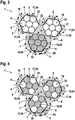
- FIG. 3 shows a schematic representation of a cross section through a cord 1 according to the invention, wherein the cross-sectional plane as in FIG. 1 indicated according to the section AA runs.
- the inventive cord 1 is as in FIG. 3 shown from a first yarn 2, a second yarn 3 and a further yarn 16 end twisted.
- the first yarn 2 consists of seven filaments 24, all seven filaments 24 consisting of PVDF 17 and having the surface 19 of the filaments 24 of the first yarn 2.
- the second yarn 3 consists of seven filaments 24, wherein all seven filaments 24 are made of polyester 18 and have the surface 20 of the filaments 24 of the second yarn 3.
- FIG. 3 shows a schematic representation of a cross section through a cord 1 according to the invention, wherein the cross-sectional plane as in FIG. 1 indicated according to the section AA runs.
- the inventive cord 1 is as in FIG. 3 shown from a first yarn 2, a second yarn 3 and a further yarn 16 end twisted.
- the first yarn 2 consists of seven filaments 24, all seven
- the further yarn 16 consists of seven filaments 24, all seven filaments 24 consisting of PVDF 17 and having the surface 21 of the filaments 24 of the further yarn 16.
- the three yarns 2, 3, 16 are in FIG. 3 surrounded by an adhesion-promoting layer 5, wherein the adhesion-promoting layer 5 is a dispersion and consists of a dispersion matrix 6 comprising resorcin-formaldehyde and a dispersed phase 7 consisting of natural latex particles.
- the adhesion-promoting layer 5 can not be uniformly distributed in an optimal manner by means of the dip method, such as, for example, a method according to the invention.
- exposed surfaces 23 on the various surfaces 19, 20, 21 or between the individual filaments 24 of a yarn 2, 3, 16 can still be present even after the dip process. It is preferred if at least half of the surfaces 19, 20, 21 or at least half of the middle outer surface 22 is covered by the adhesion-promoting layer 5. Especially it is preferred if at least 90% of the surfaces 19, 20, 21 or at least 90% of the middle outer surface 22 is covered by the adhesion-promoting layer 5. This leads to improved adhesion between a cord 1 according to the invention and a gumming layer, such as, for example, the gumming layer 9 of a reinforcement layer 10 for elastomeric products FIG. 5 ,
- FIG. 4 shows a schematic representation of a cross section through a cord 1 according to the invention, wherein the cross-sectional plane as in FIG. 2 indicated according to the section BB runs.
- the inventive cord 1 is as in FIG. 4 shown from a first yarn 2, a second yarn 3 and a further yarn 16 end twisted.
- the first yarn 2 consists of seven filaments 24, the seven filaments 24 being made of PVDF 17 or polyester 18 and having the surface 19 of the filaments 24 of the first yarn 2.
- the second yarn 3 consists of seven filaments 24, the seven filaments 24 being made of PVDF 17 or polyester 18 and having the surface 20 of the filaments 24 of the second yarn 3.
- FIG. 4 shows a schematic representation of a cross section through a cord 1 according to the invention, wherein the cross-sectional plane as in FIG. 2 indicated according to the section BB runs.
- the inventive cord 1 is as in FIG. 4 shown from a first yarn 2, a second yarn 3 and a further yarn 16 end twisted.
- the first yarn 2 consists of seven
- the further yarn 16 consists of seven filaments 24, wherein the seven filaments 24 consist of PVDF 17 or of polyester 18 and have the surface 21 of the filaments 24 of the further yarn 16.
- the three yarns 2, 3, 16 are in FIG. 4 surrounded by an adhesion-promoting layer 5, wherein the adhesion-promoting layer 5 is a dispersion and consists of a dispersion matrix 6 comprising resorcin-formaldehyde and a dispersed phase 7 consisting of natural latex particles.
- the adhesion-promoting layer 5 can not be uniformly distributed in an optimal manner by means of the dip method, such as, for example, a method according to the invention.
- exposed surfaces 23 on the various surfaces 19, 20, 21 or between the individual filaments 24 of a yarn 2, 3, 16 can still be present even after the dip process. It is preferred if at least half of the surfaces 19, 20, 21 or at least half of the middle outer surface 22 is covered by the adhesion-promoting layer 5. It is particularly preferred if at least 90% of the surfaces 19, 20, 21 or at least 90% of the middle outer surface 22 of the adhesion-promoting layer 5 is covered. This leads to improved adhesion between a cord 1 according to the invention and a gumming layer, such as, for example, the gumming layer 9 of a reinforcement layer 10 for elastomeric products FIG. 5 ,
- FIG. 5 shows a section of a reinforcement layer 10 according to the invention for elastomeric products, which represents a reinforcement layer 14 according to the invention with a cord 1 according to the invention.
- 14 are three cords in a Kunststoff ceremoniesslage 9, wherein the middle of the 3 cords is a cord 1 according to the invention.
- the cord 1 according to the invention is end-twisted with a first yarn 2 and a second yarn 3, the first yarn 2 consisting of filaments of PVDF 17 and the second yarn 3 of filaments of polyester 18.
- the two other shown cords consist exclusively of filaments made of polyester 18.
- FIG. 6 shows a vehicle pneumatic tire 11 according to the invention on a road surface 15.
- the vehicle pneumatic tire 11 according to the invention comprises a tread 12, a belt layer 13 and a reinforcement layer 10, 14 in FIG FIG. 6 is the deformation on the footprint of the pneumatic vehicle tire 11, which is caused by the weight of the pneumatic vehicle tire 11 in the direction of the road surface 15.
- This deformation is a cause, a possibility of how deformation of the cord of the invention can occur.
- no measuring unit for measuring the electrical signal, no transmission unit for transmitting the measured electrical voltage between the first and second and no control unit for processing the transmitted measurement of the electrical voltage between the first and second yarn are shown in FIG.
Landscapes
- Engineering & Computer Science (AREA)
- Mechanical Engineering (AREA)
- Textile Engineering (AREA)
- Ropes Or Cables (AREA)
- Tires In General (AREA)
- Treatments For Attaching Organic Compounds To Fibrous Goods (AREA)
Abstract
Die Erfindung betrifft einen Cord zur Verwendung als Festigkeitsträger in einer Festigkeitsträgerlage, insbesondere einer Gürtelbandage und/oder Karkasse eines Fahrzeugluftreifens, umfassend zumindest ein erstes Garn und ein zweites Garn, wobei der erste und das zweite Garn miteinander endverdreht sind,dadurch gekennzeichnet, dass zumindest ein Filament des ersten Garns des Cordes, eine Mehrheit der Filamente des ersten Garns oder sämtliche Filamente des ersten Garns aus Polyvinylidenfluorid bestehen und die Oberfläche des Cordes zumindest teilweise von eine haftvermittelnde Schicht bestehend aus einer Dispersion bedeckt ist, wobei die haftvermittelnde Schicht aus einer Dispersion besteht und die Dispersion eine Dispersionsmatrix und eine dispergierte Phase umfasst. Die Erfindung betrifft auch eine Festigkeitsträgerlage, Fahrzeugluftreifen, Transportbänder, Luftfederbälge, Antriebsriemen und Schläuche jeweils umfassend den Cord sowie die Verwendung des Cords zum Messen. Auch betrifft die Erfindung ein Verfahren zum Messen und ein Verfahren zur Herstellung des Cordes.The invention relates to a cord for use as a reinforcement in a reinforcement layer, in particular a belt bandage and / or carcass of a pneumatic vehicle tire, comprising at least a first yarn and a second yarn, the first and the second yarn being twisted together, characterized in that at least one Filament of the first yarn of the cord, a majority of the filaments of the first yarn or all filaments of the first yarn are made of polyvinylidene fluoride and the surface of the cord is at least partially covered by an adhesion-promoting layer consisting of a dispersion, the adhesion-promoting layer consisting of a dispersion and the dispersion comprises a dispersion matrix and a dispersed phase. The invention also relates to a reinforcement layer, pneumatic vehicle tires, conveyor belts, air bellows, drive belts and hoses each comprising the cord and the use of the cord for measuring. The invention also relates to a method for measuring and a method for producing the cord.
Description
Die Erfindung betrifft einen Cord zur Verwendung als Festigkeitsträger in einer Festigkeitsträgerlage, insbesondere einer Gürtelbandage und/oder Karkasse eines Fahrzeugluftreifens, umfassend zumindest ein erstes Garn und ein zweites Garn, wobei der erste und das zweite Garn miteinander endverdreht sind. Die Erfindung betrifft auch eine Festigkeitsträgerlage, Fahrzeugluftreifen, Transportbänder, Luftfederbälge, Antriebsriemen und Schläuche jeweils umfassend den Cord sowie die Verwendung des Cords zum Messen. Auch betrifft die Erfindung ein Verfahren zum Messen und ein Verfahren zur Herstellung des Cordes.The invention relates to a cord for use as a strength member in a reinforcement layer, in particular a belt bandage and / or carcass of a pneumatic vehicle tire, comprising at least a first yarn and a second yarn, wherein the first and the second yarn are end twisted together. The invention also relates to a reinforcing layer, pneumatic vehicle tires, conveyor belts, air spring bellows, drive belts and hoses each comprising the cord and the use of the cord for measuring. The invention also relates to a method for measuring and a method for producing the cord.
In jüngster Zeit gewinnen in Reifen eingebaute Sensoren zunehmend an Bedeutung. Die in Reifen eingebaute Sensoren sollen dabei nicht mehr nur den Luftdruck des Reifens während des Fahrens messen, sondern auch andere Reifeneigenschaften, wie den Rollwiderstand, den Reibwiderstand oder den Abrieb. Dazu ist es nötig neuartige Sensorkonzepte zu entwickeln, welche die gewünschten Eigenschaften messen können und/oder keine Nachteile mit sich bringen. Solche Nachteile können beispielsweise Unwuchten im Reifen sein, welche durch den zusätzlichen Einbau eines Sensors in den Reifen entstehen.Recently, sensors installed in tires are becoming increasingly important. The built-in tire sensors are not only to measure the tire pressure during driving, but also other tire properties, such as rolling resistance, frictional resistance or abrasion. For this purpose, it is necessary to develop novel sensor concepts which can measure the desired properties and / or bring no disadvantages. Such disadvantages may be, for example, imbalances in the tire, which are caused by the additional installation of a sensor in the tire.
Eine Aufgabe, die der Erfindung zugrunde liegt, besteht darin, einen Cord zur Verwendung als Festigkeitsträger in einer Festigkeitsträgerlage bereitzustellen, welche verschiedene Reifeneigenschaften, insbesondere den Rollwiderstand, den Reibwiderstand oder den Abrieb, messen kann.It is an object of the present invention to provide a cord for use as a strength member in a reinforcing layer which has various types Tire properties, in particular the rolling resistance, the frictional resistance or the abrasion, can measure.
Gelöst wird diese Aufgabe erfindungsgemäß durch einen Cord zur Verwendung als Festigkeitsträger in einer Festigkeitsträgerlage, insbesondere einer Gürtelbandage und/oder Karkasse eines Fahrzeugluftreifens, umfassend zumindest ein erstes Garn und ein zweites Garn, wobei der erste und das zweite Garn miteinander endverdreht sind,
dadurch gekennzeichnet, dass
- zumindest ein Filament des ersten Garns des Cordes, eine Mehrheit der Filamente des ersten Garns oder sämtliche Filamente des ersten Garns aus Polyvinylidenfluorid bestehen
und - die Oberfläche zumindest des ersten Garns und des zweiten Garns zumindest teilweise von eine haftvermittelnde Schicht bestehend aus einer Dispersion bedeckt ist, wobei die Dispersion mindestens eine Dispersionsmatrix und mindestens eine dispergierte Phase umfasst.
characterized in that
- at least one filament of the first yarn of the cord, a majority of the filaments of the first yarn or all filaments of the first yarn of polyvinylidene fluoride exist
and - the surface of at least the first yarn and the second yarn is at least partially covered by an adhesion-promoting layer consisting of a dispersion, the dispersion comprising at least one dispersion matrix and at least one dispersed phase.
Es war eine hervorragende Leistung der vorliegenden Erfindung, erkannt zu haben, dass die Verwendung eines Filamenten oder eines Garns aus Polyvinylidenfluorid, kurz: PVDF, mit der vorstehend beschriebenen haftvermittelnden Schicht in einem Reifen verwendet werden kann, um verschiedene Reifeneigenschaften, insbesondere den Rollwiderstand, den Reibwiderstand oder den Abrieb, zu messen. Ohne an eine wissenschaftliche Theorie gebunden sein zu wollen, wurde entdeckt dass bei den gewöhnlichen Deformationen eines Festigkeitsträgers in einem Reifen PVDF einen ausreichend großen Piezo-ähnlichen Effekt aufweist, um ein elektrisches Signal zu erhalten. Zu diesen gewöhnlichen Deformationen eines Festigkeitsträgers in einem Reifen gehört beispielsweise die mechanische Spannung eines Festigkeitsträgers, welche sich proportional zum Innenluftdruck des Reifens verändert oder auch die dynamischen und entweder gedämpften oder ungedämpften Schwingungen eines Festigkeitsträgers, welche beim Rollen eines Reifens auftreten. Aus den vorstehend beschriebenen Schwingungen kann es möglich sein, den Abrieb bzw. den Reibwidersand und/oder den Rollwiderstand eines Fahrzeugluftreifens während des Fahrbetriebs zu kontrollieren. Für eine ausreichende Übertragung der mechanischen Kräfte von dem die Fahrbahnoberfläche kontaktierenden Laufstreifen auf ein vorstehend beschriebenen Garn in einem erfindungsgemäßen Fahrzeugluftreifen, ist es wichtig, dass das Garn zumindest teilweise mit einer haftvermittelnden Schicht wie vorstehend beschrieben überzogen wird. Im Rahmen der vorliegenden Erfindung sollte die Oberfläche der Filamente des ersten Garns zumindest teilweise mit einer vorstehend beschriebenen haftvermittelnden Schicht bedeckt sein. Umfasst auch das zweite Garn PVDF, so ist es vorteilhaft, wenn auch der die Oberfläche des zweiten Garns zumindest teilweise mit einer haftvermittelnden Schicht bedeckt ist. Besonders bevorzugt sind die Oberflächen sämtlicher Garne eines erfindungsgemäßen Cord zumindest teilweise mit der vorstehend beschriebenen haftvermittelnden Schicht bedeckt. Ausreichend ist es auch, wenn zumindest die mittlere äußere Oberfläche sämtlicher Garne des erfindungsmäßen Cordes von der vorstehend oder nachstehend beschriebenen haftvermittelnden Schicht bedeckt ist. Im Rahmen der vorliegenden Erfindung ist die mittlere äußere Oberfläche sämtlicher Garne eines erfindungsmäßen Cordes die von der Mitte eines erfindungsgemäßen Cordes aus ausliegenden Oberflächen der Filamente der Garne des erfindungsmäßen Cordes, wie sie beispielsweise in
Bevorzugt ist auch ein Cord wie vorstehend beschrieben, wobei die Dispersion genau eine Dispersionsmatrix und genau eine dispergierte Phase umfasst oder wobei besonders bevorzugt die Dispersion aus genau einer Dispersionsmatrix und genau einer dispergierte Phase besteht.Also preferred is a cord as described above, wherein the dispersion comprises exactly one dispersion matrix and exactly one dispersed phase, or more preferably wherein the dispersion consists of exactly one dispersion matrix and exactly one dispersed phase.
Bevorzugt ist auch ein Cord wie vorstehend beschrieben, wobei ein Filament des ersten Garns des Cordes, eine Mehrheit der Filamente des ersten Garns oder sämtliche Filamente des ersten Garns aus einem anderen Piezo-Material als Polyvinylidenfluorid bestehen oder solche Stoffe umfassen. Solche anderen Piezo-Materialen sind beispielsweise Polyvinylidenchlorid, Blei-Zirkonat-Titanat (PZT), Bariumtitanat, Polyvinylchlorid und Polyvinylfluorid.Also preferred is a cord as described above, wherein a filament of the first yarn of the cord, a majority of the filaments of the first yarn or all filaments of the first yarn consist of a piezo material other than polyvinylidene fluoride or comprise such substances. Such other piezo materials are, for example, polyvinylidene chloride, lead zirconate titanate (PZT), barium titanate, polyvinyl chloride and polyvinyl fluoride.
Bevorzugt ist ein Cord wie vorstehend beschrieben oder wie vorstehend als bevorzugt beschrieben, wobei die haftvermittelnde Schicht eine Schichtdicke im Bereich von 10 nm bis 1 mm aufweist, bevorzugt im Bereich von 100 nm bis 100 µm, besonders bevorzugt im Bereich von 1 µm bis 10 µm.Preferred is a cord as described above or as described above as preferred, wherein the adhesion-promoting layer has a layer thickness in the range of 10 nm to 1 mm, preferably in the range of 100 nm to 100 .mu.m, particularly preferably in the range of 1 .mu.m to 10 .mu.m ,
Der Vorteil der vorstehend beschriebenen Bereiche der Schicht dicken der haftvermittelnden Schicht ist, dass sie ein Optimum zwischen der Steifigkeit der Corde und einer ausreichenden Kraftübertragung zwischen dem Laufstreifen und dem Cord darstellen.The advantage of the above-described ranges of layer thicknesses of the adhesion-promoting layer is that they represent an optimum between the stiffness of the cords and sufficient force transmission between the tread and the cord.
Bevorzugt ist ein Cord wie vorstehend beschrieben oder wie vorstehend als bevorzugt beschrieben, wobei die haftvermittelnde Schicht zumindest die Hälfte der Oberfläche des ersten und zweiten Garns bedeckt, bevorzugt zumindest 90 % der Oberfläche des ersten und des zweiten Garns.Preferably, a cord is as described above or as described above as preferred wherein the adhesion promoting layer covers at least half of the surface of the first and second yarns, preferably at least 90% of the surface of the first and second yarns.
Der vorstehend beschriebene Aspekt der vorliegenden Erfindung ist, dass diese Oberflächenbedeckungen ein Optimum zwischen der Steifigkeit der Corde und einer ausreichenden Kraftübertragung zwischen dem Laufstreifen und dem Cord darstellen.The aspect of the present invention described above is that these surface coverings represent an optimum between the rigidity of the cords and sufficient force transmission between the tread and the cord.
Im Rahmen der vorliegenden Erfindung umfasst die Oberfläche sämtlicher Filamente eines Garns auch die Oberfläche des besagten Garns. Im Rahmen der vorliegenden Erfindung ist die Oberfläche eines Garns bevorzugt die von der Mitte eines Garns aus ausliegenden Oberflächen der Filamente des besagten Garns.In the context of the present invention, the surface of all filaments of a yarn also includes the surface of said yarn. In the context of the present invention, the surface of a yarn is preferably the surface of the filaments of the said yarn lying from the center of a yarn.
Bevorzugt ist ein Cord wie vorstehend beschrieben oder wie vorstehend als bevorzugt beschrieben, wobei die Dispersionsmatrix Resorcin-Formaldehyd und/oder die dispergierte Phase Kautschuklatex umfasst.Preferably, a cord is as described above or as described above as preferred wherein the dispersion matrix comprises resorcinol-formaldehyde and / or the dispersed phase rubber latex.
Eine haftvermittelnde Schicht eines erfindungsgemäßen Cordes wie vorstehend beschrieben kann überraschenderweise mit den üblicherweise eingesetzten so genannten RFL-Dips hergestellt werden. Der Fachmann hätte nicht erwartet, dass die vorstehend beschriebene Dispersionsmatrix so gut an PVDF-Oberflächen halten, dass der erfindungsgemäße Cord zur Messung der vorstehend beschriebenen Reifeneigenschaften geeignet ist.An adhesion-promoting layer of a cordage according to the invention as described above can be produced, surprisingly, with the commonly used so-called RFL dips. The person skilled in the art would not have expected that the dispersion matrix described above adhere so well to PVDF surfaces that the Cord according to the invention is suitable for measuring the tire properties described above.
Bevorzugt ist es, wenn die Dispersionsmatrix hauptsächlich oder gänzlich aus Resorcin-Formaldehyd besteht und/oder die dispergierte Phase hauptsächlich oder gänzlich aus Kautschuklatex besteht, bevorzugt aus Kautschuklatex-Partikeln.It is preferred if the dispersion matrix mainly or wholly consists of resorcinol-formaldehyde and / or the dispersed phase consists mainly or wholly of rubber latex, preferably of rubber latex particles.
Die dispergierte Phase die dabei bevorzugt in Form von im Wesentlichen rundlichen Partikeln aus Kautschuklatex vor, wobei sie bevorzugt dazu geeignet sind, für eine möglichst gute Haftung zwischen der haftvermittelnden Schicht eines erfindungsgemäßen Cordes und der den Cord umgebenden Gummikomponenten zu garantieren.The dispersed phase preferably precedes in the form of substantially round particles of rubber latex, and they are preferably suitable for ensuring the best possible adhesion between the adhesion-promoting layer of a corduroy according to the invention and the rubber components surrounding the corduroy.
Bevorzugt ist ein Cord wie vorstehend beschrieben oder wie vorstehend als bevorzugt beschrieben, dadurch gekennzeichnet, dass die Kautschuklatex-Partikel eine mittlere Partikelgröße im Bereich von 0,3 bis 30 mm aufweisen, bevorzugt im Bereich von 0,425 bis 20 mm, besonders bevorzugt im Bereich von 0,7 bis 2,5 mm. Die Bestimmung wird vorzugsweise mit einer Schüttelzeit von 5 Minuten und mit Sieben, welche Maschenweiten von 0,2 mm, 0,4 mm, 0,6 mm, 0,8 mm, 1 mm, 1,5 mm, 2 mm, 3 mm, 5 mm, 15 mm, 25 mm und 35 mm durchgeführt (entsprechend wären gemäß der weiter unten diskutierten Messmethode d1 = 0,1 mm, d2 = 0,3 mm, d3 = 0,5 mm usw. bis d10 = 20 mm und d11 = 30 mm).Preferred is a cord as described above or as described above as preferred, characterized in that the rubber latex particles have an average particle size in the range of 0.3 to 30 mm, preferably in the range of 0.425 to 20 mm, particularly preferably in the range of 0.7 to 2.5 mm. The determination is preferably carried out with a shaking time of 5 minutes and with sieves having mesh sizes of 0.2 mm, 0.4 mm, 0.6 mm, 0.8 mm, 1 mm, 1.5 mm, 2 mm, 3 mm , 5 mm, 15 mm, 25 mm and 35 mm (accordingly, according to the measuring method discussed below, d 1 = 0.1 mm, d 2 = 0.3 mm, d 3 = 0.5 mm, etc., to d 10 = 20 mm and d 11 = 30 mm).
Ganz besonders bevorzugt ist ein Cord wie vorstehend beschrieben (oder wie vorstehend als bevorzugt beschrieben), dadurch gekennzeichnet, dass die Kautschuklatex-Partikel
- eine mittlere Partikelgröße im Bereich von 0,3 bis 30 mm aufweisen, wobei einzelne Kautschuklatex-Partikel nicht größer als 500 mm sind, bevorzugt nicht größer als 100 mm,
- besonders bevorzugt eine mittlere Partikelgröße im Bereich von 0,425 bis 20 mm aufweisen, wobei einzelne Kautschuklatex-Partikel nicht größer als 30 mm sind,
- ganz besonders bevorzugt eine mittlere Partikelgröße im Bereich von 0,7 bis 2,5 mm, wobei einzelne Kautschuklatex-Partikel nicht größer als 10 mm sind,
- insbesondere bevorzugt eine mittlere Partikelgröße im Bereich von 0,7 bis 2,5 mm, wobei einzelne Kautschuklatex-Partikel nicht größer als 5 mm sind.
- have an average particle size in the range of 0.3 to 30 mm, wherein individual rubber latex particles are not larger than 500 mm, preferably not larger than 100 mm,
- more preferably have an average particle size in the range of 0.425 to 20 mm, wherein individual rubber latex particles are not greater than 30 mm,
- most preferably an average particle size in the range of 0.7 to 2.5 mm, wherein individual rubber latex particles are not larger than 10 mm,
- Particularly preferred is an average particle size in the range of 0.7 to 2.5 mm, wherein individual rubber latex particles are not greater than 5 mm.
Ganz besonders bevorzugt ist auch ein Cord wie vorstehend beschrieben oder wie vorstehend als bevorzugt bzw. als besonders bevorzugt beschrieben dadurch gekennzeichnet, dass
- die Kautschuklatex-Partikel eine mittlere Partikelgröße im Bereich von 0,3 bis 30 mm aufweisen und mindestens 50 Massenprozent, vorzugsweise mindestens 90 Massenprozent, der Kautschuklatex-Partikel eine Partikelgröße im Bereich von 0,01 mm bis 50 mm aufweisen,
- bevorzugt die Kautschuklatex-Partikel eine mittlere Partikelgröße von 0,425 bis 20 mm und mindestens 50 Massenprozent, vorzugsweise mindestens 90 Massenprozent, der Kautschuklatex-Partikel eine Partikelgröße im Bereich von 0,05 mm bis 30 mm aufweisen,
- besonders bevorzugt die Kautschuklatex-Partikel eine mittlere Partikelgröße von 0,7 bis 2,5 mm und mindestens 50 Massenprozent, vorzugsweise mindestens 90 Massenprozent, der Kautschuklatex-Partikel eine Partikelgröße im Bereich von 0,1 mm bis 10 mm oder ganz besonders bevorzugt im Bereich von 1 mm bis 6 mm aufweisen.
- the rubber latex particles have an average particle size in the range of 0.3 to 30 mm and at least 50% by mass, preferably at least 90% by mass, of the rubber latex particles have a particle size in the range from 0.01 mm to 50 mm,
- the rubber latex particle preferably has a mean particle size of 0.425 to 20 mm and at least 50 percent by mass, preferably at least 90 percent by mass, of the rubber latex particles having a particle size in the range from 0.05 mm to 30 mm,
- the rubber latex particles particularly preferably have an average particle size of 0.7 to 2.5 mm and at least 50% by mass, preferably at least 90% by mass, of the rubber latex particles having a particle size in the range from 0.1 mm to 10 mm or very particularly preferably in the range from 1 mm to 6 mm.
Im Rahmen der vorliegenden Erfindung ist die Partikelgröße eines einzigen vulkanisierten Kautschukpartikels bevorzugt die Distanz zwischen den zwei am weitesten voneinander entfernten Punkte des einen vulkanisierten Kautschukpartikels, welche mit einem Licht- oder Elektronenmikroskop aus dem Stand der Technik gemessen werden kann.In the present invention, the particle size of a single vulcanized rubber particle is preferably the distance between the two most distant points of the one vulcanized rubber particle, which can be measured with a light or electron microscope of the prior art.
Bevorzugt ist ein Cord wie vorstehend beschrieben oder wie vorstehend als bevorzugt beschrieben, wobei
- zumindest ein Filament des zweiten oder eines weiteren Garns des Cordes oder eine Mehrheit der Filamente des zweiten Garns aus Polyvinylidenfluorid bestehen und/oder
- zumindest ein Filament des zweiten oder eines weiteren Garns des Cordes, eine Mehrheit der Filamente des zweiten oder eines weiteren Garns oder sämtliche Filamente des zweiten oder eines weiteren Garns aus ein Material, zwei Materialien,
- drei oder mehr Materialien umfassen ausgesucht aus der Gruppe bestehend aus Polyethylen, Aramid, Polyester und Polyamid, wie beispielsweise Polyamid 6 und Polyamid 6.6.
- at least one filament of the second or another yarn of the cord or a majority of the filaments of the second yarn consist of polyvinylidene fluoride and / or
- at least one filament of the second or another yarn of the cord, a majority of the filaments of the second or another yarn or all the filaments of the second or another yarn of one material, two materials,
- Three or more materials include selected from the group consisting of polyethylene, aramid, polyester, and polyamide, such as
polyamide 6 and polyamide 6.6.
Bevorzugt umfassen die vorstehend beschriebenen eins, zwei Materialien, drei oder mehr Materialien auch anderen Piezo-Materialen, wie beispielsweise Solche anderen Piezo-Materialen sind beispielsweise Polyvinylidenchlorid, Blei-Zirkonat-Titanat (PZT), Bariumtitanat, Polyvinylchlorid und Polyvinylfluorid. Bevorzugt sind Blei-Zirkonat-Titanat (PZT), Bariumtitanat und Polyvinylchlorid.Preferably, the above-described one, two materials, three or more materials also include other piezo materials, such as, for example, other polyvinylidene chloride, polyvinylidene chloride, lead zirconate titanate (PZT), barium titanate, polyvinyl chloride, and polyvinyl fluoride. Preference is given to lead zirconate titanate (PZT), barium titanate and polyvinyl chloride.
Der vorstehend beschriebene Aspekt der vorliegenden Erfindung ist, dass durch die Verwendung von Filamenten aus verschiedenen Materialien die Eigenschaften des Festigkeitsträger besser an einen Reifen angepasst werden können und trotzdem PVDF erfindungsgemäß eingesetzt werden kann.The above-described aspect of the present invention is that by using filaments of different materials, the properties of the strength member can be better adapted to a tire, and yet PVDF can be used according to the invention.
Bevorzugt ist es jedoch, ein Cord wie vorstehend beschrieben oder wie vorstehend als bevorzugt beschrieben, wobei
- zumindest ein Filament des ersten Garns des Cordes, eine Mehrheit der Filamente des ersten Garns oder sämtliche Filamente des ersten Garns aus Polyvinylidenfluorid bestehen
und - zumindest ein Filament des zweiten, eine Mehrheit der Filamente des zweiten Garns oder sämtliche Filamente des zweiten Garns aus Polyvinylidenfluorid bestehen.
- at least one filament of the first yarn of the cord, a majority of the filaments of the first yarn or all filaments of the first yarn of polyvinylidene fluoride exist
and - at least one filament of the second, a majority of the filaments of the second yarn or all filaments of the second yarn of polyvinylidene fluoride consist.
Der vorstehend beschriebene Aspekt der vorliegenden Erfindung ist, dass das entstehende Signal aufgrund der Deformation des erfindungsgemäßen Cordes vergrößert wird.The above-described aspect of the present invention is that the resulting signal is increased due to the deformation of the cord of the present invention.
Bevorzugt ist ein Cord wie vorstehend beschrieben oder wie vorstehend als bevorzugt beschrieben, wobei
das erste und/oder zweite Garn ein Garn mit einer Feinheit von 200 bis 7000 dtex ist, bevorzugt eine Feinheit von 1000 bis 3500 dtex, wobei sämtliche Filamente des ersten Garns bevorzugt aus PVDF bestehen,
und/oder
das erste und/oder zweite Garn ein Garn mit einer Feinheit von 100 bis 1000 dtex ist, bevorzugt eine Feinheit von 100 bis 500 dtex.Preferably, a cord is as described above or as described above as preferred, wherein
the first and / or second yarn is a yarn having a fineness of 200 to 7000 dtex, preferably a fineness of 1000 to 3500 dtex, all filaments of the first yarn preferably consisting of PVDF,
and or
the first and / or second yarn is a yarn having a fineness of 100 to 1000 dtex, preferably a fineness of 100 to 500 dtex.
Der vorstehend beschriebene Aspekt der vorliegenden Erfindung ist, dass mit einem vorstehend beschriebenen erfindungsgemäßen Cord sowohl ein relativ starkes Signal aufgrund des Piezo-Effektes erreicht werden kann und gleichzeitig Reifen mit besonders hoher Uniformität hergestellt werden können.The above-described aspect of the present invention is that with a cord according to the invention described above, both a relatively strong signal due to the piezoelectric effect can be achieved and at the same time tires with a particularly high uniformity can be produced.
Bevorzugt ist ein Cord wie vorstehend beschrieben oder wie vorstehend als bevorzugt beschrieben, wobei der erste und das zweite Garn sowie optional weitere Garne mit 200 bis 700 tpm, bevorzugt 300 bis 400 tpm, miteinander endverdreht sind.Preferred is a cord as described above or as described above as preferred, wherein the first and the second yarn and optionally further yarns with 200 to 700 tpm, preferably 300 to 400 tpm, are end-twisted together.
Der vorstehend beschriebene Aspekt der vorliegenden Erfindung ist, dass Reifen mit besonders hoher Uniformität sowie weiteren positiven Reifeneigenschaften hergestellt werden können.The above-described aspect of the present invention is that tires having particularly high uniformity as well as other positive tire properties can be produced.
Bevorzugt ist ein Cord wie vorstehend beschrieben oder wie vorstehend als bevorzugt beschrieben, wobei der Cord zur Verwendung als Festigkeitsträger in einer Festigkeitsträgerlage geeignet ist und zumindest ein erstes Garn wie vorstehend beschrieben oder wie vorstehend als bevorzugt beschrieben umfassen und ein HybridCord ist und
- wobei das erste Garn mit einem oder zwei anderen Garnen zu dem Hybridcord endverdreht sind
oder - wobei zumindest ein Filament eines zweiten Garns des Cordes, eine Mehrheit der Filamente des zweiten Garns oder sämtliche Filamente des zweiten Garns aus Polyvinylidenfluorid bestehen und der erste und zweite Garn mit einem anderen Garn zu dem Hybridcord endverdreht sind.
- wherein the first yarn is end-twisted with one or two other yarns to the hybrid cord
or - wherein at least one filament of a second yarn of the cord, a majority of the filaments of the second yarn or all the filaments of the second yarn Polyvinylidenfluorid exist and the first and second yarn are twisted with another yarn to the hybrid cord.
Der vorstehend beschriebene Aspekt der vorliegenden Erfindung ist, dass Hybridcord die im Stand der Technik bekannten positiven Eigenschaften aufweisen.The above-described aspect of the present invention is that hybrid cord have the positive properties known in the art.
Im Rahmen der vorliegenden Erfindung bezeichnet der Ausdruck "ein anderer Garn" ein Garn, welches aus einem anderen Material als das erste Garn eines erfindungsgemäßen Cordes besteht. Der Ausdruck "ein weiteres Garn" umfasst sowohl die vorstehende Bedeutung eines anderen Garns sowie Garne, welche aus dem gleichen Material wie das erste Garn eines erfindungsgemäßen Cordes bestehen.In the context of the present invention, the term "another yarn" denotes a yarn which consists of a different material than the first yarn of a cord according to the invention. The term "another yarn" includes both the above meaning of another yarn and yarns made of the same material as the first yarn of a cord of the invention.
In besonders hohem Maße bevorzugt ist Cord wie vorstehend beschrieben, umfassend zumindest ein erstes Garn und ein zweites Garn, wobei der erste und das zweite Garn miteinander endverdreht sind, dadurch gekennzeichnet, dass
- sämtliche Filamente des ersten Garns aus Polyvinylidenfluorid bestehen und
- die Oberfläche des Cordes zumindest teilweise von eine haftvermittelnde Schicht bestehend aus einer Dispersion bedeckt ist, wobei die haftvermittelnde Schicht aus einer Dispersion besteht und die Dispersion eine Dispersionsmatrix und eine dispergierte Phase umfasst,
- sämtliche Filamente des zweiten Garns aus Polyvinylidenfluorid bestehen,
- die haftvermittelnde Schicht eine Schichtdicke im Bereich von 100 nm bis 100 µm aufweist,
- die Dispersionsmatrix Resorcin-Formaldehyd und die dispergierte Phase aus Kautschuklatex besteht,
- der erste und das zweite Garn eine Feinheit von 1000 bis 3500 dtex aufweist, und
- der erste und das zweite Garn sowie optional weitere Garne mit 300 bis 400 tpm, miteinander endverdreht sind.
- all filaments of the first yarn consist of polyvinylidene fluoride and
- the surface of the cord is at least partially covered by an adhesion-promoting layer consisting of a dispersion, the adhesion-promoting layer consisting of a dispersion and the dispersion comprising a dispersion matrix and a dispersed phase,
- all filaments of the second yarn consist of polyvinylidene fluoride,
- the adhesion-promoting layer has a layer thickness in the range from 100 nm to 100 μm,
- the dispersion matrix resorcinol-formaldehyde and the dispersed rubber latex phase,
- the first and second yarns have a fineness of 1000 to 3500 dtex, and
- the first and the second yarn as well as optionally further yarns with 300 to 400 tpm, are end-twisted together.
Die vorstehend beschriebenen vorteilhaften Aspekte eines erfindungsgemäßen Cord zur Verwendung als Festigkeitsträger in einer Festigkeitsträgerlage gelten auch für sämtliche Aspekte nachstehend beschriebene Festigkeitsträgerlagen, Fahrzeugluftreifen, Transportbänder, Luftfederbälge, Antriebsriemen und Schläuchen und die nachstehend diskutierten vorteilhaften Aspekte erfindungsgemäßer Festigkeitsträgerlagen, Fahrzeugluftreifen, Transportbänder, Luftfederbälge, Antriebsriemen und Schläuchen gelten entsprechend für sämtliche Aspekte eines erfindungsgemäßen Cord zur Verwendung als Festigkeitsträger in einer Festigkeitsträgerlage.The above-described advantageous aspects of a cord according to the invention for use as reinforcement in a reinforcement layer also apply to all aspects of reinforcement layers described below, pneumatic vehicle tires, conveyor belts, air bellows, drive belts and hoses and the below discussed advantageous aspects of reinforcement layers according to the invention, pneumatic vehicle tires, conveyor belts, air bags, drive belts and Hoses apply correspondingly to all aspects of a cord according to the invention for use as strength carrier in a reinforcement layer.
Die Erfindung betrifft auch eine Festigkeitsträgerlage für elastomere Erzeugnisse, bevorzugt für Fahrzeugluftreifen Transportbändern, Luftfederbälgen, Antriebsriemen und Schläuchen, besonders bevorzugt für Fahrzeugluftreifen, aufweisend zumindest einen Cord wie vorstehend beschrieben oder wie vorstehend als bevorzugt beschrieben. Bevorzugt weisen die vorstehend genannten Gegenstände jedoch mehrheitlich einen Cord wie vorstehend beschrieben oder wie vorstehend als bevorzugt beschrieben auf oder umfassen ausschließlich Corde wie vorstehend beschrieben oder wie vorstehend als bevorzugt beschrieben.The invention also relates to a reinforcing layer for elastomeric products, preferably for pneumatic vehicle tires, conveyor belts, air bellows, drive belts and hoses, particularly preferably for pneumatic vehicle tires, comprising at least one cord as described above or as described above as preferred. However, the above-mentioned objects preferably have a cord in majority as described above or as described above as being preferred or comprise exclusively cords as described above or as described above as being preferred.
Die Erfindung betrifft auch einen Fahrzeugluftreifen, ein Transportband, ein Luftfederbalg, ein Antriebsriemen und einen Schlauch, jeweils zumindest einen Cord wie vorstehend beschriebenen oder vorstehend als bevorzugt beschriebenen aufweisend.The invention also relates to a pneumatic vehicle tire, a conveyor belt, an air spring bellows, a drive belt and a hose, each having at least one cord as described above or described above as being preferred.
Bevorzugt ist ein vorstehend beschriebener Fahrzeugluftreifen, ein vorstehend beschriebenes Transportband, ein vorstehend beschriebener Luftfederbalg, ein vorstehend beschriebener Antriebsriemen oder ein vorstehend beschriebener Schlauch, zusätzlich umfassend
- eine Messeinheit zum Messen des elektrischen Signals, bevorzugt der elektrischen Spannung, zwischen dem ersten und zweiten Garn eines Cords,
- eine Übertragungseinheit zum Übertragen der gemessenen elektrischen Spannung zwischen dem ersten und zweiten Garn eines Cords
und - eine Steuereinheit zum Verarbeiten der gesendeten Messung der elektrischen Spannung zwischen dem ersten und zweiten Garn eines Cords.
- a measuring unit for measuring the electrical signal, preferably the electrical voltage, between the first and second yarn of a cord,
- a transmission unit for transmitting the measured electric voltage between the first and second yarns of a cord
and - a control unit for processing the transmitted measurement of the electrical voltage between the first and second yarn of a cord.
Die vorstehend beschriebenen vorteilhaften Aspekte erfindungsgemäßer Corde, Festigkeitsträgerlagen, Fahrzeugluftreifen, Transportbänder, Luftfederbälge, Antriebsriemen und Schläuchen gelten auch für sämtliche Aspekte einer nachstehend beschriebenen Verwendung und die nachstehend diskutierten vorteilhaften Aspekte erfindungsgemäßer Verwendungen gelten entsprechend für sämtliche Aspekte erfindungsgemäßer Corde, Festigkeitsträgerlagen, Fahrzeugluftreifen, Transportbänder, Luftfederbälge, Antriebsriemen und Schläuchen.The above-described advantageous aspects of cords, reinforcement layers, pneumatic tires, conveyor belts, pneumatic bellows, drive belts and hoses according to the invention also apply to all aspects of a use described below and the advantageous aspects of uses according to the invention discussed below apply correspondingly to all aspects of cords according to the invention, reinforcement layers, pneumatic vehicle tires, conveyor belts, Air bellows, drive belts and hoses.
Die Erfindung betrifft auch eine Verwendung eines Cords wie vorstehend beschrieben oder wie vorstehend als bevorzugt beschrieben
- zum Messen des Innenluftdrucks eines Fahrzeugluftreifens,
- zum Messen des Abriebs eines Fahrzeugluftreifens
oder - zum Messen des Rollwiderstandes oder des Reibwiderstandes zur Fahrbahnoberfläche eines Fahrzeugluftreifens.
- for measuring the internal air pressure of a pneumatic vehicle tire,
- for measuring the abrasion of a pneumatic vehicle tire
or - for measuring the rolling resistance or the frictional resistance to the road surface of a pneumatic vehicle tire.
Bevorzugt wird der Cords wie vorstehend beschrieben oder wie vorstehend als bevorzugt beschrieben zum Messen des Innenluftdrucks eines Fahrzeugluftreifens und/oder zum Messen des Rollwiderstandes und des Reibwiderstandes zur Fahrbahnoberfläche eines Fahrzeugluftreifens verwendet.Preferably, the cords as described above or as described above are preferably used for measuring the inner air pressure of a pneumatic vehicle tire and / or for measuring the rolling resistance and the frictional resistance to the road surface of a pneumatic vehicle tire.
Wie bereits vorstehend beschrieben kann
- aus der mechanischen Spannung eines Festigkeitsträgers in einem Reifen, Rückschlüsse auf den Reifeninnendruck erhalten werden
oder - aus den dynamischen und entweder gedämpften oder ungedämpften Schwingungen eines Festigkeitsträgers Rückschlüsse auf den Abrieb bzw. den Reibwidersand oder den Rollwiderstand eines Fahrzeugluftreifens während des Fahrbetriebs erhalten werden.
- From the mechanical stress of a strength member in a tire, conclusions about the tire pressure can be obtained
or - from the dynamic and either damped or undamped oscillations of a reinforcing material conclusions about the abrasion or the Reibwidersand or the rolling resistance of a pneumatic vehicle tire are obtained during driving.
Die vorstehend beschriebenen vorteilhaften Aspekte erfindungsgemäßer Corde, Festigkeitsträgerlagen, Fahrzeugluftreifen, Transportbänder, Luftfederbälge, Antriebsriemen und Schläuchen sowie erfindungsgemäßer Verwendungen gelten auch für sämtliche Aspekte nachstehend beschriebener Verfahren und die nachstehend diskutierten vorteilhaften Aspekte erfindungsgemäßer Verfahren gelten entsprechend für sämtliche Aspekte erfindungsgemäßer Corde, Festigkeitsträgerlagen, Fahrzeugluftreifen, Transportbänder, Luftfederbälge, Antriebsriemen und Schläuchen sowie erfindungsgemäßer Verwendungen.The above-described advantageous aspects of cords according to the invention, reinforcing material layers, pneumatic vehicle tires, conveyor belts, pneumatic bellows, drive belts and hoses as well as uses according to the invention also apply to all aspects of the methods described below and the advantageous aspects of methods according to the invention discussed below apply correspondingly to all aspects of cords, reinforcement layers, pneumatic vehicle tires according to the invention, Conveyor belts, air bellows, drive belts and hoses and uses according to the invention.
Die Erfindung betrifft auch ein Verfahren zum Messen des Innenluftdrucks eines Fahrzeugluftreifens, des Abriebs eines Fahrzeugluftreifens oder zum Messen des Rollwiderstandes und des Reibwiderstandes zur Fahrbahnoberfläche eines Fahrzeugluftreifens, umfassend die folgenden Schritte:
- Bereitstellen oder Herstellen eines Fahrzeugluftreifens aufweisend einen Cord wie vorstehend beschrieben oder wie vorstehend als bevorzugt beschrieben,
- Messen der elektrischen Spannung zwischen dem ersten und zweiten Garn des Cords mittels einer Messeinheit,
- Senden der gemessenen elektrischen Spannung zwischen dem ersten und zweiten Garn mittels einer Sendeeinheit an eine Steuereinheit
und - Verarbeiten der gesendeten Messung der elektrischen Spannung mittels einer Steuereinheit.
- Providing or producing a pneumatic vehicle tire having a cord as described above or as described above as being preferred
- Measuring the electrical voltage between the first and second yarn of the cord by means of a measuring unit,
- Sending the measured electrical voltage between the first and second yarn by means of a transmitting unit to a control unit
and - Processing the transmitted measurement of the electrical voltage by means of a control unit.
Die Erfindung betrifft auch ein Verfahren zur Herstellung eines Cordes für einen Fahrzeugluftreifen oder einer gummierten Festigkeitsträgerlage oder eines Fahrzeugluftreifens:
- a) Verzwirnen mindestens eines PVDF-Garnes mit einem weiteren Garn zu einem Cord,
- b) Dippen des Cordes in eine wässrige Lösung umfassend Resorcin-Formaldehyd und Kautschuklatex,
- c) Trocknen des gedippten Cordes,
- sodass die Oberfläche des Cordes zumindest teilweise von eine haftvermittelnde Schicht bestehend aus einer Dispersion bedeckt ist, wobei die haftvermittelnde Schicht aus einer Dispersion besteht und die Dispersion eine Dispersionsmatrix und eine dispergierte Phase umfasst,
- und bevorzugt sodass ein vorstehend beschriebener oder vorstehend als bevorzugt beschriebener Cord entsteht,
- d) optionales Weiterverarbeiten des Cordes zu einer gummierten Festigkeitsträgerlage für Fahrzeugluftreifen oder bevorzugt zu einem Fahrzeugluftreifen.
- a) twisting at least one PVDF yarn with another yarn into a cord,
- b) dipping the cord in an aqueous solution comprising resorcinol-formaldehyde and rubber latex,
- c) drying the dipped cordes,
- so that the surface of the cord is at least partially covered by an adhesion-promoting layer consisting of a dispersion, wherein the adhesion-promoting layer consists of a dispersion and the dispersion comprises a dispersion matrix and a dispersed phase,
- and preferably so that a cord described above or described above as preferred arises,
- d) optional further processing of the cord to a rubberized reinforcement layer for pneumatic vehicle tires or preferably to a pneumatic vehicle tire.
Bevorzugt ist auch ein Verfahren zur Herstellung eines Cordes für einen Fahrzeugluftreifen oder einer gummierten Festigkeitsträgerlage oder eines Fahrzeugluftreifens, wie vorstehend beschreiben, wobei das Verfahren zusätzlich mindestens einen der folgenden Schritte umfasst:
- e) Einbauen einer Messeinheit zum Messen einer Spannungsänderung eines Garn aus PVDF in den Cord, in die gummierte Festigkeitsträgerlage oder den Fahrzeugluftreifen
und/oder - f) Einbauen eine Übertragungseinheit zum Übertragen einer gemessenen Spannungsänderung in den Cord, in die gummierte Festigkeitsträgerlage oder den Fahrzeugluftreifen.
- e) installing a measuring unit for measuring a change in tension of a yarn of PVDF in the cord, in the rubberized reinforcement layer or the pneumatic vehicle tire
and or - f) Incorporate a transfer unit for transferring a measured change in tension into the cord, into the rubberized reinforcing layer or the pneumatic vehicle tire.
Besonders bevorzugt wird die vorstehend beschriebene Messeinheit oder die vorstehende steht beschriebene Übertragungseinheit bevorzugt aus Indien Reifen ein gedruckten Elektronikkomponenten hergestellt und somit problemlos in den Reifen integriert.Particularly preferably, the above-described measuring unit or the above-described transfer unit described is preferably produced from India tires a printed electronic components and thus easily integrated into the tire.
Der Vorteil des vorstehend beschriebenen Aspekts ist, dass die erfindungsgemäße Verwendung eines Cordes ohne großen Umbau des Reifens oder den Einbau unnötiger elektronischer Bestandteile erreicht werden kann.The advantage of the aspect described above is that the use of a cord according to the invention can be achieved without major modification of the tire or the installation of unnecessary electronic components.
- Figur 1:FIG. 1:
- Schematisch dargestellter erfindungsgemäßer Cord endverdreht aus einem ersten Garn aus PVDF und einem zweiten Garn aus Polyester;Schematically illustrated inventive cord end twisted from a first yarn of PVDF and a second yarn of polyester;
- Figur 2:FIG. 2:
- Schematisch dargestellter erfindungsgemäßer Cord bestehend aus zwei endverdrehten Hybridgarnen, wobei jeder Hybridgarn aus PVDF-Filamenten und aus Polyester-Filamenten besteht;Schematically illustrated inventive cord consisting of two end twisted hybrid yarns, each hybrid yarn consisting of PVDF filaments and polyester filaments;
- Figur 3:FIG. 3:
-
Schematisch dargestellter Querschnitt eines erfindungsgemäßen Cordes mit haftvermittelnder Schicht bestehend aus einer Dispersion, wobei die Querschnittebene gemäß dem Schnitt A-A in
Figur 1 verläuft;Schematically represented cross-section of a cordage according to the invention with adhesion-promoting layer consisting of a dispersion, wherein the cross-sectional plane according to the section AA inFIG. 1 runs; - Figur 4:FIG. 4:
-
Schematisch dargestellter Querschnitt eines erfindungsgemäßen Cordes mit haftvermittelnder Schicht bestehend aus einer Dispersion umgeben von einer Gummierungslage, wobei die Querschnittebene gemäß dem Schnitt B-B in
Figur 2 verläuft;Schematically represented cross-section of a cordage according to the invention with adhesion-promoting layer consisting of a dispersion surrounded by a gumming layer, wherein the cross-sectional plane according to the section BB inFIG. 2 runs; - Figur 5:FIG. 5:
- Schematisch dargestellte erfindungsgemäße Verstärkungslage umfassend sowohl einen erfindungsgemäßen Cord bestehend aus zwei endverdrehten Garnen als auch zwei weitere Corde;Schematically illustrated reinforcing layer according to the invention comprises both a cord according to the invention consisting of two end twisted yarns and two further cords;
- Figur 6:FIG. 6:
- Ansicht auf die Verformung eines erfindungsgemäßen Cordes in einem Reifen während des Fahrbetriebs.View on the deformation of a cordage according to the invention in a tire during driving.
Zudem ist in
Zudem ist in
- 1 erfindungsgemäßer Cord1 inventive cord
- 2 erster Garn2 first yarn
- 3 zweiter Garn3 second yarn
- 4 Oberfläche des Cords4 surface of the cord
- 5 haftvermittelnde Schicht5 adhesion-promoting layer
- 6 Dispersionsmatrix6 Dispersion matrix
- 7 dispergierte Phase, Naturlatex-Partikel7 dispersed phase, natural latex particles
- 8 Schichtdicke der haftvermittelnden Schicht8 layer thickness of the adhesion-promoting layer
- 9 Gummierungslage9 gum layer
- 10 Festigkeitsträgerlage für elastomere Erzeugnisse10 reinforcement layer for elastomeric products
- 11 Fahrzeugluftreifen11 pneumatic vehicle tires
- 12 Lauffläche des Fahrzeugluftreifens12 tread of the pneumatic vehicle tire
- 13 Gürtellage; Gürtelbandage13 belt layer; belt bandage
- 14 Festigkeitsträgerlage mit einem erfindungsgemäßen Cord14 reinforcement layer with a cord according to the invention
- 15 Fahrbahnoberfläche15 road surface
- 16 weiterer Garn16 more yarn
- 17 PVDF; Polyvinylidenfluorid17 PVDF; polyvinylidene fluoride
- 18 Polyester18 polyester
- 19 Oberfläche des ersten Garns19 surface of the first yarn
- 20 Oberfläche des zweiten Garns20 surface of the second yarn
- 21 Oberfläche des weiteren Garns21 Surface of the other yarn
- 22 mittlere äußere Oberfläche des erfindungsgemäßen Cordes22 mean outer surface of the cordage according to the invention
- 23 freiliegende Oberfläche23 exposed surface
- 24 Filament24 filament
Claims (13)
dadurch gekennzeichnet, dass
und
characterized in that
and
und/oder
and or
zumindest ein Filament (24) des zweiten oder eines weiteren Garns (3, 16) des Cordes (1) oder eine Mehrheit der Filamente (24) des zweiten Garns (2) aus Polyvinylidenfluorid (17) bestehen
und/oder
zumindest ein Filament (24) des zweiten oder eines weiteren Garns (3, 16) des Cordes (1), eine Mehrheit der Filamente (24) des zweiten oder eines weiteren Garns (3, 16) oder sämtliche Filamente (24) des zweiten oder eines weiteren Garns (3, 16) aus ein Material, zwei Materialien, drei oder mehr Materialien umfassen ausgesucht aus der Gruppe bestehend aus Polyethylen, Aramid, Polyamid und Polyester.Cord according to one of the preceding claims, wherein
at least one filament (24) of the second or further yarn (3, 16) of the cord (1) or a majority of the filaments (24) of the second yarn (2) are made of polyvinylidene fluoride (17)
and or
at least one filament (24) of the second or further yarn (3, 16) of the cord (1), a majority of the filaments (24) of the second or further yarn (3, 16) or all the filaments (24) of the second or another yarn (3, 16) of one material, two materials, three or more materials selected from the group consisting of polyethylene, aramid, polyamide and polyester.
der erste und/oder zweite Garn (2, 3) ein Garn mit einer Feinheit von 200 bis 7000 dtex ist, bevorzugt eine Feinheit von 1000 bis 3500 dtex,
und/oder
der erste und/oder zweite Garn (2, 3) ein Garn mit einer Feinheit von 100 bis 1000 dtex ist, bevorzugt eine Feinheit von 100 bis 500 dtex.Cord according to one of the preceding claims, wherein
the first and / or second yarn (2, 3) is a yarn having a fineness of 200 to 7000 dtex, preferably a fineness of 1000 to 3500 dtex,
and or
the first and / or second yarn (2, 3) is a yarn having a fineness of 100 to 1000 dtex, preferably a fineness of 100 to 500 dtex.
oder
or
Applications Claiming Priority (1)
| Application Number | Priority Date | Filing Date | Title |
|---|---|---|---|
| DE102018207736.3A DE102018207736A1 (en) | 2018-05-17 | 2018-05-17 | A cord for use as a strength member in a reinforcing layer comprising at least a first yarn and a second yarn, wherein the first and second yarns are end-twisted together, their use for measuring and a hybrid cord, a reinforcing layer, pneumatic vehicle tires and methods of manufacture |
Publications (2)
| Publication Number | Publication Date |
|---|---|
| EP3569747A1 true EP3569747A1 (en) | 2019-11-20 |
| EP3569747B1 EP3569747B1 (en) | 2021-01-20 |
Family
ID=66105134
Family Applications (1)
| Application Number | Title | Priority Date | Filing Date |
|---|---|---|---|
| EP19168558.5A Active EP3569747B1 (en) | 2018-05-17 | 2019-04-11 | Cord for use as a support in a stability support layer comprising at least a first and a second yarn, where the first and second yarn are twisted together at the end, its use for measuring and a hybrid cord, a stability support layer, vehicle tyre and method for the production thereof |
Country Status (2)
| Country | Link |
|---|---|
| EP (1) | EP3569747B1 (en) |
| DE (1) | DE102018207736A1 (en) |
Citations (2)
| Publication number | Priority date | Publication date | Assignee | Title |
|---|---|---|---|---|
| DE102007005281A1 (en) * | 2007-02-02 | 2008-08-07 | Continental Aktiengesellschaft | Reinforcing layer of hybrid cords for elastomeric products, in particular for the belt bandage of pneumatic vehicle tires |
| DE102010037328A1 (en) * | 2010-09-06 | 2012-03-08 | Continental Reifen Deutschland Gmbh | Pneumatic vehicle tire of radial design comprises carcass, components adjacent to it, and thread-like elements on one of two surfaces of carcass, that discharges air enclosed between carcass and adjacent components during tire construction |
-
2018
- 2018-05-17 DE DE102018207736.3A patent/DE102018207736A1/en active Pending
-
2019
- 2019-04-11 EP EP19168558.5A patent/EP3569747B1/en active Active
Patent Citations (2)
| Publication number | Priority date | Publication date | Assignee | Title |
|---|---|---|---|---|
| DE102007005281A1 (en) * | 2007-02-02 | 2008-08-07 | Continental Aktiengesellschaft | Reinforcing layer of hybrid cords for elastomeric products, in particular for the belt bandage of pneumatic vehicle tires |
| DE102010037328A1 (en) * | 2010-09-06 | 2012-03-08 | Continental Reifen Deutschland Gmbh | Pneumatic vehicle tire of radial design comprises carcass, components adjacent to it, and thread-like elements on one of two surfaces of carcass, that discharges air enclosed between carcass and adjacent components during tire construction |
Also Published As
| Publication number | Publication date |
|---|---|
| DE102018207736A1 (en) | 2019-11-21 |
| EP3569747B1 (en) | 2021-01-20 |
Similar Documents
| Publication | Publication Date | Title |
|---|---|---|
| DE60017978T2 (en) | Steel rope for reinforcing rubber articles, and method and apparatus for producing such steel cables | |
| DE102007025490A1 (en) | Reinforcing layer of hybrid cords for elastomeric products, in particular for the belt bandage of pneumatic vehicle tires | |
| DE2739484A1 (en) | STEEL REINFORCEMENT CORDS FOR TIRES | |
| EP3006228B1 (en) | Hybrid cord for use as a rigidity support in a component of a vehicle pneumatic tyre and vehicle pneumatic tyre | |
| DE69122898T2 (en) | Fiber reinforced rubber | |
| EP2114697B1 (en) | Reinforcement layer of hybrid cords for elastomeric products, particularly for the belt bandage of pneumatic vehicle tyres | |
| EP2113397B1 (en) | Stability beam layout made from hybrid cords for elastomeric products, in particular for the belt of vehicle pneumatic tyres | |
| EP3269562B1 (en) | Method for producing a strip-shaped rubber strip reinforced with a strengthening support | |
| EP3569747B1 (en) | Cord for use as a support in a stability support layer comprising at least a first and a second yarn, where the first and second yarn are twisted together at the end, its use for measuring and a hybrid cord, a stability support layer, vehicle tyre and method for the production thereof | |
| EP0476451B1 (en) | Pneumatic spring bellow formed from a dynamically loadable rubber composite material | |
| WO2018095614A1 (en) | Pneumatic vehicle tyre with a belt ply having steel monofilaments | |
| DE68904153T2 (en) | THREAD COMPOSITE MATERIAL WITH CONCENTRIC THREAD LAYERS. | |
| EP2198080B1 (en) | Reinforcement layer made of hybrid cords for elastomeric products | |
| EP2492114B1 (en) | Pneumatic tyres for a vehicle | |
| EP3323634B1 (en) | Hybrid cord for use as a reinforcing support in a component of a vehicle pneumatic tyre and vehicle pneumatic tyre | |
| DE102007025489A1 (en) | Reinforcing layer of hybrid cords for elastomeric products, in particular for the belt bandage of pneumatic vehicle tires | |
| DE102019207014A1 (en) | Reinforcement layer for a pneumatic vehicle tire | |
| EP3724388B1 (en) | Hybrid cord for use as a strength member in a belt bandage of a pneumatic vehicle tire and use | |
| DE102016224839A1 (en) | Braided reinforcing tape for a reinforcing layer of pneumatic vehicle tires | |
| DE19709884A1 (en) | Economical reinforcing steel cord for belt plies and carcasses of vehicular tyres | |
| DE102020206965A1 (en) | Reinforcement layer and pneumatic vehicle tires | |
| DE102019217355A1 (en) | Tape-like, strength-carrier-reinforced rubber strips and pneumatic vehicle tires | |
| DE102016201926A1 (en) | Process for producing a material web | |
| DE112020002051T5 (en) | Steel cables, tape stacks and tires | |
| DE102013108390A1 (en) | Reinforcing layer of hybrid cords for elastomeric products, in particular for the belt bandage of pneumatic vehicle tires |
Legal Events
| Date | Code | Title | Description |
|---|---|---|---|
| PUAI | Public reference made under article 153(3) epc to a published international application that has entered the european phase |
Free format text: ORIGINAL CODE: 0009012 |
|
| STAA | Information on the status of an ep patent application or granted ep patent |
Free format text: STATUS: THE APPLICATION HAS BEEN PUBLISHED |
|
| AK | Designated contracting states |
Kind code of ref document: A1 Designated state(s): AL AT BE BG CH CY CZ DE DK EE ES FI FR GB GR HR HU IE IS IT LI LT LU LV MC MK MT NL NO PL PT RO RS SE SI SK SM TR |
|
| AX | Request for extension of the european patent |
Extension state: BA ME |
|
| STAA | Information on the status of an ep patent application or granted ep patent |
Free format text: STATUS: REQUEST FOR EXAMINATION WAS MADE |
|
| 17P | Request for examination filed |
Effective date: 20200520 |
|
| RBV | Designated contracting states (corrected) |
Designated state(s): AL AT BE BG CH CY CZ DE DK EE ES FI FR GB GR HR HU IE IS IT LI LT LU LV MC MK MT NL NO PL PT RO RS SE SI SK SM TR |
|
| GRAP | Despatch of communication of intention to grant a patent |
Free format text: ORIGINAL CODE: EPIDOSNIGR1 |
|
| STAA | Information on the status of an ep patent application or granted ep patent |
Free format text: STATUS: GRANT OF PATENT IS INTENDED |
|
| INTG | Intention to grant announced |
Effective date: 20201013 |
|
| GRAS | Grant fee paid |
Free format text: ORIGINAL CODE: EPIDOSNIGR3 |
|
| GRAA | (expected) grant |
Free format text: ORIGINAL CODE: 0009210 |
|
| STAA | Information on the status of an ep patent application or granted ep patent |
Free format text: STATUS: THE PATENT HAS BEEN GRANTED |
|
| RAP1 | Party data changed (applicant data changed or rights of an application transferred) |
Owner name: CONTINENTAL REIFEN DEUTSCHLAND GMBH |
|
| AK | Designated contracting states |
Kind code of ref document: B1 Designated state(s): AL AT BE BG CH CY CZ DE DK EE ES FI FR GB GR HR HU IE IS IT LI LT LU LV MC MK MT NL NO PL PT RO RS SE SI SK SM TR |
|
| REG | Reference to a national code |
Ref country code: GB Ref legal event code: FG4D Free format text: NOT ENGLISH |
|
| REG | Reference to a national code |
Ref country code: CH Ref legal event code: EP |
|
| REG | Reference to a national code |
Ref country code: DE Ref legal event code: R096 Ref document number: 502019000713 Country of ref document: DE |
|
| REG | Reference to a national code |
Ref country code: AT Ref legal event code: REF Ref document number: 1356483 Country of ref document: AT Kind code of ref document: T Effective date: 20210215 |
|
| REG | Reference to a national code |
Ref country code: IE Ref legal event code: FG4D Free format text: LANGUAGE OF EP DOCUMENT: GERMAN |
|
| REG | Reference to a national code |
Ref country code: NL Ref legal event code: FP |
|
| REG | Reference to a national code |
Ref country code: LT Ref legal event code: MG9D |
|
| PG25 | Lapsed in a contracting state [announced via postgrant information from national office to epo] |
Ref country code: BG Free format text: LAPSE BECAUSE OF FAILURE TO SUBMIT A TRANSLATION OF THE DESCRIPTION OR TO PAY THE FEE WITHIN THE PRESCRIBED TIME-LIMIT Effective date: 20210420 Ref country code: GR Free format text: LAPSE BECAUSE OF FAILURE TO SUBMIT A TRANSLATION OF THE DESCRIPTION OR TO PAY THE FEE WITHIN THE PRESCRIBED TIME-LIMIT Effective date: 20210421 Ref country code: FI Free format text: LAPSE BECAUSE OF FAILURE TO SUBMIT A TRANSLATION OF THE DESCRIPTION OR TO PAY THE FEE WITHIN THE PRESCRIBED TIME-LIMIT Effective date: 20210120 Ref country code: HR Free format text: LAPSE BECAUSE OF FAILURE TO SUBMIT A TRANSLATION OF THE DESCRIPTION OR TO PAY THE FEE WITHIN THE PRESCRIBED TIME-LIMIT Effective date: 20210120 Ref country code: PT Free format text: LAPSE BECAUSE OF FAILURE TO SUBMIT A TRANSLATION OF THE DESCRIPTION OR TO PAY THE FEE WITHIN THE PRESCRIBED TIME-LIMIT Effective date: 20210520 Ref country code: NO Free format text: LAPSE BECAUSE OF FAILURE TO SUBMIT A TRANSLATION OF THE DESCRIPTION OR TO PAY THE FEE WITHIN THE PRESCRIBED TIME-LIMIT Effective date: 20210420 Ref country code: LT Free format text: LAPSE BECAUSE OF FAILURE TO SUBMIT A TRANSLATION OF THE DESCRIPTION OR TO PAY THE FEE WITHIN THE PRESCRIBED TIME-LIMIT Effective date: 20210120 |
|
| PG25 | Lapsed in a contracting state [announced via postgrant information from national office to epo] |
Ref country code: PL Free format text: LAPSE BECAUSE OF FAILURE TO SUBMIT A TRANSLATION OF THE DESCRIPTION OR TO PAY THE FEE WITHIN THE PRESCRIBED TIME-LIMIT Effective date: 20210120 Ref country code: RS Free format text: LAPSE BECAUSE OF FAILURE TO SUBMIT A TRANSLATION OF THE DESCRIPTION OR TO PAY THE FEE WITHIN THE PRESCRIBED TIME-LIMIT Effective date: 20210120 Ref country code: LV Free format text: LAPSE BECAUSE OF FAILURE TO SUBMIT A TRANSLATION OF THE DESCRIPTION OR TO PAY THE FEE WITHIN THE PRESCRIBED TIME-LIMIT Effective date: 20210120 Ref country code: SE Free format text: LAPSE BECAUSE OF FAILURE TO SUBMIT A TRANSLATION OF THE DESCRIPTION OR TO PAY THE FEE WITHIN THE PRESCRIBED TIME-LIMIT Effective date: 20210120 |
|
| PG25 | Lapsed in a contracting state [announced via postgrant information from national office to epo] |
Ref country code: IS Free format text: LAPSE BECAUSE OF FAILURE TO SUBMIT A TRANSLATION OF THE DESCRIPTION OR TO PAY THE FEE WITHIN THE PRESCRIBED TIME-LIMIT Effective date: 20210520 |
|
| REG | Reference to a national code |
Ref country code: DE Ref legal event code: R097 Ref document number: 502019000713 Country of ref document: DE |
|
| PG25 | Lapsed in a contracting state [announced via postgrant information from national office to epo] |
Ref country code: EE Free format text: LAPSE BECAUSE OF FAILURE TO SUBMIT A TRANSLATION OF THE DESCRIPTION OR TO PAY THE FEE WITHIN THE PRESCRIBED TIME-LIMIT Effective date: 20210120 Ref country code: CZ Free format text: LAPSE BECAUSE OF FAILURE TO SUBMIT A TRANSLATION OF THE DESCRIPTION OR TO PAY THE FEE WITHIN THE PRESCRIBED TIME-LIMIT Effective date: 20210120 Ref country code: SM Free format text: LAPSE BECAUSE OF FAILURE TO SUBMIT A TRANSLATION OF THE DESCRIPTION OR TO PAY THE FEE WITHIN THE PRESCRIBED TIME-LIMIT Effective date: 20210120 |
|
| PLBE | No opposition filed within time limit |
Free format text: ORIGINAL CODE: 0009261 |
|
| STAA | Information on the status of an ep patent application or granted ep patent |
Free format text: STATUS: NO OPPOSITION FILED WITHIN TIME LIMIT |
|
| PG25 | Lapsed in a contracting state [announced via postgrant information from national office to epo] |
Ref country code: MC Free format text: LAPSE BECAUSE OF FAILURE TO SUBMIT A TRANSLATION OF THE DESCRIPTION OR TO PAY THE FEE WITHIN THE PRESCRIBED TIME-LIMIT Effective date: 20210120 Ref country code: DK Free format text: LAPSE BECAUSE OF FAILURE TO SUBMIT A TRANSLATION OF THE DESCRIPTION OR TO PAY THE FEE WITHIN THE PRESCRIBED TIME-LIMIT Effective date: 20210120 Ref country code: RO Free format text: LAPSE BECAUSE OF FAILURE TO SUBMIT A TRANSLATION OF THE DESCRIPTION OR TO PAY THE FEE WITHIN THE PRESCRIBED TIME-LIMIT Effective date: 20210120 Ref country code: SK Free format text: LAPSE BECAUSE OF FAILURE TO SUBMIT A TRANSLATION OF THE DESCRIPTION OR TO PAY THE FEE WITHIN THE PRESCRIBED TIME-LIMIT Effective date: 20210120 |
|
| 26N | No opposition filed |
Effective date: 20211021 |
|
| PG25 | Lapsed in a contracting state [announced via postgrant information from national office to epo] |
Ref country code: LU Free format text: LAPSE BECAUSE OF NON-PAYMENT OF DUE FEES Effective date: 20210411 |
|
| REG | Reference to a national code |
Ref country code: BE Ref legal event code: MM Effective date: 20210430 |
|
| PG25 | Lapsed in a contracting state [announced via postgrant information from national office to epo] |
Ref country code: ES Free format text: LAPSE BECAUSE OF FAILURE TO SUBMIT A TRANSLATION OF THE DESCRIPTION OR TO PAY THE FEE WITHIN THE PRESCRIBED TIME-LIMIT Effective date: 20210120 Ref country code: AL Free format text: LAPSE BECAUSE OF FAILURE TO SUBMIT A TRANSLATION OF THE DESCRIPTION OR TO PAY THE FEE WITHIN THE PRESCRIBED TIME-LIMIT Effective date: 20210120 |
|
| PG25 | Lapsed in a contracting state [announced via postgrant information from national office to epo] |
Ref country code: SI Free format text: LAPSE BECAUSE OF FAILURE TO SUBMIT A TRANSLATION OF THE DESCRIPTION OR TO PAY THE FEE WITHIN THE PRESCRIBED TIME-LIMIT Effective date: 20210120 |
|
| PG25 | Lapsed in a contracting state [announced via postgrant information from national office to epo] |
Ref country code: IT Free format text: LAPSE BECAUSE OF FAILURE TO SUBMIT A TRANSLATION OF THE DESCRIPTION OR TO PAY THE FEE WITHIN THE PRESCRIBED TIME-LIMIT Effective date: 20210120 Ref country code: IE Free format text: LAPSE BECAUSE OF NON-PAYMENT OF DUE FEES Effective date: 20210411 |
|
| PG25 | Lapsed in a contracting state [announced via postgrant information from national office to epo] |
Ref country code: IS Free format text: LAPSE BECAUSE OF FAILURE TO SUBMIT A TRANSLATION OF THE DESCRIPTION OR TO PAY THE FEE WITHIN THE PRESCRIBED TIME-LIMIT Effective date: 20210520 |
|
| PG25 | Lapsed in a contracting state [announced via postgrant information from national office to epo] |
Ref country code: BE Free format text: LAPSE BECAUSE OF NON-PAYMENT OF DUE FEES Effective date: 20210430 |
|
| REG | Reference to a national code |
Ref country code: CH Ref legal event code: PL |
|
| PG25 | Lapsed in a contracting state [announced via postgrant information from national office to epo] |
Ref country code: LI Free format text: LAPSE BECAUSE OF NON-PAYMENT OF DUE FEES Effective date: 20220430 Ref country code: CH Free format text: LAPSE BECAUSE OF NON-PAYMENT OF DUE FEES Effective date: 20220430 |
|
| PG25 | Lapsed in a contracting state [announced via postgrant information from national office to epo] |
Ref country code: CY Free format text: LAPSE BECAUSE OF FAILURE TO SUBMIT A TRANSLATION OF THE DESCRIPTION OR TO PAY THE FEE WITHIN THE PRESCRIBED TIME-LIMIT Effective date: 20210120 |
|
| PG25 | Lapsed in a contracting state [announced via postgrant information from national office to epo] |
Ref country code: HU Free format text: LAPSE BECAUSE OF FAILURE TO SUBMIT A TRANSLATION OF THE DESCRIPTION OR TO PAY THE FEE WITHIN THE PRESCRIBED TIME-LIMIT; INVALID AB INITIO Effective date: 20190411 |
|
| REG | Reference to a national code |
Ref country code: DE Ref legal event code: R081 Ref document number: 502019000713 Country of ref document: DE Owner name: CONTINENTAL REIFEN DEUTSCHLAND GMBH, DE Free format text: FORMER OWNER: CONTINENTAL REIFEN DEUTSCHLAND GMBH, 30165 HANNOVER, DE |
|
| PG25 | Lapsed in a contracting state [announced via postgrant information from national office to epo] |
Ref country code: MK Free format text: LAPSE BECAUSE OF FAILURE TO SUBMIT A TRANSLATION OF THE DESCRIPTION OR TO PAY THE FEE WITHIN THE PRESCRIBED TIME-LIMIT Effective date: 20210120 |
|
| PGFP | Annual fee paid to national office [announced via postgrant information from national office to epo] |
Ref country code: NL Payment date: 20240418 Year of fee payment: 6 |
|
| PGFP | Annual fee paid to national office [announced via postgrant information from national office to epo] |
Ref country code: GB Payment date: 20240419 Year of fee payment: 6 |
|
| PGFP | Annual fee paid to national office [announced via postgrant information from national office to epo] |
Ref country code: DE Payment date: 20240430 Year of fee payment: 6 |
|
| PGFP | Annual fee paid to national office [announced via postgrant information from national office to epo] |
Ref country code: FR Payment date: 20240425 Year of fee payment: 6 |