EP3569724A1 - High strength seamless stainless steel pipe and production method therefor - Google Patents
High strength seamless stainless steel pipe and production method therefor Download PDFInfo
- Publication number
- EP3569724A1 EP3569724A1 EP17890889.3A EP17890889A EP3569724A1 EP 3569724 A1 EP3569724 A1 EP 3569724A1 EP 17890889 A EP17890889 A EP 17890889A EP 3569724 A1 EP3569724 A1 EP 3569724A1
- Authority
- EP
- European Patent Office
- Prior art keywords
- less
- steel pipe
- air cooling
- stainless steel
- temperature
- Prior art date
- Legal status (The legal status is an assumption and is not a legal conclusion. Google has not performed a legal analysis and makes no representation as to the accuracy of the status listed.)
- Granted
Links
Classifications
-
- C—CHEMISTRY; METALLURGY
- C21—METALLURGY OF IRON
- C21D—MODIFYING THE PHYSICAL STRUCTURE OF FERROUS METALS; GENERAL DEVICES FOR HEAT TREATMENT OF FERROUS OR NON-FERROUS METALS OR ALLOYS; MAKING METAL MALLEABLE, e.g. BY DECARBURISATION OR TEMPERING
- C21D9/00—Heat treatment, e.g. annealing, hardening, quenching or tempering, adapted for particular articles; Furnaces therefor
- C21D9/08—Heat treatment, e.g. annealing, hardening, quenching or tempering, adapted for particular articles; Furnaces therefor for tubular bodies or pipes
- C21D9/085—Cooling or quenching
-
- C—CHEMISTRY; METALLURGY
- C21—METALLURGY OF IRON
- C21D—MODIFYING THE PHYSICAL STRUCTURE OF FERROUS METALS; GENERAL DEVICES FOR HEAT TREATMENT OF FERROUS OR NON-FERROUS METALS OR ALLOYS; MAKING METAL MALLEABLE, e.g. BY DECARBURISATION OR TEMPERING
- C21D9/00—Heat treatment, e.g. annealing, hardening, quenching or tempering, adapted for particular articles; Furnaces therefor
- C21D9/08—Heat treatment, e.g. annealing, hardening, quenching or tempering, adapted for particular articles; Furnaces therefor for tubular bodies or pipes
-
- C—CHEMISTRY; METALLURGY
- C21—METALLURGY OF IRON
- C21D—MODIFYING THE PHYSICAL STRUCTURE OF FERROUS METALS; GENERAL DEVICES FOR HEAT TREATMENT OF FERROUS OR NON-FERROUS METALS OR ALLOYS; MAKING METAL MALLEABLE, e.g. BY DECARBURISATION OR TEMPERING
- C21D1/00—General methods or devices for heat treatment, e.g. annealing, hardening, quenching or tempering
- C21D1/18—Hardening; Quenching with or without subsequent tempering
- C21D1/19—Hardening; Quenching with or without subsequent tempering by interrupted quenching
- C21D1/22—Martempering
-
- C—CHEMISTRY; METALLURGY
- C21—METALLURGY OF IRON
- C21D—MODIFYING THE PHYSICAL STRUCTURE OF FERROUS METALS; GENERAL DEVICES FOR HEAT TREATMENT OF FERROUS OR NON-FERROUS METALS OR ALLOYS; MAKING METAL MALLEABLE, e.g. BY DECARBURISATION OR TEMPERING
- C21D6/00—Heat treatment of ferrous alloys
- C21D6/004—Heat treatment of ferrous alloys containing Cr and Ni
-
- C—CHEMISTRY; METALLURGY
- C21—METALLURGY OF IRON
- C21D—MODIFYING THE PHYSICAL STRUCTURE OF FERROUS METALS; GENERAL DEVICES FOR HEAT TREATMENT OF FERROUS OR NON-FERROUS METALS OR ALLOYS; MAKING METAL MALLEABLE, e.g. BY DECARBURISATION OR TEMPERING
- C21D6/00—Heat treatment of ferrous alloys
- C21D6/005—Heat treatment of ferrous alloys containing Mn
-
- C—CHEMISTRY; METALLURGY
- C21—METALLURGY OF IRON
- C21D—MODIFYING THE PHYSICAL STRUCTURE OF FERROUS METALS; GENERAL DEVICES FOR HEAT TREATMENT OF FERROUS OR NON-FERROUS METALS OR ALLOYS; MAKING METAL MALLEABLE, e.g. BY DECARBURISATION OR TEMPERING
- C21D6/00—Heat treatment of ferrous alloys
- C21D6/007—Heat treatment of ferrous alloys containing Co
-
- C—CHEMISTRY; METALLURGY
- C21—METALLURGY OF IRON
- C21D—MODIFYING THE PHYSICAL STRUCTURE OF FERROUS METALS; GENERAL DEVICES FOR HEAT TREATMENT OF FERROUS OR NON-FERROUS METALS OR ALLOYS; MAKING METAL MALLEABLE, e.g. BY DECARBURISATION OR TEMPERING
- C21D6/00—Heat treatment of ferrous alloys
- C21D6/008—Heat treatment of ferrous alloys containing Si
-
- C—CHEMISTRY; METALLURGY
- C21—METALLURGY OF IRON
- C21D—MODIFYING THE PHYSICAL STRUCTURE OF FERROUS METALS; GENERAL DEVICES FOR HEAT TREATMENT OF FERROUS OR NON-FERROUS METALS OR ALLOYS; MAKING METAL MALLEABLE, e.g. BY DECARBURISATION OR TEMPERING
- C21D8/00—Modifying the physical properties of ferrous metals or ferrous alloys by deformation combined with, or followed by, heat treatment
- C21D8/10—Modifying the physical properties of ferrous metals or ferrous alloys by deformation combined with, or followed by, heat treatment during manufacturing of tubular bodies
-
- C—CHEMISTRY; METALLURGY
- C22—METALLURGY; FERROUS OR NON-FERROUS ALLOYS; TREATMENT OF ALLOYS OR NON-FERROUS METALS
- C22C—ALLOYS
- C22C38/00—Ferrous alloys, e.g. steel alloys
- C22C38/001—Ferrous alloys, e.g. steel alloys containing N
-
- C—CHEMISTRY; METALLURGY
- C22—METALLURGY; FERROUS OR NON-FERROUS ALLOYS; TREATMENT OF ALLOYS OR NON-FERROUS METALS
- C22C—ALLOYS
- C22C38/00—Ferrous alloys, e.g. steel alloys
- C22C38/002—Ferrous alloys, e.g. steel alloys containing In, Mg, or other elements not provided for in one single group C22C38/001 - C22C38/60
-
- C—CHEMISTRY; METALLURGY
- C22—METALLURGY; FERROUS OR NON-FERROUS ALLOYS; TREATMENT OF ALLOYS OR NON-FERROUS METALS
- C22C—ALLOYS
- C22C38/00—Ferrous alloys, e.g. steel alloys
- C22C38/005—Ferrous alloys, e.g. steel alloys containing rare earths, i.e. Sc, Y, Lanthanides
-
- C—CHEMISTRY; METALLURGY
- C22—METALLURGY; FERROUS OR NON-FERROUS ALLOYS; TREATMENT OF ALLOYS OR NON-FERROUS METALS
- C22C—ALLOYS
- C22C38/00—Ferrous alloys, e.g. steel alloys
- C22C38/02—Ferrous alloys, e.g. steel alloys containing silicon
-
- C—CHEMISTRY; METALLURGY
- C22—METALLURGY; FERROUS OR NON-FERROUS ALLOYS; TREATMENT OF ALLOYS OR NON-FERROUS METALS
- C22C—ALLOYS
- C22C38/00—Ferrous alloys, e.g. steel alloys
- C22C38/04—Ferrous alloys, e.g. steel alloys containing manganese
-
- C—CHEMISTRY; METALLURGY
- C22—METALLURGY; FERROUS OR NON-FERROUS ALLOYS; TREATMENT OF ALLOYS OR NON-FERROUS METALS
- C22C—ALLOYS
- C22C38/00—Ferrous alloys, e.g. steel alloys
- C22C38/06—Ferrous alloys, e.g. steel alloys containing aluminium
-
- C—CHEMISTRY; METALLURGY
- C22—METALLURGY; FERROUS OR NON-FERROUS ALLOYS; TREATMENT OF ALLOYS OR NON-FERROUS METALS
- C22C—ALLOYS
- C22C38/00—Ferrous alloys, e.g. steel alloys
- C22C38/18—Ferrous alloys, e.g. steel alloys containing chromium
- C22C38/40—Ferrous alloys, e.g. steel alloys containing chromium with nickel
- C22C38/42—Ferrous alloys, e.g. steel alloys containing chromium with nickel with copper
-
- C—CHEMISTRY; METALLURGY
- C22—METALLURGY; FERROUS OR NON-FERROUS ALLOYS; TREATMENT OF ALLOYS OR NON-FERROUS METALS
- C22C—ALLOYS
- C22C38/00—Ferrous alloys, e.g. steel alloys
- C22C38/18—Ferrous alloys, e.g. steel alloys containing chromium
- C22C38/40—Ferrous alloys, e.g. steel alloys containing chromium with nickel
- C22C38/44—Ferrous alloys, e.g. steel alloys containing chromium with nickel with molybdenum or tungsten
-
- C—CHEMISTRY; METALLURGY
- C22—METALLURGY; FERROUS OR NON-FERROUS ALLOYS; TREATMENT OF ALLOYS OR NON-FERROUS METALS
- C22C—ALLOYS
- C22C38/00—Ferrous alloys, e.g. steel alloys
- C22C38/18—Ferrous alloys, e.g. steel alloys containing chromium
- C22C38/40—Ferrous alloys, e.g. steel alloys containing chromium with nickel
- C22C38/46—Ferrous alloys, e.g. steel alloys containing chromium with nickel with vanadium
-
- C—CHEMISTRY; METALLURGY
- C22—METALLURGY; FERROUS OR NON-FERROUS ALLOYS; TREATMENT OF ALLOYS OR NON-FERROUS METALS
- C22C—ALLOYS
- C22C38/00—Ferrous alloys, e.g. steel alloys
- C22C38/18—Ferrous alloys, e.g. steel alloys containing chromium
- C22C38/40—Ferrous alloys, e.g. steel alloys containing chromium with nickel
- C22C38/48—Ferrous alloys, e.g. steel alloys containing chromium with nickel with niobium or tantalum
-
- C—CHEMISTRY; METALLURGY
- C22—METALLURGY; FERROUS OR NON-FERROUS ALLOYS; TREATMENT OF ALLOYS OR NON-FERROUS METALS
- C22C—ALLOYS
- C22C38/00—Ferrous alloys, e.g. steel alloys
- C22C38/18—Ferrous alloys, e.g. steel alloys containing chromium
- C22C38/40—Ferrous alloys, e.g. steel alloys containing chromium with nickel
- C22C38/50—Ferrous alloys, e.g. steel alloys containing chromium with nickel with titanium or zirconium
-
- C—CHEMISTRY; METALLURGY
- C22—METALLURGY; FERROUS OR NON-FERROUS ALLOYS; TREATMENT OF ALLOYS OR NON-FERROUS METALS
- C22C—ALLOYS
- C22C38/00—Ferrous alloys, e.g. steel alloys
- C22C38/18—Ferrous alloys, e.g. steel alloys containing chromium
- C22C38/40—Ferrous alloys, e.g. steel alloys containing chromium with nickel
- C22C38/52—Ferrous alloys, e.g. steel alloys containing chromium with nickel with cobalt
-
- C—CHEMISTRY; METALLURGY
- C22—METALLURGY; FERROUS OR NON-FERROUS ALLOYS; TREATMENT OF ALLOYS OR NON-FERROUS METALS
- C22C—ALLOYS
- C22C38/00—Ferrous alloys, e.g. steel alloys
- C22C38/18—Ferrous alloys, e.g. steel alloys containing chromium
- C22C38/40—Ferrous alloys, e.g. steel alloys containing chromium with nickel
- C22C38/54—Ferrous alloys, e.g. steel alloys containing chromium with nickel with boron
-
- C—CHEMISTRY; METALLURGY
- C21—METALLURGY OF IRON
- C21D—MODIFYING THE PHYSICAL STRUCTURE OF FERROUS METALS; GENERAL DEVICES FOR HEAT TREATMENT OF FERROUS OR NON-FERROUS METALS OR ALLOYS; MAKING METAL MALLEABLE, e.g. BY DECARBURISATION OR TEMPERING
- C21D2211/00—Microstructure comprising significant phases
- C21D2211/001—Austenite
-
- C—CHEMISTRY; METALLURGY
- C21—METALLURGY OF IRON
- C21D—MODIFYING THE PHYSICAL STRUCTURE OF FERROUS METALS; GENERAL DEVICES FOR HEAT TREATMENT OF FERROUS OR NON-FERROUS METALS OR ALLOYS; MAKING METAL MALLEABLE, e.g. BY DECARBURISATION OR TEMPERING
- C21D2211/00—Microstructure comprising significant phases
- C21D2211/005—Ferrite
-
- C—CHEMISTRY; METALLURGY
- C21—METALLURGY OF IRON
- C21D—MODIFYING THE PHYSICAL STRUCTURE OF FERROUS METALS; GENERAL DEVICES FOR HEAT TREATMENT OF FERROUS OR NON-FERROUS METALS OR ALLOYS; MAKING METAL MALLEABLE, e.g. BY DECARBURISATION OR TEMPERING
- C21D2211/00—Microstructure comprising significant phases
- C21D2211/008—Martensite
Definitions
- the present invention relates to a high strength seamless stainless steel pipe preferred for use in oil well and gas well applications such as in crude oil wells and natural gas wells (hereinafter, simply referred to as "oil country tubular goods"), and to a method for producing such a high strength seamless stainless steel pipe.
- a high strength seamless stainless steel pipe of the present invention has excellent corrosion resistance in a variety of corrosive environments, particularly in a severe, high-temperature corrosive environment containing carbon dioxide gas (CO 2 ) and chlorine ions (Cl - ), and in a hydrogen sulfide (H 2 S)-containing environment.
- a high strength seamless stainless steel pipe of the present invention also excels in low-temperature toughness.
- Oil country tubular goods used for mining of oil fields and gas fields of an environment containing CO 2 gas, Cl - , and the like typically use 13% Cr martensitic stainless steel pipes.
- the corrosion resistance of 13% Cr martensitic stainless steel pipes is not always sufficient in such an environment.
- PTL 1 describes a high-strength stainless steel pipe for oil country tubular goods having improved corrosion resistance.
- the high-strength stainless steel pipe is of a composition containing, in mass%, C: 0.005 to 0.05%, Si: 0.05 to 0.5%, Mn: 0.2 to 1.8%, P: 0.03% or less, S: 0.005% or less, Cr: 15.5 to 18%, Ni: 1.5 to 5%, Mo: 1 to 3.5%, V: 0.02 to 0.2%, N: 0.01 to 0.15%, and O: 0.006% or less, in which Cr, Ni, Mo, Cu, and C satisfy a specific relation, and Cr, Mo, Si, C, Mn, Ni, Cu, and N satisfy a specific relation, and has a structure containing a martensite base phase, and 10 to 60% ferrite phase, or at most 30% austenite phase in terms of a volume fraction.
- PTL 1 allegedly enables stable provision of a high-strength stainless steel pipe for oil country tubular goods that shows sufficient corrosion resistance against CO 2 even in a severe corrosive environment containing CO 2 , Cl - , or the like where the temperature reaches as high as 230°C, and has high strength with a yield strength of more than 654 MPa (95 ksi), and high toughness.
- PTL 2 describes a high-strength stainless steel pipe for oil country tubular goods having high toughness and improved corrosion resistance.
- the high-strength stainless steel pipe is of a composition containing, in mass%, C: 0.04% or less, Si: 0.50% or less, Mn: 0.20 to 1.80%, P: 0.03% or less, S: 0.005% or less, Cr: 15.5 to 17.5%, Ni: 2.5 to 5.5%, V: 0.20% or less, Mo: 1.5 to 3.5%, W: 0.50 to 3.0%, Al: 0.05% or less, N: 0.15% or less, and O: 0.006% or less, in which Cr, Mo, W, and C satisfy a specific relation, Cr, Mo, W, Si, C, Mn, Cu, Ni, and N satisfy a specific relation, and Mo and W satisfy a specific relation, and has a structure containing a martensite base phase, and 10 to 50% ferrite phase in terms of a volume fraction.
- PTL 2 allegedly enables stable provision of a high-strength stainless steel pipe for oil country tubular goods that has high strength with a yield strength of more than 654 MPa (95 ksi), and that shows sufficient corrosion resistance even in a severe, high-temperature corrosive environment containing CO 2 , Cl - , and H 2 S.
- PTL 3 describes a high-strength stainless steel pipe having improved sulfide stress cracking resistance and improved high-temperature carbon dioxide corrosion resistance.
- the high-strength stainless steel pipe is of a composition containing, in mass%, C: 0.05% or less, Si: 1% or less, P: 0.05% or less, S: less than 0.002%, Cr: more than 16% and 18% or less, Mo: more than 2% and 3% or less, Cu: 1 to 3.5%, Ni: 3% or more and less than 5%, Al: 0.001 to 0.1%, and O: 0.01% or less, in which Mn and N satisfy a specific relation in a region where Mn is 1% or less, and N is 0.05% or less, and has a structure containing a martensite base phase, and 10 to 40% ferrite phase, and at most 10% residual austenite ( ⁇ ) phase in terms of a volume fraction.
- PTL 3 allegedly enables provision of a high-strength stainless steel pipe having improved corrosion resistance, and high strength with a yield strength of 758 MPa (110 ksi) or more, and in which the corrosion resistance is sufficient even in a carbon dioxide gas environment of a temperature as high as 200°C, and in which sufficient sulfide stress cracking resistance can be obtained even when the ambient temperature is low.
- PTL 4 describes a stainless steel pipe for oil country tubular goods having high strength with a 0.2% proof stress of 758 MPa or more.
- the stainless steel pipe has a composition containing, in mass%, C: 0.05% or less, Si: 0.5% or less, Mn: 0.01 to 0.5%, P: 0.04% or less, S: 0.01% or less, Cr: more than 16.0% and 18.0% or less, Ni: more than 4.0% and 5.6% or less, Mo: 1.6 to 4.0%, Cu: 1.5 to 3.0%, Al: 0.001 to 0.10%, and N: 0.050% or less, in which Cr, Cu, Ni, and Mo satisfy a specific relation, and (C + N), Mn, Ni, Cu, and (Cr + Mo) satisfy a specific relation.
- the stainless steel pipe has a structure containing a martensite phase, and 10 to 40% ferrite phase in terms of a volume fraction, and in which the length from the surface is 50 ⁇ m in thickness direction, and the proportion of imaginary line segments that cross the ferrite phase is more than 85% in a plurality of imaginary line segments disposed side by side in a 10 ⁇ m-pitch within a range of 200 ⁇ m.
- PTL 4 allegedly enables provision of a stainless steel pipe for oil country tubular goods having improved corrosion resistance in a high-temperature environment of 150 to 250°C, and improved sulfide stress corrosion cracking resistance at ordinary temperature.
- PTL 5 describes a high-strength stainless steel pipe for oil country tubular goods having high toughness, and improved corrosion resistance.
- the high-strength stainless steel pipe has a composition containing, in mass%, C: 0.04% or less, Si : 0.50% or less, Mn: 0.20 to 1.80%, P: 0.03% or less, S: 0.005% or less, Cr: 15.5 to 17.5%, Ni: 2.5 to 5.5%, V: 0.20% or less, Mo: 1.5 to 3.5%, W: 0.50 to 3.0%, Al: 0.05% or less, N: 0.15% or less, and O: 0.006% or less, in which Cr, Mo, W, and C satisfy a specific relation, and Cr, Mo, W, Si, C, Mn, Cu, Ni, and N satisfy a specific relation, and Mo and W satisfy a specific relation.
- the high-strength stainless steel pipe has a structure in which the distance between given two points within the largest crystal grain is 200 ⁇ m or less.
- PTL 5 allegedly enables provision of a high-strength stainless steel pipe for oil country tubular goods that achieves high strength with a yield strength of more than 654 MPa (95 ksi) and improved toughness, and that shows sufficient corrosion resistance in a CO 2 - , Cl - , and H 2 S-containing high-temperature corrosive environment of 170°C or more.
- PTL 6 describes a high-strength martensitic stainless steel seamless pipe for oil country tubular goods having a composition containing, in mass%, C: 0.01% or less, Si: 0.5% or less, Mn: 0.1 to 2.0%, P: 0.03% or less, S: 0.005% or less, Cr: more than 15.5% and 17.5% or less, Ni: 2.5 to 5.5%, Mo: 1.8 to 3.5%, Cu: 0.3 to 3.5%, V: 0.20% or less, Al: 0.05% or less, and N: 0.06% or less.
- the high-strength martensitic stainless steel seamless pipe has a structure that contains preferably at least 15% ferrite phase, and at most 25% residual austenite phase in terms of a volume fraction, and the balance is a tempered martensite phase. It is stated in PTL 6 that the composition may additionally contain W: 0.25 to 2.0%, and/or Nb: 0.20% or less.
- PTL 6 allegedly enables stable provision of a high-strength martensitic stainless steel seamless pipe for oil country tubular goods having high strength and a tensile characteristic with a yield strength of 655 MPa to 862 MPa, and a yield ratio of 0.90 or more, and sufficient corrosion resistance (carbon dioxide corrosion resistance, sulfide stress corrosion cracking resistance) even in a severe, high-temperature corrosive environment of 170°C or more containing CO 2 and Cl - , and H 2 S.
- PTL 7 describes a stainless steel pipe for oil country tubular goods having a composition containing, in mass%, C: 0.05% or less, Si: 1.0% or less, Mn: 0.01 to 1.0%, P: 0.05% or less, S: 0.002% or less, Cr: 16 to 18%, Mo: 1.8 to 3%, Cu: 1.0 to 3.5%, Ni: 3.0 to 5.5%, Co: 0.01 to 1.0%, Al: 0.001 to 0.1%, O: 0.05% or less, and N: 0.05% or less, in which Cr, Ni, Mo, and Cu satisfy a specific relation, and Cr, Ni, Mo, and Cu/3 satisfy a specific relation.
- the stainless steel pipe has a structure that contains preferably 10% or more and less than 60% ferrite phase, at most 10% residual austenite phase, and at least 40% martensite phase in terms of a volume fraction.
- PTL 7 allegedly enables provision of a stainless steel pipe for oil country tubular goods having high strength with a yield strength of 758 MPa or more, and high-temperature corrosion resistance.
- corrosion resistance means having excellent carbon dioxide corrosion resistance, excellent sulfide stress corrosion cracking resistance (SCC resistance), and excellent sulfide stress cracking resistance (SSC resistance) particularly in a CO 2 -, Cl - -, and H 2 S-containing severe high-temperature corrosive environment of 200°C or more.
- the present invention is also intended to provide a method for producing such a high strength seamless stainless steel pipe.
- high-strength means a yield strength of 758 MPa (110 ksi) or more.
- the yield strength is determined by a tensile test, which is conducted with an axial direction of pipe as a tensile direction according to the API 5CT specifications, as will be described later in Examples.
- excellent low-temperature toughness means strength with an absorption energy vE- 10 of 80 J or more as measured by a Charpy impact test at a test temperature of -10°C.
- the absorption energy of the Charpy impact test is determined as the arithmetic mean value of three test pieces measured in a Charpy impact test conducted according to the JIS Z 2242 specifications using a V-notch test piece (10-mm thick) collected in such an orientation that its longitudinal direction becomes the axial direction of a pipe, as will be described later in Examples.
- excellent corrosion resistance means having “excellent carbon dioxide corrosion resistance”, “excellent sulfide stress corrosion cracking resistance”, and “excellent sulfide stress cracking resistance”.
- excellent carbon dioxide corrosion resistance means that a test piece dipped in a test solution (a 20 mass% NaCl aqueous solution; liquid temperature: 200°C; 30-atm CO 2 gas atmosphere) charged into an autoclave has a corrosion rate of 0.125 mm/y or less after 336 hours in the solution.
- excellent sulfide stress corrosion cracking resistance means that a test piece dipped in a test solution (a 20 mass% NaCl aqueous solution; liquid temperature: 100°C; a 30-atm CO 2 gas, and 0.1-atm H 2 S atmosphere) having an adjusted pH of 3.3 with addition of acetic acid and sodium acetate in an autoclave does not crack even after 720 hours in the solution under an applied stress equal to 100% of the yield stress.
- a test solution a 20 mass% NaCl aqueous solution; liquid temperature: 100°C; a 30-atm CO 2 gas, and 0.1-atm H 2 S atmosphere
- excellent sulfide stress cracking resistance means that a test piece dipped in an aqueous test solution (a 20 mass% NaCl aqueous solution; liquid temperature: 25°C; a 0.9-atm CO 2 gas, and 0.1-atm H 2 S atmosphere) having an adjusted pH of 3.5 with addition of acetic acid and sodium acetate in an autoclave does not crack even after 720 hours in the solution under an applied stress equal to 90% of the yield stress.
- aqueous test solution a 20 mass% NaCl aqueous solution; liquid temperature: 25°C; a 0.9-atm CO 2 gas, and 0.1-atm H 2 S atmosphere
- the present inventors conducted intensive studies of a 17% Cr stainless steel pipe of a higher Cr-content composition from the perspective of corrosion resistance, with regard to various factors that affect low-temperature toughness.
- the present inventors have found that the low-temperature toughness can be improved by reducing the work-induced transformation of the residual austenite that occurs with deformation of a test piece in a Charpy test.
- the low-temperature toughness improves because the untransformed residual austenite has more excellent low-temperature toughness than the as-quenched martensite that occurs as a result of work-induced transformation of the residual austenite.
- the present inventors have found that the work-induced transformation of the residual austenite can be reduced by making the Md 30 point of the residual austenite phase below -10°C.
- This temperature, -10°C is a temperature that is used in a wide range of low-temperature toughness evaluations of oil country tubular goods materials. That is, a stainless steel pipe would be applicable to almost any environment if it could achieve the desired low-temperature toughness at this temperature.
- the Md 30 point is a temperature at which 50% of the structure undergoes martensite transformation under 30% tensile deformation. That is, the Md 30 point is an index that indicates that, when it is smaller, the residual austenite phase is less likely to undergo work-induced martensite transformation.
- the present inventors also investigated a 17% Cr stainless steel pipe with regard to various factors that affect the corrosion resistance under a severe, high-temperature corrosive environment containing CO 2 , Cl - , and H 2 S where the temperature reaches 200°C or higher temperature.
- the present inventors have found a composite structure that contains a tempered martensite phase as a primary phase, and 20 to 40% secondary ferrite phase, and at most 25% residual austenite phase in terms of a volume fraction.
- Such a structure was found to exhibit excellent carbon dioxide corrosion resistance, excellent sulfide stress corrosion, cracking resistance, and excellent sulfide stress cracking resistance under a severe corrosive environment such as above.
- the present invention can provide a high strength seamless stainless steel pipe having high strength with a yield strength YS of 758 MPa or more, and excellent low-temperature toughness.
- the high strength seamless stainless steel pipe also has excellent carbon dioxide corrosion resistance, excellent sulfide stress corrosion cracking resistance, and excellent sulfide stress cracking resistance even in a severe corrosive environment containing CO 2 , Cl - , and H 2 S.
- the high strength seamless stainless steel pipe produced according to the present invention is applicable to a stainless steel seamless pipe for oil country tubular goods, and enables production of a stainless steel seamless pipe for oil country tubular goods at low cost. This makes the invention highly useful in industry.
- Carbon increases the strength of the martensitic stainless steel. Carbon is also an important element that diffuses in the residual austenite phase in an austenite stabilizing heat treatment (described later), and improves the stability of the residual austenite phase. Carbon needs to be contained in an amount of 0.012% or more to achieve high strength with a yield strength of 758 MPa or more, and low-temperature toughness with a vE- 10 of 80 J or more. However, a carbon content of more than 0.05% causes excess precipitation of carbides in a heat treatment, and the corrosion resistance deteriorates . For this reason, the C content is 0.05% or less. That is, the C content is 0.012% to 0.05%. The C content is preferably 0.04% or less, more preferably 0.03% or less. The C content is preferably 0.015% or more, more preferably 0.020% or more.
- Silicon is an element that acts as a deoxidizing agent. Desirably, silicon is contained in an amount of 0.005% or more to obtain this effect. A high Si content of more than 1.0% deteriorates hot workability, and corrosion resistance. For this reason, the Si content is 1.0% or less. The Si content is preferably 0.8% or less, more preferably 0.6% or less, further preferably 0.4% or less. The lower limit of Si content is not particularly limited, and the Si content is preferably 0.005% or more, more preferably 0.1% or more.
- Manganese is an element that increases the strength of the martensitic stainless steel. Manganese needs to be contained in an amount of 0.1% or more to secure the strength desired in the present invention. A Mn content of more than 0.5% deteriorates low-temperature toughness. For this reason, the Mn content is 0.1 to 0.5%. The Mn content is preferably 0.4% or less, further preferably 0.3% or less. The Mn content is preferably 0.15% or more, more preferably 0.20% or more.
- Phosphorus is an element that deteriorates corrosion resistance, including carbon dioxide corrosion resistance, and sulfide stress cracking resistance.
- phosphorus is contained in as small an amount as possible in the present invention.
- a P content of 0.05% or less is acceptable.
- the P content is 0.05% or less.
- the P content is preferably 0.04% or less, more preferably 0.03% or less, further preferably 0.02% or less.
- the lower limit of P content is not particularly limited, and the P content is preferably 0.002% or more.
- Sulfur is an element that seriously deteriorates hot workability, and interferes with stable operation of hot working in pipe production. Sulfur should be contained in as small an amount as possible in the present invention. However, pipe production using ordinary processes is possible when the S content is 0.005% or less. Sulfur exists as sulfide inclusions in the steel, and deteriorates corrosion resistance. For this reason, the S content is 0.005% or less.
- the S content is preferably 0.003% or less, more preferably 0.002% or less.
- the lower limit of S content is not particularly limited, and the S content is preferably 0.0002% or more.
- Chromium forms a protective coating, and contributes to improving corrosion resistance. Chromium is also an element that improves the stability of the residual austenite phase. Chromium needs to be contained in an amount of more than 16.0% to obtain these effects. With a Cr content of more than 18.0%, the volume fraction of the ferrite phase becomes excessively high, and the desired high strength cannot be secured. For this reason, the Cr content is more than 16.0% and 18.0% or less.
- the Cr content is preferably 16.1% or more.
- the Cr content is preferably 17.5% or less.
- the Cr content is more preferably 16.2% or more.
- the Cr content is more preferably 17.0% or less.
- Molybdenum is an element that stabilizes the protective coating, and improves the sulfide stress cracking resistance and sulfide stress corrosion cracking resistance by improving the resistance against the pitting corrosion caused by Cl - and low pH. Molybdenum is also an element that improves the stability of the residual austenite phase. Molybdenum needs to be contained in an amount of more than 2.0% to obtain these effects. Molybdenum is an expensive element, and a Mo content of more than 3.0% increases the material cost. A Mo content of more than 3.0% also leads to deteriorated low-temperature toughness, and low sulfide stress corrosion cracking resistance. For this reason, the Mo content is more than 2. 0% and 3.0% or less. The Mo content is preferably 2.1% or more. The Mo content is preferably 2.8% or less. The Mo content is more preferably 2.2% or more. The Mo content is more preferably 2.7% or less.
- Copper is an element that adds strength to the protective coating, reduces entry of hydrogen into the steel, and improves the sulfide stress cracking resistance and sulfide stress corrosion cracking resistance. Copper also improves the stability of the residual austenite phase. Copper needs to be contained in an amount of 0.5% or more to obtain these effects.
- a Cu content of more than 3.5% causes CuS to precipitate at the grain boundaries, and deteriorates hot workability. For this reason, the Cu content is 0.5 to 3.5%.
- the Cu content is preferably 0.7% or more.
- the Cu content is preferably 3.0% or less.
- the Cu content is more preferably 0.8% or more.
- the Cu content is more preferably 2.8% or less.
- Nickel is an element that adds strength to the protective coating, and contributes to improving the corrosion resistance. Nickel is also an element that increases steel strength by solid solution hardening. Nickel also improves the stability of the residual austenite phase. These effects become more pronounced when nickel is contained in an amount of 3.0% or more. A Ni content of 5.0% or more deteriorates the stability of the martensite phase, and this leads to deteriorated strength. For this reason, the Ni content is 3.0% or more and less than 5.0%. The Ni content is preferably 3.5% or more. The Ni content is preferably 4.5% or less. The Ni content is more preferably 3.7% or more . The Ni content is more preferably 4.3% or less.
- Tungsten contributes to improving steel strength.
- tungsten is an element that stabilizes the protective coating, and improves the sulfide stress cracking resistance and sulfide stress corrosion cracking resistance. This makes tungsten an important element in the present invention. When contained with molybdenum, tungsten greatly improves, particularly sulfide stress cracking resistance.
- Tungsten is also an element that improves the stability of the residual austenite phase. Tungsten needs to be contained in an amount of 0.01% or more to obtain these effects.
- a high W content in excess of 3.0% deteriorates low-temperature toughness. For this reason, the W content is 0.01 to 3.0%.
- the W content is preferably 0.5% or more.
- the W content is preferably 2. 0% or less.
- the W content is more preferably 0.8% or more.
- the W content is more preferably 1.3% or less.
- Nb precipitate niobium carbonitride
- Niobium needs to be contained in an amount of 0.01% or more to obtain these effects.
- carbon and nitrogen, which contribute to stabilizing the residual austenite phase become fixed in the form of a carbonitride, and the residual austenite phase becomes unstable.
- a Nb content of more than 0.5% leads to deteriorated low-temperature toughness, and deteriorated sulfide stress cracking resistance. For this reason, the Nb content is 0.01 to 0.5%.
- the Nb content is preferably 0.05% or more.
- the Nb content is preferably 0.2% or less.
- the Nb content is more preferably 0.07% or more.
- the Nb content is more preferably 0.15% or less.
- Aluminum is an element that acts as a deoxidizing agent. Aluminum needs to be contained in an amount of 0.001% or more to obtain this effect. When contained in excess of 0.1%, an amount of aluminum oxide increases, and deteriorates cleaniness and low-temperature toughness. For this reason, the Al content is 0.001 to 0.1%.
- the Al content is preferably 0.01% or more.
- the Al content is preferably 0.07% or less.
- the Al content is more preferably 0.02% or more .
- the Al content is more preferably 0.04% or less.
- Nitrogen improves the pitting corrosion resistance. Nitrogen is also an important element that diffuses in the residual austenite phase in the austenite stabilizing heat treatment, and improves the stability of the residual austenite phase. Nitrogen needs to be contained in an amount of 0.012% or more to obtain this effect. When contained in an amount of 0.07% or more, nitrogen forms a nitride, and deteriorates low-temperature toughness. For this reason, the N content is 0.012 to 0.07%.
- the N content is preferably 0.02% or more.
- the N content is preferably 0.06% or less.
- the N content is more preferably 0.03% or more.
- the N content is more preferably 0.055% or less.
- Oxygen (O) exists as an oxide in the steel, and has adverse effect on various characteristics. It is accordingly desirable in the present invention to reduce the O content as much as possible. Particularly, an O content of more than 0.01% deteriorates hot workability, corrosion resistance, and low-temperature toughness. For this reason, the O content is 0.01% or less.
- the O content is preferably 0.006% or less, more preferably 0.003% or less.
- the balance is Fe and unavoidable impurities.
- the foregoing components represent the basic components, and the high strength seamless stainless steel pipe of the present invention can exhibit the intended characteristics with these basic components.
- the following selectable elements may be contained in the present invention, as needed.
- Ti, V, Zr, Co, Ta, and B are all useful as elements that increase the strength, and one or more of these elements may be selected and contained, as needed.
- Ti, V, Zr, Co, Ta, and B also have the effect to improve the sulfide stress cracking resistance.
- Ti, V, Zr, Co, Ta, and B Low-temperature toughness deteriorates when Ti, V, Zr, Co, Ta, and B are contained in excess of 0.3%, 0.5%, 0.2%, 1.4%, 0.1%, and 0.0100%, respectively.
- the Ti, V, Zr, Co, Ta, and B contents are preferably Ti: 0.3% or less, V: 0.5% or less, Zr: 0.2% or less, Co: 1.4% or less, Ta: 0.1% or less, and B: 0.0100% or less.
- the Ti, V, Zr, Co, Ta, and B contents are more preferably Ti: 0.1% or less, V: 0.1% or less, Zr: 0.1% or less, Co: 0.1% or less, Ta: 0.05% or less, and B: 0.0050% or less.
- the Ti, V, Zr, Co, Ta, and B contents are more preferably Ti: 0.003% or more, V: 0.03% or more, Zr: 0.03% or more, Co: 0.06% or more, Ta: 0.03% or more, and B: 0.0010% or more.
- Ca, and REM are useful as elements that contributes to improving sulfide stress corrosion cracking resistance via controlling the shape of sulfides, and one or more of these elements may be contained, as needed.
- the effect becomes saturated when Ca and REM are contained in excess of 0.0050% and 0.01%, respectively, and such excess contents are not expected to produce corresponding effects.
- the Ca and REM contents are preferably Ca: 0.0005 to 0.0050%, and REM: 0.001 to 0.01%. More preferably, the Ca and REM contents are Ca: 0.0020 to 0.0040%, and REM: 0.002 to 0.009%.
- volume fraction means a volume fraction with respect to the total steel sheet structure.
- the high strength seamless stainless steel pipe of the present invention has a composite structure that includes a tempered martensite phase as a primary phase, and 20 to 40% ferrite phase, and at most 25% residual austenite phase in terms of a volume fraction.
- primary phase refers to a phase that occupies more than 40% of the total structure in terms of a volume fraction.
- C, Cr, Ni, Mo, N, W, and Cu in the residual austenite phase have a structure that satisfies the formula (1) described below.
- the high strength seamless stainless steel pipe of the present invention includes a tempered martensite phase as a primary phase so that the high strength desired in the present invention can be secured.
- the ferrite phase is precipitated as a secondary phase in an amount of 20% or more in terms of a volume fraction.
- the desired corrosion resistance carbon dioxide corrosion resistance, sulfide stress corrosion cracking resistance, and sulfide stress cracking resistance
- the volume fraction of the ferrite phase is 20 to 40%.
- the volume fraction of the ferrite phase is preferably 23% or more.
- the volume fraction of the ferrite phase is 35% or less.
- the residual austenite phase is precipitated as a third phase in a volume fraction of 25% or less in the present invention.
- Ductility and low-temperature toughness improve with the presence of the residual austenite phase.
- the desired high strength cannot be secured when the residual austenite phase precipitates in a volume fraction in excess of 25%.
- the volume fraction of the residual austenite phase is 25% or less.
- the volume fraction of the residual austenite phase is preferably 5% or more.
- the volume fraction of the residual austenite phase is 20% or less.
- the volume fractions of the tempered martensite phase, the austenite phase, and the ferrite phase can be measured using the method described in the Examples below.
- the elements contained in the residual austenite phase need to satisfy the following formula (1).
- Md 30 1148 ⁇ 1775 ⁇ C ⁇ 44 ⁇ Cr ⁇ 39 ⁇ Ni ⁇ 37 ⁇ Mo ⁇ 698 ⁇ N ⁇ 15 ⁇ W ⁇ 13 ⁇ Cu ⁇ ⁇ 10
- C, Cr, Ni, Mo, N, W, and Cu represent the content of each element in the residual austenite phase in mass% (the content being 0 (zero) for elements that are not contained).
- the Md 30 point in formula (1) is a temperature at which 50% of the structure undergoes martensite transformation under 30% tensile deformation. That is, the Md 30 point is an index that indicates that, when it is smaller, the residual austenite phase is less likely to undergo work-induced martensite transformation.
- the coefficients in formula (1) are coefficients that were newly determined by the present inventors. When the value of formula (1) increases above -10.0 (°C), the amount of as-quenched martensite that occurs as a result of work-induced transformation of the residual austenite increases, and the intended low-temperature toughness of the present invention cannot be secured.
- the Md 30 value in formula (1) is preferably -14.0°C or less.
- the elements in the residual austenite phase were determined by using the method described in the Examples below. For example, a test piece for structure observation is collected in such an orientation that a cross section along the axial direction of pipe becomes the observation surface.
- the residual austenite is identified by EBSP (Electron Back Scattering Pattern) analysis, and the identified phase of each sample is measured at 20 points using an FE-EPMA (Field Emission Electron Probe Micro Analyzer). The mean value of values quantified for the chemical composition obtained is then used as the chemical composition of the residual austenite phase in the steel.
- EBSP Electron Back Scattering Pattern
- FE-EPMA Field Emission Electron Probe Micro Analyzer
- a method for producing the high strength seamless stainless steel pipe of the present invention is described below.
- a method for producing the high strength seamless stainless steel pipe of the present invention includes a heating step of heating a steel pipe material, a hot working step of forming a seamless steel pipe by hot working the steel pipe material heated in the heating step, a cooling step of cooling the steel seamless pipe obtained in the hot working step, and a heat treatment step of quenching the steel seamless pipe cooled in the cooling step, subjecting the steel seamless pipe to an austenite stabilizing heat treatment, and tempering the steel seamless pipe.
- a steel pipe material of the composition described above is used as a starting material.
- the method of production of the steel pipe material does not need to be particularly limited, and any known steel pipe material producing method may be used.
- the steel pipe material producing method is preferably one in which, for example, a molten steel of the foregoing composition is made into steel using an ordinary steel making process such as by using a converter, and formed into a cast piece (steel pipe material), for example, a billet, using a method such as continuous casting, and ingot casting-breakdown rolling.
- the steel pipe material producing method is not limited to this.
- the cast piece may be further subjected to hot rolling to make a steel piece of the desired dimensions and shape, and used as a steel pipe material.
- the steel pipe material so obtained is heated, and hot worked using a process of hot manufacturing a pipe, for example, such as the Mannesmann-plug mill process, or the Mannesmann-mandrel mill process to produce a seamless steel pipe of the foregoing composition in the desired dimensions.
- the hot working for the production of the steel seamless pipe may be hot extrusion by pressing.
- the heating temperature T (°C) of the heating step is 1,100 to 1,300°C.
- a heating temperature T of less than 1,100°C hot workability deteriorates, and defects occur during the pipe production.
- a high heating temperature T of more than 1,300°C a single ferrite phase occurs, and the crystal grains coarsen. This leads to deteriorated low-temperature toughness even after the quenching described later.
- the heating temperature T is 1,100 to 1,300°C.
- the heating temperature T is 1,210 to 1, 290°C.
- the heating time in the heating step is not particularly limited, and is preferably, for example, 15 minutes to 2 hours from a productivity standpoint.
- the heating time in the heating step is more preferably 30 minutes to 1 hour.
- the hot working conditions in the hot working step are not particularly limited, as long as a steel seamless pipe of the desired dimensions can be produced, and any ordinary manufacturing conditions are applicable.
- the hot-worked steel seamless pipe is cooled in the cooling step.
- the cooling conditions in the cooling step do not need to be particularly limited.
- the hot-worked steel seamless pipe can have a structure with a primary martensite phase when cooled to room temperature at an average cooling rate that is about the same as the rate of air cooling after the hot working, provided that the composition falls in the range of the present invention.
- the cooling step is followed by the heat treatment step, which includes quenching, an austenite stabilizing heat treatment, and tempering.
- the steel seamless pipe cooled in the cooling step is heated to a quenching temperature in a heating temperature range of 850 to 1,150°C, and cooled to a cooling stop temperature at which the seamless steel pipe has a surface temperature of 50°C or less and more than 0°C.
- the cooling in the quenching process proceeds at an average cooling rate as fast as or faster than air cooling, preferably 0.05°C/s or more.
- the heating temperature of the quenching process (quenching temperature) is less than 850°C, reverse transformation of martensite to austenite does not easily occur, and the austenite does not easily transform into martensite during the temperature drop from the quenching temperature to the cooling stop temperature in the cooling process. In this case, the desired high strength may not be secured.
- the quenching temperature is 850 to 1, 150°C, more preferably 900 to 1, 000°C.
- the holding time in the quenching process is preferably at least 5 minutes from the viewpoint of making the temperature inside the material uniform.
- the desired uniform structure may not be obtained when the holding time in the quenching process is less than 5 minutes. More preferably, the holding time in the quenching process is at least 10 minutes.
- the holding time in the quenching process is preferably at most 210 minutes.
- average cooling rate means the average rate of cooling from the quenching temperature to the cooling stop temperature of quenching.
- the cooling stop temperature of quenching is more than 50°C, the amount of martensite, which contributes to strength, becomes smaller, and the strength seriously deteriorates. For this reason, the cooling stop temperature of quenching is 50°C or less, more preferably 40°C or less and more than 0°C.
- the volume fraction of the ferrite phase can be more easily adjusted within the appropriate range when the heating temperature of quenching falls in the foregoing ranges.
- the volume of the residual austenite phase cannot be easily adjusted within the appropriate range when the cooling stop temperature of quenching is too low.
- the austenite stabilizing heat treatment is a very important step in the present invention.
- the austenite stabilizing heat treatment is a process in which the quenched steel seamless pipe is heated to a temperature of 200 to 500°C, and cooled.
- the austenite stabilizing heat treatment carbon and nitrogen, which are austenite generating elements in the quenched martensite and having large diffusion coefficients, diffuse in the residual austenite. This lowers the Md 30 point in the residual austenite, and the low-temperature toughness improves.
- the heating temperature in the austenite stabilizing heat treatment is less than 200°C, diffusion of carbon and nitrogen in the residual austenite becomes insufficient, and the desired low-temperature toughness cannot be obtained.
- the heating temperature of the austenite stabilizing heat treatment is 500°C or more, carbon and nitrogen precipitate as a carbonitride, and the effective amounts of carbon and nitrogen needed to stabilize the residual austenite become smaller. In this case, the desired low-temperature toughness cannot be obtained.
- the heating temperature of the austenite stabilizing heat treatment is 200 to 500°C.
- the heating temperature of the austenite stabilizing heat treatment is 250 to 450°C.
- the holding time in the austenite stabilizing heat treatment is preferably at least 5 minutes from the viewpoint of making the temperature inside the material uniform. The desired uniform structure cannot be obtained when the holding time in the austenite stabilizing heat treatment is less than 5 minutes.
- the holding time in the austenite stabilizing heat treatment is more preferably at least 20 minutes.
- the holding time in the austenite stabilizing heat treatment is preferably at most 210 minutes.
- cooling in the austenite stabilizing heat treatment means cooling from a temperature range of 200 to 500°C to room temperature at an average cooling rate of air cooling or faster.
- the average cooling rate in the austenite stabilizing heat treatment is 0.05°C/s or more.
- the tempering is a process in which the steel seamless pipe after the austenite stabilizing treatment is heated to a tempering temperature in a heating temperature range of 500 to 650°C, and cooled.
- the tempering temperature When the heating temperature of the tempering process (tempering temperature) is less than 500°C, the tempering effect may not be obtained as intended because a tempering temperature in this temperature range is too low.
- a high tempering temperature of more than 650°C produces an as-quenched martensite phase, and it may not be possible to provide the desired high strength, low-temperature toughness, and excellent corrosion resistance.
- the tempering temperature is 500 to 650°C.
- the tempering temperature is 550 to 630°C.
- the holding time in the tempering process is preferably at least 5 minutes from the viewpoint of making the temperature inside the material uniform. The desired uniform structure cannot be obtained when the holding time in the tempering process is less than 5 minutes.
- the holding time in the tempering process is more preferably at least 20 minutes. Preferably, the holding time in the tempering process is at most 210 minutes.
- cooling in the tempering process means cooling from the tempering temperature to room temperature at an average cooling rate of air cooling or faster. Preferably, the average cooling rate in the tempering process is 0.05°C/s or more.
- the steel seamless pipe after the heat treatment has a composite structure including the primary tempered martensite phase, the ferrite phase, and the residual austenite phase.
- the present invention can thus provide a high strength seamless stainless steel pipe having the desired high strength, low-temperature toughness, and excellent corrosion resistance.
- molten steels of the compositions shown in Tables 1 and 2 were made into steel with a converter furnace, and cast into billets (cast piece; steel pipe material) by continuous casting.
- the resulting steel pipe materials (cast pieces) were then heated in the heating step at the heating temperatures T shown in Tables 3 and 4.
- the holding times at these heating temperatures T are as shown in Tables 3 and 4.
- the seamless steel pipe was then cut into a test piece material.
- the test piece material was heated under the conditions shown in Tables 3 and 4, and water cooled in a quenching process. This was followed by an austenite stabilizing heat treatment in which the test piece material was heated under the conditions shown in Tables 3 and 4, and air cooled.
- the test piece material was then tempered by being heated under the conditions shown in Tables 3 and 4, and air cooled. That is, the test piece material after these processes corresponds to a seamless steel pipe that has been subjected to quenching, an austenite stabilizing heat treatment, and tempering.
- test piece for structure observation was collected from the obtained test piece material, and subjected to structure observation, a quantitative evaluation of the composition of the residual austenite phase.
- the test piece was also tested by a tensile test, a Charpy impact test, and a corrosion resistance test.
- the corrosion resistance was tested by conducting a corrosion test, a sulfide stress corrosion cracking resistance test (SCC resistance test), and a sulfide stress cracking resistance test (SSC resistance test). The tests were conducted in the manner described below.
- test piece for structure observation was collected from the obtained test piece material in such an orientation that a cross section along the axial direction of the pipe became the observed surface.
- the volume fraction of the ferrite phase was determined by observing the surface with a scanning electron microscope.
- the test piece for structure observation was corroded with a Vilella's solution (a mixed reagent containing 100 ml of ethanol, 10 ml of hydrochloric acid, and 2 g of picric acid) .
- the structure was imaged with a scanning electron microscope (magnification: 1,000 times), and the mean value of the area percentage of the ferrite phase was calculated with an image analyzer, and used as the volume fraction (%).
- the volume fraction of the residual austenite phase was measured by the X-ray diffraction method.
- a test piece for X-ray diffraction was collected from the test piece material in such an orientation that a cross section (cross section C) orthogonal to the axial direction of the pipe became the measurement surface.
- cross section C cross section orthogonal to the axial direction of the pipe became the measurement surface.
- the diffraction X-ray integral intensity was measured for the (220) plane of the residual austenite phase ( ⁇ ), and the (211) plane of the ferrite phase ( ⁇ ).
- the volume fraction of the residual austenite phase was converted using the following equation.
- I ⁇ represents the integral intensity of ⁇
- R ⁇ represents a crystallographic theoretical value for ⁇
- I ⁇ represents the integral intensity of ⁇
- R ⁇ represents a crystallographic theoretical value for ⁇
- the volume fraction of the martensite phase was calculated as the remainder other than these phases.
- the same test piece used for the structure observation was used to identify the residual austenite by EBSP (Electron Back Scattering Pattern) analysis.
- the phase identified as the residual austenite was measured at 20 points for each sample using anFE-EPMA (Field Emission Electron Probe Micro Analyzer), and the average quantitative value of the chemical composition was used as the chemical composition of the residual austenite phase in the steel.
- the chemical composition is presented in Tables 5 and 6.
- a strip specimen specified by API standard 5CT was collected from the test piece material in such an orientation that the tensile direction was in the axial direction of the pipe.
- the strip specimen was then subjected to a tensile test according to the API 5CT specifications to determine its tensile characteristics (yield strength YS, tensile strength TS).
- Yield strength YS tensile strength
- TS tensile strength
- “API” stands for American Petroleum Institute.
- the test piece was evaluated as being acceptable when it had a yield strength of 758 MPa or more.
- a V-notch test piece (10-mm thick) was collected from the test piece material according to the JIS Z 2242 specifications.
- the test piece was collected in such an orientation that the longitudinal direction of the test piece was in the axial direction of the pipe.
- the test was conducted at -10°C and -40°C.
- the absorption energy vE -10 at -10°C, and the absorption energy vE -40 at -40°C were determined, and the toughness was evaluated.
- Three test pieces were used at each temperature, and the arithmetic mean value of the obtained values was calculated as the absorption energy (J) of the high strength seamless stainless steel pipe.
- the test piece was evaluated as being acceptable when it had a vE -10 of 80 J or more.
- a corrosion test piece measuring 3 mm in wall thickness, 30 mm in width, and 40 mm in length, was machined from the test piece material, and subjected to a corrosion test to evaluate the carbon dioxide corrosion resistance.
- the corrosion test was conducted by dipping the corrosion test piece for 14 days (336 hours) in a test solution (a 20 mass% NaCl aqueous solution; liquid temperature: 200°C, a 30-atm CO 2 gas atmosphere) charged into an autoclave.
- the mass of the corrosion test piece was measured before and after the test, and the corrosion rate was calculated from the mass difference.
- the test piece was evaluated as being acceptable when it had a corrosion rate of 0.125 mm/y or less.
- NACE National Association of Corrosion Engineering
- test piece was dipped in a test solution (a 20 mass% NaCl aqueous solution; liquid temperature: 25°C; 0.1-atm; H 2 S: 0.9-atm CO 2 atmosphere) charged into an autoclave and having an adjusted pH of 3.5 with addition of acetic acid and sodium acetate.
- the test piece was kept in the solution for 720 hours to apply a stress equal to 90% of the yield stress.
- the test piece was observed for the presence or absence of cracking.
- the test piece was evaluated as being acceptable when it did not have a crack after the test.
- Tables 5 and 6 the "Absent" represents no cracking, and the "Present" represents cracking.
- EFC17 A 4-point bend test piece, measuring 3 mm in thickness, 15 mm in width, and 115 mm in length, was collected from the test piece material by machining, and subjected to a sulfide stress corrosion cracking resistance test (SCC resistance test) according to EFC17.
- SCC resistance test sulfide stress corrosion cracking resistance test
- test piece was dipped in a test solution (a 20 mass% NaCl aqueous solution; liquid temperature: 100°C; 0.1-atmH 2 S; 30-atm CO 2 atmosphere) charged into an autoclave and having an adjusted pH of 3.3 with addition of acetic acid and sodium acetate.
- the test piece was kept in the solution for 720 hours to apply a stress equal to 100% of the yield stress.
- the test piece was observed for the presence or absence of cracking.
- the test piece was evaluated as being acceptable when it did not have a crack after the test.
- Tables 5 and 6 the "Absent" represents no cracking, and the "Present” represents cracking.
- the Present Examples all had high strength with a yield strength of 758 MPa or more, and low-temperature toughness with an absorption energy at -10°C of 80 J or more.
- the high strength seamless stainless steel pipes of the Present Examples also had excellent corrosion resistance (carbon dioxide corrosion resistance) in a CO 2 - and Cl - -containing high-temperature corrosive environment of 200°C, and excellent sulfide stress cracking resistance and sulfide stress corrosion cracking resistance that did not involve cracking (SSC, SCC) in the H 2 S-containing environment.
- Comparative Examples outside of the range of the present invention did not have the desired high strength, low-temperature toughness, carbon dioxide corrosion resistance, sulfide stress cracking resistance(SSC resistance), and/or sulfide stress corrosion cracking resistance (SCC resistance) of the present invention.
Landscapes
- Chemical & Material Sciences (AREA)
- Engineering & Computer Science (AREA)
- Mechanical Engineering (AREA)
- Materials Engineering (AREA)
- Metallurgy (AREA)
- Organic Chemistry (AREA)
- Physics & Mathematics (AREA)
- Thermal Sciences (AREA)
- Crystallography & Structural Chemistry (AREA)
- Manufacturing & Machinery (AREA)
- Heat Treatment Of Articles (AREA)
- Heat Treatment Of Steel (AREA)
Abstract
Description
- The present invention relates to a high strength seamless stainless steel pipe preferred for use in oil well and gas well applications such as in crude oil wells and natural gas wells (hereinafter, simply referred to as "oil country tubular goods"), and to a method for producing such a high strength seamless stainless steel pipe. A high strength seamless stainless steel pipe of the present invention has excellent corrosion resistance in a variety of corrosive environments, particularly in a severe, high-temperature corrosive environment containing carbon dioxide gas (CO2) and chlorine ions (Cl-), and in a hydrogen sulfide (H2S)-containing environment. A high strength seamless stainless steel pipe of the present invention also excels in low-temperature toughness.
- The possible depletion of petroleum and other energy resources in the near future has prompted active development of deep oil fields that were unthinkable in the past, and oil fields and gas fields of a severe corrosive environment, or a sour environment as it is also called, where hydrogen sulfide and other corrosive gases are present. Such oil fields and gas fields are typically very deep, and involve a severe, high-temperature corrosive environment of an atmosphere containing CO2, Cl-, and H2S. Steel pipe materials for oil country tubular goods intended for such an environment require high strength, excellent low-temperature toughness, and excellent corrosion resistance.
- Oil country tubular goods used for mining of oil fields and gas fields of an environment containing CO2 gas, Cl-, and the like typically use 13% Cr martensitic stainless steel pipes. There has also been development of oil wells in a corrosive environment of an even higher temperature (as high as 200°C) . The corrosion resistance of 13% Cr martensitic stainless steel pipes is not always sufficient in such an environment. There accordingly is a need for a steel pipe for oil country tubular goods that has excellent corrosion resistance, and that can be used in these high-temperature corrosive environments.
- Out of such demands, for example, PTL 1 describes a high-strength stainless steel pipe for oil country tubular goods having improved corrosion resistance. The high-strength stainless steel pipe is of a composition containing, in mass%, C: 0.005 to 0.05%, Si: 0.05 to 0.5%, Mn: 0.2 to 1.8%, P: 0.03% or less, S: 0.005% or less, Cr: 15.5 to 18%, Ni: 1.5 to 5%, Mo: 1 to 3.5%, V: 0.02 to 0.2%, N: 0.01 to 0.15%, and O: 0.006% or less, in which Cr, Ni, Mo, Cu, and C satisfy a specific relation, and Cr, Mo, Si, C, Mn, Ni, Cu, and N satisfy a specific relation, and has a structure containing a martensite base phase, and 10 to 60% ferrite phase, or at most 30% austenite phase in terms of a volume fraction. In this way, PTL 1 allegedly enables stable provision of a high-strength stainless steel pipe for oil country tubular goods that shows sufficient corrosion resistance against CO2 even in a severe corrosive environment containing CO2, Cl-, or the like where the temperature reaches as high as 230°C, and has high strength with a yield strength of more than 654 MPa (95 ksi), and high toughness.
- PTL 2 describes a high-strength stainless steel pipe for oil country tubular goods having high toughness and improved corrosion resistance. The high-strength stainless steel pipe is of a composition containing, in mass%, C: 0.04% or less, Si: 0.50% or less, Mn: 0.20 to 1.80%, P: 0.03% or less, S: 0.005% or less, Cr: 15.5 to 17.5%, Ni: 2.5 to 5.5%, V: 0.20% or less, Mo: 1.5 to 3.5%, W: 0.50 to 3.0%, Al: 0.05% or less, N: 0.15% or less, and O: 0.006% or less, in which Cr, Mo, W, and C satisfy a specific relation, Cr, Mo, W, Si, C, Mn, Cu, Ni, and N satisfy a specific relation, and Mo and W satisfy a specific relation, and has a structure containing a martensite base phase, and 10 to 50% ferrite phase in terms of a volume fraction. In this way, PTL 2 allegedly enables stable provision of a high-strength stainless steel pipe for oil country tubular goods that has high strength with a yield strength of more than 654 MPa (95 ksi), and that shows sufficient corrosion resistance even in a severe, high-temperature corrosive environment containing CO2, Cl-, and H2S.
- PTL 3 describes a high-strength stainless steel pipe having improved sulfide stress cracking resistance and improved high-temperature carbon dioxide corrosion resistance. The high-strength stainless steel pipe is of a composition containing, in mass%, C: 0.05% or less, Si: 1% or less, P: 0.05% or less, S: less than 0.002%, Cr: more than 16% and 18% or less, Mo: more than 2% and 3% or less, Cu: 1 to 3.5%, Ni: 3% or more and less than 5%, Al: 0.001 to 0.1%, and O: 0.01% or less, in which Mn and N satisfy a specific relation in a region where Mn is 1% or less, and N is 0.05% or less, and has a structure containing a martensite base phase, and 10 to 40% ferrite phase, and at most 10% residual austenite (γ) phase in terms of a volume fraction. In this way, PTL 3 allegedly enables provision of a high-strength stainless steel pipe having improved corrosion resistance, and high strength with a yield strength of 758 MPa (110 ksi) or more, and in which the corrosion resistance is sufficient even in a carbon dioxide gas environment of a temperature as high as 200°C, and in which sufficient sulfide stress cracking resistance can be obtained even when the ambient temperature is low.
- PTL 4 describes a stainless steel pipe for oil country tubular goods having high strength with a 0.2% proof stress of 758 MPa or more. The stainless steel pipe has a composition containing, in mass%, C: 0.05% or less, Si: 0.5% or less, Mn: 0.01 to 0.5%, P: 0.04% or less, S: 0.01% or less, Cr: more than 16.0% and 18.0% or less, Ni: more than 4.0% and 5.6% or less, Mo: 1.6 to 4.0%, Cu: 1.5 to 3.0%, Al: 0.001 to 0.10%, and N: 0.050% or less, in which Cr, Cu, Ni, and Mo satisfy a specific relation, and (C + N), Mn, Ni, Cu, and (Cr + Mo) satisfy a specific relation. The stainless steel pipe has a structure containing a martensite phase, and 10 to 40% ferrite phase in terms of a volume fraction, and in which the length from the surface is 50 µm in thickness direction, and the proportion of imaginary line segments that cross the ferrite phase is more than 85% in a plurality of imaginary line segments disposed side by side in a 10 µm-pitch within a range of 200 µm. In this way, PTL 4 allegedly enables provision of a stainless steel pipe for oil country tubular goods having improved corrosion resistance in a high-temperature environment of 150 to 250°C, and improved sulfide stress corrosion cracking resistance at ordinary temperature.
- PTL 5 describes a high-strength stainless steel pipe for oil country tubular goods having high toughness, and improved corrosion resistance. The high-strength stainless steel pipe has a composition containing, in mass%, C: 0.04% or less, Si : 0.50% or less, Mn: 0.20 to 1.80%, P: 0.03% or less, S: 0.005% or less, Cr: 15.5 to 17.5%, Ni: 2.5 to 5.5%, V: 0.20% or less, Mo: 1.5 to 3.5%, W: 0.50 to 3.0%, Al: 0.05% or less, N: 0.15% or less, and O: 0.006% or less, in which Cr, Mo, W, and C satisfy a specific relation, and Cr, Mo, W, Si, C, Mn, Cu, Ni, and N satisfy a specific relation, and Mo and W satisfy a specific relation. The high-strength stainless steel pipe has a structure in which the distance between given two points within the largest crystal grain is 200 µm or less. In this way, PTL 5 allegedly enables provision of a high-strength stainless steel pipe for oil country tubular goods that achieves high strength with a yield strength of more than 654 MPa (95 ksi) and improved toughness, and that shows sufficient corrosion resistance in a CO2- , Cl-, and H2S-containing high-temperature corrosive environment of 170°C or more.
- PTL 6 describes a high-strength martensitic stainless steel seamless pipe for oil country tubular goods having a composition containing, in mass%, C: 0.01% or less, Si: 0.5% or less, Mn: 0.1 to 2.0%, P: 0.03% or less, S: 0.005% or less, Cr: more than 15.5% and 17.5% or less, Ni: 2.5 to 5.5%, Mo: 1.8 to 3.5%, Cu: 0.3 to 3.5%, V: 0.20% or less, Al: 0.05% or less, and N: 0.06% or less. The high-strength martensitic stainless steel seamless pipe has a structure that contains preferably at least 15% ferrite phase, and at most 25% residual austenite phase in terms of a volume fraction, and the balance is a tempered martensite phase. It is stated in PTL 6 that the composition may additionally contain W: 0.25 to 2.0%, and/or Nb: 0.20% or less. In this way, PTL 6 allegedly enables stable provision of a high-strength martensitic stainless steel seamless pipe for oil country tubular goods having high strength and a tensile characteristic with a yield strength of 655 MPa to 862 MPa, and a yield ratio of 0.90 or more, and sufficient corrosion resistance (carbon dioxide corrosion resistance, sulfide stress corrosion cracking resistance) even in a severe, high-temperature corrosive environment of 170°C or more containing CO2 and Cl-, and H2S.
- PTL 7 describes a stainless steel pipe for oil country tubular goods having a composition containing, in mass%, C: 0.05% or less, Si: 1.0% or less, Mn: 0.01 to 1.0%, P: 0.05% or less, S: 0.002% or less, Cr: 16 to 18%, Mo: 1.8 to 3%, Cu: 1.0 to 3.5%, Ni: 3.0 to 5.5%, Co: 0.01 to 1.0%, Al: 0.001 to 0.1%, O: 0.05% or less, and N: 0.05% or less, in which Cr, Ni, Mo, and Cu satisfy a specific relation, and Cr, Ni, Mo, and Cu/3 satisfy a specific relation. The stainless steel pipe has a structure that contains preferably 10% or more and less than 60% ferrite phase, at most 10% residual austenite phase, and at least 40% martensite phase in terms of a volume fraction. In this way, PTL 7 allegedly enables provision of a stainless steel pipe for oil country tubular goods having high strength with a yield strength of 758 MPa or more, and high-temperature corrosion resistance.
-
- PTL 1:
JP-A-2005-336595 - PTL 2:
JP-A-2008-81793 - PTL 3:
WO2010/050519 - PTL 4:
WO2010/134498 - PTL 5:
JP-A-2010-209402 - PTL 6:
JP-A-2012-149317 - PTL 7:
WO2013/146046 - Recent development of oil fields and gas fields in severe corrosive environments has created a demand for a steel pipe for oil country tubular goods that has high strength with a yield strength of 758 MPa (110 ksi) or more, and that can maintain low-temperature toughness, and corrosion resistance. As used herein, "corrosion resistance" means having excellent carbon dioxide corrosion resistance, excellent sulfide stress corrosion cracking resistance (SCC resistance), and excellent sulfide stress cracking resistance (SSC resistance) particularly in a CO2-, Cl--, and H2S-containing severe high-temperature corrosive environment of 200°C or more.
- In the techniques described in PTL 1 to PTL 7, a large amount of alloy elements is contained in addition to the 17% Cr base to improve corrosion resistance. However, such a composition produces a final product that has a three-phase structure of ferrite, martensite, and austenite, and, because the composition contains the ferrite phase, which is deteriorated in low-temperature brittleness, the low-temperature toughness tends to deteriorate.
- There are attempts to overcome the problem of the 17% Cr stainless steel. For example, attempts are made to (1) create a fine ferrite phase by low-temperature hot rolling, (2) increase the fraction of the austenite phase, which increases low-temperature toughness value, and (3) incorporate a phase having the pinning effect that inhibits coarsening of the grain growth of the ferrite phase. However, the measure (1) including the low-temperature hot rolling is problematic in that it causes rolling defects. The measures (2) and (3) are problematic in that control of the phase fraction is difficult to achieve in actual production.
- In light of these problems, it is an object of the present invention to provide a high strength seamless stainless steel pipe having high strength with a yield strength of 758 MPa or more, and excellent low-temperature toughness, and excellent corrosion resistance, preferred for use in oil well and gas well applications such as in crude oil wells and natural gas wells. The present invention is also intended to provide a method for producing such a high strength seamless stainless steel pipe.
- As used herein, "high-strength" means a yield strength of 758 MPa (110 ksi) or more. The yield strength is determined by a tensile test, which is conducted with an axial direction of pipe as a tensile direction according to the API 5CT specifications, as will be described later in Examples.
- As used herein, "excellent low-temperature toughness" means strength with an absorption energy vE-10 of 80 J or more as measured by a Charpy impact test at a test temperature of -10°C. The absorption energy of the Charpy impact test is determined as the arithmetic mean value of three test pieces measured in a Charpy impact test conducted according to the JIS Z 2242 specifications using a V-notch test piece (10-mm thick) collected in such an orientation that its longitudinal direction becomes the axial direction of a pipe, as will be described later in Examples.
- As used herein, "excellent corrosion resistance" means having "excellent carbon dioxide corrosion resistance", "excellent sulfide stress corrosion cracking resistance", and "excellent sulfide stress cracking resistance". As used herein, "excellent carbon dioxide corrosion resistance" means that a test piece dipped in a test solution (a 20 mass% NaCl aqueous solution; liquid temperature: 200°C; 30-atm CO2 gas atmosphere) charged into an autoclave has a corrosion rate of 0.125 mm/y or less after 336 hours in the solution. As used herein, "excellent sulfide stress corrosion cracking resistance" means that a test piece dipped in a test solution (a 20 mass% NaCl aqueous solution; liquid temperature: 100°C; a 30-atm CO2 gas, and 0.1-atm H2S atmosphere) having an adjusted pH of 3.3 with addition of acetic acid and sodium acetate in an autoclave does not crack even after 720 hours in the solution under an applied stress equal to 100% of the yield stress. As used herein, "excellent sulfide stress cracking resistance" means that a test piece dipped in an aqueous test solution (a 20 mass% NaCl aqueous solution; liquid temperature: 25°C; a 0.9-atm CO2 gas, and 0.1-atm H2S atmosphere) having an adjusted pH of 3.5 with addition of acetic acid and sodium acetate in an autoclave does not crack even after 720 hours in the solution under an applied stress equal to 90% of the yield stress.
- In order to achieve the foregoing objects, the present inventors conducted intensive studies of a 17% Cr stainless steel pipe of a higher Cr-content composition from the perspective of corrosion resistance, with regard to various factors that affect low-temperature toughness. As a result of the investigation, the present inventors have found that the low-temperature toughness can be improved by reducing the work-induced transformation of the residual austenite that occurs with deformation of a test piece in a Charpy test. The low-temperature toughness improves because the untransformed residual austenite has more excellent low-temperature toughness than the as-quenched martensite that occurs as a result of work-induced transformation of the residual austenite. The present inventors have found that the work-induced transformation of the residual austenite can be reduced by making the Md30 point of the residual austenite phase below -10°C. This temperature, -10°C, is a temperature that is used in a wide range of low-temperature toughness evaluations of oil country tubular goods materials. That is, a stainless steel pipe would be applicable to almost any environment if it could achieve the desired low-temperature toughness at this temperature. The Md30 point is a temperature at which 50% of the structure undergoes martensite transformation under 30% tensile deformation. That is, the Md30 point is an index that indicates that, when it is smaller, the residual austenite phase is less likely to undergo work-induced martensite transformation.
- The present inventors also investigated a 17% Cr stainless steel pipe with regard to various factors that affect the corrosion resistance under a severe, high-temperature corrosive environment containing CO2, Cl-, and H2S where the temperature reaches 200°C or higher temperature. As a result of the investigation, the present inventors have found a composite structure that contains a tempered martensite phase as a primary phase, and 20 to 40% secondary ferrite phase, and at most 25% residual austenite phase in terms of a volume fraction. Such a structure was found to exhibit excellent carbon dioxide corrosion resistance, excellent sulfide stress corrosion, cracking resistance, and excellent sulfide stress cracking resistance under a severe corrosive environment such as above.
- The present invention was completed on the basis of these findings, and the gist of the invention is as follows.
- [1] A high strength seamless stainless steel pipe of a composition comprising C : 0.012 to 0.05%, Si: 1.0% or less, Mn: 0.1 to 0.5%, P: 0.05% or less, S: 0.005% or less, Cr : more than 16.0% and 18.0% or less, Mo: more than 2.0% and 3.0% or less, Cu: 0.5 to 3.5%, Ni: 3.0% or more and less than 5.0%, W : 0.01 to 3.0%, Nb: 0.01 to 0.5%, Al: 0.001 to 0.1%, N : 0.012 to 0.07%, O : 0.01% or less, and the balance being Fe and unavoidable impurities, the high strength seamless stainless steel pipe having a structure that includes a tempered martensite phase as a primary phase, and 20 to 40% ferrite phase, and at most 25% residual austenite phase in terms of a volume fraction, and in which C, Cr, Ni, Mo, N, W, and Cu in the residual austenite phase satisfy the following formula (1).

- [2] The high strength seamless stainless steel pipe according to item [1], wherein the composition further comprises, in mass%, at least one selected from Ti: 0.3% or less, V: 0.5% or less, Zr: 0.2% or less, Co: 1.4% or less, Ta: 0.1% or less, and B: 0.0100% or less.
- [3] The high strength seamless stainless steel pipe according to item [1] or [2], wherein the composition further comprises, in mass%, at least one selected from Ca: 0.0005 to 0.0050%, and REM: 0.001 to 0.01%.
- [4] A method for producing a high strength seamless stainless steel pipe from a steel pipe material of a composition containing, in mass%, C : 0.012 to 0.05%, Si: 1.0% or less, Mn: 0.1 to 0.5%, P: 0.05% or less, S: 0.005% or less, Cr: more than 16.0% and 18.0% or less, Mo: more than 2.0% and 3.0% or less, Cu: 0.5 to 3.5%, Ni: 3.0% or more and less than 5.0%, W : 0.01 to 3.0%, Nb: 0.01 to 0.5%, Al: 0.001 to 0.1%, N : 0.012 to 0.07%, O : 0.01% or less, and the balance Fe and unavoidable impurities,
the method comprising:- heating the steel pipe material at a heating temperature of 1,100 to 1,300°C, and forming a seamless steel pipe of a predetermined shape by hot working;
- heating the seamless steel pipe to a quenching temperature of 850 to 1, 150°C after the hot working;
- quenching the seamless steel pipe by cooling the seamless steel pipe at an average cooling rate of 0.05°C/s or more to a cooling stop temperature at which the seamless steel pipe has a surface temperature of 50°C or less and more than 0°C;
- subjecting the seamless steel pipe to an austenite stabilizing heat treatment in which the seamless steel pipe is heated to a temperature of 200 to 500°C, and air cooled; and
- tempering the seamless steel pipe by heating the seamless steel pipe to a tempering temperature of 500 to 650°C.
- [5] The method for producing a high strength seamless stainless steel pipe according to item [4], wherein the composition further contains, in mass%, at least one selected from Ti: 0.3% or less, V: 0.5% or less, Zr: 0.2% or less, Co: 1.4% or less, Ta: 0.1% or less, and B: 0.0100% or less.
- [6] The method for producing a high strength seamless stainless steel pipe according to item [4] or [5], wherein the composition further contains, in mass%, at least one selected from Ca: 0.0005 to 0.0050%, and REM: 0.001 to 0.01%.
- The present invention can provide a high strength seamless stainless steel pipe having high strength with a yield strength YS of 758 MPa or more, and excellent low-temperature toughness. The high strength seamless stainless steel pipe also has excellent carbon dioxide corrosion resistance, excellent sulfide stress corrosion cracking resistance, and excellent sulfide stress cracking resistance even in a severe corrosive environment containing CO2, Cl-, and H2S. The high strength seamless stainless steel pipe produced according to the present invention is applicable to a stainless steel seamless pipe for oil country tubular goods, and enables production of a stainless steel seamless pipe for oil country tubular goods at low cost. This makes the invention highly useful in industry.
- The present invention is described below in detail.
- The following first describes the composition of the high strength seamless stainless steel pipe of the present invention, and the reasons for specifying the composition. In the following, "%" means percent by mass, unless otherwise specifically stated.
- Carbon increases the strength of the martensitic stainless steel. Carbon is also an important element that diffuses in the residual austenite phase in an austenite stabilizing heat treatment (described later), and improves the stability of the residual austenite phase. Carbon needs to be contained in an amount of 0.012% or more to achieve high strength with a yield strength of 758 MPa or more, and low-temperature toughness with a vE-10 of 80 J or more. However, a carbon content of more than 0.05% causes excess precipitation of carbides in a heat treatment, and the corrosion resistance deteriorates . For this reason, the C content is 0.05% or less. That is, the C content is 0.012% to 0.05%. The C content is preferably 0.04% or less, more preferably 0.03% or less. The C content is preferably 0.015% or more, more preferably 0.020% or more.
- Silicon is an element that acts as a deoxidizing agent. Desirably, silicon is contained in an amount of 0.005% or more to obtain this effect. A high Si content of more than 1.0% deteriorates hot workability, and corrosion resistance. For this reason, the Si content is 1.0% or less. The Si content is preferably 0.8% or less, more preferably 0.6% or less, further preferably 0.4% or less. The lower limit of Si content is not particularly limited, and the Si content is preferably 0.005% or more, more preferably 0.1% or more.
- Manganese is an element that increases the strength of the martensitic stainless steel. Manganese needs to be contained in an amount of 0.1% or more to secure the strength desired in the present invention. A Mn content of more than 0.5% deteriorates low-temperature toughness. For this reason, the Mn content is 0.1 to 0.5%. The Mn content is preferably 0.4% or less, further preferably 0.3% or less. The Mn content is preferably 0.15% or more, more preferably 0.20% or more.
- Phosphorus is an element that deteriorates corrosion resistance, including carbon dioxide corrosion resistance, and sulfide stress cracking resistance. Preferably, phosphorus is contained in as small an amount as possible in the present invention. However, a P content of 0.05% or less is acceptable. For this reason, the P content is 0.05% or less. The P content is preferably 0.04% or less, more preferably 0.03% or less, further preferably 0.02% or less. The lower limit of P content is not particularly limited, and the P content is preferably 0.002% or more.
- Sulfur is an element that seriously deteriorates hot workability, and interferes with stable operation of hot working in pipe production. Sulfur should be contained in as small an amount as possible in the present invention. However, pipe production using ordinary processes is possible when the S content is 0.005% or less. Sulfur exists as sulfide inclusions in the steel, and deteriorates corrosion resistance. For this reason, the S content is 0.005% or less. The S content is preferably 0.003% or less, more preferably 0.002% or less. The lower limit of S content is not particularly limited, and the S content is preferably 0.0002% or more.
- Chromium forms a protective coating, and contributes to improving corrosion resistance. Chromium is also an element that improves the stability of the residual austenite phase. Chromium needs to be contained in an amount of more than 16.0% to obtain these effects. With a Cr content of more than 18.0%, the volume fraction of the ferrite phase becomes excessively high, and the desired high strength cannot be secured. For this reason, the Cr content is more than 16.0% and 18.0% or less. The Cr content is preferably 16.1% or more. The Cr content is preferably 17.5% or less. The Cr content is more preferably 16.2% or more. The Cr content is more preferably 17.0% or less.
- Molybdenum is an element that stabilizes the protective coating, and improves the sulfide stress cracking resistance and sulfide stress corrosion cracking resistance by improving the resistance against the pitting corrosion caused by Cl- and low pH. Molybdenum is also an element that improves the stability of the residual austenite phase. Molybdenum needs to be contained in an amount of more than 2.0% to obtain these effects. Molybdenum is an expensive element, and a Mo content of more than 3.0% increases the material cost. A Mo content of more than 3.0% also leads to deteriorated low-temperature toughness, and low sulfide stress corrosion cracking resistance. For this reason, the Mo content is more than 2. 0% and 3.0% or less. The Mo content is preferably 2.1% or more. The Mo content is preferably 2.8% or less. The Mo content is more preferably 2.2% or more. The Mo content is more preferably 2.7% or less.
- Copper is an element that adds strength to the protective coating, reduces entry of hydrogen into the steel, and improves the sulfide stress cracking resistance and sulfide stress corrosion cracking resistance. Copper also improves the stability of the residual austenite phase. Copper needs to be contained in an amount of 0.5% or more to obtain these effects. A Cu content of more than 3.5% causes CuS to precipitate at the grain boundaries, and deteriorates hot workability. For this reason, the Cu content is 0.5 to 3.5%. The Cu content is preferably 0.7% or more. The Cu content is preferably 3.0% or less. The Cu content is more preferably 0.8% or more. The Cu content is more preferably 2.8% or less.
- Nickel is an element that adds strength to the protective coating, and contributes to improving the corrosion resistance. Nickel is also an element that increases steel strength by solid solution hardening. Nickel also improves the stability of the residual austenite phase. These effects become more pronounced when nickel is contained in an amount of 3.0% or more. A Ni content of 5.0% or more deteriorates the stability of the martensite phase, and this leads to deteriorated strength. For this reason, the Ni content is 3.0% or more and less than 5.0%. The Ni content is preferably 3.5% or more. The Ni content is preferably 4.5% or less. The Ni content is more preferably 3.7% or more . The Ni content is more preferably 4.3% or less.
- Tungsten contributes to improving steel strength. In addition, tungsten is an element that stabilizes the protective coating, and improves the sulfide stress cracking resistance and sulfide stress corrosion cracking resistance. This makes tungsten an important element in the present invention. When contained with molybdenum, tungsten greatly improves, particularly sulfide stress cracking resistance. Tungsten is also an element that improves the stability of the residual austenite phase. Tungsten needs to be contained in an amount of 0.01% or more to obtain these effects. A high W content in excess of 3.0% deteriorates low-temperature toughness. For this reason, the W content is 0.01 to 3.0%. The W content is preferably 0.5% or more. The W content is preferably 2. 0% or less. The W content is more preferably 0.8% or more. The W content is more preferably 1.3% or less.
- Niobium precipitates as niobium carbonitride (Nb precipitate) by binding to carbon and nitrogen, and contributes to improving yield strength YS. This makes niobium an important element in the present invention. Niobium needs to be contained in an amount of 0.01% or more to obtain these effects. When niobium is contained in an amount of more than 0.5%, carbon and nitrogen, which contribute to stabilizing the residual austenite phase, become fixed in the form of a carbonitride, and the residual austenite phase becomes unstable. A Nb content of more than 0.5% leads to deteriorated low-temperature toughness, and deteriorated sulfide stress cracking resistance. For this reason, the Nb content is 0.01 to 0.5%. The Nb content is preferably 0.05% or more. The Nb content is preferably 0.2% or less. The Nb content is more preferably 0.07% or more. The Nb content is more preferably 0.15% or less.
- Aluminum is an element that acts as a deoxidizing agent. Aluminum needs to be contained in an amount of 0.001% or more to obtain this effect. When contained in excess of 0.1%, an amount of aluminum oxide increases, and deteriorates cleaniness and low-temperature toughness. For this reason, the Al content is 0.001 to 0.1%. The Al content is preferably 0.01% or more. The Al content is preferably 0.07% or less. The Al content is more preferably 0.02% or more . The Al content is more preferably 0.04% or less.
- Nitrogen improves the pitting corrosion resistance. Nitrogen is also an important element that diffuses in the residual austenite phase in the austenite stabilizing heat treatment, and improves the stability of the residual austenite phase. Nitrogen needs to be contained in an amount of 0.012% or more to obtain this effect. When contained in an amount of 0.07% or more, nitrogen forms a nitride, and deteriorates low-temperature toughness. For this reason, the N content is 0.012 to 0.07%. The N content is preferably 0.02% or more. The N content is preferably 0.06% or less. The N content is more preferably 0.03% or more. The N content is more preferably 0.055% or less.
- Oxygen (O) exists as an oxide in the steel, and has adverse effect on various characteristics. It is accordingly desirable in the present invention to reduce the O content as much as possible. Particularly, an O content of more than 0.01% deteriorates hot workability, corrosion resistance, and low-temperature toughness. For this reason, the O content is 0.01% or less. The O content is preferably 0.006% or less, more preferably 0.003% or less.
- The balance is Fe and unavoidable impurities.
- The foregoing components represent the basic components, and the high strength seamless stainless steel pipe of the present invention can exhibit the intended characteristics with these basic components. In addition to the basic components described above, the following selectable elements may be contained in the present invention, as needed.
- Ti, V, Zr, Co, Ta, and B are all useful as elements that increase the strength, and one or more of these elements may be selected and contained, as needed. In addition to this effect, Ti, V, Zr, Co, Ta, and B also have the effect to improve the sulfide stress cracking resistance. In order to obtain these effects, it is desirable to contain at least one selected from Ti: 0.001% or more, V: 0.01% or more, Zr: 0.01% or more, Co: 0.01% or more, Ta: 0.01% or more, and B: 0.0003% or more. Low-temperature toughness deteriorates when Ti, V, Zr, Co, Ta, and B are contained in excess of 0.3%, 0.5%, 0.2%, 1.4%, 0.1%, and 0.0100%, respectively. For this reason, when Ti, V, Zr, Co, Ta, and B are contained, the Ti, V, Zr, Co, Ta, and B contents are preferably Ti: 0.3% or less, V: 0.5% or less, Zr: 0.2% or less, Co: 1.4% or less, Ta: 0.1% or less, and B: 0.0100% or less. The Ti, V, Zr, Co, Ta, and B contents are more preferably Ti: 0.1% or less, V: 0.1% or less, Zr: 0.1% or less, Co: 0.1% or less, Ta: 0.05% or less, and B: 0.0050% or less. The Ti, V, Zr, Co, Ta, and B contents are more preferably Ti: 0.003% or more, V: 0.03% or more, Zr: 0.03% or more, Co: 0.06% or more, Ta: 0.03% or more, and B: 0.0010% or more.
- Ca, and REM (rare-earth metals) are useful as elements that contributes to improving sulfide stress corrosion cracking resistance via controlling the shape of sulfides, and one or more of these elements may be contained, as needed. In order to obtain this effect, it is desirable to contain one or more selected from Ca: 0.0005% or more, and REM: 0.001% or more. The effect becomes saturated when Ca and REM are contained in excess of 0.0050% and 0.01%, respectively, and such excess contents are not expected to produce corresponding effects. For this reason, when Ca and REM are contained, the Ca and REM contents are preferably Ca: 0.0005 to 0.0050%, and REM: 0.001 to 0.01%. More preferably, the Ca and REM contents are Ca: 0.0020 to 0.0040%, and REM: 0.002 to 0.009%.
- The following describes the structure of the high strength seamless stainless steel pipe of the present invention, and the reasons for limiting the structure. In the following, "volume fraction" means a volume fraction with respect to the total steel sheet structure.
- In addition to the composition described above, the high strength seamless stainless steel pipe of the present invention has a composite structure that includes a tempered martensite phase as a primary phase, and 20 to 40% ferrite phase, and at most 25% residual austenite phase in terms of a volume fraction. As used herein, "primary phase" refers to a phase that occupies more than 40% of the total structure in terms of a volume fraction. In the present invention, C, Cr, Ni, Mo, N, W, and Cu in the residual austenite phase have a structure that satisfies the formula (1) described below.
- The high strength seamless stainless steel pipe of the present invention includes a tempered martensite phase as a primary phase so that the high strength desired in the present invention can be secured.
- In the present invention, at least the ferrite phase is precipitated as a secondary phase in an amount of 20% or more in terms of a volume fraction. In this way, propagation of corrosion cracking can be suppressed, and the desired corrosion resistance (carbon dioxide corrosion resistance, sulfide stress corrosion cracking resistance, and sulfide stress cracking resistance) can be secured. When the ferrite phase precipitates in amounts in excess of 40%, the strength deteriorates, and the desired high strength cannot be secured. Such excess precipitation also deteriorates sulfide stress corrosion cracking resistance, and sulfide stress cracking resistance. For this reason, the volume fraction of the ferrite phase is 20 to 40%. The volume fraction of the ferrite phase is preferably 23% or more. Preferably, the volume fraction of the ferrite phase is 35% or less.
- In addition to the secondary ferrite phase, the residual austenite phase is precipitated as a third phase in a volume fraction of 25% or less in the present invention. Ductility and low-temperature toughness improve with the presence of the residual austenite phase. In order to obtain this effect, it is desirable to precipitate the residual austenite phase in a volume fraction of 5% or more. The desired high strength cannot be secured when the residual austenite phase precipitates in a volume fraction in excess of 25%. For this reason, the volume fraction of the residual austenite phase is 25% or less. The volume fraction of the residual austenite phase is preferably 5% or more. Preferably, the volume fraction of the residual austenite phase is 20% or less. The volume fractions of the tempered martensite phase, the austenite phase, and the ferrite phase can be measured using the method described in the Examples below.
- In the high strength seamless stainless steel pipe of the present invention, the elements contained in the residual austenite phase need to satisfy the following formula (1). In this way, the work-induced transformation of the residual austenite phase due to deformation of a test piece in a Charpy test can be reduced, and excellent low-temperature toughness can be obtained.

- The Md30 point in formula (1) is a temperature at which 50% of the structure undergoes martensite transformation under 30% tensile deformation. That is, the Md30 point is an index that indicates that, when it is smaller, the residual austenite phase is less likely to undergo work-induced martensite transformation. The coefficients in formula (1) are coefficients that were newly determined by the present inventors. When the value of formula (1) increases above -10.0 (°C), the amount of as-quenched martensite that occurs as a result of work-induced transformation of the residual austenite increases, and the intended low-temperature toughness of the present invention cannot be secured. The Md30 value in formula (1) is preferably -14.0°C or less.
- The elements in the residual austenite phase were determined by using the method described in the Examples below. For example, a test piece for structure observation is collected in such an orientation that a cross section along the axial direction of pipe becomes the observation surface. The residual austenite is identified by EBSP (Electron Back Scattering Pattern) analysis, and the identified phase of each sample is measured at 20 points using an FE-EPMA (Field Emission Electron Probe Micro Analyzer). The mean value of values quantified for the chemical composition obtained is then used as the chemical composition of the residual austenite phase in the steel.
- A method for producing the high strength seamless stainless steel pipe of the present invention is described below.
- A method for producing the high strength seamless stainless steel pipe of the present invention includes a heating step of heating a steel pipe material, a hot working step of forming a seamless steel pipe by hot working the steel pipe material heated in the heating step, a cooling step of cooling the steel seamless pipe obtained in the hot working step, and a heat treatment step of quenching the steel seamless pipe cooled in the cooling step, subjecting the steel seamless pipe to an austenite stabilizing heat treatment, and tempering the steel seamless pipe.
- In the present invention, a steel pipe material of the composition described above is used as a starting material. The method of production of the steel pipe material does not need to be particularly limited, and any known steel pipe material producing method may be used. The steel pipe material producing method is preferably one in which, for example, a molten steel of the foregoing composition is made into steel using an ordinary steel making process such as by using a converter, and formed into a cast piece (steel pipe material), for example, a billet, using a method such as continuous casting, and ingot casting-breakdown rolling. However, the steel pipe material producing method is not limited to this. The cast piece may be further subjected to hot rolling to make a steel piece of the desired dimensions and shape, and used as a steel pipe material.
- The steel pipe material so obtained is heated, and hot worked using a process of hot manufacturing a pipe, for example, such as the Mannesmann-plug mill process, or the Mannesmann-mandrel mill process to produce a seamless steel pipe of the foregoing composition in the desired dimensions. The hot working for the production of the steel seamless pipe may be hot extrusion by pressing.
- The heating temperature T (°C) of the heating step is 1,100 to 1,300°C. With a heating temperature T of less than 1,100°C, hot workability deteriorates, and defects occur during the pipe production. With a high heating temperature T of more than 1,300°C, a single ferrite phase occurs, and the crystal grains coarsen. This leads to deteriorated low-temperature toughness even after the quenching described later. For this reason, the heating temperature T is 1,100 to 1,300°C. Preferably, the heating temperature T is 1,210 to 1, 290°C.
- The heating time in the heating step is not particularly limited, and is preferably, for example, 15 minutes to 2 hours from a productivity standpoint. The heating time in the heating step is more preferably 30 minutes to 1 hour.
- The hot working conditions in the hot working step are not particularly limited, as long as a steel seamless pipe of the desired dimensions can be produced, and any ordinary manufacturing conditions are applicable.
- The hot-worked steel seamless pipe is cooled in the cooling step. The cooling conditions in the cooling step do not need to be particularly limited. The hot-worked steel seamless pipe can have a structure with a primary martensite phase when cooled to room temperature at an average cooling rate that is about the same as the rate of air cooling after the hot working, provided that the composition falls in the range of the present invention.
- In the present invention, the cooling step is followed by the heat treatment step, which includes quenching, an austenite stabilizing heat treatment, and tempering.
- In the quenching process, the steel seamless pipe cooled in the cooling step is heated to a quenching temperature in a heating temperature range of 850 to 1,150°C, and cooled to a cooling stop temperature at which the seamless steel pipe has a surface temperature of 50°C or less and more than 0°C. The cooling in the quenching process proceeds at an average cooling rate as fast as or faster than air cooling, preferably 0.05°C/s or more.
- When the heating temperature of the quenching process (quenching temperature) is less than 850°C, reverse transformation of martensite to austenite does not easily occur, and the austenite does not easily transform into martensite during the temperature drop from the quenching temperature to the cooling stop temperature in the cooling process. In this case, the desired high strength may not be secured. With a high quenching temperature of more than 1,150°C, the crystal grains easily coarsen, and the low-temperature toughness may deteriorate. For this reason, the quenching temperature is 850 to 1, 150°C, more preferably 900 to 1, 000°C. In the present invention, the holding time in the quenching process is preferably at least 5 minutes from the viewpoint of making the temperature inside the material uniform. The desired uniform structure may not be obtained when the holding time in the quenching process is less than 5 minutes. More preferably, the holding time in the quenching process is at least 10 minutes. The holding time in the quenching process is preferably at most 210 minutes.
- When the average cooling rate of quenching is less than 0.05°C/s, coarse carbonitrides and intermetallic compounds precipitate, and the low-temperature toughness and the corrosion resistance seriously deteriorate. The upper limit of average cooling rate does not need to be particularly limited. As used herein, "average cooling rate" means the average rate of cooling from the quenching temperature to the cooling stop temperature of quenching. When the cooling stop temperature of quenching is more than 50°C, the amount of martensite, which contributes to strength, becomes smaller, and the strength seriously deteriorates. For this reason, the cooling stop temperature of quenching is 50°C or less, more preferably 40°C or less and more than 0°C.
- In the present invention, the volume fraction of the ferrite phase can be more easily adjusted within the appropriate range when the heating temperature of quenching falls in the foregoing ranges. The volume of the residual austenite phase cannot be easily adjusted within the appropriate range when the cooling stop temperature of quenching is too low.
- The austenite stabilizing heat treatment is a very important step in the present invention. The austenite stabilizing heat treatment is a process in which the quenched steel seamless pipe is heated to a temperature of 200 to 500°C, and cooled.
- With the austenite stabilizing heat treatment, carbon and nitrogen, which are austenite generating elements in the quenched martensite and having large diffusion coefficients, diffuse in the residual austenite. This lowers the Md30 point in the residual austenite, and the low-temperature toughness improves. When the heating temperature in the austenite stabilizing heat treatment is less than 200°C, diffusion of carbon and nitrogen in the residual austenite becomes insufficient, and the desired low-temperature toughness cannot be obtained. When the heating temperature of the austenite stabilizing heat treatment is 500°C or more, carbon and nitrogen precipitate as a carbonitride, and the effective amounts of carbon and nitrogen needed to stabilize the residual austenite become smaller. In this case, the desired low-temperature toughness cannot be obtained. For this reason, the heating temperature of the austenite stabilizing heat treatment is 200 to 500°C. Preferably, the heating temperature of the austenite stabilizing heat treatment is 250 to 450°C. In the present invention, the holding time in the austenite stabilizing heat treatment is preferably at least 5 minutes from the viewpoint of making the temperature inside the material uniform. The desired uniform structure cannot be obtained when the holding time in the austenite stabilizing heat treatment is less than 5 minutes. The holding time in the austenite stabilizing heat treatment is more preferably at least 20 minutes. The holding time in the austenite stabilizing heat treatment is preferably at most 210 minutes. As used herein, cooling in the austenite stabilizing heat treatment means cooling from a temperature range of 200 to 500°C to room temperature at an average cooling rate of air cooling or faster. Preferably, the average cooling rate in the austenite stabilizing heat treatment is 0.05°C/s or more.
- The tempering is a process in which the steel seamless pipe after the austenite stabilizing treatment is heated to a tempering temperature in a heating temperature range of 500 to 650°C, and cooled.
- When the heating temperature of the tempering process (tempering temperature) is less than 500°C, the tempering effect may not be obtained as intended because a tempering temperature in this temperature range is too low. A high tempering temperature of more than 650°C produces an as-quenched martensite phase, and it may not be possible to provide the desired high strength, low-temperature toughness, and excellent corrosion resistance. For this reason, the tempering temperature is 500 to 650°C. Preferably, the tempering temperature is 550 to 630°C. In the present invention, the holding time in the tempering process is preferably at least 5 minutes from the viewpoint of making the temperature inside the material uniform. The desired uniform structure cannot be obtained when the holding time in the tempering process is less than 5 minutes. The holding time in the tempering process is more preferably at least 20 minutes. Preferably, the holding time in the tempering process is at most 210 minutes. As used herein, cooling in the tempering process means cooling from the tempering temperature to room temperature at an average cooling rate of air cooling or faster. Preferably, the average cooling rate in the tempering process is 0.05°C/s or more.
- In the present invention, the steel seamless pipe after the heat treatment (quenching, austenite stabilizing heat treatment, and tempering) has a composite structure including the primary tempered martensite phase, the ferrite phase, and the residual austenite phase. The present invention can thus provide a high strength seamless stainless steel pipe having the desired high strength, low-temperature toughness, and excellent corrosion resistance.
- The present invention is described below with reference to Examples. It should be noted that the present invention is not limited to the Examples below.
- In Examples, molten steels of the compositions shown in Tables 1 and 2 were made into steel with a converter furnace, and cast into billets (cast piece; steel pipe material) by continuous casting. The resulting steel pipe materials (cast pieces) were then heated in the heating step at the heating temperatures T shown in Tables 3 and 4. The holding times at these heating temperatures T are as shown in Tables 3 and 4.
- The steel pipe material heated in the heating step was hot worked (hot working) with a model seamless rolling machine to produce a seamless steel pipe (outer diameter φ = 83.8 mm × wall thickness = 12.7 mm) . After hot working, the seamless steel pipe was air cooled.
- The seamless steel pipe was then cut into a test piece material. The test piece material was heated under the conditions shown in Tables 3 and 4, and water cooled in a quenching process. This was followed by an austenite stabilizing heat treatment in which the test piece material was heated under the conditions shown in Tables 3 and 4, and air cooled. The test piece material was then tempered by being heated under the conditions shown in Tables 3 and 4, and air cooled. That is, the test piece material after these processes corresponds to a seamless steel pipe that has been subjected to quenching, an austenite stabilizing heat treatment, and tempering.
- A test piece for structure observation was collected from the obtained test piece material, and subjected to structure observation, a quantitative evaluation of the composition of the residual austenite phase. The test piece was also tested by a tensile test, a Charpy impact test, and a corrosion resistance test. The corrosion resistance was tested by conducting a corrosion test, a sulfide stress corrosion cracking resistance test (SCC resistance test), and a sulfide stress cracking resistance test (SSC resistance test). The tests were conducted in the manner described below.
- A test piece for structure observation was collected from the obtained test piece material in such an orientation that a cross section along the axial direction of the pipe became the observed surface.
- The volume fraction of the ferrite phase was determined by observing the surface with a scanning electron microscope. The test piece for structure observation was corroded with a Vilella's solution (a mixed reagent containing 100 ml of ethanol, 10 ml of hydrochloric acid, and 2 g of picric acid) . The structure was imaged with a scanning electron microscope (magnification: 1,000 times), and the mean value of the area percentage of the ferrite phase was calculated with an image analyzer, and used as the volume fraction (%).
- The volume fraction of the residual austenite phase was measured by the X-ray diffraction method. A test piece for X-ray diffraction was collected from the test piece material in such an orientation that a cross section (cross section C) orthogonal to the axial direction of the pipe became the measurement surface. By X-ray diffraction, the diffraction X-ray integral intensity was measured for the (220) plane of the residual austenite phase (γ), and the (211) plane of the ferrite phase (α). The volume fraction of the residual austenite phase was converted using the following equation.

- The volume fraction of the martensite phase was calculated as the remainder other than these phases.
- The same test piece used for the structure observation was used to identify the residual austenite by EBSP (Electron Back Scattering Pattern) analysis. The phase identified as the residual austenite was measured at 20 points for each sample using anFE-EPMA (Field Emission Electron Probe Micro Analyzer), and the average quantitative value of the chemical composition was used as the chemical composition of the residual austenite phase in the steel. The chemical composition is presented in Tables 5 and 6.
- A strip specimen specified by API standard 5CT was collected from the test piece material in such an orientation that the tensile direction was in the axial direction of the pipe. The strip specimen was then subjected to a tensile test according to the API 5CT specifications to determine its tensile characteristics (yield strength YS, tensile strength TS). Here, "API" stands for American Petroleum Institute. In the present invention, the test piece was evaluated as being acceptable when it had a yield strength of 758 MPa or more.
- A V-notch test piece (10-mm thick) was collected from the test piece material according to the JIS Z 2242 specifications. Here, the test piece was collected in such an orientation that the longitudinal direction of the test piece was in the axial direction of the pipe. The test was conducted at -10°C and -40°C. The absorption energy vE-10 at -10°C, and the absorption energy vE-40 at -40°C were determined, and the toughness was evaluated. Three test pieces were used at each temperature, and the arithmetic mean value of the obtained values was calculated as the absorption energy (J) of the high strength seamless stainless steel pipe. In the present invention, the test piece was evaluated as being acceptable when it had a vE-10 of 80 J or more.
- A corrosion test piece, measuring 3 mm in wall thickness, 30 mm in width, and 40 mm in length, was machined from the test piece material, and subjected to a corrosion test to evaluate the carbon dioxide corrosion resistance.
- The corrosion test was conducted by dipping the corrosion test piece for 14 days (336 hours) in a test solution (a 20 mass% NaCl aqueous solution; liquid temperature: 200°C, a 30-atm CO2 gas atmosphere) charged into an autoclave. The mass of the corrosion test piece was measured before and after the test, and the corrosion rate was calculated from the mass difference. In the present invention, the test piece was evaluated as being acceptable when it had a corrosion rate of 0.125 mm/y or less.
- A round rod-shaped test piece (diameter φ = 6.4 mm) was machined from the test piece material according to NACE TM0177, Method A, and subjected to a sulfide stress cracking resistance test (SSC resistance test). Here, "NACE" stands for National Association of Corrosion Engineering.
- In the SSC resistance test, the test piece was dipped in a test solution (a 20 mass% NaCl aqueous solution; liquid temperature: 25°C; 0.1-atm; H2S: 0.9-atm CO2 atmosphere) charged into an autoclave and having an adjusted pH of 3.5 with addition of acetic acid and sodium acetate. The test piece was kept in the solution for 720 hours to apply a stress equal to 90% of the yield stress. After the test, the test piece was observed for the presence or absence of cracking. In the present invention, the test piece was evaluated as being acceptable when it did not have a crack after the test. In Tables 5 and 6, the "Absent" represents no cracking, and the "Present" represents cracking.
- A 4-point bend test piece, measuring 3 mm in thickness, 15 mm in width, and 115 mm in length, was collected from the test piece material by machining, and subjected to a sulfide stress corrosion cracking resistance test (SCC resistance test) according to EFC17. Here, "EFC" stands for European Federal of Corrosion.
- In the SCC resistance test, the test piece was dipped in a test solution (a 20 mass% NaCl aqueous solution; liquid temperature: 100°C; 0.1-atmH2S; 30-atm CO2 atmosphere) charged into an autoclave and having an adjusted pH of 3.3 with addition of acetic acid and sodium acetate. The test piece was kept in the solution for 720 hours to apply a stress equal to 100% of the yield stress. After the test, the test piece was observed for the presence or absence of cracking. In the present invention, the test piece was evaluated as being acceptable when it did not have a crack after the test. In Tables 5 and 6, the "Absent" represents no cracking, and the "Present" represents cracking.
- The results of these tests are presented in Tables 5 and 6.


[Table 3] Steel pipe No. Steel type Heating step heat treatment step Heating temperature: T Holding time Quenching Austenite stabilizing heat treatment Tempering Quenching temperature Holding time Average cooling rate Cooling method Cooling stop temperature Heating temperature Holding time Cooling method Tempering temperature Holding time Cooling method (°C) (min) (°C) (min) (°C/s) (°C) (°C) (min) (°C) (min) 1 A 1290 60 960 20 1.6 Water cooling 24 N/A N/A N/A 630 30 Air cooling 2 A 1240 60 960 20 18.5 Water cooling 25 250 60 Air cooling 630 30 Air cooling 3 A 1210 60 960 20 10.3 Water cooling 28 450 60 Air cooling 630 30 Air cooling 5 B 1280 60 960 20 11.2 Water cooling 34 400 60 Air cooling 600 30 Air cooling 6 C 1260 60 960 20 30.0 Water cooling 30 450 30 Air cooling 630 30 Air cooling 7 E 1290 60 960 20 25.2 Water cooling 26 450 60 Air cooling 630 30 Air cooling 8 F 1200 60 920 20 9.1 Water cooling 36 400 60 Air cooling 600 30 Air cooling 9 G 1220 60 960 20 21.5 Water cooling 25 400 60 Air cooling 550 30 Air cooling 10 H 1210 60 960 20 11.7 Water cooling 35 400 60 Air cooling 550 30 Air cooling 11 J 1200 70 960 20 16.8 Water cooling 35 350 90 Air cooling 600 30 Air cooling 12 K 1290 60 960 20 3.0 Water cooling 26 450 60 Air cooling 630 30 Air cooling 13 L 1200 60 960 20 9.6 Water cooling 28 400 60 Air cooling 600 30 Air cooling 14 M 1260 60 960 20 8.5 Water cooling 27 400 60 Air cooling 580 30 Air cooling 15 N 1220 60 960 20 22.4 Water cooling 32 400 60 Air cooling 580 30 Air cooling 16 O 1220 115 960 20 10.8 Water cooling 32 400 60 Air cooling 580 30 Air cooling 17 P 1220 18 960 20 5.3 Water cooling 19 400 60 Air cooling 620 30 Air cooling 18 Q 1220 55 960 20 13.8 Water cooling 25 350 75 Air cooling 600 30 Air cooling 19 R 1220 32 960 20 10.1 Water cooling 24 300 90 Air cooling 580 30 Air cooling 20 S 1220 60 960 20 2.7 Water cooling 22 400 60 Air coolinq 600 30 Air cooling 21 T 1240 60 960 20 18.5 Water cooling 25 250 60 Air cooling 630 30 Air cooling 22 U 1240 60 960 20 18.5 Water cooling 25 250 60 Air cooling 630 30 Air cooling 23 V 1240 60 960 20 18.5 Water cooling 25 250 60 Air cooling 630 30 Air cooling 24 W 1240 60 960 20 18.5 Water cooling 25 250 60 Air cooling 630 30 Air cooling 25 X 1240 60 960 20 18.5 Water cooling 25 250 60 Air cooling 630 30 Air cooling 26 Y 1240 60 960 20 18.5 Water cooling 25 250 60 Air cooling 630 30 Air cooling 27 L 1240 60 960 20 18.5 Water cooling 25 250 60 Air cooling 630 30 Air cooling 28 AA 1240 60 960 20 18.5 Water cooling 25 250 60 Air cooling 630 30 Air cooling 29 AB 1240 60 960 20 18.5 Water cooling 25 250 60 Air cooling 630 30 Air cooling 30 AC 1240 60 960 20 18.5 Water cooling 25 250 60 Air cooling 630 30 Air cooling 31 AD 1240 60 960 20 18.5 Water cooling 25 250 60 Air cooling 630 30 Air cooling 32 AE 1240 60 960 20 18.5 Water cooling 25 250 60 Air cooling 630 30 Air cooling 33 AF 1240 60 960 20 18.5 Water cooling 25 250 60 Air cooling 630 30 Air cooling 34 AG 1240 60 960 20 18.5 Water cooling 25 250 60 Air cooling 630 30 Air cooling 35 AH 1240 60 960 20 18.5 Water cooling 25 250 60 Air cooling 630 30 Air cooling 36 AI 1240 60 960 20 18.5 Water cooling 25 250 60 Air cooling 630 30 Air cooling 37 AJ 1240 60 960 20 18.5 Water cooling 25 250 60 Air cooling 630 30 Air cooling 38 AK 1240 60 960 20 18.5 Water cooling 25 250 60 Air cooling 630 30 Air cooling 39 AL 1240 60 960 20 18.5 Water cooling 25 250 60 Air cooling 630 30 Air cooling 40 AM 1240 60 960 20 18.5 Water cooling 25 250 60 Air cooling 630 30 Air cooling 41 AN 1240 60 960 20 18.5 Water cooling 25 250 60 Air cooling 630 30 Air cooling 42 AO 1240 60 960 20 18.5 Water cooling 25 250 60 Air cooling 630 30 Air cooling 43 AP 1240 60 960 20 18.5 Water cooling 25 250 60 Air cooling 630 30 Air cooling 44 AQ 1240 60 960 20 18.5 Water cooling 25 250 60 Air cooling 630 30 Air cooling 45 AR 1240 60 960 20 18.5 Water cooling 25 250 60 Air cooling 630 30 Air cooling 46 AS 1240 60 960 20 18.5 Water cooling 25 250 60 Air cooling 630 30 Air cooling 47 AT 1240 60 960 20 18.5 Water cooling 25 250 60 Air cooling 630 30 Air cooling *Underline means outside the range of the present invention. [Table 4] Steel pipe No. Steel type Heating step Heat treatment step Heating temperature: T Holding time Quenching Austenite stabilizing heat treatment Tempering Quenching temperature Holding time Average cooling rate Cooling method Cooling stop temperature Heating temperature Holding time Cooling method Tempering temperature Holding time Cooling method (°C) (min) (°C) (min) (°C/s) (°C) (°C) (min) (°C) (min) 48 AU 1240 60 960 20 18.5 Water cooling 25 250 60 Air cooling 630 30 Air cooling 49 AV 1240 60 960 20 18.5 Water cooling 25 250 60 Air cooling 630 30 Air cooling 50 AW 1240 60 960 20 18.5 Water cooling 25 250 60 Air cooling 630 30 Air cooling 51 AX 1240 60 960 20 18.5 Water cooling 25 250 60 Air cooling 630 30 Air cooling 52 AY 1240 60 960 20 18.5 Water cooling 25 250 60 Air cooling 630 30 Air cooling 53 AZ 1240 60 960 20 18.5 Water cooling 25 250 60 Air cooling 630 30 Air cooling 54 BA 1240 60 960 20 18.5 Water cooling 25 250 60 Air cooling 630 30 Air cooling 55 BB 1240 60 960 20 18.5 Water cooling 25 250 60 Air cooling 630 30 Air cooling 56 BC 1240 60 960 20 18.5 Water cooling 25 250 60 Air cooling 630 30 Air cooling 57 BD 1240 60 960 20 18.5 Water cooling 25 250 60 Air cooling 630 30 Air cooling 58 BE 1240 60 960 20 18.5 Water cooling 25 250 60 Air cooling 630 30 Air cooling 59 BF 1240 60 960 20 18.5 Water cooling 25 250 60 Air cooling 630 30 Air cooling 60 BG 1240 60 960 20 18.5 Water cooling 25 250 60 Air cooling 630 30 Air cooling 61 BH 1240 60 960 20 18.5 Water cooling 25 250 60 Air cooling 630 30 Air cooling 62 BJ 1240 60 960 20 18.5 Water cooling 25 250 60 Air cooling 630 30 Air cooling 63 BK 1240 60 960 20 18.5 Water cooling 25 250 60 Air cooling 630 30 Air cooling 64 BL 1240 60 960 20 18.5 Water cooling 25 250 60 Air cooling 630 30 Air cooling 65 BM 1240 60 960 20 18.5 Water cooling 25 250 60 Air cooling 630 30 Air cooling 66 BN 1240 60 960 20 18.5 Water cooling 75 250 60 Air cooling 630 30 Air cooling 67 BO 1240 60 960 20 18.5 Water cooling 25 250 60 Air cooling 630 30 Air cooling 68 BP 1240 60 960 20 18.5 Water cooling 25 250 60 Air cooling 630 30 Air cooling 69 BQ 1240 60 960 20 18.5 Water cooling 25 250 60 Air cooling 630 30 Air cooling 70 BH 1240 60 960 20 18.5 Water cooling 25 250 60 Air cooling 630 30 Air cooling 71 BS 1240 60 960 20 18.5 Water cooling 25 250 60 Air cooling 630 30 Air cooling 72 BT 1240 60 960 20 18.5 Water cooling 25 250 60 Air cooling 630 30 Air cooling 73 BU 1240 6u 960 20 18.5 Water cooling 25 250 60 Air cooling 630 30 Air cooling 74 BV 1240 60 960 20 18.5 Water cooling 25 250 60 Air cooling 630 30 Air cooling 75 A 1310 60 960 20 18.5 Water cooling 25 250 60 Air cooling 630 30 Air cooling 76 A 1280 60 960 20 18.5 Water cooling 25 250 60 Air cooling 630 30 Air cooling 77 A 1110 60 960 20 18.5 Water cooling 25 250 60 Air cooling 630 30 Air cooling 78 A 1240 60 1160 20 18.5 Water cooling 25 250 60 Air cooling 630 30 Air cooling 79 A 1240 60 1140 20 18.5 Water cooling 25 250 60 Air cooling 630 30 Air cooling 80 A 1240 60 840 20 18.5 Water cooling 25 250 60 Air cooling 630 30 Air cooling 81 A 1240 60 860 20 18.5 Water cooling 25 250 60 Air cooling 630 30 Air cooling 82 A 1240 60 960 20 0.044 Water cooling 25 250 60 Air cooling 630 30 Air cooling 83 A 1240 60 960 20 0.051 Water cooling 25 250 60 Air cooling 630 30 Air cooling 84 A 1240 60 960 20 18.5 Water cooling 52 250 60 Air cooling 630 30 Air cooling 85 A 1240 60 960 20 18.5 Water cooling 48 250 60 Air cooling 630 30 Air cooling 86 A 1240 60 960 20 18.5 Water cooling 1 250 60 Air cooling 630 30 Air cooling 87 A 1240 60 960 20 18.5 Water cooling 25 510 60 Air cooling 630 30 Air cooling 88 A 1240 60 960 20 18.5 Water cooling 25 490 60 Air coolinq 630 30 Air cooling 89 A 1240 60 960 20 18.5 Water cooling 25 190 60 Air cooling 630 30 Air cooling 90 A 1240 60 960 20 18.5 Water cooling 25 210 60 Air cooling 630 30 Air cooling 91 A 1240 60 960 20 185 Water cooling 25 250 60 Air cooling 660 30 Air cooling 92 A 1240 60 960 20 18.5 Water cooling 25 250 60 Air cooling 640 30 Air cooling 93 A 1240 60 960 20 18.5 Water cooling 25 250 60 Air cooling 490 30 Air cooling 94 A 1240 60 960 20 18.5 Water cooling 25 250 60 Air cooling 510 30 Air cooling *Underline means outside the range of the present invention. 

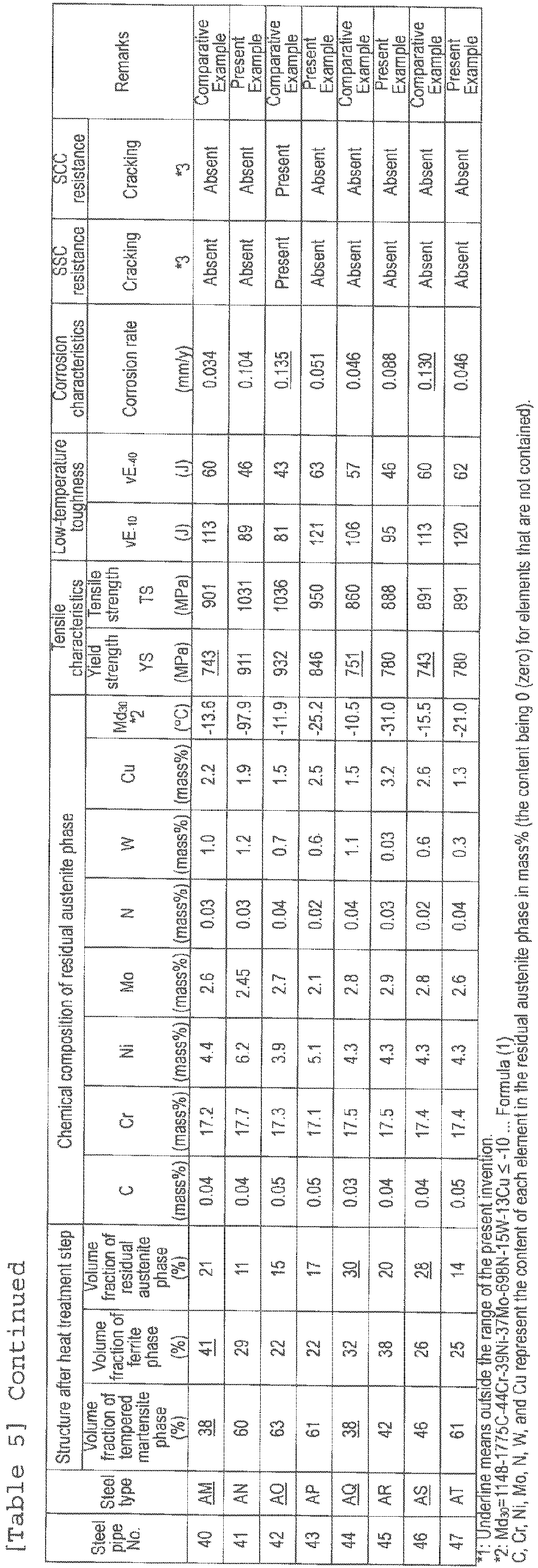


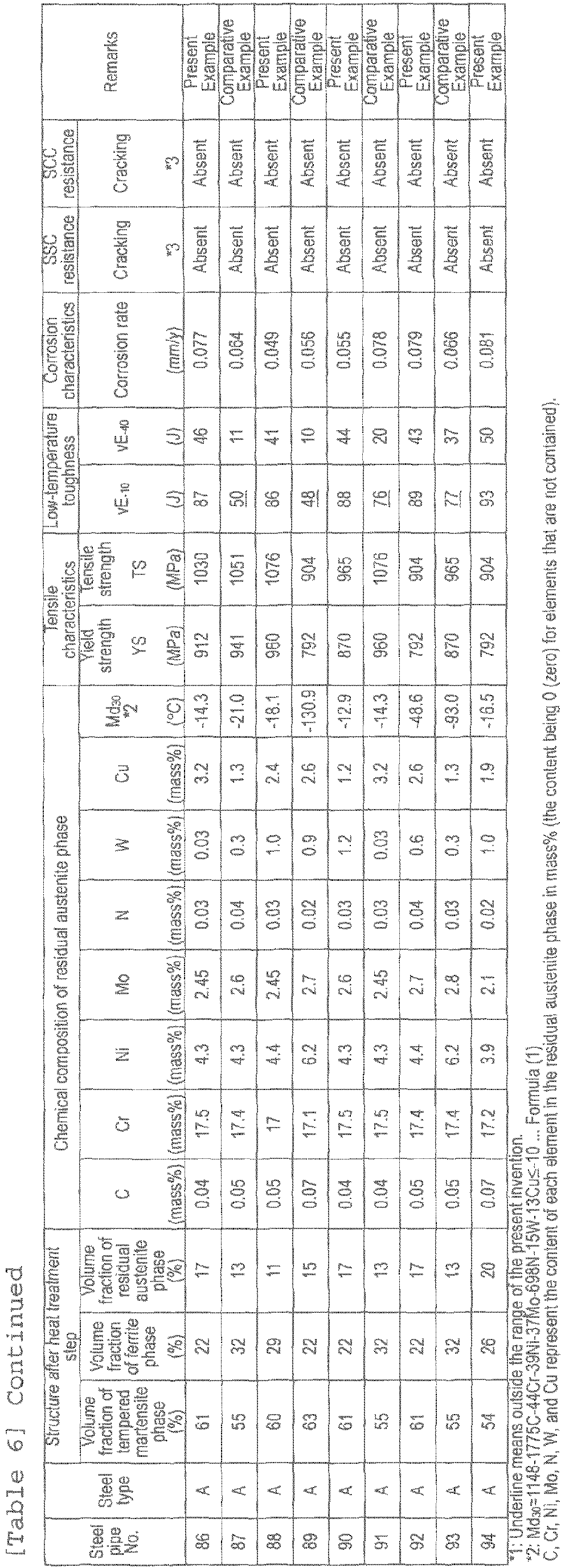
- The Present Examples all had high strength with a yield strength of 758 MPa or more, and low-temperature toughness with an absorption energy at -10°C of 80 J or more. The high strength seamless stainless steel pipes of the Present Examples also had excellent corrosion resistance (carbon dioxide corrosion resistance) in a CO2- and Cl--containing high-temperature corrosive environment of 200°C, and excellent sulfide stress cracking resistance and sulfide stress corrosion cracking resistance that did not involve cracking (SSC, SCC) in the H2S-containing environment. On the other hand, the Comparative Examples outside of the range of the present invention did not have the desired high strength, low-temperature toughness, carbon dioxide corrosion resistance, sulfide stress cracking resistance(SSC resistance), and/or sulfide stress corrosion cracking resistance (SCC resistance) of the present invention.
Claims (6)
- A high strength seamless stainless steel pipe of a composition comprising, in mass%, C : 0.012 to 0.05%, Si: 1.0% or less, Mn: 0.1 to 0.5%, P: 0.05% or less, S: 0.005% or less, Cr: more than 16.0% and 18.0% or less, Mo: more than 2.0% and 3.0% or less, Cu: 0.5 to 3.5%, Ni: 3.0% or more and less than 5.0%, W : 0.01 to 3.0%, Nb: 0.01 to 0.5%, Al: 0.001 to 0.1%, N : 0.012 to 0.07%, O : 0.01% or less, and the balance Fe and unavoidable impurities, the high strength seamless stainless steel pipe having a structure that includes a tempered martensite phase as a primary phase, and 20 to 40% ferrite phase, and at most 25% residual austenite phase in terms of a volume fraction, and in which C, Cr, Ni, Mo, N, W, and Cu in the residual austenite phase satisfy the following formula (1):

- The high strength seamless stainless steel pipe according to claim 1, wherein the composition further comprises, in mass%, at least one selected from Ti: 0.3% or less, V: 0.5% or less, Zr: 0.2% or less, Co: 1.4% or less, Ta: 0.1% or less, and B: 0.0100% or less.
- The high strength seamless stainless steel pipe according to claim 1 or 2, wherein the composition further comprises, in mass%, at least one selected from Ca: 0.0005 to 0.0050%, and REM: 0.001 to 0.01%.
- A method for producing a high strength seamless stainless steel pipe from a steel pipe material of a composition containing, in mass%, C : 0.012 to 0.05%, Si: 1.0% or less, Mn: 0.1 to 0.5%, P: 0.05% or less, S: 0.005% or less, Cr: more than 16.0% and 18.0% or less, Mo: more than 2.0% and 3.0% or less, Cu: 0.5 to 3.5%, Ni: 3.0% or more and less than 5.0%, W : 0.01 to 3.00, Nb: 0.01 to 0.5%, Al: 0.001 to 0.1%, N : 0.012 to 0.07%, O : 0.01% or less, and the balance Fe and unavoidable impurities,
the method comprising:heating the steel pipe material at a heating temperature of 1,100 to 1,300°C, and forming a seamless steel pipe of a predetermined shape by hot working;heating the seamless steel pipe to a quenching temperature of 850 to 1,1.50°C after the hot working;quenching the seamless steel pipe by cooling the seamless steel pipe at an average cooling rate of 0.05°C/s or more to a cooling stop temperature at which the seamless steel pipe has a surface temperature of 50°C or less and more than 0°C;subjecting the seamless steel pipe to an austenite stabilizing heat treatment in which the seamless steel pipe is heated to a temperature of 200 to 500°C, and air cooled; andtempering the seamless steel pipe by heating the seamless steel pipe to a tempering temperature of 500 to 650°C. - The method for producing a high strength seamless stainless steel pipe according to claim 4, wherein the composition further contains, in mass%, at least one selected from Ti: 0.3% or less, V: 0.5% or less, Zr: 0.2% or less, Co: 1.4% or less, Ta: 0.1% or less, and B: 0.0100% or less.
- The method for producing a high strength seamless stainless steel pipe according to claim 4 or 5, wherein the composition further contains, in mass%, at least one selected from Ca: 0.0005 to 0.0050%, and REM: 0.001 to 0.01%.
Applications Claiming Priority (2)
| Application Number | Priority Date | Filing Date | Title |
|---|---|---|---|
| JP2017003970 | 2017-01-13 | ||
| PCT/JP2017/043775 WO2018131340A1 (en) | 2017-01-13 | 2017-12-06 | High strength seamless stainless steel pipe and production method therefor |
Publications (3)
| Publication Number | Publication Date |
|---|---|
| EP3569724A1 true EP3569724A1 (en) | 2019-11-20 |
| EP3569724A4 EP3569724A4 (en) | 2019-12-25 |
| EP3569724B1 EP3569724B1 (en) | 2022-02-02 |
Family
ID=62840465
Family Applications (1)
| Application Number | Title | Priority Date | Filing Date |
|---|---|---|---|
| EP17890889.3A Active EP3569724B1 (en) | 2017-01-13 | 2017-12-06 | High strength seamless stainless steel pipe and production method therefor |
Country Status (7)
| Country | Link |
|---|---|
| US (1) | US11268161B2 (en) |
| EP (1) | EP3569724B1 (en) |
| JP (1) | JP6384636B1 (en) |
| AR (1) | AR110828A1 (en) |
| BR (1) | BR112019013803A2 (en) |
| MX (1) | MX2019008377A (en) |
| WO (1) | WO2018131340A1 (en) |
Cited By (6)
| Publication number | Priority date | Publication date | Assignee | Title |
|---|---|---|---|---|
| US12098438B2 (en) | 2019-03-29 | 2024-09-24 | Jfe Steel Corporation | Stainless steel seamless pipe |
| EP4123039A4 (en) * | 2020-03-19 | 2024-09-25 | JFE Steel Corporation | SEAMLESS STAINLESS STEEL PIPE AND METHOD FOR PRODUCING SEAMLESS STAINLESS STEEL PIPE |
| EP4108797A4 (en) * | 2020-04-01 | 2024-09-25 | JFE Steel Corporation | HIGH STRENGTH SEAMLESS STAINLESS STEEL PIPE FOR OIL WELL AND METHOD OF MANUFACTURING SAME |
| EP4123040A4 (en) * | 2020-03-19 | 2024-10-02 | JFE Steel Corporation | SEAMLESS STAINLESS STEEL TUBE AND METHOD FOR PRODUCING A SEAMLESS STAINLESS STEEL TUBE |
| US12291766B2 (en) | 2019-10-01 | 2025-05-06 | Jfe Steel Corporation | Stainless steel seamless pipe and method for manufacturing same |
| US12497676B2 (en) | 2019-10-01 | 2025-12-16 | Jfe Steel Corporation | Stainless steel seamless pipe and method for manufacturing same |
Families Citing this family (14)
| Publication number | Priority date | Publication date | Assignee | Title |
|---|---|---|---|---|
| MX2018000331A (en) | 2015-07-10 | 2018-03-14 | Jfe Steel Corp | High strength seamless stainless steel pipe and manufacturing method therefor. |
| MX378757B (en) * | 2016-02-08 | 2025-03-11 | Jfe Steel Corp | HIGH STRENGTH SEAMLESS STAINLESS STEEL TUBE FOR TUBULAR PRODUCTS FOR THE PETROLEUM INDUSTRY AND MANUFACTURING METHOD FOR HIGH STRENGTH SEAMLESS STAINLESS STEEL TUBE. |
| MX2018011883A (en) * | 2016-03-29 | 2018-12-17 | Jfe Steel Corp | STAINLESS STEEL PIPE WITHOUT HIGH RESISTANCE WELDING FOR TUBULAR ITEMS FOR THE PETROLEUM INDUSTRY. |
| JP6304460B1 (en) | 2016-07-27 | 2018-04-04 | Jfeスチール株式会社 | High strength stainless steel seamless steel pipe for oil well and method for producing the same |
| WO2018043310A1 (en) * | 2016-09-02 | 2018-03-08 | Jfeスチール株式会社 | Ferritic stainless steel |
| JP6418338B2 (en) | 2016-09-02 | 2018-11-07 | Jfeスチール株式会社 | Ferritic stainless steel |
| US11268161B2 (en) | 2017-01-13 | 2022-03-08 | Jfe Steel Corporation | High strength seamless stainless steel pipe and method for producing same |
| WO2018155041A1 (en) | 2017-02-24 | 2018-08-30 | Jfeスチール株式会社 | High strength seamless stainless steel pipe for oil well and production method therefor |
| CN110462079B (en) | 2017-03-30 | 2021-07-13 | 杰富意钢铁株式会社 | Ferritic stainless steel |
| CN118854188A (en) * | 2017-05-26 | 2024-10-29 | 杰富意钢铁株式会社 | Ferritic stainless steel |
| JP7226571B2 (en) * | 2020-07-06 | 2023-02-21 | Jfeスチール株式会社 | Seamless stainless steel pipe and manufacturing method thereof |
| EP4636112A1 (en) * | 2023-04-06 | 2025-10-22 | JFE Steel Corporation | Seamless stainless steel pipe and production method therefor |
| JP2025048722A (en) * | 2023-09-21 | 2025-04-03 | Jfeスチール株式会社 | Seamless steel pipe, method for drilling rolled material, and method for manufacturing seamless steel pipe |
| CN120945300A (en) * | 2025-09-22 | 2025-11-14 | 浙江大学 | A high-strength, high-toughness, low-nickel nitrogen-containing stainless steel and its preparation method |
Family Cites Families (35)
| Publication number | Priority date | Publication date | Assignee | Title |
|---|---|---|---|---|
| EP1553198A1 (en) | 2002-06-14 | 2005-07-13 | JFE Steel Corporation | Heat-resistant ferritic stainless steel and method for production thereof |
| EP1514950B1 (en) | 2002-06-19 | 2011-09-28 | JFE Steel Corporation | Stainless-steel pipe for oil well and process for producing the same |
| JP5109222B2 (en) | 2003-08-19 | 2012-12-26 | Jfeスチール株式会社 | High strength stainless steel seamless steel pipe for oil well with excellent corrosion resistance and method for producing the same |
| US7520942B2 (en) | 2004-09-22 | 2009-04-21 | Ut-Battelle, Llc | Nano-scale nitride-particle-strengthened high-temperature wrought ferritic and martensitic steels |
| JP4893196B2 (en) | 2006-09-28 | 2012-03-07 | Jfeスチール株式会社 | High strength stainless steel pipe for oil well with high toughness and excellent corrosion resistance |
| JP5211552B2 (en) | 2007-05-31 | 2013-06-12 | Jfeスチール株式会社 | Stainless steel pipe for oil well with excellent pipe expandability and method for producing the same |
| AR073884A1 (en) | 2008-10-30 | 2010-12-09 | Sumitomo Metal Ind | STAINLESS STEEL TUBE OF HIGH RESISTANCE EXCELLENT IN RESISTANCE TO FISURATION UNDER VOLTAGE SULFURS AND CORROSION OF GAS OF CARBONIC ACID IN HIGH TEMPERATURE. |
| JP5446335B2 (en) | 2009-03-10 | 2014-03-19 | Jfeスチール株式会社 | Evaluation method of high strength stainless steel pipe for oil well |
| JP5487689B2 (en) | 2009-04-06 | 2014-05-07 | Jfeスチール株式会社 | Manufacturing method of martensitic stainless steel seamless pipe for oil well pipe |
| AR076669A1 (en) | 2009-05-18 | 2011-06-29 | Sumitomo Metal Ind | STAINLESS STEEL FOR PETROLEUM WELLS, STAINLESS STEEL TUBE FOR PETROLEUM WELLS, AND STAINLESS STEEL MANUFACTURING METHOD FOR PETROLEUM WELLS |
| JP5640762B2 (en) | 2011-01-20 | 2014-12-17 | Jfeスチール株式会社 | High strength martensitic stainless steel seamless pipe for oil wells |
| CN104204253B (en) | 2012-03-26 | 2017-03-29 | 新日铁住金株式会社 | Oil well stainless steel and oil well stainless steel tube |
| JP5924256B2 (en) | 2012-06-21 | 2016-05-25 | Jfeスチール株式会社 | High strength stainless steel seamless pipe for oil well with excellent corrosion resistance and manufacturing method thereof |
| JP5967066B2 (en) | 2012-12-21 | 2016-08-10 | Jfeスチール株式会社 | High strength stainless steel seamless steel pipe for oil well with excellent corrosion resistance and method for producing the same |
| JP6075349B2 (en) | 2013-10-08 | 2017-02-08 | Jfeスチール株式会社 | Ferritic stainless steel |
| FI125466B (en) * | 2014-02-03 | 2015-10-15 | Outokumpu Oy | DUPLEX STAINLESS STEEL |
| BR102014005015A8 (en) | 2014-02-28 | 2017-12-26 | Villares Metals S/A | martensitic-ferritic stainless steel, manufactured product, process for producing forged or rolled bars or parts of martensitic-ferritic stainless steel and process for producing all seamless martensitic-ferritic stainless steel |
| JP6102798B2 (en) | 2014-02-28 | 2017-03-29 | Jfeスチール株式会社 | Manufacturing method of martensitic stainless steel pipe for line pipe excellent in reel barge laying |
| JP6137082B2 (en) * | 2014-07-31 | 2017-05-31 | Jfeスチール株式会社 | High strength stainless steel seamless steel pipe excellent in low temperature toughness and method for producing the same |
| JP6159775B2 (en) | 2014-10-31 | 2017-07-05 | 新日鐵住金ステンレス株式会社 | Ferritic stainless steel with excellent resistance to exhaust gas condensate corrosion and brazing, and method for producing the same |
| JP6315076B2 (en) * | 2014-11-18 | 2018-04-25 | Jfeスチール株式会社 | Manufacturing method of high strength stainless steel seamless steel pipe for oil well |
| JP6237873B2 (en) * | 2014-11-19 | 2017-11-29 | Jfeスチール株式会社 | High strength stainless steel seamless steel pipe for oil well |
| JP6206423B2 (en) * | 2015-01-22 | 2017-10-04 | Jfeスチール株式会社 | High strength stainless steel plate excellent in low temperature toughness and method for producing the same |
| MX2018000331A (en) | 2015-07-10 | 2018-03-14 | Jfe Steel Corp | High strength seamless stainless steel pipe and manufacturing method therefor. |
| MX378757B (en) | 2016-02-08 | 2025-03-11 | Jfe Steel Corp | HIGH STRENGTH SEAMLESS STAINLESS STEEL TUBE FOR TUBULAR PRODUCTS FOR THE PETROLEUM INDUSTRY AND MANUFACTURING METHOD FOR HIGH STRENGTH SEAMLESS STAINLESS STEEL TUBE. |
| CN109072373A (en) | 2016-03-29 | 2018-12-21 | 杰富意钢铁株式会社 | Ferrite stainless steel sheet |
| WO2017212905A1 (en) | 2016-06-10 | 2017-12-14 | Jfeスチール株式会社 | Stainless steel sheet for fuel cell separators, and production method therefor |
| CA3026612A1 (en) | 2016-06-10 | 2017-12-14 | Jfe Steel Corporation | Stainless steel sheet for fuel cell separators, and production method therefor |
| WO2018043310A1 (en) | 2016-09-02 | 2018-03-08 | Jfeスチール株式会社 | Ferritic stainless steel |
| JP6418338B2 (en) | 2016-09-02 | 2018-11-07 | Jfeスチール株式会社 | Ferritic stainless steel |
| US11268161B2 (en) | 2017-01-13 | 2022-03-08 | Jfe Steel Corporation | High strength seamless stainless steel pipe and method for producing same |
| MX2019008874A (en) | 2017-01-26 | 2019-09-18 | Jfe Steel Corp | HOT ROLLED FERRITIC STAINLESS STEEL SHEET AND METHOD FOR THE MANUFACTURE OF THE SAME. |
| WO2018155041A1 (en) | 2017-02-24 | 2018-08-30 | Jfeスチール株式会社 | High strength seamless stainless steel pipe for oil well and production method therefor |
| CN118854188A (en) | 2017-05-26 | 2024-10-29 | 杰富意钢铁株式会社 | Ferritic stainless steel |
| US11286548B2 (en) | 2017-08-15 | 2022-03-29 | Jfe Steel Corporation | High-strength stainless steel seamless pipe for oil country tubular goods, and method for manufacturing same |
-
2017
- 2017-12-06 US US16/477,393 patent/US11268161B2/en active Active
- 2017-12-06 MX MX2019008377A patent/MX2019008377A/en unknown
- 2017-12-06 BR BR112019013803-0A patent/BR112019013803A2/en not_active Application Discontinuation
- 2017-12-06 JP JP2018516099A patent/JP6384636B1/en active Active
- 2017-12-06 WO PCT/JP2017/043775 patent/WO2018131340A1/en not_active Ceased
- 2017-12-06 EP EP17890889.3A patent/EP3569724B1/en active Active
-
2018
- 2018-01-12 AR ARP180100076A patent/AR110828A1/en active IP Right Grant
Cited By (8)
| Publication number | Priority date | Publication date | Assignee | Title |
|---|---|---|---|---|
| US12098438B2 (en) | 2019-03-29 | 2024-09-24 | Jfe Steel Corporation | Stainless steel seamless pipe |
| US12291766B2 (en) | 2019-10-01 | 2025-05-06 | Jfe Steel Corporation | Stainless steel seamless pipe and method for manufacturing same |
| US12497676B2 (en) | 2019-10-01 | 2025-12-16 | Jfe Steel Corporation | Stainless steel seamless pipe and method for manufacturing same |
| EP4123039A4 (en) * | 2020-03-19 | 2024-09-25 | JFE Steel Corporation | SEAMLESS STAINLESS STEEL PIPE AND METHOD FOR PRODUCING SEAMLESS STAINLESS STEEL PIPE |
| EP4123040A4 (en) * | 2020-03-19 | 2024-10-02 | JFE Steel Corporation | SEAMLESS STAINLESS STEEL TUBE AND METHOD FOR PRODUCING A SEAMLESS STAINLESS STEEL TUBE |
| US12497670B2 (en) | 2020-03-19 | 2025-12-16 | Jfe Steel Corporation | Stainless steel seamless pipe and method for manufacturing stainless steel seamless pipe |
| US12577631B2 (en) | 2020-03-19 | 2026-03-17 | Jfe Steel Corporation | Stainless steel seamless pipe and method for manufacturing stainless steel seamless pipe |
| EP4108797A4 (en) * | 2020-04-01 | 2024-09-25 | JFE Steel Corporation | HIGH STRENGTH SEAMLESS STAINLESS STEEL PIPE FOR OIL WELL AND METHOD OF MANUFACTURING SAME |
Also Published As
| Publication number | Publication date |
|---|---|
| US20190368001A1 (en) | 2019-12-05 |
| WO2018131340A1 (en) | 2018-07-19 |
| AR110828A1 (en) | 2019-05-08 |
| US11268161B2 (en) | 2022-03-08 |
| JP6384636B1 (en) | 2018-09-05 |
| BR112019013803A2 (en) | 2020-01-21 |
| MX2019008377A (en) | 2019-09-16 |
| JPWO2018131340A1 (en) | 2019-01-17 |
| EP3569724A4 (en) | 2019-12-25 |
| EP3569724B1 (en) | 2022-02-02 |
Similar Documents
| Publication | Publication Date | Title |
|---|---|---|
| EP3569724B1 (en) | High strength seamless stainless steel pipe and production method therefor | |
| EP3670693B1 (en) | High-strength stainless steel seamless pipe for oil country tubular goods, and method for manufacturing same | |
| EP3561131B1 (en) | High strength seamless stainless steel pipe for oil well and production method therefor | |
| EP3508596B1 (en) | Dual-phase stainless seamless steel pipe and method of production thereof | |
| US10876183B2 (en) | High-strength seamless stainless steel pipe and method of manufacturing high-strength seamless stainless steel pipe | |
| RU2698233C1 (en) | High-strength seamless stainless steel pipe for oil-field range tubular goods and method of its production | |
| EP3604591A1 (en) | Martensitic stainless steel material | |
| US12497676B2 (en) | Stainless steel seamless pipe and method for manufacturing same | |
| US12497670B2 (en) | Stainless steel seamless pipe and method for manufacturing stainless steel seamless pipe | |
| EP3569725B1 (en) | Duplex stainless steel and method for producing same | |
| EP4123040A1 (en) | Stainless seamless steel pipe and method for producing stainless seamless steel pipe | |
| EP3916120B1 (en) | Stainless steel seamless pipe | |
| EP4108797A1 (en) | High-strength stainless steel seamless pipe for oil well, and method for producing same | |
| EP4234725A1 (en) | High-strength stainless steel seamless pipe for oil well, and method for producing same | |
| EP3805420A1 (en) | Martensitic stainless steel seamless steel tube for oil well pipes, and method for producing same | |
| EP4509630A1 (en) | Seamless stainless steel pipe and production method therefor | |
| JP7226571B2 (en) | Seamless stainless steel pipe and manufacturing method thereof | |
| EP3733890A1 (en) | Low alloy high strength seamless steel pipe for oil wells | |
| EP4012053A1 (en) | Seamless stainless steel pipe and method for manufacturing same | |
| EP3978641A1 (en) | Duplex stainless steel and method for manufacturing same, and duplex stainless steel pipe | |
| EP4509629A1 (en) | Seamless stainless steel pipe and method for manufacturing same | |
| EP4414463A1 (en) | High-strength seamless stainless steel pipe for oil wells |
Legal Events
| Date | Code | Title | Description |
|---|---|---|---|
| STAA | Information on the status of an ep patent application or granted ep patent |
Free format text: STATUS: THE INTERNATIONAL PUBLICATION HAS BEEN MADE |
|
| PUAI | Public reference made under article 153(3) epc to a published international application that has entered the european phase |
Free format text: ORIGINAL CODE: 0009012 |
|
| STAA | Information on the status of an ep patent application or granted ep patent |
Free format text: STATUS: REQUEST FOR EXAMINATION WAS MADE |
|
| 17P | Request for examination filed |
Effective date: 20190711 |
|
| AK | Designated contracting states |
Kind code of ref document: A1 Designated state(s): AL AT BE BG CH CY CZ DE DK EE ES FI FR GB GR HR HU IE IS IT LI LT LU LV MC MK MT NL NO PL PT RO RS SE SI SK SM TR |
|
| AX | Request for extension of the european patent |
Extension state: BA ME |
|
| A4 | Supplementary search report drawn up and despatched |
Effective date: 20191126 |
|
| RIC1 | Information provided on ipc code assigned before grant |
Ipc: C21D 9/08 20060101ALI20191120BHEP Ipc: C22C 38/06 20060101ALI20191120BHEP Ipc: C22C 38/42 20060101ALI20191120BHEP Ipc: C22C 38/04 20060101ALI20191120BHEP Ipc: C21D 8/10 20060101ALI20191120BHEP Ipc: C22C 38/46 20060101ALI20191120BHEP Ipc: C22C 38/50 20060101ALI20191120BHEP Ipc: C22C 38/52 20060101ALI20191120BHEP Ipc: C22C 38/02 20060101ALI20191120BHEP Ipc: C22C 38/54 20060101ALI20191120BHEP Ipc: C22C 38/00 20060101AFI20191120BHEP Ipc: C21D 1/22 20060101ALI20191120BHEP Ipc: C21D 6/00 20060101ALI20191120BHEP Ipc: C22C 38/44 20060101ALI20191120BHEP Ipc: C22C 38/48 20060101ALI20191120BHEP |
|
| DAV | Request for validation of the european patent (deleted) | ||
| DAX | Request for extension of the european patent (deleted) | ||
| STAA | Information on the status of an ep patent application or granted ep patent |
Free format text: STATUS: EXAMINATION IS IN PROGRESS |
|
| 17Q | First examination report despatched |
Effective date: 20210128 |
|
| GRAP | Despatch of communication of intention to grant a patent |
Free format text: ORIGINAL CODE: EPIDOSNIGR1 |
|
| STAA | Information on the status of an ep patent application or granted ep patent |
Free format text: STATUS: GRANT OF PATENT IS INTENDED |
|
| INTG | Intention to grant announced |
Effective date: 20210803 |
|
| GRAS | Grant fee paid |
Free format text: ORIGINAL CODE: EPIDOSNIGR3 |
|
| GRAA | (expected) grant |
Free format text: ORIGINAL CODE: 0009210 |
|
| STAA | Information on the status of an ep patent application or granted ep patent |
Free format text: STATUS: THE PATENT HAS BEEN GRANTED |
|
| AK | Designated contracting states |
Kind code of ref document: B1 Designated state(s): AL AT BE BG CH CY CZ DE DK EE ES FI FR GB GR HR HU IE IS IT LI LT LU LV MC MK MT NL NO PL PT RO RS SE SI SK SM TR |
|
| REG | Reference to a national code |
Ref country code: GB Ref legal event code: FG4D |
|
| REG | Reference to a national code |
Ref country code: CH Ref legal event code: EP Ref country code: AT Ref legal event code: REF Ref document number: 1466607 Country of ref document: AT Kind code of ref document: T Effective date: 20220215 |
|
| REG | Reference to a national code |
Ref country code: DE Ref legal event code: R096 Ref document number: 602017053065 Country of ref document: DE |
|
| REG | Reference to a national code |
Ref country code: IE Ref legal event code: FG4D |
|
| REG | Reference to a national code |
Ref country code: LT Ref legal event code: MG9D |
|
| REG | Reference to a national code |
Ref country code: NL Ref legal event code: MP Effective date: 20220202 |
|
| REG | Reference to a national code |
Ref country code: AT Ref legal event code: MK05 Ref document number: 1466607 Country of ref document: AT Kind code of ref document: T Effective date: 20220202 |
|
| PG25 | Lapsed in a contracting state [announced via postgrant information from national office to epo] |
Ref country code: SE Free format text: LAPSE BECAUSE OF FAILURE TO SUBMIT A TRANSLATION OF THE DESCRIPTION OR TO PAY THE FEE WITHIN THE PRESCRIBED TIME-LIMIT Effective date: 20220202 Ref country code: RS Free format text: LAPSE BECAUSE OF FAILURE TO SUBMIT A TRANSLATION OF THE DESCRIPTION OR TO PAY THE FEE WITHIN THE PRESCRIBED TIME-LIMIT Effective date: 20220202 Ref country code: PT Free format text: LAPSE BECAUSE OF FAILURE TO SUBMIT A TRANSLATION OF THE DESCRIPTION OR TO PAY THE FEE WITHIN THE PRESCRIBED TIME-LIMIT Effective date: 20220602 Ref country code: NO Free format text: LAPSE BECAUSE OF FAILURE TO SUBMIT A TRANSLATION OF THE DESCRIPTION OR TO PAY THE FEE WITHIN THE PRESCRIBED TIME-LIMIT Effective date: 20220502 Ref country code: NL Free format text: LAPSE BECAUSE OF FAILURE TO SUBMIT A TRANSLATION OF THE DESCRIPTION OR TO PAY THE FEE WITHIN THE PRESCRIBED TIME-LIMIT Effective date: 20220202 Ref country code: LT Free format text: LAPSE BECAUSE OF FAILURE TO SUBMIT A TRANSLATION OF THE DESCRIPTION OR TO PAY THE FEE WITHIN THE PRESCRIBED TIME-LIMIT Effective date: 20220202 Ref country code: HR Free format text: LAPSE BECAUSE OF FAILURE TO SUBMIT A TRANSLATION OF THE DESCRIPTION OR TO PAY THE FEE WITHIN THE PRESCRIBED TIME-LIMIT Effective date: 20220202 Ref country code: ES Free format text: LAPSE BECAUSE OF FAILURE TO SUBMIT A TRANSLATION OF THE DESCRIPTION OR TO PAY THE FEE WITHIN THE PRESCRIBED TIME-LIMIT Effective date: 20220202 Ref country code: BG Free format text: LAPSE BECAUSE OF FAILURE TO SUBMIT A TRANSLATION OF THE DESCRIPTION OR TO PAY THE FEE WITHIN THE PRESCRIBED TIME-LIMIT Effective date: 20220502 |
|
| PG25 | Lapsed in a contracting state [announced via postgrant information from national office to epo] |
Ref country code: PL Free format text: LAPSE BECAUSE OF FAILURE TO SUBMIT A TRANSLATION OF THE DESCRIPTION OR TO PAY THE FEE WITHIN THE PRESCRIBED TIME-LIMIT Effective date: 20220202 Ref country code: LV Free format text: LAPSE BECAUSE OF FAILURE TO SUBMIT A TRANSLATION OF THE DESCRIPTION OR TO PAY THE FEE WITHIN THE PRESCRIBED TIME-LIMIT Effective date: 20220202 Ref country code: GR Free format text: LAPSE BECAUSE OF FAILURE TO SUBMIT A TRANSLATION OF THE DESCRIPTION OR TO PAY THE FEE WITHIN THE PRESCRIBED TIME-LIMIT Effective date: 20220503 Ref country code: FI Free format text: LAPSE BECAUSE OF FAILURE TO SUBMIT A TRANSLATION OF THE DESCRIPTION OR TO PAY THE FEE WITHIN THE PRESCRIBED TIME-LIMIT Effective date: 20220202 Ref country code: AT Free format text: LAPSE BECAUSE OF FAILURE TO SUBMIT A TRANSLATION OF THE DESCRIPTION OR TO PAY THE FEE WITHIN THE PRESCRIBED TIME-LIMIT Effective date: 20220202 |
|
| PG25 | Lapsed in a contracting state [announced via postgrant information from national office to epo] |
Ref country code: IS Free format text: LAPSE BECAUSE OF FAILURE TO SUBMIT A TRANSLATION OF THE DESCRIPTION OR TO PAY THE FEE WITHIN THE PRESCRIBED TIME-LIMIT Effective date: 20220602 |
|
| PG25 | Lapsed in a contracting state [announced via postgrant information from national office to epo] |
Ref country code: SM Free format text: LAPSE BECAUSE OF FAILURE TO SUBMIT A TRANSLATION OF THE DESCRIPTION OR TO PAY THE FEE WITHIN THE PRESCRIBED TIME-LIMIT Effective date: 20220202 Ref country code: SK Free format text: LAPSE BECAUSE OF FAILURE TO SUBMIT A TRANSLATION OF THE DESCRIPTION OR TO PAY THE FEE WITHIN THE PRESCRIBED TIME-LIMIT Effective date: 20220202 Ref country code: RO Free format text: LAPSE BECAUSE OF FAILURE TO SUBMIT A TRANSLATION OF THE DESCRIPTION OR TO PAY THE FEE WITHIN THE PRESCRIBED TIME-LIMIT Effective date: 20220202 Ref country code: EE Free format text: LAPSE BECAUSE OF FAILURE TO SUBMIT A TRANSLATION OF THE DESCRIPTION OR TO PAY THE FEE WITHIN THE PRESCRIBED TIME-LIMIT Effective date: 20220202 Ref country code: DK Free format text: LAPSE BECAUSE OF FAILURE TO SUBMIT A TRANSLATION OF THE DESCRIPTION OR TO PAY THE FEE WITHIN THE PRESCRIBED TIME-LIMIT Effective date: 20220202 Ref country code: CZ Free format text: LAPSE BECAUSE OF FAILURE TO SUBMIT A TRANSLATION OF THE DESCRIPTION OR TO PAY THE FEE WITHIN THE PRESCRIBED TIME-LIMIT Effective date: 20220202 |
|
| REG | Reference to a national code |
Ref country code: DE Ref legal event code: R097 Ref document number: 602017053065 Country of ref document: DE |
|
| PG25 | Lapsed in a contracting state [announced via postgrant information from national office to epo] |
Ref country code: AL Free format text: LAPSE BECAUSE OF FAILURE TO SUBMIT A TRANSLATION OF THE DESCRIPTION OR TO PAY THE FEE WITHIN THE PRESCRIBED TIME-LIMIT Effective date: 20220202 |
|
| PLBE | No opposition filed within time limit |
Free format text: ORIGINAL CODE: 0009261 |
|
| STAA | Information on the status of an ep patent application or granted ep patent |
Free format text: STATUS: NO OPPOSITION FILED WITHIN TIME LIMIT |
|
| 26N | No opposition filed |
Effective date: 20221103 |
|
| PG25 | Lapsed in a contracting state [announced via postgrant information from national office to epo] |
Ref country code: SI Free format text: LAPSE BECAUSE OF FAILURE TO SUBMIT A TRANSLATION OF THE DESCRIPTION OR TO PAY THE FEE WITHIN THE PRESCRIBED TIME-LIMIT Effective date: 20220202 |
|
| REG | Reference to a national code |
Ref country code: CH Ref legal event code: PL |
|
| GBPC | Gb: european patent ceased through non-payment of renewal fee |
Effective date: 20221206 |
|
| REG | Reference to a national code |
Ref country code: BE Ref legal event code: MM Effective date: 20221231 |
|
| PG25 | Lapsed in a contracting state [announced via postgrant information from national office to epo] |
Ref country code: LU Free format text: LAPSE BECAUSE OF NON-PAYMENT OF DUE FEES Effective date: 20221206 |
|
| PG25 | Lapsed in a contracting state [announced via postgrant information from national office to epo] |
Ref country code: LI Free format text: LAPSE BECAUSE OF NON-PAYMENT OF DUE FEES Effective date: 20221231 Ref country code: IE Free format text: LAPSE BECAUSE OF NON-PAYMENT OF DUE FEES Effective date: 20221206 Ref country code: GB Free format text: LAPSE BECAUSE OF NON-PAYMENT OF DUE FEES Effective date: 20221206 Ref country code: CH Free format text: LAPSE BECAUSE OF NON-PAYMENT OF DUE FEES Effective date: 20221231 |
|
| PG25 | Lapsed in a contracting state [announced via postgrant information from national office to epo] |
Ref country code: BE Free format text: LAPSE BECAUSE OF NON-PAYMENT OF DUE FEES Effective date: 20221231 |
|
| PGFP | Annual fee paid to national office [announced via postgrant information from national office to epo] |
Ref country code: FR Payment date: 20231108 Year of fee payment: 7 Ref country code: DE Payment date: 20231031 Year of fee payment: 7 |
|
| PG25 | Lapsed in a contracting state [announced via postgrant information from national office to epo] |
Ref country code: HU Free format text: LAPSE BECAUSE OF FAILURE TO SUBMIT A TRANSLATION OF THE DESCRIPTION OR TO PAY THE FEE WITHIN THE PRESCRIBED TIME-LIMIT; INVALID AB INITIO Effective date: 20171206 |
|
| PG25 | Lapsed in a contracting state [announced via postgrant information from national office to epo] |
Ref country code: CY Free format text: LAPSE BECAUSE OF FAILURE TO SUBMIT A TRANSLATION OF THE DESCRIPTION OR TO PAY THE FEE WITHIN THE PRESCRIBED TIME-LIMIT Effective date: 20220202 |
|
| PG25 | Lapsed in a contracting state [announced via postgrant information from national office to epo] |
Ref country code: MK Free format text: LAPSE BECAUSE OF FAILURE TO SUBMIT A TRANSLATION OF THE DESCRIPTION OR TO PAY THE FEE WITHIN THE PRESCRIBED TIME-LIMIT Effective date: 20220202 |
|
| PG25 | Lapsed in a contracting state [announced via postgrant information from national office to epo] |
Ref country code: MC Free format text: LAPSE BECAUSE OF FAILURE TO SUBMIT A TRANSLATION OF THE DESCRIPTION OR TO PAY THE FEE WITHIN THE PRESCRIBED TIME-LIMIT Effective date: 20220202 |
|
| PG25 | Lapsed in a contracting state [announced via postgrant information from national office to epo] |
Ref country code: TR Free format text: LAPSE BECAUSE OF FAILURE TO SUBMIT A TRANSLATION OF THE DESCRIPTION OR TO PAY THE FEE WITHIN THE PRESCRIBED TIME-LIMIT Effective date: 20220202 Ref country code: MC Free format text: LAPSE BECAUSE OF FAILURE TO SUBMIT A TRANSLATION OF THE DESCRIPTION OR TO PAY THE FEE WITHIN THE PRESCRIBED TIME-LIMIT Effective date: 20220202 |
|
| PG25 | Lapsed in a contracting state [announced via postgrant information from national office to epo] |
Ref country code: MT Free format text: LAPSE BECAUSE OF FAILURE TO SUBMIT A TRANSLATION OF THE DESCRIPTION OR TO PAY THE FEE WITHIN THE PRESCRIBED TIME-LIMIT Effective date: 20220202 |
|
| REG | Reference to a national code |
Ref country code: DE Ref legal event code: R119 Ref document number: 602017053065 Country of ref document: DE |
|
| PG25 | Lapsed in a contracting state [announced via postgrant information from national office to epo] |
Ref country code: DE Free format text: LAPSE BECAUSE OF NON-PAYMENT OF DUE FEES Effective date: 20250701 |
|
| PG25 | Lapsed in a contracting state [announced via postgrant information from national office to epo] |
Ref country code: FR Free format text: LAPSE BECAUSE OF NON-PAYMENT OF DUE FEES Effective date: 20241231 |
|
| PGFP | Annual fee paid to national office [announced via postgrant information from national office to epo] |
Ref country code: IT Payment date: 20251121 Year of fee payment: 9 |