EP3569494A1 - Rumpfstruktur für ein luftfahrzeug - Google Patents
Rumpfstruktur für ein luftfahrzeug Download PDFInfo
- Publication number
- EP3569494A1 EP3569494A1 EP19172960.7A EP19172960A EP3569494A1 EP 3569494 A1 EP3569494 A1 EP 3569494A1 EP 19172960 A EP19172960 A EP 19172960A EP 3569494 A1 EP3569494 A1 EP 3569494A1
- Authority
- EP
- European Patent Office
- Prior art keywords
- stiffening
- circumferential direction
- outer shell
- connection section
- fuselage
- Prior art date
- Legal status (The legal status is an assumption and is not a legal conclusion. Google has not performed a legal analysis and makes no representation as to the accuracy of the status listed.)
- Granted
Links
Images


Classifications
-
- B—PERFORMING OPERATIONS; TRANSPORTING
- B64—AIRCRAFT; AVIATION; COSMONAUTICS
- B64C—AEROPLANES; HELICOPTERS
- B64C1/00—Fuselages; Constructional features common to fuselages, wings, stabilising surfaces or the like
- B64C1/06—Frames; Stringers; Longerons ; Fuselage sections
- B64C1/061—Frames
-
- B—PERFORMING OPERATIONS; TRANSPORTING
- B64—AIRCRAFT; AVIATION; COSMONAUTICS
- B64C—AEROPLANES; HELICOPTERS
- B64C1/00—Fuselages; Constructional features common to fuselages, wings, stabilising surfaces or the like
- B64C1/06—Frames; Stringers; Longerons ; Fuselage sections
- B64C1/064—Stringers; Longerons
-
- B—PERFORMING OPERATIONS; TRANSPORTING
- B64—AIRCRAFT; AVIATION; COSMONAUTICS
- B64C—AEROPLANES; HELICOPTERS
- B64C1/00—Fuselages; Constructional features common to fuselages, wings, stabilising surfaces or the like
- B64C1/06—Frames; Stringers; Longerons ; Fuselage sections
- B64C1/068—Fuselage sections
-
- B—PERFORMING OPERATIONS; TRANSPORTING
- B64—AIRCRAFT; AVIATION; COSMONAUTICS
- B64C—AEROPLANES; HELICOPTERS
- B64C1/00—Fuselages; Constructional features common to fuselages, wings, stabilising surfaces or the like
- B64C1/06—Frames; Stringers; Longerons ; Fuselage sections
- B64C1/12—Construction or attachment of skin panels
-
- B—PERFORMING OPERATIONS; TRANSPORTING
- B64—AIRCRAFT; AVIATION; COSMONAUTICS
- B64C—AEROPLANES; HELICOPTERS
- B64C1/00—Fuselages; Constructional features common to fuselages, wings, stabilising surfaces or the like
- B64C1/40—Sound or heat insulation, e.g. using insulation blankets
- B64C1/403—Arrangement of fasteners specially adapted therefor, e.g. of clips
- B64C1/406—Arrangement of fasteners specially adapted therefor, e.g. of clips in combination with supports for lines, e.g. for pipes or cables
-
- B—PERFORMING OPERATIONS; TRANSPORTING
- B64—AIRCRAFT; AVIATION; COSMONAUTICS
- B64C—AEROPLANES; HELICOPTERS
- B64C1/00—Fuselages; Constructional features common to fuselages, wings, stabilising surfaces or the like
- B64C2001/0054—Fuselage structures substantially made from particular materials
- B64C2001/0072—Fuselage structures substantially made from particular materials from composite materials
-
- Y—GENERAL TAGGING OF NEW TECHNOLOGICAL DEVELOPMENTS; GENERAL TAGGING OF CROSS-SECTIONAL TECHNOLOGIES SPANNING OVER SEVERAL SECTIONS OF THE IPC; TECHNICAL SUBJECTS COVERED BY FORMER USPC CROSS-REFERENCE ART COLLECTIONS [XRACs] AND DIGESTS
- Y02—TECHNOLOGIES OR APPLICATIONS FOR MITIGATION OR ADAPTATION AGAINST CLIMATE CHANGE
- Y02T—CLIMATE CHANGE MITIGATION TECHNOLOGIES RELATED TO TRANSPORTATION
- Y02T50/00—Aeronautics or air transport
- Y02T50/40—Weight reduction
Definitions
- the present invention relates to a fuselage structure for an aircraft and an aircraft.
- Fuselage structures for aircraft are usually composed of longitudinal members running in a longitudinal direction, so-called stringers, and circumferential, circumferential members, so-called frames, running in a circumferential direction.
- An outer skin of the aircraft is typically fastened to this basic structure defining an interior of the aircraft.
- interior cabin components such as floors, cabin monuments and the like are arranged and connected to the fuselage structure.
- the EP 2 985 232 A1 describes a fuselage structure with ribs and stringers, which are covered by interior trim parts. A in a longitudinal direction extending air tube is arranged in a ceiling area and is integrated into the interior trim parts.
- a fuselage structure for an aircraft has a frame structure extending in a circumferential direction with a first connection section and a second connection section arranged along the circumferential direction at a distance from the first connection section.
- the frame structure can thus be designed in particular as an annular carrier or frame, wherein this has an interruption or recess between the first and the second connection section.
- the fuselage structure according to the invention furthermore has a stiffening structure extending between the first and the second connection section of the frame structure along the circumferential direction and connected in each case to the first and the second connection section.
- the stiffening structure is thus inserted into the recess of the frame structure or continues the frame structure, whereby the frame structure and the stiffening structure together form a closed frame.
- An outer shell such as an outer skin segment, is secured to an outer side of the stiffening structure, and an inner shell is secured to an inner side of the stiffening structure opposite to the outer side.
- the stiffening structure is thus arranged and connected with respect to a radial direction between the inner shell and the outer shell.
- the inner shell, the outer shell and the stiffening structure thus form a sandwich-like structure.
- the inner shell and the outer shell may also be referred to as inner trunk skin and outer trunk skin. Due to the direct attachment of the inner and the outer shell to the stiffening structure, the sandwich-type structure advantageously has a high mechanical strength.
- the stiffening structure seen in a direction transverse to the circumferential direction longitudinal direction has a profiled cross-section and forms together with the inner shell and the outer shell a plurality of circumferentially adjacent channels, each extending in the longitudinal direction.
- the stiffening structure is therefore designed, in particular, as a planar component which extends both in the circumferential direction and transversely to the circumferential direction in the longitudinal direction.
- a section in the circumferential direction or transversely to the longitudinal direction through the stiffening structure results in a cross-sectional profile, which seen increases seen in the longitudinal direction and depressions or has an undulating course.
- These longitudinal ridges and depressions, together with the inner shell and the outer shell define channel cross-sections of longitudinally extending channels.
- the channels formed in this way can be used, in particular, as air conditioning ducts or in general for accommodating functional components.
- the stiffening structure is arranged between the connection sections of the frame structure, an extremely space-saving construction results.
- the channels can be integrated directly into the fuselage structure itself and it can be dispensed with attaching the channels as additional components to the fuselage structure.
- the sandwich structure with the stiffening structure disposed between the inner and outer shells also improves the mechanical strength of the hull structure.
- the stiffening structure is profiled such that it is alternately connected to the outer shell and the inner shell along the circumferential direction.
- the stiffening structure which is preferably designed as a one-piece planar layer with an approximately constant thickness, can thus have a wave-like cross-sectional profile along the circumferential direction, for example in the form of a sine wave, a sawtooth wave, a triangular wave, a rectangular wave or a trapezoidal wave.
- a periodic cross-sectional profile is advantageous.
- a bending and in particular a shear stiffness of the fuselage structure in the circumferential direction is further improved.
- a bulge-resistant stiffening of the outer and inner shell is achieved in this way.
- the stiffening structure which may also be referred to as a reinforcing layer, alternately abuts or contacts the outer shell and the inner shell. This makes the construction even more compact and facilitates a direct transfer of force between the shells and the stiffening structure.
- the outer shell, the inner shell and the stiffening structure are each formed from a fiber composite material.
- Fiber composite materials offer the advantage that they have a high mechanical strength in relation to their weight. Fiber composite material also has the advantage that it is corrosion-resistant and fatigue-resistant, so that a corresponding inspection can be dispensed with. This is particularly advantageous because the channels formed in the interior of the fuselage structure by the reinforcing layer and the shells are difficult to access from the outside.
- the outer shell, the inner shell and the stiffening structure may each be formed of the same fiber composite material. This facilitates in particular the production of the hull structure.
- the frame structure can be formed from a fiber composite material, in particular the same fiber composite material as the stiffening structure.
- the outer shell and the inner shell are respectively connected to the stiffening structure in a material-locking manner and / or by means of fastening devices.
- a cohesive connection can be realized for example by gluing the stiffening structure with the shells. It is also conceivable to weld the shells to the stiffening structure. If the shells and the stiffening structure are formed from a fiber composite material, this can be achieved for example by an ultrasound or thermal welding process done. Alternatively or additionally or partially, a connection can also be realized by fastening devices, such as rivets, bolts, screws, clips or the like.
- the stiffening structure has a first attachment structure, which is connected to the first connection section of the frame structure, and a second attachment structure, which is connected to the second connection section of the frame structure. Accordingly, therefore, special connections are provided on opposite in relation to the circumferential direction end portions of the stiffening structure, which are formed for connection to the terminal portions of the frame structure.
- the first attachment structure and / or the second attachment structure may in particular be formed by a receiving recess formed on a projection, in which the respective connection section of the frame structure is accommodated. Accordingly, a jaw with a recess or groove is provided on the stiffening structure, in which the respective connection portion is inserted.
- the recess has a cross-sectional shape complementary to the respective connection section of the frame structure.
- the first attachment structure and / or the second attachment structure may also be formed by a profile carrier extending in the circumferential direction, which is connected to the respective connection section of the frame structure.
- the attachment structure is for example by a plate-shaped formed portion projecting from the stiffening structure in the circumferential direction.
- the profile carrier overlaps with the respective connection section of the frame structure in the circumferential direction.
- the torsional stiffness of the fuselage structure is further improved by the overlap.
- connection sections of the frame structure are respectively connected to the stiffening structure in a material-locking manner and / or by means of fastening devices.
- a cohesive connection can be realized for example by gluing or welding.
- a connection can also be made by fastening devices, such as e.g. Rivets, bolts, screws, clips or the like can be realized.
- the outer shell has an insulating layer on an inner surface facing the stiffening structure.
- the insulating layer may be formed, for example, from a mineral wool. The achieved by means of the insulating thermal insulation effect is particularly advantageous for the use of one or more of the channels as a climate channel, as this reduces the cost of a lining of the channel.
- electrical conductor tracks are formed on the inner surface of the outer shell facing the stiffening structure and / or on an inner surface of the inner shell facing the stiffening structure. Accordingly, the electrically conductive material of the conductor tracks is applied directly to the respective shell, optionally on an electrically insulating region or on an insulating layer. This saves further space for the wiring.
- functional components in particular supply lines, such as electrical or hydraulic supply lines, are arranged in the channels.
- the fuselage structure additionally has a further frame structure which is spaced apart in the longitudinal direction relative to the frame structure and has a first connection section and a second connection section arranged along the circumferential direction at a distance from the first connection section.
- the stiffening structure extends between the first and the second connection portion of the further frame structure along the circumferential direction and is connected in each case to the first and the second connection portion of the further frame structure.
- an aircraft with a fuselage structure according to one of the embodiments described above is provided.
- this may be a passenger aircraft.
- the outer shell of the fuselage structure preferably forms part of an outer skin of the aircraft.
- direction indications and axes in particular to directions and axes which relate to the course of physical structures, herein is understood to mean a course of an axis, a direction or a structure "along" another axis, direction or structure, that these, in particular the tangents resulting in a respective location of the structures, respectively, in an angle of less than or equal to 45 degrees, preferably less than or equal to 30 degrees, and more preferably parallel to each other.
- a progression of an axis, a direction or a structure is understood to be "transverse" to another axis, direction or structure, that in particular, the tangents resulting in a respective position of the structures each extend at an angle of greater than 45 degrees, preferably greater than 60 degrees, and particularly preferably perpendicular to one another.
- the fibrous material which is formed from a variety of particular filamentary or thread-like reinforcing fibers, such as carbon, glass, ceramic, aramid, boron, mineral, natural or synthetic fibers or mixtures thereof.
- the fibrous material may also be coated with a resin or matrix material such as e.g. a thermosetting, thermoplastic, elastomeric resin or generally a plastic resin or the like may be impregnated.
- Fig. 1 shows an aircraft 100 in a plan view.
- the aircraft has a hull 101 extending in a longitudinal direction L, wings 102, a tailplane 103 and a tailplane 104.
- the hull 101 has an in Fig. 1 only schematically illustrated fuselage structure 1 with multiple frames 2, 20 and an outer skin 105.
- a partial area of the outer skin 105 is formed by at least one outer shell 4 of the fuselage structure 1.
- Fig. 1 is exemplified that a plurality of along the longitudinal direction L successively arranged outer shells 4 is provided, which form a portion of the outer skin 105.
- Fig. 2 shows by way of example and schematically a sectional view of the fuselage structure 1.
- Fig. 3 is shown a partial perspective sectional view of the hull 101, which has the hull structure 1.
- the fuselage structure 1 has a first frame structure 2, one or more optional second frame structures 20, a stiffening structure or reinforcement layer 3, an outer shell 4 and an inner shell 5.
- the first frame structure 2 will be explained in more detail below. However, the statements equally apply to the optional further bulkhead structures 20.
- the first bulkhead structure 2 and the optional second bulkhead structure 20 are arranged in the longitudinal direction L at a distance from one another.
- the bulkhead structures 2, 20 may be formed in particular as ring segments.
- the bulkhead structures 2, 20 extend in a circumferential direction U and thus at least partially surround a longitudinal axis L100 of the aircraft, which extends along the longitudinal direction L.
- the circumferential direction U and the longitudinal direction L extend transversely to each other.
- the frame structure 2 for example, by a single profile carrier or by several in Circumferentially be joined together adjacent profile carrier segments.
- the frame structure 2 may for example have a Z-shaped or similar cross-section.
- the frame structure 2 has a first connection section 21 and a second connection section 22.
- the connection sections 21, 22 are provided for fastening the stiffening structure 3 and form in each case one end of the frame structure 2 with respect to the circumferential direction U.
- the first and the second connection sections 21, 22 are arranged spaced from one another along the circumferential direction U.
- the connection sections 21, 22 of the frame structure 2 thereby delimit an opening or interruption O of the frame structure 2.
- the stiffening structure 3 is disposed between the outer shell 4 and the inner shell 5 with respect to a radial direction R which extends transversely to the circumferential direction U and transverse to the longitudinal direction L.
- the outer and inner shells 4, 5 are realized in each case as components extending flat along the longitudinal direction L and along the circumferential direction U, in particular as curved plates extending along one another.
- the shells 4, 5 are optionally each formed from a fiber composite material.
- the stiffening structure 3 is realized as a layer or layer extending flat in the longitudinal direction L and the circumferential direction U, and has a profiled cross-section as seen in the longitudinal direction L.
- the stiffening structure 3 may form a zigzag, in particular triangles Have cross-sectional profile along the circumferential direction U, as exemplified in Fig. 4 is shown.
- Fig. 5 shows by way of example a trapezoidal cross-sectional profile along the circumferential direction U.
- a cross-sectional profile along the circumferential direction U may be provided which is approximately sine wave-shaped.
- the stiffening structure 3 may in particular be formed from a fiber composite material.
- the stiffening structure 3 and the shells 4, 5 are formed from the same fiber composite material.
- the stiffening structure 3 with respect to the radial direction R between the outer and the inner shell 4, 5 is arranged.
- the outer shell 4 is thus arranged on an outer side 3A of the stiffening structure 3 and in particular attached thereto.
- the inner shell 5 is arranged on an inner side 3B of the stiffening structure 3 opposite to the outer side 3A in relation to the radial direction R, and in particular attached thereto.
- the stiffening structure 3 forms the stiffening structure 3 due to the profiled cross-section together with the inner shell 5 and the outer shell 4 a plurality of circumferentially U adjacent channels 6, each extending in the longitudinal direction L.
- the stiffening structure 3 may be profiled such that it is connected along the circumferential direction U alternately with the outer shell 4 and the inner shell 5, as shown in FIGS FIGS. 4 and 5 is shown by way of example.
- Fig. 4 This is realized in that the stiffening structure 3 is profiled triangular, in Fig. 5 by a trapezoidal profiling.
- the stiffening structure 3 alternately rests along the circumferential direction U on the outer shell 4 and the inner shell 5.
- the stiffening structure 3 has a plurality of circumferentially spaced U outer bearing portions 30 A, which extend in the longitudinal direction L and abut the outer shell 4 and are connected thereto.
- the stiffening structure 3 has a plurality of spaced apart in the circumferential direction U inner bearing portions 30 B, which extend in the longitudinal direction L and abut against the inner shell 5 and are connected thereto.
- the inner abutment portions 30B and the outer abutment portions 30A are alternately arranged along the circumferential direction U.
- the outer shell 4 and the inner shell 5 can each be connected in a material-locking manner to the stiffening structure 3, for example by welding along the optional abutment areas 30A, 30B, as shown in FIG Fig. 4 and 6 is shown symbolically.
- fastening means 7 for fastening the shells 4, 5 may be provided on the stiffening structure 3, for example in the form of screws or rivets. This is in Fig. 5 shown schematically.
- an insulating layer 9 for example in the form of a mineral wool layer, have.
- a portion of the insulating layer 9 is provided in each case between two adjacent outer contact areas 30A, on which the stiffening structure 3 bears against the inner surface 4a of the outer shell 4.
- an insulating layer (not shown) may also be provided on an inner surface 5a of the inner shell 5 facing the stiffening structure 3.
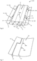
- Fig. 7 is shown schematically and by way of example, 4 electrical conductor tracks 10 may be formed on the inner surface 4a of the outer shell. As in Fig. 7 recognizable, can be in extremely space-saving manner electrical components, such as sensors 10A supply. Of course, 5 may be formed on the inner surface 5a of the inner shell electrical conductor tracks (not shown).
- the stiffening structure 3 is inserted into the interruption O of the frame structure 2.
- the stiffening structure 3 extends along the circumferential direction U between the first and the second connection section 21, 22 of the frame structure 2.
- the stiffening structure 3 extends between the first and the further frame structure 2, 20.
- the stiffening structure 3 is connected to the first and at the second connection portion 21, 22 of the frame structure 2.
- the stiffening structure 3 For connecting the stiffening structure 3 to the connecting sections 21, 22 of the frame structure 2, the stiffening structure 3 optionally has a first fastening structure 31 and a second fastening structure 33. These are in the FIGS. 4 and 5 shown schematically. Fig. 6 shows a possible design of the attachment structures 31, 33 in detail.
- the first attachment structure 31 is arranged with respect to the circumferential direction U at a first end portion 32 of the stiffening structure 3 and connected to the first connection portion 21 of the frame structure 2.
- the second Fixing structure 33 is disposed at a second end portion 34 of the stiffening structure 3 opposite to the first end portion 32 with respect to the circumferential direction U and connected to the second terminal portion 21 of the frame structure 2.
- the first attachment structure 31 and the second attachment structure 33 can each be formed by a profile carrier 37 extending in the circumferential direction U, for example a plate-shaped profile carrier 37 projecting along the circumferential direction U from the stiffening structure 3.
- the respective profile carrier 37 is connected to the respective connection section 21, 22 of the frame structure, for example by material bonding and / or by means of fastening devices 8.
- Fig. 4 shown schematically may be provided in particular that the profile carrier 37, which forms the first attachment structure 31, with the first connection portion 21 and the profile carrier 37, which forms the second attachment structure 33 overlaps with the second connection portion 22 in the circumferential direction U.
- Fig. 4 is exemplified that the second connection portion 22 of the bulkhead structure 2 by means of fastening means 8, for example in the form of rivets, with the second attachment structure 33 is connected.
- the first attachment structure 31 and the second attachment structure 33 may also be formed by a receiving recess 36 formed on a projection 35.
- the projection 35 is formed by two spaced ramps between which the receiving recess 36 extends.
- a front first attachment structure 31A for connection to the first terminal portion 21 of the first frame structure 2 and one in the longitudinal direction L spaced apart from the front first attachment structure 31A arranged rear first attachment structure 31B for connection to the first terminal portion 201 of the other frame structure 20 is provided. Furthermore, in Fig.
- connection section 21, 22 of the bulkhead structure 2 is received in the receiving recess 36 of the respective attachment structure 31, 33, as shown in FIG Fig. 5 is shown by way of example.
- a cohesive connection can be present in this case.
- the hull panel 106 may be manufactured by first providing or manufacturing the outer shell 4.
- this also applies an application of the insulating layer 9 and the conductor tracks 10, as in Fig. 7 is shown by way of example.
- the stiffening structure 3 and the inner shell 5 are provided.
- the stiffening structure 3 is connected to the inner and the outer shell 5, 4.
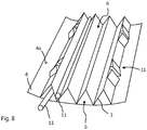
- the stiffening structure 3 may be placed on and secured to the inner surface 4a of the outer shell 4 as shown in FIG Fig. 8 is shown by way of example.
- the inner shell 5 can be fixed with its inner surface 5a to the stiffening structure 3, as in Fig. 6 shown.
- the profiled course of Stiffening structure 3 defined channel cross sections of the channels 6 inserted or inserted.
- the fuselage panel 106 may be used, for example, as the upper shell of the aircraft 100, as shown in FIGS FIGS. 1 to 3 is shown by way of example.
- a multiplicity of fuselage panels 106 adjoining one another in the longitudinal direction L are provided.
- only a single fuselage panel 106 may be provided, for example, as an upper shell.
- An advantage of the construction of the fuselage structure 1 described above is that first the frame structures 2, 20 can be mounted and connected to one another, for example by stringer 203, as shown in FIG Fig. 3 is shown schematically. The fuselage panel 106 can then be inserted from the outside into the interruptions O of the frame structures 2, 20 with respect to the radial direction R.
- FIGS. 4 and 8th are shown by way of example. These are thus accommodated with respect to the radial direction R within the fuselage structure 1 and thus taken up extremely space-saving. As in Fig. 2 can be seen, thereby a large distance in the radial direction R between a along the longitudinal axis L 100 extending bottom 205 and the in Fig. 2 used as the upper shell hull panel 106 are achieved, which is not affected by the channels 6. Another advantage is that the hull 101 can initially be mounted without the upper shell 106.
- the base 205 can be held in a simple manner from above during installation and the frame structure 2, 20 can be constructed around the base 205.
- the extension of the reinforcing layer 3 in the longitudinal direction L also ensures a planar support of the outer shell 4, which in particular can form a part of the outer skin 105 of the aircraft 100.
Landscapes
- Engineering & Computer Science (AREA)
- Aviation & Aerospace Engineering (AREA)
- Mechanical Engineering (AREA)
- Laminated Bodies (AREA)
- Moulding By Coating Moulds (AREA)
- Connection Of Plates (AREA)
- Health & Medical Sciences (AREA)
- General Health & Medical Sciences (AREA)
- Pulmonology (AREA)
Abstract
Description
- Die vorliegende Erfindung betrifft eine Rumpfstruktur für ein Luftfahrzeug sowie ein Luftfahrzeug.
- Rumpfstrukturen für Luftfahrzeuge sind üblicherweise aus in einer Längsrichtung verlaufenden Längsträgern, sogenannte Stringer, und in einer Umfangsrichtung verlaufenden, ringförmigen Umfangsträgern, sogenannten Spanten, zusammengesetzt. An diesem einen Innenraum des Luftfahrzeugs definierenden Grundgerüst wird typischerweise eine Außenhaut des Luftfahrzeugs befestigt. In dem Innenraum werden Kabinenbauteile, wie Böden, Kabinenmonumente und dergleichen angeordnet und mit der Rumpfstruktur verbunden.
- Ferner müssen in dem Innenraum des Luftfahrzeugs häufig Funktionskomponenten, wie Klimaanlagen und die zugehörigen Leitungen sowie elektrische und hydraulische Versorgungsleitungen, untergebracht werden. Hierbei besteht ein Bedarf, diese Funktionskomponenten möglichst platzsparend in den Innenraum zu integrieren.
- Die
EP 2 985 232 A1 beschreibt eine Rumpfstruktur mit Spanten und Stringern, welche durch Innenverkleidungsteile verkleidet sind. Ein sich in einer Längsrichtung erstreckendes Klimarohr ist in einem Deckenbereich angeordnet und ist in die Innenverkleidungsteile integriert. - Es ist Aufgabe der vorliegenden Erfindung, eine verbesserte Rumpfstruktur für ein Luftfahrzeug bereitzustellen.
- Diese Aufgabe wird jeweils durch die Gegenstände der unabhängigen Ansprüche gelöst.
- Vorteilhafte Ausgestaltungen und Weiterbildungen ergeben sich aus den auf die unabhängigen Ansprüche rückbezogenen Unteransprüchen in Verbindung mit der Beschreibung.
- Nach einem ersten Aspekt der Erfindung ist eine Rumpfstruktur für ein Luftfahrzeug vorgesehen. Die Rumpfstruktur weist eine sich in einer Umfangsrichtung erstreckende Spantstruktur mit einem ersten Anschlussabschnitt und einem entlang der Umfangsrichtung beabstandet zu dem ersten Anschlussabschnitt angeordneten zweiten Anschlussabschnitt auf. Die Spantstruktur kann also insbesondere als ein ringförmiger Träger oder Rahmen ausgebildet sein, wobei dieser zwischen dem ersten und dem zweiten Anschlussabschnitt eine Unterbrechung bzw. Ausnehmung aufweist.
- Die erfindungsgemäße Rumpfstruktur weist ferner eine sich zwischen dem ersten und dem zweiten Anschlussabschnitt der Spantstruktur entlang der Umfangsrichtung erstreckende und mit dem ersten und dem zweiten Anschlussabschnitt jeweils verbundene Versteifungsstruktur auf. Die Versteifungsstruktur ist also in die Ausnehmung der Spantstruktur eingesetzt bzw. setzt die Spantstruktur fort, wodurch die Spantstruktur und die Versteifungsstruktur gemeinsam einen geschlossenen Rahmen bilden.
- Eine äußere Schale, beispielsweise ein Außenhautsegment, ist an einer Außenseite der Versteifungsstruktur befestigt und eine innere Schale ist an einer entgegengesetzt zu der Außenseite gelegenen Innenseite der Versteifungsstruktur befestigt. Die Versteifungsstruktur ist demnach in Bezug auf eine radiale Richtung zwischen der inneren Schale und der äußeren Schale angeordnet und mit diesen verbunden. Die innere Schale, die äußere Schale und die Versteifungsstruktur bilden folglich eine sandwichartige Struktur. Die innere Schale und die äußere Schale können auch als innere Rumpfhaut und äußere Rumpfhaut bezeichnet werden. Durch die direkte Befestigung der inneren und der äußeren Schale an der Versteifungsstruktur weist die sandwichartige Struktur vorteilhaft eine hohe mechanische Festigkeit auf.
- Erfindungsgemäß weist die Versteifungsstruktur in einer quer zur Umfangsrichtung verlaufenden Längsrichtung gesehen einen profilierten Querschnitt auf und bildet gemeinsam mit der inneren Schale und der äußeren Schale mehrere in Umfangsrichtung nebeneinanderliegende Kanäle, welche sich jeweils in der Längsrichtung erstrecken. Die Versteifungsstruktur ist also insbesondere als ein flächiges Bauteil ausgebildet, das sich sowohl in der Umfangsrichtung als auch quer zu der Umfangsrichtung in der Längsrichtung erstreckt. Bei einem Schnitt in Umfangsrichtung bzw. quer zur Längsrichtung durch die Versteifungsstruktur ergibt sich ein Querschnittsverlauf, welcher in der Längsrichtung gesehen Erhöhungen und Vertiefungen ausbildet bzw. einen ondulierenden Verlauf aufweist. Diese in der Längsrichtung verlaufenden Erhöhungen und Vertiefungen definieren gemeinsam mit der inneren Schale und der äußeren Schale Kanalquerschnitte von sich in der Längsrichtung erstreckenden Kanälen.
- Die auf diese Weise ausgebildeten Kanäle können insbesondere als Klimakanäle oder allgemein zur Aufnahme von Funktionskomponenten genutzt werden. Dadurch wird eine multifunktionale Rumpfstruktur geschaffen. Da die Versteifungsstruktur zwischen den Anschlussabschnitten der Spantstruktur angeordnet ist, ergibt sich ein äußerst platzsparender Aufbau. Insbesondere können die Kanäle direkt in die Rumpfstruktur selbst integriert werden und es kann auf eine Anbringung der Kanäle als zusätzliche Komponenten an der Rumpfstruktur verzichtet werden. Durch den sandwichartigen Aufbau mit der zwischen der inneren und der äußeren Schale angeordneten Versteifungsstruktur wird außerdem die mechanische Festigkeit der Rumpfstruktur verbessert.
- Gemäß einer Ausführungsform der Rumpfstruktur ist die Versteifungsstruktur derart profiliert, dass diese entlang der Umfangsrichtung abwechselnd mit der äußeren Schale und der inneren Schale verbunden ist. Die vorzugsweise als einstückige flächige Schicht mit etwa konstanter Dicke ausgebildete Versteifungsstruktur kann entlang der Umfangsrichtung also einen wellenartigen Querschnittsverlauf aufweisen, beispielsweise in Form einer Sinuswelle, einer Sägezahnwelle, einer Dreieckswelle, einer Rechteckwelle oder einer trapezförmigen Welle. Allgemein ist ein periodischer Querschnittsverlauf vorteilhaft. Dadurch sowie durch die abwechselnde Verbindung mit der inneren und der äußeren Schale wird eine Biege-und insbesondere eine Schersteifigkeit der Rumpfstruktur in Umfangsrichtung weiter verbessert Außerdem wird auf diese Weise eine beulstabile Aussteifung der äußeren und der inneren Schale erzielt.
- Optional liegt die Versteifungsstruktur, die auch als Verstärkungsschicht bezeichnet werden kann, abwechselnd an der äußeren Schale und der inneren Schale an bzw. steht mit dieser in Kontakt. Dies macht den Aufbau noch kompakter und erleichtert eine direkte Kraftübertragung zwischen den Schalen und der Versteifungsstruktur.
- Gemäß einer Ausführungsform ist vorgesehen, dass die äußere Schale, die innere Schale und die Versteifungsstruktur jeweils aus einem Faserverbundmaterial gebildet sind. Faserverbundmaterialien bieten den Vorteil, dass diese bezogen auf deren Gewicht eine hohe mechanische Festigkeit aufweisen. Auch bietet Faserverbundmaterial den Vorteil, dass dieses korrosionsbeständig und ermüdungsbeständig ist, sodass auf eine entsprechende Inspektion verzichtet werden kann. Dies ist insbesondere deshalb vorteilhaft, weil die im Inneren der Rumpfstruktur durch die Verstärkungsschicht und die Schalen ausgebildeten Kanäle von außen nur schwer zugänglich sind.
- Optional können die äußere Schale, die innere Schale und die Versteifungsstruktur jeweils aus demselben Faserverbundmaterial gebildet sein. Dies erleichtert die insbesondere die Herstellung der Rumpfstruktur.
- Weiterhin optional kann auch die Spantstruktur aus einem Faserverbundmaterial, insbesondere demselben Faserverbundmaterial wie die Versteifungsstruktur gebildet sein.
- Gemäß einer Ausführungsform der Rumpfstruktur sind die äußere Schale und die innere Schale jeweils stoffschlüssig und/oder mittels Befestigungseinrichtungen mit der Versteifungsstruktur verbunden. Eine stoffschlüssige Verbindung kann beispielsweise durch Verkleben der Versteifungsstruktur mit den Schalen realisiert werden. Auch ist denkbar, die Schalen mit der Versteifungsstruktur zu verschweißen. Falls die Schalen und die Versteifungsstruktur aus einem Faserverbundmaterial gebildet sind, kann dies beispielsweise durch ein Ultraschall- oder Thermoschweißverfahren erfolgen. Alternativ oder zusätzlich oder bereichsweise kann eine Verbindung auch durch Befestigungseinrichtungen, wie z.B. Nieten, Bolzen, Schrauben, Clips oder dergleichen realisiert werden.
- Gemäß einer weiteren Ausführungsform der Rumpfstruktur ist vorgesehen, dass die Versteifungsstruktur eine erste Befestigungsstruktur, welche mit dem ersten Anschlussabschnitt der Spantstruktur verbunden ist, und eine zweite Befestigungsstruktur aufweist, welche mit dem zweiten Anschlussabschnitt der Spantstruktur verbunden ist. Demnach sind also spezielle Anschlüsse an in Bezug auf die Umfangsrichtung entgegengesetzten Endabschnitten der Versteifungsstruktur vorgesehen, welche zur Verbindung mit den Anschlussabschnitten der Spantstruktur ausgebildet sind.
- Die erste Befestigungsstruktur und/oder die zweite Befestigungsstruktur kann insbesondere durch eine an einem Vorsprung ausgebildete Aufnahmeausnehmung ausgebildet sein, in welcher der jeweilige Anschlussabschnitt der Spantstruktur aufgenommen ist. Demnach ist an der Versteifungsstruktur eine Backe mit einer Ausnehmung oder Nut vorgesehen, in welche der jeweilige Anschlussabschnitt eingeschoben ist. Vorzugsweise weist die Ausnehmung eine zu dem jeweiligen Anschlussabschnitt der Spantstruktur komplementär ausgebildete Querschnittsform auf. Durch die Aufnahme des Anschlussabschnitts in der Ausnehmung wird die Positionierung der Versteifungsstruktur relativ zur Spantstruktur bei der Montage vorteilhaft erleichtert.
- Die erste Befestigungsstruktur und/oder die zweite Befestigungsstruktur kann auch durch einen sich in der Umfangsrichtung erstreckenden Profilträger ausgebildet sein, welcher mit dem jeweiligen Anschlussabschnitt der Spantstruktur verbunden ist. Hierbei ist die Befestigungsstruktur beispielsweise durch einen plattenförmig ausgebildeten Abschnitt gebildet, der von der Versteifungsstruktur in Umfangsrichtung vorsteht.
- Optional überlappt der Profilträger mit dem jeweiligen Anschlussabschnitt der Spantstruktur in der Umfangsrichtung. Durch die Überlappung wird insbesondere die Verwindungssteifigkeit der Rumpfstruktur weiter verbessert.
- Gemäß einer Ausführungsform sind die Anschlussabschnitte der Spantstruktur mit der Versteifungsstruktur jeweils stoffschlüssig und/oder mittels Befestigungseinrichtungen verbunden. Eine stoffschlüssige Verbindung kann beispielsweise durch Verkleben oder Verschweißen realisiert werden. Alternativ oder zusätzlich oder bereichsweise kann eine Verbindung auch durch Befestigungseinrichtungen, wie z.B. Nieten, Bolzen, Schrauben, Clips oder dergleichen realisiert werden.
- Gemäß einer weiteren Ausführungsform ist vorgesehen, dass die äußere Schale an einer der Versteifungsstruktur zugewandten inneren Oberfläche eine Isolierschicht aufweist. Die Isolierschicht kann beispielsweise aus einer Mineralwolle gebildet sein. Die mittels der Isolierschicht erzielte thermische Isolationswirkung ist insbesondere für die Verwendung eines oder mehrerer der Kanäle als Klimakanal vorteilhaft, da dies den Aufwand für eine Auskleidung des Kanals reduziert.
- Gemäß einer weiteren Ausführungsform sind an der der Versteifungsstruktur zugewandten inneren Oberfläche der äußeren Schale und/oder an einer der Versteifungsstruktur zugewandten inneren Oberfläche der inneren Schale elektrische Leiterbahnen ausgebildet. Demnach ist das elektrisch leitfähige Material der Leiterbahnen direkt auf die jeweilige Schale aufgebracht, gegebenenfalls auf einen elektrisch isolierenden Bereich bzw. auf eine Isolationsschicht. Dies spart weiteren Platz für die Verkabelung.
- Gemäß einer weiteren Ausführungsform sind in den Kanälen Funktionskomponenten, insbesondere Versorgungsleitungen, wie elektrische oder hydraulische Versorgungsleitungen, angeordnet.
- Gemäß einer weiteren Ausführungsform weist die Rumpfstruktur zusätzlich eine in der Längsrichtung zu der Spantstruktur beabstandete weitere Spantstruktur mit einem ersten Anschlussabschnitt und einem entlang der Umfangsrichtung beabstandet zu dem ersten Anschlussabschnitt angeordneten zweiten Anschlussabschnitt auf. Die Versteifungsstruktur erstreckt sich zwischen dem ersten und dem zweiten Anschlussabschnitt der weiteren Spantstruktur entlang der Umfangsrichtung und ist jeweils mit dem ersten und dem zweiten Anschlussabschnitt der weiteren Spantstruktur verbunden.
- Gemäß einem weiteren Aspekt der Erfindung ist ein Luftfahrzeug mit einer Rumpfstruktur gemäß einer der voranstehend beschriebenen Ausführungsformen vorgesehen. Insbesondere kann es sich hierbei um ein Passagierflugzeug handeln. Die äußere Schale der Rumpfstruktur bildet hierbei vorzugsweise einen Teil einer Außenhaut des Luftfahrzeugs.
- In Bezug auf Richtungsangaben und Achsen, insbesondere auf Richtungsangaben und Achsen, die den Verlauf von physischen Strukturen betreffen, wird hierin unter einem Verlauf einer Achse, einer Richtung oder einer Struktur "entlang" einer anderen Achse, Richtung oder Struktur verstanden, dass diese, insbesondere die sich in einer jeweiligen Stelle der Strukturen ergebenden Tangenten jeweils in einem Winkel von kleiner oder gleich 45 Grad, bevorzugt kleiner oder gleich 30 Grad und insbesondere bevorzugt parallel zueinander verlaufen.
- In Bezug auf Richtungsangaben und Achsen, insbesondere auf Richtungsangaben und Achsen, die den Verlauf von physischen Strukturen betreffen, wird hierin unter einem Verlauf einer Achse, einer Richtung oder einer Struktur "quer" zu einer anderen Achse, Richtung oder Struktur verstanden, dass diese, insbesondere die sich in einer jeweiligen Stelle der Strukturen ergebenden Tangenten jeweils in einem Winkel von größer 45 Grad, bevorzugt größer 60 Grad und insbesondere bevorzugt senkrecht zueinander verlaufen.
- Hierin wird unter einem "Faserwerkstoff", einem "Fasermaterial", einem "Faserverbundmaterial" oder einem "Faserverbundwerkstoff" allgemein ein
- Werkstoff verstanden, der aus einer Vielzahl von insbesondere fadenförmigen oder fadenstückförmigen Verstärkungsfasern, wie beispielsweise Kohle-, Glas-, Keramik-, Aramid-, Bor-, Mineral-, Natur- oder Kunststofffasern oder Mischungen aus diesen gebildet ist. Der Faserwerkstoff kann insbesondere auch mit einem Harz- oder Matrixmaterial wie z.B. einem duroplastischen, thermoplastischen, elastomeren Harz oder allgemein ein Kunststoffharz oder dergleichen imprägniert sein.
- Im Folgenden wird die Erfindung unter Bezugnahme auf die Figuren der Zeichnungen erläutert. Von den Figuren zeigen:
- Fig. 1
- eine schematische Ansicht eines Luftfahrzeugs gemäß einem Ausführungsbeispiel der vorliegenden Erfindung in einer Draufsicht;
- Fig. 2
- eine schematische Schnittansicht einer Rumpfstruktur gemäß einem Ausführungsbeispiel der vorliegenden Erfindung;
- Fig. 3
- eine perspektivische Teilansicht eines Luftfahrzeugs gemäß einem Ausführungsbeispiel der vorliegenden Erfindung in einer schematischen Explosionsdarstellung;
- Fig. 4
- eine abgebrochene Schnittdarstellung einer Rumpfstruktur gemäß einem Ausführungsbeispiel der vorliegenden Erfindung;
- Fig. 5
- eine abgebrochene Schnittdarstellung einer Rumpfstruktur gemäß einem weiteren Ausführungsbeispiel der vorliegenden Erfindung;
- Fig. 6
- eine perspektivische Teilansicht einer Rumpfstruktur gemäß einem weiteren Ausführungsbeispiel der vorliegenden Erfindung mit einer Blickrichtung auf eine innere Schale der Rumpfstruktur;
- Fig. 7
- eine perspektivische Ansicht einer äußeren Schale einer Rumpfstruktur gemäß einem weiteren Ausführungsbeispiel der vorliegenden Erfindung mit einer Blickrichtung auf eine innere Oberfläche der äußeren Schale; und
- Fig. 8
- eine perspektivische Teilansicht einer Rumpfstruktur gemäß einem weiteren Ausführungsbeispiel der vorliegenden Erfindung.
- In den Figuren bezeichnen dieselben Bezugszeichen gleiche oder funktionsgleiche Komponenten, soweit nichts Gegenteiliges angegeben ist.
-
Fig. 1 zeigt eine Luftfahrzeug 100 in einer Draufsicht. Das Luftfahrzeug weist einen sich in einer Längsrichtung L erstreckenden Rumpf 101, Tragflächen 102, ein Höhenleitwerk 103 und ein Seitenleitwerk 104 auf. Der Rumpf 101 weist eine inFig. 1 lediglich schematisch dargestellte Rumpfstruktur 1 mit mehreren Spanten 2, 20 sowie eine Außenhaut 105 auf. Wie inFig. 1 weiterhin dargestellt, ist ein Teilbereich der Außenhaut 105 durch zumindest eine äußere Schale 4 der Rumpfstruktur 1 gebildet. InFig. 1 ist beispielhaft dargestellt, dass eine Vielzahl von entlang der Längsrichtung L hintereinander angeordneter äußerer Schalen 4 vorgesehen ist, welche einen Teilbereich der Außenhaut 105 bilden. -
Fig. 2 zeigt beispielhaft und schematisch eine Schnittansicht der Rumpfstruktur 1. InFig. 3 ist eine perspektivische Teilschnittansicht des Rumpfs 101 gezeigt, welcher die Rumpfstruktur 1 aufweist. Die Rumpfstruktur 1 weist eine erste Spantstruktur 2, eine oder mehrere optionale zweite Spantstrukturen 20, eine Versteifungsstruktur oder Verstärkungsschicht 3, eine äußere Schale 4 und eine innere Schale 5 auf. - Nachfolgend wird insbesondere die erste Spantstruktur 2 näher erläutert. Die Ausführungen gelten jedoch gleichermaßen auch für die optionalen weiteren Spantstrukturen 20. Wie in
Fig. 2 gezeigt ist, sind die erste Spantstruktur 2 und die optionale zweite Spantstruktur 20 in der Längsrichtung L beabstandet zueinander angeordnet. Wie insbesondere inFig. 2 beispielhaft dargestellt ist, können die Spantstrukturen 2, 20 insbesondere als Ringsegmente ausgebildet sein. Allgemein erstrecken sich die Spantstrukturen 2, 20 in einer Umfangsrichtung U und umschließen damit zumindest teilweise eine Längsachse L100 des Luftfahrzeugs, die sich entlang der Längsrichtung L erstreckt. Die Umfangsrichtung U und die Längsrichtung L erstrecken sich quer zueinander. Die Spantstruktur 2 kann beispielsweise durch einen einzigen Profilträger oder durch mehrere sich in Umfangsrichtung aneinander anschließende Profilträgersegmente zusammengesetzt sein. Die Spantstruktur 2 kann beispielsweise einen Z-förmigen oder ähnlichen Querschnitt aufweisen. - Die Spantstruktur 2 weist einen ersten Anschlussabschnitt 21 und einen zweiten Anschlussabschnitt 22 auf. Die Anschlussabschnitte 21, 22 sind zur Befestigung der Versteifungsstruktur 3 vorgesehen und bilden in Bezug auf die Umfangsrichtung U jeweils ein Ende der Spantstruktur 2. Insbesondere sind der erste und der zweite Anschlussabschnitt 21, 22 entlang der Umfangsrichtung U beabstandet zueinander angeordnet. Wie insbesondere in
Fig. 3 erkennbar ist, begrenzen die Anschlussabschnitte 21, 22 der Spantstruktur 2 dadurch eine Öffnung oder Unterbrechung O der Spantstruktur 2. - Wie insbesondere in den
Figuren 4 und 5 erkennbar ist, welche jeweils eine abgebrochene Schnittansicht der Rumpfstruktur 1 zeigen, ist die Versteifungsstruktur 3 in Bezug auf eine radiale Richtung R, die sich quer zur Umfangsrichtung U und quer zur Längsrichtung L erstreckt, zwischen der äußeren Schale 4 und der inneren Schale 5 angeordnet. - Die äußere und die innere Schale 4, 5 sind jeweils als sich flächig entlang der Längsrichtung L und entlang der Umfangsrichtung U erstreckende Bauteile realisiert, insbesondere als gekrümmte, entlang einander verlaufende Platten. Die Schalen 4, 5 sind optional jeweils aus einem Faserverbundmaterial gebildet.
- Die Versteifungsstruktur 3 ist als eine sich flächig in der Längsrichtung L und der Umfangsrichtung U erstreckende Schicht oder Lage realisiert und weist in der Längsrichtung L gesehen einen profilierten Querschnitt auf. Insbesondere kann die Versteifungsstruktur 3 einen zickzackartigen, insbesondere Dreiecke bildenden Querschnittsverlauf entlang der Umfangsrichtung U aufweisen, wie dies beispielhaft in
Fig. 4 dargestellt ist.Fig. 5 zeigt beispielhaft einen Trapeze bildenden Querschnittsverlauf entlang der Umfangsrichtung U. Selbstverständlich kann auch ein Querschnittsverlauf entlang der Umfangsrichtung U vorgesehen sein, der etwa sinuswellenförmig ist. Die Versteifungsstruktur 3 kann insbesondere aus einem Faserverbundmaterial gebildet sein. Vorzugsweise sind die Versteifungsstruktur 3 sowie die Schalen 4, 5 aus demselben Faserverbundmaterial gebildet. - Wie insbesondere in den
Figuren 3 und 4 dargestellt ist, ist die Versteifungsstruktur 3 in Bezug auf die radiale Richtung R zwischen der äußeren und der inneren Schale 4, 5 angeordnet. Die äußere Schale 4 ist damit an einer Außenseite 3A der Versteifungsstruktur 3 angeordnet und insbesondere an dieser befestigt. Die innere Schale 5 ist an einer in Bezug auf die radiale Richtung R entgegengesetzt zu der Außenseite 3A gelegenen Innenseite 3B der Versteifungsstruktur 3 angeordnet und insbesondere an dieser befestigt. - Wie in den
Figuren 4 und 5 gezeigt ist, bildet die Versteifungsstruktur 3 aufgrund des profilierten Querschnitts gemeinsam mit der inneren Schale 5 und der äußeren Schale 4 mehrere in Umfangsrichtung U nebeneinanderliegende Kanäle 6, welche sich jeweils in der Längsrichtung L erstrecken. Insbesondere kann die Versteifungsstruktur 3 derart profiliert sein, dass diese entlang der Umfangsrichtung U abwechselnd mit der äußeren Schale 4 und der inneren Schale 5 verbunden ist, wie dies in denFiguren 4 und 5 beispielhaft dargestellt ist. InFig. 4 ist dies dadurch realisiert, dass die Versteifungsstruktur 3 dreieckförmig profiliert ist, inFig. 5 durch eine trapezförmige Profilierung. - Optional kann weiterhin vorgesehen sein, dass die Versteifungsstruktur 3 entlang der Umfangsrichtung U abwechselnd an der äußeren Schale 4 und der inneren Schale 5 anliegt. Hierbei weist die Versteifungsstruktur 3 mehrere in der Umfangsrichtung U beabstandete äußere Anlagebereiche 30A auf, welche sich in der Längsrichtung L erstrecken und an der äußeren Schale 4 anliegen und mit dieser verbunden sind. Weiterhin weist die Versteifungsstruktur 3 mehrere in der Umfangsrichtung U beabstandete innere Anlagebereiche 30B auf, welche sich in der Längsrichtung L erstrecken und an der inneren Schale 5 anliegen und mit dieser verbunden sind. Wie in den
Figuren 4 und 5 dargestellt, sind die inneren Anlagebereiche 30B und die äußeren Anlagebereiche 30A entlang der Umfangsrichtung U abwechselnd angeordnet. - Die äußere Schale 4 und die innere Schale 5 können jeweils stoffschlüssig mit der Versteifungsstruktur 3 verbunden sein, beispielsweise durch Verschweißen entlang der optionalen Anlagebereiche 30A, 30B, wie dies in
Fig. 4 und6 symbolisch dargestellt ist. Alternativ oder zusätzlich können Befestigungseinrichtungen 7 zur Befestigung der Schalen 4, 5 an der Versteifungsstruktur 3 vorgesehen sein, z.B. in Form von Schrauben oder Nieten. Dies ist inFig. 5 schematisch dargestellt. - Wie in
Fig. 4 schematisch dargestellt ist, kann die äußere Schale 4 an einer der Versteifungsstruktur 3 zugewandten inneren Oberfläche 4a eine Isolierschicht 9, z.B in Form einer Mineralwollschicht, aufweisen. Wie inFig. 4 beispielhaft dargestellt, ist jeweils zwischen zwei benachbarten äußeren Anlagebereichen 30A, an denen die Versteifungsstruktur 3 an der inneren Oberfläche 4a der äußeren Schale 4 anliegt, ein Abschnitt der Isolierschicht 9 vorgesehen. Optional kann auch an einer der Versteifungsstruktur 3 zugewandten inneren Oberfläche 5a der inneren Schale 5 eine Isolierschicht (nicht dargestellt) vorgesehen sein. - Wie in
Fig. 7 schematisch und beispielhaft gezeigt ist, können an der inneren Oberfläche 4a der äußeren Schale 4 elektrische Leiterbahnen 10 ausgebildet sein. Wie inFig. 7 erkennbar, lassen sich dadurch in äußerst platzsparender Weise elektrische Komponenten, wie z.B. Sensoren 10A, versorgen. Selbstverständlich können auch auf der inneren Oberfläche 5a der inneren Schale 5 elektrische Leiterbahnen (nicht dargestellt) ausgebildet sein. - Die Versteifungsstruktur 3 bildet gemeinsam mit der inneren Schale 5 und der äußeren Schale 4 ein Rumpfpanel 106.
- Wie in
Fig. 2 schematisch dargestellt ist, ist die Versteifungsstruktur 3 in die Unterbrechung O der Spantstruktur 2 eingesetzt. Insbesondere erstreckt sich die Versteifungsstruktur 3 entlang der Umfangsrichtung U zwischen dem ersten und dem zweiten Anschlussabschnitt 21, 22 der Spantstruktur 2. Im Falle einer optionalen weiteren Spantstruktur 20 erstreckt sich die Versteifungsstruktur 3 zwischen der ersten und der weiteren Spantstruktur 2, 20. Die Versteifungsstruktur 3 ist mit dem ersten und an dem zweiten Anschlussabschnitt 21, 22 der Spantstruktur 2 verbunden. - Zur Verbindung der Versteifungsstruktur 3 mit den Anschlussabschnitten 21, 22 der Spantstruktur 2 weist die Versteifungsstruktur 3 optional eine erste Befestigungsstruktur 31 und eine zweite Befestigungsstruktur 33 auf. Diese sind in den
Figuren 4 und 5 schematisch dargestellt.Fig. 6 zeigt eine mögliche Gestaltung der der Befestigungsstrukturen 31, 33 im Detail. - Die erste Befestigungsstruktur 31 ist in Bezug auf die Umfangsrichtung U an einem ersten Endabschnitt 32 der Versteifungsstruktur 3 angeordnet und mit dem ersten Anschlussabschnitt 21 der Spantstruktur 2 verbunden. Die zweite Befestigungsstruktur 33 ist an einem in Bezug auf die Umfangsrichtung U entgegengesetzt zu dem ersten Endabschnitt 32 gelegenen zweiten Endabschnitt 34 der Versteifungsstruktur 3 angeordnet und mit dem zweiten Anschlussabschnitt 21 der Spantstruktur 2 verbunden.
- Wie in den
Figuren 3 und 4 beispielhaft gezeigt ist, können die erste Befestigungsstruktur 31 und die zweite Befestigungsstruktur 33 jeweils durch einen sich in der Umfangsrichtung U erstreckenden, beispielsweise plattenförmigen Profilträger 37 ausgebildet sein, welcher entlang der Umfangsrichtung U von der Versteifungsstruktur 3 vorspringt. Der jeweilige Profilträger 37 wird mit dem jeweiligen Anschlussabschnitt 21, 22 der Spantstruktur verbunden, beispielsweise stoffschlüssig und/oder mittels Befestigungseinrichtungen 8. - Wie in
Fig. 4 schematisch dargestellt, kann insbesondere vorgesehen sein, dass der Profilträger 37, der die erste Befestigungsstruktur 31 bildet, mit dem ersten Anschlussabschnitt 21 und der Profilträger 37, der die zweite Befestigungsstruktur 33 bildet, mit dem zweiten Anschlussabschnitt 22 in der Umfangsrichtung U überlappt. InFig. 4 ist beispielhaft dargestellt, dass der zweite Anschlussabschnitt 22 der Spantstruktur 2 mittels Befestigungseinrichtungen 8, z.B. in Form von Nieten, mit der zweite Befestigungsstruktur 33 verbunden ist. - Wie insbesondere in
Fig. 6 beispielhaft dargestellt ist, können die erste Befestigungsstruktur 31 und die zweite Befestigungsstruktur 33 auch durch eine an einem Vorsprung 35 ausgebildete Aufnahmeausnehmung 36 ausgebildet sein. InFig. 6 ist der Vorsprung 35 beispielhaft durch zwei beabstandete Rampen ausgebildet, zwischen welchen sich die Aufnahmeausnehmung 36 erstreckt. InFig. 6 sind eine vordere erste Befestigungsstruktur 31A zur Verbindung mit dem ersten Anschlussabschnitt 21 der ersten Spantstruktur 2 und eine in der Längsrichtung L beabstandet zu der vorderen ersten Befestigungsstruktur 31A angeordnete hintere erste Befestigungsstruktur 31B zur Verbindung mit dem ersten Anschlussabschnitt 201 der weiteren Spantstruktur 20 vorgesehen. Ferner sind inFig. 6 eine vordere zweite Befestigungsstruktur 33A zur Verbindung mit dem zweiten Anschlussabschnitt 22 der ersten Spantstruktur 2 und eine in der Längsrichtung L beabstandet zu der vorderen zweiten Befestigungsstruktur 33A angeordnete hintere zweite Befestigungsstruktur 33B zur Verbindung mit dem zweiten Anschlussabschnitt 202 der weiteren Spantstruktur 20 vorgesehen. - Zur Verbindung mit der Spantstruktur 2 ist der jeweilige Anschlussabschnitt 21, 22 der Spantstruktur 2 in der Aufnahmeausnehmung 36 der jeweiligen Befestigungsstruktur 31, 33 aufgenommen, wie dies in
Fig. 5 beispielhaft dargestellt ist. Insbesondere kann in diesem Fall eine stoffschlüssige Verbindung vorliegen. - Das Rumpfpanel 106 kann beispielsweise hergestellt werden, indem zunächst die äußere Schale 4 bereitgestellt oder hergestellt wird. Optional erfolgt hierbei auch ein Aufbringen der Isolierschicht 9 und der Leiterbahnen 10, wie in
Fig. 7 beispielhaft dargestellt ist. Ferner werden die Versteifungsstruktur 3 und die innere Schale 5 bereitgestellt bzw. hergestellt. Die Versteifungsstruktur 3 wird mit der inneren und der äußeren Schale 5, 4 verbunden. Beispielsweise kann die Versteifungsstruktur 3 auf die innere Oberfläche 4a der äußeren Schale 4 aufgelegt und an dieser befestigt werden, wie dies inFig. 8 beispielhaft dargestellt ist. Anschließend kann die innere Schale 5 mit deren innerer Oberfläche 5a an der Versteifungsstruktur 3 befestigt werden, wie inFig. 6 dargestellt. Optional können bereits vor der Anbringung der inneren Schale 5 Funktionskomponenten 11, wie Rohre oder dergleichen, in die durch den profilierten Verlauf der Versteifungsstruktur 3 definierten Kanalquerschnitte der Kanäle 6 eingelegt bzw. eingeschoben werden. - Das Rumpfpanel 106 kann beispielsweise als Oberschale des Luftfahrzeugs 100 verwendet werden, wie dies in den
Figuren 1 bis 3 beispielhaft dargestellt ist. InFig. 1 sind beispielhaft eine Vielzahl von in Längsrichtung L aneinander anschließende Rumpfpanelen 106 vorgesehen. Selbstverständlich kann auch lediglich ein einziges Rumpfpanel 106 vorgesehen sein, beispielsweise als Oberschale. Ein Vorteil des voranstehend beschriebenen Aufbaus der Rumpfstruktur 1 besteht darin, dass zunächst die Spantstrukturen 2, 20 montiert und beispielsweise durch Stringer 203 untereinander verbunden werden können, wie dies inFig. 3 schematisch dargestellt ist. Das Rumpfpanel 106 kann dann in Bezug auf die radiale Richtung R von außen in die Unterbrechungen O der Spantstrukturen 2, 20 eingesetzt werden. - Durch die profilierte Gestaltung der Versteifungsstruktur 3 bildet diese gemeinsam mit den Schalen 4, 5 Kanäle 6 aus. In diesen können Funktionskomponenten 11, insbesondere Versorgungsleitungen angeordnet werden, wie dies in den
Figuren 4 und8 beispielhaft dargestellt ist. Diese sind damit in Bezug auf die radiale Richtung R innerhalb der Rumpfstruktur 1 untergebracht und damit äußerst platzsparend aufgenommen. Wie inFig. 2 erkennbar ist, kann dadurch ein großer Abstand in der radialen Richtung R zwischen einem sich entlang der Längsachse L 100 erstreckenden Boden 205 und dem inFig. 2 als Oberschale verwendeten Rumpfpanel 106 erzielt werden, der nicht durch die Kanäle 6 beeinträchtigt wird. Ein weiterer Vorteil liegt darin, dass der Rumpf 101 zunächst ohne die Oberschale 106 montiert werden kann. Dadurch kann der Boden 205 während der Montage auf einfache Weise von oben her gehalten und die Spantstruktur 2, 20 um den Boden 205 herum aufgebaut werden. Darüber hinaus können Kabinenkomponenten, wie z.B. Sitze oder dergleichen, durch die Öffnung O der Spantstruktur 2, 20 in das Rumpfinnere befördert werden. - Durch die Erstreckung der Verstärkungsschicht 3 in der Längsrichtung L wird auch eine flächige Unterstützung der äußeren Schale 4 gewährleistet, welche insbesondere einen Teil der Außenhaut 105 des Luftfahrzeugs 100 bilden kann.
- Obwohl die vorliegende Erfindung vorstehend anhand von Ausführungsbeispielen exemplarisch erläutert wurde, ist sie darauf nicht beschränkt, sondern auf vielfältige Weise modifizierbar. Insbesondere sind auch Kombinationen der voranstehenden Ausführungsbeispiele denkbar.
-
- 1
- Rumpfstruktur
- 2
- Spantstruktur
- 3
- Versteifungsstruktur
- 3A
- Außenseite der Versteifungsstruktur
- 3B
- Innenseite der Versteifungsstruktur
- 4
- äußere Schale
- 4a
- innere Oberfläche der äußeren Schale
- 5
- innere Schale
- 5a
- innere Oberfläche der inneren Schale
- 6
- Kanäle
- 7
- Befestigungseinrichtungen
- 8
- Befestigungseinrichtungen
- 9
- Isolierschicht
- 10
- Leiterbahnen
- 10A
- Sensoren
- 11
- Funktionskomponenten
- 20
- weitere Spantstruktur
- 21
- erster Anschlussabschnitt
- 22
- zweiter Anschlussabschnitt
- 30A
- äußere Anlagebereiche
- 30B
- innere Anlagebereiche
- 31
- erste Befestigungsstruktur
- 31A
- vordere erste Befestigungsstruktur
- 32
- erster Endabschnitt der Versteifungsstruktur
- 33
- zweite Befestigungsstruktur
- 34
- zweiter Endabschnitt der Versteifungsstruktur
- 35
- Vorsprung
- 36
- Aufnahmeausnehmung
- 100
- Luftfahrzeug
- 101
- Rumpf
- 102
- Tragflächen
- 103
- Höhenleitwerk
- 104
- Seitenleitwerk
- 105
- Außenhaut
- 106
- Rumpfpanel
- 201
- erster Anschlussabschnitt der weiteren Spantstruktur
- 202
- zweiter Anschlussabschnitt der weiteren Spantstruktur
- 203
- Stringer
- 205
- Boden
- O
- Unterbrechung der Spantstruktur
- U
- Umfangsrichtung
- L
- Längsrichtung
- L100
- Längsachse des Luftfahrzeugs
Claims (15)
- Rumpfstruktur (1) für ein Luftfahrzeug (100), mit:einer sich in einer Umfangsrichtung (U) erstreckenden Spantstruktur (2) mit einem ersten Anschlussabschnitt (21) und einem entlang der Umfangsrichtung (U) beabstandet zu dem ersten Anschlussabschnitt (21) angeordneten zweiten Anschlussabschnitt (22);einer sich zwischen dem ersten und dem zweiten Anschlussabschnitt (21; 22) der Spantstruktur (2) entlang der Umfangsrichtung (U) erstreckenden und mit dem ersten und dem zweiten Anschlussabschnitt (21; 22) jeweils verbundenen Versteifungsstruktur (3);einer äußeren Schale (4), welche an einer Außenseite (3A) der Versteifungsstruktur (3) befestigt ist; undeiner inneren Schale (5), welche an einer entgegengesetzt zu der Außenseite (3A) gelegenen Innenseite (3B) der Versteifungsstruktur (3) befestigt ist,wobei die Versteifungsstruktur (3) in einer quer zur Umfangsrichtung (U) verlaufenden Längsrichtung (L) gesehen einen profilierten Querschnitt aufweist und gemeinsam mit der inneren Schale (5) und der äußeren Schale (4) mehrere in Umfangsrichtung (U) nebeneinanderliegende Kanäle (6) bildet, welche sich jeweils in der Längsrichtung (L) erstrecken.
- Rumpfstruktur (1) nach Anspruch 1, wobei die Versteifungsstruktur (3) derart profiliert ist, dass diese entlang der Umfangsrichtung (U) abwechselnd mit der äußeren Schale (4) und der inneren Schale (5) verbunden ist, insbesondere abwechselnd an der äußeren Schale (4) und der inneren Schale (5) anliegt.
- Rumpfstruktur (1) nach Anspruch 1 oder 2, wobei die äußere Schale (4), die innere Schale (5) und die Versteifungsstruktur (3) jeweils aus einem Faserverbundmaterial gebildet sind.
- Rumpfstruktur (1) nach Anspruch 3, wobei die äußere Schale (4), die innere Schale (5) und die Versteifungsstruktur (3) jeweils aus demselben Faserverbundmaterial gebildet sind.
- Rumpfstruktur (1) nach einem der voranstehenden Ansprüche, wobei die äußere Schale (4) und die innere Schale (5) jeweils stoffschlüssig und/oder mittels Befestigungseinrichtungen (7) mit der Versteifungsstruktur (3) verbunden sind.
- Rumpfstruktur (1) nach einem der voranstehenden Ansprüche, wobei die Versteifungsstruktur (3) eine erste Befestigungsstruktur (31), die mit dem ersten Anschlussabschnitt (21) der Spantstruktur (2) verbunden ist, und eine zweite Befestigungsstruktur (33) aufweist, welche mit dem zweiten Anschlussabschnitt (21) der Spantstruktur (2) verbunden ist.
- Rumpfstruktur (1) nach Anspruch 6, wobei die erste Befestigungsstruktur (31) und/oder die zweite Befestigungsstruktur (33) durch eine an einem Vorsprung (35) ausgebildete Aufnahmeausnehmung (36) ausgebildet ist, in welcher der jeweilige Anschlussabschnitt (21; 22) der Spantstruktur (2) aufgenommen ist.
- Rumpfstruktur (1) nach Anspruch 6, wobei die erste Befestigungsstruktur (31) und/oder die zweite Befestigungsstruktur (33) durch einen sich in der Umfangsrichtung (U) erstreckende Profilträger (37) ausgebildet sind, welcher mit dem jeweiligen Anschlussabschnitt (21; 22) der Spantstruktur verbunden ist.
- Rumpfstruktur (1) nach Anspruch 8, wobei der Profilträger (37) mit dem jeweiligen Anschlussabschnitt (21; 22) der Spantstruktur (2) in der Umfangsrichtung (U) überlappt.
- Rumpfstruktur (1) nach einem der voranstehenden Ansprüche, wobei die Anschlussabschnitte (21; 22) der Spantstruktur (2) mit der Versteifungsstruktur (3) jeweils stoffschlüssig und/oder mittels Befestigungseinrichtungen (8) verbunden sind.
- Rumpfstruktur (1) nach einem der voranstehenden Ansprüche, wobei die äußere Schale (4) an einer der Versteifungsstruktur (3) zugewandten inneren Oberfläche (4a) eine Isolierschicht (9) aufweist.
- Rumpfstruktur (1) nach einem der voranstehenden Ansprüche, wobei an einer der Versteifungsstruktur (3) zugewandten inneren Oberfläche (4a) der äußeren Schale (4) und/oder an einer der Versteifungsstruktur (3) zugewandten inneren Oberfläche (5a) der inneren Schale (5) elektrische Leiterbahnen (10) ausgebildet sind.
- Rumpfstruktur (1) nach einem der voranstehenden Ansprüche, wobei in den Kanälen (6) Funktionskomponenten (11), insbesondere Versorgungsleitungen, angeordnet sind.
- Rumpfstruktur (1) nach einem der voranstehenden Ansprüche, zusätzlich aufweisend:eine in der Längsrichtung (L) zu der Spantstruktur (2) beabstandete weitere Spantstruktur (20) mit einem ersten Anschlussabschnitt (201) und einem entlang der Umfangsrichtung (U) beabstandet zu dem ersten Anschlussabschnitt (201) angeordneten zweiten Anschlussabschnitt (202),wobei die Versteifungsstruktur (3) sich zwischen dem ersten und dem zweiten Anschlussabschnitt (201; 202) der weiteren Spantstruktur (20) entlang der Umfangsrichtung (U) erstreckt und mit dem ersten und dem zweiten Anschlussabschnitt (201; 202) der weiteren Spantstruktur (20) jeweils verbunden ist.
- Luftfahrzeug (100) mit einer Rumpfstruktur (1) gemäß einem der voranstehenden Ansprüche.
Applications Claiming Priority (1)
| Application Number | Priority Date | Filing Date | Title |
|---|---|---|---|
| DE102018207763.0A DE102018207763A1 (de) | 2018-05-17 | 2018-05-17 | Rumpfstruktur für ein Luftfahrzeug |
Publications (2)
| Publication Number | Publication Date |
|---|---|
| EP3569494A1 true EP3569494A1 (de) | 2019-11-20 |
| EP3569494B1 EP3569494B1 (de) | 2021-07-28 |
Family
ID=66448362
Family Applications (1)
| Application Number | Title | Priority Date | Filing Date |
|---|---|---|---|
| EP19172960.7A Active EP3569494B1 (de) | 2018-05-17 | 2019-05-07 | Rumpfstruktur für ein luftfahrzeug |
Country Status (6)
| Country | Link |
|---|---|
| US (1) | US11697487B2 (de) |
| EP (1) | EP3569494B1 (de) |
| CN (1) | CN110498033A (de) |
| CA (1) | CA3042477A1 (de) |
| DE (1) | DE102018207763A1 (de) |
| ES (1) | ES2894905T3 (de) |
Cited By (1)
| Publication number | Priority date | Publication date | Assignee | Title |
|---|---|---|---|---|
| CN115258128A (zh) * | 2022-09-27 | 2022-11-01 | 成都市鸿侠科技有限责任公司 | 用于飞机壁板加工的加固结构 |
Families Citing this family (5)
| Publication number | Priority date | Publication date | Assignee | Title |
|---|---|---|---|---|
| RU202616U1 (ru) * | 2020-11-02 | 2021-03-01 | Федеральное государственное бюджетное образовательное учреждение высшего образования "Казанский национальный исследовательский технический университет им. А.Н. Туполева - КАИ" | Фюзеляж летательного аппарата из ферменного заполнителя |
| CN113665782A (zh) * | 2021-09-24 | 2021-11-19 | 肇庆市海特复合材料技术研究院 | 一种复合材料无人机粘接结构及其粘接方法 |
| CN114046694A (zh) * | 2021-11-03 | 2022-02-15 | 天津爱思达航天科技有限公司 | 复材壳体连接框加强结构 |
| US20250368311A1 (en) * | 2024-05-29 | 2025-12-04 | The Boeing Company | Panel assembly for converting passenger aircraft to cargo aircraft |
| EP4729409A1 (de) * | 2024-10-17 | 2026-04-22 | AIRBUS Operations GmbH | Rumpfrahmen |
Citations (4)
| Publication number | Priority date | Publication date | Assignee | Title |
|---|---|---|---|---|
| JPH04117747A (ja) * | 1990-09-07 | 1992-04-17 | Oki Electric Ind Co Ltd | ネットワークシステムの被管理ノード計算機 |
| US7025305B2 (en) * | 2001-06-07 | 2006-04-11 | Saab Ab | Aircraft panel |
| EP2985232A1 (de) | 2014-08-13 | 2016-02-17 | Airbus Operations GmbH | Verfahren zur Montage eines Flugzeugrumpfes |
| US20160368586A1 (en) * | 2013-12-18 | 2016-12-22 | Airbus Defence and Space GmbH | Production method for producing a load-bearing fuselage panel and fuselage panel producible therewith |
Family Cites Families (17)
| Publication number | Priority date | Publication date | Assignee | Title |
|---|---|---|---|---|
| GB428225A (en) * | 1933-11-09 | 1935-05-09 | A T S Company Ltd | Improvements in metal framework for aircraft |
| FR797149A (fr) * | 1935-10-31 | 1936-04-21 | Perfectionnements à la construction des fuselages, carrosseries, etc. | |
| GB1381183A (en) * | 1972-03-30 | 1975-01-22 | Imp Metal Ind Kynoch Ltd | Method of making structural metal panels |
| JPH0716968A (ja) * | 1993-06-29 | 1995-01-20 | Akiya Ozeki | 高強度軽量立体構造の製造方法。 |
| GB9400577D0 (en) * | 1994-01-13 | 1994-03-09 | Britsh Aerospace Public Limite | Forming of structures |
| US6958105B2 (en) * | 2002-08-08 | 2005-10-25 | Airbus Deutschland Gmbh | Automated fabrication of an integral fiber reinforced composite structural component using a positioning and assembly support |
| WO2008025860A1 (es) * | 2006-08-31 | 2008-03-06 | Airbus España, S.L. | Componentes tubulares para fuselajes aeronauticos y procedimientos y utiles para su fabricacion |
| DE102007008988A1 (de) * | 2007-02-23 | 2008-08-28 | Airbus Deutschland Gmbh | Rumpf eines Luft-oder Raumfahrzeugs und ein entsprechendes Luft-oder Raumfahrzeug |
| US8834667B2 (en) * | 2010-10-19 | 2014-09-16 | The Boeing Company | Method for joining sandwich truss core panels and composite structures produced therefrom |
| ES2382765B1 (es) * | 2009-06-29 | 2013-05-03 | Airbus Operations, S.L. | Diseño de cuadernas de aeronave |
| FR2984845B1 (fr) * | 2011-12-21 | 2014-07-11 | Airbus Operations Sas | Element de structure de fuselage d'aeronef anti deversement |
| JP6238168B2 (ja) * | 2014-02-04 | 2017-11-29 | 三菱重工業株式会社 | 複合材構造 |
| US10272619B2 (en) * | 2014-05-19 | 2019-04-30 | The Boeing Company | Manufacture of a resin infused one-piece composite truss structure |
| US20160129985A1 (en) * | 2014-11-08 | 2016-05-12 | Airbus Group India Private Limited | Aircraft structure having cables located in stringers |
| EP3109152B1 (de) * | 2015-06-24 | 2019-08-07 | Airbus Operations GmbH | Versteifte rumpfkomponente sowie verfahren und vorrichtung zur herstellung einer versteiften rumpfkomponente |
| US11383817B2 (en) * | 2019-07-19 | 2022-07-12 | The Boeing Company | Modular fuselage assemblies for aircraft, aircraft including modular fuselage assemblies, and MEl'hods of assembling modular fuselage assemblies |
| DE102019211434B3 (de) * | 2019-07-31 | 2020-11-05 | Premium Aerotec Gmbh | Spantkomponente und verfahren zur herstellung einer spantkomponente, spant und rumpfstruktur für ein luftfahrzeug |
-
2018
- 2018-05-17 DE DE102018207763.0A patent/DE102018207763A1/de not_active Withdrawn
-
2019
- 2019-05-07 EP EP19172960.7A patent/EP3569494B1/de active Active
- 2019-05-07 ES ES19172960T patent/ES2894905T3/es active Active
- 2019-05-07 CA CA3042477A patent/CA3042477A1/en active Pending
- 2019-05-08 US US16/406,370 patent/US11697487B2/en active Active
- 2019-05-16 CN CN201910409604.4A patent/CN110498033A/zh active Pending
Patent Citations (4)
| Publication number | Priority date | Publication date | Assignee | Title |
|---|---|---|---|---|
| JPH04117747A (ja) * | 1990-09-07 | 1992-04-17 | Oki Electric Ind Co Ltd | ネットワークシステムの被管理ノード計算機 |
| US7025305B2 (en) * | 2001-06-07 | 2006-04-11 | Saab Ab | Aircraft panel |
| US20160368586A1 (en) * | 2013-12-18 | 2016-12-22 | Airbus Defence and Space GmbH | Production method for producing a load-bearing fuselage panel and fuselage panel producible therewith |
| EP2985232A1 (de) | 2014-08-13 | 2016-02-17 | Airbus Operations GmbH | Verfahren zur Montage eines Flugzeugrumpfes |
Cited By (1)
| Publication number | Priority date | Publication date | Assignee | Title |
|---|---|---|---|---|
| CN115258128A (zh) * | 2022-09-27 | 2022-11-01 | 成都市鸿侠科技有限责任公司 | 用于飞机壁板加工的加固结构 |
Also Published As
| Publication number | Publication date |
|---|---|
| ES2894905T3 (es) | 2022-02-16 |
| EP3569494B1 (de) | 2021-07-28 |
| DE102018207763A1 (de) | 2019-11-21 |
| CA3042477A1 (en) | 2019-11-17 |
| US20190351990A1 (en) | 2019-11-21 |
| CN110498033A (zh) | 2019-11-26 |
| US11697487B2 (en) | 2023-07-11 |
Similar Documents
| Publication | Publication Date | Title |
|---|---|---|
| EP3569494B1 (de) | Rumpfstruktur für ein luftfahrzeug | |
| EP2225153B1 (de) | Kupplungsvorrichtung zum zusammenfügen von rumpfsektionen, kombination aus einer kupplungsvorrichtung und zumindest einer rumpfsektion sowie verfahren zur herstellung der kupplungsvorrichtung | |
| EP2247496B1 (de) | Verbund sowie luft- oder raumfahrzeug mit einem derartigen verbund | |
| EP2331318B1 (de) | Faserverbundbauteil zur energieabsorption im crash-fall für ein luft- oder raumfahrzeug, rumpfstrukturabschnitt eines luft- oder raumfahrzeugs und luft- oder raumfahrzeug | |
| DE102011113806B4 (de) | Rumpfsegment sowie Verfahren zur Herstellung eines Rumpfsegments | |
| DE102016122663A1 (de) | Aufprallabsorptionseinheit, Herstellungsverfahren davon und Elementverbindungsstruktur | |
| DE102009026458A1 (de) | Strukturbauteil und Herstellungsverfahren für ein Strukturbauteil | |
| WO2007033640A1 (de) | Fussbodenstruktur für flugzeuge | |
| EP3953602A1 (de) | Biegefederelement aus einem faserkunststoffverbundmaterial | |
| DE102008012282A1 (de) | Rumpfstruktur für Flugzeug | |
| DE102010013370B4 (de) | eingegangenWandbauteil für ein Luftfahrzeug | |
| DE102015106761A1 (de) | Montage von Strukturelementen in der Luftfahrt | |
| EP3725672B1 (de) | Innenverkleidungsteil zur verkleidung einer rumpfstruktur eines luftfahrzeugs | |
| EP2786922B1 (de) | Kunststoffkarosserie eines Kraftfahrzeugs aus Kunststoffelementen und entsprechende Verbindungen der Elemente | |
| DE102015119965A1 (de) | Kabelbaum für Fahrzeuge sowie Verfahren zu dessen Herstellung | |
| DE102021200912A1 (de) | Fahrzeugkarosserie-dachaufbau | |
| DE102007061429A1 (de) | Rumpfstruktur | |
| DE102016002844B3 (de) | Strukturbauteil, Verfahren zur Herstellung eines Strukturbauteils, Druckrumpf für ein Fahrzeug mit Strukturbauteil | |
| EP2361195A2 (de) | Schalenbauteil fuer ein luft- oder raumfahrzeug | |
| DE102004052668B4 (de) | Bauteileverbund, insbesondere Karosserie eines Personenkraftfahrzeuges | |
| DE102012025108A1 (de) | Fügeverbindung zwischen zwei Bauteilen, Niethülse sowie Blindniet für eine solche Fügeverbindung | |
| DE102009023856A1 (de) | Flugzeugrumpf | |
| EP2218640A2 (de) | Strukturbauteil | |
| DE102017203883A1 (de) | Montageanordnung und Verfahren zum Anordnen von Fahrzeugbauteilen für einen Lackiervorgang der Fahrzeugbauteile | |
| EP4134254A1 (de) | Balg für einen übergang zwischen zwei beweglich miteinander verbundenen fahrzeugen oder für eine fluggastbrücke |
Legal Events
| Date | Code | Title | Description |
|---|---|---|---|
| PUAI | Public reference made under article 153(3) epc to a published international application that has entered the european phase |
Free format text: ORIGINAL CODE: 0009012 |
|
| STAA | Information on the status of an ep patent application or granted ep patent |
Free format text: STATUS: THE APPLICATION HAS BEEN PUBLISHED |
|
| AK | Designated contracting states |
Kind code of ref document: A1 Designated state(s): AL AT BE BG CH CY CZ DE DK EE ES FI FR GB GR HR HU IE IS IT LI LT LU LV MC MK MT NL NO PL PT RO RS SE SI SK SM TR |
|
| AX | Request for extension of the european patent |
Extension state: BA ME |
|
| STAA | Information on the status of an ep patent application or granted ep patent |
Free format text: STATUS: REQUEST FOR EXAMINATION WAS MADE |
|
| 17P | Request for examination filed |
Effective date: 20200330 |
|
| RBV | Designated contracting states (corrected) |
Designated state(s): AL AT BE BG CH CY CZ DE DK EE ES FI FR GB GR HR HU IE IS IT LI LT LU LV MC MK MT NL NO PL PT RO RS SE SI SK SM TR |
|
| STAA | Information on the status of an ep patent application or granted ep patent |
Free format text: STATUS: EXAMINATION IS IN PROGRESS |
|
| 17Q | First examination report despatched |
Effective date: 20200626 |
|
| GRAP | Despatch of communication of intention to grant a patent |
Free format text: ORIGINAL CODE: EPIDOSNIGR1 |
|
| STAA | Information on the status of an ep patent application or granted ep patent |
Free format text: STATUS: GRANT OF PATENT IS INTENDED |
|
| INTG | Intention to grant announced |
Effective date: 20210413 |
|
| GRAS | Grant fee paid |
Free format text: ORIGINAL CODE: EPIDOSNIGR3 |
|
| GRAA | (expected) grant |
Free format text: ORIGINAL CODE: 0009210 |
|
| STAA | Information on the status of an ep patent application or granted ep patent |
Free format text: STATUS: THE PATENT HAS BEEN GRANTED |
|
| AK | Designated contracting states |
Kind code of ref document: B1 Designated state(s): AL AT BE BG CH CY CZ DE DK EE ES FI FR GB GR HR HU IE IS IT LI LT LU LV MC MK MT NL NO PL PT RO RS SE SI SK SM TR |
|
| REG | Reference to a national code |
Ref country code: GB Ref legal event code: FG4D Free format text: NOT ENGLISH |
|
| REG | Reference to a national code |
Ref country code: CH Ref legal event code: EP |
|
| REG | Reference to a national code |
Ref country code: AT Ref legal event code: REF Ref document number: 1414536 Country of ref document: AT Kind code of ref document: T Effective date: 20210815 |
|
| REG | Reference to a national code |
Ref country code: IE Ref legal event code: FG4D Free format text: LANGUAGE OF EP DOCUMENT: GERMAN |
|
| REG | Reference to a national code |
Ref country code: DE Ref legal event code: R096 Ref document number: 502019001892 Country of ref document: DE |
|
| REG | Reference to a national code |
Ref country code: LT Ref legal event code: MG9D |
|
| REG | Reference to a national code |
Ref country code: NL Ref legal event code: MP Effective date: 20210728 |
|
| PG25 | Lapsed in a contracting state [announced via postgrant information from national office to epo] |
Ref country code: SE Free format text: LAPSE BECAUSE OF FAILURE TO SUBMIT A TRANSLATION OF THE DESCRIPTION OR TO PAY THE FEE WITHIN THE PRESCRIBED TIME-LIMIT Effective date: 20210728 Ref country code: RS Free format text: LAPSE BECAUSE OF FAILURE TO SUBMIT A TRANSLATION OF THE DESCRIPTION OR TO PAY THE FEE WITHIN THE PRESCRIBED TIME-LIMIT Effective date: 20210728 Ref country code: FI Free format text: LAPSE BECAUSE OF FAILURE TO SUBMIT A TRANSLATION OF THE DESCRIPTION OR TO PAY THE FEE WITHIN THE PRESCRIBED TIME-LIMIT Effective date: 20210728 Ref country code: BG Free format text: LAPSE BECAUSE OF FAILURE TO SUBMIT A TRANSLATION OF THE DESCRIPTION OR TO PAY THE FEE WITHIN THE PRESCRIBED TIME-LIMIT Effective date: 20211028 Ref country code: LT Free format text: LAPSE BECAUSE OF FAILURE TO SUBMIT A TRANSLATION OF THE DESCRIPTION OR TO PAY THE FEE WITHIN THE PRESCRIBED TIME-LIMIT Effective date: 20210728 Ref country code: HR Free format text: LAPSE BECAUSE OF FAILURE TO SUBMIT A TRANSLATION OF THE DESCRIPTION OR TO PAY THE FEE WITHIN THE PRESCRIBED TIME-LIMIT Effective date: 20210728 Ref country code: NO Free format text: LAPSE BECAUSE OF FAILURE TO SUBMIT A TRANSLATION OF THE DESCRIPTION OR TO PAY THE FEE WITHIN THE PRESCRIBED TIME-LIMIT Effective date: 20211028 Ref country code: NL Free format text: LAPSE BECAUSE OF FAILURE TO SUBMIT A TRANSLATION OF THE DESCRIPTION OR TO PAY THE FEE WITHIN THE PRESCRIBED TIME-LIMIT Effective date: 20210728 Ref country code: PT Free format text: LAPSE BECAUSE OF FAILURE TO SUBMIT A TRANSLATION OF THE DESCRIPTION OR TO PAY THE FEE WITHIN THE PRESCRIBED TIME-LIMIT Effective date: 20211129 |
|
| REG | Reference to a national code |
Ref country code: ES Ref legal event code: FG2A Ref document number: 2894905 Country of ref document: ES Kind code of ref document: T3 Effective date: 20220216 |
|
| PG25 | Lapsed in a contracting state [announced via postgrant information from national office to epo] |
Ref country code: PL Free format text: LAPSE BECAUSE OF FAILURE TO SUBMIT A TRANSLATION OF THE DESCRIPTION OR TO PAY THE FEE WITHIN THE PRESCRIBED TIME-LIMIT Effective date: 20210728 Ref country code: LV Free format text: LAPSE BECAUSE OF FAILURE TO SUBMIT A TRANSLATION OF THE DESCRIPTION OR TO PAY THE FEE WITHIN THE PRESCRIBED TIME-LIMIT Effective date: 20210728 Ref country code: GR Free format text: LAPSE BECAUSE OF FAILURE TO SUBMIT A TRANSLATION OF THE DESCRIPTION OR TO PAY THE FEE WITHIN THE PRESCRIBED TIME-LIMIT Effective date: 20211029 |
|
| PG25 | Lapsed in a contracting state [announced via postgrant information from national office to epo] |
Ref country code: DK Free format text: LAPSE BECAUSE OF FAILURE TO SUBMIT A TRANSLATION OF THE DESCRIPTION OR TO PAY THE FEE WITHIN THE PRESCRIBED TIME-LIMIT Effective date: 20210728 |
|
| REG | Reference to a national code |
Ref country code: DE Ref legal event code: R097 Ref document number: 502019001892 Country of ref document: DE |
|
| PG25 | Lapsed in a contracting state [announced via postgrant information from national office to epo] |
Ref country code: SM Free format text: LAPSE BECAUSE OF FAILURE TO SUBMIT A TRANSLATION OF THE DESCRIPTION OR TO PAY THE FEE WITHIN THE PRESCRIBED TIME-LIMIT Effective date: 20210728 Ref country code: SK Free format text: LAPSE BECAUSE OF FAILURE TO SUBMIT A TRANSLATION OF THE DESCRIPTION OR TO PAY THE FEE WITHIN THE PRESCRIBED TIME-LIMIT Effective date: 20210728 Ref country code: RO Free format text: LAPSE BECAUSE OF FAILURE TO SUBMIT A TRANSLATION OF THE DESCRIPTION OR TO PAY THE FEE WITHIN THE PRESCRIBED TIME-LIMIT Effective date: 20210728 Ref country code: EE Free format text: LAPSE BECAUSE OF FAILURE TO SUBMIT A TRANSLATION OF THE DESCRIPTION OR TO PAY THE FEE WITHIN THE PRESCRIBED TIME-LIMIT Effective date: 20210728 Ref country code: CZ Free format text: LAPSE BECAUSE OF FAILURE TO SUBMIT A TRANSLATION OF THE DESCRIPTION OR TO PAY THE FEE WITHIN THE PRESCRIBED TIME-LIMIT Effective date: 20210728 Ref country code: AL Free format text: LAPSE BECAUSE OF FAILURE TO SUBMIT A TRANSLATION OF THE DESCRIPTION OR TO PAY THE FEE WITHIN THE PRESCRIBED TIME-LIMIT Effective date: 20210728 |
|
| PLBE | No opposition filed within time limit |
Free format text: ORIGINAL CODE: 0009261 |
|
| STAA | Information on the status of an ep patent application or granted ep patent |
Free format text: STATUS: NO OPPOSITION FILED WITHIN TIME LIMIT |
|
| 26N | No opposition filed |
Effective date: 20220429 |
|
| PG25 | Lapsed in a contracting state [announced via postgrant information from national office to epo] |
Ref country code: IT Free format text: LAPSE BECAUSE OF FAILURE TO SUBMIT A TRANSLATION OF THE DESCRIPTION OR TO PAY THE FEE WITHIN THE PRESCRIBED TIME-LIMIT Effective date: 20210728 |
|
| REG | Reference to a national code |
Ref country code: CH Ref legal event code: PL |
|
| REG | Reference to a national code |
Ref country code: BE Ref legal event code: MM Effective date: 20220531 |
|
| PG25 | Lapsed in a contracting state [announced via postgrant information from national office to epo] |
Ref country code: MC Free format text: LAPSE BECAUSE OF FAILURE TO SUBMIT A TRANSLATION OF THE DESCRIPTION OR TO PAY THE FEE WITHIN THE PRESCRIBED TIME-LIMIT Effective date: 20210728 Ref country code: LU Free format text: LAPSE BECAUSE OF NON-PAYMENT OF DUE FEES Effective date: 20220507 Ref country code: LI Free format text: LAPSE BECAUSE OF NON-PAYMENT OF DUE FEES Effective date: 20220531 Ref country code: CH Free format text: LAPSE BECAUSE OF NON-PAYMENT OF DUE FEES Effective date: 20220531 |
|
| PG25 | Lapsed in a contracting state [announced via postgrant information from national office to epo] |
Ref country code: IE Free format text: LAPSE BECAUSE OF NON-PAYMENT OF DUE FEES Effective date: 20220507 |
|
| PG25 | Lapsed in a contracting state [announced via postgrant information from national office to epo] |
Ref country code: BE Free format text: LAPSE BECAUSE OF NON-PAYMENT OF DUE FEES Effective date: 20220531 |
|
| PG25 | Lapsed in a contracting state [announced via postgrant information from national office to epo] |
Ref country code: HU Free format text: LAPSE BECAUSE OF FAILURE TO SUBMIT A TRANSLATION OF THE DESCRIPTION OR TO PAY THE FEE WITHIN THE PRESCRIBED TIME-LIMIT; INVALID AB INITIO Effective date: 20190507 |
|
| PG25 | Lapsed in a contracting state [announced via postgrant information from national office to epo] |
Ref country code: MK Free format text: LAPSE BECAUSE OF FAILURE TO SUBMIT A TRANSLATION OF THE DESCRIPTION OR TO PAY THE FEE WITHIN THE PRESCRIBED TIME-LIMIT Effective date: 20210728 Ref country code: CY Free format text: LAPSE BECAUSE OF FAILURE TO SUBMIT A TRANSLATION OF THE DESCRIPTION OR TO PAY THE FEE WITHIN THE PRESCRIBED TIME-LIMIT Effective date: 20210728 |
|
| PG25 | Lapsed in a contracting state [announced via postgrant information from national office to epo] |
Ref country code: MT Free format text: LAPSE BECAUSE OF FAILURE TO SUBMIT A TRANSLATION OF THE DESCRIPTION OR TO PAY THE FEE WITHIN THE PRESCRIBED TIME-LIMIT Effective date: 20210728 |
|
| PGFP | Annual fee paid to national office [announced via postgrant information from national office to epo] |
Ref country code: DE Payment date: 20250521 Year of fee payment: 7 |
|
| PGFP | Annual fee paid to national office [announced via postgrant information from national office to epo] |
Ref country code: GB Payment date: 20250527 Year of fee payment: 7 |
|
| REG | Reference to a national code |
Ref country code: AT Ref legal event code: MM01 Ref document number: 1414536 Country of ref document: AT Kind code of ref document: T Effective date: 20240507 |
|
| PGFP | Annual fee paid to national office [announced via postgrant information from national office to epo] |
Ref country code: FR Payment date: 20250528 Year of fee payment: 7 |
|
| PG25 | Lapsed in a contracting state [announced via postgrant information from national office to epo] |
Ref country code: AT Free format text: LAPSE BECAUSE OF NON-PAYMENT OF DUE FEES Effective date: 20240507 |
|
| PGFP | Annual fee paid to national office [announced via postgrant information from national office to epo] |
Ref country code: ES Payment date: 20250630 Year of fee payment: 7 |
|
| PG25 | Lapsed in a contracting state [announced via postgrant information from national office to epo] |
Ref country code: TR Free format text: LAPSE BECAUSE OF FAILURE TO SUBMIT A TRANSLATION OF THE DESCRIPTION OR TO PAY THE FEE WITHIN THE PRESCRIBED TIME-LIMIT Effective date: 20210728 |
|
| PGFP | Annual fee paid to national office [announced via postgrant information from national office to epo] |
Ref country code: AT Payment date: 20260410 Year of fee payment: 5 |