EP3569441B1 - Verfahren zur steuerung eines ladevorgangs eines elektrofahrzeugs und ladekabel - Google Patents
Verfahren zur steuerung eines ladevorgangs eines elektrofahrzeugs und ladekabel Download PDFInfo
- Publication number
- EP3569441B1 EP3569441B1 EP19173455.7A EP19173455A EP3569441B1 EP 3569441 B1 EP3569441 B1 EP 3569441B1 EP 19173455 A EP19173455 A EP 19173455A EP 3569441 B1 EP3569441 B1 EP 3569441B1
- Authority
- EP
- European Patent Office
- Prior art keywords
- network
- contact
- charging cable
- time
- connection
- Prior art date
- Legal status (The legal status is an assumption and is not a legal conclusion. Google has not performed a legal analysis and makes no representation as to the accuracy of the status listed.)
- Active
Links
Images

Classifications
-
- B—PERFORMING OPERATIONS; TRANSPORTING
- B60—VEHICLES IN GENERAL
- B60L—PROPULSION OF ELECTRICALLY-PROPELLED VEHICLES; SUPPLYING ELECTRIC POWER FOR AUXILIARY EQUIPMENT OF ELECTRICALLY-PROPELLED VEHICLES; ELECTRODYNAMIC BRAKE SYSTEMS FOR VEHICLES IN GENERAL; MAGNETIC SUSPENSION OR LEVITATION FOR VEHICLES; MONITORING OPERATING VARIABLES OF ELECTRICALLY-PROPELLED VEHICLES; ELECTRIC SAFETY DEVICES FOR ELECTRICALLY-PROPELLED VEHICLES
- B60L53/00—Methods of charging batteries, specially adapted for electric vehicles; Charging stations or on-board charging equipment therefor; Exchange of energy storage elements in electric vehicles
- B60L53/10—Methods of charging batteries, specially adapted for electric vehicles; Charging stations or on-board charging equipment therefor; Exchange of energy storage elements in electric vehicles characterised by the energy transfer between the charging station and the vehicle
- B60L53/14—Conductive energy transfer
- B60L53/16—Connectors, e.g. plugs or sockets, specially adapted for charging electric vehicles
-
- B—PERFORMING OPERATIONS; TRANSPORTING
- B60—VEHICLES IN GENERAL
- B60L—PROPULSION OF ELECTRICALLY-PROPELLED VEHICLES; SUPPLYING ELECTRIC POWER FOR AUXILIARY EQUIPMENT OF ELECTRICALLY-PROPELLED VEHICLES; ELECTRODYNAMIC BRAKE SYSTEMS FOR VEHICLES IN GENERAL; MAGNETIC SUSPENSION OR LEVITATION FOR VEHICLES; MONITORING OPERATING VARIABLES OF ELECTRICALLY-PROPELLED VEHICLES; ELECTRIC SAFETY DEVICES FOR ELECTRICALLY-PROPELLED VEHICLES
- B60L53/00—Methods of charging batteries, specially adapted for electric vehicles; Charging stations or on-board charging equipment therefor; Exchange of energy storage elements in electric vehicles
- B60L53/10—Methods of charging batteries, specially adapted for electric vehicles; Charging stations or on-board charging equipment therefor; Exchange of energy storage elements in electric vehicles characterised by the energy transfer between the charging station and the vehicle
- B60L53/14—Conductive energy transfer
- B60L53/18—Cables specially adapted for charging electric vehicles
-
- B—PERFORMING OPERATIONS; TRANSPORTING
- B60—VEHICLES IN GENERAL
- B60L—PROPULSION OF ELECTRICALLY-PROPELLED VEHICLES; SUPPLYING ELECTRIC POWER FOR AUXILIARY EQUIPMENT OF ELECTRICALLY-PROPELLED VEHICLES; ELECTRODYNAMIC BRAKE SYSTEMS FOR VEHICLES IN GENERAL; MAGNETIC SUSPENSION OR LEVITATION FOR VEHICLES; MONITORING OPERATING VARIABLES OF ELECTRICALLY-PROPELLED VEHICLES; ELECTRIC SAFETY DEVICES FOR ELECTRICALLY-PROPELLED VEHICLES
- B60L53/00—Methods of charging batteries, specially adapted for electric vehicles; Charging stations or on-board charging equipment therefor; Exchange of energy storage elements in electric vehicles
- B60L53/60—Monitoring or controlling charging stations
- B60L53/66—Data transfer between charging stations and vehicles
-
- G—PHYSICS
- G01—MEASURING; TESTING
- G01R—MEASURING ELECTRIC VARIABLES; MEASURING MAGNETIC VARIABLES
- G01R31/00—Arrangements for testing electric properties; Arrangements for locating electric faults; Arrangements for electrical testing characterised by what is being tested not provided for elsewhere
-
- H—ELECTRICITY
- H02—GENERATION; CONVERSION OR DISTRIBUTION OF ELECTRIC POWER
- H02J—ELECTRIC POWER NETWORKS; CIRCUIT ARRANGEMENTS OR SYSTEMS FOR SUPPLYING OR DISTRIBUTING ELECTRIC POWER; SYSTEMS FOR STORING ELECTRIC ENERGY
- H02J7/00—Circuit arrangements for charging or discharging batteries or for supplying loads from batteries
- H02J7/60—Circuit arrangements for charging or discharging batteries or for supplying loads from batteries including safety or protection arrangements
-
- H—ELECTRICITY
- H02—GENERATION; CONVERSION OR DISTRIBUTION OF ELECTRIC POWER
- H02J—ELECTRIC POWER NETWORKS; CIRCUIT ARRANGEMENTS OR SYSTEMS FOR SUPPLYING OR DISTRIBUTING ELECTRIC POWER; SYSTEMS FOR STORING ELECTRIC ENERGY
- H02J2105/00—Networks for supplying or distributing electric power characterised by their spatial reach or by the load
- H02J2105/30—Networks for supplying or distributing electric power characterised by their spatial reach or by the load the load networks being external to vehicles, i.e. exchanging power with vehicles
- H02J2105/33—Networks for supplying or distributing electric power characterised by their spatial reach or by the load the load networks being external to vehicles, i.e. exchanging power with vehicles exchanging power with road vehicles
- H02J2105/37—Networks for supplying or distributing electric power characterised by their spatial reach or by the load the load networks being external to vehicles, i.e. exchanging power with vehicles exchanging power with road vehicles exchanging power with electric vehicles [EV] or with hybrid electric vehicles [HEV]
-
- Y—GENERAL TAGGING OF NEW TECHNOLOGICAL DEVELOPMENTS; GENERAL TAGGING OF CROSS-SECTIONAL TECHNOLOGIES SPANNING OVER SEVERAL SECTIONS OF THE IPC; TECHNICAL SUBJECTS COVERED BY FORMER USPC CROSS-REFERENCE ART COLLECTIONS [XRACs] AND DIGESTS
- Y02—TECHNOLOGIES OR APPLICATIONS FOR MITIGATION OR ADAPTATION AGAINST CLIMATE CHANGE
- Y02T—CLIMATE CHANGE MITIGATION TECHNOLOGIES RELATED TO TRANSPORTATION
- Y02T10/00—Road transport of goods or passengers
- Y02T10/60—Other road transportation technologies with climate change mitigation effect
- Y02T10/70—Energy storage systems for electromobility, e.g. batteries
-
- Y—GENERAL TAGGING OF NEW TECHNOLOGICAL DEVELOPMENTS; GENERAL TAGGING OF CROSS-SECTIONAL TECHNOLOGIES SPANNING OVER SEVERAL SECTIONS OF THE IPC; TECHNICAL SUBJECTS COVERED BY FORMER USPC CROSS-REFERENCE ART COLLECTIONS [XRACs] AND DIGESTS
- Y02—TECHNOLOGIES OR APPLICATIONS FOR MITIGATION OR ADAPTATION AGAINST CLIMATE CHANGE
- Y02T—CLIMATE CHANGE MITIGATION TECHNOLOGIES RELATED TO TRANSPORTATION
- Y02T10/00—Road transport of goods or passengers
- Y02T10/60—Other road transportation technologies with climate change mitigation effect
- Y02T10/7072—Electromobility specific charging systems or methods for batteries, ultracapacitors, supercapacitors or double-layer capacitors
-
- Y—GENERAL TAGGING OF NEW TECHNOLOGICAL DEVELOPMENTS; GENERAL TAGGING OF CROSS-SECTIONAL TECHNOLOGIES SPANNING OVER SEVERAL SECTIONS OF THE IPC; TECHNICAL SUBJECTS COVERED BY FORMER USPC CROSS-REFERENCE ART COLLECTIONS [XRACs] AND DIGESTS
- Y02—TECHNOLOGIES OR APPLICATIONS FOR MITIGATION OR ADAPTATION AGAINST CLIMATE CHANGE
- Y02T—CLIMATE CHANGE MITIGATION TECHNOLOGIES RELATED TO TRANSPORTATION
- Y02T90/00—Enabling technologies or technologies with a potential or indirect contribution to GHG emissions mitigation
- Y02T90/10—Technologies relating to charging of electric vehicles
- Y02T90/12—Electric charging stations
-
- Y—GENERAL TAGGING OF NEW TECHNOLOGICAL DEVELOPMENTS; GENERAL TAGGING OF CROSS-SECTIONAL TECHNOLOGIES SPANNING OVER SEVERAL SECTIONS OF THE IPC; TECHNICAL SUBJECTS COVERED BY FORMER USPC CROSS-REFERENCE ART COLLECTIONS [XRACs] AND DIGESTS
- Y02—TECHNOLOGIES OR APPLICATIONS FOR MITIGATION OR ADAPTATION AGAINST CLIMATE CHANGE
- Y02T—CLIMATE CHANGE MITIGATION TECHNOLOGIES RELATED TO TRANSPORTATION
- Y02T90/00—Enabling technologies or technologies with a potential or indirect contribution to GHG emissions mitigation
- Y02T90/10—Technologies relating to charging of electric vehicles
- Y02T90/14—Plug-in electric vehicles
-
- Y—GENERAL TAGGING OF NEW TECHNOLOGICAL DEVELOPMENTS; GENERAL TAGGING OF CROSS-SECTIONAL TECHNOLOGIES SPANNING OVER SEVERAL SECTIONS OF THE IPC; TECHNICAL SUBJECTS COVERED BY FORMER USPC CROSS-REFERENCE ART COLLECTIONS [XRACs] AND DIGESTS
- Y02—TECHNOLOGIES OR APPLICATIONS FOR MITIGATION OR ADAPTATION AGAINST CLIMATE CHANGE
- Y02T—CLIMATE CHANGE MITIGATION TECHNOLOGIES RELATED TO TRANSPORTATION
- Y02T90/00—Enabling technologies or technologies with a potential or indirect contribution to GHG emissions mitigation
- Y02T90/10—Technologies relating to charging of electric vehicles
- Y02T90/16—Information or communication technologies improving the operation of electric vehicles
Definitions
- the invention relates to a method for controlling a charging process of an electric vehicle and to a charging cable, which is set up to control such a method.
- Electric vehicles can be charged by being connected to a power network via a charging cable.
- the power network for example a so-called TN network or a TT network, in which the power network is earthed to a power source and in which, on the one hand, a voltage can be tapped off between a neutral conductor and a voltage conductor, and in which, on the other hand, a protective conductor is provided, via which fault currents can be discharged and thus safer operation of electronic devices is possible.
- the power network can also be constructed as a so-called IT network, in which a voltage can be tapped off between two conductive phases and, at the same time, a protective earthing is provided only at the installation itself. The power source is therefore not earthed in an IT network.
- a communication can take place, between the charging cable and the power network, in which information about the power network is forwarded to the charging cable.
- the publication DE 10 2015 206 047 A1 discloses a plug system for such a charging cable, in which a communication between the power network and the charging cable, for example about the type of power network used, is possible by means of CAN bus technology.
- a problem of the invention is to provide a method for controlling a charging process of an electric vehicle, in which, using the known information, how TN networks, TT networks and IT networks are constructed, it can be ascertained which type of network is being dealt with, and on the basis of this discovery, to enable or not enable a charging process.
- a further problem of the invention is to provide a charging cable, which can be connected to an electric vehicle and to a power network, and, following the making of these connections, can ascertain which type of power network is being dealt with, and on the basis of this discovery, can enable a charging process.
- a method for controlling a charging process of an electric vehicle envisages, as a first step, ascertaining a resistance between a network contact and a protective conductor of a network connection.
- the protective conductor and a neutral conductor lie on an identical potential. For this reason, ideally the resistance between the protective conductor and the neutral conductor is 0 ohm. If the resistance between one of the two network contacts and the protective earth conductor contact of a network connection of a charging cable is now measured, and one of these two resistances is 0 ohm, it can thus be expected that the corresponding power network is a functioning TN network or a functioning TT network.
- the determined resistance is compared to a predetermined value.
- This predetermined value can be, for example, the resistance value of 1.6 kiloohms laid down by the motor industry, in the case of which a functioning protective earthing can still be expected. This value corresponds to the maximum resistance value, at which safe triggering of an existing fault protection power switch-off is ensured in the case of a rated voltage of 230 volts of an alternating-current voltage.
- another predetermined value for example a lower value, can also be selected. If the vehicle is connected to a TN network or to a TT network and the resistance value exceeds the predetermined value, then it can be expected that the protective earthing of the power network is no longer functioning correctly and, for this reason, a charging operation of an electric vehicle either should not be enabled or should be interrupted.
- the protective earth conductor contact and network contacts are separated from one another, however, in such a way that in each case a resistance greater than the predetermined value is measured. Nevertheless, safe charging of the electric vehicle would be possible if it is connected to such an IT network by the charging cable.
- a time-variable voltage is applied to a vehicle connection of the charging cable. This time-variable voltage applied to the vehicle connection can be emitted into the substrate, namely into earth, by way of a capacitive or resistive coupling of the vehicle.
- This signal is transmitted to the network contact of the network connection via the protective earthing in a TN or TT network.
- it can be examined whether such a time-variable signal, triggered by the time-variable voltage being applied to the vehicle connection, can be detected at the first network contact of the network connection or at the second network contact of the network connection. If this is the case, then the power network used is a TN or TT network and the measured high resistance between the protective earth conductor contact and the network contact indicates a defective protective earthing, such that the charging process should not be enabled.
- the time-variable signal is not detectable at the first network contact of the network connection or at the second network contact of the network connection, then this is because the network contact in the IT system is not connected to earth, and for this reason the signal coupled into earth via the vehicle cannot be applied to the network contact.
- the connection of the electric vehicle to an IT network via the charging cable is therefore detected, and consequently for this reason, the charging process can be enabled.
- the charging process is therefore either enabled when the determined resistance is below the predetermined value or when the determined resistance is above the predetermined value and, at the same time, no time-variable signal can be detected at the protective earth conductor contact of the network connection.
- the method can therefore also serve to reliably identify a sufficient earthing regardless of the type of supply network. All method steps are performed by a control unit of the charging cable.
- a universal charging cable can be used to connect the electric vehicle to differently configured power networks.
- a communication about this, transmitted between the charging cable and the power network, for ascertaining which type of network connection is being dealt with, is therefore not necessary.
- the metal parts of the vehicle are available for capacitive or resistive transmission, the resistive transfer taking place via a high resistance of tyres of the vehicle.
- the time-variable voltage is produced by means of a signal generator.
- This signal generator can be arranged inside the charging cable, and can be used to carry out the method.
- the time-variable voltage is a pulsating direct-current voltage from a network rectifier.
- the network rectifier can therefore serve as a signal generator. It can be particularly advantageous, in this case, if the power network is an alternating-current voltage network, and the charging electronics situated in the charging cable require a direct-current voltage for the supply, to use an output voltage of a network rectifier to supply the control circuit as a time-variable voltage, since for this purpose the number of components required in the power cable is minimised.
- the enabling of the charging process takes place by way of a switching of a relay.
- one or more connections between the network connection and the vehicle connection can be switched from non-conductive to conductive.
- the flow of current from the network connection to the vehicle connection can be made possible.
- the time-variable voltage has a frequency. Upon detection at the network connection, filtering is performed in accordance with the frequency.
- a charging cable for an electric vehicle has a network connection and a vehicle connection.
- the network connection has a first protective earth conductor contact, a first network contact and a second network contact.
- the vehicle connection has a second protective earth conductor contact and a first supply contact and also a second supply contact.
- the network contacts and the supply contacts in this case, can serve to supply the vehicle with current, by the first network contact being wired with the first supply contact and the second network contact being wired with the second supply contact.
- the charging cable further has an electronic control system, which is set up to determine a resistance between one or both of the network contacts and the first protective earth conductor contact of the charging cable and to compare the determined resistance to a predetermined value.
- the electronic control system is further set up to apply a time-variable voltage to the vehicle connection of the charging cable and to detect a time-variable signal at the first network contact. Furthermore, the electronic control system is set up to enable a charging process when the determined resistance is below the predetermined value or when the determined resistance is above the predetermined value and, at the same time, no time-variable signal can be detected at the protective earth conductor contact of the network connection.
- the charging cable has a signal generator, which is set up to produce the time-variable voltage.
- the charging cable has a network rectifier.
- the network rectifier is arranged between the first network contact and the second network contact and outputs a supply voltage for the electronic control system.
- the time-variable voltage is a pulsating direct-current voltage. This pulsating direct-current voltage can be produced from the network rectifier, for example when the network rectifier is configured as a bridge circuit of four diodes.
- the charging cable has a relay between the network contacts and the supply contacts. The enabling of the charging process takes place via a switching of the relay.
- the relay can switch the connection between the first network contact and the first supply contact and/or the connection between the second network contact and the second supply contact to conductive.
- the network voltage is applied to the electric vehicle and can be used to charge a storage cell of the electric vehicle.
- the charging cable In order to charge the electric vehicle, the charging cable is therefore first of all connected to the electric vehicle and to the network connection.
- the method according to the invention is then carried out by way of the electronic control system integrated in the charging cable, and in the process it uses the described methods to detect which type of power network is being dealt with or whether a protective earthing of the power network is intact.
- the charging cable detects that, owing to the fact that the determined resistance is lower than the predetermined value and for this reason the protective earthing is intact, or that, owing to the fact that the time-variable signal cannot be ascertained at the network contact, it becomes clear that the charging cable is connected to an IT network, the charging process is enabled.
- Fig. 1 shows a charging cable 100, by means of which an electric vehicle can be connected to a network connection.
- the charging cable has a network connection 110 and a vehicle connection 120.
- the network connection 110 and the vehicle connection 120 can, in this case, be designed as a plug and/or a socket.
- Fig. 2 shows a plug pin arrangement of the network connection 110 of Fig. 1 .
- a first network contact 131 and a second network contact 132 can be used to supply electricity to the charging cable 100 and the vehicle.
- a first protective earth conductor contact 140 is available, with which a connection of a protective earth to the vehicle can be made.
- a neutral conductor of the network can be connected to the first network contact 131, and one of three outer conductors of the network can be connected to the second network contact 132.
- a first outer conductor can be connected to the first network contact 131, and a second outer conductor of the power network can be connected to the second network contact 132.
- Fig. 3 shows a network connection 110, which corresponds to the standard for mode-2 charging cables.
- the network connection 110 has a first network contact 131, which is connected to a neutral conductor of the power network. Furthermore, a second network contact 132, a third network contact 133 and a fourth network contact 134 are arranged, which are each connected to one of three outer conductors of the power network.
- a first protective earth conductor contact 140 serves to connect a protective earthing.
- the vehicle connection 120 can be constructed analogously to the network connections shown in Figures 2 and 3 . Furthermore, there can be further contacts, for example defined for the mode-2 charging cable in European Standard 62196 type 2, for example for ascertaining whether a plug is plugged in or in order to exchange control signals between the electric vehicle and the network connection. Furthermore, additional direct-current voltage contacts can also be provided.
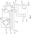
- Fig. 4 shows inner wiring of a charging cable 100 between the vehicle connection 120 and the network connection 110.
- the network connection 110 has a first network contact 131, a second network contact 132 and a first protective earth conductor contact 140.
- the vehicle connection 120 has a first supply contact 171 and a second supply contact 172 and also a second protective earth conductor contact 160.
- the first supply contact 171 and the second supply contact 172 are connected to a vehicle battery 210 of an electric vehicle 200, the vehicle battery 210 and the electric vehicle 200 not being part of the charging cable 100.
- the electric vehicle 200 is coupled capacitively and resistively to earth 230 via a vehicle impedance 220 via the second protective earth conductor contact 160.
- the second protective earth conductor contact 160 can, in this case, be connected to metal parts of the electric vehicle 200.
- the capacitive coupling then arises from the capacitance between these metal parts and the substrate, while the resistive coupling can take place via the tyres.
- the charging cable 100 has a control unit 150.
- a network rectifier 180 here consisting of a bridge circuit of four diodes.
- a direct-current voltage can be provided for the control unit 150.
- the network rectifier 180 can receive further components, for example a transformer and/or a capacitor for smoothing the direct-current voltage produced, these components not being depicted in Fig. 4 , but being known to the person skilled in the art in relation to the production of a direct-current voltage for an electronic control system from an alternating-current voltage.
- the control unit 150 is set up to ascertain a resistance between the first protective earth conductor contact 140 and the first network contact 131.
- control unit 150 is set up to compare the ascertained resistance between the first protective earth conductor contact 140 and the first network contact 131 to a predefined value.
- the electronic control system is connected to a switch 190 via a control conducting component 151.
- the switch 190 is connected to the first network contact 131 and to the second network contact 132 and also to the first supply contact 171 and to the second supply contact 172.
- the charging of the electric vehicle 200 can be enabled by means of the switch 190, by the first network contact being connected to the first supply contact and the second network contact being connected to the second supply contact. This can take place by switching on the conductivity of one or both of the two connections, in the first case the second connection being performed in a continuously guided and non-switchable manner.
- the charging cable 100 is connected to a TN or TT network
- the first protective earth conductor contact 140 is electrically conductively connected to the first network contact 131, which in this case is designed as a neutral conductor.
- the connection between the first protective earth conductor contact 140 and the first network contact 131 takes place via earth and the earthing of the power source.
- only a low resistance is measured between the first protective earth conductor contact 140 and the first network contact 131, the resistance ideally being 0 ohm in the case of perfect earthing and it also being possible for low resistances to still lead to a sufficient protective earthing.
- the predetermined value can be 1.6 kiloohms, for example, as a sufficient earthing can still be expected between the first protective earth conductor contact and the first network contact in the case of a resistance of 1.6 kiloohms.
- the electric vehicle 200 is connected to a TN or TT network with an intact protective earthing.
- the charging process can be enabled via the switch 190.
- the first network contact 131 and the second network contact 132 are each laid on an outer conductor of the IT network.
- the first protective earth conductor contact 140 is not connected to the first network contact 131, as the latter is guided from a non-earthed power source directly to the first network contact 131 without interposed earthing.
- the resistance between the first network contact 131 and the first protective earth conductor contact 140 is infinitely large, such that the switch 190 initially should not be switched and thus the charging of the electric vehicle 200 should be enabled.
- the control unit 150 is connected to the second protective earth conductor contact 160 via a signal contact 152.
- the control unit 150 is set up to apply a time-variable voltage to the second protective earth conductor contact 160 via the signal contact 152.
- This time-variable voltage is coupled into earth 230 via the vehicle impedance 220.
- the control unit 150 is set up to ascertain this signal at the first network contact and, should such a signal be ascertained, to set the switch 190 to non-conductive via the control conducting component 151. If, however, the charging cable 100 and thus the electric vehicle 200 is connected to an IT network, the first network contact 131 is thus separated galvanically from earth 230, and the signal outputted to earth 230 via the vehicle impedance 220 cannot be tapped off at the first network contact 131. In this case, the control unit 150 is set up likewise to set the switch 190 to conductive, since as a result of the absence of the time-variable signal the connection of the charging cable 100 and the electric vehicle 200 to an IT network was detected, and in the latter the enabling of the charging process is safe.
- the control unit 150 can be configured as an electronic control system.
- Fig. 4 depicts an optional signal generator 153, by which the time-variable voltage can be produced, which is then applied to the signal contact 152 and thus to the second protective earth conductor contact 160.
- control unit 150 and/or the signal generator 153 is set up to produce the time-variable voltage from the pulsating direct-current voltage produced by the network rectifier 180.
- the switch 190 is a relay.
- the switch 190 can also be designed as a high-performance MOSFET, as a high-performance diode or as a semiconductor switch of different design.
- the time-variable voltage has a frequency and the control unit 150 is set up to filter the signal tapped off at the first network contact 131 in accordance with this frequency.
- the signal yield can be increased considerably.
Landscapes
- Engineering & Computer Science (AREA)
- Power Engineering (AREA)
- Transportation (AREA)
- Mechanical Engineering (AREA)
- Physics & Mathematics (AREA)
- General Physics & Mathematics (AREA)
- Charge And Discharge Circuits For Batteries Or The Like (AREA)
- Electric Propulsion And Braking For Vehicles (AREA)
Claims (9)
- Verfahren zum Steuern eines Ladeprozesses eines Elektrofahrzeugs (200) mit den folgenden Schritten, ausgeführt durch eine Steuereinheit (150) eines Ladekabels (100):- Bestimmen eines Widerstandes zwischen einem ersten und/oder einem zweiten Netzwerkkontakt (131, 132) und einem ersten Erdungs-Schutzleiterkontakt (140) eines Netzwerkanschlusses (110) des Ladekabels (100) ;- Vergleichen des bestimmten Widerstandes mit einem vorbestimmten Wert;- Anlegen einer zeitlich veränderlichen Spannung an einen zweiten Erdungs-Schutzleiterkontakt (160) eines Fahrzeuganschlusses (120) des Ladekabels (100) ;gekennzeichnet durch folgende Schritte:- Prüfen, ob an dem ersten Netzwerkkontakt (131) und/oder an dem zweiten Netzwerkkontakt (132) des Netzwerkanschlusses (110) ein zeitlich veränderliches Signal, ausgelöst durch das Anlegen der zeitlich veränderlichen Spannung an den Fahrzeuganschluss (120), erkannt werden kann;- Ermöglichen eines Ladeprozesses, wenn entweder der bestimmte Widerstand unter dem vorbestimmten Wert liegt oder der bestimmte Widerstand über dem vorbestimmten Wert liegt und gleichzeitig kein zeitlich veränderliches Signal an dem Netzwerkanschluss (110) erkannt werden kann.
- Verfahren nach Anspruch 1, wobei die zeitlich veränderliche Spannung mit Mitteln eines Signalgenerators (153) erzeugt wird.
- Verfahren nach einem der Ansprüche 1 oder 2, wobei die zeitlich veränderliche Spannung eine pulsierende Gleichspannung aus einem Netzwerk-Gleichrichter (180) ist.
- Verfahren nach einem der Ansprüche 1 bis 3, wobei das Ermöglichen des Ladeprozesses durch das Schalten eines Relais erfolgt.
- Verfahren nach einem der Ansprüche 1 bis 4, wobei die zeitlich veränderliche Spannung eine Frequenz hat und wobei bei Erkennung an dem Netzwerkanschluss (110) eine Filterung in Übereinstimmung mit der Frequenz durchgeführt wird.
- Ladekabel (100) für ein Elektrofahrzeug (200) mit einem Netzwerkanschluss (110) und einem Fahrzeuganschluss (120), wobei der Netzwerkanschluss (110) einen ersten Erdungs-Schutzleiterkontakt (140), einen ersten Netzwerkkontakt (131) und einen zweiten Netzwerkkontakt (132) aufweist, wobei der Fahrzeuganschluss (120) einen zweiten Erdungs-Schutzleiterkontakt (160) und einen ersten Versorgungskontakt (171) und einen zweiten Versorgungskontakt (172) aufweist, wobei das Ladekabel (100) eine Steuereinheit (150) aufweist, wobei die Steuereinheit (150) eingerichtet ist, einen Widerstand zwischen einem der Netzwerkkontakte (131, 132) und dem ersten Erdungs-Schutzleiterkontakt (140) des Ladekabels (100) zu bestimmen, um den bestimmten Widerstand mit einem vorbestimmten Wert zu vergleichen, dadurch gekennzeichnet, dass die Steuereinheit (150) eingerichtet ist, eine zeitlich veränderliche Spannung an den zweiten Erdungs-Schutzleiterkontakt (160) des Fahrzeuganschlusses (120) des Ladekabels (100) anzulegen, um ein zeitlich veränderliches Signal am ersten Netzwerkkontakt (131) des ersten Netzwerkkontakts (131) und/oder am zweiten Netzwerkkontakt (132) zu erkennen, und wobei die Steuereinheit (150) eingerichtet ist, einen Ladeprozess zu ermöglichen, wenn entweder der bestimmte Widerstand unter dem vorbestimmten Wert liegt oder der bestimmte Widerstand über dem vorbestimmten Wert liegt und gleichzeitig kein zeitlich veränderliches Signal an dem Netzwerkanschluss (110) erkannt werden kann.
- Ladekabel (100) nach Anspruch 6, ferner mit einem Signalgenerator (153), wobei der Signalgenerator (153) eingerichtet ist, die zeitlich veränderliche Spannung zu erzeugen.
- Ladekabel (100) nach Anspruch 6 oder 7, ferner mit einem Netzwerk-Gleichrichter (180), wobei der Netzwerk-Gleichrichter (180) zwischen dem ersten Netzwerkkontakt (131) und dem zweiten Netzwerkkontakt (132) angeordnet ist, wobei der Netzwerk-Gleichrichter (180) eine Versorgungsspannung für die Steuereinheit (150) ausgibt, wobei die zeitlich veränderliche Spannung eine pulsierende Gleichspannung ist.
- Ladekabel (100) nach einem der Ansprüche 6 bis 8, ferner mit einem Relais (190) zwischen den Netzwerkkontakten (131, 132) und den Versorgungskontakten (171, 172), wobei das Ermöglichen des Ladeprozesses über ein Schalten des Relais (190) erfolgt.
Applications Claiming Priority (1)
| Application Number | Priority Date | Filing Date | Title |
|---|---|---|---|
| DE102018111536.9A DE102018111536B3 (de) | 2018-05-15 | 2018-05-15 | Verfahren zur Steuerung eines Ladevorgangs eines Elektrofahrzeugs und Ladekabel |
Publications (2)
| Publication Number | Publication Date |
|---|---|
| EP3569441A1 EP3569441A1 (de) | 2019-11-20 |
| EP3569441B1 true EP3569441B1 (de) | 2024-12-04 |
Family
ID=66476464
Family Applications (1)
| Application Number | Title | Priority Date | Filing Date |
|---|---|---|---|
| EP19173455.7A Active EP3569441B1 (de) | 2018-05-15 | 2019-05-09 | Verfahren zur steuerung eines ladevorgangs eines elektrofahrzeugs und ladekabel |
Country Status (3)
| Country | Link |
|---|---|
| EP (1) | EP3569441B1 (de) |
| CN (1) | CN110488111B (de) |
| DE (1) | DE102018111536B3 (de) |
Families Citing this family (2)
| Publication number | Priority date | Publication date | Assignee | Title |
|---|---|---|---|---|
| CN113394989B (zh) * | 2020-03-12 | 2023-08-08 | Oppo广东移动通信有限公司 | 电源转换装置及充电控制方法 |
| US12571824B2 (en) | 2024-01-19 | 2026-03-10 | HELLA GmbH & Co. KGaA | Method and system for monitoring impedance in a conductor |
Family Cites Families (11)
| Publication number | Priority date | Publication date | Assignee | Title |
|---|---|---|---|---|
| DE19746200C2 (de) * | 1997-10-18 | 2001-06-28 | Beha C Gmbh | Verfahren zur Bestimmung des Schleifenwiderstands eines Stromversorgungsnetzes |
| JP4561878B2 (ja) * | 2008-06-05 | 2010-10-13 | トヨタ自動車株式会社 | 蓄電装置を搭載する車両および充電ケーブル |
| DE102011107628A1 (de) | 2011-06-30 | 2013-01-03 | Rwe Ag | Ladevorrichtung für elektrofahrzeuge und verfahren zum laden von elektrofahrzeugen |
| FR2978556B1 (fr) * | 2011-07-29 | 2014-03-07 | Schneider Electric Ind Sas | Dispositif de surveillance d'un conducteur de terre avec mesure de l'impedance |
| FR3007844B1 (fr) * | 2013-06-26 | 2015-07-17 | Schneider Electric Ind Sas | Dispositif d'estimation de l'impedance d'une liaison electrique de terre, procede d'estimation et systeme d'alimentation electrique associes |
| DE102013212221A1 (de) | 2013-06-26 | 2014-12-31 | Bayerische Motorenwerke Aktiengesellschaft | Ladeanschlusserkennung |
| NO337360B1 (no) * | 2014-03-11 | 2016-03-29 | Zaptec Ip As | Strømforsyningssystem for lading av elektriske kjøretøy |
| DE102014004791B3 (de) * | 2014-04-02 | 2015-08-06 | Audi Ag | Verfahren zur Überprüfung einer Verbindung zwischen einem Niedrigspannungsnetz und einer Batterie und Kraftfahrzeug |
| JP2015211547A (ja) * | 2014-04-25 | 2015-11-24 | トヨタ自動車株式会社 | 充電システム |
| DE102015206047A1 (de) | 2015-04-02 | 2016-10-06 | Volkswagen Aktiengesellschaft | Adapter für ein Ladestecksystem |
| CN105720602B (zh) * | 2016-01-21 | 2019-02-05 | 易事特集团股份有限公司 | 光伏并网发电储能逆变器并网-离网系统及其运行装置 |
-
2018
- 2018-05-15 DE DE102018111536.9A patent/DE102018111536B3/de active Active
-
2019
- 2019-05-09 EP EP19173455.7A patent/EP3569441B1/de active Active
- 2019-05-15 CN CN201910403346.9A patent/CN110488111B/zh active Active
Also Published As
| Publication number | Publication date |
|---|---|
| CN110488111B (zh) | 2024-11-29 |
| EP3569441A1 (de) | 2019-11-20 |
| CN110488111A (zh) | 2019-11-22 |
| DE102018111536B3 (de) | 2019-09-19 |
Similar Documents
| Publication | Publication Date | Title |
|---|---|---|
| JP5369833B2 (ja) | 電動車両用充電器および地絡検出方法 | |
| US10161982B2 (en) | Failure inspection system enabling discrimination between leakage current failure and short-circuit failure | |
| US10682916B2 (en) | Thermal management of electric vehicle coupler contacts | |
| US20140347769A1 (en) | Electric-vehicular charge and discharge device | |
| EP3572271B1 (de) | Elektrofahrzeugladesystem zum laden eines elektrofahrzeugs | |
| EP2645512B1 (de) | Erkennungssystem und -verfahren für einen defekten Schutzleiter-Massestromkreis | |
| CN111051901B (zh) | 用于监控电源的源电压和绝缘电阻的监控设备、高压系统以及用于操作监控设备的方法 | |
| CN112467719B (zh) | 用于补偿漏电流的补偿装置 | |
| EP3572270B1 (de) | Gleichstromladekabel und verfahren zur bestimmung einer temperatur des gleichstromladekabels | |
| CN110871695A (zh) | 用于控制车辆外部的充电设备的方法和充电设备 | |
| CN114599545B (zh) | 用于防止插座接触器同时闭合的电动车辆充电系统 | |
| US11465525B2 (en) | Measuring apparatus and method for capturing electrical energy transferred from a charging station | |
| US11404999B2 (en) | Method for detecting a contact fault in a photovoltaic system | |
| CN109387700B (zh) | 用于充电电缆中的接地电阻识别的方法和设备 | |
| US20180361862A1 (en) | Vehicle charge-cord system | |
| US12083900B2 (en) | Control unit circuit for a motor vehicle, motor vehicle and operating method for the control unit circuit | |
| EP3569441B1 (de) | Verfahren zur steuerung eines ladevorgangs eines elektrofahrzeugs und ladekabel | |
| JP6956782B2 (ja) | 監視デバイスおよび保護導体のインピーダンスを監視する方法、ならびに充電制御ユニット | |
| CN103180160A (zh) | 用于估计触摸电流并且保护电气装置免受这种触摸电流的设备和方法 | |
| CN112285577B (zh) | 检测装置 | |
| US20250147093A1 (en) | Sensing symmetrical and asymmetrical insulation faults by the asymmetrically switchable sensing of fault current | |
| US20260034949A1 (en) | Bidirectional on-board charger of a vehicle and method for diagnosing a function of a relay which the on-board charger comprises | |
| CN112105523A (zh) | 运行充电设备的方法和对电动车的储能器充电的充电设备 | |
| JP4541034B2 (ja) | 電路の接地監視装置 | |
| TW535274B (en) | Integrated circuit having a backup capacitance |
Legal Events
| Date | Code | Title | Description |
|---|---|---|---|
| PUAI | Public reference made under article 153(3) epc to a published international application that has entered the european phase |
Free format text: ORIGINAL CODE: 0009012 |
|
| STAA | Information on the status of an ep patent application or granted ep patent |
Free format text: STATUS: THE APPLICATION HAS BEEN PUBLISHED |
|
| AK | Designated contracting states |
Kind code of ref document: A1 Designated state(s): AL AT BE BG CH CY CZ DE DK EE ES FI FR GB GR HR HU IE IS IT LI LT LU LV MC MK MT NL NO PL PT RO RS SE SI SK SM TR |
|
| AX | Request for extension of the european patent |
Extension state: BA ME |
|
| STAA | Information on the status of an ep patent application or granted ep patent |
Free format text: STATUS: REQUEST FOR EXAMINATION WAS MADE |
|
| 17P | Request for examination filed |
Effective date: 20200326 |
|
| RBV | Designated contracting states (corrected) |
Designated state(s): AL AT BE BG CH CY CZ DE DK EE ES FI FR GB GR HR HU IE IS IT LI LT LU LV MC MK MT NL NO PL PT RO RS SE SI SK SM TR |
|
| STAA | Information on the status of an ep patent application or granted ep patent |
Free format text: STATUS: EXAMINATION IS IN PROGRESS |
|
| 17Q | First examination report despatched |
Effective date: 20211117 |
|
| GRAP | Despatch of communication of intention to grant a patent |
Free format text: ORIGINAL CODE: EPIDOSNIGR1 |
|
| STAA | Information on the status of an ep patent application or granted ep patent |
Free format text: STATUS: GRANT OF PATENT IS INTENDED |
|
| INTG | Intention to grant announced |
Effective date: 20240315 |
|
| GRAJ | Information related to disapproval of communication of intention to grant by the applicant or resumption of examination proceedings by the epo deleted |
Free format text: ORIGINAL CODE: EPIDOSDIGR1 |
|
| STAA | Information on the status of an ep patent application or granted ep patent |
Free format text: STATUS: EXAMINATION IS IN PROGRESS |
|
| GRAP | Despatch of communication of intention to grant a patent |
Free format text: ORIGINAL CODE: EPIDOSNIGR1 |
|
| STAA | Information on the status of an ep patent application or granted ep patent |
Free format text: STATUS: GRANT OF PATENT IS INTENDED |
|
| INTC | Intention to grant announced (deleted) | ||
| INTG | Intention to grant announced |
Effective date: 20240626 |
|
| GRAS | Grant fee paid |
Free format text: ORIGINAL CODE: EPIDOSNIGR3 |
|
| GRAA | (expected) grant |
Free format text: ORIGINAL CODE: 0009210 |
|
| STAA | Information on the status of an ep patent application or granted ep patent |
Free format text: STATUS: THE PATENT HAS BEEN GRANTED |
|
| AK | Designated contracting states |
Kind code of ref document: B1 Designated state(s): AL AT BE BG CH CY CZ DE DK EE ES FI FR GB GR HR HU IE IS IT LI LT LU LV MC MK MT NL NO PL PT RO RS SE SI SK SM TR |
|
| REG | Reference to a national code |
Ref country code: GB Ref legal event code: FG4D |
|
| REG | Reference to a national code |
Ref country code: CH Ref legal event code: EP |
|
| REG | Reference to a national code |
Ref country code: DE Ref legal event code: R096 Ref document number: 602019062857 Country of ref document: DE |
|
| REG | Reference to a national code |
Ref country code: IE Ref legal event code: FG4D |
|
| REG | Reference to a national code |
Ref country code: LT Ref legal event code: MG9D |
|
| REG | Reference to a national code |
Ref country code: NL Ref legal event code: MP Effective date: 20241204 |
|
| PG25 | Lapsed in a contracting state [announced via postgrant information from national office to epo] |
Ref country code: HR Free format text: LAPSE BECAUSE OF FAILURE TO SUBMIT A TRANSLATION OF THE DESCRIPTION OR TO PAY THE FEE WITHIN THE PRESCRIBED TIME-LIMIT Effective date: 20241204 |
|
| PG25 | Lapsed in a contracting state [announced via postgrant information from national office to epo] |
Ref country code: FI Free format text: LAPSE BECAUSE OF FAILURE TO SUBMIT A TRANSLATION OF THE DESCRIPTION OR TO PAY THE FEE WITHIN THE PRESCRIBED TIME-LIMIT Effective date: 20241204 |
|
| PG25 | Lapsed in a contracting state [announced via postgrant information from national office to epo] |
Ref country code: BG Free format text: LAPSE BECAUSE OF FAILURE TO SUBMIT A TRANSLATION OF THE DESCRIPTION OR TO PAY THE FEE WITHIN THE PRESCRIBED TIME-LIMIT Effective date: 20241204 |
|
| PG25 | Lapsed in a contracting state [announced via postgrant information from national office to epo] |
Ref country code: ES Free format text: LAPSE BECAUSE OF FAILURE TO SUBMIT A TRANSLATION OF THE DESCRIPTION OR TO PAY THE FEE WITHIN THE PRESCRIBED TIME-LIMIT Effective date: 20241204 |
|
| PG25 | Lapsed in a contracting state [announced via postgrant information from national office to epo] |
Ref country code: NO Free format text: LAPSE BECAUSE OF FAILURE TO SUBMIT A TRANSLATION OF THE DESCRIPTION OR TO PAY THE FEE WITHIN THE PRESCRIBED TIME-LIMIT Effective date: 20250304 |
|
| PG25 | Lapsed in a contracting state [announced via postgrant information from national office to epo] |
Ref country code: LV Free format text: LAPSE BECAUSE OF FAILURE TO SUBMIT A TRANSLATION OF THE DESCRIPTION OR TO PAY THE FEE WITHIN THE PRESCRIBED TIME-LIMIT Effective date: 20241204 Ref country code: GR Free format text: LAPSE BECAUSE OF FAILURE TO SUBMIT A TRANSLATION OF THE DESCRIPTION OR TO PAY THE FEE WITHIN THE PRESCRIBED TIME-LIMIT Effective date: 20250305 |
|
| PG25 | Lapsed in a contracting state [announced via postgrant information from national office to epo] |
Ref country code: RS Free format text: LAPSE BECAUSE OF FAILURE TO SUBMIT A TRANSLATION OF THE DESCRIPTION OR TO PAY THE FEE WITHIN THE PRESCRIBED TIME-LIMIT Effective date: 20250304 |
|
| PG25 | Lapsed in a contracting state [announced via postgrant information from national office to epo] |
Ref country code: NL Free format text: LAPSE BECAUSE OF FAILURE TO SUBMIT A TRANSLATION OF THE DESCRIPTION OR TO PAY THE FEE WITHIN THE PRESCRIBED TIME-LIMIT Effective date: 20241204 |
|
| REG | Reference to a national code |
Ref country code: AT Ref legal event code: MK05 Ref document number: 1747838 Country of ref document: AT Kind code of ref document: T Effective date: 20241204 |
|
| PG25 | Lapsed in a contracting state [announced via postgrant information from national office to epo] |
Ref country code: SM Free format text: LAPSE BECAUSE OF FAILURE TO SUBMIT A TRANSLATION OF THE DESCRIPTION OR TO PAY THE FEE WITHIN THE PRESCRIBED TIME-LIMIT Effective date: 20241204 |
|
| PG25 | Lapsed in a contracting state [announced via postgrant information from national office to epo] |
Ref country code: PL Free format text: LAPSE BECAUSE OF FAILURE TO SUBMIT A TRANSLATION OF THE DESCRIPTION OR TO PAY THE FEE WITHIN THE PRESCRIBED TIME-LIMIT Effective date: 20241204 |
|
| PGFP | Annual fee paid to national office [announced via postgrant information from national office to epo] |
Ref country code: DE Payment date: 20250311 Year of fee payment: 7 |
|
| PG25 | Lapsed in a contracting state [announced via postgrant information from national office to epo] |
Ref country code: IS Free format text: LAPSE BECAUSE OF FAILURE TO SUBMIT A TRANSLATION OF THE DESCRIPTION OR TO PAY THE FEE WITHIN THE PRESCRIBED TIME-LIMIT Effective date: 20250404 |
|
| PG25 | Lapsed in a contracting state [announced via postgrant information from national office to epo] |
Ref country code: PT Free format text: LAPSE BECAUSE OF FAILURE TO SUBMIT A TRANSLATION OF THE DESCRIPTION OR TO PAY THE FEE WITHIN THE PRESCRIBED TIME-LIMIT Effective date: 20250404 |
|
| PG25 | Lapsed in a contracting state [announced via postgrant information from national office to epo] |
Ref country code: EE Free format text: LAPSE BECAUSE OF FAILURE TO SUBMIT A TRANSLATION OF THE DESCRIPTION OR TO PAY THE FEE WITHIN THE PRESCRIBED TIME-LIMIT Effective date: 20241204 |
|
| PG25 | Lapsed in a contracting state [announced via postgrant information from national office to epo] |
Ref country code: RO Free format text: LAPSE BECAUSE OF FAILURE TO SUBMIT A TRANSLATION OF THE DESCRIPTION OR TO PAY THE FEE WITHIN THE PRESCRIBED TIME-LIMIT Effective date: 20241204 Ref country code: AT Free format text: LAPSE BECAUSE OF FAILURE TO SUBMIT A TRANSLATION OF THE DESCRIPTION OR TO PAY THE FEE WITHIN THE PRESCRIBED TIME-LIMIT Effective date: 20241204 |
|
| PG25 | Lapsed in a contracting state [announced via postgrant information from national office to epo] |
Ref country code: SK Free format text: LAPSE BECAUSE OF FAILURE TO SUBMIT A TRANSLATION OF THE DESCRIPTION OR TO PAY THE FEE WITHIN THE PRESCRIBED TIME-LIMIT Effective date: 20241204 |
|
| PG25 | Lapsed in a contracting state [announced via postgrant information from national office to epo] |
Ref country code: CZ Free format text: LAPSE BECAUSE OF FAILURE TO SUBMIT A TRANSLATION OF THE DESCRIPTION OR TO PAY THE FEE WITHIN THE PRESCRIBED TIME-LIMIT Effective date: 20241204 |
|
| PG25 | Lapsed in a contracting state [announced via postgrant information from national office to epo] |
Ref country code: IT Free format text: LAPSE BECAUSE OF FAILURE TO SUBMIT A TRANSLATION OF THE DESCRIPTION OR TO PAY THE FEE WITHIN THE PRESCRIBED TIME-LIMIT Effective date: 20241204 |
|
| REG | Reference to a national code |
Ref country code: DE Ref legal event code: R097 Ref document number: 602019062857 Country of ref document: DE |
|
| PG25 | Lapsed in a contracting state [announced via postgrant information from national office to epo] |
Ref country code: SE Free format text: LAPSE BECAUSE OF FAILURE TO SUBMIT A TRANSLATION OF THE DESCRIPTION OR TO PAY THE FEE WITHIN THE PRESCRIBED TIME-LIMIT Effective date: 20241204 |
|
| PG25 | Lapsed in a contracting state [announced via postgrant information from national office to epo] |
Ref country code: DK Free format text: LAPSE BECAUSE OF FAILURE TO SUBMIT A TRANSLATION OF THE DESCRIPTION OR TO PAY THE FEE WITHIN THE PRESCRIBED TIME-LIMIT Effective date: 20241204 |
|
| PLBE | No opposition filed within time limit |
Free format text: ORIGINAL CODE: 0009261 |
|
| STAA | Information on the status of an ep patent application or granted ep patent |
Free format text: STATUS: NO OPPOSITION FILED WITHIN TIME LIMIT |
|
| REG | Reference to a national code |
Ref country code: CH Ref legal event code: L10 Free format text: ST27 STATUS EVENT CODE: U-0-0-L10-L00 (AS PROVIDED BY THE NATIONAL OFFICE) Effective date: 20251015 |
|
| 26N | No opposition filed |
Effective date: 20250905 |
|
| REG | Reference to a national code |
Ref country code: CH Ref legal event code: H13 Free format text: ST27 STATUS EVENT CODE: U-0-0-H10-H13 (AS PROVIDED BY THE NATIONAL OFFICE) Effective date: 20251223 |
|
| PG25 | Lapsed in a contracting state [announced via postgrant information from national office to epo] |
Ref country code: LU Free format text: LAPSE BECAUSE OF NON-PAYMENT OF DUE FEES Effective date: 20250509 |
|
| PG25 | Lapsed in a contracting state [announced via postgrant information from national office to epo] |
Ref country code: CH Free format text: LAPSE BECAUSE OF NON-PAYMENT OF DUE FEES Effective date: 20250531 |
|
| GBPC | Gb: european patent ceased through non-payment of renewal fee |
Effective date: 20250509 |
|
| REG | Reference to a national code |
Ref country code: BE Ref legal event code: MM Effective date: 20250531 |
|
| PG25 | Lapsed in a contracting state [announced via postgrant information from national office to epo] |
Ref country code: MC Free format text: LAPSE BECAUSE OF FAILURE TO SUBMIT A TRANSLATION OF THE DESCRIPTION OR TO PAY THE FEE WITHIN THE PRESCRIBED TIME-LIMIT Effective date: 20241204 |
|
| PG25 | Lapsed in a contracting state [announced via postgrant information from national office to epo] |
Ref country code: GB Free format text: LAPSE BECAUSE OF NON-PAYMENT OF DUE FEES Effective date: 20250509 |
|
| PG25 | Lapsed in a contracting state [announced via postgrant information from national office to epo] |
Ref country code: IE Free format text: LAPSE BECAUSE OF NON-PAYMENT OF DUE FEES Effective date: 20250509 |
|
| PG25 | Lapsed in a contracting state [announced via postgrant information from national office to epo] |
Ref country code: BE Free format text: LAPSE BECAUSE OF NON-PAYMENT OF DUE FEES Effective date: 20250531 |
|
| PG25 | Lapsed in a contracting state [announced via postgrant information from national office to epo] |
Ref country code: FR Free format text: LAPSE BECAUSE OF NON-PAYMENT OF DUE FEES Effective date: 20250531 |