EP3569365A1 - Dust collecting device and electric tool - Google Patents
Dust collecting device and electric tool Download PDFInfo
- Publication number
- EP3569365A1 EP3569365A1 EP18777842.8A EP18777842A EP3569365A1 EP 3569365 A1 EP3569365 A1 EP 3569365A1 EP 18777842 A EP18777842 A EP 18777842A EP 3569365 A1 EP3569365 A1 EP 3569365A1
- Authority
- EP
- European Patent Office
- Prior art keywords
- pipe
- straight line
- housing portion
- housing
- collection device
- Prior art date
- Legal status (The legal status is an assumption and is not a legal conclusion. Google has not performed a legal analysis and makes no representation as to the accuracy of the status listed.)
- Granted
Links
Images




Classifications
-
- B—PERFORMING OPERATIONS; TRANSPORTING
- B24—GRINDING; POLISHING
- B24B—MACHINES, DEVICES, OR PROCESSES FOR GRINDING OR POLISHING; DRESSING OR CONDITIONING OF ABRADING SURFACES; FEEDING OF GRINDING, POLISHING, OR LAPPING AGENTS
- B24B55/00—Safety devices for grinding or polishing machines; Accessories fitted to grinding or polishing machines for keeping tools or parts of the machine in good working condition
- B24B55/06—Dust extraction equipment on grinding or polishing machines
- B24B55/10—Dust extraction equipment on grinding or polishing machines specially designed for portable grinding machines, e.g. hand-guided
-
- B—PERFORMING OPERATIONS; TRANSPORTING
- B25—HAND TOOLS; PORTABLE POWER-DRIVEN TOOLS; MANIPULATORS
- B25F—COMBINATION OR MULTI-PURPOSE TOOLS NOT OTHERWISE PROVIDED FOR; DETAILS OR COMPONENTS OF PORTABLE POWER-DRIVEN TOOLS NOT PARTICULARLY RELATED TO THE OPERATIONS PERFORMED AND NOT OTHERWISE PROVIDED FOR
- B25F5/00—Details or components of portable power-driven tools not particularly related to the operations performed and not otherwise provided for
-
- B—PERFORMING OPERATIONS; TRANSPORTING
- B24—GRINDING; POLISHING
- B24B—MACHINES, DEVICES, OR PROCESSES FOR GRINDING OR POLISHING; DRESSING OR CONDITIONING OF ABRADING SURFACES; FEEDING OF GRINDING, POLISHING, OR LAPPING AGENTS
- B24B55/00—Safety devices for grinding or polishing machines; Accessories fitted to grinding or polishing machines for keeping tools or parts of the machine in good working condition
- B24B55/06—Dust extraction equipment on grinding or polishing machines
- B24B55/10—Dust extraction equipment on grinding or polishing machines specially designed for portable grinding machines, e.g. hand-guided
- B24B55/102—Dust extraction equipment on grinding or polishing machines specially designed for portable grinding machines, e.g. hand-guided with rotating tools
-
- B—PERFORMING OPERATIONS; TRANSPORTING
- B23—MACHINE TOOLS; METAL-WORKING NOT OTHERWISE PROVIDED FOR
- B23Q—DETAILS, COMPONENTS, OR ACCESSORIES FOR MACHINE TOOLS, e.g. ARRANGEMENTS FOR COPYING OR CONTROLLING; MACHINE TOOLS IN GENERAL CHARACTERISED BY THE CONSTRUCTION OF PARTICULAR DETAILS OR COMPONENTS; COMBINATIONS OR ASSOCIATIONS OF METAL-WORKING MACHINES, NOT DIRECTED TO A PARTICULAR RESULT
- B23Q11/00—Accessories fitted to machine tools for keeping tools or parts of the machine in good working condition or for cooling work; Safety devices specially combined with or arranged in, or specially adapted for use in connection with, machine tools
- B23Q11/0042—Devices for removing chips
- B23Q11/0046—Devices for removing chips by sucking
-
- B—PERFORMING OPERATIONS; TRANSPORTING
- B23—MACHINE TOOLS; METAL-WORKING NOT OTHERWISE PROVIDED FOR
- B23Q—DETAILS, COMPONENTS, OR ACCESSORIES FOR MACHINE TOOLS, e.g. ARRANGEMENTS FOR COPYING OR CONTROLLING; MACHINE TOOLS IN GENERAL CHARACTERISED BY THE CONSTRUCTION OF PARTICULAR DETAILS OR COMPONENTS; COMBINATIONS OR ASSOCIATIONS OF METAL-WORKING MACHINES, NOT DIRECTED TO A PARTICULAR RESULT
- B23Q11/00—Accessories fitted to machine tools for keeping tools or parts of the machine in good working condition or for cooling work; Safety devices specially combined with or arranged in, or specially adapted for use in connection with, machine tools
- B23Q11/0042—Devices for removing chips
- B23Q11/0071—Devices for removing chips dust collectors for hand tools
-
- B—PERFORMING OPERATIONS; TRANSPORTING
- B24—GRINDING; POLISHING
- B24B—MACHINES, DEVICES, OR PROCESSES FOR GRINDING OR POLISHING; DRESSING OR CONDITIONING OF ABRADING SURFACES; FEEDING OF GRINDING, POLISHING, OR LAPPING AGENTS
- B24B23/00—Portable grinding machines, e.g. hand-guided; Accessories therefor
-
- B—PERFORMING OPERATIONS; TRANSPORTING
- B24—GRINDING; POLISHING
- B24B—MACHINES, DEVICES, OR PROCESSES FOR GRINDING OR POLISHING; DRESSING OR CONDITIONING OF ABRADING SURFACES; FEEDING OF GRINDING, POLISHING, OR LAPPING AGENTS
- B24B23/00—Portable grinding machines, e.g. hand-guided; Accessories therefor
- B24B23/005—Auxiliary devices used in connection with portable grinding machines, e.g. holders
-
- B—PERFORMING OPERATIONS; TRANSPORTING
- B24—GRINDING; POLISHING
- B24B—MACHINES, DEVICES, OR PROCESSES FOR GRINDING OR POLISHING; DRESSING OR CONDITIONING OF ABRADING SURFACES; FEEDING OF GRINDING, POLISHING, OR LAPPING AGENTS
- B24B23/00—Portable grinding machines, e.g. hand-guided; Accessories therefor
- B24B23/02—Portable grinding machines, e.g. hand-guided; Accessories therefor with rotating grinding tools; Accessories therefor
- B24B23/028—Angle tools
-
- B—PERFORMING OPERATIONS; TRANSPORTING
- B25—HAND TOOLS; PORTABLE POWER-DRIVEN TOOLS; MANIPULATORS
- B25F—COMBINATION OR MULTI-PURPOSE TOOLS NOT OTHERWISE PROVIDED FOR; DETAILS OR COMPONENTS OF PORTABLE POWER-DRIVEN TOOLS NOT PARTICULARLY RELATED TO THE OPERATIONS PERFORMED AND NOT OTHERWISE PROVIDED FOR
- B25F5/00—Details or components of portable power-driven tools not particularly related to the operations performed and not otherwise provided for
- B25F5/02—Construction of casings, bodies or handles
Definitions
- the present disclosure relates to a power tool, and in particular, relates to a dust collection device.
- an object of the present disclosure is to provide a dust collection device which offers a high dust collecting efficiency and a superior dust separation effect.
- the present disclosure adopts the following technical solution.
- a dust collection device including: a housing, defining an accommodating chamber for collecting a dust; an air inlet pipe, configured to guide an airflow to enter the dust collection device along a first straight line; a cyclone pipe, extending along a second straight line, and comprising a first end for the air intake and a second end for the dust discharge along the second straight line; an air duct pipe, defining an air duct communicating the air inlet pipe with the cyclone pipe; and a ventilation pipe, arranged at the first end of the cyclone pipe, and communicated with the cyclone pipe, the ventilation pipe being configured to guide the airflow after being subjected to dust separation performed by the cyclone pipe out of the housing; wherein the housing further defines an air outlet communicated with the ventilation pipe or through which the ventilation pipe extends out of the housing.
- the second straight line along which the cyclone pipe extends intersects the first straight line to form an angle greater than or equal to 25° and less than or equal to 90°.
- the second straight line direction along which the cyclone pipe extends and the first straight line are perpendicular to each other.
- the dust collection device further includes an air guiding portion, configured to guide the airflow from the air duct to enter the cyclone pipe substantially along a direction perpendicular to the second straight line.
- the housing includes: a first housing portion, defining the air outlet; and a second housing portion, detachably connected to the first housing portion; wherein the accommodating chamber is formed on condition that the second housing portion is joined with the first housing portion.
- the air inlet pipe, the cyclone pipe, the air duct pipe and the ventilation pipe are fixedly connected to the second housing portion.
- the air duct pipe at least partially extends along a direction obliquely intersects the second straight line.
- the air duct pipe includes a third end connected to the air inlet pipe and a fourth end connected to the cyclone pipe, the third end and the fourth end being located at two ends along an extending direction of the air duct pipe.
- the fourth end and the third end of the air duct pipe constitute a height difference.
- the housing has a length extending along the first straight line.
- the second straight line along which the cyclone pipe extends in the accommodating chamber is perpendicular to the length of the housing.
- the cyclone pipe further includes an intermediate section arranged between the first end and the second end along the second straight line.
- the intermediate section has an inner wall which has a circular cross section in a plane perpendicular to the second straight line.
- a ratio of a diameter of the circular shape formed by the cross section of the inner wall of the intermediate section in the plane perpendicular to the second straight line to a length of cyclone pipe along the second straight line is greater than or equal to 0.4 and less than or equal to 0.7.
- the diameter of the inner wall of the intermediate section is greater than or equal to 30mm and less than or equal to 60mm.
- the air inlet pipe is a cylinder-shaped pipe.
- the diameter of the inner wall of the intermediate section is greater than a diameter of an inner wall of the air inlet pipe.
- a number of the cyclone pipe is 1.
- first straight line along which the airflow enters the air inlet pipe and the second straight line along which the cyclone pipe extends are further perpendicular to each other.
- the air inlet pipe is located between the first end and the second end along a direction parallel to the second straight line.
- the housing further includes: a first housing portion, defining an air outlet communicated with the ventilation pipe or through which the ventilation pipe extends out of the housing; and a second housing portion, disposed to be detachably connected to the first housing portion; wherein the accommodating chamber is formed by the second housing portion and the first housing portion on condition that the second housing portion is joined with the first housing portion.
- the accommodating chamber is opened to form a dust pouring opening for pouring out the dust in the accommodating chamber on condition that the second housing portion and the first housing portion are detached from each other.
- the air inlet pipe, the cyclone pipe, the air duct pipe and the ventilation pipe are fixedly connected to the second housing portion, so that the air inlet pipe, the cyclone pipe, the air duct pipe and the ventilation pipe are separated from the accommodating chamber on condition that the second housing portion is detached from the first housing portion.
- the dust pouring opening is opened toward a direction in which the second housing portion is detached from the first housing portion.
- first housing portion is provided with a guiding rail for guiding the second housing portion to be joined to the first housing portion along the first straight line.
- the second housing portion is provided with a matching portion for cooperating with the guiding rail.
- the housing has a length extending along the first straight line.
- the housing comprises a front wall and a rear wall at two ends in the length of the housing.
- the rear wall is formed by the first housing portion, and the front wall is formed by the second housing portion.
- an outer side of the first housing portion is further provided with an elastic tab having a hook portion.
- the second housing portion is provided with a slot into which the hook portion is partially embedded.
- the elastic tab is configured to generate an elastic force that is operative to move the hook portion toward the slot to be embedded into the slot.
- the air inlet pipe is configured to communicate an inside and an outside of the housing.
- the air inlet pipe is fixedly connected to the second housing portion and penetrates through the second housing portion in the first straight line.
- the housing has a length extending along the first straight line and a width direction extending along the second straight line. A size of the housing in the length is greater than a size of the housing in the width direction.
- a projection of the air inlet pipe onto a plane perpendicular to the first straight line is located within a projection of the dust pouring opening onto the plane perpendicular to the first straight line.
- a power tool including a tool housing, a motor arranged inside the tool housing, and the dust collecting device described above.
- the housing includes a dust heaping plane for heaping the dust.
- dust heaping plane for heaping the dust.
- the present disclosure offers advantages of a high dust collection efficiency with the dust collection device, and more efficient dust separation.
- a power tool 1 according to the first embodiment as illustrated in FIG. 1 to FIG. 3 includes a tool main body 100 and a dust collection device 200.
- the tool main body 100 may be a grinding-type tool which may generate a large amount of dust, thus the dust collection device 200 for collecting the dust is necessary to be arranged on this kind of tools.
- the tool main body 100 may include a tool housing 11, a motor 12, and a fan 13.
- the tool housing 11 may be provided with an outlet 111 through which the dust is discharged out of the tool main body 100.
- the dust collection device 200 is connected to the outlet 111.
- the motor 12 and the fan 13 are arranged inside the tool housing 11.
- the fan 13 can generate an airflow and the dust can be discharged to the dust collection device 200 along with the airflow; or the dust collection device 200 may be connected to an external vacuum cleaner, and the dust is extracted into the dust collection device 200 through the vacuum cleaner; or the dust collection device may be self-contained with a dust extraction fan, and the dust is extracted into the dust collection device 200 through the dust extraction fan.
- the tool main body 100 and the dust collection device 200 are detachably connected, so that the user can selectively determine whether the dust collection device 200 needs to be mounted to the tool main body 100 to perform the dust extraction treatment.
- the dust collection device 200 includes a housing 20 provided with an accommodating chamber 201 for collecting dust.
- the housing 20 includes a first housing portion 21 and a second housing portion 22.
- the first housing portion 21 and the second housing portion 22 are detachably connected.
- the accommodating chamber 201 is formed between the first housing portion 21 and the second housing portion 22.
- the accommodating chamber 201 is opened to form a dust pouring opening 212 through which the dust is poured out of the accommodating chamber 201.
- the dust pouring opening 212 may be defined to be relatively large, which is favorable for pouring out the dust.
- a dust pouring opening 212 be means the detachable connection between the first housing portion 21 and the second housing portion 22, the housing 20 of the dust collection device does not need to be separately provided with an opening for pouring the dust and a door for closing the opening, so that the dust collection device 200 is simple in structure and can be easy to manufacture.
- the detachable connection in the present disclosure means that the first housing portion 21 and the second housing portion 22 can be quickly detached and mounted by the user without needing an auxiliary tool.
- the first housing portion 21 has a length extending along a first straight line 101, a width extending along a second straight line 102, and a height extending along a third straight line 103. It should be understood that a dimension of the first housing portion 21 in the length should be larger than a dimension of the first housing portion 21 in the width, and also larger than a dimension of the first housing portion 21 in the height.
- the first housing portion 21 in the length extending along the first straight line 101 includes a rear wall 211 facing away from the tool main body 100.
- a front end of the first housing portion 21 opposite to the rear wall 211 is opened forwards to form the dust pouring opening 212, thereby coupling the second housing portion 22.
- the first housing portion 21 in the width extending along the second straight line 102 includes a left wall 213 and a right wall 214.
- the first housing portion 21 in the height extending along the third straight line 103 includes an upper wall 215 and a lower wall 216.
- the opened accommodating chamber 201 with the dust pouring opening 212 is formed between the rear wall 211, the left wall 213, the right wall 214, the upper wall 215, and the lower wall 216.
- the second housing portion 22 includes a front wall 225 at least partially covering the dust pouring opening 212.
- the dust pouring opening 212 is opened towards the direction in which the second housing portion 22 is detached from the first housing portion 21.
- the second housing portion 22 may be inserted into the first housing portion 21 or be pulled out of the first housing portion 21 through the dust pouring opening 212 of the first housing portion 21 opened forward along the first straight line 101, namely, the second housing portion 22 and the first housing portion 21 are detachably connected along the first straight line 101.
- the user may pull out the second housing portion 22 from the first housing portion 21 along the first straight line 101, and then pour out the dust through the dust pouring opening 212 of the first housing portion 21 opened forward.
- An area of a projection of the dust pouring opening 212 onto a plane perpendicular to the first straight line 101 is greater than an area of a projection of the outlet onto the plane perpendicular to the first straight line 101, so that the dust pouring opening 212 is relatively large, which is favorable for pouring out the dust.
- the dust collection device 200 further includes an air inlet pipe 221, a cyclone pipe 222, an air duct pipe 223, and a ventilation pipe 224.
- the air inlet pipe 221 is configured to guide the airflow to enter the dust collection device 200 along the first straight line 101.
- the cyclone pipe 222 is configured to generate a cyclone to separate the dust from the airflow.
- the air duct pipe 223 is configured to connect the air inlet pipe 221 to the cyclone pipe 222.
- the ventilation pipe 224 is configured to communicate an inside and an outside of the cyclone pipe 222 to guide the airflow after being subjected to dust separation by the cyclone pipe 222 out of the cyclone pipe 222.
- the cyclone pipe 222 and the air duct pipe 223 are arranged inside the accommodating chamber 201, the air inlet pipe 221 is at least partially arranged inside the accommodating chamber 201, and the ventilation pipe 224 is also at least partially arranged inside the accommodating chamber 201.
- the air inlet pipe 221, the cyclone pipe 222, the air duct pipe 223, and the ventilation pipe 224 are further fixedly connected to the second housing portion 22 to form an non-detachable integrate.
- the air inlet pipe 221, the cyclone pipe 222, the air duct pipe 223 and the ventilation pipe 224 along with the second housing portion 22 are separated from the first housing portion 21, thereby the air inlet pipe 221, the cyclone pipe 222, the air duct pipe 223, and the ventilation pipe 224 are separated from the accommodating chamber 201, so that no other component stopping the dust in the space surrounded and formed by the first housing portion 21 is provided, and the dust can be more freely poured out through the dust pouring opening 212.
- the air inlet pipe 221 is further configured to connect the dust collection device 200 to the outlet 111 of the tool main body 100.
- the air inlet pipe 221 substantially extends along the first straight line 101 and penetrates through the second housing portion 22 in the first straight line 101, so that an inside and an outside of the housing 20 are communicated by the air inlet pipe 221.
- the first straight line 101 along which the air inlet pipe 221 extends coincides with the length of the housing 20.
- a projection of the air inlet pipe 221 onto the plane perpendicular to the first straight line 101 is located within a projection of the dust pouring opening 212 onto the plane perpendicular to the first straight line 101.
- the dust collection device 200 only includes one cyclone pipe 222.
- the cyclone pipe 222 substantially extends along the second straight line 102.
- the second straight line 102 along which the cyclone pipe 222 extends intersects the first straight line 101 direction along which the airflow enters the air inlet pipe 221 to form an angle, and the angle is greater than or equal to 25° and less than or equal to 90° (the term "intersect" includes the case in which the second straight line 102 intersects the first straight line 101 in a same plane, and further includes the case in which the second straight line 102 intersects other straight lines parallel to the first straight line 101).
- the airflow entering from the air inlet pipe 221 can enter the cyclone pipe 222 without changing the flow direction by a large angle, so that the loss of the airflow is reduced and the effect of dust extraction is improved.
- the second straight line 102 along which the cyclone pipe 222 extends is perpendicular to the first straight line 101 along which the airflow enters the air inlet pipe 221.
- the second straight line 102 direction which the cyclone pipe 222 extends coincides with the width of the housing 20. It should be understood that, in other embodiments, a direction along which the cyclone pipe 222 extends may be different from the width of the housing 20.
- the cyclone pipe 222 is provided with a first end 222a for air intake and a second end 222b for dust discharge in the second straight line 102.
- the first end 222a is more adjacent to the left wall 213, and the second end 222b is more adjacent to the right wall 214.
- the air duct pipe 223 is configured to form an air duct 223a for communicating the air inlet pipe 221 with the cyclone pipe 222.
- the ventilation pipe 224 is arranged at the first end 222a of the cyclone pipe 222 and communicated with the cyclone pipe 222.
- the first housing portion 21 is further formed with an air outlet 213a.
- the air outlet 213a is corresponding to a position of the ventilation pipe 224 and is communicated with the ventilation pipe 224. It should be understood that, in other embodiments, the ventilation pipe 224 may also directly protrude out of the housing 20.
- the ventilation pipe 224 and the first end 222a are more adjacent to the left wall 213 in the second straight line 102, and the air outlet 213a also needs to be more adjacent to the first end 222a. Therefore, the air outlet 213a is arranged on the left wall 213 more adjacent to the first end 222a, and penetrates through the left wall 213 in the second straight line 102.
- the front wall 225 is configured to close the dust pouring opening 212 of the first housing portion 21 opened forward on condition that the second housing portion 22 is coupled to the first housing portion 21.
- the air inlet pipe 221 is arranged on the front wall 225.
- the rear wall 211 is farther from the air inlet pipe 221 than the front wall 225, so that the dust collection device 200 is reasonable in structure, convenient in disassembly and assembly, suitable in size and good in dust collecting effect.
- the airflow with the dust firstly enters the dust collection device 200 through the air inlet pipe 221, and then enters the cyclone pipe 222 through the air duct pipe 223. At this moment, the dust is guided to the accommodating chamber 201 through the second end 222b under the action of the cyclone pipe 222, so that the airflow without the dust flows out from the ventilation pipe 224 and the air outlet 213a in sequence at the same time.
- the cyclone pipe 222 further includes an intermediate section 222c arranged between the first end 222a and the second end 222c.
- the intermediate section 222c is a hollow cylinder shape.
- the intermediate section 222c is provided with an inner wall 222d of which a cross section in a plane perpendicular to the second straight line 102 is a circular shape.
- a ratio of a diameter of the circular inner wall 222d of the intermediate section 222c to a length L of the cyclone pipe 222 along the second straight line 102 is greater than or equal to 0.4, and less than or equal to 0.7.
- the diameter of the circular inner wall 222d of the intermediate section 222c of the cyclone pipe 222 is greater than or equal to 30mm, and less than or equal to 60mm.
- the air inlet pipe 221 is located between the first end 222a and the second end 222b.
- the air inlet pipe 221 is substantially arranged at a center of front wall 225; namely, in the second straight line 102, the air inlet pipe 221 is substantially arranged at a center of the first housing portion 21; and in the third straight line 103, the air inlet pipe 221 is substantially arranged at the center of the front wall 225. It should be noted that it is known that, in general, the dust collection device 200 is not necessarily a completely symmetrical structure.
- the center refers to a portion which is substantially located at the center, and is not limited to a center in a strict sense.
- the air inlet pipe 221 is a cylindrical pipe having a central axis in the first straight line 101.
- the diameter of the circular inner wall 222d of the intermediate section 222c is larger than a diameter of an inner wall of the air inlet pipe 221.
- the air duct pipe 223 includes a third end 223b for connecting the air inlet pipe 221 and a fourth end 223c for connecting the cyclone pipe 222, where the third end 223b and the fourth end 223c are located at two ends of the air duct pipe 223 in a direction along which the air duct pipe 223 extends.
- the air duct pipe 223 further includes an oblique portion 223d which at least partially extends along a fourth straight line 104 obliquely intersecting the second straight line 102.
- the fourth straight line 104 along which the oblique portion 223b extends obliquely intersects the first straight line 101.
- a height difference H is present between the fourth end 223c and the third end 223b, such that the first end 222a of the cyclone pipe 222 is arranged to be as adjacent as possible to the left wall 213, thus the size of the dust collection device 200 in the width may be reduced as much as possible on condition that a size of the cyclone pipe 222 is constant, which facilitates the miniaturization of the dust collection device 200.
- the height difference refers to the height difference between the fourth end 223c and the third end 223b along the second straight line 102, and is not limited to the difference in the height direction.
- the dust collection device 200 further includes an air guiding portion 217.
- the air guiding portion 217 is an air guiding surface extending perpendicular to the first straight line 101.
- the air guiding surface is connected to the air duct pipe 223 and the cyclone pipe 222.
- the air guiding surface may at least partially be arranged at the inner wall 222d of the cyclone pipe 222.
- the air guiding portion 217 is operative to guide the airflow from the air duct 223a to enter the cyclone pipe 222 substantially along the direction perpendicular to the second straight line 102, so that the obstruction of the airflow by the cyclone pipe 222 is reduced, thus the loss of the airflow is reduced and the effect of dust separation is improved.
- an elastic tab 218 is formed at an outer side of the first housing portion 21, and provided with a hook portion 218a.
- the second housing portion 22 is provided with a coupling portion 226 for cooperating with the elastic tab 218.
- the coupling portion 226 is provided with a slot 226a for embedding at least part of the hook portion 218a.
- the elastic force generated by the elastic tab 218 may be generated by the structure of the elastic tab 218, and may be generated by the manner that a spring 219 for biasing the elastic tab 218 is arranged on the first housing portion 21.
- the dust collection device 200 When the dust collection device 200 is mounted to the tool main body 100, the dust collection device 200 includes a dust heaping plane 216a for heaping the dust.
- the dust heaping plane 216a may be formed by the lower wall 216 of the first housing portion 21.
- the dust heaping plane 216a obliquely intersects the horizontal plane, so that the dust out of the cyclone pipe 222 is heaped as downward and forward as possible, thus the utilization rate of the accommodating chamber 201 is improved.
- the tool main body 100 may specifically be a sander. It is known that the sander will generate a relatively large amount of dust during sanding and polishing process, thus it is necessary to connect the dust collection device 200 of the present embodiment to the sander. It should be understood that the tool main body 100 may be other tools requiring dust removal.
- the power tool 3 of a second embodiment as illustrated in FIG. 10 has the same tool main body 300 as the power tool 1 of the first embodiment.
- the dust collection device 400 of the present embodiment further includes a guiding structure for guiding the second housing portion 42 to be joined to the first housing portion 41 along the first straight line 301.
- the left wall 413 of the first housing portion 41 is further provided with a first guiding rail 413b for guiding the second housing portion 42 to be joined to the first housing portion 41 along the first straight line 301.
- the right wall 414 is provided with a second guiding rail 414a.
- the second housing portion 42 or the cyclone pipe 222 fixedly connected to the second housing portion 42 is correspondingly provided with a first matching portion 426 cooperating with the first guiding rail 413b and the second matching portion 427 cooperating with the second guiding rail 414a.
- first guiding rail 413b is provided with a first guiding groove 413c
- second guiding rail 414a is provided with a second guiding groove 414b, so that a part of the first matching portion 426 may be embedded into the first guiding groove 413c, and a part of the second matching portion 427 may be embedded into the second guiding groove 414b, thus the second housing portion 42 is guided to be joined to the first housing portion 41 along the first straight line 301.
- one end of the first guiding groove 413c facing toward the air inlet pipe 421 is a flared shape 413d
- one end of the second guiding groove 414b facing toward the air inlet pipe 421 is a flared shape 414c, so that a trouble of requiring a tight alignment when the second housing portion 42 is inserted into the first housing portion 41 is avoided, thus the second housing portion 42 can be quickly inserted into the first housing portion 41 by the user.
Landscapes
- Engineering & Computer Science (AREA)
- Mechanical Engineering (AREA)
- Cyclones (AREA)
- Filters For Electric Vacuum Cleaners (AREA)
- Auxiliary Devices For Machine Tools (AREA)
- Percussive Tools And Related Accessories (AREA)
- Finish Polishing, Edge Sharpening, And Grinding By Specific Grinding Devices (AREA)
Abstract
Description
- The present disclosure relates to a power tool, and in particular, relates to a dust collection device.
- Existing power tools such as a sander, an abrasive belt machine, an angle grinder, and an electric circular saw may generate a large amount of debris, so these power tools need to be equipped with a dust collection device for dust removal.
- For a conventional gauze structure used for dust collection, fine dust may pass through the meshes of the gauze structure, which consequently leads to an unsatisfactory collection effect, and cannot effectively prevent the dust from entering the air.
- In order to solve the shortcomings of the related art, an object of the present disclosure is to provide a dust collection device which offers a high dust collecting efficiency and a superior dust separation effect.
- In order to achieve this object, the present disclosure adopts the following technical solution.
- There is provided a dust collection device, including: a housing, defining an accommodating chamber for collecting a dust; an air inlet pipe, configured to guide an airflow to enter the dust collection device along a first straight line; a cyclone pipe, extending along a second straight line, and comprising a first end for the air intake and a second end for the dust discharge along the second straight line; an air duct pipe, defining an air duct communicating the air inlet pipe with the cyclone pipe; and a ventilation pipe, arranged at the first end of the cyclone pipe, and communicated with the cyclone pipe, the ventilation pipe being configured to guide the airflow after being subjected to dust separation performed by the cyclone pipe out of the housing; wherein the housing further defines an air outlet communicated with the ventilation pipe or through which the ventilation pipe extends out of the housing. The second straight line along which the cyclone pipe extends intersects the first straight line to form an angle greater than or equal to 25° and less than or equal to 90°.
- Further, the second straight line direction along which the cyclone pipe extends and the first straight line are perpendicular to each other.
- Further, the dust collection device further includes an air guiding portion, configured to guide the airflow from the air duct to enter the cyclone pipe substantially along a direction perpendicular to the second straight line.
- Further, the housing includes: a first housing portion, defining the air outlet; and a second housing portion, detachably connected to the first housing portion; wherein the accommodating chamber is formed on condition that the second housing portion is joined with the first housing portion.
- Further, the air inlet pipe, the cyclone pipe, the air duct pipe and the ventilation pipe are fixedly connected to the second housing portion.
- Further, the air duct pipe at least partially extends along a direction obliquely intersects the second straight line.
- Further, the air duct pipe includes a third end connected to the air inlet pipe and a fourth end connected to the cyclone pipe, the third end and the fourth end being located at two ends along an extending direction of the air duct pipe. Along the second straight line, the fourth end and the third end of the air duct pipe constitute a height difference.
- Further, the housing has a length extending along the first straight line. The second straight line along which the cyclone pipe extends in the accommodating chamber is perpendicular to the length of the housing.
- Further, the cyclone pipe further includes an intermediate section arranged between the first end and the second end along the second straight line. The intermediate section has an inner wall which has a circular cross section in a plane perpendicular to the second straight line. A ratio of a diameter of the circular shape formed by the cross section of the inner wall of the intermediate section in the plane perpendicular to the second straight line to a length of cyclone pipe along the second straight line is greater than or equal to 0.4 and less than or equal to 0.7.
- Further, the diameter of the inner wall of the intermediate section is greater than or equal to 30mm and less than or equal to 60mm.
- Further, the air inlet pipe is a cylinder-shaped pipe. The diameter of the inner wall of the intermediate section is greater than a diameter of an inner wall of the air inlet pipe.
- Further, a number of the cyclone pipe is 1.
- Further, the first straight line along which the airflow enters the air inlet pipe and the second straight line along which the cyclone pipe extends are further perpendicular to each other.
- Further, the air inlet pipe is located between the first end and the second end along a direction parallel to the second straight line.
- Further, the housing further includes: a first housing portion, defining an air outlet communicated with the ventilation pipe or through which the ventilation pipe extends out of the housing; and a second housing portion, disposed to be detachably connected to the first housing portion; wherein the accommodating chamber is formed by the second housing portion and the first housing portion on condition that the second housing portion is joined with the first housing portion. The accommodating chamber is opened to form a dust pouring opening for pouring out the dust in the accommodating chamber on condition that the second housing portion and the first housing portion are detached from each other.
- Further, the air inlet pipe, the cyclone pipe, the air duct pipe and the ventilation pipe are fixedly connected to the second housing portion, so that the air inlet pipe, the cyclone pipe, the air duct pipe and the ventilation pipe are separated from the accommodating chamber on condition that the second housing portion is detached from the first housing portion.
- Further, the dust pouring opening is opened toward a direction in which the second housing portion is detached from the first housing portion.
- Further, the first housing portion is provided with a guiding rail for guiding the second housing portion to be joined to the first housing portion along the first straight line. The second housing portion is provided with a matching portion for cooperating with the guiding rail.
- Further, the housing has a length extending along the first straight line. The housing comprises a front wall and a rear wall at two ends in the length of the housing. The rear wall is formed by the first housing portion, and the front wall is formed by the second housing portion.
- Further, an outer side of the first housing portion is further provided with an elastic tab having a hook portion. The second housing portion is provided with a slot into which the hook portion is partially embedded. The elastic tab is configured to generate an elastic force that is operative to move the hook portion toward the slot to be embedded into the slot.
- Further, the air inlet pipe is configured to communicate an inside and an outside of the housing. The air inlet pipe is fixedly connected to the second housing portion and penetrates through the second housing portion in the first straight line.
- Further, the second straight line along which the cyclone pipe extends and the first straight line are perpendicular to each other. The housing has a length extending along the first straight line and a width direction extending along the second straight line. A size of the housing in the length is greater than a size of the housing in the width direction.
- Further, a projection of the air inlet pipe onto a plane perpendicular to the first straight line is located within a projection of the dust pouring opening onto the plane perpendicular to the first straight line.
- There is further provided a power tool, including a tool housing, a motor arranged inside the tool housing, and the dust collecting device described above.
- Further, the housing includes a dust heaping plane for heaping the dust. On condition that the dust collection device is mounted onto the tool housing and the power tool is arranged on a working plane parallel to a horizontal plane, dust heaping plane obliquely intersects the horizontal plane.
- The present disclosure offers advantages of a high dust collection efficiency with the dust collection device, and more efficient dust separation.
-
-
FIG. 1 is a plan view of a power tool according to a first embodiment. -
FIG. 2 is a perspective view of the power tool ofFIG. 1 . -
FIG. 3 is a perspective view of the power tool ofFIG. 1 when a tool main body is separated from a dust collection device. -
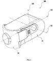
FIG. 4 is a perspective view of the dust collection device ofFIG. 1 . -
FIG. 5 is a top view of the dust collection device ofFIG. 4 . -
FIG. 6 is a perspective view of the dust collection device ofFIG. 4 when a first housing portion is separated from a second housing portion. -
FIG. 7 is a perspective view of the dust collection device ofFIG. 4 when a part of a first housing portion is cross sectioned. -
FIG. 8 is a plan view of the dust collection device ofFIG. 4 when a first housing portion is cross sectioned. -
FIG. 9 is a perspective view of the dust collection device ofFIG. 4 when a housing is cross sectioned. -
FIG. 10 is a plan view of a power tool according to a second embodiment. -
FIG. 11 is a schematic diagram of the dust collection device ofFIG. 10 when a left wall is partially cross sectioned. -
FIG. 12 is a schematic diagram of the dust collection device ofFIG. 10 when a right wall is partially cross sectioned. - A
power tool 1 according to the first embodiment as illustrated inFIG. 1 to FIG. 3 includes a toolmain body 100 and adust collection device 200. The toolmain body 100 may be a grinding-type tool which may generate a large amount of dust, thus thedust collection device 200 for collecting the dust is necessary to be arranged on this kind of tools. The toolmain body 100 may include atool housing 11, amotor 12, and afan 13. Thetool housing 11 may be provided with anoutlet 111 through which the dust is discharged out of the toolmain body 100. Thedust collection device 200 is connected to theoutlet 111. Themotor 12 and thefan 13 are arranged inside thetool housing 11. When themotor 12 operates, thefan 13 can generate an airflow and the dust can be discharged to thedust collection device 200 along with the airflow; or thedust collection device 200 may be connected to an external vacuum cleaner, and the dust is extracted into thedust collection device 200 through the vacuum cleaner; or the dust collection device may be self-contained with a dust extraction fan, and the dust is extracted into thedust collection device 200 through the dust extraction fan. - As illustrated in
FIG. 3 , the toolmain body 100 and thedust collection device 200 are detachably connected, so that the user can selectively determine whether thedust collection device 200 needs to be mounted to the toolmain body 100 to perform the dust extraction treatment. - As illustrated in
FIG. 3 to FIG. 9 , thedust collection device 200 includes ahousing 20 provided with anaccommodating chamber 201 for collecting dust. Thehousing 20 includes afirst housing portion 21 and asecond housing portion 22. Thefirst housing portion 21 and thesecond housing portion 22 are detachably connected. When thesecond housing portion 22 is joined to thefirst housing portion 21, theaccommodating chamber 201 is formed between thefirst housing portion 21 and thesecond housing portion 22. When thesecond housing portion 22 is detached from thefirst housing portion 21, theaccommodating chamber 201 is opened to form adust pouring opening 212 through which the dust is poured out of theaccommodating chamber 201. In this way, when cleaning the dust in theaccommodating chamber 201, the user only needs to detach thesecond housing portion 21 from thefirst housing portion 21; namely, the dust can be poured out through the openeddust pouring opening 212, so that the dust in theaccommodating chamber 201 can be cleaned more thoroughly. Thedust pouring opening 212 may be defined to be relatively large, which is favorable for pouring out the dust. In addition, by defining adust pouring opening 212 be means the detachable connection between thefirst housing portion 21 and thesecond housing portion 22, thehousing 20 of the dust collection device does not need to be separately provided with an opening for pouring the dust and a door for closing the opening, so that thedust collection device 200 is simple in structure and can be easy to manufacture. It should be noted that the detachable connection in the present disclosure means that thefirst housing portion 21 and thesecond housing portion 22 can be quickly detached and mounted by the user without needing an auxiliary tool. - The
first housing portion 21 has a length extending along a firststraight line 101, a width extending along a secondstraight line 102, and a height extending along a thirdstraight line 103. It should be understood that a dimension of thefirst housing portion 21 in the length should be larger than a dimension of thefirst housing portion 21 in the width, and also larger than a dimension of thefirst housing portion 21 in the height. - To facilitate description of the technical solution according to the present disclosure, terms "front", "rear", "left", "right", "up", and "down" are also defined as illustrated in
FIG. 2 . - The
first housing portion 21 in the length extending along the firststraight line 101 includes arear wall 211 facing away from the toolmain body 100. A front end of thefirst housing portion 21 opposite to therear wall 211 is opened forwards to form thedust pouring opening 212, thereby coupling thesecond housing portion 22. Thefirst housing portion 21 in the width extending along the secondstraight line 102 includes aleft wall 213 and aright wall 214. Thefirst housing portion 21 in the height extending along the thirdstraight line 103 includes anupper wall 215 and alower wall 216. The openedaccommodating chamber 201 with thedust pouring opening 212 is formed between therear wall 211, theleft wall 213, theright wall 214, theupper wall 215, and thelower wall 216. Thesecond housing portion 22 includes afront wall 225 at least partially covering thedust pouring opening 212. Thedust pouring opening 212 is opened towards the direction in which thesecond housing portion 22 is detached from thefirst housing portion 21. - The
second housing portion 22 may be inserted into thefirst housing portion 21 or be pulled out of thefirst housing portion 21 through thedust pouring opening 212 of thefirst housing portion 21 opened forward along the firststraight line 101, namely, thesecond housing portion 22 and thefirst housing portion 21 are detachably connected along the firststraight line 101. In this way, when the dust in theaccommodating chamber 201 needs to be poured out, the user may pull out thesecond housing portion 22 from thefirst housing portion 21 along the firststraight line 101, and then pour out the dust through thedust pouring opening 212 of thefirst housing portion 21 opened forward. An area of a projection of thedust pouring opening 212 onto a plane perpendicular to the firststraight line 101 is greater than an area of a projection of the outlet onto the plane perpendicular to the firststraight line 101, so that thedust pouring opening 212 is relatively large, which is favorable for pouring out the dust. - In one embodiment, the
dust collection device 200 further includes anair inlet pipe 221, acyclone pipe 222, anair duct pipe 223, and aventilation pipe 224. Theair inlet pipe 221 is configured to guide the airflow to enter thedust collection device 200 along the firststraight line 101. Thecyclone pipe 222 is configured to generate a cyclone to separate the dust from the airflow. Theair duct pipe 223 is configured to connect theair inlet pipe 221 to thecyclone pipe 222. Theventilation pipe 224 is configured to communicate an inside and an outside of thecyclone pipe 222 to guide the airflow after being subjected to dust separation by thecyclone pipe 222 out of thecyclone pipe 222. When thesecond housing portion 22 and thefirst housing portion 21 are coupled to form theaccommodating chamber 201, thecyclone pipe 222 and theair duct pipe 223 are arranged inside theaccommodating chamber 201, theair inlet pipe 221 is at least partially arranged inside theaccommodating chamber 201, and theventilation pipe 224 is also at least partially arranged inside theaccommodating chamber 201. Theair inlet pipe 221, thecyclone pipe 222, theair duct pipe 223, and theventilation pipe 224 are further fixedly connected to thesecond housing portion 22 to form an non-detachable integrate. In this way, when thesecond housing portion 22 is detached from thefirst housing portion 21 by the user to pour out the dust, theair inlet pipe 221, thecyclone pipe 222, theair duct pipe 223 and theventilation pipe 224 along with thesecond housing portion 22 are separated from thefirst housing portion 21, thereby theair inlet pipe 221, thecyclone pipe 222, theair duct pipe 223, and theventilation pipe 224 are separated from theaccommodating chamber 201, so that no other component stopping the dust in the space surrounded and formed by thefirst housing portion 21 is provided, and the dust can be more freely poured out through thedust pouring opening 212. - In one embodiment, the
air inlet pipe 221 is further configured to connect thedust collection device 200 to theoutlet 111 of the toolmain body 100. Theair inlet pipe 221 substantially extends along the firststraight line 101 and penetrates through thesecond housing portion 22 in the firststraight line 101, so that an inside and an outside of thehousing 20 are communicated by theair inlet pipe 221. Namely, the firststraight line 101 along which theair inlet pipe 221 extends coincides with the length of thehousing 20. A projection of theair inlet pipe 221 onto the plane perpendicular to the firststraight line 101 is located within a projection of thedust pouring opening 212 onto the plane perpendicular to the firststraight line 101. - In the present embodiment, the
dust collection device 200 only includes onecyclone pipe 222. Thecyclone pipe 222 substantially extends along the secondstraight line 102. The secondstraight line 102 along which thecyclone pipe 222 extends intersects the firststraight line 101 direction along which the airflow enters theair inlet pipe 221 to form an angle, and the angle is greater than or equal to 25° and less than or equal to 90° (the term "intersect" includes the case in which the secondstraight line 102 intersects the firststraight line 101 in a same plane, and further includes the case in which the secondstraight line 102 intersects other straight lines parallel to the first straight line 101). In this way, the airflow entering from theair inlet pipe 221 can enter thecyclone pipe 222 without changing the flow direction by a large angle, so that the loss of the airflow is reduced and the effect of dust extraction is improved. - In the present embodiment, the second
straight line 102 along which thecyclone pipe 222 extends is perpendicular to the firststraight line 101 along which the airflow enters theair inlet pipe 221. In one embodiment, the secondstraight line 102 direction which thecyclone pipe 222 extends coincides with the width of thehousing 20. It should be understood that, in other embodiments, a direction along which thecyclone pipe 222 extends may be different from the width of thehousing 20. Thecyclone pipe 222 is provided with afirst end 222a for air intake and asecond end 222b for dust discharge in the secondstraight line 102. In another embodiment, thefirst end 222a is more adjacent to theleft wall 213, and thesecond end 222b is more adjacent to theright wall 214. Theair duct pipe 223 is configured to form anair duct 223a for communicating theair inlet pipe 221 with thecyclone pipe 222. Theventilation pipe 224 is arranged at thefirst end 222a of thecyclone pipe 222 and communicated with thecyclone pipe 222. In order to enable the airflow to flow out of thedust collection device 200, thefirst housing portion 21 is further formed with anair outlet 213a. Theair outlet 213a is corresponding to a position of theventilation pipe 224 and is communicated with theventilation pipe 224. It should be understood that, in other embodiments, theventilation pipe 224 may also directly protrude out of thehousing 20. Theventilation pipe 224 and thefirst end 222a are more adjacent to theleft wall 213 in the secondstraight line 102, and theair outlet 213a also needs to be more adjacent to thefirst end 222a. Therefore, theair outlet 213a is arranged on theleft wall 213 more adjacent to thefirst end 222a, and penetrates through theleft wall 213 in the secondstraight line 102. Thefront wall 225 is configured to close thedust pouring opening 212 of thefirst housing portion 21 opened forward on condition that thesecond housing portion 22 is coupled to thefirst housing portion 21. Theair inlet pipe 221 is arranged on thefront wall 225. Correspondingly, therear wall 211 is farther from theair inlet pipe 221 than thefront wall 225, so that thedust collection device 200 is reasonable in structure, convenient in disassembly and assembly, suitable in size and good in dust collecting effect. - When the
power tool 1 performs the grinding operation, the airflow with the dust firstly enters thedust collection device 200 through theair inlet pipe 221, and then enters thecyclone pipe 222 through theair duct pipe 223. At this moment, the dust is guided to theaccommodating chamber 201 through thesecond end 222b under the action of thecyclone pipe 222, so that the airflow without the dust flows out from theventilation pipe 224 and theair outlet 213a in sequence at the same time. - The
cyclone pipe 222 further includes anintermediate section 222c arranged between thefirst end 222a and thesecond end 222c. Theintermediate section 222c is a hollow cylinder shape. Theintermediate section 222c is provided with aninner wall 222d of which a cross section in a plane perpendicular to the secondstraight line 102 is a circular shape. A ratio of a diameter of the circularinner wall 222d of theintermediate section 222c to a length L of thecyclone pipe 222 along the secondstraight line 102 is greater than or equal to 0.4, and less than or equal to 0.7. In this way, when the length of thecyclone pipe 222 is constant, an area of the cross section of theinner wall 222d of thecyclone pipe 222 will not be too small to result in that theinner wall 222d of thecyclone pipe 222 generates a relatively large resistance to the airflow, thereby avoiding the problem that the efficiency of the dust extraction is reduced due to the decrease of flow rate of the airflow. In addition, when the length of thecyclone pipe 222 is constant, the area of the cross section of theinner wall 222d of thecyclone pipe 222 will not be too large to result in that the centrifugal force of the dust is insufficient, thereby avoiding the problem that the dust separation is not thorough due to the low centrifugal force. In another embodiment, the diameter of the circularinner wall 222d of theintermediate section 222c of thecyclone pipe 222 is greater than or equal to 30mm, and less than or equal to 60mm. - In another embodiment, along a direction parallel to the second
straight line 102, theair inlet pipe 221 is located between thefirst end 222a and thesecond end 222b. In another embodiment, in the secondstraight line 102, theair inlet pipe 221 is substantially arranged at a center offront wall 225; namely, in the secondstraight line 102, theair inlet pipe 221 is substantially arranged at a center of thefirst housing portion 21; and in the thirdstraight line 103, theair inlet pipe 221 is substantially arranged at the center of thefront wall 225. It should be noted that it is known that, in general, thedust collection device 200 is not necessarily a completely symmetrical structure. Therefore, the center refers to a portion which is substantially located at the center, and is not limited to a center in a strict sense. Theair inlet pipe 221 is a cylindrical pipe having a central axis in the firststraight line 101. The diameter of the circularinner wall 222d of theintermediate section 222c is larger than a diameter of an inner wall of theair inlet pipe 221. - The
air duct pipe 223 includes athird end 223b for connecting theair inlet pipe 221 and afourth end 223c for connecting thecyclone pipe 222, where thethird end 223b and thefourth end 223c are located at two ends of theair duct pipe 223 in a direction along which theair duct pipe 223 extends. Theair duct pipe 223 further includes anoblique portion 223d which at least partially extends along a fourthstraight line 104 obliquely intersecting the secondstraight line 102. The fourthstraight line 104 along which theoblique portion 223b extends obliquely intersects the firststraight line 101. In this way, in the secondstraight line 102, a height difference H is present between thefourth end 223c and thethird end 223b, such that thefirst end 222a of thecyclone pipe 222 is arranged to be as adjacent as possible to theleft wall 213, thus the size of thedust collection device 200 in the width may be reduced as much as possible on condition that a size of thecyclone pipe 222 is constant, which facilitates the miniaturization of thedust collection device 200. It should be noted that the height difference refers to the height difference between thefourth end 223c and thethird end 223b along the secondstraight line 102, and is not limited to the difference in the height direction. - As illustrated in
FIG. 9 , thedust collection device 200 further includes anair guiding portion 217. Theair guiding portion 217 is an air guiding surface extending perpendicular to the firststraight line 101. The air guiding surface is connected to theair duct pipe 223 and thecyclone pipe 222. The air guiding surface may at least partially be arranged at theinner wall 222d of thecyclone pipe 222. In this way, theair guiding portion 217 is operative to guide the airflow from theair duct 223a to enter thecyclone pipe 222 substantially along the direction perpendicular to the secondstraight line 102, so that the obstruction of the airflow by thecyclone pipe 222 is reduced, thus the loss of the airflow is reduced and the effect of dust separation is improved. - As illustrated in
FIG. 5 and FIG. 6 , anelastic tab 218 is formed at an outer side of thefirst housing portion 21, and provided with ahook portion 218a. Thesecond housing portion 22 is provided with acoupling portion 226 for cooperating with theelastic tab 218. Thecoupling portion 226 is provided with aslot 226a for embedding at least part of thehook portion 218a. In this way, when thesecond housing portion 22 is coupled to thefirst housing portion 21, theelastic tab 218 may generate an elastic force that is operative to move thehook portion 218a toward theslot 226a and to be embedded into theslot 226a. The elastic force generated by theelastic tab 218 may be generated by the structure of theelastic tab 218, and may be generated by the manner that aspring 219 for biasing theelastic tab 218 is arranged on thefirst housing portion 21. - When the
dust collection device 200 is mounted to the toolmain body 100, thedust collection device 200 includes adust heaping plane 216a for heaping the dust. In one embodiment, thedust heaping plane 216a may be formed by thelower wall 216 of thefirst housing portion 21. As illustrated inFIG. 1 andFIG. 8 , when thedust collection device 200 is mounted to the toolmain body 100 and thepower tool 1 is arranged on an working plane parallel to a horizontal plane, thedust heaping plane 216a obliquely intersects the horizontal plane, so that the dust out of thecyclone pipe 222 is heaped as downward and forward as possible, thus the utilization rate of theaccommodating chamber 201 is improved. - In the present embodiment, the tool
main body 100 may specifically be a sander. It is known that the sander will generate a relatively large amount of dust during sanding and polishing process, thus it is necessary to connect thedust collection device 200 of the present embodiment to the sander. It should be understood that the toolmain body 100 may be other tools requiring dust removal. - The power tool 3 of a second embodiment as illustrated in
FIG. 10 has the same toolmain body 300 as thepower tool 1 of the first embodiment. Thedust collection device 400 of the present embodiment further includes a guiding structure for guiding the second housing portion 42 to be joined to thefirst housing portion 41 along the firststraight line 301. - In one embodiment, as illustrated in
FIG. 11 andFIG. 12 , theleft wall 413 of thefirst housing portion 41 is further provided with afirst guiding rail 413b for guiding the second housing portion 42 to be joined to thefirst housing portion 41 along the firststraight line 301. Theright wall 414 is provided with asecond guiding rail 414a. The second housing portion 42 or thecyclone pipe 222 fixedly connected to the second housing portion 42 is correspondingly provided with afirst matching portion 426 cooperating with the first guidingrail 413b and thesecond matching portion 427 cooperating with thesecond guiding rail 414a. In another embodiment, the first guidingrail 413b is provided with afirst guiding groove 413c, and thesecond guiding rail 414a is provided with asecond guiding groove 414b, so that a part of thefirst matching portion 426 may be embedded into thefirst guiding groove 413c, and a part of thesecond matching portion 427 may be embedded into thesecond guiding groove 414b, thus the second housing portion 42 is guided to be joined to thefirst housing portion 41 along the firststraight line 301. - In another embodiment, one end of the
first guiding groove 413c facing toward theair inlet pipe 421 is a flaredshape 413d, and one end of thesecond guiding groove 414b facing toward theair inlet pipe 421 is a flaredshape 414c, so that a trouble of requiring a tight alignment when the second housing portion 42 is inserted into thefirst housing portion 41 is avoided, thus the second housing portion 42 can be quickly inserted into thefirst housing portion 41 by the user. - The foregoing has illustrated and described the basic principles, main features, and advantages of the present disclosure. It is to be understood by those having skill in the art that the foregoing embodiments are not intended to limit the present disclosure in any form. All technical solutions obtained by means of equivalent substitution or equivalent transformation shall all fall in the scope of protection of the present disclosure.
Claims (25)
- A dust collection device, comprising:a housing, defining an accommodating chamber for collecting a dust;an air inlet pipe, configured to guide an airflow to enter the dust collection device along a first straight line;a cyclone pipe, extending along a second straight line, and comprising a first end for air intake and a second end for dust discharge along the second straight line;an air duct pipe, defining an air duct communicating the air inlet pipe with the cyclone pipe; anda ventilation pipe, arranged at the first end of the cyclone pipe and communicated with the cyclone pipe, the ventilation pipe being configured to guide the airflow after being subjected to dust separation performed by the cyclone pipe out of the housing;wherein the housing defines an air outlet communicated with the ventilation pipe or through which the ventilation pipe extends out of the housing; the second straight line along which the cyclone pipe extends intersect the first straight line to form an angle greater than or equal to 25° and less than or equal to 90°.
- The dust collection device according to claim 1, wherein the second straight line along which the cyclone pipe extends and the first straight line are perpendicular to each other.
- The dust collection device according to claim 1, further comprising:
an air guiding portion, configured to guide the airflow from the air duct to enter the cyclone pipe substantially along a direction perpendicular to the second straight line. - The dust collection device according to claim 1, wherein the housing comprises:a first housing portion, defining the air outlet; anda second housing portion, detachably connected to the first housing portion;wherein the accommodating chamber is formed when the second housing portion is joined with the first housing portion.
- The dust collection device according to claim 4, wherein the air inlet pipe, the cyclone pipe, the air duct pipe, and the ventilation pipe are fixedly connected to the second housing portion.
- The dust collection device according to claim 1, wherein the air duct pipe at least partially extends along a direction obliquely intersecting the second straight line.
- The dust collection device according to claim 6, wherein the air duct pipe comprises a third end connected to the air inlet pipe and a fourth end connected to the cyclone pipe, the third end and the fourth end being located at two ends along an extending direction of the air duct pipe; and
wherein along the second straight line, the fourth end and the third end of the air duct pipe constitute a height difference. - The dust collection device according to claim 1, wherein the housing defines a length direction extending along the first straight line; the second straight line along which the cyclone pipe extends in the accommodating chamber is perpendicular to the length direction of the housing.
- The dust collection device according to claim 1, wherein the cyclone pipe further comprises an intermediate section arranged between the first end and the second end along the second straight line, the intermediate section has an inner wall which has a circular cross section in a plane perpendicular to the second straight line; a ratio of a diameter of the circular shape formed by the cross section of the inner wall of the intermediate section in the plane perpendicular to the second straight line to a length of cyclone pipe along the second straight line is greater than or equal to 0.4 and less than or equal to 0.7.
- The dust collection device according to claim 9, wherein the diameter of the inner wall of the intermediate section is greater than or equal to 30mm and less than or equal to 60mm.
- The dust collection device according to claim 9, wherein the air inlet pipe is a cylinder-shaped pipe; the diameter of the inner wall of the intermediate section is greater than a diameter of an inner wall of the air inlet pipe.
- The dust collection device according to claim 9, wherein a number of the cyclone pipe is 1.
- The dust collection device according to claim 9, wherein the first straight line along which the airflow enters the air inlet pipe and the second straight line along which the cyclone pipe extends are further perpendicular to each other.
- The dust collection device according to claim 9, wherein the air inlet pipe is located between the first end and the second end along a direction parallel to the second straight line.
- The dust collection device according to claim 1, wherein the housing further comprises:a first housing portion, defining an air outlet communicated with the ventilation pipe or through which the ventilation pipe extends out of the housing; anda second housing portion, detachably connected to the first housing portion;wherein the accommodating chamber is formed by the second housing portion and the first housing portion when the second housing portion is joined with the first housing portion; the accommodating chamber is opened to form a dust pouring opening for pouring out the dust in the accommodating chamber in response to detaching the second housing portion and the first housing portion from each other.
- The dust collection device according to claim 15, wherein the air inlet pipe, the cyclone pipe, the air duct pipe, and the ventilation pipe are fixedly connected to the second housing portion, so that the air inlet pipe, the cyclone pipe, the air duct pipe, and the ventilation pipe are separated from the accommodating chamber in response to the second housing portion being detached from the first housing portion.
- The dust collection device according to claim 15, wherein the dust pouring opening is opened toward a direction in which the second housing portion is detached from the first housing portion.
- The dust collection device according to claim 15, wherein the first housing portion is provided with a guiding rail for guiding the second housing portion to be joined to the first housing portion along the first straight line;
the second housing portion is provided with a matching portion for cooperating with the guiding rail. - The dust collection device according to claim 15, wherein the housing has a length extending along the first straight line, the housing comprises a front wall and a rear wall at two ends in the length of the housing;
wherein the rear wall is formed by the first housing portion, and the front wall is formed by the second housing portion. - The dust collection device according to claim 15, wherein an outer side of the first housing portion is further provided with an elastic tab having a hook portion, the second housing portion is provided with a slot into which the hook portion is partially embedded;
the elastic tab is configured to generate an elastic force that is operative to move the hook portion toward the slot to be embedded into the slot. - The dust collection device according to claim 15, wherein the air inlet pipe is configured to communicate an inside and an outside of the housing, the air inlet pipe is fixedly connected to the second housing portion and penetrates through the second housing portion in the first straight line.
- The dust collection device according to claim 15, wherein the second straight line along which the cyclone pipe extends and the first straight line are perpendicular to each other;
the housing has a length extending along the first straight line and a width extending along the second straight line; a size of the housing in the length is greater than a size of the housing in the width. - The dust collection device according to claim 15, wherein a projection of the air inlet pipe onto a plane perpendicular to the first straight line is located within a projection of the dust pouring opening onto the plane.
- A power tool, comprising a tool housing, a motor arranged inside the tool housing, and the dust collecting device according to any one of claims 1 to 23.
- The power tool according to claim 24, wherein the housing comprises a dust heaping plane for heaping the dust; wherein on condition that the dust collection device is mounted onto the tool housing and the power tool is arranged on a working plane parallel to a horizontal plane, the dust heaping plane obliquely intersects the horizontal plane .
Applications Claiming Priority (5)
| Application Number | Priority Date | Filing Date | Title |
|---|---|---|---|
| CN201710217774 | 2017-04-01 | ||
| CN201710984266.8A CN108655958B (en) | 2017-04-01 | 2017-10-20 | Dust collection devices and power tools |
| CN201721371202.2U CN207509161U (en) | 2017-04-01 | 2017-10-20 | Dust collect plant and electric tool |
| CN201710983764.0A CN108656033B (en) | 2017-04-01 | 2017-10-20 | Dust collection devices and power tools |
| PCT/CN2018/081040 WO2018177355A1 (en) | 2017-04-01 | 2018-03-29 | Dust collecting device and electric tool |
Publications (3)
| Publication Number | Publication Date |
|---|---|
| EP3569365A1 true EP3569365A1 (en) | 2019-11-20 |
| EP3569365A4 EP3569365A4 (en) | 2020-07-29 |
| EP3569365B1 EP3569365B1 (en) | 2024-06-19 |
Family
ID=62355257
Family Applications (1)
| Application Number | Title | Priority Date | Filing Date |
|---|---|---|---|
| EP18777842.8A Active EP3569365B1 (en) | 2017-04-01 | 2018-03-29 | Dust collecting device and electric tool |
Country Status (3)
| Country | Link |
|---|---|
| US (1) | US12151338B2 (en) |
| EP (1) | EP3569365B1 (en) |
| CN (6) | CN108655958B (en) |
Families Citing this family (8)
| Publication number | Priority date | Publication date | Assignee | Title |
|---|---|---|---|---|
| CN108655958B (en) * | 2017-04-01 | 2024-04-26 | 南京泉峰科技有限公司 | Dust collection devices and power tools |
| DE102018251715A1 (en) * | 2018-12-27 | 2020-07-02 | Robert Bosch Gmbh | Hand tool |
| CN113927427B (en) * | 2020-06-29 | 2023-05-26 | 南京泉峰科技有限公司 | Cyclone dust collecting device and polishing device |
| EP3932277B1 (en) * | 2020-06-29 | 2022-09-14 | Nanjing Chervon Industry Co., Ltd. | Cyclone dust collecting device and grinding device |
| CN114714214B (en) * | 2021-01-05 | 2026-02-06 | 南京泉峰科技有限公司 | Dust collecting device and polishing tool provided with same |
| CN112643492B (en) * | 2021-01-23 | 2021-12-03 | 浙江奥特工具有限公司 | Handheld angle grinder |
| DE102022113267A1 (en) * | 2021-06-03 | 2022-12-08 | Makita Corporation | Impact tool and dust removal system |
| JP7664097B2 (en) * | 2021-06-17 | 2025-04-17 | 株式会社マキタ | Metalworking dust collection attachments and grinding tools |
Family Cites Families (22)
| Publication number | Priority date | Publication date | Assignee | Title |
|---|---|---|---|---|
| DE19827173A1 (en) * | 1998-06-18 | 1999-12-23 | Bosch Gmbh Robert | Dust suction system for hand power tool |
| US6833016B2 (en) * | 2003-03-27 | 2004-12-21 | Oneida Air Systems, Inc | Dust collection system |
| DE602005010468D1 (en) * | 2004-07-16 | 2008-11-27 | Makita Corp | Saw with dust collector |
| DE602004011624T2 (en) * | 2004-11-19 | 2009-01-29 | Black & Decker Inc., Newark | Dust extraction for powered tools |
| GB0500469D0 (en) * | 2005-01-11 | 2005-02-16 | Positec Group Ltd | Tool |
| DE102005020400A1 (en) * | 2005-05-02 | 2006-11-09 | Positec Group Limited, Wanchai | Device for filtering extremely fine dust |
| KR100647195B1 (en) * | 2005-06-03 | 2006-11-23 | 삼성광주전자 주식회사 | Cyclone dust collector |
| JP2007061977A (en) | 2005-09-01 | 2007-03-15 | Makita Corp | Dust collector for power tool |
| JP4652202B2 (en) * | 2005-10-03 | 2011-03-16 | 株式会社マキタ | Dust collection container for electric tools |
| CN101096095B (en) * | 2006-06-26 | 2011-12-07 | 苏州宝时得电动工具有限公司 | Hand-held electric instrument |
| CN200981026Y (en) * | 2006-08-11 | 2007-11-28 | 苏州宝时得电动工具有限公司 | Electric tool cyclone dust-removing device |
| CN201823613U (en) * | 2010-07-12 | 2011-05-11 | 浙江瑞普环境技术有限公司 | Cyclone separator |
| CN101913110A (en) | 2010-08-04 | 2010-12-15 | 袁寿勤 | Dust-removing angle grinder |
| CN201824205U (en) * | 2010-09-21 | 2011-05-11 | 台州美能环保设备有限公司 | Dust removing grinder |
| US8800682B2 (en) * | 2010-10-01 | 2014-08-12 | Black & Decker Inc. | Dust extraction for power tools |
| US20160193714A1 (en) * | 2013-09-02 | 2016-07-07 | 3M Innovative Properties Company | Portable system for collecting a dust from a dust producing machine |
| CN104511888A (en) * | 2013-09-30 | 2015-04-15 | 南京德朔实业有限公司 | Dust collection attachment |
| CN204166218U (en) * | 2014-09-25 | 2015-02-18 | 陈婷婷 | A kind of eye glass frame and temple syndeton |
| CN204843868U (en) * | 2015-07-31 | 2015-12-09 | 南京德朔实业有限公司 | Dust collecting device and combination with electric tool thereof |
| CN106466833A (en) * | 2015-08-14 | 2017-03-01 | 南京德朔实业有限公司 | Accessories apparatus and its with the combining of power tool |
| CN105642947B (en) * | 2016-04-01 | 2018-07-10 | 重庆大学 | A kind of electric drill dust-extraction unit |
| CN108655958B (en) * | 2017-04-01 | 2024-04-26 | 南京泉峰科技有限公司 | Dust collection devices and power tools |
-
2017
- 2017-10-20 CN CN201710984266.8A patent/CN108655958B/en active Active
- 2017-10-20 CN CN201721361839.3U patent/CN207344515U/en not_active Expired - Fee Related
- 2017-10-20 CN CN201721371202.2U patent/CN207509161U/en not_active Expired - Fee Related
- 2017-10-20 CN CN201710983764.0A patent/CN108656033B/en active Active
- 2017-10-20 CN CN201721374343.XU patent/CN207509162U/en not_active Expired - Fee Related
- 2017-10-20 CN CN201721361546.5U patent/CN207509034U/en not_active Expired - Fee Related
-
2018
- 2018-03-29 EP EP18777842.8A patent/EP3569365B1/en active Active
-
2019
- 2019-07-31 US US16/527,818 patent/US12151338B2/en active Active
Also Published As
| Publication number | Publication date |
|---|---|
| CN108656033A (en) | 2018-10-16 |
| CN108655958A (en) | 2018-10-16 |
| US20190351528A1 (en) | 2019-11-21 |
| CN207509161U (en) | 2018-06-19 |
| CN207509162U (en) | 2018-06-19 |
| US12151338B2 (en) | 2024-11-26 |
| CN108655958B (en) | 2024-04-26 |
| CN207344515U (en) | 2018-05-11 |
| CN108656033B (en) | 2024-04-30 |
| CN207509034U (en) | 2018-06-19 |
| EP3569365A4 (en) | 2020-07-29 |
| EP3569365B1 (en) | 2024-06-19 |
Similar Documents
| Publication | Publication Date | Title |
|---|---|---|
| EP3569365B1 (en) | Dust collecting device and electric tool | |
| EP3641612B1 (en) | A surface cleaning apparatus | |
| WO2017117868A1 (en) | Handheld dust collector | |
| GB2463089A (en) | Directing air into a grille | |
| CN103536248A (en) | Dust collector | |
| CN108903790A (en) | Dust catcher | |
| CN204843868U (en) | Dust collecting device and combination with electric tool thereof | |
| CN209899259U (en) | Hand-held silent dust collector | |
| JP5313067B2 (en) | Electric vacuum cleaner | |
| WO2018177355A1 (en) | Dust collecting device and electric tool | |
| CN216703761U (en) | Novel printing machine dust removal that induced drafts device | |
| JP5776822B2 (en) | Electric vacuum cleaner | |
| CN108903805A (en) | Motor base for HEPA self-cleaning type dust collector | |
| CN115500730A (en) | Dust-air separation device and dust collector | |
| CN220555768U (en) | Scald and dust collection assembly | |
| CN212533232U (en) | Magnetic attraction type heavy object separator | |
| CN218044938U (en) | A double-chamber dust cup and mite remover | |
| CN205950463U (en) | Multi -functional electric mill dust extraction | |
| CN219537702U (en) | Dandruff removing device | |
| CN205107567U (en) | multifunctional steam cleaner | |
| CN221997712U (en) | Handheld wet-type cleaning appliance and wet-type dust removal device thereof | |
| CN222308517U (en) | Novel wet dust collector | |
| CN215147871U (en) | Abrasive belt machine | |
| CA2450060A1 (en) | Cyclone vacuum cleaner | |
| CN219048235U (en) | Floor brush structure and cleaning equipment |
Legal Events
| Date | Code | Title | Description |
|---|---|---|---|
| STAA | Information on the status of an ep patent application or granted ep patent |
Free format text: STATUS: THE INTERNATIONAL PUBLICATION HAS BEEN MADE |
|
| PUAI | Public reference made under article 153(3) epc to a published international application that has entered the european phase |
Free format text: ORIGINAL CODE: 0009012 |
|
| STAA | Information on the status of an ep patent application or granted ep patent |
Free format text: STATUS: REQUEST FOR EXAMINATION WAS MADE |
|
| 17P | Request for examination filed |
Effective date: 20190813 |
|
| AK | Designated contracting states |
Kind code of ref document: A1 Designated state(s): AL AT BE BG CH CY CZ DE DK EE ES FI FR GB GR HR HU IE IS IT LI LT LU LV MC MK MT NL NO PL PT RO RS SE SI SK SM TR |
|
| AX | Request for extension of the european patent |
Extension state: BA ME |
|
| RIC1 | Information provided on ipc code assigned before grant |
Ipc: B25D 17/14 20060101ALI20200317BHEP Ipc: B24B 55/10 20060101ALI20200317BHEP Ipc: B23Q 11/00 20060101ALI20200317BHEP Ipc: B25F 5/00 20060101AFI20200317BHEP |
|
| DAV | Request for validation of the european patent (deleted) | ||
| DAX | Request for extension of the european patent (deleted) | ||
| A4 | Supplementary search report drawn up and despatched |
Effective date: 20200629 |
|
| RIC1 | Information provided on ipc code assigned before grant |
Ipc: B24B 55/10 20060101ALI20200623BHEP Ipc: B25F 5/00 20060101AFI20200623BHEP Ipc: B23Q 11/00 20060101ALI20200623BHEP Ipc: B25D 17/14 20060101ALI20200623BHEP |
|
| STAA | Information on the status of an ep patent application or granted ep patent |
Free format text: STATUS: EXAMINATION IS IN PROGRESS |
|
| 17Q | First examination report despatched |
Effective date: 20221212 |
|
| GRAP | Despatch of communication of intention to grant a patent |
Free format text: ORIGINAL CODE: EPIDOSNIGR1 |
|
| STAA | Information on the status of an ep patent application or granted ep patent |
Free format text: STATUS: GRANT OF PATENT IS INTENDED |
|
| GRAS | Grant fee paid |
Free format text: ORIGINAL CODE: EPIDOSNIGR3 |
|
| INTG | Intention to grant announced |
Effective date: 20240212 |
|
| GRAA | (expected) grant |
Free format text: ORIGINAL CODE: 0009210 |
|
| STAA | Information on the status of an ep patent application or granted ep patent |
Free format text: STATUS: THE PATENT HAS BEEN GRANTED |
|
| AK | Designated contracting states |
Kind code of ref document: B1 Designated state(s): AL AT BE BG CH CY CZ DE DK EE ES FI FR GB GR HR HU IE IS IT LI LT LU LV MC MK MT NL NO PL PT RO RS SE SI SK SM TR |
|
| REG | Reference to a national code |
Ref country code: GB Ref legal event code: FG4D |
|
| REG | Reference to a national code |
Ref country code: CH Ref legal event code: EP |
|
| REG | Reference to a national code |
Ref country code: DE Ref legal event code: R096 Ref document number: 602018070797 Country of ref document: DE |
|
| PG25 | Lapsed in a contracting state [announced via postgrant information from national office to epo] |
Ref country code: BG Free format text: LAPSE BECAUSE OF FAILURE TO SUBMIT A TRANSLATION OF THE DESCRIPTION OR TO PAY THE FEE WITHIN THE PRESCRIBED TIME-LIMIT Effective date: 20240619 |
|
| PG25 | Lapsed in a contracting state [announced via postgrant information from national office to epo] |
Ref country code: FI Free format text: LAPSE BECAUSE OF FAILURE TO SUBMIT A TRANSLATION OF THE DESCRIPTION OR TO PAY THE FEE WITHIN THE PRESCRIBED TIME-LIMIT Effective date: 20240619 Ref country code: HR Free format text: LAPSE BECAUSE OF FAILURE TO SUBMIT A TRANSLATION OF THE DESCRIPTION OR TO PAY THE FEE WITHIN THE PRESCRIBED TIME-LIMIT Effective date: 20240619 |
|
| REG | Reference to a national code |
Ref country code: LT Ref legal event code: MG9D |
|
| PG25 | Lapsed in a contracting state [announced via postgrant information from national office to epo] |
Ref country code: GR Free format text: LAPSE BECAUSE OF FAILURE TO SUBMIT A TRANSLATION OF THE DESCRIPTION OR TO PAY THE FEE WITHIN THE PRESCRIBED TIME-LIMIT Effective date: 20240920 |
|
| REG | Reference to a national code |
Ref country code: NL Ref legal event code: MP Effective date: 20240619 |
|
| PG25 | Lapsed in a contracting state [announced via postgrant information from national office to epo] |
Ref country code: LV Free format text: LAPSE BECAUSE OF FAILURE TO SUBMIT A TRANSLATION OF THE DESCRIPTION OR TO PAY THE FEE WITHIN THE PRESCRIBED TIME-LIMIT Effective date: 20240619 |
|
| PG25 | Lapsed in a contracting state [announced via postgrant information from national office to epo] |
Ref country code: BG Free format text: LAPSE BECAUSE OF FAILURE TO SUBMIT A TRANSLATION OF THE DESCRIPTION OR TO PAY THE FEE WITHIN THE PRESCRIBED TIME-LIMIT Effective date: 20240619 Ref country code: NO Free format text: LAPSE BECAUSE OF FAILURE TO SUBMIT A TRANSLATION OF THE DESCRIPTION OR TO PAY THE FEE WITHIN THE PRESCRIBED TIME-LIMIT Effective date: 20240919 Ref country code: LV Free format text: LAPSE BECAUSE OF FAILURE TO SUBMIT A TRANSLATION OF THE DESCRIPTION OR TO PAY THE FEE WITHIN THE PRESCRIBED TIME-LIMIT Effective date: 20240619 Ref country code: HR Free format text: LAPSE BECAUSE OF FAILURE TO SUBMIT A TRANSLATION OF THE DESCRIPTION OR TO PAY THE FEE WITHIN THE PRESCRIBED TIME-LIMIT Effective date: 20240619 Ref country code: GR Free format text: LAPSE BECAUSE OF FAILURE TO SUBMIT A TRANSLATION OF THE DESCRIPTION OR TO PAY THE FEE WITHIN THE PRESCRIBED TIME-LIMIT Effective date: 20240920 Ref country code: FI Free format text: LAPSE BECAUSE OF FAILURE TO SUBMIT A TRANSLATION OF THE DESCRIPTION OR TO PAY THE FEE WITHIN THE PRESCRIBED TIME-LIMIT Effective date: 20240619 Ref country code: RS Free format text: LAPSE BECAUSE OF FAILURE TO SUBMIT A TRANSLATION OF THE DESCRIPTION OR TO PAY THE FEE WITHIN THE PRESCRIBED TIME-LIMIT Effective date: 20240919 |
|
| PG25 | Lapsed in a contracting state [announced via postgrant information from national office to epo] |
Ref country code: NL Free format text: LAPSE BECAUSE OF FAILURE TO SUBMIT A TRANSLATION OF THE DESCRIPTION OR TO PAY THE FEE WITHIN THE PRESCRIBED TIME-LIMIT Effective date: 20240619 |
|
| REG | Reference to a national code |
Ref country code: AT Ref legal event code: MK05 Ref document number: 1695645 Country of ref document: AT Kind code of ref document: T Effective date: 20240619 |
|
| PG25 | Lapsed in a contracting state [announced via postgrant information from national office to epo] |
Ref country code: NL Free format text: LAPSE BECAUSE OF FAILURE TO SUBMIT A TRANSLATION OF THE DESCRIPTION OR TO PAY THE FEE WITHIN THE PRESCRIBED TIME-LIMIT Effective date: 20240619 |
|
| PG25 | Lapsed in a contracting state [announced via postgrant information from national office to epo] |
Ref country code: PT Free format text: LAPSE BECAUSE OF FAILURE TO SUBMIT A TRANSLATION OF THE DESCRIPTION OR TO PAY THE FEE WITHIN THE PRESCRIBED TIME-LIMIT Effective date: 20241021 |
|
| PG25 | Lapsed in a contracting state [announced via postgrant information from national office to epo] |
Ref country code: PT Free format text: LAPSE BECAUSE OF FAILURE TO SUBMIT A TRANSLATION OF THE DESCRIPTION OR TO PAY THE FEE WITHIN THE PRESCRIBED TIME-LIMIT Effective date: 20241021 |
|
| PG25 | Lapsed in a contracting state [announced via postgrant information from national office to epo] |
Ref country code: PL Free format text: LAPSE BECAUSE OF FAILURE TO SUBMIT A TRANSLATION OF THE DESCRIPTION OR TO PAY THE FEE WITHIN THE PRESCRIBED TIME-LIMIT Effective date: 20240619 |
|
| PG25 | Lapsed in a contracting state [announced via postgrant information from national office to epo] |
Ref country code: EE Free format text: LAPSE BECAUSE OF FAILURE TO SUBMIT A TRANSLATION OF THE DESCRIPTION OR TO PAY THE FEE WITHIN THE PRESCRIBED TIME-LIMIT Effective date: 20240619 |
|
| PG25 | Lapsed in a contracting state [announced via postgrant information from national office to epo] |
Ref country code: IS Free format text: LAPSE BECAUSE OF FAILURE TO SUBMIT A TRANSLATION OF THE DESCRIPTION OR TO PAY THE FEE WITHIN THE PRESCRIBED TIME-LIMIT Effective date: 20241019 Ref country code: AT Free format text: LAPSE BECAUSE OF FAILURE TO SUBMIT A TRANSLATION OF THE DESCRIPTION OR TO PAY THE FEE WITHIN THE PRESCRIBED TIME-LIMIT Effective date: 20240619 |
|
| PG25 | Lapsed in a contracting state [announced via postgrant information from national office to epo] |
Ref country code: CZ Free format text: LAPSE BECAUSE OF FAILURE TO SUBMIT A TRANSLATION OF THE DESCRIPTION OR TO PAY THE FEE WITHIN THE PRESCRIBED TIME-LIMIT Effective date: 20240619 |
|
| PG25 | Lapsed in a contracting state [announced via postgrant information from national office to epo] |
Ref country code: RO Free format text: LAPSE BECAUSE OF FAILURE TO SUBMIT A TRANSLATION OF THE DESCRIPTION OR TO PAY THE FEE WITHIN THE PRESCRIBED TIME-LIMIT Effective date: 20240619 Ref country code: SK Free format text: LAPSE BECAUSE OF FAILURE TO SUBMIT A TRANSLATION OF THE DESCRIPTION OR TO PAY THE FEE WITHIN THE PRESCRIBED TIME-LIMIT Effective date: 20240619 |
|
| PG25 | Lapsed in a contracting state [announced via postgrant information from national office to epo] |
Ref country code: ES Free format text: LAPSE BECAUSE OF FAILURE TO SUBMIT A TRANSLATION OF THE DESCRIPTION OR TO PAY THE FEE WITHIN THE PRESCRIBED TIME-LIMIT Effective date: 20240619 Ref country code: SM Free format text: LAPSE BECAUSE OF FAILURE TO SUBMIT A TRANSLATION OF THE DESCRIPTION OR TO PAY THE FEE WITHIN THE PRESCRIBED TIME-LIMIT Effective date: 20240619 |
|
| PG25 | Lapsed in a contracting state [announced via postgrant information from national office to epo] |
Ref country code: SM Free format text: LAPSE BECAUSE OF FAILURE TO SUBMIT A TRANSLATION OF THE DESCRIPTION OR TO PAY THE FEE WITHIN THE PRESCRIBED TIME-LIMIT Effective date: 20240619 Ref country code: SK Free format text: LAPSE BECAUSE OF FAILURE TO SUBMIT A TRANSLATION OF THE DESCRIPTION OR TO PAY THE FEE WITHIN THE PRESCRIBED TIME-LIMIT Effective date: 20240619 Ref country code: RO Free format text: LAPSE BECAUSE OF FAILURE TO SUBMIT A TRANSLATION OF THE DESCRIPTION OR TO PAY THE FEE WITHIN THE PRESCRIBED TIME-LIMIT Effective date: 20240619 Ref country code: PL Free format text: LAPSE BECAUSE OF FAILURE TO SUBMIT A TRANSLATION OF THE DESCRIPTION OR TO PAY THE FEE WITHIN THE PRESCRIBED TIME-LIMIT Effective date: 20240619 Ref country code: IS Free format text: LAPSE BECAUSE OF FAILURE TO SUBMIT A TRANSLATION OF THE DESCRIPTION OR TO PAY THE FEE WITHIN THE PRESCRIBED TIME-LIMIT Effective date: 20241019 Ref country code: ES Free format text: LAPSE BECAUSE OF FAILURE TO SUBMIT A TRANSLATION OF THE DESCRIPTION OR TO PAY THE FEE WITHIN THE PRESCRIBED TIME-LIMIT Effective date: 20240619 Ref country code: EE Free format text: LAPSE BECAUSE OF FAILURE TO SUBMIT A TRANSLATION OF THE DESCRIPTION OR TO PAY THE FEE WITHIN THE PRESCRIBED TIME-LIMIT Effective date: 20240619 Ref country code: CZ Free format text: LAPSE BECAUSE OF FAILURE TO SUBMIT A TRANSLATION OF THE DESCRIPTION OR TO PAY THE FEE WITHIN THE PRESCRIBED TIME-LIMIT Effective date: 20240619 Ref country code: AT Free format text: LAPSE BECAUSE OF FAILURE TO SUBMIT A TRANSLATION OF THE DESCRIPTION OR TO PAY THE FEE WITHIN THE PRESCRIBED TIME-LIMIT Effective date: 20240619 |
|
| PG25 | Lapsed in a contracting state [announced via postgrant information from national office to epo] |
Ref country code: IT Free format text: LAPSE BECAUSE OF FAILURE TO SUBMIT A TRANSLATION OF THE DESCRIPTION OR TO PAY THE FEE WITHIN THE PRESCRIBED TIME-LIMIT Effective date: 20240619 |
|
| REG | Reference to a national code |
Ref country code: DE Ref legal event code: R097 Ref document number: 602018070797 Country of ref document: DE |
|
| PG25 | Lapsed in a contracting state [announced via postgrant information from national office to epo] |
Ref country code: DK Free format text: LAPSE BECAUSE OF FAILURE TO SUBMIT A TRANSLATION OF THE DESCRIPTION OR TO PAY THE FEE WITHIN THE PRESCRIBED TIME-LIMIT Effective date: 20240619 |
|
| PLBE | No opposition filed within time limit |
Free format text: ORIGINAL CODE: 0009261 |
|
| STAA | Information on the status of an ep patent application or granted ep patent |
Free format text: STATUS: NO OPPOSITION FILED WITHIN TIME LIMIT |
|
| 26N | No opposition filed |
Effective date: 20250320 |
|
| PG25 | Lapsed in a contracting state [announced via postgrant information from national office to epo] |
Ref country code: SE Free format text: LAPSE BECAUSE OF FAILURE TO SUBMIT A TRANSLATION OF THE DESCRIPTION OR TO PAY THE FEE WITHIN THE PRESCRIBED TIME-LIMIT Effective date: 20240619 |
|
| PG25 | Lapsed in a contracting state [announced via postgrant information from national office to epo] |
Ref country code: MC Free format text: LAPSE BECAUSE OF FAILURE TO SUBMIT A TRANSLATION OF THE DESCRIPTION OR TO PAY THE FEE WITHIN THE PRESCRIBED TIME-LIMIT Effective date: 20240619 |
|
| REG | Reference to a national code |
Ref country code: CH Ref legal event code: H13 Free format text: ST27 STATUS EVENT CODE: U-0-0-H10-H13 (AS PROVIDED BY THE NATIONAL OFFICE) Effective date: 20251023 |
|
| PG25 | Lapsed in a contracting state [announced via postgrant information from national office to epo] |
Ref country code: LU Free format text: LAPSE BECAUSE OF NON-PAYMENT OF DUE FEES Effective date: 20250329 |
|
| REG | Reference to a national code |
Ref country code: BE Ref legal event code: MM Effective date: 20250331 |
|
| PG25 | Lapsed in a contracting state [announced via postgrant information from national office to epo] |
Ref country code: BE Free format text: LAPSE BECAUSE OF NON-PAYMENT OF DUE FEES Effective date: 20250331 |
|
| PG25 | Lapsed in a contracting state [announced via postgrant information from national office to epo] |
Ref country code: CH Free format text: LAPSE BECAUSE OF NON-PAYMENT OF DUE FEES Effective date: 20250331 |
|
| PG25 | Lapsed in a contracting state [announced via postgrant information from national office to epo] |
Ref country code: IE Free format text: LAPSE BECAUSE OF NON-PAYMENT OF DUE FEES Effective date: 20250329 |
|
| PGFP | Annual fee paid to national office [announced via postgrant information from national office to epo] |
Ref country code: GB Payment date: 20260209 Year of fee payment: 9 |
|
| PGFP | Annual fee paid to national office [announced via postgrant information from national office to epo] |
Ref country code: DE Payment date: 20260204 Year of fee payment: 9 |
|
| PGFP | Annual fee paid to national office [announced via postgrant information from national office to epo] |
Ref country code: FR Payment date: 20260209 Year of fee payment: 9 |