EP3569361A1 - Procédé et outil de montage d'un retroviseur interieur sur un pare brise - Google Patents
Procédé et outil de montage d'un retroviseur interieur sur un pare brise Download PDFInfo
- Publication number
- EP3569361A1 EP3569361A1 EP19173911.9A EP19173911A EP3569361A1 EP 3569361 A1 EP3569361 A1 EP 3569361A1 EP 19173911 A EP19173911 A EP 19173911A EP 3569361 A1 EP3569361 A1 EP 3569361A1
- Authority
- EP
- European Patent Office
- Prior art keywords
- tool
- mirror
- mounting
- windshield
- base
- Prior art date
- Legal status (The legal status is an assumption and is not a legal conclusion. Google has not performed a legal analysis and makes no representation as to the accuracy of the status listed.)
- Granted
Links
Images



Classifications
-
- B—PERFORMING OPERATIONS; TRANSPORTING
- B25—HAND TOOLS; PORTABLE POWER-DRIVEN TOOLS; MANIPULATORS
- B25B—TOOLS OR BENCH DEVICES NOT OTHERWISE PROVIDED FOR, FOR FASTENING, CONNECTING, DISENGAGING, OR HOLDING
- B25B27/00—Hand tools, specially adapted for fitting together or separating parts or objects whether or not involving some deformation, not otherwise provided for
- B25B27/0035—Hand tools, specially adapted for fitting together or separating parts or objects whether or not involving some deformation, not otherwise provided for for motor-vehicles
-
- B—PERFORMING OPERATIONS; TRANSPORTING
- B25—HAND TOOLS; PORTABLE POWER-DRIVEN TOOLS; MANIPULATORS
- B25B—TOOLS OR BENCH DEVICES NOT OTHERWISE PROVIDED FOR, FOR FASTENING, CONNECTING, DISENGAGING, OR HOLDING
- B25B27/00—Hand tools, specially adapted for fitting together or separating parts or objects whether or not involving some deformation, not otherwise provided for
- B25B27/02—Hand tools, specially adapted for fitting together or separating parts or objects whether or not involving some deformation, not otherwise provided for for connecting objects by press fit or detaching same
- B25B27/023—Hand tools, specially adapted for fitting together or separating parts or objects whether or not involving some deformation, not otherwise provided for for connecting objects by press fit or detaching same using screws
-
- B—PERFORMING OPERATIONS; TRANSPORTING
- B25—HAND TOOLS; PORTABLE POWER-DRIVEN TOOLS; MANIPULATORS
- B25B—TOOLS OR BENCH DEVICES NOT OTHERWISE PROVIDED FOR, FOR FASTENING, CONNECTING, DISENGAGING, OR HOLDING
- B25B27/00—Hand tools, specially adapted for fitting together or separating parts or objects whether or not involving some deformation, not otherwise provided for
- B25B27/14—Hand tools, specially adapted for fitting together or separating parts or objects whether or not involving some deformation, not otherwise provided for for assembling objects other than by press fit or detaching same
Definitions
- the present invention relates to the mounting of a rear view mirror of a motor vehicle, on a windshield.
- Mounting a rearview mirror on a windshield is a manual operation performed by an operator in a vehicle assembly plant.
- the mirror is mounted on a base belonging to a support, previously glued on the inner face of the windshield.
- the base generally has interlocking grooves.
- the main operation of the assembly is to present the foot of the mirror at the entrance of the grooves, and to slide along them. This movement involves some effort, which can be provided with a hammer, whereby the operator manages to push the foot on the base, to the final mounting position.
- tongs such as that described in the publication FR 2 950 828 .
- This includes two arms and a jaw, with which the operator grasps the foot of the mirror to present it on the base, and slide it on it.
- the present invention provides a new method and a new mounting tool, replacing the known hammer or pliers.
- This method ensures easy, reliable mounting of the mirror on its base, even in a very constrained environment.
- the new tool comprises a fixed support finger on the windshield, a movable actuating rod and a rear foot, fixed on a support plate on the windshield, which follows the movement of the rod.
- a vehicle interior rearview mirror 1 comprising a mirror 2, in its housing 3, and a foot 4.
- the foot of the mirror is mounted on a support 5, glued on the inner face of the windshield 6, near its upper edge 6a. It has projecting latching lugs 4a.
- the figure 2 is a view of the support 5, in place on the windshield 6, without the mirror.
- the location 5a of a camera (not shown), its support 5b, and the location 5c of a rain sensor (not shown).
- the proposed tool 8 is illustrated by the Figures 3A to 3D . It comprises a fixed support finger 9 on the windshield, and a movable actuating rod 10, extended at right angles by a handle 11.
- a rear foot 12, fixed on a plexiglass plate 13 follows the movement of the rod 10 down to place the plate 13 against the windshield 6, so as to give the tool 8 a plane support when moving the mirror foot on the base 7.
- the tool 8 comprises two cross members 14 and two lateral arms 15, extended outwards by two hooks 15a. These hooks allow the tool to grasp the foot 4 of the mirror, and pull it to its mounting position.
- the arms 15 have two elongated openings 15b visible on the figure 3B . These openings allow the foot of the tool 12 to descend, with the rod 10 and the plate 13, on the windshield 6.
- the fixing base 7 On the bottom view of the 3D figure the fixing base 7 is seen.
- the mirror foot 4 is partially engaged on it.
- the support finger 9 is recognized by the tool 8, its foot 12, with the guide slot 12a and the finger 10a, as well as the plexiglass plate 13.
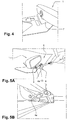
- the figure 4 shows the prepositioning of the mirror 1 on the windshield 6 by the operator (step 1).
- Step 2 illustrated by the Figures 5A and 5B , is the introduction of the tool 8 on the foot 4 of the rearview mirror: the operator slides the hooks 15a on the protruding lugs 4a of the mirror foot 4 ( Figure 5A ), then lowers the rod 10 of the tool towards the windshield 6, until the plexiglass plate 13 bears on it ( Figure 5B ). The tilting of the actuating member of the tool (rod 10) in the direction of the windshield 6, bears the tool 8 on the windshield 6.
- Step 3 is the clipping of the mirror 1 on the base 7.
- the traction of the mirror foot 4 along the base 7 is effected by a rotational movement of the actuating member (rod 10). This rotation is controlled by a quarter-turn rotational movement of the handle 11.
- the finger 9 of the tool 8 remains in fixed support on the base 7.
- the hooks 15 pull the foot 4 of the rearview mirror by its lugs 4a in response to the movement of the handle.
- the mirror is clipped onto the base 7.
- Step 4 is the unlocking and removal of the tool 8.
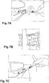
- the tool is unlocked by quarter turn rotation of a handle in the opposite direction to step 3 (Fig. 7A).
- the brackets return in their heading ( Figure 7B ).
- the tool can then be pulled out by tilting the hooks under the mirror ( Figure 7C ).
Landscapes
- Engineering & Computer Science (AREA)
- Mechanical Engineering (AREA)
- Rear-View Mirror Devices That Are Mounted On The Exterior Of The Vehicle (AREA)
- Vehicle Interior And Exterior Ornaments, Soundproofing, And Insulation (AREA)
Abstract
Description
- La présente invention se rapporte au montage d'un rétroviseur intérieur de véhicule automobile, sur un pare-brise.
- Plus précisément, elle a pour objet un procédé et un outil de montage d'un rétroviseur intérieur sur une embase préalablement fixée sur un pare-brise de véhicule.
- Le montage d'un rétroviseur sur un pare-brise est une opération manuelle, réalisée par un opérateur dans une usine de montage de véhicules. Le plus souvent, le rétroviseur se monte sur une embase appartenant à un support, préalablement collé sur la face intérieure du pare-brise. L'embase présente généralement des rainures d'emboîtement. L'opération principale du montage consiste à présenter le pied du rétroviseur à l'entrée des rainures, et à le faire coulisser le long de celles-ci. Ce mouvement implique un certain effort, qui peut être fourni à l'aide d'un marteau, grâce auquel l'opérateur parvient à repousser le pied sur l'embase, jusqu'à la position finale de montage.
- Pour remplacer le marteau, on a déjà proposé d'utiliser des pinces, telle que celle qui est décrite dans la publication
FR 2 950 828 - Lorsque l'espace disponible pour positionner et engager le pied du rétroviseur sur l'embase est réduit, notamment à proximité du pavillon, l'usage de la pince peut devenir difficile. C'est notamment le cas lorsque ses mouvements sont gênés par des obstacles, comme des ergots ou protubérances fonctionnelles du support, pour la fixation d'appareillages divers, caméras ou autres, et des systèmes de connexion associés.
- Lorsque l'opérateur rencontre des difficultés pour introduire le pied du rétroviseur sur l'embase avec une pince, il lui arrive d'exercer son effort de poussée dans une mauvaise direction, avec un risque d'arrachement de l'embase, ou pire, l'apparition de fissures sur le pare-brise.
- La présente invention propose un nouveau procédé et un nouvel outil de montage, remplaçant le marteau ou la pince connus.
- Le procédé comporte les étapes suivantes :
- prépositionnement du rétroviseur sur son embase,
- mise en place d'un outil de montage, par accochage de celui-ci sur des parties en saillie du pied de rétroviseur, et mise en appui de l'outil sur le pare-brise,
- clipsage du pied de rétroviseur sur son embase par traction le long de l'embase au moyen de l'outil, en prenant appui sur le pare-brise,
- dégagement de l'outil en position finale de montage.
- Cette méthode assure un montage aisé, et fiable, du rétroviseur sur son embase, même dans un environnement très contraint.
- Le nouvel outil comprend un doigt d'appui fixe sur le pare-brise, une tige d'actionnement mobile et un pied arrière, fixé sur une plaque d'appui sur le pare-brise, qui suit le déplacement de la tige.
- La présente invention sera mieux comprise à la lecture de la description suivante d'un mode de réalisation non limitatif de celle-ci, en se reportant aux dessins annexés, sur lesquels :
- la
figure 1 illustre l'implantation d'un rétroviseur intérieur sur la face intérieure d'un pare-brise, - la
figure 2 montre un exemple de support de rétroviseur sur pare-brise, - les
figures 3A à 3D sont respectivement une vue de dessus, une vue de côté, une vue de dessous du nouvel outil proposé, et une vue de l'ensemble au travers du pare-brise, - la
figure 4 illustre une première étape du procédé, - les
figures 5A à 5C une deuxième étape, - les
figures 6A à 6C une troisième étape, et - les
figures 7A, 7B, 7C sa quatrième et dernière étape. - Sur la
figure 1 , on voit un rétroviseur intérieur de véhicule 1, comprenant un miroir 2, dans son boîtier 3, et un pied 4. Le pied du rétroviseur est monté sur un support 5, collé sur la face intérieure du pare-brise 6, à proximité de son bord supérieur 6a. Il présente en saillie, des ergots d'accrochage laréraux 4a. - La
figure 2 est une vue du support 5, en place sur le pare-brise 6, sans le rétroviseur. Outre l'embase de fixation 7 du rétroviseur, on distingue l'emplacement 5a d'une caméra (non représentée), son support 5b, et l'emplacement 5c d'un capteur de pluie (non représenté). - L'outil proposé 8, est illustré par les
figures 3A à 3D . Il comprend un doigt d'appui fixe 9 sur le pare-brise, et une tige d'actionnement mobile 10, prolongée à angle droit par une poignée 11. Un pied arrière 12, fixé sur une plaque en plexiglas 13 suit le déplacement de la tige 10 vers le bas pour placer la plaque 13 contre le pare-brise 6, de manière à donner à l'outil 8 un appui plan lors du déplacement du pied de rétroviseur sur l'embase 7. L'outil 8 comprend deux traverses 14 et deux bras latéraux 15, prolongés vers l'extérieur par deux crochets 15a. Ces crochets permettent à l'outil de saisir le pied 4 du rétroviseur, et de le tirer jusqu'à sa position de montage. Les bras 15 présentent deux ouvertures allongées 15b visibles sur lafigure 3B . Ces ouvertures permettent au pied de l'outil 12, de descendre, avec la tige 10 et la plaque 13, sur le pare-brise 6. - Sur la
figure 3C , on distingue une fente de guidage incurvée 12a à l'intérieur du pied 12. Cette fente reçoit un doigt de traction 10a, solidaire de la tige d'actionnement 10. Le guidage du doigt 10a dans la fente 12a permet à la tige 10 de tirer vers l'arrière le rétroviseur, jusqu'à sa position finale, lors d'un mouvement de rotation quart de tour de la poignée 11. - Sur la vue de dessous de la
figure 3D , on voit l'embase de fixation 7. Le pied de rétroviseur 4 est engagé partiellement sur celle-ci. On reconnaît le doigt d'appui 9 l'outil 8, son pied 12, avec la fente de guidage 12a et le doigt 10a, ainsi que la plaque de plexiglas 13. - Le procédé de montage comporte les étapes suivantes :
- prépositionnement du rétroviseur 1 sur son embase,
- mise en place de l'outil de montage 8, par accochage de celui-ci sur des parties en saillie (ergots 4a) du pied de rétroviseur 4a, et mise en appui de l'outil sur le pare-brise,
- clipsage du pied de rétroviseur 4 sur l'embase 7 par traction le long de l'embase au moyen de l'outil 8, en prenant appui sur le pare-brise 6,
- dégagement de l'outil 8, et du pied de rétroviseur 4, en position finale de montage.
- La
figure 4 montre le prépositionnement du rétroviseur 1 sur le pare-brise 6 par l'opérateur (étape 1). - L'étape 2, illustrée par les
figures 5A et 5B , est la mise en place de l'outil 8 sur le pied 4 du rétroviseur : l'opérateur glisse les crochets 15a sur les ergots en saillie 4a du pied de rétroviseur 4 (figure 5A ), puis abaisse la tige 10 de l'outil vers le pare-brise 6, jusqu'à ce que la plaque de plexiglas 13 vienne en appui sur celui-ci (figure 5B ). Le basculement de l'organe d'actionnement de l'outil (tige 10) en direction du pare-brise 6, met en appui l'outil 8 sur le pare-brise 6. - L'étape 3 (
figures 6A à 6C ) est le clipsage du rétroviseur 1 sur l'embase 7. La traction du pied de rétroviseur 4 le long de l'embase 7 s'effectue par un mouvement de rotation de l'organe d'actionnement (tige 10). Cette rotation est commandée par un mouvement de rotation quart de tour de la poignée 11. - Au cours de ce déplacement, le doigt 9 de l'outil 8 reste en appui fixe sur l'embase 7. Les crochets 15 tirent le pied 4 du rétroviseur par ses ergots 4a en réponse au mouvement de la poignée. En fin de course, le rétroviseur est clippé sur l'embase 7.
- L'étape 4 (
figures 7A à 7C ) est le déverrouillage et l'enlèvement de l'outil 8. On déverrouille l'outil par une rotation quart de tour de a poignée dans le sens inverse de l'étape 3 (figue 7A). Les crochets reviennent dans leur positio intitiale (figure 7B ). on peut alors ressortir l'outil en basculant les crochets sous le rétroviseur (figure 7C ). - Les intérêts liés à l'utilisation de l'outil proposé sont multiples. Parmi ceux-ci, on peut noter :
- la garantie d'une bonne fixation du rétroviseur sur le pare-brise, en réduisant au minimum les efforts appliqu&és sur les pièces,
- les respect de l'ensemble des règles de métier imposées au montage de pièces en usine,
- l'absence de risque de dégradation du pre-brise ou d'arrachement de l'embase, grâce à la continuité de l'effort imposé aux pièces lors du mouvement quart de tour de la poignée,
- l'absence de risque de dégradation de composants associés au support de rétroviseur (tels que des câblages électriques dans le cas de rétroviseurs électrochromes),
- la réduction de la diversité d'outillage selon les usines de montage et des véhicules produits,
- l'amélioration de l'ergonomie sur le poste de l'opérateur, par rapport aux outils utilisés antérieurement.
Claims (10)
- Procédé de montage d'un rétroviseur intérieur (1) sur une embase (7) préalablement fixée sur un pare-brise (6) de véhicule, caractérisé en ce qu'il comporte les étapes suivantes :- prépositionnement du rétroviseur (1) sur son embase,- mise en place d'un outil de montage (8), par accochage de celui-ci sur des parties en saillie (4a) du pied de rétroviseur (4a), et mise en appui de l'outil sur le pare-brise,- clipsage du pied de rétroviseur (4) sur son embase par traction le long de l'embase au moyen de l'outil, en prenant appui sur le pare-brise (6),- dégagement de l'outil en position finale de montage.
- Procédé de montage selon la revendication 1, caractérisé en ce que la mise en place de l'outil de montage (8) s'effectue en glissant des crochets (15a) de l'outil sous des parties en saillie du pied de rétroviseur, puis en basculant un organe d'actionnement (10) de l'outil en direction du pare-brise (6), pour mettre en appui l'outil sur le pare-brise.
- Procédé de montage selon la revendication 2, caractérisé en ce que la traction du pied de rétroviseur (4) le long de l'embase (7), s'effectue par un mouvement de rotation de l'orgne d'actionnement (10).
- Procédé de montage selon la revendication 2 ou 3, caractérisé en ce que le dégagement de l'outil s'effectue en basculant l'organe d'actionnement à l'écart du pare-brise, avant de retirer les crochets des parties en saillie.
- Procédé de montage selon la revendication 4, caractérisé en ce que les crochets (15a) sont replacés à leur position intitiale par rapport à l'outil (8), avant de retirer celui-ci.
- Outil de montage (8) de rétroviseur intérieur conformément à l'une des revendications précédentes, caractérisé en ce qu'il comprend un doigt d'appui fixe (9) sur le pare-brise (6), une tige d'actionnement mobile (10) et un pied arrière (12) fixé sur une plaque d'appui (13) sur le pare-brise, qui suit le déplacement de la tige (10).
- Outil de montage (8) de rétroviseur intérieur selon la revendication 6, caractérisé en ce qu'il comprend deux bras latéraux (15), prolongés par deux crochets (15a) permettant à l'outil de saisir le pied de rétroviseur (4) et de le tirer jusqu'à sa position de montage.
- Outil montage (8) de rétroviseur intérieur selon la revendiction 6, ou 7, caractérisé en ce que la tige d'actionnement (10) porte une poignée (11), orientée à angle droit par rapport à celle-ci.
- Outil de montage (8) de rétroviseur intérieur selon la revendication 6, 7 ou 8, caractérisé en ce que le pied (12) présente une fente de guidage (12a) pour un un doigt de traction (10a), solidaire de la tige d'actionnement (10).
- Outil de montage (8) de rétroviseur intérieur selon la revendication 9, caractérisé en ce que le guidage du doigt (10a) dans la fente (12a), permet à la tige (10) de tirer le pied de rétroviseur (4) jusqu'à sa position finale de montage, lors d'un mouvement de rotation de la poignée (11).
Applications Claiming Priority (1)
| Application Number | Priority Date | Filing Date | Title |
|---|---|---|---|
| FR1854059A FR3081145B1 (fr) | 2018-05-15 | 2018-05-15 | Procede et outil de montage d'un retroviseur interieur sur un pare brise |
Publications (2)
| Publication Number | Publication Date |
|---|---|
| EP3569361A1 true EP3569361A1 (fr) | 2019-11-20 |
| EP3569361B1 EP3569361B1 (fr) | 2022-02-23 |
Family
ID=62751167
Family Applications (1)
| Application Number | Title | Priority Date | Filing Date |
|---|---|---|---|
| EP19173911.9A Active EP3569361B1 (fr) | 2018-05-15 | 2019-05-10 | Procédé et outil de montage d'un retroviseur interieur sur un pare brise |
Country Status (2)
| Country | Link |
|---|---|
| EP (1) | EP3569361B1 (fr) |
| FR (1) | FR3081145B1 (fr) |
Cited By (1)
| Publication number | Priority date | Publication date | Assignee | Title |
|---|---|---|---|---|
| IT202300004836A1 (it) * | 2023-03-14 | 2024-09-14 | Gema S R L | Dispositivo per svincolare un elemento da una struttura |
Citations (3)
| Publication number | Priority date | Publication date | Assignee | Title |
|---|---|---|---|---|
| EP2072187A1 (fr) * | 2007-12-19 | 2009-06-24 | Renault S.A.S. | Pince de montage d'un retroviseur |
| FR2926042A1 (fr) * | 2008-01-03 | 2009-07-10 | Peugeot Citroen Automobiles Sa | Dispositif d'aide au montage d'un retroviseur interieur |
| FR2950828A1 (fr) | 2009-10-07 | 2011-04-08 | Peugeot Citroen Automobiles Sa | Outil pour la fixation d'un retroviseur interieur sur un support fixe sur un pare-brise de vehicule automobile |
-
2018
- 2018-05-15 FR FR1854059A patent/FR3081145B1/fr not_active Expired - Fee Related
-
2019
- 2019-05-10 EP EP19173911.9A patent/EP3569361B1/fr active Active
Patent Citations (3)
| Publication number | Priority date | Publication date | Assignee | Title |
|---|---|---|---|---|
| EP2072187A1 (fr) * | 2007-12-19 | 2009-06-24 | Renault S.A.S. | Pince de montage d'un retroviseur |
| FR2926042A1 (fr) * | 2008-01-03 | 2009-07-10 | Peugeot Citroen Automobiles Sa | Dispositif d'aide au montage d'un retroviseur interieur |
| FR2950828A1 (fr) | 2009-10-07 | 2011-04-08 | Peugeot Citroen Automobiles Sa | Outil pour la fixation d'un retroviseur interieur sur un support fixe sur un pare-brise de vehicule automobile |
Cited By (2)
| Publication number | Priority date | Publication date | Assignee | Title |
|---|---|---|---|---|
| IT202300004836A1 (it) * | 2023-03-14 | 2024-09-14 | Gema S R L | Dispositivo per svincolare un elemento da una struttura |
| WO2024189660A1 (fr) * | 2023-03-14 | 2024-09-19 | Gema S.R.L. | Dispositif de libération d'un élément d'une structure |
Also Published As
| Publication number | Publication date |
|---|---|
| FR3081145B1 (fr) | 2020-05-08 |
| FR3081145A1 (fr) | 2019-11-22 |
| EP3569361B1 (fr) | 2022-02-23 |
Similar Documents
| Publication | Publication Date | Title |
|---|---|---|
| EP0362026B1 (fr) | Dispositif d'accouplement fixe entre une vitre et un mécanisme de lève-vitre dans un véhicule | |
| EP1545947B1 (fr) | Agencement de fixation d'un balai d'essuie glace sur un bras | |
| FR2947765A1 (fr) | Dispositif de toit ouvrant notamment pour vehicule automobile | |
| EP3569361B1 (fr) | Procédé et outil de montage d'un retroviseur interieur sur un pare brise | |
| EP2930106A1 (fr) | Système de fixation d'un objet sur un rail d'un support | |
| EP3835523A1 (fr) | Dispositif de fermeture provisoire d'un element ouvrant sur un element de support | |
| EP0362027A1 (fr) | Dispositif d'accouplement coulissant entre une vitre et un mécanisme de lève-vitre dans un véhicule | |
| EP0178998A1 (fr) | Dispositif de levage de véhicule du type "cric" | |
| EP3601025B1 (fr) | Luge de preparation et procede d'assemblage pour un vehicule | |
| FR2851948A1 (fr) | Dispositif d'assemblage d'un premier et d'un deuxieme tuyau | |
| EP4043290B1 (fr) | Dispositif de maintien d'un appareil électronique portable dans un véhicule automobile | |
| EP4086137B1 (fr) | Outil de déplacement d'un attelage d'un véhicule ferroviaire, ensemble et procédé d'utilisation associés | |
| EP1747935A2 (fr) | Ensemble coulissant et ensemble de mobilier coulissant pour habitacle de véhicule | |
| FR3019600A1 (fr) | Systeme de fixation d'un objet dans un rail d'un support | |
| EP2208841A1 (fr) | Béquille manuelle de maintien d'ouverture d'un ouvrant de véhicule | |
| EP0430759B1 (fr) | Dispositif de commande pour l'actionnement d'un frein de stationnement d'un véhicule automobile | |
| EP3590623B1 (fr) | Outil d'anglage et procédé de pliage mis en oeuvre par un tel outil | |
| EP2072187A1 (fr) | Pince de montage d'un retroviseur | |
| FR3055254A1 (fr) | Dispositif de guidage d’une vitre mobile montee dans la porte d’un vehicule, notamment automobile | |
| EP2952269B1 (fr) | Dispositif pour sécuriser le coulisseau d'un outil de presse, monté mobile entre une position reculée et une position de travail | |
| EP1756387B1 (fr) | Fixation de manivelle de mecanisme de leve vitre | |
| EP3156576A1 (fr) | Dispositif leve-vitre pour un vehicule automobile, porte de vehicule automobile et procede d'assemblage correspondants | |
| FR2956997A1 (fr) | Dispositif de pianotage d'outils avec un seul actionneur | |
| FR2846474A1 (fr) | Systeme de raccordement electrique d'un sous-ensemble d'un vehicule | |
| FR2911901A1 (fr) | Dispositif de suspension de panneau coulissant |
Legal Events
| Date | Code | Title | Description |
|---|---|---|---|
| PUAI | Public reference made under article 153(3) epc to a published international application that has entered the european phase |
Free format text: ORIGINAL CODE: 0009012 |
|
| STAA | Information on the status of an ep patent application or granted ep patent |
Free format text: STATUS: THE APPLICATION HAS BEEN PUBLISHED |
|
| AK | Designated contracting states |
Kind code of ref document: A1 Designated state(s): AL AT BE BG CH CY CZ DE DK EE ES FI FR GB GR HR HU IE IS IT LI LT LU LV MC MK MT NL NO PL PT RO RS SE SI SK SM TR |
|
| AX | Request for extension of the european patent |
Extension state: BA ME |
|
| STAA | Information on the status of an ep patent application or granted ep patent |
Free format text: STATUS: REQUEST FOR EXAMINATION WAS MADE |
|
| 17P | Request for examination filed |
Effective date: 20200504 |
|
| RBV | Designated contracting states (corrected) |
Designated state(s): AL AT BE BG CH CY CZ DE DK EE ES FI FR GB GR HR HU IE IS IT LI LT LU LV MC MK MT NL NO PL PT RO RS SE SI SK SM TR |
|
| RIC1 | Information provided on ipc code assigned before grant |
Ipc: B25B 27/14 20060101ALI20210804BHEP Ipc: B25B 27/02 20060101ALI20210804BHEP Ipc: B25B 27/00 20060101AFI20210804BHEP |
|
| GRAP | Despatch of communication of intention to grant a patent |
Free format text: ORIGINAL CODE: EPIDOSNIGR1 |
|
| STAA | Information on the status of an ep patent application or granted ep patent |
Free format text: STATUS: GRANT OF PATENT IS INTENDED |
|
| INTG | Intention to grant announced |
Effective date: 20210917 |
|
| GRAS | Grant fee paid |
Free format text: ORIGINAL CODE: EPIDOSNIGR3 |
|
| GRAA | (expected) grant |
Free format text: ORIGINAL CODE: 0009210 |
|
| STAA | Information on the status of an ep patent application or granted ep patent |
Free format text: STATUS: THE PATENT HAS BEEN GRANTED |
|
| REG | Reference to a national code |
Ref country code: DE Ref legal event code: R081 Ref document number: 602019011777 Country of ref document: DE Owner name: RENAULT S.A.S., FR Free format text: FORMER OWNER: RENAULT S.A.S., BOULOGNE BILLANCOURT, FR |
|
| AK | Designated contracting states |
Kind code of ref document: B1 Designated state(s): AL AT BE BG CH CY CZ DE DK EE ES FI FR GB GR HR HU IE IS IT LI LT LU LV MC MK MT NL NO PL PT RO RS SE SI SK SM TR |
|
| REG | Reference to a national code |
Ref country code: GB Ref legal event code: FG4D Free format text: NOT ENGLISH |
|
| REG | Reference to a national code |
Ref country code: CH Ref legal event code: EP |
|
| RAP4 | Party data changed (patent owner data changed or rights of a patent transferred) |
Owner name: RENAULT S.A.S |
|
| REG | Reference to a national code |
Ref country code: AT Ref legal event code: REF Ref document number: 1470079 Country of ref document: AT Kind code of ref document: T Effective date: 20220315 |
|
| REG | Reference to a national code |
Ref country code: IE Ref legal event code: FG4D Free format text: LANGUAGE OF EP DOCUMENT: FRENCH |
|
| REG | Reference to a national code |
Ref country code: DE Ref legal event code: R096 Ref document number: 602019011777 Country of ref document: DE |
|
| REG | Reference to a national code |
Ref country code: LT Ref legal event code: MG9D |
|
| REG | Reference to a national code |
Ref country code: NL Ref legal event code: MP Effective date: 20220223 |
|
| REG | Reference to a national code |
Ref country code: AT Ref legal event code: MK05 Ref document number: 1470079 Country of ref document: AT Kind code of ref document: T Effective date: 20220223 |
|
| RAP4 | Party data changed (patent owner data changed or rights of a patent transferred) |
Owner name: RENAULT S.A.S |
|
| PG25 | Lapsed in a contracting state [announced via postgrant information from national office to epo] |
Ref country code: SE Free format text: LAPSE BECAUSE OF FAILURE TO SUBMIT A TRANSLATION OF THE DESCRIPTION OR TO PAY THE FEE WITHIN THE PRESCRIBED TIME-LIMIT Effective date: 20220223 Ref country code: RS Free format text: LAPSE BECAUSE OF FAILURE TO SUBMIT A TRANSLATION OF THE DESCRIPTION OR TO PAY THE FEE WITHIN THE PRESCRIBED TIME-LIMIT Effective date: 20220223 Ref country code: PT Free format text: LAPSE BECAUSE OF FAILURE TO SUBMIT A TRANSLATION OF THE DESCRIPTION OR TO PAY THE FEE WITHIN THE PRESCRIBED TIME-LIMIT Effective date: 20220623 Ref country code: NO Free format text: LAPSE BECAUSE OF FAILURE TO SUBMIT A TRANSLATION OF THE DESCRIPTION OR TO PAY THE FEE WITHIN THE PRESCRIBED TIME-LIMIT Effective date: 20220523 Ref country code: NL Free format text: LAPSE BECAUSE OF FAILURE TO SUBMIT A TRANSLATION OF THE DESCRIPTION OR TO PAY THE FEE WITHIN THE PRESCRIBED TIME-LIMIT Effective date: 20220223 Ref country code: LT Free format text: LAPSE BECAUSE OF FAILURE TO SUBMIT A TRANSLATION OF THE DESCRIPTION OR TO PAY THE FEE WITHIN THE PRESCRIBED TIME-LIMIT Effective date: 20220223 Ref country code: HR Free format text: LAPSE BECAUSE OF FAILURE TO SUBMIT A TRANSLATION OF THE DESCRIPTION OR TO PAY THE FEE WITHIN THE PRESCRIBED TIME-LIMIT Effective date: 20220223 Ref country code: ES Free format text: LAPSE BECAUSE OF FAILURE TO SUBMIT A TRANSLATION OF THE DESCRIPTION OR TO PAY THE FEE WITHIN THE PRESCRIBED TIME-LIMIT Effective date: 20220223 Ref country code: BG Free format text: LAPSE BECAUSE OF FAILURE TO SUBMIT A TRANSLATION OF THE DESCRIPTION OR TO PAY THE FEE WITHIN THE PRESCRIBED TIME-LIMIT Effective date: 20220523 |
|
| PG25 | Lapsed in a contracting state [announced via postgrant information from national office to epo] |
Ref country code: PL Free format text: LAPSE BECAUSE OF FAILURE TO SUBMIT A TRANSLATION OF THE DESCRIPTION OR TO PAY THE FEE WITHIN THE PRESCRIBED TIME-LIMIT Effective date: 20220223 Ref country code: LV Free format text: LAPSE BECAUSE OF FAILURE TO SUBMIT A TRANSLATION OF THE DESCRIPTION OR TO PAY THE FEE WITHIN THE PRESCRIBED TIME-LIMIT Effective date: 20220223 Ref country code: GR Free format text: LAPSE BECAUSE OF FAILURE TO SUBMIT A TRANSLATION OF THE DESCRIPTION OR TO PAY THE FEE WITHIN THE PRESCRIBED TIME-LIMIT Effective date: 20220524 Ref country code: FI Free format text: LAPSE BECAUSE OF FAILURE TO SUBMIT A TRANSLATION OF THE DESCRIPTION OR TO PAY THE FEE WITHIN THE PRESCRIBED TIME-LIMIT Effective date: 20220223 Ref country code: AT Free format text: LAPSE BECAUSE OF FAILURE TO SUBMIT A TRANSLATION OF THE DESCRIPTION OR TO PAY THE FEE WITHIN THE PRESCRIBED TIME-LIMIT Effective date: 20220223 |
|
| PG25 | Lapsed in a contracting state [announced via postgrant information from national office to epo] |
Ref country code: IS Free format text: LAPSE BECAUSE OF FAILURE TO SUBMIT A TRANSLATION OF THE DESCRIPTION OR TO PAY THE FEE WITHIN THE PRESCRIBED TIME-LIMIT Effective date: 20220623 |
|
| PG25 | Lapsed in a contracting state [announced via postgrant information from national office to epo] |
Ref country code: SM Free format text: LAPSE BECAUSE OF FAILURE TO SUBMIT A TRANSLATION OF THE DESCRIPTION OR TO PAY THE FEE WITHIN THE PRESCRIBED TIME-LIMIT Effective date: 20220223 Ref country code: SK Free format text: LAPSE BECAUSE OF FAILURE TO SUBMIT A TRANSLATION OF THE DESCRIPTION OR TO PAY THE FEE WITHIN THE PRESCRIBED TIME-LIMIT Effective date: 20220223 Ref country code: RO Free format text: LAPSE BECAUSE OF FAILURE TO SUBMIT A TRANSLATION OF THE DESCRIPTION OR TO PAY THE FEE WITHIN THE PRESCRIBED TIME-LIMIT Effective date: 20220223 Ref country code: EE Free format text: LAPSE BECAUSE OF FAILURE TO SUBMIT A TRANSLATION OF THE DESCRIPTION OR TO PAY THE FEE WITHIN THE PRESCRIBED TIME-LIMIT Effective date: 20220223 Ref country code: DK Free format text: LAPSE BECAUSE OF FAILURE TO SUBMIT A TRANSLATION OF THE DESCRIPTION OR TO PAY THE FEE WITHIN THE PRESCRIBED TIME-LIMIT Effective date: 20220223 Ref country code: CZ Free format text: LAPSE BECAUSE OF FAILURE TO SUBMIT A TRANSLATION OF THE DESCRIPTION OR TO PAY THE FEE WITHIN THE PRESCRIBED TIME-LIMIT Effective date: 20220223 |
|
| REG | Reference to a national code |
Ref country code: DE Ref legal event code: R097 Ref document number: 602019011777 Country of ref document: DE |
|
| PG25 | Lapsed in a contracting state [announced via postgrant information from national office to epo] |
Ref country code: AL Free format text: LAPSE BECAUSE OF FAILURE TO SUBMIT A TRANSLATION OF THE DESCRIPTION OR TO PAY THE FEE WITHIN THE PRESCRIBED TIME-LIMIT Effective date: 20220223 |
|
| PLBE | No opposition filed within time limit |
Free format text: ORIGINAL CODE: 0009261 |
|
| REG | Reference to a national code |
Ref country code: CH Ref legal event code: PL |
|
| STAA | Information on the status of an ep patent application or granted ep patent |
Free format text: STATUS: NO OPPOSITION FILED WITHIN TIME LIMIT |
|
| REG | Reference to a national code |
Ref country code: BE Ref legal event code: MM Effective date: 20220531 |
|
| PG25 | Lapsed in a contracting state [announced via postgrant information from national office to epo] |
Ref country code: MC Free format text: LAPSE BECAUSE OF FAILURE TO SUBMIT A TRANSLATION OF THE DESCRIPTION OR TO PAY THE FEE WITHIN THE PRESCRIBED TIME-LIMIT Effective date: 20220223 Ref country code: LU Free format text: LAPSE BECAUSE OF NON-PAYMENT OF DUE FEES Effective date: 20220510 Ref country code: LI Free format text: LAPSE BECAUSE OF NON-PAYMENT OF DUE FEES Effective date: 20220531 Ref country code: CH Free format text: LAPSE BECAUSE OF NON-PAYMENT OF DUE FEES Effective date: 20220531 |
|
| 26N | No opposition filed |
Effective date: 20221124 |
|
| PG25 | Lapsed in a contracting state [announced via postgrant information from national office to epo] |
Ref country code: SI Free format text: LAPSE BECAUSE OF FAILURE TO SUBMIT A TRANSLATION OF THE DESCRIPTION OR TO PAY THE FEE WITHIN THE PRESCRIBED TIME-LIMIT Effective date: 20220223 |
|
| PG25 | Lapsed in a contracting state [announced via postgrant information from national office to epo] |
Ref country code: IE Free format text: LAPSE BECAUSE OF NON-PAYMENT OF DUE FEES Effective date: 20220510 |
|
| PG25 | Lapsed in a contracting state [announced via postgrant information from national office to epo] |
Ref country code: BE Free format text: LAPSE BECAUSE OF NON-PAYMENT OF DUE FEES Effective date: 20220531 |
|
| P01 | Opt-out of the competence of the unified patent court (upc) registered |
Effective date: 20230608 |
|
| PG25 | Lapsed in a contracting state [announced via postgrant information from national office to epo] |
Ref country code: IT Free format text: LAPSE BECAUSE OF FAILURE TO SUBMIT A TRANSLATION OF THE DESCRIPTION OR TO PAY THE FEE WITHIN THE PRESCRIBED TIME-LIMIT Effective date: 20220223 |
|
| PG25 | Lapsed in a contracting state [announced via postgrant information from national office to epo] |
Ref country code: HU Free format text: LAPSE BECAUSE OF FAILURE TO SUBMIT A TRANSLATION OF THE DESCRIPTION OR TO PAY THE FEE WITHIN THE PRESCRIBED TIME-LIMIT; INVALID AB INITIO Effective date: 20190510 |
|
| PG25 | Lapsed in a contracting state [announced via postgrant information from national office to epo] |
Ref country code: MK Free format text: LAPSE BECAUSE OF FAILURE TO SUBMIT A TRANSLATION OF THE DESCRIPTION OR TO PAY THE FEE WITHIN THE PRESCRIBED TIME-LIMIT Effective date: 20220223 Ref country code: CY Free format text: LAPSE BECAUSE OF FAILURE TO SUBMIT A TRANSLATION OF THE DESCRIPTION OR TO PAY THE FEE WITHIN THE PRESCRIBED TIME-LIMIT Effective date: 20220223 |
|
| PG25 | Lapsed in a contracting state [announced via postgrant information from national office to epo] |
Ref country code: TR Free format text: LAPSE BECAUSE OF FAILURE TO SUBMIT A TRANSLATION OF THE DESCRIPTION OR TO PAY THE FEE WITHIN THE PRESCRIBED TIME-LIMIT Effective date: 20220223 |
|
| PG25 | Lapsed in a contracting state [announced via postgrant information from national office to epo] |
Ref country code: MT Free format text: LAPSE BECAUSE OF FAILURE TO SUBMIT A TRANSLATION OF THE DESCRIPTION OR TO PAY THE FEE WITHIN THE PRESCRIBED TIME-LIMIT Effective date: 20220223 |
|
| PGFP | Annual fee paid to national office [announced via postgrant information from national office to epo] |
Ref country code: DE Payment date: 20250521 Year of fee payment: 7 |
|
| PGFP | Annual fee paid to national office [announced via postgrant information from national office to epo] |
Ref country code: GB Payment date: 20250527 Year of fee payment: 7 |
|
| PGFP | Annual fee paid to national office [announced via postgrant information from national office to epo] |
Ref country code: FR Payment date: 20250528 Year of fee payment: 7 |