EP3569334A1 - Verfahren zur herstellung eines bauteils - Google Patents
Verfahren zur herstellung eines bauteils Download PDFInfo
- Publication number
- EP3569334A1 EP3569334A1 EP19174262.6A EP19174262A EP3569334A1 EP 3569334 A1 EP3569334 A1 EP 3569334A1 EP 19174262 A EP19174262 A EP 19174262A EP 3569334 A1 EP3569334 A1 EP 3569334A1
- Authority
- EP
- European Patent Office
- Prior art keywords
- component layer
- component
- friction pin
- metal material
- layer
- Prior art date
- Legal status (The legal status is an assumption and is not a legal conclusion. Google has not performed a legal analysis and makes no representation as to the accuracy of the status listed.)
- Granted
Links
Images


Classifications
-
- B—PERFORMING OPERATIONS; TRANSPORTING
- B29—WORKING OF PLASTICS; WORKING OF SUBSTANCES IN A PLASTIC STATE IN GENERAL
- B29C—SHAPING OR JOINING OF PLASTICS; SHAPING OF MATERIAL IN A PLASTIC STATE, NOT OTHERWISE PROVIDED FOR; AFTER-TREATMENT OF THE SHAPED PRODUCTS, e.g. REPAIRING
- B29C64/00—Additive manufacturing, i.e. manufacturing of three-dimensional [3D] objects by additive deposition, additive agglomeration or additive layering, e.g. by 3D printing, stereolithography or selective laser sintering
- B29C64/10—Processes of additive manufacturing
- B29C64/141—Processes of additive manufacturing using only solid materials
-
- B—PERFORMING OPERATIONS; TRANSPORTING
- B22—CASTING; POWDER METALLURGY
- B22F—WORKING METALLIC POWDER; MANUFACTURE OF ARTICLES FROM METALLIC POWDER; MAKING METALLIC POWDER; APPARATUS OR DEVICES SPECIALLY ADAPTED FOR METALLIC POWDER
- B22F10/00—Additive manufacturing of workpieces or articles from metallic powder
-
- B—PERFORMING OPERATIONS; TRANSPORTING
- B22—CASTING; POWDER METALLURGY
- B22F—WORKING METALLIC POWDER; MANUFACTURE OF ARTICLES FROM METALLIC POWDER; MAKING METALLIC POWDER; APPARATUS OR DEVICES SPECIALLY ADAPTED FOR METALLIC POWDER
- B22F10/00—Additive manufacturing of workpieces or articles from metallic powder
- B22F10/20—Direct sintering or melting
- B22F10/22—Direct deposition of molten metal
-
- B—PERFORMING OPERATIONS; TRANSPORTING
- B22—CASTING; POWDER METALLURGY
- B22F—WORKING METALLIC POWDER; MANUFACTURE OF ARTICLES FROM METALLIC POWDER; MAKING METALLIC POWDER; APPARATUS OR DEVICES SPECIALLY ADAPTED FOR METALLIC POWDER
- B22F10/00—Additive manufacturing of workpieces or articles from metallic powder
- B22F10/60—Treatment of workpieces or articles after build-up
- B22F10/66—Treatment of workpieces or articles after build-up by mechanical means
-
- B—PERFORMING OPERATIONS; TRANSPORTING
- B22—CASTING; POWDER METALLURGY
- B22F—WORKING METALLIC POWDER; MANUFACTURE OF ARTICLES FROM METALLIC POWDER; MAKING METALLIC POWDER; APPARATUS OR DEVICES SPECIALLY ADAPTED FOR METALLIC POWDER
- B22F10/00—Additive manufacturing of workpieces or articles from metallic powder
- B22F10/80—Data acquisition or data processing
- B22F10/85—Data acquisition or data processing for controlling or regulating additive manufacturing processes
-
- B—PERFORMING OPERATIONS; TRANSPORTING
- B22—CASTING; POWDER METALLURGY
- B22F—WORKING METALLIC POWDER; MANUFACTURE OF ARTICLES FROM METALLIC POWDER; MAKING METALLIC POWDER; APPARATUS OR DEVICES SPECIALLY ADAPTED FOR METALLIC POWDER
- B22F12/00—Apparatus or devices specially adapted for additive manufacturing; Auxiliary means for additive manufacturing; Combinations of additive manufacturing apparatus or devices with other processing apparatus or devices
-
- B—PERFORMING OPERATIONS; TRANSPORTING
- B22—CASTING; POWDER METALLURGY
- B22F—WORKING METALLIC POWDER; MANUFACTURE OF ARTICLES FROM METALLIC POWDER; MAKING METALLIC POWDER; APPARATUS OR DEVICES SPECIALLY ADAPTED FOR METALLIC POWDER
- B22F12/00—Apparatus or devices specially adapted for additive manufacturing; Auxiliary means for additive manufacturing; Combinations of additive manufacturing apparatus or devices with other processing apparatus or devices
- B22F12/80—Plants, production lines or modules
- B22F12/82—Combination of additive manufacturing apparatus or devices with other processing apparatus or devices
-
- B—PERFORMING OPERATIONS; TRANSPORTING
- B22—CASTING; POWDER METALLURGY
- B22F—WORKING METALLIC POWDER; MANUFACTURE OF ARTICLES FROM METALLIC POWDER; MAKING METALLIC POWDER; APPARATUS OR DEVICES SPECIALLY ADAPTED FOR METALLIC POWDER
- B22F3/00—Manufacture of workpieces or articles from metallic powder characterised by the manner of compacting or sintering; Apparatus specially adapted therefor ; Presses and furnaces
- B22F3/12—Both compacting and sintering
- B22F3/16—Both compacting and sintering in successive or repeated steps
- B22F3/164—Partial deformation or calibration
- B22F3/168—Local deformation
-
- B—PERFORMING OPERATIONS; TRANSPORTING
- B23—MACHINE TOOLS; METAL-WORKING NOT OTHERWISE PROVIDED FOR
- B23P—METAL-WORKING NOT OTHERWISE PROVIDED FOR; COMBINED OPERATIONS; UNIVERSAL MACHINE TOOLS
- B23P15/00—Making specific metal objects by operations not covered by a single other subclass or a group in this subclass
-
- B—PERFORMING OPERATIONS; TRANSPORTING
- B23—MACHINE TOOLS; METAL-WORKING NOT OTHERWISE PROVIDED FOR
- B23P—METAL-WORKING NOT OTHERWISE PROVIDED FOR; COMBINED OPERATIONS; UNIVERSAL MACHINE TOOLS
- B23P17/00—Metal-working operations, not covered by a single other subclass or another group in this subclass
-
- B—PERFORMING OPERATIONS; TRANSPORTING
- B23—MACHINE TOOLS; METAL-WORKING NOT OTHERWISE PROVIDED FOR
- B23P—METAL-WORKING NOT OTHERWISE PROVIDED FOR; COMBINED OPERATIONS; UNIVERSAL MACHINE TOOLS
- B23P9/00—Treating or finishing surfaces mechanically, with or without calibrating, primarily to resist wear or impact, e.g. smoothing or roughening turbine blades or bearings; Features of such surfaces not otherwise provided for, their treatment being unspecified
-
- B—PERFORMING OPERATIONS; TRANSPORTING
- B24—GRINDING; POLISHING
- B24B—MACHINES, DEVICES, OR PROCESSES FOR GRINDING OR POLISHING; DRESSING OR CONDITIONING OF ABRADING SURFACES; FEEDING OF GRINDING, POLISHING, OR LAPPING AGENTS
- B24B39/00—Burnishing machines or devices, i.e. requiring pressure members for compacting the surface zone; Accessories therefor
- B24B39/06—Burnishing machines or devices, i.e. requiring pressure members for compacting the surface zone; Accessories therefor designed for working plane surfaces
-
- B—PERFORMING OPERATIONS; TRANSPORTING
- B29—WORKING OF PLASTICS; WORKING OF SUBSTANCES IN A PLASTIC STATE IN GENERAL
- B29C—SHAPING OR JOINING OF PLASTICS; SHAPING OF MATERIAL IN A PLASTIC STATE, NOT OTHERWISE PROVIDED FOR; AFTER-TREATMENT OF THE SHAPED PRODUCTS, e.g. REPAIRING
- B29C64/00—Additive manufacturing, i.e. manufacturing of three-dimensional [3D] objects by additive deposition, additive agglomeration or additive layering, e.g. by 3D printing, stereolithography or selective laser sintering
-
- B—PERFORMING OPERATIONS; TRANSPORTING
- B29—WORKING OF PLASTICS; WORKING OF SUBSTANCES IN A PLASTIC STATE IN GENERAL
- B29C—SHAPING OR JOINING OF PLASTICS; SHAPING OF MATERIAL IN A PLASTIC STATE, NOT OTHERWISE PROVIDED FOR; AFTER-TREATMENT OF THE SHAPED PRODUCTS, e.g. REPAIRING
- B29C64/00—Additive manufacturing, i.e. manufacturing of three-dimensional [3D] objects by additive deposition, additive agglomeration or additive layering, e.g. by 3D printing, stereolithography or selective laser sintering
- B29C64/10—Processes of additive manufacturing
-
- B—PERFORMING OPERATIONS; TRANSPORTING
- B29—WORKING OF PLASTICS; WORKING OF SUBSTANCES IN A PLASTIC STATE IN GENERAL
- B29C—SHAPING OR JOINING OF PLASTICS; SHAPING OF MATERIAL IN A PLASTIC STATE, NOT OTHERWISE PROVIDED FOR; AFTER-TREATMENT OF THE SHAPED PRODUCTS, e.g. REPAIRING
- B29C64/00—Additive manufacturing, i.e. manufacturing of three-dimensional [3D] objects by additive deposition, additive agglomeration or additive layering, e.g. by 3D printing, stereolithography or selective laser sintering
- B29C64/10—Processes of additive manufacturing
- B29C64/171—Processes of additive manufacturing specially adapted for manufacturing multiple 3D objects
- B29C64/176—Sequentially
-
- B—PERFORMING OPERATIONS; TRANSPORTING
- B29—WORKING OF PLASTICS; WORKING OF SUBSTANCES IN A PLASTIC STATE IN GENERAL
- B29C—SHAPING OR JOINING OF PLASTICS; SHAPING OF MATERIAL IN A PLASTIC STATE, NOT OTHERWISE PROVIDED FOR; AFTER-TREATMENT OF THE SHAPED PRODUCTS, e.g. REPAIRING
- B29C64/00—Additive manufacturing, i.e. manufacturing of three-dimensional [3D] objects by additive deposition, additive agglomeration or additive layering, e.g. by 3D printing, stereolithography or selective laser sintering
- B29C64/10—Processes of additive manufacturing
- B29C64/171—Processes of additive manufacturing specially adapted for manufacturing multiple 3D objects
- B29C64/182—Processes of additive manufacturing specially adapted for manufacturing multiple 3D objects in parallel batches
-
- B—PERFORMING OPERATIONS; TRANSPORTING
- B29—WORKING OF PLASTICS; WORKING OF SUBSTANCES IN A PLASTIC STATE IN GENERAL
- B29C—SHAPING OR JOINING OF PLASTICS; SHAPING OF MATERIAL IN A PLASTIC STATE, NOT OTHERWISE PROVIDED FOR; AFTER-TREATMENT OF THE SHAPED PRODUCTS, e.g. REPAIRING
- B29C64/00—Additive manufacturing, i.e. manufacturing of three-dimensional [3D] objects by additive deposition, additive agglomeration or additive layering, e.g. by 3D printing, stereolithography or selective laser sintering
- B29C64/20—Apparatus for additive manufacturing; Details thereof or accessories therefor
-
- B—PERFORMING OPERATIONS; TRANSPORTING
- B29—WORKING OF PLASTICS; WORKING OF SUBSTANCES IN A PLASTIC STATE IN GENERAL
- B29C—SHAPING OR JOINING OF PLASTICS; SHAPING OF MATERIAL IN A PLASTIC STATE, NOT OTHERWISE PROVIDED FOR; AFTER-TREATMENT OF THE SHAPED PRODUCTS, e.g. REPAIRING
- B29C64/00—Additive manufacturing, i.e. manufacturing of three-dimensional [3D] objects by additive deposition, additive agglomeration or additive layering, e.g. by 3D printing, stereolithography or selective laser sintering
- B29C64/20—Apparatus for additive manufacturing; Details thereof or accessories therefor
- B29C64/205—Means for applying layers
-
- B—PERFORMING OPERATIONS; TRANSPORTING
- B29—WORKING OF PLASTICS; WORKING OF SUBSTANCES IN A PLASTIC STATE IN GENERAL
- B29C—SHAPING OR JOINING OF PLASTICS; SHAPING OF MATERIAL IN A PLASTIC STATE, NOT OTHERWISE PROVIDED FOR; AFTER-TREATMENT OF THE SHAPED PRODUCTS, e.g. REPAIRING
- B29C64/00—Additive manufacturing, i.e. manufacturing of three-dimensional [3D] objects by additive deposition, additive agglomeration or additive layering, e.g. by 3D printing, stereolithography or selective laser sintering
- B29C64/20—Apparatus for additive manufacturing; Details thereof or accessories therefor
- B29C64/227—Driving means
-
- B—PERFORMING OPERATIONS; TRANSPORTING
- B29—WORKING OF PLASTICS; WORKING OF SUBSTANCES IN A PLASTIC STATE IN GENERAL
- B29C—SHAPING OR JOINING OF PLASTICS; SHAPING OF MATERIAL IN A PLASTIC STATE, NOT OTHERWISE PROVIDED FOR; AFTER-TREATMENT OF THE SHAPED PRODUCTS, e.g. REPAIRING
- B29C64/00—Additive manufacturing, i.e. manufacturing of three-dimensional [3D] objects by additive deposition, additive agglomeration or additive layering, e.g. by 3D printing, stereolithography or selective laser sintering
- B29C64/20—Apparatus for additive manufacturing; Details thereof or accessories therefor
- B29C64/245—Platforms or substrates
-
- B—PERFORMING OPERATIONS; TRANSPORTING
- B29—WORKING OF PLASTICS; WORKING OF SUBSTANCES IN A PLASTIC STATE IN GENERAL
- B29C—SHAPING OR JOINING OF PLASTICS; SHAPING OF MATERIAL IN A PLASTIC STATE, NOT OTHERWISE PROVIDED FOR; AFTER-TREATMENT OF THE SHAPED PRODUCTS, e.g. REPAIRING
- B29C64/00—Additive manufacturing, i.e. manufacturing of three-dimensional [3D] objects by additive deposition, additive agglomeration or additive layering, e.g. by 3D printing, stereolithography or selective laser sintering
- B29C64/20—Apparatus for additive manufacturing; Details thereof or accessories therefor
- B29C64/25—Housings, e.g. machine housings
-
- B—PERFORMING OPERATIONS; TRANSPORTING
- B29—WORKING OF PLASTICS; WORKING OF SUBSTANCES IN A PLASTIC STATE IN GENERAL
- B29C—SHAPING OR JOINING OF PLASTICS; SHAPING OF MATERIAL IN A PLASTIC STATE, NOT OTHERWISE PROVIDED FOR; AFTER-TREATMENT OF THE SHAPED PRODUCTS, e.g. REPAIRING
- B29C64/00—Additive manufacturing, i.e. manufacturing of three-dimensional [3D] objects by additive deposition, additive agglomeration or additive layering, e.g. by 3D printing, stereolithography or selective laser sintering
- B29C64/20—Apparatus for additive manufacturing; Details thereof or accessories therefor
- B29C64/255—Enclosures for the building material, e.g. powder containers
-
- B—PERFORMING OPERATIONS; TRANSPORTING
- B29—WORKING OF PLASTICS; WORKING OF SUBSTANCES IN A PLASTIC STATE IN GENERAL
- B29C—SHAPING OR JOINING OF PLASTICS; SHAPING OF MATERIAL IN A PLASTIC STATE, NOT OTHERWISE PROVIDED FOR; AFTER-TREATMENT OF THE SHAPED PRODUCTS, e.g. REPAIRING
- B29C64/00—Additive manufacturing, i.e. manufacturing of three-dimensional [3D] objects by additive deposition, additive agglomeration or additive layering, e.g. by 3D printing, stereolithography or selective laser sintering
- B29C64/30—Auxiliary operations or equipment
-
- B—PERFORMING OPERATIONS; TRANSPORTING
- B29—WORKING OF PLASTICS; WORKING OF SUBSTANCES IN A PLASTIC STATE IN GENERAL
- B29C—SHAPING OR JOINING OF PLASTICS; SHAPING OF MATERIAL IN A PLASTIC STATE, NOT OTHERWISE PROVIDED FOR; AFTER-TREATMENT OF THE SHAPED PRODUCTS, e.g. REPAIRING
- B29C64/00—Additive manufacturing, i.e. manufacturing of three-dimensional [3D] objects by additive deposition, additive agglomeration or additive layering, e.g. by 3D printing, stereolithography or selective laser sintering
- B29C64/30—Auxiliary operations or equipment
- B29C64/307—Handling of material to be used in additive manufacturing
-
- B—PERFORMING OPERATIONS; TRANSPORTING
- B29—WORKING OF PLASTICS; WORKING OF SUBSTANCES IN A PLASTIC STATE IN GENERAL
- B29C—SHAPING OR JOINING OF PLASTICS; SHAPING OF MATERIAL IN A PLASTIC STATE, NOT OTHERWISE PROVIDED FOR; AFTER-TREATMENT OF THE SHAPED PRODUCTS, e.g. REPAIRING
- B29C64/00—Additive manufacturing, i.e. manufacturing of three-dimensional [3D] objects by additive deposition, additive agglomeration or additive layering, e.g. by 3D printing, stereolithography or selective laser sintering
- B29C64/30—Auxiliary operations or equipment
- B29C64/386—Data acquisition or data processing for additive manufacturing
-
- B—PERFORMING OPERATIONS; TRANSPORTING
- B29—WORKING OF PLASTICS; WORKING OF SUBSTANCES IN A PLASTIC STATE IN GENERAL
- B29C—SHAPING OR JOINING OF PLASTICS; SHAPING OF MATERIAL IN A PLASTIC STATE, NOT OTHERWISE PROVIDED FOR; AFTER-TREATMENT OF THE SHAPED PRODUCTS, e.g. REPAIRING
- B29C64/00—Additive manufacturing, i.e. manufacturing of three-dimensional [3D] objects by additive deposition, additive agglomeration or additive layering, e.g. by 3D printing, stereolithography or selective laser sintering
- B29C64/30—Auxiliary operations or equipment
- B29C64/386—Data acquisition or data processing for additive manufacturing
- B29C64/393—Data acquisition or data processing for additive manufacturing for controlling or regulating additive manufacturing processes
-
- B—PERFORMING OPERATIONS; TRANSPORTING
- B29—WORKING OF PLASTICS; WORKING OF SUBSTANCES IN A PLASTIC STATE IN GENERAL
- B29C—SHAPING OR JOINING OF PLASTICS; SHAPING OF MATERIAL IN A PLASTIC STATE, NOT OTHERWISE PROVIDED FOR; AFTER-TREATMENT OF THE SHAPED PRODUCTS, e.g. REPAIRING
- B29C64/00—Additive manufacturing, i.e. manufacturing of three-dimensional [3D] objects by additive deposition, additive agglomeration or additive layering, e.g. by 3D printing, stereolithography or selective laser sintering
- B29C64/40—Structures for supporting 3D objects during manufacture and intended to be sacrificed after completion thereof
-
- B—PERFORMING OPERATIONS; TRANSPORTING
- B33—ADDITIVE MANUFACTURING TECHNOLOGY
- B33Y—ADDITIVE MANUFACTURING, i.e. MANUFACTURING OF THREE-DIMENSIONAL [3D] OBJECTS BY ADDITIVE DEPOSITION, ADDITIVE AGGLOMERATION OR ADDITIVE LAYERING, e.g. BY 3D PRINTING, STEREOLITHOGRAPHY OR SELECTIVE LASER SINTERING
- B33Y10/00—Processes of additive manufacturing
-
- B—PERFORMING OPERATIONS; TRANSPORTING
- B33—ADDITIVE MANUFACTURING TECHNOLOGY
- B33Y—ADDITIVE MANUFACTURING, i.e. MANUFACTURING OF THREE-DIMENSIONAL [3D] OBJECTS BY ADDITIVE DEPOSITION, ADDITIVE AGGLOMERATION OR ADDITIVE LAYERING, e.g. BY 3D PRINTING, STEREOLITHOGRAPHY OR SELECTIVE LASER SINTERING
- B33Y30/00—Apparatus for additive manufacturing; Details thereof or accessories therefor
-
- B—PERFORMING OPERATIONS; TRANSPORTING
- B33—ADDITIVE MANUFACTURING TECHNOLOGY
- B33Y—ADDITIVE MANUFACTURING, i.e. MANUFACTURING OF THREE-DIMENSIONAL [3D] OBJECTS BY ADDITIVE DEPOSITION, ADDITIVE AGGLOMERATION OR ADDITIVE LAYERING, e.g. BY 3D PRINTING, STEREOLITHOGRAPHY OR SELECTIVE LASER SINTERING
- B33Y40/00—Auxiliary operations or equipment, e.g. for material handling
-
- B—PERFORMING OPERATIONS; TRANSPORTING
- B33—ADDITIVE MANUFACTURING TECHNOLOGY
- B33Y—ADDITIVE MANUFACTURING, i.e. MANUFACTURING OF THREE-DIMENSIONAL [3D] OBJECTS BY ADDITIVE DEPOSITION, ADDITIVE AGGLOMERATION OR ADDITIVE LAYERING, e.g. BY 3D PRINTING, STEREOLITHOGRAPHY OR SELECTIVE LASER SINTERING
- B33Y40/00—Auxiliary operations or equipment, e.g. for material handling
- B33Y40/10—Pre-treatment
-
- B—PERFORMING OPERATIONS; TRANSPORTING
- B33—ADDITIVE MANUFACTURING TECHNOLOGY
- B33Y—ADDITIVE MANUFACTURING, i.e. MANUFACTURING OF THREE-DIMENSIONAL [3D] OBJECTS BY ADDITIVE DEPOSITION, ADDITIVE AGGLOMERATION OR ADDITIVE LAYERING, e.g. BY 3D PRINTING, STEREOLITHOGRAPHY OR SELECTIVE LASER SINTERING
- B33Y40/00—Auxiliary operations or equipment, e.g. for material handling
- B33Y40/20—Post-treatment, e.g. curing, coating or polishing
-
- B—PERFORMING OPERATIONS; TRANSPORTING
- B33—ADDITIVE MANUFACTURING TECHNOLOGY
- B33Y—ADDITIVE MANUFACTURING, i.e. MANUFACTURING OF THREE-DIMENSIONAL [3D] OBJECTS BY ADDITIVE DEPOSITION, ADDITIVE AGGLOMERATION OR ADDITIVE LAYERING, e.g. BY 3D PRINTING, STEREOLITHOGRAPHY OR SELECTIVE LASER SINTERING
- B33Y50/00—Data acquisition or data processing for additive manufacturing
-
- B—PERFORMING OPERATIONS; TRANSPORTING
- B33—ADDITIVE MANUFACTURING TECHNOLOGY
- B33Y—ADDITIVE MANUFACTURING, i.e. MANUFACTURING OF THREE-DIMENSIONAL [3D] OBJECTS BY ADDITIVE DEPOSITION, ADDITIVE AGGLOMERATION OR ADDITIVE LAYERING, e.g. BY 3D PRINTING, STEREOLITHOGRAPHY OR SELECTIVE LASER SINTERING
- B33Y50/00—Data acquisition or data processing for additive manufacturing
- B33Y50/02—Data acquisition or data processing for additive manufacturing for controlling or regulating additive manufacturing processes
-
- B—PERFORMING OPERATIONS; TRANSPORTING
- B33—ADDITIVE MANUFACTURING TECHNOLOGY
- B33Y—ADDITIVE MANUFACTURING, i.e. MANUFACTURING OF THREE-DIMENSIONAL [3D] OBJECTS BY ADDITIVE DEPOSITION, ADDITIVE AGGLOMERATION OR ADDITIVE LAYERING, e.g. BY 3D PRINTING, STEREOLITHOGRAPHY OR SELECTIVE LASER SINTERING
- B33Y70/00—Materials specially adapted for additive manufacturing
-
- B—PERFORMING OPERATIONS; TRANSPORTING
- B33—ADDITIVE MANUFACTURING TECHNOLOGY
- B33Y—ADDITIVE MANUFACTURING, i.e. MANUFACTURING OF THREE-DIMENSIONAL [3D] OBJECTS BY ADDITIVE DEPOSITION, ADDITIVE AGGLOMERATION OR ADDITIVE LAYERING, e.g. BY 3D PRINTING, STEREOLITHOGRAPHY OR SELECTIVE LASER SINTERING
- B33Y99/00—Subject matter not provided for in other groups of this subclass
-
- B—PERFORMING OPERATIONS; TRANSPORTING
- B23—MACHINE TOOLS; METAL-WORKING NOT OTHERWISE PROVIDED FOR
- B23P—METAL-WORKING NOT OTHERWISE PROVIDED FOR; COMBINED OPERATIONS; UNIVERSAL MACHINE TOOLS
- B23P23/00—Machines or arrangements of machines for performing specified combinations of different metal-working operations not covered by a single other subclass
-
- B—PERFORMING OPERATIONS; TRANSPORTING
- B23—MACHINE TOOLS; METAL-WORKING NOT OTHERWISE PROVIDED FOR
- B23P—METAL-WORKING NOT OTHERWISE PROVIDED FOR; COMBINED OPERATIONS; UNIVERSAL MACHINE TOOLS
- B23P2700/00—Indexing scheme relating to the articles being treated, e.g. manufactured, repaired, assembled, connected or other operations covered in the subgroups
- B23P2700/12—Laminated parts
-
- B—PERFORMING OPERATIONS; TRANSPORTING
- B33—ADDITIVE MANUFACTURING TECHNOLOGY
- B33Y—ADDITIVE MANUFACTURING, i.e. MANUFACTURING OF THREE-DIMENSIONAL [3D] OBJECTS BY ADDITIVE DEPOSITION, ADDITIVE AGGLOMERATION OR ADDITIVE LAYERING, e.g. BY 3D PRINTING, STEREOLITHOGRAPHY OR SELECTIVE LASER SINTERING
- B33Y80/00—Products made by additive manufacturing
-
- Y—GENERAL TAGGING OF NEW TECHNOLOGICAL DEVELOPMENTS; GENERAL TAGGING OF CROSS-SECTIONAL TECHNOLOGIES SPANNING OVER SEVERAL SECTIONS OF THE IPC; TECHNICAL SUBJECTS COVERED BY FORMER USPC CROSS-REFERENCE ART COLLECTIONS [XRACs] AND DIGESTS
- Y02—TECHNOLOGIES OR APPLICATIONS FOR MITIGATION OR ADAPTATION AGAINST CLIMATE CHANGE
- Y02P—CLIMATE CHANGE MITIGATION TECHNOLOGIES IN THE PRODUCTION OR PROCESSING OF GOODS
- Y02P10/00—Technologies related to metal processing
- Y02P10/25—Process efficiency
Definitions
- the present invention relates to a method for producing a component, in particular a structural component for an aircraft or spacecraft.
- 3D printing process In generative or additive manufacturing processes, also commonly referred to as "3D printing process” starting from a digitized geometric model of an object, one or more starting materials are sequentially stacked in layers and solidified or cured.
- the so-called build-up welding which is often used for surface coating, can also be used as an additive manufacturing process.
- a metal material is used as the starting material, wherein the individual layers are usually applied in molten, liquid form. This results in the application of a new layer on an already prepared layer to large heat input in this already prepared and solidified layer, which can lead to grain growth in the crystal structure of the metal material of this layer.
- a component is produced by sequentially stacking layers of metal material, wherein the individual layers or layers are produced from a metal material located above its melting temperature.
- a surface of a last-produced component layer forms a base surface on which the following component layer is produced. Since the metal material from which the following Particle layer is generated, is above its melting temperature, it comes on the base surface to a large heat input into the underlying component layer.
- An idea on which the invention is based is to carry out a mechanical processing of an outer surface of a solidified, last-produced component layer on which the further component layer is produced, in order to introduce dislocations into the crystal lattice of the last-produced component layer.
- the dislocations facilitate distribution of the heat input in the device layer and inhibit grain growth of the metal material due to heat input. This leads to a significantly improved mechanical strength of the component produced.
- the mechanical processing is carried out by means of a rotating friction pin. This is pressed against the outer surface or pressed into this and drives the outer surface over the entire surface. As a result, shearing stresses are introduced into the last-produced component layer over the entire area by means of the rotating pin, as a result of which dislocations are produced in the crystal lattice of this layer.
- the rotating friction pin which presses against the outer surface, large surface pressures are achieved, whereby the shear stresses are introduced into the surface in a simple and efficient manner.
- the number of operations that is to say the number of times the friction pin has to be moved over a region of the outer surface in order to achieve a desired tension entry, can be reduced compared to a rolling of the surface, for example a single operation.
- the method is advantageously accelerated.
- Another advantage is that due to the improved heat dissipation into the existing component layer, the newly produced component layer solidifies more quickly and with more homogeneous particle sizes, as a result of which mechanical strength is improved.
- the mechanical complexity of the method is reduced by the introduction of shear stresses with a rotating friction pin, since the friction pin can be guided automatically along the surface in a simple manner, for example by means of a manipulator of an industrial robot.
- step b) is repeated after step c). Accordingly, after the production of a further component layer, the outer surface of the layer last produced is also treated by means of the rotating pin. In particular, this can also be done for a last, in relation to a construction direction of the component outermost layer on which no further component layer is generated more. This is favorable for an optional subsequent heat treatment of the component. Thus, the mechanical strength of the component is further improved.
- the axis of rotation of the friction pin extends transversely to the outer surface of the component layer and the friction pin is pressed against the outer surface of the component layer with an end face extending transversely to the axis of rotation.
- the force with which the friction pin is pressed against the outer surface acts along the axis of rotation and the friction pin is moved transversely to its axis of rotation along the outer surface.
- the axis of rotation may be perpendicular to the outer surface or slightly inclined thereto, for example by an angle between 1 degree and 10 degrees. In this way, high surface pressures are achieved with a low pressing force compared with rolling.
- the end face of the friction pin has optionally in the region of the axis of rotation a recess and a recess enclosing the contact area, which is pressed against the outer surface of the component layer.
- the recess may in particular be formed as a depression of the end face.
- the recess may also be a passage opening penetrating the friction pin as a whole along the axis of rotation.
- the abutment region of the end face can be annular.
- the abutment region is designed as an annular surface concentrically surrounding the axis of rotation of the friction pin.
- the friction pin is formed from the same metal material as the component layer, wherein the force with which the friction pin is pressed against the outer surface of the component layer is selected such that the metal material of the friction pin plasticizes in a contact region with the outer surface of the component view and applied to the outer surface of the device layer.
- the friction pin is consumed graphically during the mechanical treatment of the outer surface. Due to the frictional heat generated as a result of pressing under simultaneous rotation, the metal material of the friction pin and the metal material of the component layer is set in a plastic state. As a result, metal material is rubbed off by the friction pin and lays against the surface of the component layer or is firmly bonded thereto. Thus, simultaneously with the introduction of shear stresses, an application of material takes place, whereby the production speed of the component is further increased.
- the force with which the friction pin is pressed against the outer surface of the component layer is in a range between 0.5 kilonewtons and 10 kilonewtons. In this area, shear stresses are generated particularly evenly.
- the force with which the friction pin is pressed against the outer surface of the component layer can be in a range between 4 kilonewtons and 8 kilonewtons, preferably between 5 and 7 kilonewton.
- the friction pin is rotated at a speed in a range between 100 revolutions per minute and 10,000 revolutions per minute about the axis of rotation. In this area, shear stresses are generated particularly evenly.
- the metal material for producing the component layer is applied in a liquid state to the base surface and converted there into a solid state. Accordingly, a generation of the component layers takes place in the manner of build-up welding.
- the generation of the component layer can be effected by the melting of a wire held over the base surface of the metal material.
- the wire can be subjected to an electrical voltage and be moved in the direction of the base surface until a short circuit is formed. After adjusting the current flow is computer controlled, the power supply is interrupted and the welding wire is moved back in the opposite direction.
- the metal material is applied dropwise.
- the conversion into the solid state can take place, for example, by active cooling by means of a cooling air flow or by carrying out the process at room temperature, that is to say in a temperature range between 10 degrees Celsius and 50 degrees Celsius.
- the metal material is a titanium alloy, an aluminum alloy, a nickel alloy or a steel alloy. It can therefore be formed of one of these materials, the component layers and / or the friction pin.
- the production of the component layer takes place at a build-up speed of greater than or equal to one kilogram of metal material per hour.
- the generation of the component view can take place at a build-up speed of between 1 kilogram of metal material per hour and 3 kilograms of metal material per hour.
- a machining of the component is carried out after the generation of the component layers.
- a milling step can be carried out, in which the component receives its final outer shape.
- a heat treatment is carried out after the formation of the component layers.
- that can Be exposed component after the production of all the component layers in a heating furnace a predetermined temporal temperature profile.
- a stress relief annealing can take place.
- direction indications and axes in particular to directions and axes which relate to the course of physical structures, herein is understood to mean a course of an axis, a direction or a structure "along" another axis, direction or structure, that these, in particular the tangents resulting in a respective position of the structures each extend at an angle of less than 45 degrees, preferably less than 30 degrees, and particularly preferably parallel to one another.
- a progression of an axis, a direction or a structure is understood to be "transverse" to another axis, direction or structure, that In particular, the tangents resulting in a respective position of the structures each extend at an angle of greater than or equal to 45 degrees, preferably greater than or equal to 60 degrees, and particularly preferably perpendicular to one another.
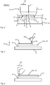
- Fig. 1 shows a first step of a method for producing a component 1.
- a sheet-like component layer 11 is produced on a base surface 10.
- the production of the component 1 is based on a digitized model of the component 1.
- This component model contains as data in particular the outer shape of the component 1 defining dimensions and information for performing the process steps explained in more detail below.
- the model of the component 1 can be transmitted as a data set to a manufacturing station 100 or the computer 5 can control the manufacturing station 100 on the basis of the model.
- Fig. 1 schematically shown a manufacturing station 100, which has a material application device 101 and a manipulator 102, to which the material application device 101 is coupled and through which the material application device 101 is movable based on the data set.
- the material application device 101 may in particular be designed as a welding device, by means of which a metal wire can be melted and applied to a surface.
- a first device layer 11 is formed on a base surface 10.
- the base surface 10 may in this case be formed in particular by a surface 2 a of a carrier plate 2.
- the component layer 11 is produced from a metal material M located above its melting temperature. This can be done, in particular, by liquefying the metal material by means of the material application device 101 and applying it in a liquid state to the base surface 10, where the metal material M solidifies.
- the material application device 101 is moved by means of the manipulator 102 along the base surface 10 in accordance with the data record of the component model, as shown in FIG Fig. 1 symbolically represented by the arrow P1.
- the material application device 101 can be controlled in such a way that at least one kilogram of metal material M per hour is applied to the base surface 10.
- the control of the material application device 101 is also carried out on the basis of the data of the component model.
- the component layer 11 can therefore take place in particular at a build-up speed of greater than or equal to one kilogram of metal material M per hour.
- the metal material M may in particular be a titanium alloy, an aluminum alloy, a nickel alloy or a steel alloy.
- Fig. 2 shows a further process step.
- the first device layer 11 has been completely produced, as shown by the Fig. 1 has been described, wherein the metal material M of the first component layer 11 is present in particular in a solidified state.
- the first component layer 11 is located with a lower surface 11b on the surface 2a of the support plate 2, which has formed in the previous process step, the base surface 10 at.
- An outer surface 11a of the first component layer 11 is located opposite to the lower surface 11b or to the surface 2a of the carrier plate 2 and thus to the base surface 10.
- Fig. 2 shows the introduction of shear stresses in the first device layer 11.
- the friction pin 3 is in this case rotated about a preferably transverse to the outer surface 11a of the first component layer 11 extending axis of rotation A and pressed with a predetermined force F to the first component layer 11.
- the friction pin 3 is moved by means of the manipulator 102 along the outer surface 11a of the component layer 11, as shown in FIG Fig. 2 symbolically represented by the arrow P2.
- the force F is directed along the axis of rotation A.
- Fig. 3 shows a plan view of the first device layer 11 during this process step.
- a region of the outer surface 11a of the component layer 11 which has already been machined mechanically by means of the friction pin 3 is shown dotted and an area still to be processed is shown as a light surface. Accordingly, the friction pin 3 is moved along the entire outer surface 11a of the component layer 11, or the component layer 11 is mechanically machined over its entire area by means of the friction pin 3.
- the force F with which the friction pin 3 is pressed against the outer surface 11a may, in particular, be in a range between 0.5 kilonewtons and 10 kilonewtons.
- a speed at which the friction pin 3 is rotated about the axis of rotation A, as in Fig. 3 symbolically represented by the arrow P3, can be in particular in a range between 100 revolutions per minute and 10,000 revolutions per minute.
- Fig. 4 is shown schematically, the introduction of shear stresses by means of the rotating friction pin 3 to form dislocations D in the metal material M of the first component layer 11, which is of great advantage for the further manufacturing process, in particular with regard to the mechanical strength of the component 1. This is explained in detail below.
- the friction pin 3 is preferably pressed against the outer surface 11a of the first component layer 11 such that the axis of rotation A of the friction pin 3 extends transversely to the outer surface 11a.
- the friction pin 3 at a first end portion 31 on an end face 30 which is pressed against the outer surface 11 a of the component layer 11.
- the end face 30 extends transversely to the axis of rotation A. With respect to a perpendicular to the rotational axis R extending radial direction R, the end face 30 has a diameter d30, which are in particular in a range between 1 mm and 10 cm can.
- a diameter of the friction pin 3 along the rotation axis D can taper towards the end face 30.
- a conical taper can also be realized differently, for example, spherically or parabolically.
- the friction pin 3 may have an optional recess 33 on the end face 30.
- the recess 33 may in particular be formed concentrically about the axis of rotation D.
- the Recess 33 surrounded by a contact area 34.
- the recess 33 may be formed as a recess of the end face 30.
- the recess 33 may also be formed as a passage opening penetrating the friction pin 3 along the axis of rotation D, as shown in FIG Fig. 9 is shown schematically.
- the contact region 34 of the end face 30 can, as in the 8 and 9 illustrated by way of example, in particular annular.
- the abutment region 34 encloses the axis of rotation D concentric.
- a friction pin 3 with a recess 33 formed as a recess and an annular abutment region 33 concentric with it or the axis of rotation D is shown, which is pressed with the force F against the outer surface 11a of the component layer 11 and rotated about the axis of rotation D to dislocations D in the component layer 11 introduce.
- Fig. 5 shows a further step of the method.
- a further, second component layer 12 is produced on the outer surface 11a of the first component layer 11, as described with reference to FIGS Fig. 1 has been described.
- the surface 2a of the carrier plate 2 no longer forms the base layer 10, but the base layer 10 is formed by the outer surface 11a of the first component layer 11 which is mechanically processed by means of the friction pin 3.
- the dislocations D generated in the preceding process step by means of the rotating friction pin 3 improve the heat dissipation of the metal material M from which the second component layer 12 is produced.
- the dislocations inhibit crystal growth due to the heat input into the first device layer 11, which consists of the production of the second component layer 12 on the serving as a base surface 10 outer surface 11a of the first component layer 11 is derived.
- the second component layer 12 are mechanically processed by means of the rotating friction pin 3, as shown by the Fig. 2 to 4 has been described.
- a further component layer (not shown) can subsequently be produced on the second component layer 12, in particular on its outer surface 12a, which is opposite to the first component layer 11, as described above.
- the outer surface 12 a of the second component layer 12 serves as the base surface 10.
- a component 1 with a multiplicity of component layers can be produced in this way, with mechanical processing of the outer surface of the component layer produced last being carried out by means of the rotating friction pin 3 after the production of a respective component layer.
- Fig. 7 schematically shows a variant of the step of introducing shear stresses in the component layer 11.
- the friction pin 3 of the same metal material M is formed as the component layer 11.
- the force F, with which the friction pin 3, in particular its end face 30, to the outer surface 11a of Component layer 11 is pressed, in this case is chosen so large that the metal material M of the Reib turns 3 is plasticized in a contact region 35 with the outer surface 11 a of the component view 11 due to the resulting frictional heat.
- the metal material M of the friction pin 3 is removed therefrom and deposited as a material layer 13 on the outer surface 11a of the component layer 11.
- FIG. 7 shows the dashed line the friction pin 3 at a later time at which already a part of the outer surface 11a of the first component layer 11 has been machined, as the representation of the friction pin 3 in full line.
- the friction pin 3 has already been removed or abraded by a length l3 along the axis of rotation D.
- This material abrasion forms the material layer 13.
- a surface 13a of the material layer 13 lying opposite the first component layer 11 forms a base surface 10 for the production of a further component layer 12, as described above.
- a further material layer 13 is produced.
- Fig. 10 shows schematically and by way of example a component 1, which was prepared as described above.
- component 1 shown by way of example has four component layers 11, 12, 13, 14 lying one above another in a construction direction B.
- the lowest layer 11 in relation to the construction direction B was determined by reference to FIG Fig. 1 explained manufactured.
- the material layer 13, as shown by Fig. 7 explained by means of the rotating friction pin 3 during the introduction of shear stresses in the first component layer 11 made.
- the component layers 12 and 14 were in turn as based on Fig. 1 respectively.
- Component 1 shown by way of example may in particular have an L-shaped external shape, as shown in FIG Fig. 3 is shown as a plan view of the first material layer 11.
- the component 1 can in particular be a structural component for an aircraft or spacecraft (not shown), for example a fuselage segment, a wing segment, a housing component or the like.
- a heat treatment can be performed.
- the component 1 can be positioned in a heating furnace 103 shown schematically and heated in this timed controlled according to a predetermined temperature profile. Due to the heat input into the component layers 11, 12, 13, 14, a modification of the crystal structure of the metal material M of the component layers 11, 12, 13, 14 carried. Due to the by means of the rotating friction pin 3 respectively in the component layers 11, 12, 13, 14 introduced Dislocations leads the heat treatment to a very homogeneous crystal structure, whereby the mechanical strength of the component 1 is increased.
- a machining of the component takes place, for example by milling or grinding. This is preferably done after the optional heat treatment, if any.
Landscapes
- Engineering & Computer Science (AREA)
- Chemical & Material Sciences (AREA)
- Materials Engineering (AREA)
- Manufacturing & Machinery (AREA)
- Mechanical Engineering (AREA)
- Physics & Mathematics (AREA)
- Optics & Photonics (AREA)
- Pressure Welding/Diffusion-Bonding (AREA)
Abstract
Description
- Die vorliegende Erfindung betrifft ein Verfahren zur Herstellung eines Bauteils, insbesondere eines Strukturbauteils für ein Luft- oder Raumfahrzeug.
- Bei generativen bzw. additiven Fertigungsverfahren, auch allgemein als "3D-Druckverfahren" bezeichnet, werden ausgehend von einem digitalisierten geometrischen Modell eines Objekts ein oder mehrere Ausgangsmaterialien sequentiell in Lagen übereinandergeschichtet und erstarrt oder ausgehärtet. Das sogenannte Auftragsschweißen, welches häufig zur Oberflächenbeschichtung eingesetzt wird, kann ebenfalls als additives Fertigungsverfahren eingesetzt werden. Hierbei wird ein Metallmaterial als Ausgangsmaterial verwendet, wobei die einzelnen Schichten üblicherweise in geschmolzener, flüssiger Form aufgetragen werden. Dadurch kommt es beim Auftragen einer neuen Schicht auf eine bereits hergestellte Schicht zu großem Wärmeeintrag in diese bereits hergestellte und erstarrte Schicht, was zu einem Kornwachstum in der Kristallstruktur des Metallmaterials dieser Schicht führen kann.
- Jianglong Gu et al. beschreiben in dem Artikel "Deformation microstructures and strengthening mechanisms for the wire+arc additively manufactured Al-Mg4.5Mn alloy with inter-layer rolling" (Materials Science and Engineering: A, Volume 712, 2018, Seiten 292-301) ein Verfahren zu Herstellung eines Bauteils, bei welchem vor der Erzeugung einer weiteren Bauteilsicht eine zuletzt hergestellt Bauteilschicht gewalzt wird, um die mechanischen Eigenschaften des Bauteils zu verbessern.
- Es ist Aufgabe der vorliegenden Erfindung, ein verbessertes Verfahren zur additiven oder generativen Herstellung eines Bauteils bereitzustellen.
- Diese Aufgabe wird durch ein Verfahren mit den Merkmalen des Anspruchs 1 gelöst.
- Erfindungsgemäß ist ein Verfahren zur Herstellung eines Bauteils, insbesondere eines Strukturbauteils für ein Luft- oder Raumfahrzeug, mit folgenden Verfahrensschritten vorgesehen:
- a) Erzeugen einer flächigen Bauteilschicht auf einer Basisoberfläche aus einem sich oberhalb seiner Schmelztemperatur befindlichen Metallmaterial;
- b) Einbringen von Scherspannungen und damit von Fehlstellen bzw. Versetzungen in die in Schritt a) erzeugte Bauteilschicht mittels eines um eine Drehachse rotierenden Reibstifts, welcher mit einer vorbestimmten Kraft an eine entgegengesetzt zu der Basisoberfläche gelegene Außenoberfläche der Bauteilschicht angedrückt und entlang der gesamten Außenoberfläche der Bauteilschicht bewegt wird; und
- c) Wiederholen von Schritt a) auf der Außenoberfläche als Basisoberfläche.
- Gemäß diesem Verfahren wird ein Bauteil durch sequentielles übereinanderschichten von Lagen aus Metallmaterial erzeugt, wobei die einzelnen Lagen oder Schichten aus einem sich oberhalb seiner Schmelztemperatur befindlichen Metallmaterial erzeugt werden. Eine Oberfläche einer zuletzt erzeugte Bauteilschicht bildet hierbei eine Basisoberfläche, auf welcher die nachfolgende Bauteilschicht erzeugt wird. Da das Metallmaterial, aus welchem die nachfolgende Bauteilschicht erzeugt wird, sich oberhalb seiner Schmelztemperatur befindet, kommt es über die Basisoberfläche zu einem großen Wärmeeintrag in die darunterliegende Bauteilschicht.
- Ein der Erfindung zugrundeliegender Gedanke besteht darin, eine mechanische Bearbeitung einer Außenoberfläche einer erstarrten, zuletzt erzeugten Bauteilschicht, auf welcher die weitere Bauteilschicht erzeugt wird, vorzunehmen, um Versetzungen in das Kristallgitter der zuletzt erzeugten Bauteilschicht einzubringen. Die Versetzungen erleichtern eine Verteilung der eingetragenen Wärme in der Bauteilschicht und hemmen das Kornwachstum des Metallmaterials infolge des Wärmeintrags. Dies führt zu einer deutlich verbesserten mechanischen Festigkeit des erzeugten Bauteils. Erfindungsgemäß wird die mechanische Bearbeitung mittels eines rotierenden Reibstifts durchgeführt. Dieser wird an die Außenoberfläche angedrückt bzw. in diese eingedrückt und fährt die Außenoberfläche vollflächig ab. Dadurch werden mittels des rotierenden Stifts vollflächig Scherspannungen in die zuletzt erzeugte Bauteilschicht eingebracht, wodurch Versetzungen im Kristallgitter dieser Schicht erzeugt werden.
- Mittels des rotierenden Reibstifts, der gegen die Außenoberfläche drückt, werden große Flächenpressungen erreicht, wodurch die Scherspannungen auf einfache und effiziente Weise in die Oberfläche eingebracht werden. Insbesondere kann die Anzahl der Arbeitsgänge, also wie oft der Reibstift über einen Bereich der Außenoberfläche bewegt werden muss, um einen gewünschten Spannungseintrag zu erzielen, im Vergleich zu einem Walzen der Oberfläche reduziert werden, beispielweise auf einen einzigen Arbeitsgang. Dadurch wird das Verfahren vorteilhaft beschleunigt. Ein weiterer Vorteil liegt darin, dass durch die verbesserte Wärmedissipation in die bestehende Bauteilschicht, die neu erzeugte Bauteilschicht schneller und mit homogeneren Korngrößen erstarrt, wodurch die mechanische Festigkeit verbessert wird. Ferner wird durch das Einbringen von Scherspannungen mit einem rotierenden Reibstift der maschinelle Aufwand des Verfahrens verringert, da sich der Reibstift in einfacher Weise automatisiert entlang der Oberfläche führen lässt, beispielsweise mittels eines Manipulators eines Industrieroboters.
- Vorteilhafte Ausgestaltungen und Weiterbildungen ergeben sich aus den auf Anspruch 1 rückbezogenen Unteransprüchen in Verbindung mit der Beschreibung.
- Gemäß einer Ausführungsform des Verfahrens wird nach Schritt c) der Schritt b) wiederholt. Demnach wird nach der Erzeugung einer weiteren Bauteilschicht auch die Außenoberfläche der zuletzt erzeugten Schicht mittels des rotierenden Stifts behandelt. Insbesondere kann dies auch für eine letzte, in Bezug auf eine Aufbaurichtung des Bauteils äußerste Schicht erfolgen, auf welcher keine weitere Bauteilschicht mehr erzeugt wird. Dies ist günstig für eine optionale anschließende Wärmebehandlung des Bauteils. Somit wird die mechanische Festigkeit des Bauteils weiter verbessert.
- Gemäß einer Ausführungsform verläuft die Drehachse des Reibstifts quer zu der Außenoberfläche der Bauteilschicht und der Reibstift wird mit einer sich quer zur Drehachse erstreckenden Stirnfläche an die Außenoberfläche der Bauteilschicht angedrückt. Demnach wirkt die Kraft, mit der der Reibstift an die Außenoberfläche angedrückt wird, entlang der Rotationsachse und der Reibstift wird quer zu seiner Rotationsachse entlang der Außenoberfläche bewegt. Insbesondere kann die Rotationsachse senkrecht zu der Außenoberfläche stehen oder leicht geneigt zu dieser verlaufen, beispielsweise um einen Winkel zwischen 1 Grad und 10 Grad. Auf diese Weise werden mit einer verglichen mit Walzverfahren geringen Andrückkraft hohe Flächenpressungen erzielt.
- Die Stirnfläche des Reibstifts weist optional im Bereich der Drehachse eine Ausnehmung und einen die Ausnehmung umschließenden Anlagebereich auf, welcher an die Außenoberfläche der Bauteilschicht angedrückt wird. Die Ausnehmung kann insbesondere als eine Vertiefung der Stirnfläche ausgebildet sein. Alternativ kann die Ausnehmung auch eine den Reibstift entlang der Rotationsachse insgesamt durchdringende Durchgangsöffnung sein. Das Vorsehen einer Ausnehmung im Bereich der Drehachse an der Stirnfläche bietet den Vorteil, dass lediglich ein schmaler in Bezug auf eine radiale Richtung äußerer Bereich an die Außenoberfläche des Bauteils angedrückt wird, wodurch Geschwindigkeitsunterschiede in radialer Richtung des Anlagebereichs verringert werden. Dies führt zu einer noch gleichmäßigeren Einbringung von Scherspannungen, was sich günstig auf die mechanische Festigkeit des Bauteils auswirkt.
- Insbesondere kann der Anlagebereich der Stirnfläche ringförmig ausgebildet sein. Hierbei ist der Anlagebereich als eine die Rotationsachse des Reibstifts konzentrisch umschließende Ringfläche ausgebildet.
- Gemäß einer Ausführungsform des Verfahrens ist der Reibstift aus demselben Metallmaterial ausgebildet wie die Bauteilschicht, wobei die Kraft, mit welcher der Reibstift an die Außenoberfläche der Bauteilschicht angedrückt wird, derart gewählt ist, dass das Metallmaterial des Reibstifts in einem Kontaktbereich mit der Außenoberfläche der Bauteilsicht plastifiziert und auf die Außenoberfläche der Bauteilschicht aufgetragen wird. Gemäß dieser Weiterbildung des Verfahrens wird der Reibstift während der mechanischen Behandlung der Außenoberfläche anschaulich gesprochen verbraucht. Durch die infolge des Andrückens unter gleichzeitiger Rotation entstehende Reibungswärme werden das Metallmaterial des Reibstifts und das Metallmaterial der Bauteilschicht in einen plastischen Zustand versetzt. Dadurch wird Metallmaterial von dem Reibstift abgerieben und legt sich an die Oberfläche der Bauteilschicht an bzw. wird stoffschlüssig mit dieser verbunden. Somit erfolgt gleichzeitig mit dem Einbringen von Scherspannungen ein Auftragen von Material, wodurch die Herstellungsgeschwindigkeit des Bauteils weiter erhöht wird.
- Gemäß einer Ausführungsform des Verfahrens liegt die Kraft, mit welcher der Reibstift an die Außenoberfläche der Bauteilschicht angedrückt wird, in einem Bereich zwischen 0,5 Kilonewton und 10 Kilonewton. In diesem Bereich werden Scherspannungen besonders gleichmäßig erzeugt. Insbesondere kann die Kraft, mit welcher der Reibstift an die Außenoberfläche der Bauteilschicht angedrückt wird, in einem Bereich zwischen 4 Kilonewton und 8 Kilonewton liegen, vorzugsweise zwischen 5 und 7 Kilonewton.
- Gemäß einer weiteren Ausführungsform wird der Reibstift mit einer Drehzahl in einem Bereich zwischen 100 Umdrehungen pro Minute und 10000 Umdrehungen pro Minute um die Rotationsachse rotiert. In diesem Bereich werden Scherspannungen besonders gleichmäßig erzeugt.
- Gemäß einer weiteren Ausführungsform des Verfahrens wird das Metallmaterial zur Erzeugung der Bauteilschicht in einem flüssigen Zustand auf die Basisoberfläche aufgetragen und dort in einen festen Zustand überführt. Demnach erfolgt eine Erzeugung der Bauteilschichten nach Art des Auftragsschweißens. Insbesondere kann die Erzeugung der Bauteilschicht durch das Aufschmelzen eines über der Basisoberfläche gehaltenen Drahts aus dem Metallmaterial erfolgen. Beispielsweise kann der Draht mit einer elektrischen Spannung beaufschlagt und in Richtung der Basisoberfläche bewegt werden, bis sich ein Kurzschluss bildet. Nach dem Einstellen des Stromflusses wird rechnergesteuert die Stromzufuhr unterbrochen und der Schweißdraht wird in die entgegengesetzte Richtung zurück bewegt. Dadurch wird das Metallmaterial tröpfchenweise aufgetragen. Das Überführen in den festen Zustand kann beispielsweise durch eine aktive Kühlung mittels eines Kühlluftstroms oder durch eine Durchführung des Verfahrens bei Raumtemperatur, also in einem Temperaturbereich zwischen 10 Grad Celsius und 50 Grad Celsius erfolgen.
- Gemäß einer weiteren Ausführungsform des Verfahrens, ist das Metallmaterial eine Titanlegierung, eine Aluminiumlegierung, eine Nickellegierung oder eine Stahllegierung ist. Es können also die Bauteilschichten und/oder der Reibstift aus einem dieser Materialen ausgebildet sein.
- Gemäß einer weiteren Ausführungsform erfolgt das Erzeugen der Bauteilschicht mit einer Aufbaugeschwindigkeit von größer oder gleich ein Kilogramm Metallmaterial pro Stunde. Insbesondere kann das Erzeugen der Bauteilsicht mit einer Aufbaugeschwindigkeit zwischen 1 Kilogramm Metallmaterial pro Stunde und 3 Kilogramm Metallmaterial pro Stunde erfolgen. Dadurch können auch große Bauteile mit hoher mechanischer Festigkeit hergestellt werden.
- Gemäß einer weiteren Ausführungsform wird nach der Erzeugung der Bauteilschichten eine zerspanende Bearbeitung des Bauteils durchgeführt. Beispielsweise kann nach der Herstellung aller Bauteilschichten ein Frässchritt durchgeführt werden, in welchem das Bauteil seine abschließende äußere Form erhält.
- Gemäß einer weiteren Ausführungsform wird nach der Erzeugung der Bauteilschichten eine Wärmebehandlung durchgeführt. Beispielsweise kann das Bauteil nach der Herstellung aller Bauteilschichten in einem Wärmeofen einem vorbestimmten zeitlichen Temperaturverlauf ausgesetzt werden. Insbesondere kann ein Spannungsarmglühen erfolgen.
- In Bezug auf Richtungsangaben und Achsen, insbesondere auf Richtungsangaben und Achsen, die den Verlauf von physischen Strukturen betreffen, wird hierin unter einem Verlauf einer Achse, einer Richtung oder einer Struktur "entlang" einer anderen Achse, Richtung oder Struktur verstanden, dass diese, insbesondere die sich in einer jeweiligen Stelle der Strukturen ergebenden Tangenten jeweils in einem Winkel von kleiner 45 Grad, bevorzugt kleiner 30 Grad und insbesondere bevorzugt parallel zueinander verlaufen.
- In Bezug auf Richtungsangaben und Achsen, insbesondere auf Richtungsangaben und Achsen, die den Verlauf von physischen Strukturen betreffen, wird hierin unter einem Verlauf einer Achse, einer Richtung oder einer Struktur "quer" zu einer anderen Achse, Richtung oder Struktur verstanden, dass diese, insbesondere die sich in einer jeweiligen Stelle der Strukturen ergebenden Tangenten jeweils in einem Winkel von größer oder gleich 45 Grad, bevorzugt größer oder gleich 60 Grad und insbesondere bevorzugt senkrecht zueinander verlaufen.
- Im Folgenden wird die Erfindung unter Bezugnahme auf die Figuren der Zeichnungen erläutert. Von den Figuren zeigen:
- Fig. 1
- ein Erzeugen einer flächigen Bauteilschicht in einem Schritt eines Verfahrens gemäß einem Ausführungsbeispiel der vorliegenden Erfindung;
- Fig. 2
- ein Einbringen von Scherspannungen in eine Bauteilschicht in einem weiteren Schritt des Verfahrens gemäß einem Ausführungsbeispiel der vorliegenden Erfindung;
- Fig. 3
- eine Draufsicht auf die in
Fig. 2 gezeigte Bauteilschicht während des Einbringens der Scherspannungen; - Fig. 4
- eine Detailansicht des in
Fig. 2 durch den Buchstaben Z gekennzeichneten Bereichs; - Fig. 5
- ein Erzeugen einer weiteren flächigen Bauteilschicht in einem weiteren Schritt eines Verfahrens gemäß einem Ausführungsbeispiel der vorliegenden Erfindung;
- Fig. 6
- ein Einbringen von Scherspannungen in eine Bauteilschicht in einem weiteren Schritt des Verfahrens gemäß einem Ausführungsbeispiel der vorliegenden Erfindung;
- Fig. 7
- ein Einbringen von Scherspannungen in eine Bauteilschicht in einem Schritt des Verfahrens gemäß einem weiteren Ausführungsbeispiel der vorliegenden Erfindung;
- Fig. 8
- eine Detailansicht eines Endabschnitts eines Reibstifts zur Einbringung von Scherspannungen in eine Bauteilschicht gemäß einem Ausführungsbeispiel der vorliegenden Erfindung;
- Fig. 9
- eine Detailansicht eines Endabschnitts eines Reibstifts zur Einbringung von Scherspannungen in eine Bauteilschicht gemäß einem weiteren Ausführungsbeispiel der vorliegenden Erfindung; und
- Fig. 10
- eine schematische Ansicht einer Wärmebehandlung eines Bauteils in einem Schritt des Verfahrens gemäß einem weiteren Ausführungsbeispiel der vorliegenden Erfindung.
- In den Figuren bezeichnen dieselben Bezugszeichen gleiche oder funktionsgleiche Komponenten, soweit nichts Gegenteiliges angegeben ist.
-
Fig. 1 zeigt einen ersten Schritt eines Verfahrens zur Herstellung eines Bauteils 1. In diesem Schritt wird eine flächige Bauteilschicht 11 auf einer Basisoberfläche 10 erzeugt. Wie inFig. 1 schematisch dargestellt ist, erfolgt die Erzeugung des Bauteils 1 aufbauend auf einem digitalisierten Model des Bauteils 1. Dieses Bauteilmodell enthält als Daten insbesondere die äußere Gestalt des Bauteils 1 definierende Abmessungen sowie Informationen zur Durchführung der im Folgenden näher erläuterten Verfahrensschritte. Von einem Rechner 5 kann das Modell des Bauteils 1 als Datensatz an eine Fertigungsstation 100 übermittelt werden bzw. der Rechner 5 kann die Fertigungsstation 100 auf Basis des Modells steuern. - In
Fig. 1 ist schematisch eine Fertigungsstation 100 gezeigt, welche eine Materialauftragsvorrichtung 101 und einen Manipulator 102 aufweist, an welchen die Materialauftragsvorrichtung 101 gekoppelt ist und durch welchen die Materialauftragsvorrichtung 101 auf Basis des Datensatzes bewegbar ist. Die Materialauftragsvorrichtung 101 kann insbesondere als eine Schweißvorrichtung ausgebildet sein, mittels derer ein Metalldraht aufschmelzbar und auf eine Oberfläche auftragbar ist. - Wie in
Fig. 1 gezeigt, wird eine erste Bauteilschicht 11 auf einer Basisoberfläche 10 erzeugt. Die Basisoberfläche 10 kann hierbei insbesondere durch eine Oberfläche 2a einer Trägerplatte 2 gebildet sein. Die Bauteilschicht 11 wird aus einem sich oberhalb seiner Schmelztemperatur befindlichen Metallmaterial M erzeugt. Dies kann insbesondere dadurch erfolgen, dass das Metallmaterial mittels der Materialauftragsvorrichtung 101 verflüssigt und in einem flüssigen Zustand auf die Basisoberfläche 10 aufgetragen wird, wo das Metallmaterial M erstarrt. Um eine flächige Erstreckung der Bauteilschicht 11 zu erzeugen, wird die Materialauftragsvorrichtung 101 mit Hilfe des Manipulators 102 entlang der Basisoberfläche 10 entsprechend dem Datensatz des Bauteilmodells bewegt, wie dies inFig. 1 durch den Pfeil P1 symbolisch dargestellt ist. - Die Materialauftragsvorrichtung 101 kann insbesondere derart gesteuert werden, dass zumindest ein Kilogramm Metallmaterial M pro Stunde auf die Basisoberfläche 10 aufgebracht wird. Die Steuerung der Materialauftragsvorrichtung 101 erfolgt hierbei ebenfalls auf Basis der Daten des Bauteilmodells. Die Bauteilschicht 11 kann also insbesondere mit einer Aufbaugeschwindigkeit von größer oder gleich ein Kilogramm Metallmaterial M pro Stunde erfolgen.
- Das Metallmaterial M kann insbesondere eine Titanlegierung, eine Aluminiumlegierung, eine Nickellegierung oder eine Stahllegierung sein.
-
Fig. 2 zeigt einen weiteren Verfahrensschritt. Die erste Bauteilschicht 11 wurde vollständig erzeugt, wie dies anhand derFig. 1 beschrieben wurde, wobei das Metallmaterial M der ersten Bauteilschicht 11 insbesondere in einem erstarrten Zustand vorliegt. Wie inFig. 2 gezeigt ist, liegt die erste Bauteilschicht 11 mit einer unteren Oberfläche 11b an der Oberfläche 2a der Trägerplatte 2, welche im vorangegangenen Verfahrensschritt die Basisoberfläche 10 gebildet hat, an. Eine Außenoberfläche 11a der ersten Bauteilschicht 11 ist entgegengesetzt zu der unteren Oberfläche 11b bzw. zu der Oberfläche 2a der Trägerplatte 2 und damit zur Basisoberfläche 10 gelegen. -
Fig. 2 zeigt das Einbringen von Scherspannungen in die erste Bauteilschicht 11. Wie inFig. 2 schematisch dargestellt, erfolgt das Einbringen von Scherspannungen mittels eines Reibstifts 3. Der Reibstift 3 wird hierbei um eine vorzugweise quer zu der Außenoberfläche 11a der ersten Bauteilschicht 11 verlaufende Drehsachse A rotiert und mit einer vorbestimmten Kraft F an die erste Bauteilschicht 11 angedrückt. Gleichzeitig wird der Reibstift 3 mittels des Manipulators 102 entlang der Außenoberfläche 11a der Bauteilschicht 11 bewegt, wie dies inFig. 2 symbolisch durch den Pfeil P2 dargestellt ist. Wie inFig. 2 erkennbar ist, ist die Kraft F entlang der Drehachse A gerichtet.Fig. 3 zeigt eine Draufsicht auf die erste Bauteilschicht 11 während dieses Verfahrensschritts. InFig. 3 ist ein bereits mittels des Reibstifts 3 mechanisch bearbeiteter Bereich der Außenoberfläche 11a der Bauteilschicht 11 gepunktet dargestellt und ein noch zu bearbeitender Bereich ist als helle Fläche dargestellt. Der Reibstift 3 wird demnach entlang der gesamten Außenoberfläche 11a der Bauteilschicht 11 bewegt bzw. die Bauteilschicht 11 wird mittels des Reibstifts 3 vollflächig mechanisch bearbeitet. Die Kraft F, mit welcher der Reibstift 3 an die Außenoberfläche 11a angedrückt wird, kann insbesondere in einem Bereich zwischen 0,5 Kilonewton und 10 Kilonewton liegen. Eine Drehzahl, mit welcher der Reibstift 3 um die Drehachse A rotiert wird, wie dies inFig. 3 durch den Pfeil P3 symbolisch dargestellt ist, kann insbesondere in einem Bereich zwischen 100 Umdrehungen pro Minute und 10000 Umdrehungen pro Minute liegen. - Wie in
Fig. 4 schematisch dargestellt ist, führt das Einbringen von Scherspannungen mittels des rotierenden Reibstifts 3 zur Ausbildung von Versetzungen D im Metallmaterial M der ersten Bauteilschicht 11, was von großem Vorteil für das weitere Herstellungsverfahren ist, insbesondere im Hinblick auf die mechanische Festigkeit des Bauteils 1. Dies wird im Folgenden noch im Detail erläutert. - Wie in den
Fig. 2 und4 gezeigt, wird der Reibstift 3 vorzugsweise derart an die Außenoberfläche 11a der ersten Bauteilschicht 11 angedrückt, dass die Drehachse A des Reibstifts 3 quer zu der Außenoberfläche 11a verläuft. Wie insbesondere inFig. 4 dargestellt ist, weist der Reibstift 3 an einem ersten Endabschnitt 31 eine Stirnfläche 30 auf, welche an die Außenoberfläche 11a der Bauteilschicht 11 angedrückt wird. - Wie in den
Fig. 8 und 9 im Detail dargestellt ist, erstreckt sich die Stirnfläche 30 quer zu Drehachse A. In Bezug auf eine sich senkrecht zur Drehachse R erstreckende radiale Richtung R, weist die Stirnfläche 30 einen Durchmesser d30 auf, der insbesondere in einem Bereich zwischen 1 mm und 10 cm liegen kann. - Wie in
Fig. 8 weiterhin dargestellt, kann sich ein Durchmesser des Reibstiftes 3 entlang der Drehachse D zu der Stirnfläche 30 hin verjüngen. InFig. 8 ist beispielhaft eine konische Verjüngung dargestellt. Selbstverständlich kann die optionale Verjüngung auch anders, beispielsweise sphärisch oder parabolisch realisiert sein. - Die
Fig. 8 und 9 zeigen weiterhin, dass der Reibstift 3 an der Stirnfläche 30 eine optionale Ausnehmung 33 aufweisen kann. Die Ausnehmung 33 kann insbesondere konzentrisch um die Drehachse D ausgebildet sein. Ferner ist die Ausnehmung 33 von einem Anlagebereich 34 umgeben. Wie inFig. 8 gezeigt ist, kann die Ausnehmung 33 als Vertiefung der Stirnfläche 30 ausgebildet sein. Alternativ kann die Ausnehmung 33 auch als eine den Reibstift 3 entlang der Rotationsachse D insgesamt durchdringende Durchgangsöffnung ausgebildet sein, wie dies inFig. 9 schematisch dargestellt ist. Der Anlagebereich 34 der Stirnfläche 30 kann, wie in denFig. 8 und 9 beispielhaft dargestellt, insbesondere ringförmig ausgebildet sein. Vorzugsweise umschließt der Anlagebereich 34 die Drehachse D konzentrisch. - In
Fig. 4 ist beispielhaft ein Reibstift 3 mit einer als Vertiefung ausgebildeten Ausnehmung 33 und einem diese bzw. die Drehachse D konzentrisch umschließenden ringförmigen Anlagebereich 33 dargestellt, welcher mit der Kraft F an die Außenoberfläche 11a der Bauteilschicht 11 angedrückt wird und um die Drehachse D rotiert, um Versetzungen D in die Bauteilschicht 11 einzubringen. -
Fig. 5 zeigt einen weiteren Schritt des Verfahrens. Hierbei wird eine weitere, zweite Bauteilschicht 12 auf der Außenoberfläche 11a der ersten Bauteilschicht 11 erzeugt, wie dies anhand derFig. 1 beschrieben wurde. In diesem Schritt bilde somit nicht mehr die Oberfläche 2a der Trägerplatte 2 die Basisschicht 10, sondern die Basisschicht 10 wird durch die mittels des Reibstifts 3 mechanisch bearbeitete Außenoberfläche 11a der ersten Bauteilschicht 11 gebildet. - Die Versetzungen D, welche in dem vorangehenden Verfahrensschritt mittels des rotierenden Reibstifts 3 erzeugt wurden, verbessern insbesondere die Wärmeableitung des Metallmaterials M, aus welchem die zweite Bauteilschicht 12 hergestellt wird. Darüber hinaus hemmen die Versetzungen jedoch ein Kristallwachstum infolge des Wärmeeintrags in erste Bauteilschicht 11, welche aus der Herstellung der zweiten Bauteilschicht 12 auf der als Basisfläche 10 dienenden Außenoberfläche 11a der ersten Bauteilschicht 11 herrührt.
- Optional kann wie in
Fig. 6 dargestellt auch die zweite Bauteilschicht 12 mittels des rotierenden Reibstifts 3 mechanisch bearbeitet werden, wie dies anhand derFig. 2 bis 4 beschrieben wurde. Weiter optional kann danach eine weitere Bauteilschicht (nicht dargestellt) auf der zweiten Bauteilschicht 12, insbesondere auf deren entgegengesetzt zu der ersten Bauteilschicht 11 gelegenen Außenoberfläche 12a, hergestellt werden, wie voranstehend beschrieben. Die Außenoberfläche 12a der zweiten Bauteilschicht 12 dient dabei als Basisoberfläche 10. - Allgemein kann auf diese Weise ein Bauteil 1 mit einer Vielzahl von Bauteilschichten hergestellt werden, wobei nach der Herstellung jeweils einer Bauteilschicht eine mechanische Bearbeitung der Außenoberfläche der zuletzt hergestellten Bauteilschicht mittels des rotierenden Reibstifts 3 erfolgt.
-
Fig. 7 zeigt schematisch eine Variante des Schritts der Einbringung von Scherspannungen in die Bauteilschicht 11. Hierbei ist der Reibstift 3 aus demselben Metallmaterial M ausgebildet wie die Bauteilschicht 11. Die Kraft F, mit welcher der Reibstift 3, insbesondere dessen Stirnfläche 30, an die Außenoberfläche 11a der Bauteilschicht 11 angedrückt wird, ist hierbei derart groß gewählt, dass das Metallmaterial M des Reibstifts 3 in einem Kontaktbereich 35 mit der Außenoberfläche 11a der Bauteilsicht 11 infolge der resultierenden Reibungswärme plastifiziert wird. Durch die Bewegung des Reibstifts 3 entlang der Außenoberfläche 11a der Bauteilschicht 11 unter Wirkung der Kraft F wird das Metallmaterial M des Reibstifts 3 von diesem abgetragen und lagert sich als Materialschicht 13 auf der Außenoberfläche 11a der Bauteilschicht 11 ab. Der Reibstift 3 wird dabei entlang seiner Drehachse D abgetragen bzw. verbraucht. InFig. 7 zeigt die gestrichelte Darstellung den Reibstift 3 zu einem späteren Zeitpunkt, an welchem bereits ein Teil der Außenoberfläche 11a der ersten Bauteilschicht 11 mechanisch bearbeitet wurde, als die Darstellung des Reibstifts 3 in voller Linie. Wie an der gestrichelten Darstellung erkennbar ist, wurde der Reibstift 3 bereits um eine Länge l3 entlang der Drehachse D abgetragen bzw. abgerieben. Dieser Materialabrieb bildet die Materialschicht 13. Eine entgegengesetzt zu der ersten Bauteilschicht 11 gelegene Oberfläche 13a der Materialschicht 13 bildet eine Basisoberfläche 10 für die Herstellung einer weiteren Bauteilschicht 12, wie dies oben beschrieben wurde. Somit wird gleichzeitig mit dem Einbringen von Versetzungen in die erste Bauteilschicht 11 eine weitere Materialschicht 13 erzeugt. -
Fig. 10 zeigt schematisch und beispielhaft ein Bauteil 1, welches wie voranstehend beschrieben hergestellt wurde. Das inFig. 10 beispielhaft gezeigte Bauteil 1 weist insbesondere vier in einer Aufbaurichtung B übereinander liegende Bauteilschichten 11, 12, 13, 14. Wie inFig. 10 beispielhaft gezeigt, wurde die in Bezug auf die Aufbaurichtung B unterste Schicht 11 wie anhand vonFig. 1 erläutert hergestellt. Danach wurde die Materialschicht 13, wie anhand vonFig. 7 erläutert mittels des rotierenden Reibstifts 3 während der Einbringung von Scherspannungen in die erste Bauteilschicht 11 hergestellt. Die Bauteilschichten 12 und 14 wurden wiederum wie anhand vonFig. 1 bzw.Fig. 5 erläutert aufgetragen, wobei zumindest die Bauteilschicht 12 wie anhand derFig. 6 erläutert mittels des rotierenden Reibstifts 3 mechanisch bearbeitet wurde. Das inFig. 10 beispielhaft gezeigte Bauteil 1 kann insbesondere eine L-förmige äußere Gestalt aufweisen, wie dies inFig. 3 als Draufsicht auf die erste Materialschicht 11 dargestellt ist. Das Bauteil 1 kann insbesondere ein Strukturbauteil für ein Luft- oder Raumfahrzeug (nicht dargestellt) sein, beispielsweise ein Rumpfsegment, ein Tragflächensegment, ein Gehäusebauteil oder dergleichen. - Wie in
Fig. 10 weiterhin symbolisch dargestellt, kann nach der Erzeugung der Bauteilschichten 11, 12, 13, 14 eine Wärmebehandlung durchgeführt werden. Hierzu kann das Bauteil 1 in einem schematisch dargestellten Wärmeofen 103 positioniert werden und in diesem zeitlich gesteuert entsprechend einem vorbestimmten Temperaturverlauf erwärmt werden. Aufgrund des Wärmeeintrags in die Bauteilschichten 11, 12, 13, 14 erfolgt eine Modifizierung der Kristallstruktur des Metallmaterials M der Bauteilschichten 11, 12, 13, 14. Aufgrund der mittels des rotierenden Reibstifts 3 jeweils in die Bauteilschichten 11, 12, 13, 14 eingebrachten Versetzungen führt die Wärmebehandlung zu einer sehr homogenen Kristallstruktur, wodurch die mechanische Festigkeit des Bauteils 1 erhöht wird. - Optional erfolgt abschließend eine zerspanende Bearbeitung des Bauteils, beispielsweise durch Fräsen oder Schleifen. Dies erfolgt vorzugsweise nach der optionalen Wärmebehandlung, falls eine solche durchgeführt wird.
- Obwohl die vorliegende Erfindung vorstehend anhand von Ausführungsbeispielen exemplarisch erläutert wurde, ist sie darauf nicht beschränkt, sondern auf vielfältige Weise modifizierbar. Insbesondere sind auch Kombinationen der voranstehenden Ausführungsbeispiele denkbar.
-
- 1
- Bauteil
- 2
- Trägerplatte
- 2a
- Oberfläche
- 3
- Reibstift
- 5
- Rechner
- 10
- Basisoberfläche
- 11
- erste Bauteilschicht
- 12
- zweite Bauteilschicht
- 30
- Stirnfläche des Reibstifts
- 31
- erster Endabschnitt des Reibstifts
- 33
- Ausnehmung
- 34
- Anlagebereich
- 35
- Kontaktbereich
- 100
- Fertigungsstation
- 101
- Materialauftragsvorrichtung
- 102
- Manipulator
- 103
- Wärmeofen
- A
- Drehachse
- B
- Aufbaurichtung
- D
- Versetzung
- d30
- Durchmesser der Stirnfläche
- F
- Kraft
- l3
- Längenänderung des Reibstifts
- M
- Metallmaterial
- P1-P3
- Pfeil
- R
- radiale Richtung
Claims (13)
- Verfahren zur Herstellung eines Bauteils (1), mit folgenden Verfahrensschritten:a) Erzeugen einer flächigen Bauteilschicht (11) auf einer Basisoberfläche (10) aus einem sich oberhalb seiner Schmelztemperatur befindlichen Metallmaterial (M);b) Einbringen von Scherspannungen in die in Schritt a) erzeugte Bauteilschicht (11) mittels eines um eine Drehachse (A) rotierenden Reibstifts (3), welcher mit einer vorbestimmten Kraft (F) an eine entgegengesetzt zu der Basisoberfläche (10) gelegene Außenoberfläche (11a) der Bauteilschicht (11) angedrückt und entlang der gesamten Außenoberfläche (11a) der Bauteilschicht (11) bewegt wird; undc) Wiederholen von Schritt a) auf der Außenoberfläche (11a) als Basisoberfläche (10).
- Verfahren nach Anspruch 1, wobei nach Schritt c) der Schritt b) wiederholt wird.
- Verfahren nach Anspruch 1 oder 2, wobei die Drehachse (A) des Reibstifts (3) quer zu der Außenoberfläche (11a) der Bauteilschicht (11) verläuft und der Reibstift (3) mit einer sich quer zur Drehachse (A) erstreckenden Stirnfläche (30) an die Außenoberfläche (11a) der Bauteilschicht (11) angedrückt wird.
- Verfahren nach Anspruch 3, wobei die Stirnfläche (30) im Bereich der Drehachse (A) eine Ausnehmung (33) und einen die Ausnehmung (33) umschließenden Anlagebereich (34) aufweist, welcher an die Außenoberfläche (11a) der Bauteilschicht (11) angedrückt wird.
- Verfahren nach Anspruch 4, wobei der Anlagebereich (34) der Stirnfläche (30) ringförmig ausgebildet ist.
- Verfahren nach einem der voranstehenden Ansprüche, wobei der Reibstift (3) aus demselben Metallmaterial (M) ausgebildet ist wie die Bauteilschicht, und wobei die Kraft (F), mit welcher der Reibstift (3) an die Außenoberfläche (11a) der Bauteilschicht (11) angedrückt wird, derart gewählt ist, dass das Metallmaterial des Reibstifts (3) in einem Kontaktbereich (35) mit der Außenoberfläche (11a) der Bauteilschicht (11) plastifiziert und auf die Außenoberfläche (11a) der Bauteilschicht (11) aufgetragen wird.
- Verfahren nach einem der voranstehenden Ansprüche, wobei die Kraft (F) in einem Bereich zwischen 0,5 Kilonewton und 10 Kilonewton liegt.
- Verfahren nach einem der voranstehenden Ansprüche, wobei der Reibstift (3) mit einer Drehzahl in einem Bereich zwischen 100 Umdrehungen pro Minute und 10000 Umdrehungen pro Minute um die Rotationsachse (A) rotiert.
- Verfahren nach einem der voranstehenden Ansprüche, wobei das Metallmaterial zur Erzeugung der Bauteilschicht (11) in einem flüssigen Zustand auf die Basisoberfläche (10) aufgetragen und dort in einen festen Zustand überführt wird.
- Verfahren nach einem der voranstehenden Ansprüche, wobei das Metallmaterial eine Titanlegierung, eine Aluminiumlegierung, eine Nickellegierung oder eine Stahllegierung ist.
- Verfahren nach einem der voranstehenden Ansprüche, wobei das Erzeugen der Bauteilschicht (11) mit einer Aufbaugeschwindigkeit von größer oder gleich ein Kilogramm Metallmaterial pro Stunde erfolgt.
- Verfahren nach einem der voranstehenden Ansprüche, wobei nach der Erzeugung der Bauteilschichten (11) eine zerspanende Bearbeitung des Bauteils durchgeführt wird.
- Verfahren nach einem der voranstehenden Ansprüche, wobei nach der Erzeugung der Bauteilschichten (11) eine Wärmebehandlung durchgeführt wird.
Applications Claiming Priority (1)
| Application Number | Priority Date | Filing Date | Title |
|---|---|---|---|
| DE102018207520.4A DE102018207520A1 (de) | 2018-05-15 | 2018-05-15 | Verfahren zur Herstellung eines Bauteils |
Publications (2)
| Publication Number | Publication Date |
|---|---|
| EP3569334A1 true EP3569334A1 (de) | 2019-11-20 |
| EP3569334B1 EP3569334B1 (de) | 2020-11-04 |
Family
ID=66542067
Family Applications (1)
| Application Number | Title | Priority Date | Filing Date |
|---|---|---|---|
| EP19174262.6A Active EP3569334B1 (de) | 2018-05-15 | 2019-05-14 | Verfahren zur herstellung eines bauteils |
Country Status (3)
| Country | Link |
|---|---|
| US (1) | US11654621B2 (de) |
| EP (1) | EP3569334B1 (de) |
| DE (1) | DE102018207520A1 (de) |
Cited By (1)
| Publication number | Priority date | Publication date | Assignee | Title |
|---|---|---|---|---|
| CN112658551A (zh) * | 2021-01-05 | 2021-04-16 | 定州市腾达机械有限公司 | 一种高效焊接装置 |
Citations (6)
| Publication number | Priority date | Publication date | Assignee | Title |
|---|---|---|---|---|
| EP2090396A2 (de) * | 2008-02-12 | 2009-08-19 | United Technologies Corporation | Vorrichtung zum Aufbringen von Metallen in festem Zustand |
| US20110293840A1 (en) * | 2010-05-25 | 2011-12-01 | The Curators Of The University Of Missouri | Systems and methods for fabricating a direct metal deposition structure having fully forged structural qualities |
| US20160175982A1 (en) * | 2014-12-17 | 2016-06-23 | Aeroprobe Corporation | In-situ interlocking of metals using additive friction stir processing |
| US20170326681A1 (en) * | 2014-12-09 | 2017-11-16 | Bae Systems Plc | Additive manufacturing and integrated impact post-treatment |
| CN107671288A (zh) * | 2017-09-27 | 2018-02-09 | 武汉大学 | 增材制造装置及方法 |
| US20180050418A1 (en) * | 2016-08-16 | 2018-02-22 | Xiao Dong | 3D Print Apparatus and Method Utilizing Friction Stir Welding |
Family Cites Families (6)
| Publication number | Priority date | Publication date | Assignee | Title |
|---|---|---|---|---|
| US8875976B2 (en) * | 2005-09-26 | 2014-11-04 | Aeroprobe Corporation | System for continuous feeding of filler material for friction stir welding, processing and fabrication |
| US20080041921A1 (en) * | 2005-09-26 | 2008-02-21 | Kevin Creehan | Friction stir fabrication |
| US7942306B2 (en) * | 2007-04-13 | 2011-05-17 | Wichita State University | Friction stir welding tool having a counterflow pin configuration |
| US10619222B2 (en) * | 2015-04-08 | 2020-04-14 | Metal Improvement Company, Llc | High fatigue strength components requiring areas of high hardness |
| DE102015112416A1 (de) * | 2015-07-29 | 2017-02-02 | Universität Stuttgart | Verfahren zum Rührreibverschweißen sowie rührreibverschweißtes Werkstück |
| JP7089034B2 (ja) * | 2017-10-31 | 2022-06-21 | メルド マニファクチャリング コーポレーション | ソリッドステート積層造形システムならびに材料組成および構造背景 |
-
2018
- 2018-05-15 DE DE102018207520.4A patent/DE102018207520A1/de not_active Ceased
-
2019
- 2019-05-14 US US16/411,526 patent/US11654621B2/en active Active
- 2019-05-14 EP EP19174262.6A patent/EP3569334B1/de active Active
Patent Citations (6)
| Publication number | Priority date | Publication date | Assignee | Title |
|---|---|---|---|---|
| EP2090396A2 (de) * | 2008-02-12 | 2009-08-19 | United Technologies Corporation | Vorrichtung zum Aufbringen von Metallen in festem Zustand |
| US20110293840A1 (en) * | 2010-05-25 | 2011-12-01 | The Curators Of The University Of Missouri | Systems and methods for fabricating a direct metal deposition structure having fully forged structural qualities |
| US20170326681A1 (en) * | 2014-12-09 | 2017-11-16 | Bae Systems Plc | Additive manufacturing and integrated impact post-treatment |
| US20160175982A1 (en) * | 2014-12-17 | 2016-06-23 | Aeroprobe Corporation | In-situ interlocking of metals using additive friction stir processing |
| US20180050418A1 (en) * | 2016-08-16 | 2018-02-22 | Xiao Dong | 3D Print Apparatus and Method Utilizing Friction Stir Welding |
| CN107671288A (zh) * | 2017-09-27 | 2018-02-09 | 武汉大学 | 增材制造装置及方法 |
Non-Patent Citations (1)
| Title |
|---|
| JIANGLONG GU ET AL.: "Deformation microstructures and strengthening mechanisms for the wire+arc additively manufactured AI-Mg4.5Mn alloy with inter-layer rolling", MATERIALS SCIENCE AND ENGINEERING: A, vol. 712, 2018, pages 292 - 301, XP085319428, DOI: doi:10.1016/j.msea.2017.11.113 |
Cited By (2)
| Publication number | Priority date | Publication date | Assignee | Title |
|---|---|---|---|---|
| CN112658551A (zh) * | 2021-01-05 | 2021-04-16 | 定州市腾达机械有限公司 | 一种高效焊接装置 |
| CN112658551B (zh) * | 2021-01-05 | 2022-11-08 | 定州市腾达机械有限公司 | 一种高效焊接装置 |
Also Published As
| Publication number | Publication date |
|---|---|
| US11654621B2 (en) | 2023-05-23 |
| US20190351610A1 (en) | 2019-11-21 |
| EP3569334B1 (de) | 2020-11-04 |
| DE102018207520A1 (de) | 2019-11-21 |
Similar Documents
| Publication | Publication Date | Title |
|---|---|---|
| DE102016111047B3 (de) | Verfahren und Anlage zur kombiniert additiven und umformenden Fertigung | |
| DE60010968T2 (de) | Verfahren und Vorrichtung zur Verformung von metallischen Werkstoffen sowie verformten metallischen Werkstoffen | |
| EP2794152B1 (de) | Verfahren zur fertigung eines kompakten bauteils sowie mit dem verfahren herstellbares bauteil | |
| EP2886226A2 (de) | Belichtung bei generativer Fertigung | |
| EP3083870A1 (de) | Verfahren zur herstellung von mehrschicht-schleifpartikeln | |
| EP2829338A2 (de) | Laserauftragsvorrichtung sowie Verfahren zur Erzeugung eines Bauteils mittels direktem Laserauftrag | |
| DE102013224319A1 (de) | Verfahren und Vorrichtung zum generativen Herstellen zumindest eines Bauteilbereichs eines Bauteils | |
| DE102011101369A1 (de) | Verfahren zum Herstellen, Reparieren oder Austauschen eines Bauteils | |
| DE102012108717A1 (de) | Verfahren zum Modifizieren der Flanken eines Zahns eines Zahnrads mit Hilfe eines Werkzeugs | |
| EP2618953A2 (de) | Generatives herstellverfahren und pulver hierzu | |
| EP1397222B1 (de) | Verfahren zur herstellung eines werkstückes mit exakter geometrie | |
| EP3455014B1 (de) | Vorrichtung mit schleuse für die additive herstellung | |
| EP2783789A1 (de) | Verfahren zum Erzeugen von grobkörnigen Strukturen, Anwendung des Verfahrens und grobkörnige Struktur | |
| WO2011073745A2 (de) | Verfahren und vorrichtung zur herstellung von feinkörnigen, polykristallinen werkstoffen oder werstücken aus länglichen oder rohrförmigen halbzeugen | |
| EP3328572B1 (de) | Verfahren zum herstellen eines konturierten ringwalzproduktes | |
| EP3569334B1 (de) | Verfahren zur herstellung eines bauteils | |
| EP4114597A1 (de) | Verfahren zur additiven fertigung eines dreidimensionalen bauteils und system zur reparatur | |
| WO2022053559A1 (de) | Verfahren und vorrichtung zur elektrostatischen beschichtung von metallbändern | |
| EP3352235B1 (de) | Verfahren zur fertigung eines halbzeugs für einen supraleiterdraht | |
| EP2781622A1 (de) | Generatives Verfahren insbesondere zur Herstellung eines Überzugs, Vorrichtung zur Durchführung des Verfahrens, Überzug und ein Bauteilfertigungsverfahren sowie ein Bauteil | |
| DE102014222526A1 (de) | Verfahren und Vorrichtung zum generativen Herstellen zumindest eines Bauteilbereichs eines Bauteils | |
| WO2021175790A1 (de) | Verfahren zur additiven fertigung eines dreidimensionalen bauteils und system zur reparatur | |
| EP1942387A1 (de) | Beschichtungskonzept für eine APS/HVOF Anlage mit 2 Robotern | |
| EP3222371A1 (de) | Verfahren zum additiven herstellen eines bauteils mit mehreren baumaterialien | |
| EP2440349B1 (de) | Verfahren zur verarbeitung von stahlpulver |
Legal Events
| Date | Code | Title | Description |
|---|---|---|---|
| PUAI | Public reference made under article 153(3) epc to a published international application that has entered the european phase |
Free format text: ORIGINAL CODE: 0009012 |
|
| STAA | Information on the status of an ep patent application or granted ep patent |
Free format text: STATUS: THE APPLICATION HAS BEEN PUBLISHED |
|
| AK | Designated contracting states |
Kind code of ref document: A1 Designated state(s): AL AT BE BG CH CY CZ DE DK EE ES FI FR GB GR HR HU IE IS IT LI LT LU LV MC MK MT NL NO PL PT RO RS SE SI SK SM TR |
|
| AX | Request for extension of the european patent |
Extension state: BA ME |
|
| STAA | Information on the status of an ep patent application or granted ep patent |
Free format text: STATUS: REQUEST FOR EXAMINATION WAS MADE |
|
| 17P | Request for examination filed |
Effective date: 20200331 |
|
| RBV | Designated contracting states (corrected) |
Designated state(s): AL AT BE BG CH CY CZ DE DK EE ES FI FR GB GR HR HU IE IS IT LI LT LU LV MC MK MT NL NO PL PT RO RS SE SI SK SM TR |
|
| RIC1 | Information provided on ipc code assigned before grant |
Ipc: B23P 15/00 20060101ALI20200416BHEP Ipc: B23P 9/04 20060101ALI20200416BHEP Ipc: B22F 3/105 20060101AFI20200416BHEP Ipc: B23P 17/00 20060101ALI20200416BHEP Ipc: B33Y 10/00 20150101ALI20200416BHEP Ipc: B23P 9/00 20060101ALI20200416BHEP Ipc: B23P 23/00 20060101ALN20200416BHEP Ipc: B24B 39/06 20060101ALI20200416BHEP Ipc: B33Y 30/00 20150101ALI20200416BHEP Ipc: B22F 3/16 20060101ALI20200416BHEP |
|
| GRAP | Despatch of communication of intention to grant a patent |
Free format text: ORIGINAL CODE: EPIDOSNIGR1 |
|
| STAA | Information on the status of an ep patent application or granted ep patent |
Free format text: STATUS: GRANT OF PATENT IS INTENDED |
|
| INTG | Intention to grant announced |
Effective date: 20200527 |
|
| GRAS | Grant fee paid |
Free format text: ORIGINAL CODE: EPIDOSNIGR3 |
|
| GRAA | (expected) grant |
Free format text: ORIGINAL CODE: 0009210 |
|
| STAA | Information on the status of an ep patent application or granted ep patent |
Free format text: STATUS: THE PATENT HAS BEEN GRANTED |
|
| AK | Designated contracting states |
Kind code of ref document: B1 Designated state(s): AL AT BE BG CH CY CZ DE DK EE ES FI FR GB GR HR HU IE IS IT LI LT LU LV MC MK MT NL NO PL PT RO RS SE SI SK SM TR |
|
| REG | Reference to a national code |
Ref country code: GB Ref legal event code: FG4D Free format text: NOT ENGLISH |
|
| REG | Reference to a national code |
Ref country code: CH Ref legal event code: EP |
|
| REG | Reference to a national code |
Ref country code: AT Ref legal event code: REF Ref document number: 1330150 Country of ref document: AT Kind code of ref document: T Effective date: 20201115 |
|
| REG | Reference to a national code |
Ref country code: DE Ref legal event code: R096 Ref document number: 502019000367 Country of ref document: DE |
|
| REG | Reference to a national code |
Ref country code: IE Ref legal event code: FG4D Free format text: LANGUAGE OF EP DOCUMENT: GERMAN |
|
| REG | Reference to a national code |
Ref country code: NL Ref legal event code: MP Effective date: 20201104 |
|
| PG25 | Lapsed in a contracting state [announced via postgrant information from national office to epo] |
Ref country code: RS Free format text: LAPSE BECAUSE OF FAILURE TO SUBMIT A TRANSLATION OF THE DESCRIPTION OR TO PAY THE FEE WITHIN THE PRESCRIBED TIME-LIMIT Effective date: 20201104 Ref country code: PT Free format text: LAPSE BECAUSE OF FAILURE TO SUBMIT A TRANSLATION OF THE DESCRIPTION OR TO PAY THE FEE WITHIN THE PRESCRIBED TIME-LIMIT Effective date: 20210304 Ref country code: FI Free format text: LAPSE BECAUSE OF FAILURE TO SUBMIT A TRANSLATION OF THE DESCRIPTION OR TO PAY THE FEE WITHIN THE PRESCRIBED TIME-LIMIT Effective date: 20201104 Ref country code: NO Free format text: LAPSE BECAUSE OF FAILURE TO SUBMIT A TRANSLATION OF THE DESCRIPTION OR TO PAY THE FEE WITHIN THE PRESCRIBED TIME-LIMIT Effective date: 20210204 Ref country code: GR Free format text: LAPSE BECAUSE OF FAILURE TO SUBMIT A TRANSLATION OF THE DESCRIPTION OR TO PAY THE FEE WITHIN THE PRESCRIBED TIME-LIMIT Effective date: 20210205 |
|
| PG25 | Lapsed in a contracting state [announced via postgrant information from national office to epo] |
Ref country code: BG Free format text: LAPSE BECAUSE OF FAILURE TO SUBMIT A TRANSLATION OF THE DESCRIPTION OR TO PAY THE FEE WITHIN THE PRESCRIBED TIME-LIMIT Effective date: 20210204 Ref country code: SE Free format text: LAPSE BECAUSE OF FAILURE TO SUBMIT A TRANSLATION OF THE DESCRIPTION OR TO PAY THE FEE WITHIN THE PRESCRIBED TIME-LIMIT Effective date: 20201104 Ref country code: LV Free format text: LAPSE BECAUSE OF FAILURE TO SUBMIT A TRANSLATION OF THE DESCRIPTION OR TO PAY THE FEE WITHIN THE PRESCRIBED TIME-LIMIT Effective date: 20201104 Ref country code: IS Free format text: LAPSE BECAUSE OF FAILURE TO SUBMIT A TRANSLATION OF THE DESCRIPTION OR TO PAY THE FEE WITHIN THE PRESCRIBED TIME-LIMIT Effective date: 20210304 Ref country code: PL Free format text: LAPSE BECAUSE OF FAILURE TO SUBMIT A TRANSLATION OF THE DESCRIPTION OR TO PAY THE FEE WITHIN THE PRESCRIBED TIME-LIMIT Effective date: 20201104 Ref country code: ES Free format text: LAPSE BECAUSE OF FAILURE TO SUBMIT A TRANSLATION OF THE DESCRIPTION OR TO PAY THE FEE WITHIN THE PRESCRIBED TIME-LIMIT Effective date: 20201104 |
|
| REG | Reference to a national code |
Ref country code: LT Ref legal event code: MG9D |
|
| PG25 | Lapsed in a contracting state [announced via postgrant information from national office to epo] |
Ref country code: HR Free format text: LAPSE BECAUSE OF FAILURE TO SUBMIT A TRANSLATION OF THE DESCRIPTION OR TO PAY THE FEE WITHIN THE PRESCRIBED TIME-LIMIT Effective date: 20201104 |
|
| PG25 | Lapsed in a contracting state [announced via postgrant information from national office to epo] |
Ref country code: RO Free format text: LAPSE BECAUSE OF FAILURE TO SUBMIT A TRANSLATION OF THE DESCRIPTION OR TO PAY THE FEE WITHIN THE PRESCRIBED TIME-LIMIT Effective date: 20201104 Ref country code: LT Free format text: LAPSE BECAUSE OF FAILURE TO SUBMIT A TRANSLATION OF THE DESCRIPTION OR TO PAY THE FEE WITHIN THE PRESCRIBED TIME-LIMIT Effective date: 20201104 Ref country code: SM Free format text: LAPSE BECAUSE OF FAILURE TO SUBMIT A TRANSLATION OF THE DESCRIPTION OR TO PAY THE FEE WITHIN THE PRESCRIBED TIME-LIMIT Effective date: 20201104 Ref country code: SK Free format text: LAPSE BECAUSE OF FAILURE TO SUBMIT A TRANSLATION OF THE DESCRIPTION OR TO PAY THE FEE WITHIN THE PRESCRIBED TIME-LIMIT Effective date: 20201104 Ref country code: EE Free format text: LAPSE BECAUSE OF FAILURE TO SUBMIT A TRANSLATION OF THE DESCRIPTION OR TO PAY THE FEE WITHIN THE PRESCRIBED TIME-LIMIT Effective date: 20201104 Ref country code: CZ Free format text: LAPSE BECAUSE OF FAILURE TO SUBMIT A TRANSLATION OF THE DESCRIPTION OR TO PAY THE FEE WITHIN THE PRESCRIBED TIME-LIMIT Effective date: 20201104 |
|
| REG | Reference to a national code |
Ref country code: DE Ref legal event code: R097 Ref document number: 502019000367 Country of ref document: DE |
|
| PG25 | Lapsed in a contracting state [announced via postgrant information from national office to epo] |
Ref country code: DK Free format text: LAPSE BECAUSE OF FAILURE TO SUBMIT A TRANSLATION OF THE DESCRIPTION OR TO PAY THE FEE WITHIN THE PRESCRIBED TIME-LIMIT Effective date: 20201104 |
|
| PLBE | No opposition filed within time limit |
Free format text: ORIGINAL CODE: 0009261 |
|
| STAA | Information on the status of an ep patent application or granted ep patent |
Free format text: STATUS: NO OPPOSITION FILED WITHIN TIME LIMIT |
|
| 26N | No opposition filed |
Effective date: 20210805 |
|
| PG25 | Lapsed in a contracting state [announced via postgrant information from national office to epo] |
Ref country code: NL Free format text: LAPSE BECAUSE OF FAILURE TO SUBMIT A TRANSLATION OF THE DESCRIPTION OR TO PAY THE FEE WITHIN THE PRESCRIBED TIME-LIMIT Effective date: 20201104 Ref country code: AL Free format text: LAPSE BECAUSE OF FAILURE TO SUBMIT A TRANSLATION OF THE DESCRIPTION OR TO PAY THE FEE WITHIN THE PRESCRIBED TIME-LIMIT Effective date: 20201104 Ref country code: IT Free format text: LAPSE BECAUSE OF FAILURE TO SUBMIT A TRANSLATION OF THE DESCRIPTION OR TO PAY THE FEE WITHIN THE PRESCRIBED TIME-LIMIT Effective date: 20201104 |
|
| PG25 | Lapsed in a contracting state [announced via postgrant information from national office to epo] |
Ref country code: SI Free format text: LAPSE BECAUSE OF FAILURE TO SUBMIT A TRANSLATION OF THE DESCRIPTION OR TO PAY THE FEE WITHIN THE PRESCRIBED TIME-LIMIT Effective date: 20201104 |
|
| PG25 | Lapsed in a contracting state [announced via postgrant information from national office to epo] |
Ref country code: MC Free format text: LAPSE BECAUSE OF FAILURE TO SUBMIT A TRANSLATION OF THE DESCRIPTION OR TO PAY THE FEE WITHIN THE PRESCRIBED TIME-LIMIT Effective date: 20201104 Ref country code: LU Free format text: LAPSE BECAUSE OF NON-PAYMENT OF DUE FEES Effective date: 20210514 |
|
| REG | Reference to a national code |
Ref country code: BE Ref legal event code: MM Effective date: 20210531 |
|
| PG25 | Lapsed in a contracting state [announced via postgrant information from national office to epo] |
Ref country code: IE Free format text: LAPSE BECAUSE OF NON-PAYMENT OF DUE FEES Effective date: 20210514 |
|
| PG25 | Lapsed in a contracting state [announced via postgrant information from national office to epo] |
Ref country code: IS Free format text: LAPSE BECAUSE OF FAILURE TO SUBMIT A TRANSLATION OF THE DESCRIPTION OR TO PAY THE FEE WITHIN THE PRESCRIBED TIME-LIMIT Effective date: 20210304 |
|
| PG25 | Lapsed in a contracting state [announced via postgrant information from national office to epo] |
Ref country code: BE Free format text: LAPSE BECAUSE OF NON-PAYMENT OF DUE FEES Effective date: 20210531 |
|
| REG | Reference to a national code |
Ref country code: CH Ref legal event code: PL |
|
| PG25 | Lapsed in a contracting state [announced via postgrant information from national office to epo] |
Ref country code: LI Free format text: LAPSE BECAUSE OF NON-PAYMENT OF DUE FEES Effective date: 20220531 Ref country code: CH Free format text: LAPSE BECAUSE OF NON-PAYMENT OF DUE FEES Effective date: 20220531 |
|
| PG25 | Lapsed in a contracting state [announced via postgrant information from national office to epo] |
Ref country code: CY Free format text: LAPSE BECAUSE OF FAILURE TO SUBMIT A TRANSLATION OF THE DESCRIPTION OR TO PAY THE FEE WITHIN THE PRESCRIBED TIME-LIMIT Effective date: 20201104 |
|
| PG25 | Lapsed in a contracting state [announced via postgrant information from national office to epo] |
Ref country code: HU Free format text: LAPSE BECAUSE OF FAILURE TO SUBMIT A TRANSLATION OF THE DESCRIPTION OR TO PAY THE FEE WITHIN THE PRESCRIBED TIME-LIMIT; INVALID AB INITIO Effective date: 20190514 |
|
| PG25 | Lapsed in a contracting state [announced via postgrant information from national office to epo] |
Ref country code: MK Free format text: LAPSE BECAUSE OF FAILURE TO SUBMIT A TRANSLATION OF THE DESCRIPTION OR TO PAY THE FEE WITHIN THE PRESCRIBED TIME-LIMIT Effective date: 20201104 |
|
| PG25 | Lapsed in a contracting state [announced via postgrant information from national office to epo] |
Ref country code: TR Free format text: LAPSE BECAUSE OF FAILURE TO SUBMIT A TRANSLATION OF THE DESCRIPTION OR TO PAY THE FEE WITHIN THE PRESCRIBED TIME-LIMIT Effective date: 20201104 |
|
| PG25 | Lapsed in a contracting state [announced via postgrant information from national office to epo] |
Ref country code: MT Free format text: LAPSE BECAUSE OF FAILURE TO SUBMIT A TRANSLATION OF THE DESCRIPTION OR TO PAY THE FEE WITHIN THE PRESCRIBED TIME-LIMIT Effective date: 20201104 |
|
| PGFP | Annual fee paid to national office [announced via postgrant information from national office to epo] |
Ref country code: DE Payment date: 20250521 Year of fee payment: 7 |
|
| PGFP | Annual fee paid to national office [announced via postgrant information from national office to epo] |
Ref country code: GB Payment date: 20250527 Year of fee payment: 7 |
|
| REG | Reference to a national code |
Ref country code: AT Ref legal event code: MM01 Ref document number: 1330150 Country of ref document: AT Kind code of ref document: T Effective date: 20240514 |
|
| PGFP | Annual fee paid to national office [announced via postgrant information from national office to epo] |
Ref country code: FR Payment date: 20250528 Year of fee payment: 7 |
|
| PG25 | Lapsed in a contracting state [announced via postgrant information from national office to epo] |
Ref country code: AT Free format text: LAPSE BECAUSE OF NON-PAYMENT OF DUE FEES Effective date: 20240514 |
|
| PGFP | Annual fee paid to national office [announced via postgrant information from national office to epo] |
Ref country code: AT Payment date: 20260410 Year of fee payment: 5 |