EP3569279B1 - Balloon catheter with floating hub - Google Patents
Balloon catheter with floating hub Download PDFInfo
- Publication number
- EP3569279B1 EP3569279B1 EP19181644.6A EP19181644A EP3569279B1 EP 3569279 B1 EP3569279 B1 EP 3569279B1 EP 19181644 A EP19181644 A EP 19181644A EP 3569279 B1 EP3569279 B1 EP 3569279B1
- Authority
- EP
- European Patent Office
- Prior art keywords
- balloon
- shaft
- inflation
- stop
- receiver
- Prior art date
- Legal status (The legal status is an assumption and is not a legal conclusion. Google has not performed a legal analysis and makes no representation as to the accuracy of the status listed.)
- Active
Links
- 238000007667 floating Methods 0.000 title description 2
- 239000012530 fluid Substances 0.000 claims description 7
- 230000000452 restraining effect Effects 0.000 claims 1
- 239000002872 contrast media Substances 0.000 description 7
- 239000003814 drug Substances 0.000 description 6
- 229940079593 drug Drugs 0.000 description 6
- 238000000034 method Methods 0.000 description 6
- 238000002399 angioplasty Methods 0.000 description 5
- 238000005452 bending Methods 0.000 description 4
- 238000013152 interventional procedure Methods 0.000 description 4
- 210000005166 vasculature Anatomy 0.000 description 4
- FAPWRFPIFSIZLT-UHFFFAOYSA-M Sodium chloride Chemical compound [Na+].[Cl-] FAPWRFPIFSIZLT-UHFFFAOYSA-M 0.000 description 3
- 239000003550 marker Substances 0.000 description 3
- 239000011780 sodium chloride Substances 0.000 description 3
- ZCYVEMRRCGMTRW-UHFFFAOYSA-N 7553-56-2 Chemical compound [I] ZCYVEMRRCGMTRW-UHFFFAOYSA-N 0.000 description 2
- CURLTUGMZLYLDI-UHFFFAOYSA-N Carbon dioxide Chemical compound O=C=O CURLTUGMZLYLDI-UHFFFAOYSA-N 0.000 description 2
- 230000008901 benefit Effects 0.000 description 2
- 238000005516 engineering process Methods 0.000 description 2
- 238000002594 fluoroscopy Methods 0.000 description 2
- 229910052740 iodine Inorganic materials 0.000 description 2
- 239000011630 iodine Substances 0.000 description 2
- 239000000463 material Substances 0.000 description 2
- 230000008447 perception Effects 0.000 description 2
- 239000000126 substance Substances 0.000 description 2
- 238000011282 treatment Methods 0.000 description 2
- 239000000853 adhesive Substances 0.000 description 1
- 230000001070 adhesive effect Effects 0.000 description 1
- 230000003466 anti-cipated effect Effects 0.000 description 1
- 210000001367 artery Anatomy 0.000 description 1
- 230000004888 barrier function Effects 0.000 description 1
- 210000004204 blood vessel Anatomy 0.000 description 1
- 229910002092 carbon dioxide Inorganic materials 0.000 description 1
- 239000001569 carbon dioxide Substances 0.000 description 1
- 238000001514 detection method Methods 0.000 description 1
- 230000000694 effects Effects 0.000 description 1
- 230000006870 function Effects 0.000 description 1
- 238000003384 imaging method Methods 0.000 description 1
- 238000003780 insertion Methods 0.000 description 1
- 230000037431 insertion Effects 0.000 description 1
- 238000004519 manufacturing process Methods 0.000 description 1
- 239000000203 mixture Substances 0.000 description 1
- 230000004048 modification Effects 0.000 description 1
- 238000012986 modification Methods 0.000 description 1
- 230000008569 process Effects 0.000 description 1
- 238000002601 radiography Methods 0.000 description 1
- 239000007787 solid Substances 0.000 description 1
- 230000001225 therapeutic effect Effects 0.000 description 1
- 238000011269 treatment regimen Methods 0.000 description 1
- 210000003462 vein Anatomy 0.000 description 1
- 238000003466 welding Methods 0.000 description 1
Images


Classifications
-
- A—HUMAN NECESSITIES
- A61—MEDICAL OR VETERINARY SCIENCE; HYGIENE
- A61M—DEVICES FOR INTRODUCING MEDIA INTO, OR ONTO, THE BODY; DEVICES FOR TRANSDUCING BODY MEDIA OR FOR TAKING MEDIA FROM THE BODY; DEVICES FOR PRODUCING OR ENDING SLEEP OR STUPOR
- A61M25/00—Catheters; Hollow probes
- A61M25/10—Balloon catheters
- A61M25/104—Balloon catheters used for angioplasty
-
- A—HUMAN NECESSITIES
- A61—MEDICAL OR VETERINARY SCIENCE; HYGIENE
- A61M—DEVICES FOR INTRODUCING MEDIA INTO, OR ONTO, THE BODY; DEVICES FOR TRANSDUCING BODY MEDIA OR FOR TAKING MEDIA FROM THE BODY; DEVICES FOR PRODUCING OR ENDING SLEEP OR STUPOR
- A61M25/00—Catheters; Hollow probes
- A61M25/0097—Catheters; Hollow probes characterised by the hub
-
- A—HUMAN NECESSITIES
- A61—MEDICAL OR VETERINARY SCIENCE; HYGIENE
- A61M—DEVICES FOR INTRODUCING MEDIA INTO, OR ONTO, THE BODY; DEVICES FOR TRANSDUCING BODY MEDIA OR FOR TAKING MEDIA FROM THE BODY; DEVICES FOR PRODUCING OR ENDING SLEEP OR STUPOR
- A61M25/00—Catheters; Hollow probes
- A61M25/10—Balloon catheters
- A61M25/1006—Balloons formed between concentric tubes
-
- A—HUMAN NECESSITIES
- A61—MEDICAL OR VETERINARY SCIENCE; HYGIENE
- A61M—DEVICES FOR INTRODUCING MEDIA INTO, OR ONTO, THE BODY; DEVICES FOR TRANSDUCING BODY MEDIA OR FOR TAKING MEDIA FROM THE BODY; DEVICES FOR PRODUCING OR ENDING SLEEP OR STUPOR
- A61M25/00—Catheters; Hollow probes
- A61M25/10—Balloon catheters
- A61M2025/1043—Balloon catheters with special features or adapted for special applications
- A61M2025/105—Balloon catheters with special features or adapted for special applications having a balloon suitable for drug delivery, e.g. by using holes for delivery, drug coating or membranes
-
- A—HUMAN NECESSITIES
- A61—MEDICAL OR VETERINARY SCIENCE; HYGIENE
- A61M—DEVICES FOR INTRODUCING MEDIA INTO, OR ONTO, THE BODY; DEVICES FOR TRANSDUCING BODY MEDIA OR FOR TAKING MEDIA FROM THE BODY; DEVICES FOR PRODUCING OR ENDING SLEEP OR STUPOR
- A61M25/00—Catheters; Hollow probes
- A61M25/10—Balloon catheters
- A61M2025/1043—Balloon catheters with special features or adapted for special applications
- A61M2025/1079—Balloon catheters with special features or adapted for special applications having radio-opaque markers in the region of the balloon
Definitions
- This disclosure relates generally to catheters for performing medical procedures, such as balloon angioplasty and, more particularly, to a catheter including a floating hub, which may be used for ensuring the proper alignment between a radiopaque identifier and a portion of the balloon, such as the working surface.
- Balloons are routinely used to resolve or address flow restrictions or perhaps even complete blockages in tubular areas of the body, such as arteries or veins. In many clinical situations, the restrictions are caused by hard solids, such as calcified plaque, and require the use of high pressures to compact such blockages.
- Commercially available balloons employ complex technology to achieve high pressure requirements without sacrificing the profile of the balloon. Besides high pressure requirements, the balloons should also be resistant to puncture, easy to track and push, and present a low profile, especially when used for angioplasty.
- angioplasty balloons are expanded from a deflated, folded state to an expanded state within a vessel to treat a target area, such as a portion of the circumferential inner wall I of a blood vessel V, as shown in Figures 1 and 2 .
- the inflation of a balloon 12 with wall 28 is traditionally completed using an X-ray contrast agent CM along dimension DX to provide better visibility under X-ray or other form of radiography R during the interventional procedure, as illustrated in Figures 3 and 3a (which shows the intensity measured by a fluoroscope detector plate, FDP).
- FDP fluoroscope detector plate
- a 70/30 percent mixture of contrast agent and saline is used to inflate the balloon during an angioplasty procedure.
- a desirable goal is to reduce inflation and deflation times required for balloons without sacrificing the profile of the balloons, especially for large volume balloons (which can require up to two minutes of inflation/deflation times with the contrast agent).
- the use of contrast agent prolongs the inflation/deflation times and also poses the risk of iodine exposure to patients sensitive to iodine.
- a non-radiopaque substance could be used in lieu of the contrast agent, such as for example saline or carbon dioxide, but such substances are invisible during X- ray imaging, and thus do not enhance visibility.
- the physician performing the angioplasty procedure should be able to locate the position of the uninflated balloon with accuracy, so that the balloon will be properly positioned once inflated. This is conventionally accomplished by attaching marker bands on the catheter shaft in the region corresponding to the balloon working surface.
- This "working surface” is the surface along the portion of the balloon that is used to achieve the desired treatment effect, such as contacting the calcified plaque (which surface in the case of a balloon having conical or tapering sections at the proximal and distal ends is typically co-extensive with a generally cylindrical barrel section).
- misalignment of the marker bands during placement along the shaft sometimes results in their failure to correspond precisely to the extent of the working surface, as is shown in Figure 4 (note misalignment amount X between each interior marker band M carried by shaft S and working surface W of balloon 12, which also typically includes a radiopaque tip P at the distal end).
- misalignment amount X between each interior marker band M carried by shaft S and working surface W of balloon 12, which also typically includes a radiopaque tip P at the distal end.
- mismatch due to several possible factors.
- One such factor may be the tolerance stack-ups arising as a consequence of the affixation of the balloon to the distal end of the catheter shaft.
- the balloon also has a tendency to grow in the longitudinal direction when inflated, especially with large and particularly long balloons.
- Another factor is the tendency of the portion of the catheter shaft within the balloon to bend or flex during inflation. This may lead to misalignment between radiopaque markers fixed to the shaft and the working surface.
- the resulting misalignment may prevent the clinician from accurately identifying the location of the working surface of the balloon during an interventional procedure. This may lead to a geographic misplacement, or "miss," of the intended contact between the target area T and the working surface W of the balloon 12 (see Figure 2 ). It is especially desirable to avoid such an outcome when the balloon is designed to deliver a payload (such as a drug, stent, or both) or a working element to a specified location within the vasculature, since a miss may prolong the procedure (such as, for example, by requiring redeployment of the balloon 12 or the use of another balloon catheter in the case of a drug coated balloon).
- a payload such as a drug, stent, or both
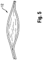
- the balloon may also be subject to a phenomenon known as "pancaking." In this condition, the balloon 12 folds down upon itself to a flattened state, as shown in Figure 5 . This situation may cause the balloon to be viewed through fluoroscopy as perhaps still being in the inflated condition, since the full width of the balloon may still be perceived. This can give the clinician the false perception that the balloon remains inflated, when in fact it is not.
- the need is identified for a balloon for which the working surface may be identified during an interventional procedure with enhanced precision.
- the solution would take into account the possible mismatch between fixed locations on the catheter shaft and the balloon to define the working surface.
- the improved identification may also allow for the better detection of the false perception of deflation caused by pancaking.
- procedural efficiency would be enhanced without remarkably increasing cost or complexity, and in a manner that can be applied to many existing catheter technologies without extensive modification.
- WO 2010/003135 A2 discloses an apparatus that is operable in different modes to perform various functions for treating a body lumen.
- An object of the disclosure is to provide a hub for a balloon for which the working surface may be identified during an interventional procedure with enhanced precision, as further disclosed in claim 1.
- a catheter 10 having a distal portion 11 with a balloon 12 mounted on a catheter tube 14.
- the balloon 12 has an intermediate section 16, or "barrel,” and end sections 18, 20.
- the end sections 18, 20 reduce in diameter to join the intermediate section 16 to the catheter tube 14 (and thus sections 18, 20 are generally termed cones or cone sections).
- the balloon 12 is sealed at balloon ends (proximal end 15a and distal end 15b) on the cone sections 18,20 to allow the inflation of the balloon 12 via one or more inflation lumens 17 extending within catheter tube 14 and communicating with the interior of the balloon 12.
- the catheter tube 14 also includes an elongated, tubular shaft 24 forming a guidewire lumen 23 that directs the guidewire 26 through the catheter 10, and along the distal end of which the balloon 12 may be located.
- this guidewire 26 may extend through the proximal end of the catheter 10 and a first port 25 of a connector 27 into the lumen 23 to achieve an "over the wire” (OTW) arrangement, but could also be provided in a "rapid exchange” (RX) configuration, in which the guidewire 26 exits a lateral opening 14a closer to the distal end (see Figure 9 ) or else is fed through the tip distally of the balloon 12 (not shown).
- a second port 29 may also be associated with catheter 10, such as by way of connector 27, for introducing a fluid (e.g., saline, a contrast agent, or both) into the interior compartment of the balloon 12 via the inflation lumen 17.
- a fluid e.g., saline, a contrast agent, or both
- Balloon 12 may include a single or multi-layered balloon wall 28 forming the interior for receiving the inflation fluid.
- the balloon 12 may be a non-compliant balloon having a balloon wall 28 that maintains its size and shape in one or more directions when the balloon is inflated. Examples of non-compliant balloons may be found in U.S. Pat. No. 6,746,425 and Publication Nos. US 2006/0085022 , US 2006/0085023 and US 2006/0085024 .
- the balloon 12 in such case also has a pre-determined surface area that remains constant during and after inflation, also has a pre-determined length and pre-determined diameter that each, or together, remain constant during and after inflation.
- the balloon 12 could be semi-compliant or compliant instead, depending on the particular use.
- the catheter 100 includes a seal 102, such as may be provided by one or more O-rings or the like, at or near a proximal end of the inner shaft 24.
- the seal 102 is adapted for positioning in a recess 104 formed in a receiver 101 for receiving the shaft 24, such as hub 106, which is shown as being oversized for purposes of illustration.
- the recess 104 is oversized so as to allow movement of the seal 102 and thus shaft 24 relative to the tube 14 within inflation lumen 17, which is in turn connected to the proximal end of the balloon 12.
- the shaft 24 is not connected to any other structure in the catheter 10, and thus can move to and from a distance in the longitudinal direction corresponding to the length of the recess 104.
- the balloon 12 may include a radiopaque identifier separate from the shaft 24 to allow for identification of a particular location under fluoroscopy.
- this identifier is provided in the form of an insert 44.
- This insert 44 may be tubular in form, and extend in a spaced apart manner along and generally coaxially with the shaft 24 extending through the interior compartment of the balloon 12, thus forming a sleeve.
- a free end portion 44a of the insert 44 is located at a position aligned with the edge or extent of the working surface W at the proximal end 15a, while the opposite, fixed end portion 44b is connected to the balloon 12, such as at the point where it attaches to the tube 14 at this proximal end.
- connection between the insert 44 and the balloon 12, tube 14, or both may be one or more of an interference fit, bonding (using an adhesive, welding, etc.), friction, or other like manners of forming a secure arrangement that does not permit relative movement of two distinct parts when connected.
- the insert 44 may also be adapted so as to minimize interference with the inflation of the balloon 12.
- the insert 44 may be provided with one or more perforations 45. These perforations 45 prevent the insert 44 from serving as a barrier that would retard the inflation fluid emanating from the tube 14 from readily flowing into the interior compartment of the balloon 12, and thus help to preserve the desired short inflation times. Indeed, the presence of such perforations 45 may allow the inserts 44 and 46 to be combined into a single unitary piece of material extending continuously between the proximal and distal ends 15a, 15b of the balloon 12.
- a second, at least partially radiopaque insert 46 may also be provided at the distal end 15b including the conical section 20.
- this insert 46 is arranged at the location where the distal end 15b of the balloon 12 is secured to the shaft 24 to form the tip P (which as noted may also be radiopaque).
- this insert 46 may be connected to the shaft 24, or may be embedded within the material forming the corresponding distal end 15b of the balloon 12 (especially if a multi-layered arrangement is used to form the balloon wall 28).
- the proximal end portion 46a of the insert 46 terminates at the distal edge of the working surface W, so as to assist in the identification process.
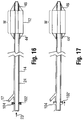
- the proximal end portion 46a of this insert 46 extending within the interior compartment of the balloon 12 may be spaced from the shaft 24 (note gap 47 in Figure 15 ) so as to be less susceptible to any misalignment caused by bending.
- This end 46a may be partially or entirely radiopaque. This radiopaque end portion 46a provides an indication of the distance between the distal edge of the working surface W and the distal end 15b of the balloon 12.
- distal end portion 46b of the insert 46 may be formed with the tip P as a unitary, continuously radiopaque structure (for example, with different radiopaque qualities (patterns, shapes, densities, etc.)), if desired to allow for ready identification of these components.
- the seal 102 provides the desired closed lumen 17 to receive the inflation fluid.
- the balloon 12 On inflation of the balloon 12, such as in a vessel V, any tendency of the shaft 24 to bend and cause misalignment has no impact on the location of the radiopaque identifier, such as inserts 44, 46.
- the insert 44 at the proximal end 15a is separate from the shaft 24, and the insert 46 at the distal end 15b of the balloon 12 may move along with the shaft 24, which is free to move in the longitudinal direction until the seal 102 reaches the distal end of the recess 104 (note position 102' in Figure 17 ).
- Balloons 12 that carry one or more surface elements, such as a payload (drug, stent, or both) or a working implement (cutter, focused force wire, or the like) into the vasculature may also benefit from the foregoing description of marking techniques.
- a balloon 12 including a defined working surface W may include a portion coated with such a drug D, such as one designed for achieving a desired therapeutic effect when applied to the interior of the vessel.
- the drug D may be applied to the inflated balloon as part of the manufacturing process, and prior to folding for insertion in the vasculature.
- the clinician may thus with the benefit of a fluoroscope determine the precise positioning of the working surface W prior to inflating the balloon 12 in the vasculature to deliver the drug D to the desired location and provide the desired treatment regimen.
Landscapes
- Health & Medical Sciences (AREA)
- Life Sciences & Earth Sciences (AREA)
- Heart & Thoracic Surgery (AREA)
- Biomedical Technology (AREA)
- Biophysics (AREA)
- Pulmonology (AREA)
- Engineering & Computer Science (AREA)
- Anesthesiology (AREA)
- Hematology (AREA)
- Animal Behavior & Ethology (AREA)
- General Health & Medical Sciences (AREA)
- Public Health (AREA)
- Veterinary Medicine (AREA)
- Child & Adolescent Psychology (AREA)
- Vascular Medicine (AREA)
- Media Introduction/Drainage Providing Device (AREA)
Description
- This disclosure relates generally to catheters for performing medical procedures, such as balloon angioplasty and, more particularly, to a catheter including a floating hub, which may be used for ensuring the proper alignment between a radiopaque identifier and a portion of the balloon, such as the working surface.
- Balloons are routinely used to resolve or address flow restrictions or perhaps even complete blockages in tubular areas of the body, such as arteries or veins. In many clinical situations, the restrictions are caused by hard solids, such as calcified plaque, and require the use of high pressures to compact such blockages. Commercially available balloons employ complex technology to achieve high pressure requirements without sacrificing the profile of the balloon. Besides high pressure requirements, the balloons should also be resistant to puncture, easy to track and push, and present a low profile, especially when used for angioplasty.
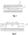
- In clinical practice, angioplasty balloons are expanded from a deflated, folded state to an expanded state within a vessel to treat a target area, such as a portion of the circumferential inner wall I of a blood vessel V, as shown in
Figures 1 and 2 . The inflation of aballoon 12 withwall 28 is traditionally completed using an X-ray contrast agent CM along dimension DX to provide better visibility under X-ray or other form of radiography R during the interventional procedure, as illustrated inFigures 3 and 3a (which shows the intensity measured by a fluoroscope detector plate, FDP). Typically, a 70/30 percent mixture of contrast agent and saline is used to inflate the balloon during an angioplasty procedure. - In general, a desirable goal is to reduce inflation and deflation times required for balloons without sacrificing the profile of the balloons, especially for large volume balloons (which can require up to two minutes of inflation/deflation times with the contrast agent). Because of its relatively high viscosity, it would also be desirable to eliminate, or at least reduce the amount of, the contrast agent used in inflation/deflation of the balloons. The use of contrast agent prolongs the inflation/deflation times and also poses the risk of iodine exposure to patients sensitive to iodine. In this regard, a non-radiopaque substance could be used in lieu of the contrast agent, such as for example saline or carbon dioxide, but such substances are invisible during X- ray imaging, and thus do not enhance visibility.
- Furthermore, the physician performing the angioplasty procedure should be able to locate the position of the uninflated balloon with accuracy, so that the balloon will be properly positioned once inflated. This is conventionally accomplished by attaching marker bands on the catheter shaft in the region corresponding to the balloon working surface. This "working surface" is the surface along the portion of the balloon that is used to achieve the desired treatment effect, such as contacting the calcified plaque (which surface in the case of a balloon having conical or tapering sections at the proximal and distal ends is typically co-extensive with a generally cylindrical barrel section).
- Misalignment of the marker bands during placement along the shaft sometimes results in their failure to correspond precisely to the extent of the working surface, as is shown in
Figure 4 (note misalignment amount X between each interior marker band M carried by shaft S and working surface W ofballoon 12, which also typically includes a radiopaque tip P at the distal end). Even upon exercising great care to position the markers properly on the underlying shaft in alignment with anticipated boundaries of the working surface when the balloon is inflated, there remains a tendency for mismatch due to several possible factors. One such factor may be the tolerance stack-ups arising as a consequence of the affixation of the balloon to the distal end of the catheter shaft. The balloon also has a tendency to grow in the longitudinal direction when inflated, especially with large and particularly long balloons. Another factor is the tendency of the portion of the catheter shaft within the balloon to bend or flex during inflation. This may lead to misalignment between radiopaque markers fixed to the shaft and the working surface. - Whatever the cause, the resulting misalignment may prevent the clinician from accurately identifying the location of the working surface of the balloon during an interventional procedure. This may lead to a geographic misplacement, or "miss," of the intended contact between the target area T and the working surface W of the balloon 12 (see
Figure 2 ). It is especially desirable to avoid such an outcome when the balloon is designed to deliver a payload (such as a drug, stent, or both) or a working element to a specified location within the vasculature, since a miss may prolong the procedure (such as, for example, by requiring redeployment of theballoon 12 or the use of another balloon catheter in the case of a drug coated balloon). - Upon deflation, the balloon may also be subject to a phenomenon known as "pancaking." In this condition, the
balloon 12 folds down upon itself to a flattened state, as shown inFigure 5 . This situation may cause the balloon to be viewed through fluoroscopy as perhaps still being in the inflated condition, since the full width of the balloon may still be perceived. This can give the clinician the false perception that the balloon remains inflated, when in fact it is not. - Accordingly, the need is identified for a balloon for which the working surface may be identified during an interventional procedure with enhanced precision. The solution would take into account the possible mismatch between fixed locations on the catheter shaft and the balloon to define the working surface. The improved identification may also allow for the better detection of the false perception of deflation caused by pancaking. Overall, procedural efficiency would be enhanced without remarkably increasing cost or complexity, and in a manner that can be applied to many existing catheter technologies without extensive modification.
-
WO 2010/003135 A2 discloses an apparatus that is operable in different modes to perform various functions for treating a body lumen. - An object of the disclosure is to provide a hub for a balloon for which the working surface may be identified during an interventional procedure with enhanced precision, as further disclosed in claim 1.
-
-
Figures 1-9 are illustrative of the background of the disclosure; -
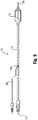
Figure 10 illustrates a first embodiment according to the disclosure; -
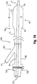
Figure 11 illustrates a second embodiment according to the disclosure; -
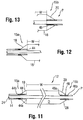
Figures 12 and 13 are partial views of theFigure 11 embodiment; -
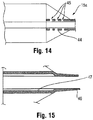
Figures 14 and 15 illustrate additional aspects of the disclosure; -
Figure 15 illustrates the embodiment ofFigure 14 in a folded condition; and -
Figures 16 and 17 illustrate a further embodiment according to the disclosure. - The description provided below and in regard to the figures applies to all embodiments unless noted otherwise, and features common to each embodiment are similarly shown and numbered.
- Provided is a
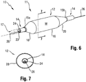
catheter 10 having adistal portion 11 with aballoon 12 mounted on acatheter tube 14. Referring toFigures 6, 7 , and8 , theballoon 12 has anintermediate section 16, or "barrel," andend sections end sections intermediate section 16 to the catheter tube 14 (and thussections balloon 12 is sealed at balloon ends (proximal end 15a anddistal end 15b) on thecone sections balloon 12 via one ormore inflation lumens 17 extending withincatheter tube 14 and communicating with the interior of theballoon 12. - The
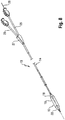
catheter tube 14 also includes an elongated,tubular shaft 24 forming aguidewire lumen 23 that directs theguidewire 26 through thecatheter 10, and along the distal end of which theballoon 12 may be located. As illustrated inFigure 8 , thisguidewire 26 may extend through the proximal end of thecatheter 10 and afirst port 25 of aconnector 27 into thelumen 23 to achieve an "over the wire" (OTW) arrangement, but could also be provided in a "rapid exchange" (RX) configuration, in which theguidewire 26 exits alateral opening 14a closer to the distal end (seeFigure 9 ) or else is fed through the tip distally of the balloon 12 (not shown). Asecond port 29 may also be associated withcatheter 10, such as by way ofconnector 27, for introducing a fluid (e.g., saline, a contrast agent, or both) into the interior compartment of theballoon 12 via theinflation lumen 17. -
Balloon 12 may include a single ormulti-layered balloon wall 28 forming the interior for receiving the inflation fluid. Theballoon 12 may be a non-compliant balloon having aballoon wall 28 that maintains its size and shape in one or more directions when the balloon is inflated. Examples of non-compliant balloons may be found inU.S. Pat. No. 6,746,425 and Publication Nos.US 2006/0085022 ,US 2006/0085023 andUS 2006/0085024 . Theballoon 12 in such case also has a pre-determined surface area that remains constant during and after inflation, also has a pre-determined length and pre-determined diameter that each, or together, remain constant during and after inflation. However, theballoon 12 could be semi-compliant or compliant instead, depending on the particular use. - One embodiment for achieving the desired features is by arranging the
shaft 24 in a manner that allows it to move a predetermined amount under a restrained condition in order to align the working surface W with particular location, such as the position of one or more radiopaque identifiers. In one embodiment, as shown schematically inFigure 10 , thecatheter 100 includes aseal 102, such as may be provided by one or more O-rings or the like, at or near a proximal end of theinner shaft 24. Theseal 102 is adapted for positioning in arecess 104 formed in areceiver 101 for receiving theshaft 24, such ashub 106, which is shown as being oversized for purposes of illustration. Therecess 104 is oversized so as to allow movement of theseal 102 and thusshaft 24 relative to thetube 14 withininflation lumen 17, which is in turn connected to the proximal end of theballoon 12. Other than at thedistal end 15b ofballoon 12 and theseal 102, theshaft 24 is not connected to any other structure in thecatheter 10, and thus can move to and from a distance in the longitudinal direction corresponding to the length of therecess 104. - Turning to
Figures 11-15 , theballoon 12 may include a radiopaque identifier separate from theshaft 24 to allow for identification of a particular location under fluoroscopy. In one embodiment, this identifier is provided in the form of aninsert 44. Thisinsert 44 may be tubular in form, and extend in a spaced apart manner along and generally coaxially with theshaft 24 extending through the interior compartment of theballoon 12, thus forming a sleeve. Afree end portion 44a of theinsert 44 is located at a position aligned with the edge or extent of the working surface W at theproximal end 15a, while the opposite, fixedend portion 44b is connected to theballoon 12, such as at the point where it attaches to thetube 14 at this proximal end. The connection between theinsert 44 and theballoon 12,tube 14, or both, may be one or more of an interference fit, bonding (using an adhesive, welding, etc.), friction, or other like manners of forming a secure arrangement that does not permit relative movement of two distinct parts when connected. - The
insert 44 may also be adapted so as to minimize interference with the inflation of theballoon 12. For example, as shown inFigure 14 , theinsert 44 may be provided with one ormore perforations 45. Theseperforations 45 prevent theinsert 44 from serving as a barrier that would retard the inflation fluid emanating from thetube 14 from readily flowing into the interior compartment of theballoon 12, and thus help to preserve the desired short inflation times. Indeed, the presence ofsuch perforations 45 may allow theinserts distal ends balloon 12. - A second, at least partially
radiopaque insert 46 may also be provided at thedistal end 15b including theconical section 20. In one embodiment, thisinsert 46 is arranged at the location where thedistal end 15b of theballoon 12 is secured to theshaft 24 to form the tip P (which as noted may also be radiopaque). As shown inFigure 15 , thisinsert 46 may be connected to theshaft 24, or may be embedded within the material forming the correspondingdistal end 15b of the balloon 12 (especially if a multi-layered arrangement is used to form the balloon wall 28). - Other types of identifiers may also be used instead of or in addition to the
particular inserts - In any case, the
proximal end portion 46a of theinsert 46 terminates at the distal edge of the working surface W, so as to assist in the identification process. Theproximal end portion 46a of thisinsert 46 extending within the interior compartment of theballoon 12 may be spaced from the shaft 24 (note gap 47 inFigure 15 ) so as to be less susceptible to any misalignment caused by bending. Thisend 46a may be partially or entirely radiopaque. Thisradiopaque end portion 46a provides an indication of the distance between the distal edge of the working surface W and thedistal end 15b of theballoon 12. Also, thedistal end portion 46b of theinsert 46 may be formed with the tip P as a unitary, continuously radiopaque structure (for example, with different radiopaque qualities (patterns, shapes, densities, etc.)), if desired to allow for ready identification of these components. - With reference now to
Figures 16 and 17 , it can be understood that theseal 102 provides the desired closed lumen 17 to receive the inflation fluid. On inflation of theballoon 12, such as in a vessel V, any tendency of theshaft 24 to bend and cause misalignment has no impact on the location of the radiopaque identifier, such asinserts insert 44 at theproximal end 15a is separate from theshaft 24, and theinsert 46 at thedistal end 15b of theballoon 12 may move along with theshaft 24, which is free to move in the longitudinal direction until theseal 102 reaches the distal end of the recess 104 (note position 102' inFigure 17 ). This tends to eliminate any tendency of theshaft 24 within theballoon 12 to bend, and even with minor bending, theinserts shaft 24 most susceptible to bending. The result is a more precise alignment of the radiopaque identifier with the target treatment area and ultimately with the working surface W of theballoon 12, and without regard to any bending of theshaft 24. -
Balloons 12 that carry one or more surface elements, such as a payload (drug, stent, or both) or a working implement (cutter, focused force wire, or the like) into the vasculature may also benefit from the foregoing description of marking techniques. For example, as shown inFigure 10 , aballoon 12 including a defined working surface W may include a portion coated with such a drug D, such as one designed for achieving a desired therapeutic effect when applied to the interior of the vessel. The drug D may be applied to the inflated balloon as part of the manufacturing process, and prior to folding for insertion in the vasculature. The clinician may thus with the benefit of a fluoroscope determine the precise positioning of the working surface W prior to inflating theballoon 12 in the vasculature to deliver the drug D to the desired location and provide the desired treatment regimen.
Claims (3)
- A hub (106) for a balloon catheter (10) having an elongated, tubular shaft (24) extending in a longitudinal direction, said shaft (24) having a proximal end and a distal end, and an inflatable balloon (12) connected to the distal end of the shaft for being inflated by an inflation fluid, comprising:a body including a receiver (101) for receiving a proximal portion of the shaft (24) and adapted for allowing the shaft (24) to move relative to the receiver in at least the longitudinal direction; anda stop (102) for restraining the movement of the shaft relative to the body in the longitudinal direction;the receiver comprising a recess (104) for receiving the stop, wherein the stop forms a seal (102) with the recess (104) of the receiver for receiving the stop to prevent the inflation fluid from passing,
characterised in that said recess (104) has a dimension in the longitudinal direction that is greater than a corresponding dimension of the stop (102). - The hub of claim 1, wherein the body includes a guidewire port (25) arranged in communication with the receiver, and further including an inflation port (29) for introducing the inflation fluid for inflating the balloon.
- The hub of claim 1 or 2, wherein the stop comprises an O-ring.
Applications Claiming Priority (4)
| Application Number | Priority Date | Filing Date | Title |
|---|---|---|---|
| US201261608927P | 2012-03-09 | 2012-03-09 | |
| NL2008453 | 2012-03-09 | ||
| PCT/US2013/029989 WO2013134702A1 (en) | 2012-03-09 | 2013-03-08 | Balloon catheter with floating hub |
| EP13721138.9A EP2822629B1 (en) | 2012-03-09 | 2013-03-08 | Balloon catheter with floating hub |
Related Parent Applications (1)
| Application Number | Title | Priority Date | Filing Date |
|---|---|---|---|
| EP13721138.9A Division EP2822629B1 (en) | 2012-03-09 | 2013-03-08 | Balloon catheter with floating hub |
Publications (2)
| Publication Number | Publication Date |
|---|---|
| EP3569279A1 EP3569279A1 (en) | 2019-11-20 |
| EP3569279B1 true EP3569279B1 (en) | 2020-12-30 |
Family
ID=49117406
Family Applications (2)
| Application Number | Title | Priority Date | Filing Date |
|---|---|---|---|
| EP19181644.6A Active EP3569279B1 (en) | 2012-03-09 | 2013-03-08 | Balloon catheter with floating hub |
| EP13721138.9A Active EP2822629B1 (en) | 2012-03-09 | 2013-03-08 | Balloon catheter with floating hub |
Family Applications After (1)
| Application Number | Title | Priority Date | Filing Date |
|---|---|---|---|
| EP13721138.9A Active EP2822629B1 (en) | 2012-03-09 | 2013-03-08 | Balloon catheter with floating hub |
Country Status (10)
| Country | Link |
|---|---|
| US (3) | US20150105722A1 (en) |
| EP (2) | EP3569279B1 (en) |
| JP (1) | JP6382112B2 (en) |
| KR (1) | KR20140133555A (en) |
| CN (1) | CN104245030B (en) |
| AU (1) | AU2013229831B2 (en) |
| CO (1) | CO7170134A2 (en) |
| IN (1) | IN2014DN07119A (en) |
| MX (2) | MX2014010837A (en) |
| WO (1) | WO2013134702A1 (en) |
Families Citing this family (10)
| Publication number | Priority date | Publication date | Assignee | Title |
|---|---|---|---|---|
| AU2013229820B2 (en) | 2012-03-09 | 2017-05-11 | Clearstream Technologies Limited | Medical balloon with radiopaque end portion for precisely identifying a working surface location |
| JP6223370B2 (en) | 2012-03-09 | 2017-11-01 | クリアストリーム・テクノロジーズ・リミテッド | Medical balloon having a radiopaque insert for accurately identifying the location of the working surface |
| JP6313230B2 (en) | 2012-03-09 | 2018-04-18 | クリアストリーム・テクノロジーズ・リミテッド | Parison, medical balloon, and related methods for forming a blow molded medical balloon with a modification |
| US10413703B2 (en) | 2012-12-31 | 2019-09-17 | Clearstream Technologies Limited | Catheter with markings to facilitate alignment |
| MA40946A (en) | 2014-11-14 | 2017-09-19 | Access Closure Inc | APPARATUS AND METHODS FOR MAKING A VASCULAR PUNCTURE WATERTIGHT |
| USD847988S1 (en) | 2015-11-13 | 2019-05-07 | Access Closure, Inc. | Handle grip |
| USD843573S1 (en) | 2015-11-13 | 2019-03-19 | Access Closure, Inc. | Vascular closure apparatus |
| USD865166S1 (en) | 2015-11-13 | 2019-10-29 | Access Closure, Inc. | Sheath adapter |
| WO2019065280A1 (en) * | 2017-09-27 | 2019-04-04 | テルモ株式会社 | Balloon catheter |
| WO2019180928A1 (en) * | 2018-03-23 | 2019-09-26 | 朝日インテック株式会社 | Balloon catheter |
Family Cites Families (32)
| Publication number | Priority date | Publication date | Assignee | Title |
|---|---|---|---|---|
| US4723947A (en) | 1986-04-09 | 1988-02-09 | Pacesetter Infusion, Ltd. | Insulin compatible infusion set |
| US4819751A (en) * | 1987-10-16 | 1989-04-11 | Baxter Travenol Laboratories, Inc. | Valvuloplasty catheter and method |
| US5085636A (en) * | 1989-01-13 | 1992-02-04 | Scimed Life Systems, Inc. | Balloon catheter with inflation-deflation valve |
| US5154093A (en) | 1990-06-08 | 1992-10-13 | Ford Motor Company | Adjustable cable end fitting |
| US5263962A (en) * | 1990-11-21 | 1993-11-23 | Johnson Medical Development Corp. | Balloon catheter and method of using the same |
| US5893840A (en) * | 1991-01-04 | 1999-04-13 | Medtronic, Inc. | Releasable microcapsules on balloon catheters |
| US5514093A (en) * | 1994-05-19 | 1996-05-07 | Scimed Life Systems, Inc. | Variable length balloon dilatation catheter |
| JPH0852218A (en) * | 1994-08-10 | 1996-02-27 | Nippon Zeon Co Ltd | Sliding catheter |
| US5536252A (en) * | 1994-10-28 | 1996-07-16 | Intelliwire, Inc. | Angioplasty catheter with multiple coaxial balloons |
| US6059752A (en) * | 1994-12-09 | 2000-05-09 | Segal; Jerome | Mechanical apparatus and method for dilating and irradiating a site of treatment |
| US5932307A (en) | 1996-05-03 | 1999-08-03 | Baxter International Inc. | Oriented medical tubing |
| US6746425B1 (en) | 1996-06-14 | 2004-06-08 | Futuremed Interventional | Medical balloon |
| US5779731A (en) * | 1996-12-20 | 1998-07-14 | Cordis Corporation | Balloon catheter having dual markers and method |
| US6520934B1 (en) * | 1999-12-29 | 2003-02-18 | Advanced Cardiovascular Systems, Inc. | Catheter assemblies with flexible radiopaque marker |
| US6544222B1 (en) * | 2000-11-14 | 2003-04-08 | Advanced Cardiovascular Systems, Inc. | Visualization through an opaque medical device component |
| US7322958B2 (en) * | 2001-12-27 | 2008-01-29 | Wholey Mark H | Apparatus for thromboembolic protection |
| DE202004000533U1 (en) | 2004-01-15 | 2004-03-18 | Rehau Ag + Co. | Armored polymer hose and device for manufacturing |
| US7682335B2 (en) | 2004-10-15 | 2010-03-23 | Futurematrix Interventional, Inc. | Non-compliant medical balloon having an integral non-woven fabric layer |
| US7309324B2 (en) | 2004-10-15 | 2007-12-18 | Futuremed Interventional, Inc. | Non-compliant medical balloon having an integral woven fabric layer |
| US7354419B2 (en) | 2004-10-15 | 2008-04-08 | Futuremed Interventional, Inc. | Medical balloon having strengthening rods |
| US20080228138A1 (en) * | 2005-03-31 | 2008-09-18 | Van Sloten Leonard A | Catheter with balloon having visual marker |
| US7195612B2 (en) * | 2005-03-31 | 2007-03-27 | Gordis Corporation | Esophageal balloon catheter with visual marker |
| US20070100280A1 (en) * | 2005-03-31 | 2007-05-03 | Van Sloten Leonard A | Catheter with balloon material having visual marker |
| US9352133B2 (en) * | 2005-06-09 | 2016-05-31 | Boston Scientific Scimed, Inc. | Balloon catheters with increased column strength |
| US8556851B2 (en) * | 2005-07-05 | 2013-10-15 | Angioslide Ltd. | Balloon catheter |
| JP2009509622A (en) * | 2005-10-03 | 2009-03-12 | ワイ メッド インク | Vascular treatment device |
| US8197505B2 (en) * | 2005-10-14 | 2012-06-12 | Endocross Ltd. | Balloon catheter system for treating vascular occlusions |
| US7896840B2 (en) * | 2007-04-05 | 2011-03-01 | Boston Scientific Scimed, Inc. | Catheter having internal mechanisms to encourage balloon re-folding |
| EP2173408A1 (en) | 2007-06-27 | 2010-04-14 | Medingo Ltd. | Tubing for fluid delivery device |
| US9682526B2 (en) | 2007-10-02 | 2017-06-20 | Meissner Filtration Products, Inc. | Radio frequency weldable multilayer tubing and method of making the same |
| US8420110B2 (en) * | 2008-03-31 | 2013-04-16 | Cordis Corporation | Drug coated expandable devices |
| EP2902070B1 (en) * | 2008-07-03 | 2016-10-05 | Hotspur Technologies, Inc | Apparatus for treating obstructions within body lumens |
-
2013
- 2013-03-08 US US14/383,774 patent/US20150105722A1/en not_active Abandoned
- 2013-03-08 JP JP2014561162A patent/JP6382112B2/en active Active
- 2013-03-08 MX MX2014010837A patent/MX2014010837A/en active IP Right Grant
- 2013-03-08 CN CN201380020463.8A patent/CN104245030B/en active Active
- 2013-03-08 MX MX2020009591A patent/MX2020009591A/en unknown
- 2013-03-08 EP EP19181644.6A patent/EP3569279B1/en active Active
- 2013-03-08 IN IN7119DEN2014 patent/IN2014DN07119A/en unknown
- 2013-03-08 KR KR1020147025019A patent/KR20140133555A/en not_active Application Discontinuation
- 2013-03-08 WO PCT/US2013/029989 patent/WO2013134702A1/en active Application Filing
- 2013-03-08 AU AU2013229831A patent/AU2013229831B2/en active Active
- 2013-03-08 EP EP13721138.9A patent/EP2822629B1/en active Active
-
2014
- 2014-09-16 CO CO14205043A patent/CO7170134A2/en unknown
-
2018
- 2018-09-17 US US16/133,251 patent/US10994096B2/en active Active
-
2021
- 2021-04-28 US US17/242,726 patent/US11878134B2/en active Active
Non-Patent Citations (1)
| Title |
|---|
| None * |
Also Published As
| Publication number | Publication date |
|---|---|
| JP6382112B2 (en) | 2018-08-29 |
| MX2020009591A (en) | 2022-08-02 |
| IN2014DN07119A (en) | 2015-04-24 |
| US20190083744A1 (en) | 2019-03-21 |
| US20210316114A1 (en) | 2021-10-14 |
| EP2822629A1 (en) | 2015-01-14 |
| AU2013229831B2 (en) | 2017-10-26 |
| CN104245030B (en) | 2018-03-02 |
| US20150105722A1 (en) | 2015-04-16 |
| MX2014010837A (en) | 2015-06-03 |
| US10994096B2 (en) | 2021-05-04 |
| JP2015512696A (en) | 2015-04-30 |
| US11878134B2 (en) | 2024-01-23 |
| CO7170134A2 (en) | 2015-01-28 |
| EP2822629B1 (en) | 2019-07-03 |
| WO2013134702A1 (en) | 2013-09-12 |
| WO2013134702A4 (en) | 2013-10-10 |
| CN104245030A (en) | 2014-12-24 |
| KR20140133555A (en) | 2014-11-19 |
| EP3569279A1 (en) | 2019-11-20 |
| AU2013229831A1 (en) | 2014-09-25 |
Similar Documents
| Publication | Publication Date | Title |
|---|---|---|
| EP3569279B1 (en) | Balloon catheter with floating hub | |
| EP2822628B1 (en) | Balloon catheter with expandable shaft | |
| EP2822632B1 (en) | Medical balloon including radiopaque insert for precisely identifying a working surface location | |
| JP6235011B2 (en) | Balloon catheter with improved positioning performance | |
| AU2019203245B2 (en) | Balloon catheter with adjustable inner member | |
| EP3524312B1 (en) | Medical balloon with radiopaque end portion for precisely identifying a working surface location | |
| EP2822635B1 (en) | Medical balloon with radiopaque identifier for precisely identifying the working surface | |
| EP3398644B1 (en) | Medical balloon including a radiopaque wire for precisely identifying a working surface location | |
| EP2822637B1 (en) | Medical balloon with multi-position actuator for precisely arranging the working surface |
Legal Events
| Date | Code | Title | Description |
|---|---|---|---|
| PUAI | Public reference made under article 153(3) epc to a published international application that has entered the european phase |
Free format text: ORIGINAL CODE: 0009012 |
|
| STAA | Information on the status of an ep patent application or granted ep patent |
Free format text: STATUS: THE APPLICATION HAS BEEN PUBLISHED |
|
| AC | Divisional application: reference to earlier application |
Ref document number: 2822629 Country of ref document: EP Kind code of ref document: P |
|
| AK | Designated contracting states |
Kind code of ref document: A1 Designated state(s): AL AT BE BG CH CY CZ DE DK EE ES FI FR GB GR HR HU IE IS IT LI LT LU LV MC MK MT NL NO PL PT RO RS SE SI SK SM TR |
|
| STAA | Information on the status of an ep patent application or granted ep patent |
Free format text: STATUS: REQUEST FOR EXAMINATION WAS MADE |
|
| 17P | Request for examination filed |
Effective date: 20200422 |
|
| RBV | Designated contracting states (corrected) |
Designated state(s): AL AT BE BG CH CY CZ DE DK EE ES FI FR GB GR HR HU IE IS IT LI LT LU LV MC MK MT NL NO PL PT RO RS SE SI SK SM TR |
|
| GRAP | Despatch of communication of intention to grant a patent |
Free format text: ORIGINAL CODE: EPIDOSNIGR1 |
|
| STAA | Information on the status of an ep patent application or granted ep patent |
Free format text: STATUS: GRANT OF PATENT IS INTENDED |
|
| INTG | Intention to grant announced |
Effective date: 20200811 |
|
| GRAS | Grant fee paid |
Free format text: ORIGINAL CODE: EPIDOSNIGR3 |
|
| GRAA | (expected) grant |
Free format text: ORIGINAL CODE: 0009210 |
|
| STAA | Information on the status of an ep patent application or granted ep patent |
Free format text: STATUS: THE PATENT HAS BEEN GRANTED |
|
| AC | Divisional application: reference to earlier application |
Ref document number: 2822629 Country of ref document: EP Kind code of ref document: P |
|
| AK | Designated contracting states |
Kind code of ref document: B1 Designated state(s): AL AT BE BG CH CY CZ DE DK EE ES FI FR GB GR HR HU IE IS IT LI LT LU LV MC MK MT NL NO PL PT RO RS SE SI SK SM TR |
|
| REG | Reference to a national code |
Ref country code: GB Ref legal event code: FG4D |
|
| REG | Reference to a national code |
Ref country code: AT Ref legal event code: REF Ref document number: 1349336 Country of ref document: AT Kind code of ref document: T Effective date: 20210115 |
|
| REG | Reference to a national code |
Ref country code: DE Ref legal event code: R096 Ref document number: 602013075107 Country of ref document: DE |
|
| REG | Reference to a national code |
Ref country code: IE Ref legal event code: FG4D |
|
| PG25 | Lapsed in a contracting state [announced via postgrant information from national office to epo] |
Ref country code: FI Free format text: LAPSE BECAUSE OF FAILURE TO SUBMIT A TRANSLATION OF THE DESCRIPTION OR TO PAY THE FEE WITHIN THE PRESCRIBED TIME-LIMIT Effective date: 20201230 Ref country code: RS Free format text: LAPSE BECAUSE OF FAILURE TO SUBMIT A TRANSLATION OF THE DESCRIPTION OR TO PAY THE FEE WITHIN THE PRESCRIBED TIME-LIMIT Effective date: 20201230 Ref country code: GR Free format text: LAPSE BECAUSE OF FAILURE TO SUBMIT A TRANSLATION OF THE DESCRIPTION OR TO PAY THE FEE WITHIN THE PRESCRIBED TIME-LIMIT Effective date: 20210331 Ref country code: NO Free format text: LAPSE BECAUSE OF FAILURE TO SUBMIT A TRANSLATION OF THE DESCRIPTION OR TO PAY THE FEE WITHIN THE PRESCRIBED TIME-LIMIT Effective date: 20210330 |
|
| REG | Reference to a national code |
Ref country code: AT Ref legal event code: MK05 Ref document number: 1349336 Country of ref document: AT Kind code of ref document: T Effective date: 20201230 |
|
| PG25 | Lapsed in a contracting state [announced via postgrant information from national office to epo] |
Ref country code: BG Free format text: LAPSE BECAUSE OF FAILURE TO SUBMIT A TRANSLATION OF THE DESCRIPTION OR TO PAY THE FEE WITHIN THE PRESCRIBED TIME-LIMIT Effective date: 20210330 Ref country code: SE Free format text: LAPSE BECAUSE OF FAILURE TO SUBMIT A TRANSLATION OF THE DESCRIPTION OR TO PAY THE FEE WITHIN THE PRESCRIBED TIME-LIMIT Effective date: 20201230 Ref country code: LV Free format text: LAPSE BECAUSE OF FAILURE TO SUBMIT A TRANSLATION OF THE DESCRIPTION OR TO PAY THE FEE WITHIN THE PRESCRIBED TIME-LIMIT Effective date: 20201230 |
|
| REG | Reference to a national code |
Ref country code: NL Ref legal event code: MP Effective date: 20201230 |
|
| PG25 | Lapsed in a contracting state [announced via postgrant information from national office to epo] |
Ref country code: HR Free format text: LAPSE BECAUSE OF FAILURE TO SUBMIT A TRANSLATION OF THE DESCRIPTION OR TO PAY THE FEE WITHIN THE PRESCRIBED TIME-LIMIT Effective date: 20201230 |
|
| REG | Reference to a national code |
Ref country code: LT Ref legal event code: MG9D |
|
| PG25 | Lapsed in a contracting state [announced via postgrant information from national office to epo] |
Ref country code: RO Free format text: LAPSE BECAUSE OF FAILURE TO SUBMIT A TRANSLATION OF THE DESCRIPTION OR TO PAY THE FEE WITHIN THE PRESCRIBED TIME-LIMIT Effective date: 20201230 Ref country code: PT Free format text: LAPSE BECAUSE OF FAILURE TO SUBMIT A TRANSLATION OF THE DESCRIPTION OR TO PAY THE FEE WITHIN THE PRESCRIBED TIME-LIMIT Effective date: 20210430 Ref country code: LT Free format text: LAPSE BECAUSE OF FAILURE TO SUBMIT A TRANSLATION OF THE DESCRIPTION OR TO PAY THE FEE WITHIN THE PRESCRIBED TIME-LIMIT Effective date: 20201230 Ref country code: CZ Free format text: LAPSE BECAUSE OF FAILURE TO SUBMIT A TRANSLATION OF THE DESCRIPTION OR TO PAY THE FEE WITHIN THE PRESCRIBED TIME-LIMIT Effective date: 20201230 Ref country code: SK Free format text: LAPSE BECAUSE OF FAILURE TO SUBMIT A TRANSLATION OF THE DESCRIPTION OR TO PAY THE FEE WITHIN THE PRESCRIBED TIME-LIMIT Effective date: 20201230 Ref country code: EE Free format text: LAPSE BECAUSE OF FAILURE TO SUBMIT A TRANSLATION OF THE DESCRIPTION OR TO PAY THE FEE WITHIN THE PRESCRIBED TIME-LIMIT Effective date: 20201230 |
|
| PG25 | Lapsed in a contracting state [announced via postgrant information from national office to epo] |
Ref country code: PL Free format text: LAPSE BECAUSE OF FAILURE TO SUBMIT A TRANSLATION OF THE DESCRIPTION OR TO PAY THE FEE WITHIN THE PRESCRIBED TIME-LIMIT Effective date: 20201230 Ref country code: AT Free format text: LAPSE BECAUSE OF FAILURE TO SUBMIT A TRANSLATION OF THE DESCRIPTION OR TO PAY THE FEE WITHIN THE PRESCRIBED TIME-LIMIT Effective date: 20201230 |
|
| PG25 | Lapsed in a contracting state [announced via postgrant information from national office to epo] |
Ref country code: IS Free format text: LAPSE BECAUSE OF FAILURE TO SUBMIT A TRANSLATION OF THE DESCRIPTION OR TO PAY THE FEE WITHIN THE PRESCRIBED TIME-LIMIT Effective date: 20210430 |
|
| REG | Reference to a national code |
Ref country code: DE Ref legal event code: R097 Ref document number: 602013075107 Country of ref document: DE |
|
| PG25 | Lapsed in a contracting state [announced via postgrant information from national office to epo] |
Ref country code: AL Free format text: LAPSE BECAUSE OF FAILURE TO SUBMIT A TRANSLATION OF THE DESCRIPTION OR TO PAY THE FEE WITHIN THE PRESCRIBED TIME-LIMIT Effective date: 20201230 Ref country code: IT Free format text: LAPSE BECAUSE OF FAILURE TO SUBMIT A TRANSLATION OF THE DESCRIPTION OR TO PAY THE FEE WITHIN THE PRESCRIBED TIME-LIMIT Effective date: 20201230 Ref country code: MC Free format text: LAPSE BECAUSE OF FAILURE TO SUBMIT A TRANSLATION OF THE DESCRIPTION OR TO PAY THE FEE WITHIN THE PRESCRIBED TIME-LIMIT Effective date: 20201230 |
|
| REG | Reference to a national code |
Ref country code: CH Ref legal event code: PL |
|
| PLBE | No opposition filed within time limit |
Free format text: ORIGINAL CODE: 0009261 |
|
| STAA | Information on the status of an ep patent application or granted ep patent |
Free format text: STATUS: NO OPPOSITION FILED WITHIN TIME LIMIT |
|
| PG25 | Lapsed in a contracting state [announced via postgrant information from national office to epo] |
Ref country code: DK Free format text: LAPSE BECAUSE OF FAILURE TO SUBMIT A TRANSLATION OF THE DESCRIPTION OR TO PAY THE FEE WITHIN THE PRESCRIBED TIME-LIMIT Effective date: 20201230 |
|
| 26N | No opposition filed |
Effective date: 20211001 |
|
| REG | Reference to a national code |
Ref country code: BE Ref legal event code: MM Effective date: 20210331 |
|
| PG25 | Lapsed in a contracting state [announced via postgrant information from national office to epo] |
Ref country code: ES Free format text: LAPSE BECAUSE OF FAILURE TO SUBMIT A TRANSLATION OF THE DESCRIPTION OR TO PAY THE FEE WITHIN THE PRESCRIBED TIME-LIMIT Effective date: 20201230 Ref country code: CH Free format text: LAPSE BECAUSE OF NON-PAYMENT OF DUE FEES Effective date: 20210331 Ref country code: LU Free format text: LAPSE BECAUSE OF NON-PAYMENT OF DUE FEES Effective date: 20210308 Ref country code: LI Free format text: LAPSE BECAUSE OF NON-PAYMENT OF DUE FEES Effective date: 20210331 |
|
| PG25 | Lapsed in a contracting state [announced via postgrant information from national office to epo] |
Ref country code: SI Free format text: LAPSE BECAUSE OF FAILURE TO SUBMIT A TRANSLATION OF THE DESCRIPTION OR TO PAY THE FEE WITHIN THE PRESCRIBED TIME-LIMIT Effective date: 20201230 |
|
| PG25 | Lapsed in a contracting state [announced via postgrant information from national office to epo] |
Ref country code: IS Free format text: LAPSE BECAUSE OF FAILURE TO SUBMIT A TRANSLATION OF THE DESCRIPTION OR TO PAY THE FEE WITHIN THE PRESCRIBED TIME-LIMIT Effective date: 20210430 |
|
| PG25 | Lapsed in a contracting state [announced via postgrant information from national office to epo] |
Ref country code: BE Free format text: LAPSE BECAUSE OF NON-PAYMENT OF DUE FEES Effective date: 20210331 |
|
| PG25 | Lapsed in a contracting state [announced via postgrant information from national office to epo] |
Ref country code: NL Free format text: LAPSE BECAUSE OF NON-PAYMENT OF DUE FEES Effective date: 20201230 Ref country code: CY Free format text: LAPSE BECAUSE OF FAILURE TO SUBMIT A TRANSLATION OF THE DESCRIPTION OR TO PAY THE FEE WITHIN THE PRESCRIBED TIME-LIMIT Effective date: 20201230 |
|
| PG25 | Lapsed in a contracting state [announced via postgrant information from national office to epo] |
Ref country code: SM Free format text: LAPSE BECAUSE OF FAILURE TO SUBMIT A TRANSLATION OF THE DESCRIPTION OR TO PAY THE FEE WITHIN THE PRESCRIBED TIME-LIMIT Effective date: 20201230 Ref country code: HU Free format text: LAPSE BECAUSE OF FAILURE TO SUBMIT A TRANSLATION OF THE DESCRIPTION OR TO PAY THE FEE WITHIN THE PRESCRIBED TIME-LIMIT; INVALID AB INITIO Effective date: 20130308 |
|
| PGFP | Annual fee paid to national office [announced via postgrant information from national office to epo] |
Ref country code: IE Payment date: 20240222 Year of fee payment: 12 |
|
| PG25 | Lapsed in a contracting state [announced via postgrant information from national office to epo] |
Ref country code: MK Free format text: LAPSE BECAUSE OF FAILURE TO SUBMIT A TRANSLATION OF THE DESCRIPTION OR TO PAY THE FEE WITHIN THE PRESCRIBED TIME-LIMIT Effective date: 20201230 |
|
| PGFP | Annual fee paid to national office [announced via postgrant information from national office to epo] |
Ref country code: DE Payment date: 20240220 Year of fee payment: 12 Ref country code: GB Payment date: 20240220 Year of fee payment: 12 |
|
| PGFP | Annual fee paid to national office [announced via postgrant information from national office to epo] |
Ref country code: FR Payment date: 20240221 Year of fee payment: 12 |
|
| PG25 | Lapsed in a contracting state [announced via postgrant information from national office to epo] |
Ref country code: MT Free format text: LAPSE BECAUSE OF FAILURE TO SUBMIT A TRANSLATION OF THE DESCRIPTION OR TO PAY THE FEE WITHIN THE PRESCRIBED TIME-LIMIT Effective date: 20201230 |