EP3569191B1 - Multifunctional visual electric toothbrush - Google Patents
Multifunctional visual electric toothbrush Download PDFInfo
- Publication number
- EP3569191B1 EP3569191B1 EP17891621.9A EP17891621A EP3569191B1 EP 3569191 B1 EP3569191 B1 EP 3569191B1 EP 17891621 A EP17891621 A EP 17891621A EP 3569191 B1 EP3569191 B1 EP 3569191B1
- Authority
- EP
- European Patent Office
- Prior art keywords
- electric toothbrush
- water
- main unit
- oral viewer
- head
- Prior art date
- Legal status (The legal status is an assumption and is not a legal conclusion. Google has not performed a legal analysis and makes no representation as to the accuracy of the status listed.)
- Active
Links
- 230000000007 visual effect Effects 0.000 title claims description 41
- XLYOFNOQVPJJNP-UHFFFAOYSA-N water Substances O XLYOFNOQVPJJNP-UHFFFAOYSA-N 0.000 claims description 141
- 238000004140 cleaning Methods 0.000 claims description 101
- 230000007246 mechanism Effects 0.000 claims description 61
- 241000628997 Flos Species 0.000 claims description 29
- 238000005507 spraying Methods 0.000 claims description 8
- 239000000725 suspension Substances 0.000 claims description 3
- 210000003128 head Anatomy 0.000 description 60
- 210000000214 mouth Anatomy 0.000 description 25
- 238000000034 method Methods 0.000 description 12
- 230000000694 effects Effects 0.000 description 10
- 238000005192 partition Methods 0.000 description 10
- 239000004973 liquid crystal related substance Substances 0.000 description 3
- 239000012530 fluid Substances 0.000 description 2
- 239000000126 substance Substances 0.000 description 2
- 206010006326 Breath odour Diseases 0.000 description 1
- 206010018275 Gingival atrophy Diseases 0.000 description 1
- 208000025157 Oral disease Diseases 0.000 description 1
- 208000014151 Stomatognathic disease Diseases 0.000 description 1
- 208000027418 Wounds and injury Diseases 0.000 description 1
- 230000000740 bleeding effect Effects 0.000 description 1
- 230000001680 brushing effect Effects 0.000 description 1
- 230000006378 damage Effects 0.000 description 1
- 239000006260 foam Substances 0.000 description 1
- 201000011560 gingival overgrowth Diseases 0.000 description 1
- 201000005562 gingival recession Diseases 0.000 description 1
- 238000005286 illumination Methods 0.000 description 1
- 208000014674 injury Diseases 0.000 description 1
- 238000003973 irrigation Methods 0.000 description 1
- 230000002262 irrigation Effects 0.000 description 1
- 239000007788 liquid Substances 0.000 description 1
- 239000000203 mixture Substances 0.000 description 1
- 208000030194 mouth disease Diseases 0.000 description 1
- 230000001575 pathological effect Effects 0.000 description 1
- 201000001245 periodontitis Diseases 0.000 description 1
- 239000010865 sewage Substances 0.000 description 1
- 210000004357 third molar Anatomy 0.000 description 1
- 229940034610 toothpaste Drugs 0.000 description 1
- 239000000606 toothpaste Substances 0.000 description 1
- 238000005406 washing Methods 0.000 description 1
Images


Classifications
-
- A—HUMAN NECESSITIES
- A61—MEDICAL OR VETERINARY SCIENCE; HYGIENE
- A61C—DENTISTRY; APPARATUS OR METHODS FOR ORAL OR DENTAL HYGIENE
- A61C17/00—Devices for cleaning, polishing, rinsing or drying teeth, teeth cavities or prostheses; Saliva removers; Dental appliances for receiving spittle
- A61C17/16—Power-driven cleaning or polishing devices
- A61C17/22—Power-driven cleaning or polishing devices with brushes, cushions, cups, or the like
- A61C17/32—Power-driven cleaning or polishing devices with brushes, cushions, cups, or the like reciprocating or oscillating
-
- A—HUMAN NECESSITIES
- A61—MEDICAL OR VETERINARY SCIENCE; HYGIENE
- A61C—DENTISTRY; APPARATUS OR METHODS FOR ORAL OR DENTAL HYGIENE
- A61C17/00—Devices for cleaning, polishing, rinsing or drying teeth, teeth cavities or prostheses; Saliva removers; Dental appliances for receiving spittle
- A61C17/16—Power-driven cleaning or polishing devices
- A61C17/22—Power-driven cleaning or polishing devices with brushes, cushions, cups, or the like
- A61C17/221—Control arrangements therefor
-
- A—HUMAN NECESSITIES
- A46—BRUSHWARE
- A46B—BRUSHES
- A46B15/00—Other brushes; Brushes with additional arrangements
- A46B15/0002—Arrangements for enhancing monitoring or controlling the brushing process
-
- A—HUMAN NECESSITIES
- A61—MEDICAL OR VETERINARY SCIENCE; HYGIENE
- A61C—DENTISTRY; APPARATUS OR METHODS FOR ORAL OR DENTAL HYGIENE
- A61C15/00—Devices for cleaning between the teeth
-
- A—HUMAN NECESSITIES
- A61—MEDICAL OR VETERINARY SCIENCE; HYGIENE
- A61C—DENTISTRY; APPARATUS OR METHODS FOR ORAL OR DENTAL HYGIENE
- A61C15/00—Devices for cleaning between the teeth
- A61C15/04—Dental floss; Floss holders
- A61C15/041—Dental floss
-
- A—HUMAN NECESSITIES
- A61—MEDICAL OR VETERINARY SCIENCE; HYGIENE
- A61C—DENTISTRY; APPARATUS OR METHODS FOR ORAL OR DENTAL HYGIENE
- A61C15/00—Devices for cleaning between the teeth
- A61C15/04—Dental floss; Floss holders
- A61C15/046—Flossing tools
- A61C15/047—Flossing tools power-driven
-
- A—HUMAN NECESSITIES
- A61—MEDICAL OR VETERINARY SCIENCE; HYGIENE
- A61C—DENTISTRY; APPARATUS OR METHODS FOR ORAL OR DENTAL HYGIENE
- A61C17/00—Devices for cleaning, polishing, rinsing or drying teeth, teeth cavities or prostheses; Saliva removers; Dental appliances for receiving spittle
- A61C17/06—Saliva removers; Accessories therefor
-
- A—HUMAN NECESSITIES
- A61—MEDICAL OR VETERINARY SCIENCE; HYGIENE
- A61C—DENTISTRY; APPARATUS OR METHODS FOR ORAL OR DENTAL HYGIENE
- A61C17/00—Devices for cleaning, polishing, rinsing or drying teeth, teeth cavities or prostheses; Saliva removers; Dental appliances for receiving spittle
- A61C17/16—Power-driven cleaning or polishing devices
- A61C17/22—Power-driven cleaning or polishing devices with brushes, cushions, cups, or the like
- A61C17/222—Brush body details, e.g. the shape thereof or connection to handle
-
- A—HUMAN NECESSITIES
- A61—MEDICAL OR VETERINARY SCIENCE; HYGIENE
- A61C—DENTISTRY; APPARATUS OR METHODS FOR ORAL OR DENTAL HYGIENE
- A61C17/00—Devices for cleaning, polishing, rinsing or drying teeth, teeth cavities or prostheses; Saliva removers; Dental appliances for receiving spittle
- A61C17/16—Power-driven cleaning or polishing devices
- A61C17/22—Power-driven cleaning or polishing devices with brushes, cushions, cups, or the like
- A61C17/225—Handles or details thereof
- A61C17/227—Handles or details thereof with reservoirs, e.g. for toothpaste
-
- A—HUMAN NECESSITIES
- A61—MEDICAL OR VETERINARY SCIENCE; HYGIENE
- A61C—DENTISTRY; APPARATUS OR METHODS FOR ORAL OR DENTAL HYGIENE
- A61C17/00—Devices for cleaning, polishing, rinsing or drying teeth, teeth cavities or prostheses; Saliva removers; Dental appliances for receiving spittle
- A61C17/16—Power-driven cleaning or polishing devices
- A61C17/22—Power-driven cleaning or polishing devices with brushes, cushions, cups, or the like
- A61C17/32—Power-driven cleaning or polishing devices with brushes, cushions, cups, or the like reciprocating or oscillating
- A61C17/34—Power-driven cleaning or polishing devices with brushes, cushions, cups, or the like reciprocating or oscillating driven by electric motor
- A61C17/3409—Power-driven cleaning or polishing devices with brushes, cushions, cups, or the like reciprocating or oscillating driven by electric motor characterized by the movement of the brush body
- A61C17/3481—Vibrating brush body, e.g. by using eccentric weights
-
- A—HUMAN NECESSITIES
- A46—BRUSHWARE
- A46B—BRUSHES
- A46B2200/00—Brushes characterized by their functions, uses or applications
- A46B2200/10—For human or animal care
- A46B2200/1066—Toothbrush for cleaning the teeth or dentures
-
- A—HUMAN NECESSITIES
- A61—MEDICAL OR VETERINARY SCIENCE; HYGIENE
- A61C—DENTISTRY; APPARATUS OR METHODS FOR ORAL OR DENTAL HYGIENE
- A61C2204/00—Features not otherwise provided for
Definitions
- the present disclosure relates to an oral cleaning tool, and more particularly to a multi-functional visual electric toothbrush for cleaning teeth, tooth gaps and an oral cavity.
- An electric toothbrush in the prior art has 30,000 vibrations or more per minute, which can cause a large amount of tiny bubbles in the mixture of toothpaste and water in an oral cavity, and attempts to use the pressure generated when the bubbles burst to achieve the purpose of cleaning dirt deep into tooth gaps. Even so, food debris embedded in the tooth gaps is still difficult to remove completely by means of the electric toothbrush in the prior art.
- US 2010/309302 A1 describes an apparatus and system for visualizing teeth cleaning, including an apparatus having a head with a removable cap having a tool configured for cleaning activities within a mouth.
- a handle is joined to the head for enabling the head to be manipulated within the mouth.
- An image sensor having a lens is at least partially disposed on the head for capturing images within the mouth.
- An illumination source is disposed on the head for illuminating objects to assist the image sensor in capturing the images.
- a transmitter conveys the images.
- a receiver receives the conveyed images.
- a display is connected to the receiver for displaying the conveyed images thereby assisting a user in the cleaning activities.
- US 2001/012605 A1 describes an oral cavity washer comprising: a video scope having image-forming means; an image pick-up device for converting the light from which the image is formed by the image-forming means into an electric signal; a first grip portion for being held by an operator; a display for displaying an image picked up by the video scope; an oral cavity washer having a nozzle for jetting a fluid; and a second grip portion for being held by the operator for washing an oral cavity by jetting the fluid to teeth or gums, wherein the first grip portion and the second grip portion are capable of being made integral with each other.
- WO 2013/001462 A2 describes a power operated electric toothbrush.
- the toothbrush includes: detachable bristles configured to be attached to a front portion of the toothbrush through a predefined locking mechanism to enable an oscillo-vibratory motion of the bristles; an intra-oral camera positioned above the detachable bristles to capture the images of the teeth; a first detachable configuration including the intra-oral camera and an illuminating means for mounting on to the toothbrush handle; and a second detachable configuration including the intra-oral camera, an illuminating means and the detachable bristles for mounting onto the toothbrush handle.
- the toothbrush further includes: an external water duct with a detachable locking mechanism for removing plaque and debris caught between the teeth utilizing an irrigation mechanism; and a conduit positioned at a rear portion of the bristle driving means including a momentary switch to perform a pressure sensing activity.
- the present invention provides a multi-functional visual electric toothbrush as set out in claim 1.
- a multi-functional visual electric toothbrush of the present disclosure not only has the large-area and high-efficiency cleaning ability of an electric toothbrush, but also can use a special tool such as an interdental brush, dental floss, a toothbrush, a water pick, an object fetching clamp and an object fetching hook to accurately perform targeted cleaning on difficult-to-clean parts such as tooth gaps under visual conditions.
- a special tool such as an interdental brush, dental floss, a toothbrush, a water pick, an object fetching clamp and an object fetching hook to accurately perform targeted cleaning on difficult-to-clean parts such as tooth gaps under visual conditions.
- the present disclosure provides a multi-functional visual electric toothbrush.
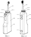
- the multi-functional visual electric toothbrush 900 is characterized by including a main unit 100, an oral viewer 200, an interdental cleaning appliance 400 and an electric toothbrush head 500.
- the main unit 100 includes a power system 11, a circuit system 12, a control system 13, a toothbrush driving mechanism 14 and a housing 15.
- the power system 11, the control system 13 and the toothbrush driving mechanism 14 are connected together through the circuit system 12.
- the electric toothbrush head 500 is connected to the toothbrush driving mechanism 14, and is mounted on the main unit 100.
- the oral viewer 200 includes a housing 21, a lighting system 23, an observation system 24 and a switch 26.
- the lighting system 23, the observation system 24, the power system 11 and the switch 26 are connected together through the circuit system 12 and the control system 13.
- the oral viewer 200 is connected to the main unit 100.
- the interdental cleaning appliance 400 is mounted on the oral viewer 200.
- the observation system 24 may be a camera system 24-1.
- the camera system 24-1 includes a camera 24-1-1, a data processing and output system 24-1-2 and a display 24-1-3. A picture shot by the camera 24-1-1 may be transmitted to the display 24-1-3 in time through the data processing and output system 24-1-2.
- the display 24-1-3 may be a smart phone 24-1-31, or a computer 24-1-32, or a liquid crystal display/television 24-1-33, or a tablet computer 24-1-34.
- the multi-functional visual electric toothbrush of the present disclosure integrates an electric toothbrush, an oral viewer and an interdental cleaning appliance effectively.
- the circuit system 12 and the control system 13 can not only connect the power system 11 to the toothbrush driving mechanism 14 to allow the toothbrush driving mechanism 14 to drive the electric toothbrush head 500 to work, but also connect the lighting system 23, the observation system 24 and the switch 26 of the oral viewer 200 to provide power required by working for the oral viewer 200, and control the oral viewer 200 to work.
- the main unit 100 can not only drive the electric toothbrush head 400, but also provide power and control systems for the lighting system 23, the observation system 24 and the like of the oral viewer 200, and transmit a picture shot by the camera 24-1-1 of the observation system 24 to the display 24-1-3, such as a smart phone 24-1-31, of the observation system 24 in time, so that the interdental cleaning process and cleaning effect of the interdental cleaning appliance 400 can be observed on a mobile phone immediately while cleaning, thereby achieving the purpose of thoroughly cleaning teeth and tooth gaps.
- toothbrush driving mechanism 14 arranged in the main unit 100 may be a motor-driven mechanically rotary toothbrush driving mechanism, and may also be an electrically-driven electromagnetic vibration driving mechanism.
- the toothbrush driving mechanism 14 generally adopts an electromagnetic vibration driving mechanism.
- the toothbrush driving mechanism 14 includes a vibration generating device 14-1 and a vibration transferring device 14-2 capable of transferring vibration generated by the vibration generating device 14-1.
- One end of the vibration transferring device 14-2 is connected to the vibration generating device 14-1, and the other end is connected to the electric toothbrush head 500.
- the vibration generating device 14-1 is an electromagnetic vibration device, which is an electromagnetic oscillator, or a magnetic suspension motor, or a piezoelectric transducer.
- the electric toothbrush head 500 is detachably mounted on the vibration transferring device 14-2. Usually, the electric toothbrush head 500 is detachably mounted at a distal end of the vibration transferring device 14-2.
- the detachable mounting manner may facilitate the detachment of the electric toothbrush head 500 from the main unit 100 for replacement, storage and carrying.
- the electric toothbrush head 500 may be detached from the main unit and replaced with the interdental cleaning appliance 400. It is more convenient for a user to use the interdental cleaning appliance 400 for further cleaning.
- the electric toothbrush head 500 is detachably mounted on the vibration transferring device 14-2 in a concave-convex engaging connection manner, an interference fit connection manner or a rotary connection manner.
- the applicant only enumerates the above three detachable connection manners.
- Persons skilled in the art may design different connection manners in conjunction with the prior art according to actual needs without departing from the scope of protection defined by the appended claims.
- the lighting system 23 and the observation system 24 are arranged at a front end 200-1 of the oral viewer 200, and the lighting system 23 and the observation system 24 are connected to the main unit 100 through the circuit system 12 and the control system 13. After the power system 11 is switched on, the switch 26 is turned on, and the main unit 100 can provide electric energy for the oral viewer 200 through the circuit system 12 and the control system 13, and drive the lighting system 23 and the observation system 24 of the oral viewer 200 to work.
- the front end 200-1 of the oral viewer 200 is detachably mounted on the main unit 100.
- the front end 200-1 of the oral viewer 200 is detachably mounted on the main unit 100.
- the front end 200-1 of the oral viewer 200 is detached from the main unit 100, the electric toothbrush head 500 is mounted on the vibration transferring device 14-2 of the toothbrush driving mechanism 14, and the main unit 100 drives the electric toothbrush head 500 to work through the toothbrush driving mechanism 14.
- the electric toothbrush head 500 is detached from the vibration transferring device 14-2, the front end 200-1 of the oral viewer 200 is mounted on the main unit 100, the oral cavity cleaning situation may be observed through the oral viewer 200, and the interdental cleaning appliance 400 is mounted on the oral viewer 200 for targeted cleaning as needed.
- the oral viewer 200, the interdental cleaning appliance 400 and the electric toothbrush head 500 may all be detached from the main unit, which facilitates separate storage and cleaning.
- the front end 200-1 of the oral viewer 200 is detachably mounted on the main unit 100 in a rotary connection manner or a concave-convex engaging connection manner.
- the applicant only enumerates the above two detachable connection manners.
- Persons skilled in the art may design different connection manners in conjunction with the prior art according to actual needs without departing from the scope of protection of the appended claims.
- the front end 200-1 of the oral viewer 200 is foldably mounted on the main unit 100.
- the front end 200-1 of the oral viewer 200 is foldably mounted on the main unit 100 through a rotation shaft type movement mechanism or a concave-convex engagement mechanism.
- the interdental cleaning appliance 400 is an interdental brush 401, or dental floss 402, or a toothbrush 403, or a water pick 404, or an object fetching clamp 405, or an object fetching hook 406.
- the applicant only enumerates the above six specific interdental cleaning appliances capable of being used cooperatively with the oral viewer 200. Persons skilled in the art may design other different cleaning appliances as needed to be used cooperatively with the oral viewer 200 for further cleaning the oral cavity, without departing from the scope of protection of the appended claims.
- a brush head 401-1 of the interdental brush 401, a line 402-1 of the dental floss 402, bristles 403-1 of the toothbrush 403, a water column sprayed by the water pick 404, a clamp head 405-1 of the object fetching clamp 405 and a head 406-1 of the object fetching hook 406 are within a visual field of the observation system 24 of the oral viewer 200, so that the observation system 24 can conveniently observe the cleaning situation of the interdental cleaning appliance 400 in real time.
- the interdental cleaning appliance 400 is detachably mounted on the oral viewer 200 through a connection mechanism 300.
- the cleaning appliance 400 is detachably mounted on the oral viewer 200. Therefore, the user may replace different interdental cleaning appliances 400 according to the needs of the use process, and the use process is more convenient.
- connection mechanism 300 is a rotary connection mechanism, or a concave-convex engaging connection mechanism, or an interference fit connection mechanism.
- connection mechanisms may also design connection mechanisms adopting different connection manners as needed without departing from the scope of protection of the appended claims.
- the water pick 404 includes a sprayer 404-1, a water tank 404-2, a water pipe 404-3, a water spraying switch 404-4 and a pressurizing device 404-5.
- the water tank 404-2 and the pressurizing device 404-5 are mounted on the housing 15 of the main unit 100.
- the sprayer 11 is mounted near the observation system 24 at the front end 200-1 of the oral viewer 200. Therefore, the water flow sprayed by the sprayer 11 may be maintained in the visual field of the observation system 24, so that the cleaning effect of the water pick 404 in the oral cavity is conveniently observed.
- the pressurizing device 404-5 is an electric pressurizing device 404-51.
- the electric pressurizing device 404-51 can realize automatic pressurizing only by turning on the power supply and keep the pressure stable, and the use process is more convenient.
- the electric pressurizing device 404-51 is an electric air pressurizing device 404-51-1 or an electric water pressurizing device 404-51-2.
- the electric pressurizing device 404-51 When the electric pressurizing device 404-51 is an electric air pressurizing device 404-51-1, the electric air pressurizing device 404-51-1 fills pressurized air into the water tank 404-2 and pressurizes water in the water tank 404-2, the water spraying switch 404-4 is turned on, and the pressurized water is sprayed out from the sprayer 404-1 through the water pipe 404-3 to rinse teeth or tooth gaps.
- the electric water pressurizing device 404-51-2 is a submersible pump 404-51-21 or a water pump 404-51-22.
- the electric water pressurizing device 404-51-2 is a submersible pump 404-51-21
- water in the water tank 404-2 is pumped into the submersible pump 404-51-21 for pressurizing, and the water pressurized by the submersible pump 404-51-21 is drained into the water pipe 404-3 and then sprayed out from the sprayer 404-1 to rinse teeth or tooth gaps.
- the electric water pressurizing device 404-51-2 is a water pump 404-51-22
- water in the water tank 404-2 is sucked into the water pump 404-51-22
- the water pressurized by the water pump 404-51-22 is drained into the water pipe 404-3 and then sprayed out from the sprayer 404-1 to rinse teeth or tooth gaps.
- the sprayer 404-1 of the water pick 404 may be disposed in the housing 21 at the front end 200-1 of the oral viewer 200.
- the water pick 404 may be used cooperatively with the interdental brush 401, or the dental floss 402, or the toothbrush 403, or the object fetching clamp 405, or the object fetching hook 406.
- the sprayer 404-1 of the water pick 404 is disposed in the housing 21 at the front end 200-1 of the oral viewer 200, so that other interdental cleaning appliances such as the interdental brush 401, or the dental floss 402, or the toothbrush 403, or the object fetching clamp 405, or the object fetching hook 406 may be conveniently mounted at the front end 200-1 of the oral viewer 200 through the connection mechanism 300 at the same time.
- the interdental brush 401, or the dental floss 402, or the toothbrush 403, or the object fetching clamp 405, or the object fetching hook 406 may be used for cleaning as needed while rinsing with water.
- the operation process may be transmitted to various displays in real time. Under the condition of direct vision, accurate targeted cleaning is performed on food debris or various foreign substances in the oral cavity are taken out, thereby greatly improving the cleaning effect. Moreover, the use process is safer and more convenient.
- the direction of a water column sprayed by the water pick 404 is substantially the same as the direction of the interdental brush 401 or the dental floss 402 entering tooth gaps.
- the water flow sprayed from the sprayer 404-1 can play a role in assisting in rinsing food debris at the tooth gaps.
- the electric toothbrush head 500 is first mounted on the toothbrush driving mechanism 14 of the main unit 100, and the electric toothbrush head 500 is used for cleaning the oral cavity over a large area.
- the electric toothbrush head 500 is then detached from the main unit 100, the oral viewer 200 is mounted on the main unit 100, and the cleaning situation in the oral cavity is observed through the oral viewer 200.
- the interdental cleaning appliance 400 such as the interdental brush 401, or the dental floss 402, or the toothbrush 403, or the water pick 404, or the object fetching clamp 405, or the object fetching hook 406 is mounted at the front end 200-1 of the oral viewer 200 according to the situations. Under the observation of the observation system 24 of the oral viewer 200, a part, such as a tooth gap, required for further targeted cleaning is further cleaned by using the interdental cleaning appliance 400.
- the multi-functional visual electric toothbrush of the present disclosure includes a main unit 100, an oral viewer 200, an interdental cleaning appliance 400 and an electric toothbrush head 500.
- the oral viewer 200 is connected to the main unit 100
- the interdental cleaning appliance 400 is connected to a front end 200-1 of the oral viewer 200
- the electric toothbrush head 500 is connected to a toothbrush driving mechanism 14 and is mounted on the main unit 100.
- a circuit system 12 and a control system 13 of the main unit 100 can not only transfer the energy of a power supply 11 to the toothbrush driving mechanism 14, so as to drive the electric toothbrush head 500 to work for large-area oral cleaning, but also connect a lighting system 23, an observation system 24 and a switch 26 of the oral viewer 200 to control the oral viewer 200 to work.
- the interdental cleaning appliance 400 may be used cooperatively with the oral viewer 200 to perform targeted cleaning on difficult-to-clean food debris in an oral cavity.
- a multi-functional visual electric toothbrush of the present disclosure not only has the large-area and high-efficiency cleaning ability of an electric toothbrush, but also can use a special tool such as an interdental brush, dental floss, a toothbrush, a water pick, an object fetching clamp and an object fetching hook to accurately perform targeted cleaning on difficult-to-clean parts such as tooth gaps under visual conditions.
- positioning block for mounting a water pick on the oral viewer 32. positioning slot for mounting a water pick on the oral viewer, 33. clamping block for mounting a water pick on the oral viewer.
- the multi-functional visual electric toothbrush of the present disclosure includes a main unit 100, an oral viewer 200, an interdental cleaning appliance 400 and an electric toothbrush head 500.
- the interdental cleaning appliance 400 includes a water pick 404.
- the main unit 100 includes a power system 11, a circuit system 12, a control system 13, a toothbrush driving mechanism 14 and a housing 15.
- a power switch 13-1 and a toothbrush driving switch 13-2 are arranged on the control system 13.
- the power switch 13-1 and the toothbrush driving switch 13-2 are arranged on the housing 15, referring to FIG. 1 and FIG. 1-1 .
- the toothbrush driving mechanism 14 adopts an electromagnetic vibration driving mechanism.
- the toothbrush driving mechanism 14 includes a vibration generating device 14-1 and a vibration transferring device 14-2 capable of transferring vibration generated by the vibration generating device 14-1.
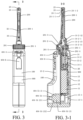
- a proximal end of the vibration transferring device 14-2 is connected to the vibration generating device 14-1, and a distal end is connected to the electric toothbrush head 500, referring to FIG. 2 and FIG. 2-1 .
- the vibration generating device 14-1 is an electromagnetic vibration device, which may be an electromagnetic oscillator, or a magnetic suspension motor, or a piezoelectric transducer, or electromagnetic vibration devices of other forms.
- an electromagnetic vibration device which may be an electromagnetic oscillator, or a magnetic suspension motor, or a piezoelectric transducer, or electromagnetic vibration devices of other forms.
- the applicant does not enumerate them one by one, but they do not depart from the scope of protection of the present application.
- toothbrush driving mechanism 14 arranged in the main unit 100 may also be a motor-driven mechanically rotary toothbrush driving mechanism, which will not be specifically described herein by the applicant.
- the housing 15 of the main unit 100 is internally provided with two portions: an electrical mounting space 15-1 and a water and waterway mounting space 15-2.
- the power system 11, the circuit system 12 and the control system 13 are mounted in the electrical mounting space 15-1, referring to FIG. 2-1 and FIG. 3-1 .
- the power system 11, the control system 13 and the toothbrush driving mechanism 14 are connected together through the circuit system 12.
- the power system 11 can drive the toothbrush driving mechanism to work, so as to drive the electric toothbrush head 500 to work.
- the oral viewer 200 includes a housing 21, a lighting system 23, an observation system 24 and a switch 26.
- the switch 26 is arranged on the housing 15 of the main unit 100.
- the lighting system 23 and the observation system 24 are arranged at a front end 200-1 of the oral viewer 200.
- the observation system 24 is a camera system 24-1.
- the camera system 24-1 includes a camera 24-1-1, a data processing and output system 24-1-2 and a display 24-1-3. A picture shot by the camera 24-1-1 may be transmitted to the display 24-1-3 in time through the data processing and output system 24-1-2.
- the display 24-1-3 may be a smart phone 24-1-31, or a computer 24-1-32, or a liquid crystal display/television 24-1-33, or a tablet computer 24-1-34, referring to FIG. 8 and FIG. 9 .
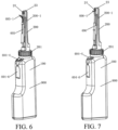
- the front end 200-1 of the oral viewer 200 is detachably connected to the main unit 100 in a threaded connection manner through a detachable threaded connection mechanism 201.
- the detachable threaded connection mechanism 201 includes a threaded upper cover 201-1, a waterway port 201-2, a circuit port 201-3 and a threaded base 201-4. Seal rings 201-5 are arranged at the waterway port 201-2 and the circuit port 201-3, so as to prevent sewage in a cleaning process from entering a circuit or a waterway, referring to FIG. 1-5 and FIG. 1-6 .
- the circuit system 12 and the control system 13 can also connect the lighting system 23, the observation system 24, the power system 11 and the switch 26 together, and the power system 11 can drive the lighting system 23 and the observation system 24 of the oral viewer 200 to work, so as to control the oral viewer 200 to work.
- the main unit 100 can not only drive the electric toothbrush head 500, but also provide power and control systems for the lighting system 23, the observation system 24 and the like of the oral viewer 200, and transmit a picture shot by the camera 24-1-1 of the observation system 24 to the display 24-1-3, such as a smart phone 24-1-31, of the observation system 24 in time, so that the interdental cleaning process and cleaning effect of the interdental cleaning appliance 400 can be observed on a mobile phone immediately while cleaning, thereby achieving the purpose of thoroughly cleaning teeth and tooth gaps.
- the electric toothbrush head 500 is detachably mounted at a distal end of the vibration transferring device 14-2.
- the detachable mounting manner may facilitate the detachment of the electric toothbrush head 500 from the main unit 100 for replacement, storage and carrying.
- the electric toothbrush head 500 may be detached from the main unit and replaced with the interdental cleaning appliance 400. It is more convenient for a user to use the interdental cleaning appliance 400 for further cleaning.
- the electric toothbrush head 500 is detachably mounted on the vibration transferring device 14-2 in a concave-convex engaging connection manner.
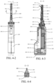
- the vibration transferring device 14-2 includes a transfer shaft connecting portion 14-2-1, and the transfer shaft connecting portion 14-2-1 is provided with a connection groove 14-2-11, a rotation stopping convex step 14-2-12 and a connection shaft 14-2-13.
- An elastic connection piece 51 and a mounting slot 52 are arranged at the bottom of the electric toothbrush head 500.
- the shape of the mounting slot 52 is matched with the outer contour of the transfer shaft connecting portion 14-2-1.
- the mounting slot 52 of the electric toothbrush head 500 is aligned with the transfer shaft connecting portion 14-2-1 and is pressed down slightly, the elastic connection piece 51 elastically deforms outward under the action of the connection shaft 14-2-13, the transfer shaft connecting portion 14-2-1 starts to enter the mounting slot 52 and continues to press down until reaching the connection groove 14-2-11, the external force of the elastic connection piece 51 is removed, and the elastic connection piece 51 restores to an original state and abuts against the interior of the connection groove 14-2-11, so that the electric toothbrush head 500 may be prevented from disengaging from the vibration transferring device 14-2.
- the electric toothbrush head 500 When the electric toothbrush head 500 is detached, the electric toothbrush head 500 may be pulled up forcefully, referring to FIG. 1-5 to FIG. 2-1 .
- the electric toothbrush head 500 may also be detachably mounted on the vibration transferring device 14-2 in other manners such as an interference fit connection manner or a rotary connection manner.
- the applicant will no longer enumerate one by one.
- the front end 200-1 of the oral viewer 200 is detached from the main unit 100, the electric toothbrush head 500 is mounted on the vibration transferring device 14-2 of the toothbrush driving mechanism 14, and the main unit 100 drives the electric toothbrush head 500 to work through the toothbrush driving mechanism 14.
- the electric toothbrush head 500 is detached from the vibration transferring device 14-2, the front end 200-1 of the oral viewer 200 is mounted on the main unit 100, the oral cavity cleaning situation may be observed through the oral viewer 200, and the interdental cleaning appliance 400 is mounted on the oral viewer 200 for targeted cleaning as needed.
- the oral viewer 200, the interdental cleaning appliance 400 and the electric toothbrush head 500 may all be detached from the main unit, which facilitates separate storage and cleaning.
- the interdental cleaning appliance includes a water pick 404.
- the water pick 404 includes a sprayer 404-1, a water tank 404-2, a water pipe 404-3, a water spraying switch 404-4 and a pressurizing device 404-5.
- the sprayer 404-1 is disposed in the housing 21 at the front end 200-1 of the oral viewer 200.
- the water tank 404-2 and the pressurizing device 404-5 are mounted in the water and waterway mounting space 15-2 of the housing 15 of the main unit 100.
- the sprayer 11 is mounted near the observation system 24 at the front end 200-1 of the oral viewer 200 to ensure that the water flow sprayed by the sprayer 11 may be maintained in the visual field of the observation system 24, so that the cleaning effect of the water pick 404 in the oral cavity is conveniently observed.
- the pressurizing device 404-5 is an electric pressurizing device 404-51.
- the electric pressurizing device 404-51 is an electric water pressurizing device 404-51-2.
- the electric water pressurizing device 404-51-2 is a submersible pump 404-51-21, referring to FIG. 2-1 and FIG. 3-1 .
- the submersible pump 404-51-21 includes a water intake system 404-51-211, a pressurizing system 404-51-212 and a drainage system 404-51-213.
- the submersible pump 404-51-21 is mounted at the bottom of the water tank 404-2, the drainage system 404-51-213 is connected to the water pipe 404-3, after the power system 11 supplies power to the submersible pump 404-51-21, the pressurizing system 404-51-212 works to pressurize water entering the submersible pump 404-51-21 through the water intake system 404-51-211, the water spraying switch 404-4 is turned on, and the pressurized water may be sprayed out, by means of the drainage system 404-51-213, from the sprayer 11 after passing through the water pipe 404-3 to rinse teeth, referring to FIG. 2-1 .
- the water tank 404-2 is further provided with a water filling nozzle 404-6, and water may be refilled into the water tank 404-2 through the water filling nozzle 404-6.
- the front end of the oral viewer 200 may also be further combined and used cooperatively with other interdental cleaning appliances 400 such as the interdental brush 401, or the dental floss 402, or the toothbrush 403, or the object fetching clamp 405, or the object fetching hook 406.
- other interdental cleaning appliances such as the interdental brush 401, or the dental floss 402, or the toothbrush 403, or the object fetching clamp 405, or the object fetching hook 406 may be simultaneously used for cleaning as needed while rinsing with water.
- the operation process may be transmitted to various displays in real time. Under the condition of direct vision, accurate targeted cleaning is performed on food debris or various foreign substances in the oral cavity are taken out, thereby greatly improving the cleaning effect. Moreover, the use process is safer and more convenient.
- the front end 200-1 of the oral viewer 200 is combined with the interdental brush 401.
- the interdental brush 401 is detachably mounted at the front end 200-1 of the oral viewer 200 through a connection mechanism 300.
- connection mechanism 300 may be an independent component and may be arranged on the interdental brush 401 or on the oral viewer 200; or a part of the detachable mechanical connection mechanism may be arranged on the interdental brush 401, and the other part is arranged on the oral viewer 200 to form a combined mechanical connection mechanism.
- connection mechanism 300 adopts a concave-convex engaging connection
- connection mechanism 300 may also adopt a sliding chute connection, a pin connection, a key connection, a threaded connection, a screw connection, a buckle connection, a hook connection, an interference fit connection, or the like.
- Persons skilled in the art may perform various specific product designs according to the technical solutions disclosed in the present disclosure without departing from the scope of protection of the appended claims.
- a positioning slot 32 and a clamping block 33 capable of being connected to the interdental brush 401 are arranged on the housing 21 of the oral viewer 200; an inverted T-shape positioning block 31 on the interdental brush 401 can be embedded into the positioning slot 32, and the clamping block 33 can stop the interdental brush 401 from sliding backward; and the positioning block 31, the positioning slot 32 and the clamping block 33 cooperate to constitute the connection mechanism 300.
- a brush head 401-1 of the interdental brush 401 is within a viewing field of the observation system 24.
- a slider 401-2 is arranged on the interdental brush 401, and by pushing the slider 401-2, the brush head 401-1 of the interdental brush 401 may be driven to move back and forth in an elbow 401-3 at the front end of the interdental brush 401.
- the front end 200-1 of the oral viewer 200 is combined with the dental floss 402.
- the dental floss 402 is mounted at the front end 200-1 of the oral viewer 200 through the connection mechanism 300.
- a line 402-1 of the dental floss 402 is within a viewing field of the observation system 24.
- the direction of a water column sprayed by the water pick 404 is substantially the same as the direction of the interdental brush 401 or the dental floss 402 entering tooth gaps.
- the water flow sprayed from the sprayer 404-1 can play a role in assisting in rinsing food debris at the tooth gaps.
- the process of connecting the oral viewer 200 with the other interdental cleaning appliances 400 such as the toothbrush 403, the object fetching clamp 405 and the object fetching hook 406 through the connection mechanism 300 will not be described here, but it is only necessary to ensure that bristles 403-1 of the toothbrush 403, the water column sprayed by the water pick 404, a clamp head 405-1 of the object fetching clamp 405 and a head 406-1 of the object fetching hook 406 are within the viewing field of the observation system 24 so as to carry out direct observation in the cleaning process.
- the electric toothbrush head 500 is first mounted on the toothbrush driving mechanism 14 of the main unit 100, and after the power switch 13-1 is pressed down, the toothbrush driving switch 13-2 is pressed, so that the electric toothbrush head 500 may be used to clean the oral cavity over a large area. At this time, in order to prevent liquid or foam from accidentally entering the waterway port 201-2 or the circuit port 201-3 of the detachable threaded connection mechanism 201 during tooth brushing, it is necessary to cover the seal cover 201-6.
- the toothbrush driving switch 13-2 and the power switch 13-1 are turned off, and then the electric toothbrush head 500 is pulled up forcefully, so that the electric toothbrush head 500 may be detached from the main unit 100.
- the transfer shaft connecting portion 14-2-1 of the vibration transferring device 14-2 is aligned with the transfer shaft mounting hole 201-7 in the detachable threaded connection mechanism 201 and aligned with the waterway port 201-2 and the circuit port 201-3, the threaded upper cover 201-1 is then rotated, the threaded upper cover 201-1 is connected to the threaded base 201-4, and the threaded upper cover 201-1 is tightened until the seal ring 201-5 forms a good seal, so that the oral viewer may be mounted on the main unit 100.
- the cleaning situation in the oral cavity may be observed through the oral viewer 200.
- the interdental cleaning appliance 400 such as the interdental brush 401, or the dental floss 402, or the toothbrush 403, or the water pick 404, or the object fetching clamp 405, or the object fetching hook 406 may be mounted at the front end 200-1 of the oral viewer 200 through the connection mechanism 300 according to the situations.
- a part, such as a tooth gap, required for further targeted cleaning is further cleaned by using the interdental cleaning appliance 400.
- a multi-functional visual electric toothbrush of the present disclosure not only has the large-area and high-efficiency cleaning ability of an electric toothbrush, but also can use a special tool such as an interdental brush, dental floss, a toothbrush, a water pick, an object fetching clamp and an object fetching hook to accurately perform targeted cleaning on difficult-to-clean parts such as tooth gaps under visual conditions.
- a special tool such as an interdental brush, dental floss, a toothbrush, a water pick, an object fetching clamp and an object fetching hook to accurately perform targeted cleaning on difficult-to-clean parts such as tooth gaps under visual conditions.
- the electric pressurizing device 404-51 is a submersible pump 404-51-21.
- the electric pressurizing device 404-51 may also be a water pump 404-51-22.
- a partition plate 15-2-1 is also arranged in the water and waterway mounting space 15-2 of the housing 15, the partition plate 15-2-1 partitions the water and waterway mounting space 15-2 into a water tank mounting space 15-2-11 and a pressurizing device mounting space 15-2-12.
- the water pump 404-51-22 includes a water suction system 404-51-221, a negative pressure suction system 404-52-222 and a drainage system 404-52-223.
- the negative pressure suction system 404-52-222 is mounted in the pressurizing device mounting space 15-2-12 and is isolated from water, the water suction system 404-51-221 penetrates through the partition plate 15-2-1 and is arranged at the bottom of the water tank 404-2, and the drainage system 404-52-223 penetrates through the partition plate 15-2-1 and is then connected to the water pipe 404-3.
- the negative pressure suction system 404-52-222 works, water in the water tank 404-2 is sucked into the water pump 404-51-22 through the water suction system 404-51-221 and is pressurized by the negative pressure suction system 404-52-222, the water spraying switch 404-4 is then turned on, and the pressurized water may be sprayed out, by means of the drainage system 404-52-223, from the sprayer 11 after passing through the water pipe 404-3 to rinse teeth.
- the electric pressurizing device 404-51 may also be an electric air pressurizing device 404-51-1.
- the electric air pressurizing device 404-51-1 may be an electric air compressor 404-51-11.
- a partition plate 15-2-1 is also arranged in the water and waterway mounting space 15-2 of the housing 15, the partition plate 15-2-1 partitions the water and waterway mounting space 15-2 into a water tank mounting space 15-2-11 and a pressurizing device mounting space 15-2-12.
- the electric air compressor 404-51-11 includes an air intake system 404-51-111, an air compressor 404-51-112 and an air filling pipe 404-51-113.
- the air compressor 404-51-112 is mounted in the pressurizing device mounting space 15-2-12, the air filling pipe 404-51-113 penetrates through the partition plate 15-2-1, and then an air filling nozzle is placed over the water in the water tank 404-2, in order to ensure that the electric air compressor 404-51-11 can continuously compress and pressurize air.
- An air intake hole 15-3 is also formed in a side wall of the housing 15.
- the power system 11 supplies power to the electric air compressor 404-51-11, the air compressor 404-51-112 works, the air intake system 404-51-111 delivers air to the air compressor 404-51-112, and after the air compressor 404-51-112 compresses and pressurizes the air, the pressurized air is used for pressurizing the water in the water tank 404-2 through the air filling pipe 404-51-113.
- the water spraying switch 404-4 is turned on, the pressurized water will be sprayed out from the sprayer 11 through the water pipe 404-3 to rinse teeth.
Applications Claiming Priority (2)
| Application Number | Priority Date | Filing Date | Title |
|---|---|---|---|
| CN201710030761.5A CN108309489A (zh) | 2017-01-16 | 2017-01-16 | 多功能可视电动牙刷 |
| PCT/CN2017/086825 WO2018129851A1 (zh) | 2017-01-16 | 2017-06-01 | 多功能可视电动牙刷 |
Publications (3)
| Publication Number | Publication Date |
|---|---|
| EP3569191A1 EP3569191A1 (en) | 2019-11-20 |
| EP3569191A4 EP3569191A4 (en) | 2020-10-28 |
| EP3569191B1 true EP3569191B1 (en) | 2023-07-26 |
Family
ID=62839704
Family Applications (1)
| Application Number | Title | Priority Date | Filing Date |
|---|---|---|---|
| EP17891621.9A Active EP3569191B1 (en) | 2017-01-16 | 2017-06-01 | Multifunctional visual electric toothbrush |
Country Status (5)
| Country | Link |
|---|---|
| US (2) | US10874494B2 (zh) |
| EP (1) | EP3569191B1 (zh) |
| JP (1) | JP7034086B2 (zh) |
| CN (1) | CN108309489A (zh) |
| WO (1) | WO2018129851A1 (zh) |
Families Citing this family (8)
| Publication number | Priority date | Publication date | Assignee | Title |
|---|---|---|---|---|
| CN109662753A (zh) * | 2017-10-13 | 2019-04-23 | 周星 | 可视口腔刮勺 |
| CN111227970A (zh) * | 2018-11-28 | 2020-06-05 | 周星 | 发光牙线 |
| CN110368119A (zh) * | 2019-06-25 | 2019-10-25 | 广东罗曼智能科技股份有限公司 | 防水静音冲牙器 |
| CN110215303A (zh) * | 2019-07-12 | 2019-09-10 | 深圳市方利来科技有限公司 | 一种冲牙器 |
| CN112438691A (zh) * | 2019-09-02 | 2021-03-05 | 周星 | 含电磁屏蔽系统的口腔观察仪 |
| CN112957150B (zh) * | 2021-03-18 | 2022-05-27 | 珠海格力电器股份有限公司 | 冲牙器及其冲牙模块 |
| CN113679498B (zh) * | 2021-08-24 | 2023-08-08 | 东莞市力博得电子科技有限公司 | 一种牙刷头及电动牙刷 |
| CN117356827A (zh) * | 2022-07-01 | 2024-01-09 | 周星 | 可更换刷头的牙刷及多功能口腔清洁套盒 |
Family Cites Families (27)
| Publication number | Priority date | Publication date | Assignee | Title |
|---|---|---|---|---|
| US2140307A (en) * | 1934-07-10 | 1938-12-13 | Alfred O Belaschk | Electrically operated combination set for the dressing table |
| US3242516A (en) * | 1965-02-10 | 1966-03-29 | Cantor Herman | Power driven toothbrush |
| JP2001128995A (ja) * | 1999-11-05 | 2001-05-15 | Yoshiaki Tsunami | 電動歯間ブラシ、バキューム装置および口腔内洗浄装置 |
| JP2001212161A (ja) * | 2000-01-31 | 2001-08-07 | Matsushita Electric Ind Co Ltd | ビデオスコープ付き口腔洗浄器 |
| EP1881801A4 (en) * | 2005-05-18 | 2014-04-02 | Biolase Inc | ELECTROMAGNETIC RADIATION PUBLISHING TOOTHBRUSH AND TOOTHPASTE SYSTEM |
| CN102405029A (zh) * | 2009-05-08 | 2012-04-04 | 吉列公司 | 个人护理系统、产品和方法 |
| US20100309302A1 (en) * | 2009-06-09 | 2010-12-09 | Jiandong Yang | Apparatus and a System for Visualizing Teeth Cleaning |
| CN102113762A (zh) * | 2009-12-31 | 2011-07-06 | 上海量科电子科技有限公司 | 一种通过光纤疏导实现图像采集的牙刷系统 |
| EP2410641A1 (en) * | 2010-07-23 | 2012-01-25 | Braun GmbH | Linear electric motor |
| CN102342864A (zh) * | 2010-07-30 | 2012-02-08 | 赵奕夫 | 可视牙刷 |
| TWM421808U (en) * | 2011-02-01 | 2012-02-01 | Jung-Tsung Lin | Portable electric toothbrush |
| WO2013001462A2 (en) * | 2011-06-28 | 2013-01-03 | Chakka Nagesh | Power operated electric toothbrush |
| US20130000666A1 (en) * | 2011-06-29 | 2013-01-03 | Kun Hu | Multi-Function Teeth Cleaning Device |
| CN202161426U (zh) * | 2011-06-29 | 2012-03-14 | 纽楷创电子科技(上海)有限公司 | 智能多功能洁牙器 |
| US8938838B2 (en) * | 2011-09-12 | 2015-01-27 | Nikhil Shankarlal Vashi | Toothbrush with an imaging device being camera |
| CN103565394A (zh) * | 2013-08-30 | 2014-02-12 | 钱大宏 | 无线自检口腔镜 |
| US9220583B2 (en) * | 2013-10-22 | 2015-12-29 | Plaqless Ltd | Dental care device for detection and removal of plaque |
| US9254185B2 (en) * | 2014-02-19 | 2016-02-09 | Luis Vila | Replaceable head and image capturing toothbrush |
| CN104905547B (zh) * | 2014-03-12 | 2017-08-29 | 周星 | 内置式牙间刷 |
| CN104921826A (zh) * | 2014-03-21 | 2015-09-23 | 周星 | 可视牙间刷 |
| EP4233639A3 (de) * | 2015-05-04 | 2023-11-29 | Trisa Holding AG | Elektrogerät für die körperpflege |
| GB2538303B (en) * | 2015-05-15 | 2017-09-20 | Dyson Technology Ltd | Cleaning appliance |
| CN105769367A (zh) * | 2016-04-06 | 2016-07-20 | 安徽机电职业技术学院 | 一种可视化声波震动家用电动牙刷 |
| WO2018112309A1 (en) * | 2016-12-15 | 2018-06-21 | Water Pik, Inc. | Brushing device with illumination features |
| EP3565436B1 (en) * | 2017-01-09 | 2021-09-01 | Dignity Health | Toothbrush |
| CN206924128U (zh) * | 2017-01-16 | 2018-01-26 | 周星 | 多功能可视电动牙刷 |
| ES2795030T3 (es) * | 2017-09-22 | 2020-11-20 | Braun Gmbh | Dispositivo de higiene personal |
-
2017
- 2017-01-16 CN CN201710030761.5A patent/CN108309489A/zh active Pending
- 2017-06-01 WO PCT/CN2017/086825 patent/WO2018129851A1/zh active Application Filing
- 2017-06-01 JP JP2018553148A patent/JP7034086B2/ja active Active
- 2017-06-01 EP EP17891621.9A patent/EP3569191B1/en active Active
-
2018
- 2018-12-06 US US16/212,481 patent/US10874494B2/en active Active
-
2020
- 2020-11-30 US US17/107,813 patent/US11918430B2/en active Active
Also Published As
| Publication number | Publication date |
|---|---|
| EP3569191A4 (en) | 2020-10-28 |
| US20190105141A1 (en) | 2019-04-11 |
| JP2020505080A (ja) | 2020-02-20 |
| US10874494B2 (en) | 2020-12-29 |
| CN108309489A (zh) | 2018-07-24 |
| US20210077237A1 (en) | 2021-03-18 |
| EP3569191A1 (en) | 2019-11-20 |
| US11918430B2 (en) | 2024-03-05 |
| WO2018129851A1 (zh) | 2018-07-19 |
| JP7034086B2 (ja) | 2022-03-11 |
Similar Documents
| Publication | Publication Date | Title |
|---|---|---|
| EP3569191B1 (en) | Multifunctional visual electric toothbrush | |
| EP3695806B1 (en) | Device for viewable teeth-cleaning and polishing | |
| US20210220096A1 (en) | Visual dental irrigator | |
| CN206924128U (zh) | 多功能可视电动牙刷 | |
| JP7016320B2 (ja) | 多機能可視口腔清掃器 | |
| EP3669822A1 (en) | Sprayer for visual oral irrigator, and visual oral irrigator | |
| JP2011194181A (ja) | カメラ付き歯ブラシ | |
| CN104939943A (zh) | 集超声洁牙、抛光和口腔内窥功能为一体的洁牙机 | |
| CN208552086U (zh) | 可视牙齿清洁打磨抛光仪 | |
| CN204744470U (zh) | 洁牙机 | |
| CN210056302U (zh) | 一种便携式冲牙器 | |
| CN204814252U (zh) | 集超声洁牙、抛光和口腔内窥功能为一体的洁牙机 | |
| CN208551934U (zh) | 可视口腔刮勺 | |
| CN214761568U (zh) | 一种可视振动电动牙刷 | |
| CN212699199U (zh) | 冲牙器 | |
| US20200221930A1 (en) | Visual oral scraping spoon | |
| CN216908182U (zh) | 一种多功能洗牙器用手柄及一种洗牙器 | |
| CN217696935U (zh) | 一种多功能牙齿清洗装置 | |
| CN111839776A (zh) | 一种口腔清洁装置 | |
| CN219461476U (zh) | 一种高压水泵冲牙器 | |
| CN216495765U (zh) | 可视超声波冲洗洁牙器 | |
| CN215192485U (zh) | 一种可视化冲牙器 | |
| CN211325764U (zh) | 口腔清洁装置 | |
| CN204318955U (zh) | 一种带窥镜的洁牙装置 | |
| CN116492093A (zh) | 一种自动化洁牙系统 |
Legal Events
| Date | Code | Title | Description |
|---|---|---|---|
| STAA | Information on the status of an ep patent application or granted ep patent |
Free format text: STATUS: THE INTERNATIONAL PUBLICATION HAS BEEN MADE |
|
| PUAI | Public reference made under article 153(3) epc to a published international application that has entered the european phase |
Free format text: ORIGINAL CODE: 0009012 |
|
| STAA | Information on the status of an ep patent application or granted ep patent |
Free format text: STATUS: REQUEST FOR EXAMINATION WAS MADE |
|
| 17P | Request for examination filed |
Effective date: 20181204 |
|
| AK | Designated contracting states |
Kind code of ref document: A1 Designated state(s): AL AT BE BG CH CY CZ DE DK EE ES FI FR GB GR HR HU IE IS IT LI LT LU LV MC MK MT NL NO PL PT RO RS SE SI SK SM TR |
|
| AX | Request for extension of the european patent |
Extension state: BA ME |
|
| DAV | Request for validation of the european patent (deleted) | ||
| DAX | Request for extension of the european patent (deleted) | ||
| A4 | Supplementary search report drawn up and despatched |
Effective date: 20200930 |
|
| RIC1 | Information provided on ipc code assigned before grant |
Ipc: A61C 17/34 20060101ALI20200924BHEP Ipc: A61C 17/32 20060101AFI20200924BHEP |
|
| STAA | Information on the status of an ep patent application or granted ep patent |
Free format text: STATUS: EXAMINATION IS IN PROGRESS |
|
| 17Q | First examination report despatched |
Effective date: 20220603 |
|
| GRAP | Despatch of communication of intention to grant a patent |
Free format text: ORIGINAL CODE: EPIDOSNIGR1 |
|
| STAA | Information on the status of an ep patent application or granted ep patent |
Free format text: STATUS: GRANT OF PATENT IS INTENDED |
|
| INTG | Intention to grant announced |
Effective date: 20230302 |
|
| GRAS | Grant fee paid |
Free format text: ORIGINAL CODE: EPIDOSNIGR3 |
|
| P01 | Opt-out of the competence of the unified patent court (upc) registered |
Effective date: 20230512 |
|
| GRAA | (expected) grant |
Free format text: ORIGINAL CODE: 0009210 |
|
| STAA | Information on the status of an ep patent application or granted ep patent |
Free format text: STATUS: THE PATENT HAS BEEN GRANTED |
|
| AK | Designated contracting states |
Kind code of ref document: B1 Designated state(s): AL AT BE BG CH CY CZ DE DK EE ES FI FR GB GR HR HU IE IS IT LI LT LU LV MC MK MT NL NO PL PT RO RS SE SI SK SM TR |
|
| REG | Reference to a national code |
Ref country code: CH Ref legal event code: EP |
|
| REG | Reference to a national code |
Ref country code: IE Ref legal event code: FG4D |
|
| REG | Reference to a national code |
Ref country code: DE Ref legal event code: R096 Ref document number: 602017071964 Country of ref document: DE |
|
| REG | Reference to a national code |
Ref country code: NL Ref legal event code: FP |
|
| REG | Reference to a national code |
Ref country code: LT Ref legal event code: MG9D |
|
| REG | Reference to a national code |
Ref country code: AT Ref legal event code: MK05 Ref document number: 1591062 Country of ref document: AT Kind code of ref document: T Effective date: 20230726 |
|
| PG25 | Lapsed in a contracting state [announced via postgrant information from national office to epo] |
Ref country code: GR Free format text: LAPSE BECAUSE OF FAILURE TO SUBMIT A TRANSLATION OF THE DESCRIPTION OR TO PAY THE FEE WITHIN THE PRESCRIBED TIME-LIMIT Effective date: 20231027 |
|
| PG25 | Lapsed in a contracting state [announced via postgrant information from national office to epo] |
Ref country code: IS Free format text: LAPSE BECAUSE OF FAILURE TO SUBMIT A TRANSLATION OF THE DESCRIPTION OR TO PAY THE FEE WITHIN THE PRESCRIBED TIME-LIMIT Effective date: 20231126 |
|
| PG25 | Lapsed in a contracting state [announced via postgrant information from national office to epo] |
Ref country code: SE Free format text: LAPSE BECAUSE OF FAILURE TO SUBMIT A TRANSLATION OF THE DESCRIPTION OR TO PAY THE FEE WITHIN THE PRESCRIBED TIME-LIMIT Effective date: 20230726 Ref country code: RS Free format text: LAPSE BECAUSE OF FAILURE TO SUBMIT A TRANSLATION OF THE DESCRIPTION OR TO PAY THE FEE WITHIN THE PRESCRIBED TIME-LIMIT Effective date: 20230726 Ref country code: PT Free format text: LAPSE BECAUSE OF FAILURE TO SUBMIT A TRANSLATION OF THE DESCRIPTION OR TO PAY THE FEE WITHIN THE PRESCRIBED TIME-LIMIT Effective date: 20231127 Ref country code: NO Free format text: LAPSE BECAUSE OF FAILURE TO SUBMIT A TRANSLATION OF THE DESCRIPTION OR TO PAY THE FEE WITHIN THE PRESCRIBED TIME-LIMIT Effective date: 20231026 Ref country code: LV Free format text: LAPSE BECAUSE OF FAILURE TO SUBMIT A TRANSLATION OF THE DESCRIPTION OR TO PAY THE FEE WITHIN THE PRESCRIBED TIME-LIMIT Effective date: 20230726 Ref country code: LT Free format text: LAPSE BECAUSE OF FAILURE TO SUBMIT A TRANSLATION OF THE DESCRIPTION OR TO PAY THE FEE WITHIN THE PRESCRIBED TIME-LIMIT Effective date: 20230726 Ref country code: IS Free format text: LAPSE BECAUSE OF FAILURE TO SUBMIT A TRANSLATION OF THE DESCRIPTION OR TO PAY THE FEE WITHIN THE PRESCRIBED TIME-LIMIT Effective date: 20231126 Ref country code: HR Free format text: LAPSE BECAUSE OF FAILURE TO SUBMIT A TRANSLATION OF THE DESCRIPTION OR TO PAY THE FEE WITHIN THE PRESCRIBED TIME-LIMIT Effective date: 20230726 Ref country code: GR Free format text: LAPSE BECAUSE OF FAILURE TO SUBMIT A TRANSLATION OF THE DESCRIPTION OR TO PAY THE FEE WITHIN THE PRESCRIBED TIME-LIMIT Effective date: 20231027 Ref country code: FI Free format text: LAPSE BECAUSE OF FAILURE TO SUBMIT A TRANSLATION OF THE DESCRIPTION OR TO PAY THE FEE WITHIN THE PRESCRIBED TIME-LIMIT Effective date: 20230726 Ref country code: AT Free format text: LAPSE BECAUSE OF FAILURE TO SUBMIT A TRANSLATION OF THE DESCRIPTION OR TO PAY THE FEE WITHIN THE PRESCRIBED TIME-LIMIT Effective date: 20230726 |
|
| PG25 | Lapsed in a contracting state [announced via postgrant information from national office to epo] |
Ref country code: PL Free format text: LAPSE BECAUSE OF FAILURE TO SUBMIT A TRANSLATION OF THE DESCRIPTION OR TO PAY THE FEE WITHIN THE PRESCRIBED TIME-LIMIT Effective date: 20230726 |