EP3569141B1 - Verfahren und vorrichtung zur dynamischen anpassung von fluoreszierender bildgebung - Google Patents
Verfahren und vorrichtung zur dynamischen anpassung von fluoreszierender bildgebung Download PDFInfo
- Publication number
- EP3569141B1 EP3569141B1 EP18209318.7A EP18209318A EP3569141B1 EP 3569141 B1 EP3569141 B1 EP 3569141B1 EP 18209318 A EP18209318 A EP 18209318A EP 3569141 B1 EP3569141 B1 EP 3569141B1
- Authority
- EP
- European Patent Office
- Prior art keywords
- signal
- optical filter
- light
- analog
- gain value
- Prior art date
- Legal status (The legal status is an assumption and is not a legal conclusion. Google has not performed a legal analysis and makes no representation as to the accuracy of the status listed.)
- Active
Links
- XDTMQSROBMDMFD-UHFFFAOYSA-N C1CCCCC1 Chemical compound C1CCCCC1 XDTMQSROBMDMFD-UHFFFAOYSA-N 0.000 description 3
- 0 C*(CCCC*CCN)*CC(*)C* Chemical compound C*(CCCC*CCN)*CC(*)C* 0.000 description 1
Images



Classifications
-
- A—HUMAN NECESSITIES
- A61—MEDICAL OR VETERINARY SCIENCE; HYGIENE
- A61B—DIAGNOSIS; SURGERY; IDENTIFICATION
- A61B5/00—Measuring for diagnostic purposes; Identification of persons
- A61B5/0059—Measuring for diagnostic purposes; Identification of persons using light, e.g. diagnosis by transillumination, diascopy, fluorescence
- A61B5/0071—Measuring for diagnostic purposes; Identification of persons using light, e.g. diagnosis by transillumination, diascopy, fluorescence by measuring fluorescence emission
-
- A—HUMAN NECESSITIES
- A61—MEDICAL OR VETERINARY SCIENCE; HYGIENE
- A61B—DIAGNOSIS; SURGERY; IDENTIFICATION
- A61B1/00—Instruments for performing medical examinations of the interior of cavities or tubes of the body by visual or photographical inspection, e.g. endoscopes; Illuminating arrangements therefor
- A61B1/04—Instruments for performing medical examinations of the interior of cavities or tubes of the body by visual or photographical inspection, e.g. endoscopes; Illuminating arrangements therefor combined with photographic or television appliances
- A61B1/045—Control thereof
-
- A—HUMAN NECESSITIES
- A61—MEDICAL OR VETERINARY SCIENCE; HYGIENE
- A61B—DIAGNOSIS; SURGERY; IDENTIFICATION
- A61B1/00—Instruments for performing medical examinations of the interior of cavities or tubes of the body by visual or photographical inspection, e.g. endoscopes; Illuminating arrangements therefor
- A61B1/24—Instruments for performing medical examinations of the interior of cavities or tubes of the body by visual or photographical inspection, e.g. endoscopes; Illuminating arrangements therefor for the mouth, i.e. stomatoscopes, e.g. with tongue depressors; Instruments for opening or keeping open the mouth
-
- A—HUMAN NECESSITIES
- A61—MEDICAL OR VETERINARY SCIENCE; HYGIENE
- A61B—DIAGNOSIS; SURGERY; IDENTIFICATION
- A61B5/00—Measuring for diagnostic purposes; Identification of persons
- A61B5/0059—Measuring for diagnostic purposes; Identification of persons using light, e.g. diagnosis by transillumination, diascopy, fluorescence
- A61B5/0082—Measuring for diagnostic purposes; Identification of persons using light, e.g. diagnosis by transillumination, diascopy, fluorescence adapted for particular medical purposes
- A61B5/0088—Measuring for diagnostic purposes; Identification of persons using light, e.g. diagnosis by transillumination, diascopy, fluorescence adapted for particular medical purposes for oral or dental tissue
-
- A—HUMAN NECESSITIES
- A61—MEDICAL OR VETERINARY SCIENCE; HYGIENE
- A61B—DIAGNOSIS; SURGERY; IDENTIFICATION
- A61B5/00—Measuring for diagnostic purposes; Identification of persons
- A61B5/72—Signal processing specially adapted for physiological signals or for diagnostic purposes
-
- H—ELECTRICITY
- H04—ELECTRIC COMMUNICATION TECHNIQUE
- H04N—PICTORIAL COMMUNICATION, e.g. TELEVISION
- H04N23/00—Cameras or camera modules comprising electronic image sensors; Control thereof
- H04N23/70—Circuitry for compensating brightness variation in the scene
- H04N23/72—Combination of two or more compensation controls
Definitions
- the present disclosure relates to a method and device for dynamically adjusting fluorescent imaging. Specifically, the present disclosure relates to a method and device for dynamically adjusting fluorescent imaging to detect dental plaque on teeth.
- Caries and periodontal diseases are thought to be infectious diseases caused by bacteria in dental plaque. Removal of dental plaque is very important for the health of teeth and prevention of cavities. Dental plaque is not easy to identify with the naked eye, however. Therefore, a variety of plaque detection apparatuses have been produced to aid in the detection of dental plaque and/or caries.
- dental plaque detection apparatuses make use of the fact that the visible luminescence spectra of dental plaque (and/or caries) and non-decayed regions of a tooth are substantially different.
- one well-known type of dental plaque apparatus utilizes irradiated light to illuminate tooth material and gums to identify areas infected with dental plaque.
- This type of plaque detection apparatus may utilize a blue excitation light to illuminate the tooth surface and may be configured with a filter that filters blue light including a wavelength less than about 480 nanometers (nm) to reveal regions affected by dental plaque and/or caries.
- WO 2015/082390 A1 describes a device for detecting plaque on teeth.
- EP 1462176 A2 describes an apparatus for controlling the temperature of a reaction mixture contained in a reaction vessel, wherein the vessel includes a reaction chamber and at least one port for adding fluid to the chamber, and wherein the chamber has at least one flexible wall.
- US 6051826 A describes that visible information of the document sheet and information other the visible information are efficiently are read by an image sensing apparatus.
- JP 2009095538 A describes an endoscope apparatus which includes a light guide for transmitting a regular white light from a light source of a processor and an excitation light.
- a method and device for dynamically adjusting fluorescent imaging are provided.
- the invention is defined by the features of the independent claims.
- Preferred embodiments are defined by the features of the dependent claims.
- a method for dynamically adjusting fluorescent imaging is provided in the disclosure.
- the method is used in a device and includes the following steps: emitting, by a light emitting diode, light to illuminate teeth in an oral cavity, wherein the light is used to generate fluorescence from the teeth; filtering, by an optical filter, the fluorescence; receiving, by an image sensor, a signal and adjusting a gain value of an analog-to-digital converter according to the signal; converting, by the analog-to-digital converter, the filtered fluorescence into a digital signal and adjusting the digital signal according to the gain value; and generating, by a processor, an output image signal that corresponds to the gain value from the digital signal.
- the image sensor adjusts the gain value that corresponds to a blue light channel of the analog-to-digital converter according to the signal.
- the optical filter filters out light including a wavelength band that is less than about 450 nanometers (nm).
- the optical filter filters out light not including wavelength bands selected from the ranges of 430 nm to 480 nm, 620 nm to 750 nm and combinations thereof.
- the optical filter filters out light not including wavelength bands in the range from 450 nm to 680 nm.
- a device for dynamically adjusting fluorescent imaging comprises a light emitting diode, an optical filter, an image sensor and a processor.
- the light emitting diode emits light to illuminate teeth in an oral cavity, wherein the light is used to generate fluorescence from the teeth.
- the optical filter filters the fluorescence.
- the image sensor coupled to the optical filter and receiving a signal comprises an analog-to-digital converter.
- the analog-to-digital converter converts the filtered fluorescence into a digital signal.
- the processor is coupled to the image sensor and generates an output video signal from the digital signal.
- the image sensor adjusts a gain value of the analog-to-digital converter according to the signal.
- the analog-to-digital converter adjusts the digital signal according to the gain value, so that the processor generates an output image signal that corresponds to the gain value.
- FIG. 1 is a schematic diagram illustrating an operation of examining teeth 110 by an examining device 120 in accordance with an embodiment of the present disclosure.
- the examining device 120 may at least comprise a light emitting diode 122, an optical filter 124 and an image sensor and a processor (not shown) that can be integrated into the examining device 120.
- the light emitting diode 122 can emit light including wavelength bands in the range from 370 nanometers (nm) to 430 nm to illuminate the teeth 110 in the oral cavity. In another embodiment, the light emitting diode 122 can emit light including a wavelength of 405nm. Specifically, dental plaque on teeth 110 generate fluorescent emissions when the teeth 110 are illuminated with incident blue light of a particular wavelength.
- the optical filter 124 is used to filter the fluorescence.
- the image sensor may be coupled to the optical filter 124, receives and converts the filtered fluorescence into a digital signal.
- the processor may be coupled to the image sensor and generates an output image signal from the digital signal.
- the examining device 120 can be connected to an electronic device 130 using the network 150 to transmit the output image signal to the electronic device 130.
- Exemplary electronic devices may include a desktop computer, a notebook, a smart phone, a personal digital assistant (PDA), a tablet, or any other device having a display screen.
- the user may view the dental plaque on the teeth 110 in the output image signal through the electronic device 130.
- the network 150 can provide wired and/or wireless networks.
- the network 150 may also include a local area network (LAN) (e.g., an intranet), a wireless local area network (WLAN) or a Wi-Fi network, a third generation (3G) or a fourth generation (4G) mobile telecommunications network, a wide area network (WAN), the Internet, Bluetooth, or any suitable combination thereof.
- LAN local area network
- WLAN wireless local area network
- Wi-Fi Wireless Fidelity
- 4G fourth generation
- the examining device 120 is integrated with the light emitting diode 122 into a single device.
- the examining device 120 integrated into the single device may be separated from the light emitting diode 122.
- the examining device 120 may be a general electronic device such as a dental mirror or the like.
- the examining device 120 of FIG. 1 is shown in the form of a dental mirror, it should be understood by those skilled in the art that the present disclosure is not limited thereto.
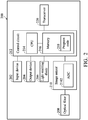
- FIG. 2 is a simplified functional block diagram of an examining device 200 according to one embodiment of the present disclosure. As shown in FIG. 2 , the examining device 200 can be the examining device 120 of FIG. 1 .
- the examining device 200 may include an input device 202, an output device 204, a light emitting diode 206, an optical filter 208, an image sensor 210, a control circuit 212 and a transceiver 220.
- the image sensor 210 can at least comprise an analog-to-digital converter (ADC) 2102.
- the control circuit 212 can comprise a central processing unit (CPU) 214 and a memory 216.
- the examining device 200 can receive signals input by a user through the input device 202, (such as a button) and can output images through the output device 204.
- the light emitting diode 206 can emit light including wavelength bands in the range from 370 nm to 430 nm when energized.
- the light emitting diode 122 can emit light including a wavelength of 405nm. The light mentioned above may effectively generate detectable fluorescent emissions between normal dental tissue and abnormal dental tissue.
- the optical filter 206 is used to filter the fluorescence.
- the optical filter 206 filters out light including a wavelength band that is less than about 450 nm.
- the optical filter 206 can filter out light not including wavelength bands selected from the ranges of 430 nm to 480 nm, 620 nm to 750 nm and combinations thereof.
- the optical filter 206 filters out light not including wavelength bands in the range from 450 nm to 680 nm.
- the image sensor 210 is coupled to the optical filter 206, receives the filtered fluorescence from the optical filter 206, and converts the filtered fluorescence into a digital signal by using the analog-to-digital converter 2102.
- the image sensor 210 can receive the signal input by the user through the input device 202 or the transceiver 220 to adjust a gain value of the analog-to-digital converter 2102.
- the analog-to-digital converter 2102 adjusts the digital signal according to the gain value, and transmits the adjusted digital signal to the control circuit 212.
- the CPU 214 in the control circuit 212 generates an output video signal that corresponds to the gain value after receiving the adjusted digital signal.
- the image sensor 210 adjusts the gain value that corresponds to a blue light channel of the analog-to-digital converter 2102 according to the signal input by the user to change the strength of the signal of the blue light in the output image signal.
- the memory 216 can store a program code 218.
- the control circuit 212 executes the program code 218 in the memory 216 through the CPU 214, thereby controlling the operation performed by the examining device 200.
- the transceiver 220 is used to receive and transmit wireless signals, delivering received signals to the control circuit 212, and outputting signals generated by the control circuit 212 wirelessly.
- FIG. 3 is a flow diagram 300 illustrating a method for dynamically adjusting fluorescent imaging according to an embodiment of the present disclosure. The method is used in the processor of the examining device 120 of FIG. 1 .
- a light emitting diode of the examining device emits light to illuminate teeth in an oral cavity, wherein the light is used to generate fluorescence from the teeth.
- an optical filter of the examining device filters the fluorescence.
- the optical filter filters out light including a wavelength band that is less than about 450 nanometers (nm).
- the optical filter can filter out light not including wavelength bands selected from the ranges of 430 nm to 480 nm, 620 nm to 750 nm and combinations thereof.
- the optical filter filters out light not including wavelength bands in the range from 450 nm to 680 nm.
- an image sensor of the examining device receives a signal and adjusts a gain value of an analog-to-digital converter according to the signal.
- the image sensor adjusts the gain value that corresponds to a blue light channel of the analog-to-digital converter according to the signal.
- step S320 the analog-to-digital converter of the examining device converts the filtered fluorescence into a digital signal and adjusts the digital signal according to the gain value.
- step S325 a processor of the examining device generates an output image signal that corresponds to the gain value from the digital signal.
- the examining device dynamically adjusts the gain value that corresponds to a blue channel of the analog-digital converter according to the received signal to achieve the effect of dynamically changing the fluorescence imaging.
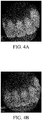
- FIGs. 4A-4D are schematic diagrams illustrating different output image signals output by the examining device according to the gain values of different analog-digital converters in accordance with an embodiment of the present disclosure.
- FIG. 4A is an image corresponding to a gain value of 16 of the analog-to-digital converter.
- FIG. 4B is an image corresponding to a gain value of 9 of the analog-to-digital converter.
- FIG. 4C is an image corresponding to a gain value of 7 of the analog-to-digital converter.
- FIG. 4D is an image corresponding to a gain value of 4 of the analog-to-digital converter.
- the lower the gain value of the analog-to-digital converter the lower the ratio of the blue channel in the image. In other words, the lower the gain value of the analog-to-digital converter, the yellower the color of the output image is.
- the method and device for dynamically adjusting fluorescent imaging in the present disclosure adjust the gain value of the analog-to-digital converter to dynamically change the proportion of blue light in the fluorescent imaging.
- different fluorescent imaging can be achieved without replacing the optical filter via the method and device for dynamically adjusting fluorescent imaging in the present disclosure.
- CPU 214 could execute the program code 218 to perform all of the above-described actions and steps or others described herein.
- the various illustrative logical blocks, modules, and circuits described in connection with the aspects disclosed herein may be implemented within or performed by an integrated circuit ("IC"), an access terminal, or an access point.
- the IC may comprise a general purpose processor, a digital signal processor (DSP), an application specific integrated circuit (ASIC), a field programmable gate array (FPGA) or another programmable logic device, discrete gate or transistor logic, discrete hardware components, electrical components, optical components, mechanical components, or any combination thereof designed to perform the functions described herein, and may execute codes or instructions that reside within the IC, outside of the IC, or both.
- a general-purpose processor may be a microprocessor, but in the alternative, the processor may be any processor, controller, microcontroller, or state machine.
- a processor may also be implemented as a combination of computing devices, e.g., a combination of a DSP and a microprocessor, a plurality of microprocessors, one or more microprocessors in conjunction with a DSP core, or any other such configuration.
Landscapes
- Health & Medical Sciences (AREA)
- Life Sciences & Earth Sciences (AREA)
- Surgery (AREA)
- Engineering & Computer Science (AREA)
- Molecular Biology (AREA)
- General Health & Medical Sciences (AREA)
- Veterinary Medicine (AREA)
- Physics & Mathematics (AREA)
- Public Health (AREA)
- Biophysics (AREA)
- Pathology (AREA)
- Biomedical Technology (AREA)
- Heart & Thoracic Surgery (AREA)
- Medical Informatics (AREA)
- Animal Behavior & Ethology (AREA)
- Oral & Maxillofacial Surgery (AREA)
- Dentistry (AREA)
- Audiology, Speech & Language Pathology (AREA)
- Optics & Photonics (AREA)
- Nuclear Medicine, Radiotherapy & Molecular Imaging (AREA)
- Radiology & Medical Imaging (AREA)
- Signal Processing (AREA)
- Physiology (AREA)
- Psychiatry (AREA)
- Computer Vision & Pattern Recognition (AREA)
- Artificial Intelligence (AREA)
- Multimedia (AREA)
- Endoscopes (AREA)
- Investigating, Analyzing Materials By Fluorescence Or Luminescence (AREA)
- Dental Tools And Instruments Or Auxiliary Dental Instruments (AREA)
Claims (8)
- Verfahren zum dynamischen Einstellen einer Fluoreszenzbildgebung, das in einer Vorrichtung (120, 200) verwendet wird, mit den Schritten:Emittieren von Licht durch eine Leuchtdiode (122, 206) zum Beleuchten von Zähnen (110) in einer Mundhöhle, wobei das Licht verwendet wird, um Fluoreszenz von den Zähnen (110) zu erzeugen;Filtern der Fluoreszenz durch ein optisches Filter (124, 208);Empfangen eines durch einen Benutzer eingegebenen Einstellsignals durch einen Bildsensor (210) und Einstellen eines Verstärkungswerts eines Analog-Digital-Wandlers (2102) gemäß dem Signal;Umwandeln der gefilterten Fluoreszenz in ein Digitalsignal durch den Analog-Digital-Wandler (2102) und Einstellen des Digitalsignals gemäß dem Verstärkungswert; undErzeugen eines Ausgangsbildsignals, das dem Verstärkungswert entspricht, aus dem Digitalsignal durch einen Prozessor (214),dadurch gekennzeichnet, dassder Bildsensor (210) den Verstärkungswert, der einem Blaulichtkanal des Analog-Digital-Wandlers (2102) entspricht, gemäß dem Einstellsignal einstellt.
- Verfahren nach Anspruch 1, wobei das optische Filter (124, 208) Licht herausfiltert, das ein Wellenlängenband enthält, das niedriger ist als etwa 450 Nanometer, nm.
- Verfahren nach Anspruch 1, wobei das optische Filter (124, 208) Licht herausfiltert, das keine Wellenlängenbänder enthält, die aus den Bereichen von 430 nm bis 480 nm, 620 nm bis 750 nm und Kombinationen davon ausgewählt sind.
- Verfahren nach Anspruch 1, wobei das optische Filter (124, 208) Licht herausfiltert, das keine Wellenlängenbänder im Bereich von 450 nm bis 680 nm enthält.
- Vorrichtung (120, 200) zum dynamischen Einstellen einer Fluoreszenzbildgebung, mit:einer Leuchtdiode (122, 206), die Licht zum Beleuchten von Zähnen (110) in einer Mundhöhle emittiert, wobei das Licht verwendet wird, um Fluoreszenz von den Zähnen (110) zu erzeugen;einem optischen Filter (124, 208), das die Fluoreszenz filtert;einem Bildsensor (210), der mit dem optischen Filter (124, 208) verbunden ist und ein durch einen Benutzer eingegebenes Einstellsignal empfängt, mit:
einem Analog-Digital-Wandler (2102), der die gefilterte Fluoreszenz in ein Digitalsignal umwandelt; undeinem Prozessor (214), der mit dem Bildsensor (210) verbunden ist und ein Ausgangsvideosignal von dem Digitalsignal erzeugt, wobeider Bildsensor (210) einen Verstärkungswert des Analog-Digital-Wandlers (2102) gemäß dem Signal einstellt und der Analog-Digital-Wandler (2102) das Digitalsignal gemäß dem Verstärkungswert einstellt, so dass der Prozessor (214) ein Ausgangsbildsignal erzeugt, das dem Verstärkungswert entspricht;dadurch gekennzeichnet, dassder Bildsensor (210) den Verstärkungswert, der einem Blaulichtkanal des Analog-Digital-Wandlers (2102) entspricht, gemäß dem Einstellsignal einstellt. - Vorrichtung (120, 200) nach Anspruch 5, wobei das optische Filter (124, 208) Licht mit einem Wellenlängenband herausfiltert, das niedriger ist als etwa 450 Nanometer, nm.
- Vorrichtung (120, 200) nach Anspruch 5, wobei das optische Filter (124, 208) Licht herausfiltert, das keine Wellenlängenbänder enthält, die ausgewählt sind aus den Bereichen von 430 nm bis 480 nm, 620 nm bis 750 nm und Kombinationen davon.
- Vorrichtung (120, 200) nach Anspruch 6, wobei das optische Filter (124, 208) Licht herausfiltert, das keine Wellenlängenbänder im Bereich von 450 nm bis 680 nm enthält.
Applications Claiming Priority (1)
| Application Number | Priority Date | Filing Date | Title |
|---|---|---|---|
| TW107116766A TWI667999B (zh) | 2018-05-17 | 2018-05-17 | 動態調整螢光成像的方法及裝置 |
Publications (2)
| Publication Number | Publication Date |
|---|---|
| EP3569141A1 EP3569141A1 (de) | 2019-11-20 |
| EP3569141B1 true EP3569141B1 (de) | 2021-01-27 |
Family
ID=64901282
Family Applications (1)
| Application Number | Title | Priority Date | Filing Date |
|---|---|---|---|
| EP18209318.7A Active EP3569141B1 (de) | 2018-05-17 | 2018-11-29 | Verfahren und vorrichtung zur dynamischen anpassung von fluoreszierender bildgebung |
Country Status (5)
| Country | Link |
|---|---|
| US (1) | US10791935B2 (de) |
| EP (1) | EP3569141B1 (de) |
| JP (1) | JP6745326B2 (de) |
| CN (1) | CN110495853B (de) |
| TW (1) | TWI667999B (de) |
Families Citing this family (2)
| Publication number | Priority date | Publication date | Assignee | Title |
|---|---|---|---|---|
| KR102553367B1 (ko) * | 2021-08-17 | 2023-07-10 | ㈜ 엘프스 | 자가융착형 도전접속필름용 수지조성물, 이를 포함하는 자가융착형 도전접속필름 및 이의 제조방법 |
| TWI818372B (zh) * | 2021-12-03 | 2023-10-11 | 財團法人金屬工業研究發展中心 | 口腔檢測系統 |
Citations (1)
| Publication number | Priority date | Publication date | Assignee | Title |
|---|---|---|---|---|
| US20160287084A1 (en) * | 2012-12-19 | 2016-10-06 | Koninklijke Philips N.V. | Dental apparatus and method of utilizing the same |
Family Cites Families (24)
| Publication number | Priority date | Publication date | Assignee | Title |
|---|---|---|---|---|
| CA2108813C (en) | 1992-10-23 | 2002-08-06 | Shinobu Arimoto | Photo-sensor and image processing apparatus |
| US6660228B1 (en) | 1998-03-02 | 2003-12-09 | Cepheid | Apparatus for performing heat-exchanging, chemical reactions |
| JP2001309393A (ja) * | 2000-04-19 | 2001-11-02 | Olympus Optical Co Ltd | 撮像装置 |
| US6960165B2 (en) * | 2001-05-16 | 2005-11-01 | Olympus Corporation | Endoscope with a single image pick-up element for fluorescent and normal-light images |
| JP2004089236A (ja) * | 2002-08-29 | 2004-03-25 | Matsushita Electric Ind Co Ltd | 歯観察装置 |
| JP4575208B2 (ja) | 2005-03-30 | 2010-11-04 | オリンパスメディカルシステムズ株式会社 | 電子内視鏡装置 |
| US7596253B2 (en) * | 2005-10-31 | 2009-09-29 | Carestream Health, Inc. | Method and apparatus for detection of caries |
| US8050519B2 (en) * | 2005-12-19 | 2011-11-01 | Olympus Corporation | Image combining apparatus |
| CN101141594A (zh) * | 2006-09-05 | 2008-03-12 | 明基电通股份有限公司 | 显示装置及其亮度调整方法 |
| US8270689B2 (en) * | 2006-09-12 | 2012-09-18 | Carestream Health, Inc. | Apparatus for caries detection |
| JP5325381B2 (ja) * | 2006-10-02 | 2013-10-23 | 株式会社ジーシー | 口腔内観察装置 |
| US7702139B2 (en) * | 2006-10-13 | 2010-04-20 | Carestream Health, Inc. | Apparatus for caries detection |
| DE102007014413B4 (de) | 2007-03-17 | 2016-02-04 | DüRR DENTAL AG | Verfahren zum Auswerten von Fluoreszenzbildsätzen und Vorrichtung zu seiner Durchführung |
| JP2009095538A (ja) | 2007-10-18 | 2009-05-07 | Hoya Corp | 内視鏡装置の電子内視鏡 |
| US7929151B2 (en) * | 2008-01-11 | 2011-04-19 | Carestream Health, Inc. | Intra-oral camera for diagnostic and cosmetic imaging |
| US8314377B2 (en) | 2009-12-23 | 2012-11-20 | Mcneil-Ppc, Inc. | Device and method for detecting plaque in the oral cavity |
| US8702422B2 (en) | 2010-06-29 | 2014-04-22 | Mcneil-Ppc, Inc. | Device and method for cleaning the oral cavity |
| JP5258869B2 (ja) * | 2010-12-13 | 2013-08-07 | 富士フイルム株式会社 | 内視鏡装置 |
| WO2012172908A1 (ja) * | 2011-06-14 | 2012-12-20 | オリンパスメディカルシステムズ株式会社 | 医療機器 |
| JP5948203B2 (ja) * | 2011-10-12 | 2016-07-06 | 富士フイルム株式会社 | 内視鏡システム及びその作動方法 |
| WO2015082390A1 (en) * | 2013-12-02 | 2015-06-11 | Koninklijke Philips N.V. | Device for the detection of plaque on teeth |
| JP6399749B2 (ja) | 2013-12-19 | 2018-10-03 | キヤノン株式会社 | 撮像装置および撮像システム |
| US11076771B2 (en) * | 2016-09-22 | 2021-08-03 | Apple Inc. | Systems and methods for determining physiological signals using ambient light |
| CN106821529B (zh) * | 2017-02-28 | 2018-12-11 | 厦门罗雅光科技有限公司 | 便携式牙齿检查装置及其控制方法 |
-
2018
- 2018-05-17 TW TW107116766A patent/TWI667999B/zh active
- 2018-05-30 CN CN201810538119.2A patent/CN110495853B/zh active Active
- 2018-10-11 US US16/157,312 patent/US10791935B2/en active Active
- 2018-11-29 EP EP18209318.7A patent/EP3569141B1/de active Active
- 2018-12-25 JP JP2018241549A patent/JP6745326B2/ja active Active
Patent Citations (1)
| Publication number | Priority date | Publication date | Assignee | Title |
|---|---|---|---|---|
| US20160287084A1 (en) * | 2012-12-19 | 2016-10-06 | Koninklijke Philips N.V. | Dental apparatus and method of utilizing the same |
Also Published As
| Publication number | Publication date |
|---|---|
| JP2019198624A (ja) | 2019-11-21 |
| US20190350461A1 (en) | 2019-11-21 |
| TWI667999B (zh) | 2019-08-11 |
| EP3569141A1 (de) | 2019-11-20 |
| CN110495853A (zh) | 2019-11-26 |
| JP6745326B2 (ja) | 2020-08-26 |
| TW201946597A (zh) | 2019-12-16 |
| CN110495853B (zh) | 2022-10-04 |
| US10791935B2 (en) | 2020-10-06 |
Similar Documents
| Publication | Publication Date | Title |
|---|---|---|
| EP2261690B1 (de) | Bildsensor zum Messen der Beleuchtung, Nähe und Farbtemperatur | |
| EP2904956B1 (de) | Endoskopsystem, Prozessorvorrichtung für ein Endoskopsystem, Betriebsverfahren für ein Endoskopsystem und Betriebsverfahren für eine Prozessorvorrichtung | |
| US6118521A (en) | Apparatus and method for measuring optical characteristics of an object | |
| EP0025958A2 (de) | Endoskopapparat mit Doppelübertragungsfunktion | |
| EP2912991B1 (de) | Endoskopsystem und Betriebsverfahren für das Endoskopsystem | |
| US11266304B2 (en) | Minimizing image sensor input/output in a pulsed hyperspectral imaging system | |
| EP2901914B1 (de) | Endoskopsystem | |
| EP2356935B1 (de) | Bildverarbeitungssystem, bildgebungsvorrichtung, empfangsvorrichtung und bildanzeigevorrichtung | |
| EP2912990A1 (de) | Endoskopsystem, Endoskopsystemprozessorvorrichtung, Betriebsverfahren für das Endoskopsystem und Betriebsverfahren für die Endoskopsystemprozessorvorrichtung | |
| US11471034B2 (en) | Method and device for distinguishing plaque and calculus | |
| US10791935B2 (en) | Method and device for dynamically adjusting fluorescent imaging | |
| EP2868260A1 (de) | Vorrichtung, verfahren und programm zur gesundheitsmanagementunterstützung | |
| JPWO2012132380A1 (ja) | 光学特性測定装置および該方法 | |
| EP2700350A1 (de) | Medizinische Kamera mit Auswahl verschiedener Betriebsmodus | |
| WO2019017051A1 (ja) | 光源システム、制御装置および制御方法 | |
| EP2482225A1 (de) | Endgerät mit optischer Bildgebungsanordnung | |
| JP2006071589A (ja) | 色測定装置及び光源装置 | |
| WO2024007117A1 (en) | Oral scanner system | |
| JP2015112208A (ja) | 医用システム | |
| EP4551095A1 (de) | Orales scannersystem | |
| JP2010162121A (ja) | 撮像装置、撮像方法、及びプログラム | |
| JP2008086554A (ja) | 口腔内観察装置 | |
| US10980424B2 (en) | Oral care evaluation system and process | |
| JP4175358B2 (ja) | 光学情報読取装置 | |
| IT202300003390A1 (it) | Dispositivo di rilevazione di placca dentale |
Legal Events
| Date | Code | Title | Description |
|---|---|---|---|
| PUAI | Public reference made under article 153(3) epc to a published international application that has entered the european phase |
Free format text: ORIGINAL CODE: 0009012 |
|
| STAA | Information on the status of an ep patent application or granted ep patent |
Free format text: STATUS: THE APPLICATION HAS BEEN PUBLISHED |
|
| AK | Designated contracting states |
Kind code of ref document: A1 Designated state(s): AL AT BE BG CH CY CZ DE DK EE ES FI FR GB GR HR HU IE IS IT LI LT LU LV MC MK MT NL NO PL PT RO RS SE SI SK SM TR |
|
| AX | Request for extension of the european patent |
Extension state: BA ME |
|
| STAA | Information on the status of an ep patent application or granted ep patent |
Free format text: STATUS: REQUEST FOR EXAMINATION WAS MADE |
|
| 17P | Request for examination filed |
Effective date: 20200519 |
|
| RBV | Designated contracting states (corrected) |
Designated state(s): AL AT BE BG CH CY CZ DE DK EE ES FI FR GB GR HR HU IE IS IT LI LT LU LV MC MK MT NL NO PL PT RO RS SE SI SK SM TR |
|
| GRAP | Despatch of communication of intention to grant a patent |
Free format text: ORIGINAL CODE: EPIDOSNIGR1 |
|
| STAA | Information on the status of an ep patent application or granted ep patent |
Free format text: STATUS: GRANT OF PATENT IS INTENDED |
|
| INTG | Intention to grant announced |
Effective date: 20200925 |
|
| GRAS | Grant fee paid |
Free format text: ORIGINAL CODE: EPIDOSNIGR3 |
|
| GRAA | (expected) grant |
Free format text: ORIGINAL CODE: 0009210 |
|
| STAA | Information on the status of an ep patent application or granted ep patent |
Free format text: STATUS: THE PATENT HAS BEEN GRANTED |
|
| AK | Designated contracting states |
Kind code of ref document: B1 Designated state(s): AL AT BE BG CH CY CZ DE DK EE ES FI FR GB GR HR HU IE IS IT LI LT LU LV MC MK MT NL NO PL PT RO RS SE SI SK SM TR |
|
| REG | Reference to a national code |
Ref country code: GB Ref legal event code: FG4D |
|
| REG | Reference to a national code |
Ref country code: CH Ref legal event code: EP |
|
| REG | Reference to a national code |
Ref country code: AT Ref legal event code: REF Ref document number: 1357618 Country of ref document: AT Kind code of ref document: T Effective date: 20210215 |
|
| REG | Reference to a national code |
Ref country code: IE Ref legal event code: FG4D |
|
| REG | Reference to a national code |
Ref country code: DE Ref legal event code: R096 Ref document number: 602018012254 Country of ref document: DE |
|
| REG | Reference to a national code |
Ref country code: NL Ref legal event code: MP Effective date: 20210127 |
|
| REG | Reference to a national code |
Ref country code: LT Ref legal event code: MG9D |
|
| REG | Reference to a national code |
Ref country code: AT Ref legal event code: MK05 Ref document number: 1357618 Country of ref document: AT Kind code of ref document: T Effective date: 20210127 |
|
| PG25 | Lapsed in a contracting state [announced via postgrant information from national office to epo] |
Ref country code: BG Free format text: LAPSE BECAUSE OF FAILURE TO SUBMIT A TRANSLATION OF THE DESCRIPTION OR TO PAY THE FEE WITHIN THE PRESCRIBED TIME-LIMIT Effective date: 20210427 Ref country code: HR Free format text: LAPSE BECAUSE OF FAILURE TO SUBMIT A TRANSLATION OF THE DESCRIPTION OR TO PAY THE FEE WITHIN THE PRESCRIBED TIME-LIMIT Effective date: 20210127 Ref country code: FI Free format text: LAPSE BECAUSE OF FAILURE TO SUBMIT A TRANSLATION OF THE DESCRIPTION OR TO PAY THE FEE WITHIN THE PRESCRIBED TIME-LIMIT Effective date: 20210127 Ref country code: GR Free format text: LAPSE BECAUSE OF FAILURE TO SUBMIT A TRANSLATION OF THE DESCRIPTION OR TO PAY THE FEE WITHIN THE PRESCRIBED TIME-LIMIT Effective date: 20210428 Ref country code: PT Free format text: LAPSE BECAUSE OF FAILURE TO SUBMIT A TRANSLATION OF THE DESCRIPTION OR TO PAY THE FEE WITHIN THE PRESCRIBED TIME-LIMIT Effective date: 20210527 Ref country code: NO Free format text: LAPSE BECAUSE OF FAILURE TO SUBMIT A TRANSLATION OF THE DESCRIPTION OR TO PAY THE FEE WITHIN THE PRESCRIBED TIME-LIMIT Effective date: 20210427 Ref country code: LT Free format text: LAPSE BECAUSE OF FAILURE TO SUBMIT A TRANSLATION OF THE DESCRIPTION OR TO PAY THE FEE WITHIN THE PRESCRIBED TIME-LIMIT Effective date: 20210127 |
|
| PG25 | Lapsed in a contracting state [announced via postgrant information from national office to epo] |
Ref country code: AT Free format text: LAPSE BECAUSE OF FAILURE TO SUBMIT A TRANSLATION OF THE DESCRIPTION OR TO PAY THE FEE WITHIN THE PRESCRIBED TIME-LIMIT Effective date: 20210127 Ref country code: LV Free format text: LAPSE BECAUSE OF FAILURE TO SUBMIT A TRANSLATION OF THE DESCRIPTION OR TO PAY THE FEE WITHIN THE PRESCRIBED TIME-LIMIT Effective date: 20210127 Ref country code: PL Free format text: LAPSE BECAUSE OF FAILURE TO SUBMIT A TRANSLATION OF THE DESCRIPTION OR TO PAY THE FEE WITHIN THE PRESCRIBED TIME-LIMIT Effective date: 20210127 Ref country code: RS Free format text: LAPSE BECAUSE OF FAILURE TO SUBMIT A TRANSLATION OF THE DESCRIPTION OR TO PAY THE FEE WITHIN THE PRESCRIBED TIME-LIMIT Effective date: 20210127 Ref country code: SE Free format text: LAPSE BECAUSE OF FAILURE TO SUBMIT A TRANSLATION OF THE DESCRIPTION OR TO PAY THE FEE WITHIN THE PRESCRIBED TIME-LIMIT Effective date: 20210127 |
|
| PG25 | Lapsed in a contracting state [announced via postgrant information from national office to epo] |
Ref country code: IS Free format text: LAPSE BECAUSE OF FAILURE TO SUBMIT A TRANSLATION OF THE DESCRIPTION OR TO PAY THE FEE WITHIN THE PRESCRIBED TIME-LIMIT Effective date: 20210527 |
|
| REG | Reference to a national code |
Ref country code: DE Ref legal event code: R097 Ref document number: 602018012254 Country of ref document: DE |
|
| PG25 | Lapsed in a contracting state [announced via postgrant information from national office to epo] |
Ref country code: SM Free format text: LAPSE BECAUSE OF FAILURE TO SUBMIT A TRANSLATION OF THE DESCRIPTION OR TO PAY THE FEE WITHIN THE PRESCRIBED TIME-LIMIT Effective date: 20210127 Ref country code: EE Free format text: LAPSE BECAUSE OF FAILURE TO SUBMIT A TRANSLATION OF THE DESCRIPTION OR TO PAY THE FEE WITHIN THE PRESCRIBED TIME-LIMIT Effective date: 20210127 Ref country code: CZ Free format text: LAPSE BECAUSE OF FAILURE TO SUBMIT A TRANSLATION OF THE DESCRIPTION OR TO PAY THE FEE WITHIN THE PRESCRIBED TIME-LIMIT Effective date: 20210127 |
|
| PG25 | Lapsed in a contracting state [announced via postgrant information from national office to epo] |
Ref country code: DK Free format text: LAPSE BECAUSE OF FAILURE TO SUBMIT A TRANSLATION OF THE DESCRIPTION OR TO PAY THE FEE WITHIN THE PRESCRIBED TIME-LIMIT Effective date: 20210127 Ref country code: RO Free format text: LAPSE BECAUSE OF FAILURE TO SUBMIT A TRANSLATION OF THE DESCRIPTION OR TO PAY THE FEE WITHIN THE PRESCRIBED TIME-LIMIT Effective date: 20210127 Ref country code: SK Free format text: LAPSE BECAUSE OF FAILURE TO SUBMIT A TRANSLATION OF THE DESCRIPTION OR TO PAY THE FEE WITHIN THE PRESCRIBED TIME-LIMIT Effective date: 20210127 |
|
| PLBE | No opposition filed within time limit |
Free format text: ORIGINAL CODE: 0009261 |
|
| STAA | Information on the status of an ep patent application or granted ep patent |
Free format text: STATUS: NO OPPOSITION FILED WITHIN TIME LIMIT |
|
| 26N | No opposition filed |
Effective date: 20211028 |
|
| PG25 | Lapsed in a contracting state [announced via postgrant information from national office to epo] |
Ref country code: ES Free format text: LAPSE BECAUSE OF FAILURE TO SUBMIT A TRANSLATION OF THE DESCRIPTION OR TO PAY THE FEE WITHIN THE PRESCRIBED TIME-LIMIT Effective date: 20210127 Ref country code: AL Free format text: LAPSE BECAUSE OF FAILURE TO SUBMIT A TRANSLATION OF THE DESCRIPTION OR TO PAY THE FEE WITHIN THE PRESCRIBED TIME-LIMIT Effective date: 20210127 |
|
| PG25 | Lapsed in a contracting state [announced via postgrant information from national office to epo] |
Ref country code: SI Free format text: LAPSE BECAUSE OF FAILURE TO SUBMIT A TRANSLATION OF THE DESCRIPTION OR TO PAY THE FEE WITHIN THE PRESCRIBED TIME-LIMIT Effective date: 20210127 |
|
| PG25 | Lapsed in a contracting state [announced via postgrant information from national office to epo] |
Ref country code: IT Free format text: LAPSE BECAUSE OF FAILURE TO SUBMIT A TRANSLATION OF THE DESCRIPTION OR TO PAY THE FEE WITHIN THE PRESCRIBED TIME-LIMIT Effective date: 20210127 |
|
| PG25 | Lapsed in a contracting state [announced via postgrant information from national office to epo] |
Ref country code: IS Free format text: LAPSE BECAUSE OF FAILURE TO SUBMIT A TRANSLATION OF THE DESCRIPTION OR TO PAY THE FEE WITHIN THE PRESCRIBED TIME-LIMIT Effective date: 20210527 |
|
| PG25 | Lapsed in a contracting state [announced via postgrant information from national office to epo] |
Ref country code: MC Free format text: LAPSE BECAUSE OF FAILURE TO SUBMIT A TRANSLATION OF THE DESCRIPTION OR TO PAY THE FEE WITHIN THE PRESCRIBED TIME-LIMIT Effective date: 20210127 |
|
| REG | Reference to a national code |
Ref country code: CH Ref legal event code: PL |
|
| PG25 | Lapsed in a contracting state [announced via postgrant information from national office to epo] |
Ref country code: LU Free format text: LAPSE BECAUSE OF NON-PAYMENT OF DUE FEES Effective date: 20211129 Ref country code: BE Free format text: LAPSE BECAUSE OF NON-PAYMENT OF DUE FEES Effective date: 20211130 |
|
| REG | Reference to a national code |
Ref country code: BE Ref legal event code: MM Effective date: 20211130 |
|
| PG25 | Lapsed in a contracting state [announced via postgrant information from national office to epo] |
Ref country code: LI Free format text: LAPSE BECAUSE OF NON-PAYMENT OF DUE FEES Effective date: 20211130 Ref country code: CH Free format text: LAPSE BECAUSE OF NON-PAYMENT OF DUE FEES Effective date: 20211130 |
|
| PG25 | Lapsed in a contracting state [announced via postgrant information from national office to epo] |
Ref country code: IE Free format text: LAPSE BECAUSE OF NON-PAYMENT OF DUE FEES Effective date: 20211129 |
|
| PG25 | Lapsed in a contracting state [announced via postgrant information from national office to epo] |
Ref country code: NL Free format text: LAPSE BECAUSE OF NON-PAYMENT OF DUE FEES Effective date: 20210127 Ref country code: CY Free format text: LAPSE BECAUSE OF FAILURE TO SUBMIT A TRANSLATION OF THE DESCRIPTION OR TO PAY THE FEE WITHIN THE PRESCRIBED TIME-LIMIT Effective date: 20210127 |
|
| PG25 | Lapsed in a contracting state [announced via postgrant information from national office to epo] |
Ref country code: HU Free format text: LAPSE BECAUSE OF FAILURE TO SUBMIT A TRANSLATION OF THE DESCRIPTION OR TO PAY THE FEE WITHIN THE PRESCRIBED TIME-LIMIT; INVALID AB INITIO Effective date: 20181129 |
|
| PG25 | Lapsed in a contracting state [announced via postgrant information from national office to epo] |
Ref country code: MK Free format text: LAPSE BECAUSE OF FAILURE TO SUBMIT A TRANSLATION OF THE DESCRIPTION OR TO PAY THE FEE WITHIN THE PRESCRIBED TIME-LIMIT Effective date: 20210127 |
|
| PG25 | Lapsed in a contracting state [announced via postgrant information from national office to epo] |
Ref country code: MT Free format text: LAPSE BECAUSE OF FAILURE TO SUBMIT A TRANSLATION OF THE DESCRIPTION OR TO PAY THE FEE WITHIN THE PRESCRIBED TIME-LIMIT Effective date: 20210127 |
|
| PGFP | Annual fee paid to national office [announced via postgrant information from national office to epo] |
Ref country code: GB Payment date: 20250930 Year of fee payment: 8 |
|
| PGFP | Annual fee paid to national office [announced via postgrant information from national office to epo] |
Ref country code: FR Payment date: 20250930 Year of fee payment: 8 |
|
| PG25 | Lapsed in a contracting state [announced via postgrant information from national office to epo] |
Ref country code: TR Free format text: LAPSE BECAUSE OF FAILURE TO SUBMIT A TRANSLATION OF THE DESCRIPTION OR TO PAY THE FEE WITHIN THE PRESCRIBED TIME-LIMIT Effective date: 20210127 |
|
| PGFP | Annual fee paid to national office [announced via postgrant information from national office to epo] |
Ref country code: DE Payment date: 20250930 Year of fee payment: 8 |