EP3569003B1 - Elektronische vorrichtung und verfahren zur steuerung der kommunikation davon - Google Patents
Elektronische vorrichtung und verfahren zur steuerung der kommunikation davon Download PDFInfo
- Publication number
- EP3569003B1 EP3569003B1 EP18757188.0A EP18757188A EP3569003B1 EP 3569003 B1 EP3569003 B1 EP 3569003B1 EP 18757188 A EP18757188 A EP 18757188A EP 3569003 B1 EP3569003 B1 EP 3569003B1
- Authority
- EP
- European Patent Office
- Prior art keywords
- electronic device
- mode
- processor
- cycle
- operating cycle
- Prior art date
- Legal status (The legal status is an assumption and is not a legal conclusion. Google has not performed a legal analysis and makes no representation as to the accuracy of the status listed.)
- Active
Links
Images





Classifications
-
- H—ELECTRICITY
- H04—ELECTRIC COMMUNICATION TECHNIQUE
- H04W—WIRELESS COMMUNICATION NETWORKS
- H04W52/00—Power management, e.g. Transmission Power Control [TPC] or power classes
- H04W52/02—Power saving arrangements
- H04W52/0209—Power saving arrangements in terminal devices
- H04W52/0212—Power saving arrangements in terminal devices managed by the network, e.g. network or access point is leader and terminal is follower
- H04W52/0216—Power saving arrangements in terminal devices managed by the network, e.g. network or access point is leader and terminal is follower using a pre-established activity schedule, e.g. traffic indication frame
-
- H—ELECTRICITY
- H04—ELECTRIC COMMUNICATION TECHNIQUE
- H04W—WIRELESS COMMUNICATION NETWORKS
- H04W4/00—Services specially adapted for wireless communication networks; Facilities therefor
- H04W4/02—Services making use of location information
- H04W4/021—Services related to particular areas, e.g. point of interest [POI] services, venue services or geofences
-
- H—ELECTRICITY
- H04—ELECTRIC COMMUNICATION TECHNIQUE
- H04L—TRANSMISSION OF DIGITAL INFORMATION, e.g. TELEGRAPHIC COMMUNICATION
- H04L67/00—Network arrangements or protocols for supporting network services or applications
- H04L67/01—Protocols
- H04L67/12—Protocols specially adapted for proprietary or special-purpose networking environments, e.g. medical networks, sensor networks, networks in vehicles or remote metering networks
-
- H—ELECTRICITY
- H04—ELECTRIC COMMUNICATION TECHNIQUE
- H04W—WIRELESS COMMUNICATION NETWORKS
- H04W52/00—Power management, e.g. Transmission Power Control [TPC] or power classes
- H04W52/02—Power saving arrangements
- H04W52/0209—Power saving arrangements in terminal devices
- H04W52/0251—Power saving arrangements in terminal devices using monitoring of local events, e.g. events related to user activity
-
- H—ELECTRICITY
- H04—ELECTRIC COMMUNICATION TECHNIQUE
- H04W—WIRELESS COMMUNICATION NETWORKS
- H04W52/00—Power management, e.g. Transmission Power Control [TPC] or power classes
- H04W52/02—Power saving arrangements
- H04W52/0209—Power saving arrangements in terminal devices
- H04W52/0251—Power saving arrangements in terminal devices using monitoring of local events, e.g. events related to user activity
- H04W52/0254—Power saving arrangements in terminal devices using monitoring of local events, e.g. events related to user activity detecting a user operation or a tactile contact or a motion of the device
-
- H—ELECTRICITY
- H04—ELECTRIC COMMUNICATION TECHNIQUE
- H04W—WIRELESS COMMUNICATION NETWORKS
- H04W88/00—Devices specially adapted for wireless communication networks, e.g. terminals, base stations or access point devices
- H04W88/02—Terminal devices
-
- Y—GENERAL TAGGING OF NEW TECHNOLOGICAL DEVELOPMENTS; GENERAL TAGGING OF CROSS-SECTIONAL TECHNOLOGIES SPANNING OVER SEVERAL SECTIONS OF THE IPC; TECHNICAL SUBJECTS COVERED BY FORMER USPC CROSS-REFERENCE ART COLLECTIONS [XRACs] AND DIGESTS
- Y02—TECHNOLOGIES OR APPLICATIONS FOR MITIGATION OR ADAPTATION AGAINST CLIMATE CHANGE
- Y02D—CLIMATE CHANGE MITIGATION TECHNOLOGIES IN INFORMATION AND COMMUNICATION TECHNOLOGIES [ICT], I.E. INFORMATION AND COMMUNICATION TECHNOLOGIES AIMING AT THE REDUCTION OF THEIR OWN ENERGY USE
- Y02D30/00—Reducing energy consumption in communication networks
- Y02D30/70—Reducing energy consumption in communication networks in wireless communication networks
Definitions
- the present disclosure generally relates to a communication control method and an electronic device implementing the method.
- IoT Internet of Things
- ITU-T The ITU Telecommunication Standardization Sector
- IT information technology
- IoT services are techniques that provide additional conveniences to the users.
- Today, many mobile communication operators and device manufacturers are concentrating on the development of IoT devices and services.
- WO 2013/035984 A1 relates to an operation method performed by user equipment in a wireless communication system.
- the method includes: determining whether to switch a Discontinuous Reception (DRX) state; switching to a new DRX state and operating in the new DRX state, if it is determined to switch to the DRX state; and reporting the switch to the new DRX state to a network.
- DRX Discontinuous Reception
- US 2013/210425 A1 relates to a method and apparatus for a wireless device that can adapt a rate of related wireless network unit scans for adjacent networks.
- the wireless device can include a wireless network unit and a co-located geo-location signal receiver, and a processor.
- the processor can determine the position and speed of the wireless device from data received from the geo-location signal receiver.
- WO 2011/022412 A1 relates to an apparatus, method and system for contextually aware monitoring of a supply chain.
- Contextually aware monitoring can include monitoring of the supply chain tradelane with tracking devices including sensors for determining location, velocity, heading, vibration, acceleration (e.g., 3D acceleration), or any other sensor that can monitor the environment of the shipping container to provide contextual awareness.
- US 2011/171909 A1 relates to a method and an apparatus for automatically connecting a short range wireless network in a portable terminal.
- the method includes, when registering to an Access Point (AP), storing location information of the AP.
- the method also includes obtaining location information of the terminal.
- AP Access Point
- Various embodiments of the present disclosure provide an electronic device that may be used as an IoT device, and a communication control method thereof for dynamically changing the communication activating cycle and the location measuring cycle of the device.
- the terms suchas “include” or “have” may be construed to indicate the presence of a certain characteristic, number,step, operation, constituent element, component or a combination thereof, butmay not be construed to exclude the existence of or a possibility of addition of one or more other characteristics, numbers,steps, operations, constituent elements, components or combinations thereof.
- the expression “or” or “at least one of A or/and B” includes any or all of combinations of words listed together.
- the expression “A or B” or “at least A or/and B” may include A, may include B, or may include both A and B.
- first and second may refer to corresponding components without implying an order of importance, and are used merely to distinguish each component from the others without unduly limiting the components.
- a first user device and a second user device indicate different user devices although both of them are user devices.
- a first structural element may be referred to as a second structural element.
- the second structural element also may be referred to as the first structural element.
- a component When it is stated that a component is “coupled to” or “connected to” another component, the component may be directly coupled or connected to another component or a new component may exist between the component and another component. In contrast, when it is stated that a component is “directly coupled to” or “directly connected to” another component, a new component does not exist between the component and another component.
- An electronic device may be a device that performs communication functions.
- the electronic device may be one or a combination of a smart phone, a tablet Personal Computer (PC), a mobile phone, a video phone, an e-book reader, a desktop PC, a laptop PC, a netbook computer, a Personal Digital Assistant (PDA), a camera, a wearable device (for example, a Head-Mounted-Device (HMD) suchas electronic glasses, electronic clothes, and electronic bracelet, an electronic necklace, an electronic appcessary, an electronic tattoo, and a smart watch.
- HMD Head-Mounted-Device
- the electronic device may be a smart home appliance having a communication function.
- the smart home appliance may include at least one of a Television (TV), a Digital Video Disk (DVD) player, an audioplayer, an air conditioner, a cleaner, an oven, a microwave oven, a washing machine, an air cleaner, a set-top box, a TV box (for example, Samsung HomeSyncTM, Apple TVTM, or Google TVTM), game consoles, an electronic dictionary, an electronic key, a camcorder, and an electronic frame.
- TV Television
- DVD Digital Video Disk
- the electronic device may include at least one of various types of medical devices (for example, Magnetic Resonance Angiography (MRA), Magnetic Resonance Imaging (MRI), Computed Tomography (CT), a scanner, an ultrasonic device and the like), a navigation device, a Global Navigation Satellite System (GNSS) receiver, an Event Data Recorder (EDR), a Flight Data Recorder (FDR), a vehicle infotainment device, electronic equipment for a ship (for example, a navigation device for ship, a gyro compass and the like), avionics, a security device, a head unit for a vehicle, an industrial or home robot, an Automatic Teller Machine (ATM) of financial institutions, and a Point Of Sale (POS) device of shops.
- MRA Magnetic Resonance Angiography
- MRI Magnetic Resonance Imaging
- CT Computed Tomography
- a scanner an ultrasonic device and the like
- a navigation device for example, a Global Navigation Satellite System (GNSS) receiver, an Event Data Record
- the electronic device may include at least one of furnitureor a part of a building/structure,an electronic board, an electronic signature receiving device, a projector, and various types of measuring devices (for example, a water meter, an electricity meter, a gas meter, a radio wave meter and the like) including a camera function.
- the electronic device according to various embodiments of the present disclosure may be one or a combination of the above described various devices. Further, the electronic device according to various embodiments of the present disclosure may be a flexible device. It is apparent to those skilled in the art that the electronic device according to various embodiments of the present disclosure is not limited to the above described devices.
- the term "user” usedin various embodiments may refer to a person who uses an electronic device or a device (for example, an artificial intelligence electronic device) which uses an electronic device.
- a screen of an electronic device may be split into at least two windows according to a predefined split manner and displayed through a display of an electronic device.
- the windows are defined as split windows.
- the split windows are defined as windows displayed on a display of an electronic display not to be superposedone on another.
- a popup window is defined as a window displayed on a display of an electronic device to hide or to be superposedon a portion of a screen under execution.
- an electronic device using split window and a popup window is capable of displaying two or more application execution screens or functionexecution screens.
- the split windows and the popup window are defined as a multi-window.
- the term "user” may indicate a person who uses an electronic device or a device (e.g., an artificial intelligence electronic device) that uses an electronic device.
- FIG. 1 illustrates a network environment 10 including an electronic device 101 according to an embodiment of the present disclosure.
- the electronic device 100 includes a bus110, a processor 120, a memory 130, an input/ output interface 150, a display 160 and a communication interface 170.
- the bus110 may be a circuit connecting the above described components and transmitting communication (for example, a control message) between the above described components.
- the processor 120 receives commands from other components (for example, the memory 130, the input/output interface 150, the display 160, the communication interface 170) through the bus 110, analyzes the received commands, and executes calculation or data processing according to the analyzed commands.
- the processor 120 may include a microprocessor or any suitabletype of processing circuitry, suchas one or more general-purpose processors (e.g., ARM-based processors), a Digital Signal Processor (DSP), a Programmable Logic Device (PLD), an Application-Specific Integrated Circuit (ASIC), a Field-Programmable Gate Array (FPGA), a Graphical Processing Unit (GPU), a video card controller, etc.
- general-purpose processors e.g., ARM-based processors
- DSP Digital Signal Processor
- PLD Programmable Logic Device
- ASIC Application-Specific Integrated Circuit
- FPGA Field-Programmable Gate Array
- GPU Graphical Processing Unit
- the memory 130 stores commands or data received from the processor 120 or other components (for example, the input/output interface 150, the display 160, or the communication interface 170) or generated by the processor 120 or other components.
- the memory 130 may include programming modules 140, for example, a kernel 141, middleware 143, an Application Programming Interface (API) 145, and an application 147.
- programming modules 140 for example, a kernel 141, middleware 143, an Application Programming Interface (API) 145, and an application 147.
- API Application Programming Interface
- Each of the aforementioned programming modules may be implemented by software, firmware, hardware, or a combination of two or more thereof.
- the kernel 141 controls or manages system resources (for example, the bus110, the processor 120, or the memory 130) used for executing an operation or functionimplemented by the remaining other programming modules, for example, the middleware 143, the API 145, or the application 147. Further, the kernel 141 provides an interface for accessing individual components of the electronic device 101 from the middleware 143, the API 145, or the application 147 to control or manage the components.
- the middleware 143 performs a relay functionof allowing the API 145 or the application 147 to communicate with the kernel 141 to exchange data.
- the middleware 143 performs a control for the operation requests (for example, scheduling or load balancing) by using a method of assigning a priority, by which system resources (for example, the bus 110, the processor 120, the memory 130 and the like) of the electronic device 100 can be used, to the application 134.
- a control for the operation requests for example, scheduling or load balancing
- system resources for example, the bus 110, the processor 120, the memory 130 and the like
- the API 145 is an interface by which the application 147 can control a function-provided by the kernel 141 or the middleware 143 and includes, for example, at least one interface or function(for example, command) for a file control, a window control, image processing, or a character control.
- the input/output interface 150 can receive, for example, a command and/or data from a user, and transfer the received command and/or data to the processor 120 and/or the memory 130 through the bus110.
- the display 160 can display an image, a video, and/or data to a user.
- the display 160 may display a graphic user interface image for interaction between the user and the electronic device 100.
- the graphic user interface image may include interface information to activate a function for correcting color of the image to be projected onto the screen.
- the interface information may be in the form of, for example, a button,a menu, or an icon.
- the communication interface 170 connects communication between the electronic device 100 and the external device (for example, electronic device 102, 104 or server 106).
- the communication interface 170 may access a network 162 through wireless or wired communication to communicate with the external device.
- the wireless communication includes at least one of, for example, WiFi, BlueTooth (BT), Near Field Communication (NFC), a Global Navigation Satellite System (GNSS), and cellular communication (for example, LTE, LTE-A, CDMA, WCDMA, UMTS, WiBro or GSM).
- the wired communication may include at least one of, for example, a Universal Serial Bus(USB), a High Definition MultimediaInterface (HDMI), Recommended Standard 232 (RS-232), and a Plain Old Telephone Service (POTS).
- USB Universal Serial Bus
- HDMI High Definition MultimediaInterface
- RS-232 Recommended Standard 232
- POTS Plain Old Telephone Service
- the server 106 supportsdriving of the electronic device 100 by performing at least one operation (or function)implemented by the electronic device 100.
- the server 106 may include a communication control server module that supports the communication interface 170 implemented in the electronic device 100.
- the communication control server module may include at least one of the components of the communication interface 170 to perform (on behalf of) at least one operations performed by the communication interface 170.
- FIG. 2 is a block diagram of an electronic device 200 according to an embodiment of the present disclosure.
- the electronic device 200 may configure, for example, a whole or a part of the electronic device 100 illustrated in FIG. 1 .
- the electronic device 200 includes one or more Application Processors (APs) 210, a communication interface220, a SubscriberIdentification Module (SIM) card 224, a memory 230, a sensor module 240, an input device 250, a display 260, an interface 270, an audiomodule 280, a camera module 291, a power managing module 295, a battery 296, an indicator 297, and a motor 298.
- APs Application Processors
- SIM SubscriberIdentification Module
- the AP 210 operates an operating system (OS) or an application program so as to control a plurality of hardware or software component elements connected to the AP 210 and execute various data processing and calculations including multimediadata.
- the AP 210 may be implemented by, for example, a System on Chip (SoC).
- SoC System on Chip
- the processor 210 may furtherinclude a Graphic Processing Unit (GPU).
- the communication interface220 (for example, communication interface 170) transmits/receives data in communication between different electronic devices (for example, the electronic device 104 and the server 106) connected to the electronic device 200 (for example, electronic device 100) through a network.
- the communication interface220 includes a cellular module 221, a WiFi module 223, a BlueTooth (BT) module 225, a Global Navigation Satellite System (GNSS) module 227, a Near Field Communication (NFC) module 228, and a Radio Frequency (RF) module 229.
- BT BlueTooth
- GNSS Global Navigation Satellite System
- NFC Near Field Communication
- RF Radio Frequency
- the cellular module 221 provides a voice, a call, a video call, a Short Message Service (SMS), or an Internet service through a communication network (for example, Long Term Evolution (LTE), LTE-A, Code Division MultipleAccess (CDMA), Wideband CDMA (WCDMA), UMTS, WiBro, GSM or the like). Further, the cellular module 221 may distinguish and authenticateelectronic devices within a communication network by using a subscriberidentification module (for example, the SIM card 224). According to an embodiment, the cellular module 221 performs at least some of the functionswhich can be provided by the AP 210. For example, the cellular module 221 may perform at least some of the multimediacontrol functions.
- a communication network for example, Long Term Evolution (LTE), LTE-A, Code Division MultipleAccess (CDMA), Wideband CDMA (WCDMA), UMTS, WiBro, GSM or the like.
- the cellular module 221 may distinguish and authenticateelectronic devices within a communication network by
- the cellular module 221 may include a Communication Processor (CP). Further, the cellular module221 may be implemented by, for example, an SoC.
- CP Communication Processor
- SoC SoC
- the AP 210 or the cellular module 221 may load a command or data received from at least one of a non-volatile memory and other components connected to each of the AP 210 and the cellular module 221 to a volatile memory and process the loaded command or data. Further, the AP 210 or the cellular module 221 may store data received from at least one of other components or generated by at least one of other components in a non-volatile memory.
- Each of the WiFi module 223, the BT module 225, the GNSS module 227, and the NFC module 228 may include, for example, a processor for processing data transmitted/received through the corresponding module.
- the cellular module 221, the WiFi module 223, the BT module 225, the GNSS module 227, and the NFC module 228 are illustrated as blocks separate from each other in FIG. 8 , at least some (for example, two or more) of the cellular module 221, the WiFi module 223, the BT module 225, the GNSS module 227, and the NFC module 228 may be included in one Integrated Chip (IC) or one IC package according to one embodiment.
- IC Integrated Chip
- At least some (for example, the communication processor corresponding to the cellular module 221 and the WiFi processor corresponding to the WiFi module 223) of the processors corresponding to the cellular module 221, the WiFi module 223, the BT module 225, the GNSS module 227, and the NFC module 228 may be implemented by one SoC.
- the RF module 229 transmits/receives data, for example, an RF signal.
- the RF module 229 may include, for example, a transceiver, a Power Amp Module (PAM), a frequency filter, a Low Noise Amplifier (LNA) or the like.
- the RF module 229 may furtherinclude a component for transmitting/receiving electronic waves over a free air space in wireless communication, for example, a conductor, a conducting wire, or the like.
- the cellular module 221, the WiFi module 223, the BT module 225, the GNSS module 227, and the NFC module 228 share one RF module 229 in FIG. 2 , at least one of the cellular module 221, the WiFi module 223, the BT module 225, the GNSS module 227, and the NFC module 228 may transmit/receive an RF signal through a separate RF module according to one embodiment.
- the SIM card 224 is a card including a SubscriberIdentification Module and may be inserted into a slot formed in a particular portion of the electronic device.
- the SIM card 224 includes unique identification information (for example, Integrated Circuit Card IDentifier (ICCID)) or subscriberinformation (for example, International Mobile SubscriberIdentity (IMSI).
- ICCID Integrated Circuit Card IDentifier
- IMSI International Mobile SubscriberIdentity
- the memory 230 may include an internal memory 232 or an external memory 234.
- the internal memory 232 may include, for example, at least one of a volatile memory (for example, a Random Access Memory (RAM), a dynamic RAM (DRAM), a static RAM (SRAM), a synchronous dynamic RAM (SDRAM), and the like), and a non-volatile Memory (for example, a Read Only Memory (ROM), a one-time programmable ROM (OTPROM), a programmable ROM (PROM), an erasable and programmable ROM (EPROM), an electrically erasable and programmable ROM (EEPROM), a mask ROM, a flash ROM, a NAND flash memory, an NOR flash memory, and the like).
- ROM Read Only Memory
- OTPROM one-time programmable ROM
- PROM programmable ROM
- EPROM erasable and programmable ROM
- EEPROM electrically erasable and programmable ROM
- the internal memory 232 may be a Solid State Drive (SSD).
- the external memory 234 may furtherinclude a flash drive, for example, a Compact Flash (CF), a Secure Digital (SD), a Micro Secure Digital (Micro-SD), a Mini Secure Digital (Mini-SD), an extreme Digital (xD), or a memory stick.
- the external memory 234 may be functionallyconnected to the electronic device 200 through various interfaces.
- the electronic device 200 may furtherinclude a storage device (or storage medium) suchas a hard drive.
- the sensor module 240 measures a physical quantityor detects an operation state of the electronic device 201, and converts the measured or detected information to an electronic signal.
- the sensor module 240 may include, for example, at least one of a gesture sensor 240A, a gyro sensor 240B, an atmospheric pressure (barometric) sensor 240C, a magnetic sensor 240D, an acceleration sensor 240E, a grip sensor 240F, a proximity sensor 240G, a color sensor 240H (for example, Red, Green, and Blue (RGB) sensor) 240H, a biometric sensor 2401, a temperature/humidity sensor 240J, an illumination (light) sensor 240K, and a Ultra Violet (UV) sensor 240M.
- the sensor module 240 may include, for example, a E-nose sensor, an electromyography (EMG) sensor, an electroencephalogram (EEG) sensor, an electrocardiogram (ECG) sensor, an Infrared (IR) sensor, an iris sensor, a fingerprint sensor (not illustrated), and the like.
- the sensor module 240 may furtherinclude a control circuit for controlling one or more sensors included in the sensor module 240.
- the input device 250 includes a touch panel 252, a (digital) pen sensor 254, a key 256, and an ultrasonic input device 258.
- the touch panel 252 may recognize a touch input in at least one type of a capacitive type, a resistive type, an infrared type, and an acoustic wave type.
- the touch panel 252 may furtherinclude a control circuit. In the capacitive type, the touch panel 252 can recognize proximity as well as a direct touch.
- the touch panel 252 may furtherinclude a tactile layer. In this event, the touch panel 252 provides a tactile reaction to the user.
- the (digital) pen sensor 254 may be implemented, for example, using a method identical or similar to a method of receiving a touch input of the user, or using a separate recognition sheet.
- the key 256 may include, for example, a physical button,an optical key, or a key pad.
- the ultrasonic input device 258 is a device which can detect an acoustic wave by a microphone (for example, microphone 288) of the electronic device 200 through an input means generating an ultrasonic signal to identify data and can perform wireless recognition.
- the electronic device 200 receives a user input from an external device (for example, computer or server) connected to the electronic device 200 by using the communication interface220.
- the display 260 (for example, display 160) includes a panel 262, a hologram device 264, and a projector 266.
- the panel 262 may be, for example, a Liquid Crystal Display (LCD) or an Active Matrix Organic Light Emitting Diode (AM-OLED).
- the panel 262 may be implemented to be, for example, flexible, transparent, or wearable.
- the panel 262 may be configured by the touch panel 252 and one module.
- the hologram device 264 shows a stereoscopic image in the air by using interference of light.
- the projector 266 projects light on a screen to display an image.
- the screen may be located inside or outside the electronic device 200.
- the display 260 may furtherinclude a control circuit for controlling the panel 262, the hologram device 264, and the projector 266.
- the interface 270 includes, for example, a High-Definition MultimediaInterface (HDMI) 272, a Universal Serial Bus(USB) 274, an optical interface 276, and a D-subminiature (D-sub) 278.
- the interface 270 may be included in, for example, the communication interface 170 illustrated in FIG. 1 .
- the interface 290 may include, for example, a Mobile High-definition Link (MHL) interface, a Secure Digital (SD) card/Multi-Media Card (MMC), or an Infrared Data Association (IrDA) standard interface.
- MHL Mobile High-definition Link
- SD Secure Digital
- MMC Multi-Media Card
- IrDA Infrared Data Association
- the audiomodule 280 bi-directionally converts a sound and an electronic signal. At least some components of the audiomodule 280 may be included in, for example, the input/output interface 150 illustrated in FIG. 1 .
- the audiomodule 280 processes sound information input or outputthrough, for example, a speaker 282, a receiver 284, an earphone 286, the microphone 288 or the like.
- the camera module 291 is a device which can photograph a still image and a video.
- the camera module 291 may include one or more image sensors (for example, a front sensor or a back sensor), an Image Signal Processor (ISP) (not shown) or a flash (for example, an LED or xenon lamp).
- ISP Image Signal Processor
- flash for example, an LED or xenon lamp
- the power managing module 295 manages power of the electronic device 200.
- the power managing module 295 may include, for example, a Power Management Integrated Circuit (PMIC), a charger Integrated Circuit (IC), or a battery or fuelgauge.
- PMIC Power Management Integrated Circuit
- IC charger Integrated Circuit
- fuelgauge battery or fuelgauge
- the PMIC may be mounted to, for example, an integrated circuit or an SoC semiconductor.
- a charging method may be divided into wired and wireless methods.
- the charger IC charges a battery and prevent over voltage or over current from flowing from a charger.
- the charger IC includes a charger IC for at least one of the wired charging method and the wireless charging method.
- the wireless charging method may include, for example, a magnetic resonance method, a magnetic induction method and an electromagnetic wave method, and additional circuits for wireless charging, for example, circuits suchas a coil loop, a resonant circuit, a rectifier or the like may be added.
- the battery fuelgauge measures, for example, a remaining quantityof the battery 296, or a voltage, a current,or a temperature duringcharging.
- the battery 296 may store or generate electricity and supplypower to the electronic device 200 by using the stored or generated electricity.
- the battery 296 may include a rechargeable battery or a solar battery.
- the indicator 297 shows particular statuses of the electronic device 200 or a part (for example, AP 210) of the electronic device 200, for example, a booting status, a message status, a charging status and the like.
- the motor 298 converts an electrical signal to a mechanical vibration.
- the electronic device 200 may include a processing unit (for example, GPU) for supporting a module TV.
- the processing unit for supporting the mobile TV may process, for example, media data according to a standard of Digital MultimediaBroadcasting (DMB), Digital Video Broadcasting (DVB), media flow or the like.
- DMB Digital MultimediaBroadcasting
- DVD Digital Video Broadcasting
- Each of the components of the electronic device according to various embodiments of the present disclosure may be implemented by one or more components and the name of the corresponding component may vary depending on a type of the electronic device.
- the electronic device according to various embodiments of the present disclosure may include at least one of the above described components, a few of the components may be omitted, or additional components may be further included. Also, some of the components of the electronic device according to various embodiments of the present disclosure may be combined to form a single entity, and thus may equivalently execute functionsof the corresponding components before being combined.
- FIG. 3 is a block diagram of a programming module 310 according to an embodiment.
- the programming module 310 (for example, programming module 140) may be included (stored) in the electronic device 100 (for example, memory 130) illustrated in FIG. 1 .
- At least some of the programming module 310 may be formed of software, firmware, hardware, or a combination of at least two of software, firmware, and hardware.
- the programming module 310 may be executed in the hardware (for example, electronic device 200) to include an Operating System (OS) controlling resources related to the electronic device (for example, electronic device 100) or various applications (for example, applications 370) driving on the OS.
- OS Operating System
- the OS may be Android, iOS, Windows, Symbian, Tizen, Bada or the like.
- the programming module 310 includes a kernel 320, a middleware 330, an Application Programming Interface (API) 360, and applications 370.
- API Application Programming Interface
- the kernel 320 (for example, kernel 141) includes a system resource manager 321 and a device driver 323.
- the system resource manager 321 may include, for example, a process manager, a memory manager, and a file system manager.
- the system resource manager 321 performs a system resource control, allocation, and recall.
- the device driver 323 may include, for example, a display driver, a camera driver, a Bluetooth driver, a shared memory driver, a USB driver, a keypad driver, a WiFi driver, and an audio driver. Further, according to an embodiment, the device driver 323 may include an Inter-Process Communication (IPC) driver.
- the middleware 330 includes a plurality of modules prepared in advance to provide a functionrequired in common by the applications 370.
- the middleware 330 provides a functionthrough the API 360 to allow the application 370 to efficiently use limited system resources within the electronic device.
- the middleware 330 (for example, middleware 143) includes at least one of a runtimelibrary 335, an application manager 341, a window manager 342, a multimediamanager 343, a resource manager 344, a power manager 345, a database manager 346, a package manager 347, a connection manager 348, a notification manager 349, a location manager 350, a graphic manager 351, and a security manager 352.
- the runtimelibrary 335 includes, for example, a library module used by a complier to add a new functionthrough a programming language while the application 370 is executed.
- the runtimelibrary 335 executes input and output,management of a memory, a functionassociated with an arithmetic function and the like.
- the application manager 341 manages, for example, a life cycle of at least one of the applications 370.
- the window manager 342 manages GUI resources used on the screen.
- the multimediamanager 343 detects a format required for reproducing various media files and performs an encoding or a decoding of a media file by using a codec suitable for the corresponding format.
- the resource manager 344 manages resources suchas a source code, a memory, or a storage space of at least one of the applications 370.
- the power manager 345 operates together with a Basic Input/Output System (BIOS) to manage a battery or power and provides power information required for the operation.
- BIOS Basic Input/Output System
- the database manager 346 manages generation, search, and change of a database to be used by at least one of the applications 370.
- the package manager 347 manages an installation or an update of an application distributed in a form of a package file.
- the connection manager 348 manages, for example, a wireless connection suchas WiFi or Bluetooth.
- the notification manager 349 displays or notifies a user of an event suchas an arrival message, an appointment, a proximity alarm or the like, in a manner that does not disturb the user.
- the location manager 350 manages location information of the electronic device.
- the graphic manager 351 manages a graphic effect provided to the user or a user interface related to the graphic effect.
- the security manager 352 provides a general security functionrequired for a system security or a user authentication.
- the middleware 330 may furtherinclude a telephony manager for managing a voice of the electronic device or a video call function.
- the middleware 330 may generate a new middleware module through a combination of various functionsof the aforementioned internal component modules and use the generated new middleware module.
- the middleware 330 may provide a module specified for each type of operating system to provide a differentiated function. Further, the middleware 330 may dynamically delete some of the conventional components or add new components. Accordingly, some of the components described in the embodiment of the present disclosure may be omitted, replaced with other components having different names but performing similar functions,or other components may be further included.
- the API 360 (for example, API 145) is a set of API programming functions,and may be provided with a different configuration according to an operating system. For example, in Android or iOS, a single API set may be provided for each platform. In Tizen, two or more API sets may be provided.
- the applications 370 which may include an application similar to the application 134, may include, for example, a preloaded application and/or a third party application.
- the applications 370 may include a home application 371 a dialer application 372, a Short Messaging Service (SMS)/Multimedia Messaging Service (MMS) application 373, an Instant Messaging (IM) application 374, a browser application 375, a camera application 376, an alarm application 377, a contact application 378, a voice dial application 379, an email application 380, a calendar application 381, a media player application 382, an album application 383, and a clock application 384.
- SMS Short Messaging Service
- MMS Multimedia Messaging Service
- IM Instant Messaging
- browser application 375 a browser application 376
- camera application 376 an alarm application 377
- a contact application 378 a voice dial application 379
- an email application 380 a calendar application 381, a media player application 382, an album application 383, and a clock application 384.
- the programming module 310 can be implemented by commands stored in computer-readable storage media. When the commands are executed by at least one processor, e.g.
- At least one processor can perform functionscorresponding to the commands.
- the computer-readable storage media may be, for example, the memory 230.
- At least a part of the programming module 310 can be implemented, e.g. executed, by, for example, the AP 210.
- At least a part of the programming module 310 may include, for example, a module, a program, a routine, a set of instructions and/or a process for performing at least one function.
- the titles of the aforementioned elements of the programming module, e.g. the programming module 310, according to the present disclosure may vary depending on the type of the OS.
- the programming module according to the present disclosure may include at least one of the aforementioned elements and/or may furtherinclude other additional elements, and/or some of the aforementioned elements may be omitted.
- the operations performed by a programming module and/or other elements according to the present disclosure may be processed through a sequential, parallel, repetitive, and/ or heuristic method, and some of the operations may be omitted and/or other operations may be added.
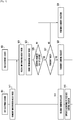
- FIG. 4 is a flow diagram illustrating an operation setup between first and second electronic devices 401 and 402 according to an embodiment.
- the first electronic device 401 may be identical or similar to the electronic device 101 of FIG. 1 or the electronic device 201 of FIG. 2 .
- the second electronic device 402 may be identical or similar to the electronic device 101 of FIG. 1 or the electronic device 201 of FIG. 2 .
- the first electronic device 401 may be an IoT device.
- the second electronic device 402 may be a server or a mobile device.
- the second electronic device 402 may receive an input related to information about operation setup of the first electronic device 401.
- the information about operation setup may include information regarding various operations setups, suchas information about the first operation setup, information about the second operation setup, and/or the like.
- the information about operation setup may be information regarding the operation of at least one of a processor (e.g., the processor 210 of FIG. 2 ), a memory (e.g., the memory 230 of FIG. 2 ), and a motion sensor (e.g., the acceleration sensor 240E of FIG. 2 ) which are included in the first electronic device 401, or information for operating a communication module (e.g., the communication module 220 of FIG. 2 ) in accordance with a predetermined profile and/ or scenario.
- a processor e.g., the processor 210 of FIG. 2
- a memory e.g., the memory 230 of FIG. 2
- a motion sensor e.g., the acceleration sensor 240E of FIG. 2
- operating cycles of a power saving mode, a discontinuous reception (DRX) mode, and an extended discontinuous reception (eDRX) mode of the first electronic device 401 may be varied, and also location measuring cycles of the first electronic device 401 may be varied.
- the second electronic device 402 may previously store or includean application capable of setting or changing the information about operation setup.
- the second electronic device 402 may display an application execution screen suitable for setting or changing the information about operation setup on its display (e.g., the display 260 of FIG. 2 ).
- the second electronic device 402 may display a user interface to be used for setting one or more predetermined profiles and/ or scenarios. Thereby, the user may enter various inputs for setting the information about operation setup.
- the second electronic device 402 may display one or more icons and/or items corresponding to the one or more profiles and/ or scenarios. Also, the second electronic device 402 may receive a user input for selecting the one or more icons and/or items through an input device (e.g., the input device 250 of FIG. 2 ).
- an input device e.g., the input device 250 of FIG. 2 .
- the second electronic device 402 may receive an input for selecting the one or more profiles and/or scenarios.
- the second electronic device 402 may change the operating cycle and the location measuring cycle of the first electronic device 401.
- the second electronic device 402 may change the operating cycles of the power saving mode, the DRX mode, and the eDRX mode of the first electronic device 401 and the location measuring cycle of the first electronic device 401.
- the second electronic device 402 may store the inputted information about the operation setup of the first electronic device 401 in a memory (e.g., the memory 230 of FIG. 2 ).
- the second electronic device 402 may transmit the information about the operation setup of the first electronic device 401 to the first electronic device 401 through a communication module (e.g., the communication module 220 of FIG. 2 ).
- a communication module e.g., the communication module 220 of FIG. 2
- the first electronic device 401 may receive the information about the operation setup of the first electronic device 401 through a communication module (e.g., the communication module 220 of FIG. 2 ).
- a communication module e.g., the communication module 220 of FIG. 2 .
- the first electronic device 401 may store the information about operation setup in a memory (e.g., the memory 230 of FIG. 2 ).
- a processor e.g., the processor 210 of FIG. 2
- the first electronic device 401 may store the information about operation setup in a memory (e.g., the memory 230 of FIG. 2 ).
- the first electronic device 401 may operate in accordance with the information about operation setup.
- the processor e.g., the processor 210 of FIG. 2
- the communication module e.g., the communication module 220 of FIG. 2
- the processor e.g., the processor 210 of FIG. 2
- the communication module e.g., the communication module 220 of FIG. 2
- the processor may be individually or simultaneously operated.
- the communication module (e.g., the communication module 220 of FIG. 2 ) included in the first electronic device 401 and the second electronic device 402 may supportLTE category M1 and LTE category NB-1.
- Each of the first electronic device 401 and the second electronic device 402 may be capable of operating in a power saving mode, a DRX mode, and/or an eDRX mode.
- the power saving mode enables each of the first electronic device 401 and the second electronic device 402 to enter in a sleep state so as to reduce power consumption.
- the processor e.g., the processor 210 of FIG. 2
- the communication module e.g., the communication module 220 of FIG. 2
- the processor may be deactivated or be in sleep mode.
- the DRX mode and the eDRX mode may extend or change the sleep cycle of the communication module (e.g., the communication module 220 of FIG. 2 ) when the communication module is in its sleep state.
- the communication module e.g., the communication module 220 of FIG. 2
- the first electronic device 401 and the second electronic device 402 may support the power saving mode, the DRX mode, and the eDRX mode.
- each of the first and second electronic devices 401 and 402 may transmit a request message containing power saving related parameters suchas an active time during the power saving mode and a DRX value for the eDRX mode, receive an acceptance message containing at least one selection parameter indicating power saving, trigger a timer for activating the selected power saving mechanism, define a usage period of the selected power saving mechanism, and receive a paging signal for changing system information during a broadcast control channel (BCCH) change period.
- BCCH broadcast control channel
- FIG. 5 is a flow diagram illustrating transmission of a control request between first and second electronic devices 401 and 402 according to an embodiment.
- the first electronic device 401 may transmit information about its current mode to the second electronic device 402 through the communication module (e.g., 220 of FIG. 2 ).
- the communication module e.g., 220 of FIG. 2
- the information about its current mode may be information about whether the first electronic device 401 is the power saving mode, the DRX mode, or the eDRX mode.
- the second electronic device 402 may receive the information about the mode of the first electronic device 401 from the first electronic device 401 through the communication module (e.g., 220 of FIG. 2 ).
- the second electronic device 402 may store the received information about the mode of the first electronic device 401 in the memory (e.g., 230 of FIG. 2 ).
- the second electronic device 402 may determine whether there is a control request for the first electronic device 401.
- the second electronic device 402 may continue to perform its current function, which may be unrelated to the operations shown in FIG. 5 , under the control of the processor (e.g., 210 of FIG. 2 ) at operation 531.
- the processor e.g., 210 of FIG. 2
- the second electronic device 402 may perform operation 527 under the control of the processor (e.g., 210 of FIG. 2 ).
- the second electronic device 402 may determine whether the control request for the first electronic device 401 is transmittable to the first electronic device 401.
- the second electronic device 402 may determine, based on the information previously received in operation 521, that the control request for the first electronic device 401 is not transmittable to the first electronic device 401.
- the second electronic device 402 may determine, based on the information received in operation 521, that the control request for the first electronic device 401 is transmittable to the first electronic device 401.
- the second electronic device 402 may determine, based on the stored information about the mode of the first electronic device 401, whether the control request for the first electronic device 401 is transmittable to the first electronic device 401.
- the second electronic device 402 may continueto perform its currentfunctionunder the control of the processor (e.g., 210 of FIG. 2 ) at operation 531.
- the second electronic device 402 may perform operation 529 under the control of the processor (e.g., 210 of FIG. 2 ).
- the second electronic device 402 may transmit the control request for the first electronic device 401 to the first electronic device 401 through the communication module (e.g., 220 of FIG. 2 ).
- the first electronic device 401 may receive the control request for the first electronic device 401 from the second electronic device 402 through the communication module (e.g., 220 of FIG. 2 ).
- the communication module e.g., 220 of FIG. 2
- the first electronic device 401 may control operations thereof in accordance with the received control request for the first electronic device 401.
- FIG. 6 is a flow diagram illustrating a mode change performed at a first electronic device 401, based on information about first operation setup, according to an embodiment.
- the first electronic device 401 may operate in a first mode.
- the first mode may be the DRX mode or the eDRX mode.
- the first electronic device 401 may determine whether a condition for second mode entry is satisfied.
- the second mode may be the power saving mode.
- the first electronic device 401 may return to operation 601 under the control of the processor (e.g., 210 of FIG. 2 ).
- the first electronic device 401 may perform operation 605 under the control of the processor (e.g., 210 of FIG. 2 ).
- the second mode entry condition may be conditions where the motion of the first electronic device 401 is sensed for a certain time period through the motion sensor (e.g., the acceleration sensor 240E of FIG. 2 ) of the first electronic device 401, where the AP information (e.g., Mac address) of Wi-Fi is detected from a certain area (e.g., home of the user), or where an electronic device having a Bluetooth pairing history (e.g., the second electronic device 402) with the first electronic device 401 is connected through Bluetooth to the first electronic device 401.
- the motion sensor e.g., the acceleration sensor 240E of FIG. 2
- the AP information e.g., Mac address
- Wi-Fi e.g., Mac address
- the first electronic device 401 may enter into the second mode. For example, when entering into the second mode, the first electronic device 401 may release Bluetooth connection.
- the first electronic device 401 may determine whether a condition to enter back into the first mode is satisfied.
- the first mode entry condition may be conditions where the motion of the first electronic device 401 is sensed through the motion sensor (e.g., the acceleration sensor 240E of FIG. 2 ), or when the motion sensor (e.g., the acceleration sensor 240E of FIG. 2 ) is booted up at regular intervals.
- the motion sensor e.g., the acceleration sensor 240E of FIG. 2
- the acceleration sensor 240E of FIG. 2 the acceleration sensor 240E of FIG. 2
- the first electronic device 401 may perform operation 601 under the control of the processor (e.g., 210 of FIG. 2 ) and operate again in the first mode.
- the processor e.g., 210 of FIG. 2
- the first electronic device 401 may perform operation 605 under the control of the processor (e.g., 210 of FIG. 2 ) and continue operation in the second mode.
- the processor e.g., 210 of FIG. 2
- the motion sensor (e.g., the acceleration sensor 240E of FIG. 2 ) may be booted up in a certain cycle in accordance with the IoT communication standard of Open Connectivity Foundation (OCF).
- OCF Open Connectivity Foundation
- FIG. 7 is a flow diagram illustrating a mode change performed at a first electronic device 401, based on information about second operation setup, according to an embodiment.
- the first electronic device 401 may operate in a first mode.
- the first mode may be the DRX mode or the eDRX mode.
- the first electronic device 401 may determine whether a condition for second mode entry is satisfied.
- the second mode may be the power saving mode.
- the first electronic device 401 may return to operation 701 under the control of the processor (e.g., 210 of FIG. 2 ).
- the first electronic device 401 may perform operation 705 under the control of the processor (e.g., 210 of FIG. 2 ).
- the second mode entry condition may be conditions where the motion of the first electronic device 401 is sensed for a certain time period through the motion sensor (e.g., the acceleration sensor 240E of FIG. 2 ) of the first electronic device 401, where the AP information (e.g., Mac address) of Wi-Fi is detected from a certain area (e.g., home of the user), or where an electronic device having a Bluetooth pairing history (e.g., the second electronic device 402) with the first electronic device 401 is connected through Bluetooth to the first electronic device 401.
- the motion sensor e.g., the acceleration sensor 240E of FIG. 2
- the AP information e.g., Mac address
- Wi-Fi e.g., Mac address
- the first electronic device 401 may enter into the second mode. For example, when entering into the second mode, the first electronic device 401 may release Bluetooth connection.
- the first electronic device 401 may determine whether a condition to enter back into the first mode is satisfied.
- the first mode entry condition may be conditions where the motion of the first electronic device 401 is sensed through the motion sensor (e.g., the acceleration sensor 240E of FIG. 2 ), or when the motion sensor (e.g., the acceleration sensor 240E of FIG. 2 ) is booted up at regular intervals.
- the motion sensor e.g., the acceleration sensor 240E of FIG. 2
- the acceleration sensor 240E of FIG. 2 the acceleration sensor 240E of FIG. 2
- the first electronic device 401 may perform operation 709 under the control of the processor (e.g., 210 of FIG. 2 ).
- the first electronic device 401 may operate again in the first mode.
- the first electronic device 401 may measure the location thereof.
- the first electronic device 401 may measure the location thereof by identifying at least one of the cell ID, Wi-Fi positioning, and global navigation satellite system (GNSS) positioning of the first electronic device 401.
- GNSS global navigation satellite system
- the first electronic device 401 may determine, based on the measured location thereof, whether the first electronic device 401 is located within at least one predetermined area.
- the at least one predetermined area may be a geo-fence, a communication (e.g., Bluetooth, Wi-Fi, etc.) accessible area, and the like.
- a communication e.g., Bluetooth, Wi-Fi, etc.
- the first electronic device 401 may perform operation 715 under the control of the processor (e.g., 210 of FIG. 2 ).
- the first electronic device 401 may return to operation 709 under the control of the processor (e.g., 210 of FIG. 2 ).
- the first electronic device 401 may change the operating cycle of the first mode and/or the location measuring cycle of the first electronic device 401.
- the cycle(s) changed at operation 715 may be varied depending on the at least one predetermined area.
- the operating cycle of the first mode and/or the location measuring cycle of the first electronic device 401 changed with respect to the first area may be different from the operating cycle of the first mode and/or the location measuring cycle of the first electronic device 401 changed with respect to the second area.
- Changing the operating cycle of the first mode at operation 715 may include increasing the operating cycle of the first mode used at operation 701 or 709.
- the operating cycle of the first mode used at operation 701 or 709 may be 2.56 seconds
- the operating cycle of the first mode changed at operation 715 may be 10.24 seconds.
- the operating cycle of the first mode used at operation 701 or 709 may be referred to as the first operating cycle, and the operating cycle of the first mode changed at operation 715 may be referred to as the second operating cycle.
- the second operating cycle may be greater than the first operating cycle.
- Changing the location measuring cycle of the first electronic device 401 at operation 715 may include increasing the location measuring cycle of the first electronic device 401 used at operation 711.
- the location measuring cycle used at operation 711 may be referred to as the first measuring cycle, and the location measuring cycle changed at operation 715 may be referred to as the second measuring cycle.
- the second measuring cycle may be greater than the first measuring cycle.
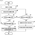
- FIG. 8 is a flow diagram illustrating a mode change performed at a first electronic device 401, based on information about third operation setup, according to an embodiment.
- the first electronic device 401 may operate in a first mode.
- the first mode may be the DRX mode or the eDRX mode.
- the first electronic device 401 may determine whether a condition for second mode entry is satisfied.
- the second mode may be the power saving mode.
- the first electronic device 401 may return to operation 801 under the control of the processor (e.g., 210 of FIG. 2 ).
- the first electronic device 401 may perform operation 805 under the control of the processor (e.g., 210 of FIG. 2 ).
- the second mode entry condition may be condition where the motion of the first electronic device 401 is sensed for a certain time through the motion sensor (e.g., the acceleration sensor 240E of FIG. 2 ) of the first electronic device 401, where the AP information (e.g., Mac address) of Wi-Fi is detected from a certain area (e.g., home of the user), or where an electronic device having a Bluetooth pairing history (e.g., the second electronic device 402) with the first electronic device 401 is connected through Bluetooth to the first electronic device 401.
- the motion sensor e.g., the acceleration sensor 240E of FIG. 2
- the AP information e.g., Mac address
- Wi-Fi e.g., Mac address
- an electronic device having a Bluetooth pairing history e.g., the second electronic device 402
- the first electronic device 401 may enter into the second mode. For example, when entering into the second mode, the first electronic device 401 may release Bluetooth connection.
- the first electronic device 401 may determine whether a condition to enter back into the first mode is satisfied.
- the first mode entry condition may be conditions where the motion of the first electronic device 401 is sensed through the motion sensor (e.g., the acceleration sensor 240E of FIG. 2 ), or when the motion sensor (e.g., the acceleration sensor 240E of FIG. 2 ) is booted up at regular intervals.
- the motion sensor e.g., the acceleration sensor 240E of FIG. 2
- the acceleration sensor 240E of FIG. 2 the acceleration sensor 240E of FIG. 2
- the first electronic device 401 may perform operation 809 under the control of the processor (e.g., 210 of FIG. 2 ).
- the first electronic device 401 may operate again in the first mode.
- the first electronic device 401 may measure the location thereof.
- the first electronic device 401 may measure the location thereof by identifying at least one of the cell ID, Wi-Fi positioning, and GNSS positioning of the first electronic device 401.
- the first electronic device 401 may determine, based on the measured location thereof, whether the first electronic device 401 is located within at least one predetermined area.
- the at least one predetermined area may be a geo-fence, a communication (e.g., Bluetooth, Wi-Fi, etc.) accessible area, and the like.
- a communication e.g., Bluetooth, Wi-Fi, etc.
- the first electronic device 401 may perform operation 815 under the control of the processor (e.g., 210 of FIG. 2 ).
- the first electronic device 401 may return to operation 809 under the control of the processor (e.g., 210 of FIG. 2 ).
- the first electronic device 401 may change the operating cycle of the first mode and/or the location measuring cycle of the first electronic device 401.
- the cycle(s) changed at operation 815 may be varied depending on the at least one predetermined area.
- the operating cycle of the first mode and/or the location measuring cycle of the first electronic device 401 changed with respect to the first area may be different from the operating cycle of the first mode and/or the location measuring cycle of the first electronic device 401 changed with respect to the second area.
- Changing the operating cycle of the first mode at operation 815 may include increasing the operating cycle of the first mode used at operation 801 or 809.
- the operating cycle of the first mode used at operation 801 or 809 may be 2.56 seconds
- the operating cycle of the first mode changed at operation 815 may be 10.24 seconds.
- the operating cycle of the first mode used at operation 801 or 809 may be referred to as the first operating cycle, and the operating cycle of the first mode changed at operation 815 may be referred to as the second operating cycle.
- the second operating cycle may be greater than the first operating cycle.
- Changing the location measuring cycle of the first electronic device 401 at operation 815 may include increasing the location measuring cycle of the first electronic device 401 used at operation 811.
- the location measuring cycle used at operation 811 may be referred to as the first measuring cycle, and the location measuring cycle changed at operation 815 may be referred to as the second measuring cycle.
- the second measuring cycle may be greater than the first measuring cycle.
- the first electronic device 401 may determine whether a motion thereof is detected through the motion sensor (e.g., the acceleration sensor 240E of FIG. 2 ).
- the first electronic device 401 may perform operation 817 again.
- the motion sensor e.g., the acceleration sensor 240E of FIG. 2
- the first electronic device 401 may perform operation 819.
- the first electronic device 401 may further change the operating cycle of the first mode and/or the location measuring cycle of the first electronic device 401.
- Further changing the operating cycle of the first mode at operation 819 may include further increasing the operating cycle of the first mode changed at operation 815.
- the operating cycle of the first mode changed at operation 815 may be referred to as the second operating cycle, and the operating cycle of the first mode further changed at operation 819 may be referred to as the third operating cycle.
- the third operating cycle may be greater than the second operating cycle.
- Further changing the location measuring cycle of the first electronic device 401 at operation 819 may include further increasing the location measuring cycle of the first electronic device 401 changed at operation 815.
- the location measuring cycle changed at operation 815 may be referred to as the second measuring cycle, and the location measuring cycle further changed at operation 819 may be referred to as the third measuring cycle.
- the third measuring cycle may be greater than the second measuring cycle.
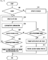
- FIG. 9 is a flow diagram illustrating a mode change performed at a first electronic device 401, based on information about fourth operation setup, according to an embodiment.
- the first electronic device 401 may operate in a first mode.
- the first mode may be the DRX mode or the eDRX mode.
- the first electronic device 401 may scan Bluetooth communication by controlling the communication module (e.g., 220 of FIG. 2 ).
- the first electronic device 401 may determine, based on the result of the Bluetooth scanning operation, whether the first electronic device 401 is in a Bluetooth pairing state.
- the first electronic device 401 may perform operation 907.
- the first electronic device 401 may perform operation 911.
- the first electronic device 401 may determine, based on the measured location thereof, whether the first electronic device 401 is located within at least one predetermined area.
- the first electronic device 401 may perform operation 909 under the control of the processor (e.g., 210 of FIG. 2 ).
- the first electronic device 401 may return to operation 901 under the control of the processor (e.g., 210 of FIG. 2 ).
- the at least one predetermined area may be a geo-fence, a communication (e.g., Bluetooth, Wi-Fi, etc.) accessible area, and the like.
- a communication e.g., Bluetooth, Wi-Fi, etc.
- the first electronic device 401 may measure the location thereof by identifying at least one of the cell ID, Wi-Fi positioning, and GNSS positioning of the first electronic device 401.
- the first electronic device 401 may change the operating cycle of the first mode and/or the location measuring cycle of the first electronic device 401.
- the cycle(s) changed at operation 909 may be varied depending on the at least one predetermined area.
- the operating cycle of the first mode and/or the location measuring cycle of the first electronic device 401 changed with respect to the first area may be different from the operating cycle of the first mode and/or the location measuring cycle of the first electronic device 401 changed with respect to the second area.
- Changing the operating cycle of the first mode at operation 909 may include increasing the operating cycle of the first mode used at operation 901.
- the operating cycle of the first mode used at operation 901 may be 2.56 seconds
- the operating cycle of the first mode changed at operation 909 may be 10.24 seconds.
- the operating cycle of the first mode used at operation 901 may be referred to as the first operating cycle, and the operating cycle of the first mode changed at operation 909 may be referred to as the second operating cycle.
- the second operating cycle may be greater than the first operating cycle.
- Changing the location measuring cycle of the first electronic device 401 at operation 909 may include increasing the location measuring cycle of the first electronic device 401 used at operation 907.
- the location measuring cycle used at operation 907 or 911 may be referred to as the first measuring cycle, and the location measuring cycle changed at operation 909 may be referred to as the second measuring cycle.
- the second measuring cycle may be greater than the first measuring cycle.
- the first electronic device 401 may determine, based on the measured location thereof, whether the first electronic device 401 is located within at least one predetermined area.
- the first electronic device 401 may return to operation 903 under the control of the processor (e.g., 210 of FIG. 2 ).
- the first electronic device 401 may perform operation 913 under the control of the processor (e.g., 210 of FIG. 2 ).
- the first electronic device 401 may transmit a notification to the second electronic device 402.
- the notification transmitted to the second electronic device 402 may be a notification of loss and may be in the form of an email, a message, an instant message, or any other suitablemessage.
- the first electronic device 401 may perform a location tracking operation in real time or in response to a user's request.
- the first electronic device 401 may track the location thereof by identifying at least one of the cell ID, Wi-Fi positioning, and GNSS positioning of the first electronic device 401.
- FIG. 10 is a flow diagram illustrating a mode change performed at a first electronic device 401, based on information about fifth operation setup, according to an embodiment.
- the first electronic device 401 may determine whether the user is wearing the first electronic device 401.
- the first electronic device 401 may determine that the user is wearing the first electronic device 401. If no motion of the first electronic device 401 is detected for a certain time period, the first electronic device 401 may determine that the user is not wearing the first electronic device 401.
- the first electronic device 401 may determine that the user is wearing the first electronic device 401. Conversely, if no heartbeat is detected for a certain time period, the first electronic device 401 may determine that the user is not wearing the first electronic device 401.
- HRM heart rate module
- the first electronic device 401 may determine whether the user is wearing the first electronic device 401 through the proximity sensor (e.g., 240G of FIG. 2 ). In other words, the first electronic device 401 may detect the user is proximate to the first electronic device 401.
- the proximity sensor e.g., 240G of FIG. 2
- the first electronic device 401 may perform operation 1003.
- the first electronic device 401 may perform operation 1013.
- the first electronic device 401 may operate in a second mode.
- the second mode may be the power saving mode.
- the first electronic device 401 may operate in a first mode.
- the first mode may be the DRX mode or the eDRX mode.
- the first electronic device 401 may scan Bluetooth communication by controlling the communication module (e.g., 220 of FIG. 2 ).
- the first electronic device 401 may identify a Bluetooth pairing state, based on the result of the Bluetooth scanning. That is, at operation 1007, under the control of the processor (e.g., 210 of FIG. 2 ), the first electronic device 401 may determine, based on the result of the Bluetooth scanning, whether the first electronic device 401 is in the Bluetooth pairing state.
- the first electronic device 401 may perform operation 1009.
- the first electronic device 401 may perform operation 1015.
- the first electronic device 401 may determine, based on the measured location thereof, whether the first electronic device 401 is located within at least one predetermined area.
- the first electronic device 401 may perform operation 1011 under the control of the processor (e.g., 210 of FIG. 2 ).
- the first electronic device 401 may return to operation 1003 under the control of the processor (e.g., 210 of FIG. 2 ).
- the at least one predetermined area may be a geo-fence, a communication (e.g., Bluetooth, Wi-Fi, etc.) accessible area, and the like.
- a communication e.g., Bluetooth, Wi-Fi, etc.
- the first electronic device 401 may measure the location thereof by identifying at least one of the cell ID, Wi-Fi positioning, and GNSS positioning of the first electronic device 401.
- the first electronic device 401 may change the operating cycle of the first mode and/or the location measuring cycle of the first electronic device 401.
- the cycle(s) changed at operation 1011 may be varied depending on the at least one predetermined area.
- the operating cycle of the first mode and/or the location measuring cycle of the first electronic device 401 changed with respect to the first area may be different from the operating cycle of the first mode and/or the location measuring cycle of the first electronic device 401 changed with respect to the second area.
- Changing the operating cycle of the first mode at operation 1011 may include increasing the operating cycle of the first mode used at operation 1003.
- the operating cycle of the first mode used at operation 1003 may be 2.56 seconds
- the operating cycle of the first mode changed at operation 1011 may be 10.24 seconds.
- the operating cycle of the first mode used at operation 1003 may be referred to as the first operating cycle, and the operating cycle of the first mode changed at operation 1011 may be referred to as the second operating cycle.
- the second operating cycle may be greater than the first operating cycle.
- Changing the location measuring cycle of the first electronic device 401 at operation 1011 may include increasing the location measuring cycle of the first electronic device 401 used at operation 1009.
- the location measuring cycle used at operation 1009 or 1015 may be referred to as the first measuring cycle, and the location measuring cycle changed at operation 1011 may be referred to as the second measuring cycle.
- the second measuring cycle may be greater than the first measuring cycle.
- the first electronic device 401 may determine, based on the measured location thereof, whether the first electronic device 401 is located within at least one predetermined area.
- the first electronic device 401 may return to operation 1005 under the control of the processor (e.g., 210 of FIG. 2 ).
- the first electronic device 401 may perform operation 1017 under the control of the processor (e.g., 210 of FIG. 2 ).
- the first electronic device 401 may transmit a notification to the second electronic device 402.
- the notification transmitted to the second electronic device 402 may be a notification of loss and may be in the form of an email, a message, an instant message, or any other suitable message.
- the first electronic device 401 may perform a location tracking operation in real time or in response to a user's request.
- the first electronic device 401 may track the location thereof by identifying at least one of the cell ID, Wi-Fi positioning, and GNSS positioning of the first electronic device 401.
- FIG. 11 is a flow diagram illustrating a mode change performed at a first electronic device 401, based on information about sixth operation setup, according to an embodiments.
- the first electronic device 401 may activate its motion sensor (e.g., the acceleration sensor 240E of FIG. 2 ).
- the first electronic device 401 may operate in a second mode.
- the second mode may be the power saving mode.
- the first electronic device 401 may determine whether a motion thereof is detected through the motion sensor (e.g., the acceleration sensor 240E of FIG. 2 ).
- the first electronic device 401 may return to operation 1103.
- the first electronic device 401 may perform operation 1107.
- the first electronic device 401 may scan Bluetooth communication by controlling the communication module (e.g., 220 of FIG. 2 ).
- the first electronic device 401 may determine, based on the result of the Bluetooth scanning, whether an electronic device having a Bluetooth communication pairing history with the first electronic device 401 is within Bluetooth range.
- the first electronic device 401 may perform operation 1111 under the control of the processor (e.g., 210 of FIG. 2 ).
- the first electronic device 401 may perform operation 1117 under the control of the processor (e.g., 210 of FIG. 2 ).
- the first electronic device 401 may perform Bluetooth communication pairing with the detected electronic device by controlling the communication module (e.g., 220 of FIG. 2 ).
- the first electronic device 401 may deactivate the motion sensor (e.g., the acceleration sensor 240E of FIG. 2 ).
- the first electronic device 401 may determine whether the Bluetooth communication pairing is released.
- the first electronic device 401 may return to operation 1103 under the control of the processor (e.g., 210 of FIG. 2 ).
- the first electronic device 401 may perform operation 1115 again under the control of the processor (e.g., 210 of FIG. 2 ).
- the first electronic device 401 may transmit a notification to the second electronic device 402.
- the notification transmitted to the second electronic device 402 may be a notification of loss and may be in the form of an email, a message, an instant message, or any other suitablemessage.
- the first electronic device 401 may perform a location tracking operation in real time or in response to a user's request.
- the first electronic device 401 may track the location thereof by identifying at least one of the cell ID, Wi-Fi positioning, and GNSS positioning of the first electronic device 401.
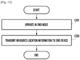
- FIG. 12 is a flow diagram illustrating a mode change performed at a first electronic device 401, based on information about seventh operation setup, according to an embodiment.
- the first electronic device 401 may operate in a second mode.
- the second mode may be the power saving mode.
- the first electronic device 401 may measure the location thereof and then transmit information about the measured location to the second electronic device 402 through the communication module (e.g., 220 of FIG. 2 ).
- the communication module e.g., 220 of FIG. 2
- the first electronic device 401 may measure the location thereof by identifying at least one of the cell ID, Wi-Fi positioning, and GNSS positioning of the first electronic device 401.
- module usedin this disclosure may refer to a certain unit that includes one of hardware, software, and firmware, or any combination thereof.
- the module may be interchangeably used with unit, logic, logical block, component, or circuit, for example.
- the module may be the entire unit, or part thereof, which performs one or more particular functions.
- the module may be formed mechanically or electronically.
- the module disclosed herein may include at least one of application-specific integrated circuit (ASIC) chip, field-programmable gate arrays (FPGAs), and programmable-logic device, which have been known or are to be developed.
- ASIC application-specific integrated circuit
- FPGAs field-programmable gate arrays
- programmable-logic device which have been known or are to be developed.
- At least part of the device (e.g., modules or functions thereof) or method (e.g., operations) may be implemented as instructions stored, e.g., in the form of a program module, in a computer-readable storage medium.
- the processor may perform a particular functioncorresponding to those instructions.
- the non-transitory computer-readable recording medium may include magnetic media suchas a hard disk, a floppy disk, and a magnetic tape, optical media suchas a Compact Disc Read Only Memory (CD-ROM) and a Digital Versatile Disc (DVD), magneto-optical media suchas a floptical disk, and hardware devices specially configured to store and perform a program instruction.
- the program instructions may include high class language codes, which can be executed in a computer by using an interpreter, as well as machine codes made by a compiler.
- Certain aspects of the above-described embodiments of the present disclosure can be implemented in hardware, firmware or via the execution of software or computer code that can be stored in a recording medium suchas a CD ROM, a Digital Versatile Disc (DVD), a magnetic tape, a RAM, a floppy disk, a hard disk, or a magneto-optical disk or computer code downloaded over a network originally stored on a remote recording medium or a non-transitory machine readable medium and to be stored on a local recording medium, so that the methods described herein can be rendered via such-software that is stored on the recording medium using a general purposecomputer, or a special processor or in programmable or dedicated hardware, suchas an ASIC or FPGA.
- a recording medium suchas a CD ROM, a Digital Versatile Disc (DVD), a magnetic tape, a RAM, a floppy disk, a hard disk, or a magneto-optical disk or computer code downloaded over a network originally stored on a remote recording medium
- the computer, the processor, microprocessor controller or the programmable hardware include memory components, e.g., RAM, ROM, Flash, etc. that may store or receive software or computer code that when accessed and executed by the computer, processor or hardware implement the processing methods described herein.
- memory components e.g., RAM, ROM, Flash, etc. that may store or receive software or computer code that when accessed and executed by the computer, processor or hardware implement the processing methods described herein.
Landscapes
- Engineering & Computer Science (AREA)
- Computer Networks & Wireless Communication (AREA)
- Signal Processing (AREA)
- Health & Medical Sciences (AREA)
- Computing Systems (AREA)
- General Health & Medical Sciences (AREA)
- Medical Informatics (AREA)
- Telephone Function (AREA)
Claims (14)
- Kommunikationssteuerungsverfahren einer elektronischen Vorrichtung, wobei das Verfahren Folgendes umfasst:Betreiben (901, 1003) der elektronischen Vorrichtung in einem ersten Modus mit einem ersten Arbeitszyklus;Messen eines Standorts der elektronischen Vorrichtung;basierend auf einem Ergebnis des Messens des Standorts der elektronischen Vorrichtung und während eines ersten Messzyklus, Bestimmen (907, 911, 1009, 1015), ob sich die elektronische Vorrichtung innerhalb des mindestens einen vorbestimmten Bereichs befindet;Ändern (909, 1011) des ersten Arbeitszyklus des ersten Modus oder des ersten Messzyklus der elektronischen Vorrichtung, wenn sich die elektronische Vorrichtung innerhalb des mindestens einen vorbestimmten Bereichs befindet;wenn sich die elektronische Vorrichtung nicht innerhalb des mindestens einen vorbestimmten Bereichs befindet, Übertragen (913, 1017) einer Verlustmeldung an eine zweite elektronische Vorrichtung undAusführen (915, 1019) einer Standortverfolgungsoperation in Echtzeit oder als Antwort auf eine Benutzeranforderung,wobei der mindestens eine vorbestimmte Bereich ein Geofence und/oder ein für die Kommunikation zugänglicher Bereich ist.
- Verfahren nach Anspruch 1, wobei das Ändern (909, 1011) des ersten Arbeitszyklus des ersten Modus oder des ersten Messzyklus der elektronischen Vorrichtung Folgendes umfasst:Ändern (909, 1011) des ersten Arbeitszyklus des ersten Modus von dem ersten Arbeitszyklus in einen zweiten Arbeitszyklus; undÄndern (909, 1011) des ersten Messzyklus der elektronischen Vorrichtung von dem ersten Messzyklus in einen zweiten Messzykluswobei der zweite Arbeitszyklus größer als der erste Arbeitszyklus ist, undwobei der zweite Messzyklus größer als der erste Messzyklus ist.
- Verfahren nach Anspruch 1, welches ferner Folgendes umfasst:
Fortsetzen des Betreibens (901, 1003) in dem ersten Modus mit dem ersten Arbeitszyklus, wenn sich die elektronische Vorrichtung nicht innerhalb des mindestens einen vorbestimmten Bereichs befindet. - Verfahren nach Anspruch 1, welches ferner Folgendes umfasst:Bestimmen, ob eine Bedingung für den Eintritt in den zweiten Modus erfüllt wird; undBetreiben (1013) der elektronischen Vorrichtung in einem zweiten Modus, wenn die Bedingung für den Eintritt in den zweiten Modus erfüllt wird,wobei der erste Modus ein diskontinuierlicher Empfangs(DRX)-Modus und/oder ein erweiterter diskontinuierlicher Empfangs(eDRX)-Modus ist,wobei der zweite Modus ein Energiesparmodus ist,wobei die Bedingung für die Bedingung für den Eintritt in den zweiten Modus eine erste Bedingung enthält, bei der eine Bewegung der elektronischen Vorrichtung für einen spezifischen Zeitraum durch einen Bewegungssensor der elektronischen Vorrichtung erfasst wird, eine zweite Bedingung, bei der Zugangspunkt(AP)-Informationen des Wi-Fi aus einem spezifischen Bereich erkannt werden, und/oder eine dritte Bedingung, bei der die zweite elektronische Vorrichtung, die einen Bluetooth-Kopplungsverlauf mit der elektronischen Vorrichtung hat, über Bluetooth mit der elektronischen Vorrichtung verbunden istwelches ferner Folgendes umfasst:Bestimmen, ob eine Bedingung für den Eintritt in den ersten Modus erfüllt wird; underneutes Betreiben der elektronischen Vorrichtung in dem ersten Modus mit dem ersten Arbeitszyklus, wenn die Bedingung für den Eintritt in den ersten Modus erfüllt wird,wobei die Bedingung für den Eintritt in den ersten Modus eine vierte Bedingung enthält, bei der eine andere Bewegung der elektronischen Vorrichtung durch den Bewegungssensor erfasst wird, und/oder eine fünfte Bedingung, bei der der Bewegungssensor in regelmäßigen Abständen hochgefahren wird.
- Verfahren nach Anspruch 1, welches ferner Folgendes umfasst:Bestimmen, ob eine Bewegung der elektronischen Vorrichtung durch einen Bewegungssensor der elektronischen Vorrichtung erkannt wird; undweiteres Ändern des ersten Arbeitszyklus des ersten Modus oder des ersten Messzyklus der elektronischen Vorrichtung, wenn die Bewegung der elektronischen Vorrichtung für einen spezifischen Zeitraum nicht durch den Bewegungssensor erkannt wird.
- Verfahren nach Anspruch 5, wobei das weitere Ändern des ersten Arbeitszyklus des ersten Modus oder des ersten Messzyklus der elektronischen Vorrichtung Folgendes umfasst:Ändern des ersten Arbeitszyklus des ersten Modus in einen dritten Arbeitszyklus; undÄndern des ersten Messzyklus der elektronischen Vorrichtung in einen dritten Messzykluswobei der dritte Arbeitszyklus größer als der erste Arbeitszyklus ist, undwobei der dritte Messzyklus größer als der erste Messzyklus ist.
- Verfahren nach Anspruch 4,
wobei der erste Modus einem Kommunikationsmodul der elektronischen Vorrichtung ermöglicht, aktiv oder inaktiv zu sein, und
wobei der zweite Modus einem Prozessor der elektronischen Vorrichtung und dem Kommunikationsmodul ermöglicht, in einem Ruhezustand zu sein. - Elektronische Vorrichtung (101, 201, 401), welche Folgendes umfasst:einen Bewegungssensor (240E);ein Kommunikationsmodul (220);einen Prozessor (210); undeinen Speicher (230),wobei der Speicher (230) Anweisungen speichert, die, wenn sie von dem Prozessor (210) ausgeführt werden, den Prozessor (210) veranlassen zum:Betreiben der elektronischen Vorrichtung (101, 201, 401) in einem ersten Modus mit einem ersten Arbeitszyklus,Messen eines Standorts der elektronischen Vorrichtung (101, 201, 401) durch das Kommunikationsmodul (220),basierend auf einem Ergebnis des Messens des Standorts der elektronischen Vorrichtung (101, 201, 401) und während eines ersten Messzyklus, Bestimmen, ob sich die elektronische Vorrichtung (101, 201, 401) innerhalb des mindestens einen vorbestimmten Bereichs befindet, undÄndern des ersten Arbeitszyklus des ersten Modus oder des ersten Messzyklus der elektronischen Vorrichtung (101, 201, 401), wenn sich die elektronische Vorrichtung (101, 201, 401) innerhalb des mindestens einen vorbestimmten Bereichs befindet, und wenn sich die elektronische Vorrichtung nicht innerhalb des mindestens einen vorbestimmten Bereichs befindet, Veranlassen des Prozessors, über das Kommunikationsmodul eine Verlustmeldung an eine zweite elektronische Vorrichtung zu übertragen und eine Standortverfolgungsoperation in Echtzeit oder als Antwort auf eine Benutzeranforderung auszuführen,wobei der mindestens eine vorbestimmte Bereich ein Geofence und/oder ein für die Kommunikation zugänglicher Bereich ist.
- Elektronische Vorrichtung (101, 201, 401) nach Anspruch 8, wobei der Speicher (230) ferner Anweisungen speichert, die, wenn sie von dem Prozessor (210) ausgeführt werden, den Prozessor (210) veranlassen zum:Ändern des ersten Arbeitszyklus des ersten Modus von dem ersten Arbeitszyklus in einen zweiten Arbeitszyklus, undÄndern des ersten Messzyklus der elektronischen Vorrichtung von dem ersten Messzyklus in einen zweiten Messzyklus,wobei der zweite Arbeitszyklus größer als der erste Arbeitszyklus ist, undwobei der zweite Messzyklus größer als der erste Messzyklus ist.
- Elektronische Vorrichtung (101, 201, 401) nach Anspruch 11, wobei der Speicher (230) ferner Anweisungen speichert, die, wenn sie von dem Prozessor (210) ausgeführt werden, den Prozessor (210) veranlassen zum:Bestimmen, ob eine Bedingung für den Eintritt in den zweiten Modus erfüllt wird, undBetreiben der elektronischen Vorrichtung (101, 201, 401) in einem zweiten Modus, wenn die Bedingung für den Eintritt in den zweiten Modus erfüllt wird, undwobei die Bedingung für den Eintritt in den zweiten Modus eine erste Bedingung enthält, bei der eine Bewegung der elektronischen Vorrichtung für einen spezifischen Zeitraum durch den Bewegungssensor erfasst wird, eine zweite Bedingung, bei der Zugangspunkt(AP)-Informationen des Wi-Fi aus einem spezifischen Bereich erkannt werden, und/oder eine dritte Bedingung, bei der die zweite elektronische Vorrichtung (102, 201, 402), die einen Bluetooth-Kopplungsverlauf mit der elektronischen Vorrichtung (101, 201, 401) hat, über Bluetooth mit der elektronischen Vorrichtung verbunden ist,wobei der Speicher ferner Anweisungen speichert, die, wenn sie von dem Prozessor (210) ausgeführt werden, den Prozessor (210) veranlassen zum:Bestimmen, ob eine Bedingung für den Eintritt in den ersten Modus erfüllt wird, underneutes Betreiben der elektronischen Vorrichtung (101, 201, 401) in dem ersten Modus mit dem ersten Arbeitszyklus, wenn die Bedingung für den Eintritt in den ersten Modus erfüllt wird, undwobei die Bedingung für den Eintritt in den ersten Modus eine vierte Bedingung enthält, bei der eine Bewegung der elektronischen Vorrichtung (101, 201, 401) durch den Bewegungssensor erfasst wird, und/oder eine fünfte Bedingung, bei der der Bewegungssensor in regelmäßigen Abständen hochgefahren wird.
- Elektronische Vorrichtung (101, 201, 401) nach Anspruch 8, wobei der Speicher (230) ferner Anweisungen speichert, die, wenn sie von dem Prozessor (210) ausgeführt werden, den Prozessor (210) veranlassen zum:Bestimmen, ob eine Bewegung der elektronischen Vorrichtung (101, 201, 401) durch den Bewegungssensor (240E) erkannt wird, undweiteres Ändern des ersten Arbeitszyklus des ersten Modus oder des ersten Messzyklus der elektronischen Vorrichtung (101, 201, 401), wenn die Bewegung der elektronischen Vorrichtung (101, 201, 401) für einen spezifischen Zeitraum nicht durch den Bewegungssensor (240E) erkannt wird.
- Elektronische Vorrichtung (101, 201, 401) nach Anspruch 10, wobei der erste Modus ein diskontinuierlicher Empfangs(DRX)-Modus und/oder ein erweiterter diskontinuierlicher Empfangs(eDRX)-Modus ist,
wobei der zweite Modus ein Energiesparmodus ist,
wobei der erste Modus einem Kommunikationsmodul (220) der elektronischen Vorrichtung (101, 201, 401) ermöglicht, aktiv oder inaktiv zu sein, und
wobei der zweite Modus einem Prozessor (210) der elektronischen Vorrichtung (101, 201, 401) und dem Kommunikationsmodul (220) ermöglicht, in einem Ruhezustand zu sein. - Elektronische Vorrichtung (101, 201, 401) nach Anspruch 8, wobei der Speicher (230) ferner Anweisungen speichert, die, wenn sie von dem Prozessor (210) ausgeführt werden, den Prozessor (210) veranlassen zum:während des Betreibens der elektronischen Vorrichtung (101, 201, 401) in dem ersten Modus mit dem ersten Arbeitszyklus, Scannen der Bluetooth-Kommunikation,Bestimmen, basierend auf einem Ergebnis des Scannens, ob sich die elektronische Vorrichtung (101, 201, 401) in einem Bluetooth-Kopplungszustand befindet,Ändern des ersten Arbeitszyklus des ersten Modus und des ersten Messzyklus der elektronischen Vorrichtung (101, 201, 401), wenn sich die elektronische Vorrichtung (101, 201, 401) in dem Bluetooth-Kopplungszustand befindet.
- Elektronische Vorrichtung (101, 201, 401) nach Anspruch 13, wobei der Speicher (230) ferner Anweisungen speichert, die, wenn sie von dem Prozessor (210) ausgeführt werden, den Prozessor (210) veranlassen, weiterhin die elektronische Vorrichtung (101, 201, 401) in dem ersten Modus mit dem ersten Arbeitszyklus zu betreiben, wenn sich die elektronische Vorrichtung (101, 201, 401) nicht innerhalb des mindestens einen vorbestimmten Bereichs befindet, und
wenn sie von dem Prozessor (210) ausgeführt werden, den Prozessor (210) veranlassen zu bestimmen, ob sich die elektronische Vorrichtung (101, 201, 401) innerhalb des mindestens einen vorbestimmten Bereichs befindet, wenn sich die elektronische Vorrichtung (101, 201, 401) nicht in dem Bluetooth-Kopplungszustand befindet.
Applications Claiming Priority (2)
| Application Number | Priority Date | Filing Date | Title |
|---|---|---|---|
| KR1020170025035A KR102665991B1 (ko) | 2017-02-24 | 2017-02-24 | 전자 장치 및 전자 장치의 통신 제어 방법 |
| PCT/KR2018/002255 WO2018155953A1 (en) | 2017-02-24 | 2018-02-23 | Electronic device and method for controlling communication thereof |
Publications (3)
| Publication Number | Publication Date |
|---|---|
| EP3569003A1 EP3569003A1 (de) | 2019-11-20 |
| EP3569003A4 EP3569003A4 (de) | 2019-12-04 |
| EP3569003B1 true EP3569003B1 (de) | 2021-04-07 |
Family
ID=63245405
Family Applications (1)
| Application Number | Title | Priority Date | Filing Date |
|---|---|---|---|
| EP18757188.0A Active EP3569003B1 (de) | 2017-02-24 | 2018-02-23 | Elektronische vorrichtung und verfahren zur steuerung der kommunikation davon |
Country Status (4)
| Country | Link |
|---|---|
| US (1) | US10863435B2 (de) |
| EP (1) | EP3569003B1 (de) |
| KR (1) | KR102665991B1 (de) |
| WO (1) | WO2018155953A1 (de) |
Families Citing this family (6)
| Publication number | Priority date | Publication date | Assignee | Title |
|---|---|---|---|---|
| KR102785619B1 (ko) * | 2019-03-19 | 2025-03-26 | 삼성전자 주식회사 | 무선 통신 채널을 통한 주기적인 측위 통신을 제공하는 전자 장치 |
| CN111651030B (zh) * | 2020-06-01 | 2022-04-22 | 惠州Tcl移动通信有限公司 | 传感器检测方法、装置、存储介质及移动终端 |
| US12574997B2 (en) * | 2020-12-25 | 2026-03-10 | Beijing Xiaomi Mobile Software Co., Ltd. | Terminal control method, information processing method, communication device, and storage medium |
| KR20220117645A (ko) * | 2021-02-17 | 2022-08-24 | 삼성전자주식회사 | 외부 전자 장치의 위치를 결정하는 전자 장치 및 전자 장치의 동작 방법 |
| KR20230018825A (ko) | 2021-07-30 | 2023-02-07 | 삼성전자주식회사 | 지오펜스를 이용하는 전자 장치 및 동작 방법 |
| KR20230046531A (ko) * | 2021-09-30 | 2023-04-06 | 삼성전자주식회사 | 전자 장치 및 이의 제어 방법 |
Family Cites Families (16)
| Publication number | Priority date | Publication date | Assignee | Title |
|---|---|---|---|---|
| US7209865B2 (en) | 2004-12-29 | 2007-04-24 | Fueling Technologies, Inc. | Method and system for remotely processing volumetric data |
| US7427952B2 (en) | 2005-04-08 | 2008-09-23 | Trueposition, Inc. | Augmentation of commercial wireless location system (WLS) with moving and/or airborne sensors for enhanced location accuracy and use of real-time overhead imagery for identification of wireless device locations |
| KR101184610B1 (ko) | 2006-11-30 | 2012-09-21 | 삼성전자주식회사 | 위치 정보를 이용하는 전력 절감 장치 및 방법 |
| MX2012002088A (es) | 2009-08-17 | 2012-04-10 | Deal Magic Inc | Monitoreo contextualmente alerta de activos. |
| US9301225B2 (en) | 2010-01-08 | 2016-03-29 | Interdigital Patent Holdings, Inc. | Managing power consumption in base stations and remote access points |
| KR101645461B1 (ko) * | 2010-01-12 | 2016-08-12 | 삼성전자주식회사 | 휴대용 단말기에서 근거리 무선 네트워크 자동 연결 방법 및 장치 |
| EP3171628A1 (de) * | 2010-04-02 | 2017-05-24 | Interdigital Patent Holdings, Inc. | Zustände und verfahren mit geringer mobilität |
| WO2013035984A1 (en) * | 2011-09-08 | 2013-03-14 | Lg Electronics Inc. | Method for operation based on switching discontinuous reception state in wireless communication system and apparatus for the same |
| US8805360B2 (en) | 2012-02-14 | 2014-08-12 | Apple Inc. | Wi-Fi process |
| US9456419B2 (en) * | 2012-07-12 | 2016-09-27 | Lg Electronics Inc. | Method and apparatus for applying a discontinuous reception (DRX) cycle in a wireless communication system |
| KR101997771B1 (ko) * | 2013-04-08 | 2019-07-08 | 삼성전자주식회사 | 저 전력으로 지오 펜스 서비스를 제공받는 전자 장치 및 방법 |
| KR102367356B1 (ko) * | 2014-12-09 | 2022-02-25 | 삼성전자주식회사 | 전자 장치의 소모 전류 제어 |
| WO2016137475A1 (en) | 2015-02-26 | 2016-09-01 | Nokia Solutions And Networks Oy | A method and apparatus for switching between power saving modes |
| KR102373469B1 (ko) | 2015-07-01 | 2022-03-17 | 삼성전자주식회사 | 외부 전자 장치를 제어하기 위한 방법 및 그 방법을 처리하기 위한 전자 장치 |
| KR102368461B1 (ko) | 2015-08-06 | 2022-02-28 | 삼성전자주식회사 | 전자 장치에서 전원을 관리하는 장치 및 방법 |
| US10021649B2 (en) * | 2016-04-29 | 2018-07-10 | Apple Inc. | C-DRX modification based on mobility and signal conditions |
-
2017
- 2017-02-24 KR KR1020170025035A patent/KR102665991B1/ko active Active
-
2018
- 2018-02-23 WO PCT/KR2018/002255 patent/WO2018155953A1/en not_active Ceased
- 2018-02-23 EP EP18757188.0A patent/EP3569003B1/de active Active
- 2018-02-23 US US15/903,245 patent/US10863435B2/en active Active
Non-Patent Citations (1)
| Title |
|---|
| None * |
Also Published As
| Publication number | Publication date |
|---|---|
| US20180249409A1 (en) | 2018-08-30 |
| KR102665991B1 (ko) | 2024-05-16 |
| WO2018155953A1 (en) | 2018-08-30 |
| KR20180098051A (ko) | 2018-09-03 |
| US10863435B2 (en) | 2020-12-08 |
| EP3569003A4 (de) | 2019-12-04 |
| EP3569003A1 (de) | 2019-11-20 |
Similar Documents
| Publication | Publication Date | Title |
|---|---|---|
| US11164285B2 (en) | Electronic device and method for displaying image on a display to prevent burn-in of the display | |
| US11644568B2 (en) | Method and apparatus for detecting that a device is immersed in a liquid | |
| US10853979B2 (en) | Electronic device and method for displaying screen thereof | |
| EP4220367B1 (de) | Elektronische vorrichtung und verfahren zur anzeige der historie einer ausgeführten anwendung davon | |
| US10038486B2 (en) | Method for selecting transmit antenna and electronic device for supporting the same | |
| US20170185134A1 (en) | Electronic device for managing power and method for controlling thereof | |
| KR102341543B1 (ko) | 주파수 간의 간섭을 회피하는 방법 및 이를 지원하는 전자 장치 | |
| US10863435B2 (en) | Electronic device and method for controlling communication thereof | |
| US10310905B2 (en) | Method and apparatus for controlling a plurality of operating systems | |
| EP3364284B1 (de) | Elektronische vorrichtung und verfahren zur bestimmung einer unterwasseraufnahme | |
| CN106886385A (zh) | 用于提供电子设备的用户接口的方法和装置 | |
| US20170041769A1 (en) | Apparatus and method for providing notification | |
| EP3367646B1 (de) | Verfahren zur detektion der nähe eines objekts und elektronische vorrichtung zur verwendung davon | |
| US10470134B2 (en) | Method of controlling an electronic device according to a communication state of the electronic device | |
| EP3291051B1 (de) | Verfahren zur anzeige von zeitinformationen in einem niedrigen leistungszustand und elektronische vorrichtung damit | |
| US10705681B2 (en) | Electronic device and display method for selecting an area of an icon | |
| EP3389336B1 (de) | Elektronische vorrichtung und verfahren zum betrieb davon | |
| US9974103B2 (en) | Method and apparatus for connecting with external device | |
| US20210278955A1 (en) | Notification information display method and device | |
| KR20180014569A (ko) | 근거리 무선 통신 네트워크에서 스캔 방법 및 이를 구현하는 전자 장치 | |
| KR102459370B1 (ko) | 전자 장치 및 그 동작 방법 | |
| KR102255361B1 (ko) | 인텐트 처리 방법 및 그 전자 장치 | |
| EP3190511A1 (de) | Anzeigesteuerungsverfahren und elektronische vorrichtung dafür | |
| EP3098933A1 (de) | Elektronische vorrichtung und verfahren zur verwendung einer vielzahl von ladeschaltungen | |
| KR102333218B1 (ko) | 전자장치 및 전자장치의 클럭 주파수 제어 방법 |
Legal Events
| Date | Code | Title | Description |
|---|---|---|---|
| STAA | Information on the status of an ep patent application or granted ep patent |
Free format text: STATUS: THE INTERNATIONAL PUBLICATION HAS BEEN MADE |
|
| PUAI | Public reference made under article 153(3) epc to a published international application that has entered the european phase |
Free format text: ORIGINAL CODE: 0009012 |
|
| STAA | Information on the status of an ep patent application or granted ep patent |
Free format text: STATUS: REQUEST FOR EXAMINATION WAS MADE |
|
| 17P | Request for examination filed |
Effective date: 20190813 |
|
| AK | Designated contracting states |
Kind code of ref document: A1 Designated state(s): AL AT BE BG CH CY CZ DE DK EE ES FI FR GB GR HR HU IE IS IT LI LT LU LV MC MK MT NL NO PL PT RO RS SE SI SK SM TR |
|
| AX | Request for extension of the european patent |
Extension state: BA ME |
|
| A4 | Supplementary search report drawn up and despatched |
Effective date: 20191104 |
|
| RIC1 | Information provided on ipc code assigned before grant |
Ipc: H04W 88/02 20090101ALI20191028BHEP Ipc: H04W 52/02 20090101ALI20191028BHEP Ipc: H04W 4/021 20180101AFI20191028BHEP |
|
| DAV | Request for validation of the european patent (deleted) | ||
| DAX | Request for extension of the european patent (deleted) | ||
| GRAP | Despatch of communication of intention to grant a patent |
Free format text: ORIGINAL CODE: EPIDOSNIGR1 |
|
| STAA | Information on the status of an ep patent application or granted ep patent |
Free format text: STATUS: GRANT OF PATENT IS INTENDED |
|
| INTG | Intention to grant announced |
Effective date: 20201202 |
|
| GRAS | Grant fee paid |
Free format text: ORIGINAL CODE: EPIDOSNIGR3 |
|
| GRAA | (expected) grant |
Free format text: ORIGINAL CODE: 0009210 |
|
| STAA | Information on the status of an ep patent application or granted ep patent |
Free format text: STATUS: THE PATENT HAS BEEN GRANTED |
|
| AK | Designated contracting states |
Kind code of ref document: B1 Designated state(s): AL AT BE BG CH CY CZ DE DK EE ES FI FR GB GR HR HU IE IS IT LI LT LU LV MC MK MT NL NO PL PT RO RS SE SI SK SM TR |
|
| REG | Reference to a national code |
Ref country code: GB Ref legal event code: FG4D |
|
| REG | Reference to a national code |
Ref country code: AT Ref legal event code: REF Ref document number: 1381255 Country of ref document: AT Kind code of ref document: T Effective date: 20210415 Ref country code: CH Ref legal event code: EP |
|
| REG | Reference to a national code |
Ref country code: DE Ref legal event code: R096 Ref document number: 602018015303 Country of ref document: DE |
|
| REG | Reference to a national code |
Ref country code: IE Ref legal event code: FG4D |
|
| REG | Reference to a national code |
Ref country code: LT Ref legal event code: MG9D |
|
| REG | Reference to a national code |
Ref country code: NL Ref legal event code: MP Effective date: 20210407 Ref country code: AT Ref legal event code: MK05 Ref document number: 1381255 Country of ref document: AT Kind code of ref document: T Effective date: 20210407 |
|
| PG25 | Lapsed in a contracting state [announced via postgrant information from national office to epo] |
Ref country code: FI Free format text: LAPSE BECAUSE OF FAILURE TO SUBMIT A TRANSLATION OF THE DESCRIPTION OR TO PAY THE FEE WITHIN THE PRESCRIBED TIME-LIMIT Effective date: 20210407 Ref country code: HR Free format text: LAPSE BECAUSE OF FAILURE TO SUBMIT A TRANSLATION OF THE DESCRIPTION OR TO PAY THE FEE WITHIN THE PRESCRIBED TIME-LIMIT Effective date: 20210407 Ref country code: LT Free format text: LAPSE BECAUSE OF FAILURE TO SUBMIT A TRANSLATION OF THE DESCRIPTION OR TO PAY THE FEE WITHIN THE PRESCRIBED TIME-LIMIT Effective date: 20210407 Ref country code: NL Free format text: LAPSE BECAUSE OF FAILURE TO SUBMIT A TRANSLATION OF THE DESCRIPTION OR TO PAY THE FEE WITHIN THE PRESCRIBED TIME-LIMIT Effective date: 20210407 Ref country code: BG Free format text: LAPSE BECAUSE OF FAILURE TO SUBMIT A TRANSLATION OF THE DESCRIPTION OR TO PAY THE FEE WITHIN THE PRESCRIBED TIME-LIMIT Effective date: 20210707 Ref country code: AT Free format text: LAPSE BECAUSE OF FAILURE TO SUBMIT A TRANSLATION OF THE DESCRIPTION OR TO PAY THE FEE WITHIN THE PRESCRIBED TIME-LIMIT Effective date: 20210407 |
|
| PG25 | Lapsed in a contracting state [announced via postgrant information from national office to epo] |
Ref country code: IS Free format text: LAPSE BECAUSE OF FAILURE TO SUBMIT A TRANSLATION OF THE DESCRIPTION OR TO PAY THE FEE WITHIN THE PRESCRIBED TIME-LIMIT Effective date: 20210807 Ref country code: GR Free format text: LAPSE BECAUSE OF FAILURE TO SUBMIT A TRANSLATION OF THE DESCRIPTION OR TO PAY THE FEE WITHIN THE PRESCRIBED TIME-LIMIT Effective date: 20210708 Ref country code: PL Free format text: LAPSE BECAUSE OF FAILURE TO SUBMIT A TRANSLATION OF THE DESCRIPTION OR TO PAY THE FEE WITHIN THE PRESCRIBED TIME-LIMIT Effective date: 20210407 Ref country code: LV Free format text: LAPSE BECAUSE OF FAILURE TO SUBMIT A TRANSLATION OF THE DESCRIPTION OR TO PAY THE FEE WITHIN THE PRESCRIBED TIME-LIMIT Effective date: 20210407 Ref country code: NO Free format text: LAPSE BECAUSE OF FAILURE TO SUBMIT A TRANSLATION OF THE DESCRIPTION OR TO PAY THE FEE WITHIN THE PRESCRIBED TIME-LIMIT Effective date: 20210707 Ref country code: SE Free format text: LAPSE BECAUSE OF FAILURE TO SUBMIT A TRANSLATION OF THE DESCRIPTION OR TO PAY THE FEE WITHIN THE PRESCRIBED TIME-LIMIT Effective date: 20210407 Ref country code: PT Free format text: LAPSE BECAUSE OF FAILURE TO SUBMIT A TRANSLATION OF THE DESCRIPTION OR TO PAY THE FEE WITHIN THE PRESCRIBED TIME-LIMIT Effective date: 20210809 Ref country code: RS Free format text: LAPSE BECAUSE OF FAILURE TO SUBMIT A TRANSLATION OF THE DESCRIPTION OR TO PAY THE FEE WITHIN THE PRESCRIBED TIME-LIMIT Effective date: 20210407 |
|
| REG | Reference to a national code |
Ref country code: DE Ref legal event code: R097 Ref document number: 602018015303 Country of ref document: DE |
|
| PG25 | Lapsed in a contracting state [announced via postgrant information from national office to epo] |
Ref country code: DK Free format text: LAPSE BECAUSE OF FAILURE TO SUBMIT A TRANSLATION OF THE DESCRIPTION OR TO PAY THE FEE WITHIN THE PRESCRIBED TIME-LIMIT Effective date: 20210407 Ref country code: CZ Free format text: LAPSE BECAUSE OF FAILURE TO SUBMIT A TRANSLATION OF THE DESCRIPTION OR TO PAY THE FEE WITHIN THE PRESCRIBED TIME-LIMIT Effective date: 20210407 Ref country code: SM Free format text: LAPSE BECAUSE OF FAILURE TO SUBMIT A TRANSLATION OF THE DESCRIPTION OR TO PAY THE FEE WITHIN THE PRESCRIBED TIME-LIMIT Effective date: 20210407 Ref country code: RO Free format text: LAPSE BECAUSE OF FAILURE TO SUBMIT A TRANSLATION OF THE DESCRIPTION OR TO PAY THE FEE WITHIN THE PRESCRIBED TIME-LIMIT Effective date: 20210407 Ref country code: SK Free format text: LAPSE BECAUSE OF FAILURE TO SUBMIT A TRANSLATION OF THE DESCRIPTION OR TO PAY THE FEE WITHIN THE PRESCRIBED TIME-LIMIT Effective date: 20210407 Ref country code: ES Free format text: LAPSE BECAUSE OF FAILURE TO SUBMIT A TRANSLATION OF THE DESCRIPTION OR TO PAY THE FEE WITHIN THE PRESCRIBED TIME-LIMIT Effective date: 20210407 Ref country code: EE Free format text: LAPSE BECAUSE OF FAILURE TO SUBMIT A TRANSLATION OF THE DESCRIPTION OR TO PAY THE FEE WITHIN THE PRESCRIBED TIME-LIMIT Effective date: 20210407 |
|
| PLBE | No opposition filed within time limit |
Free format text: ORIGINAL CODE: 0009261 |
|
| STAA | Information on the status of an ep patent application or granted ep patent |
Free format text: STATUS: NO OPPOSITION FILED WITHIN TIME LIMIT |
|
| 26N | No opposition filed |
Effective date: 20220110 |
|
| PG25 | Lapsed in a contracting state [announced via postgrant information from national office to epo] |
Ref country code: IS Free format text: LAPSE BECAUSE OF FAILURE TO SUBMIT A TRANSLATION OF THE DESCRIPTION OR TO PAY THE FEE WITHIN THE PRESCRIBED TIME-LIMIT Effective date: 20210807 Ref country code: AL Free format text: LAPSE BECAUSE OF FAILURE TO SUBMIT A TRANSLATION OF THE DESCRIPTION OR TO PAY THE FEE WITHIN THE PRESCRIBED TIME-LIMIT Effective date: 20210407 |
|
| PG25 | Lapsed in a contracting state [announced via postgrant information from national office to epo] |
Ref country code: IT Free format text: LAPSE BECAUSE OF FAILURE TO SUBMIT A TRANSLATION OF THE DESCRIPTION OR TO PAY THE FEE WITHIN THE PRESCRIBED TIME-LIMIT Effective date: 20210407 |
|
| PG25 | Lapsed in a contracting state [announced via postgrant information from national office to epo] |
Ref country code: MC Free format text: LAPSE BECAUSE OF FAILURE TO SUBMIT A TRANSLATION OF THE DESCRIPTION OR TO PAY THE FEE WITHIN THE PRESCRIBED TIME-LIMIT Effective date: 20210407 |
|
| REG | Reference to a national code |
Ref country code: CH Ref legal event code: PL |
|
| REG | Reference to a national code |
Ref country code: BE Ref legal event code: MM Effective date: 20220228 |
|
| GBPC | Gb: european patent ceased through non-payment of renewal fee |
Effective date: 20220223 |
|
| PG25 | Lapsed in a contracting state [announced via postgrant information from national office to epo] |
Ref country code: LU Free format text: LAPSE BECAUSE OF NON-PAYMENT OF DUE FEES Effective date: 20220223 |
|
| PG25 | Lapsed in a contracting state [announced via postgrant information from national office to epo] |
Ref country code: FR Free format text: LAPSE BECAUSE OF NON-PAYMENT OF DUE FEES Effective date: 20220228 |
|
| PG25 | Lapsed in a contracting state [announced via postgrant information from national office to epo] |
Ref country code: LI Free format text: LAPSE BECAUSE OF NON-PAYMENT OF DUE FEES Effective date: 20220228 Ref country code: IE Free format text: LAPSE BECAUSE OF NON-PAYMENT OF DUE FEES Effective date: 20220223 Ref country code: GB Free format text: LAPSE BECAUSE OF NON-PAYMENT OF DUE FEES Effective date: 20220223 Ref country code: CH Free format text: LAPSE BECAUSE OF NON-PAYMENT OF DUE FEES Effective date: 20220228 |
|
| PG25 | Lapsed in a contracting state [announced via postgrant information from national office to epo] |
Ref country code: BE Free format text: LAPSE BECAUSE OF NON-PAYMENT OF DUE FEES Effective date: 20220228 |
|
| PG25 | Lapsed in a contracting state [announced via postgrant information from national office to epo] |
Ref country code: MK Free format text: LAPSE BECAUSE OF FAILURE TO SUBMIT A TRANSLATION OF THE DESCRIPTION OR TO PAY THE FEE WITHIN THE PRESCRIBED TIME-LIMIT Effective date: 20210407 Ref country code: CY Free format text: LAPSE BECAUSE OF FAILURE TO SUBMIT A TRANSLATION OF THE DESCRIPTION OR TO PAY THE FEE WITHIN THE PRESCRIBED TIME-LIMIT Effective date: 20210407 |
|
| PG25 | Lapsed in a contracting state [announced via postgrant information from national office to epo] |
Ref country code: HU Free format text: LAPSE BECAUSE OF FAILURE TO SUBMIT A TRANSLATION OF THE DESCRIPTION OR TO PAY THE FEE WITHIN THE PRESCRIBED TIME-LIMIT; INVALID AB INITIO Effective date: 20180223 |
|
| PG25 | Lapsed in a contracting state [announced via postgrant information from national office to epo] |
Ref country code: MT Free format text: LAPSE BECAUSE OF FAILURE TO SUBMIT A TRANSLATION OF THE DESCRIPTION OR TO PAY THE FEE WITHIN THE PRESCRIBED TIME-LIMIT Effective date: 20210407 |
|
| PG25 | Lapsed in a contracting state [announced via postgrant information from national office to epo] |
Ref country code: TR Free format text: LAPSE BECAUSE OF FAILURE TO SUBMIT A TRANSLATION OF THE DESCRIPTION OR TO PAY THE FEE WITHIN THE PRESCRIBED TIME-LIMIT Effective date: 20210407 |
|
| PGFP | Annual fee paid to national office [announced via postgrant information from national office to epo] |
Ref country code: DE Payment date: 20260120 Year of fee payment: 9 |