EP3568934B1 - Punktierung und wiederholung für informationscodierung - Google Patents
Punktierung und wiederholung für informationscodierung Download PDFInfo
- Publication number
- EP3568934B1 EP3568934B1 EP18739077.8A EP18739077A EP3568934B1 EP 3568934 B1 EP3568934 B1 EP 3568934B1 EP 18739077 A EP18739077 A EP 18739077A EP 3568934 B1 EP3568934 B1 EP 3568934B1
- Authority
- EP
- European Patent Office
- Prior art keywords
- bit
- bits
- codeword
- xor
- output
- Prior art date
- Legal status (The legal status is an assumption and is not a legal conclusion. Google has not performed a legal analysis and makes no representation as to the accuracy of the status listed.)
- Active
Links
- 238000004891 communication Methods 0.000 claims description 79
- 238000000034 method Methods 0.000 claims description 55
- 238000004590 computer program Methods 0.000 claims description 3
- 238000012545 processing Methods 0.000 description 50
- 238000003860 storage Methods 0.000 description 36
- 230000006870 function Effects 0.000 description 26
- 241000169170 Boreogadus saida Species 0.000 description 25
- 238000010586 diagram Methods 0.000 description 18
- 230000008569 process Effects 0.000 description 18
- 230000011664 signaling Effects 0.000 description 10
- 230000009471 action Effects 0.000 description 6
- 238000005516 engineering process Methods 0.000 description 6
- 230000005540 biological transmission Effects 0.000 description 5
- 102100029768 Histone-lysine N-methyltransferase SETD1A Human genes 0.000 description 4
- 101000865038 Homo sapiens Histone-lysine N-methyltransferase SETD1A Proteins 0.000 description 4
- 101150117538 Set2 gene Proteins 0.000 description 4
- 230000008901 benefit Effects 0.000 description 4
- 230000001413 cellular effect Effects 0.000 description 4
- 238000013461 design Methods 0.000 description 3
- 230000003287 optical effect Effects 0.000 description 3
- 230000010287 polarization Effects 0.000 description 3
- 238000004458 analytical method Methods 0.000 description 2
- 239000000872 buffer Substances 0.000 description 2
- 238000010276 construction Methods 0.000 description 2
- 238000012937 correction Methods 0.000 description 2
- 230000001419 dependent effect Effects 0.000 description 2
- 239000000203 mixture Substances 0.000 description 2
- 239000002245 particle Substances 0.000 description 2
- 238000011112 process operation Methods 0.000 description 2
- 238000003491 array Methods 0.000 description 1
- 238000005562 fading Methods 0.000 description 1
- 230000008014 freezing Effects 0.000 description 1
- 238000007710 freezing Methods 0.000 description 1
- 208000018910 keratinopathic ichthyosis Diseases 0.000 description 1
- 230000007774 longterm Effects 0.000 description 1
- 238000007726 management method Methods 0.000 description 1
- 238000004519 manufacturing process Methods 0.000 description 1
- 238000013507 mapping Methods 0.000 description 1
- 239000011159 matrix material Substances 0.000 description 1
- 238000012986 modification Methods 0.000 description 1
- 230000004048 modification Effects 0.000 description 1
- 239000005022 packaging material Substances 0.000 description 1
- 230000002093 peripheral effect Effects 0.000 description 1
- 230000001105 regulatory effect Effects 0.000 description 1
- 238000013468 resource allocation Methods 0.000 description 1
- 238000012552 review Methods 0.000 description 1
- 238000001356 surgical procedure Methods 0.000 description 1
- 238000012546 transfer Methods 0.000 description 1
- 230000009466 transformation Effects 0.000 description 1
Images


Classifications
-
- H—ELECTRICITY
- H04—ELECTRIC COMMUNICATION TECHNIQUE
- H04L—TRANSMISSION OF DIGITAL INFORMATION, e.g. TELEGRAPHIC COMMUNICATION
- H04L1/00—Arrangements for detecting or preventing errors in the information received
- H04L1/004—Arrangements for detecting or preventing errors in the information received by using forward error control
- H04L1/0056—Systems characterized by the type of code used
- H04L1/0057—Block codes
- H04L1/0058—Block-coded modulation
-
- H—ELECTRICITY
- H04—ELECTRIC COMMUNICATION TECHNIQUE
- H04L—TRANSMISSION OF DIGITAL INFORMATION, e.g. TELEGRAPHIC COMMUNICATION
- H04L1/00—Arrangements for detecting or preventing errors in the information received
- H04L1/004—Arrangements for detecting or preventing errors in the information received by using forward error control
- H04L1/0056—Systems characterized by the type of code used
- H04L1/0067—Rate matching
- H04L1/0068—Rate matching by puncturing
- H04L1/0069—Puncturing patterns
-
- H—ELECTRICITY
- H04—ELECTRIC COMMUNICATION TECHNIQUE
- H04L—TRANSMISSION OF DIGITAL INFORMATION, e.g. TELEGRAPHIC COMMUNICATION
- H04L1/00—Arrangements for detecting or preventing errors in the information received
- H04L1/004—Arrangements for detecting or preventing errors in the information received by using forward error control
- H04L1/0056—Systems characterized by the type of code used
- H04L1/0067—Rate matching
- H04L1/0068—Rate matching by puncturing
-
- H—ELECTRICITY
- H03—ELECTRONIC CIRCUITRY
- H03M—CODING; DECODING; CODE CONVERSION IN GENERAL
- H03M13/00—Coding, decoding or code conversion, for error detection or error correction; Coding theory basic assumptions; Coding bounds; Error probability evaluation methods; Channel models; Simulation or testing of codes
- H03M13/03—Error detection or forward error correction by redundancy in data representation, i.e. code words containing more digits than the source words
- H03M13/05—Error detection or forward error correction by redundancy in data representation, i.e. code words containing more digits than the source words using block codes, i.e. a predetermined number of check bits joined to a predetermined number of information bits
- H03M13/13—Linear codes
-
- H—ELECTRICITY
- H03—ELECTRONIC CIRCUITRY
- H03M—CODING; DECODING; CODE CONVERSION IN GENERAL
- H03M13/00—Coding, decoding or code conversion, for error detection or error correction; Coding theory basic assumptions; Coding bounds; Error probability evaluation methods; Channel models; Simulation or testing of codes
- H03M13/63—Joint error correction and other techniques
- H03M13/635—Error control coding in combination with rate matching
- H03M13/6356—Error control coding in combination with rate matching by repetition or insertion of dummy data, i.e. rate reduction
-
- H—ELECTRICITY
- H03—ELECTRONIC CIRCUITRY
- H03M—CODING; DECODING; CODE CONVERSION IN GENERAL
- H03M13/00—Coding, decoding or code conversion, for error detection or error correction; Coding theory basic assumptions; Coding bounds; Error probability evaluation methods; Channel models; Simulation or testing of codes
- H03M13/63—Joint error correction and other techniques
- H03M13/635—Error control coding in combination with rate matching
- H03M13/6362—Error control coding in combination with rate matching by puncturing
-
- H—ELECTRICITY
- H04—ELECTRIC COMMUNICATION TECHNIQUE
- H04L—TRANSMISSION OF DIGITAL INFORMATION, e.g. TELEGRAPHIC COMMUNICATION
- H04L1/00—Arrangements for detecting or preventing errors in the information received
- H04L1/004—Arrangements for detecting or preventing errors in the information received by using forward error control
- H04L1/0056—Systems characterized by the type of code used
- H04L1/0057—Block codes
-
- H—ELECTRICITY
- H04—ELECTRIC COMMUNICATION TECHNIQUE
- H04L—TRANSMISSION OF DIGITAL INFORMATION, e.g. TELEGRAPHIC COMMUNICATION
- H04L5/00—Arrangements affording multiple use of the transmission path
- H04L5/003—Arrangements for allocating sub-channels of the transmission path
- H04L5/0058—Allocation criteria
- H04L5/006—Quality of the received signal, e.g. BER, SNR, water filling
Definitions
- Various aspects described herein relate to communication, and more particularly, but not exclusively, to information encoding employing puncturing and repetition.
- a wireless communication system may use error correcting codes to facilitate reliable transmission of digital messages over noisy channels.
- a block code is one type of error correcting code.
- an information message or sequence is split up into blocks, and an encoder at the transmitting device mathematically adds redundancy to the information message. Exploitation of this redundancy in the encoded information message improves the reliability of the message, enabling correction for bit errors that may occur due to the noise. That is, a decoder at the receiving device can take advantage of the redundancy to reliably recover the information message even though bit errors may occur, in part, due to the addition of noise by the channel.
- error correcting block codes include Hamming codes, Bose-Chaudhuri-Hocquenghem (BCH) codes, and turbo codes among others.
- BCH Bose-Chaudhuri-Hocquenghem
- turbo codes among others.
- Many existing wireless communication networks utilize such block codes, such as 3GPP LTE networks, which utilize turbo codes, and IEEE 802.1 In Wi-Fi networks.
- the block size specified by a block code might not match a block size associated with data being encoded.
- a specific block size e.g., a resource block size
- Puncturing and repetition of encoded data are two techniques that may be used to adjust the block size of encoded data. In practice, puncturing or repetition may affect communication performance. Accordingly, there is a need for efficient puncturing or repetition techniques.
- the 3GPP draft R1-167871 examines the coding candidates for NR low rate applications, particularly control channels and mMTC. To achieve full rate-matching granularity at linear complexity, this involves rate-dependent code bit puncturing, input bit loading w.r.t. predetermined good-bit-order list(s) and good bit skipping along the input bit loading.
- the 3GPP draft R1-167215 studies the KPIs of mMTC scenario and conclude the requirements for channel coding. Then four channel coding candidates are analyzed and simulated. BLER performance and complexity analysis are presented. In particular the performance with repetition is analyzed.
- the interleaver receives the codeword and provides an interleaved codeword.
- the first RSC encoder is for receiving the codeword and providing first parity bits in accordance with the codeword.
- the second RSC encoder is for receiving the interleaved codeword from the interleaver and providing second parity bits in accordance with the interleaved codeword.
- the puncturer is for receiving the codeword, the first parity bits and the second parity bits, and for puncturing at least the first and second parity bits in accordance with a pattern of a desired code rate.
- the mapper is for receiving the punctured parity bits, and for providing signal sets in accordance with the desired code rate.
- the present invention provides a solution according to the subject matter of the independent claims.
- the encoding may involve puncturing bits of a codeword or repeating bits of a codeword.
- the codeword length N may be a power-of-two.
- data encoding may use puncturing or repetition to match the codeword size with the resource allocation (which might not correspond to a power-of-two).
- data encoding may use puncturing or repetition to improve decoding performance at a receiver.
- the present disclosure relates in some aspects to selecting a puncturing or repetition pattern that may provide improved performance.
- a puncture pattern for data encoding is selected based on a criterion that the output and a repetition input of an XOR are not erased. In some aspects, a repetition pattern for data encoding is selected based on a criterion that repetition not be applied for the output and a repetition input of an XOR.
- the 3rd Generation Partnership Project (3GPP) is a standards body that defines several wireless communication standards for networks involving the evolved packet system (EPS), frequently referred to as long-term evolution (LTE) networks.
- EPS evolved packet system
- LTE long-term evolution
- Evolved versions of the LTE network such as a fifth-generation (5G) network, may provide for many different types of services or applications, including but not limited to web browsing, video streaming, VoIP, mission critical applications, multi-hop networks, remote operations with real-time feedback (e.g., tele-surgery), etc.
- 5G fifth-generation
- teachings herein can be implemented according to various network technologies including, without limitation, 5G technology, fourth generation (4G) technology, third generation (3G) technology, and other network architectures. Also, the techniques described herein may be used for a downlink, an uplink, a peer-to-peer link, or some other type of link.
- FIG. 1 illustrates an example of a wireless communication system 100 where a user equipment (UE) can communicate with other devices via wireless communication signaling.
- a first UE 102 and a second UE 104 may communicate with a transmit receive point (TRP) 106 using wireless communication resources managed by the TRP 106 and/or other network components (e.g., a core network 108, an internet service provider (ISP) 110, peer devices, and so on).
- TRP transmit receive point
- ISP internet service provider
- one or more of the components of the system 100 may communicate with each other directly via a device-to-device (D2D) link 112 or some other similar type of direct link.
- D2D device-to-device
- Communication of information between two or more of the components of the system 100 may involve encoding the information.
- the TRP 106 may encode data (e.g., user data or control information) that the TRP 106 sends to the UE 102 or the UE 104.
- the UE 102 may encode data (e.g., user data or control information) that the UE 102 sends to the TRP 106 or the UE 104.
- the encoding may involve block coding such as Polar coding.
- one or more of the UE 102, the UE 104, the TRP 106, or some other component of the system 100 may include an encoder with puncture and/or repetition 114.
- the components and links of the wireless communication system 100 may take different forms in different implementations.
- UEs may include, without limitation, cellular devices, Internet of Things (IoT) devices, cellular IoT (CIoT) devices, LTE wireless cellular devices, machine-type communication (MTC) cellular devices, smart alarms, remote sensors, smart phones, mobile phones, smart meters, personal digital assistants (PDAs), personal computers, mesh nodes, and tablet computers.
- IoT Internet of Things
- CCIoT cellular IoT
- MTC machine-type communication
- smart alarms remote sensors
- smart phones smart phones
- mobile phones smart meters
- PDAs personal digital assistants
- mesh nodes and tablet computers.
- a TRP may refer to a physical entity that incorporates radio head functionality for a particular physical cell.
- the TRP may include 5G new radio (NR) functionality with an air interface based on orthogonal frequency division multiplexing (OFDM).
- NR may support, for example and without limitation, enhanced mobile broadband (eMBB), mission-critical services, and wide-scale deployment of IoT devices.
- a TRP may be similar in one or more aspects to (or include or be incorporated into) the functionality of a CIoT base station (C-BS), a NodeB, an evolved NodeB (eNodeB), radio access network (RAN) access node, a radio network controller (RNC), a base station (BS), a radio base station (RBS), a base station controller (BSC), a base transceiver station (BTS), a transceiver function (TF), a radio transceiver, a radio router, a basic service set (BSS), an extended service set (ESS), a macro cell, a macro node, a Home eNB (HeNB), a femto cell, a femto node, a pico node, or some other suitable entity.
- a TRP may be referred to as a gNodeB (gNB), an eNB, a base station,
- D2D links may include, without limitation, machine-to-machine (M2M) links, MTC links, vehicle-to-vehicle (V2V) links, and vehicle-to-anything (V2X) links.
- M2M machine-to-machine
- V2V vehicle-to-vehicle
- V2X vehicle-to-anything
- Network-to-device links may include, without limitation, uplinks (or reverse links), downlinks (or forward links), and vehicle-to-network (V2N) links.
- FIG. 2 is a schematic illustration of a wireless communication system 200 that includes a first wireless communication device 202 and a second wireless communication device 204 that may use the teachings herein.
- the first wireless communication device 202 or the second wireless communication device 204 may correspond to the UE 102, the UE 104, the TRP 106, or some other component of FIG. 1 .
- the first wireless communication device 202 transmits a message over a communication channel 206 (e.g., a wireless channel) to the second wireless communication device 204.
- a communication channel 206 e.g., a wireless channel
- noise 208 that affects the communication channel 206.
- Block codes or error correcting codes are frequently used to provide reliable transmission of messages over noisy channels.
- an information message or sequence from an information source 210 at the first (transmitting) wireless communication device 202 is split up into blocks, each block having a length of K bits.
- An encoder 212 mathematically adds redundancy to the information message, resulting in codewords having a length of N, where N > K.
- Exploitation of this redundancy in the encoded information message is a key to reliably receiving the transmitted message at the second (receiving) wireless communication device 204, whereby the redundancy enables correction for bit errors that may occur due to the noise 208 imparted on the transmitted message. That is, a decoder 214 at the second (receiving) wireless communication device 204 can take advantage of the redundancy to reliably recover the information message provided to an information sink 216 even though bit errors may occur, in part, due to the addition of the 208 noise to the channel 206.
- error correcting block codes are known to those of ordinary skill in the art, including Hamming codes, Bose-Chaudhuri-Hocquenghem (BCH) codes, and turbo codes, among others.
- BCH Bose-Chaudhuri-Hocquenghem
- turbo codes among others.
- Some existing wireless communication networks utilize such block codes.
- 3GPP LTE networks may use turbo codes.
- Polar codes a new category of block codes, called Polar codes, presents a potential opportunity for reliable and efficient information transfer with improved performance relative to other codes.
- Polar codes are linear block error correcting codes where channel polarization is generated with a recursive algorithm that defines polar codes.
- Polar codes are the first explicit codes that achieve the channel capacity of symmetric binary-input discrete memoryless channels. That is, polar codes achieve the channel capacity (the Shannon limit) or the theoretical upper bound on the amount of error-free information that can be transmitted on a discrete memoryless channel of a given bandwidth in the presence of noise. This capacity can be achieved with a simple successive cancellation (SC) decoder.
- SC successive cancellation
- Polar codes may be considered as block codes (N, K). While it would be flexible for the encoder 212 to be able to select the number of information bits K, with polar codes, the codeword length N is a power-of-two (e.g., 256, 512, 1024, etc.) because the original construction of a polarizing matrix is based on the Kronecker product of 1 0 1 1 .
- the disclosure relates in some aspects, to puncturing and repetition for Polar codes.
- puncturing may refer to, for example, reducing the size of a block by omitting (e.g., eliminating) some of the bits of the original block
- repetition may refer to, for example, increasing the size of a block by repeating (e.g., adding) some of the bits of the original block.
- the encoder 212 To generate encoded data for a first transmission, the encoder 212 generates encoded data 218 (e.g., a codeword). The encoder 212 then determines a puncture pattern or repetition pattern, respectively, depending on whether the encoded data 218 is to be punctured or repeated. As discussed in more detail below, the determination of which bits to puncture or repeat may depend in some aspects on dividing the bits into tuples and selecting only one bit from a given tuple. This results in a specific puncture pattern or repetition pattern, according to the particular operation being performed. To this end, the encoder 212 includes a module for determining a puncture or repetition pattern by selecting one bit from each tuple 220.
- encoded data 218 e.g., a codeword
- a module for puncturing or repeating encoded data 222 punctures or repeats the encoded data 218 using the determined puncture pattern or repetition pattern, respectively.
- the first wireless communication device 202 then transmits the resulting data (e.g., codeword).
- the term tuple refers to a set of two or more elements.
- a bit tuple refers to a set of two of more bits (e.g., a bit pair).
- a module for decoding 224 Upon receiving the punctured or repeated encoded data 226 at the second wireless communication device 204, a module for decoding 224 decodes the data 226.
- the decoder 214 may use decoding such as SC decoding or some other suitable type of decoding.
- the teachings herein may be used to improve the encoding performance of an encoder or some other type of other processing circuit (e.g., a processor) that performs encoding.
- an encoder that uses puncturing and/or repetition generated as taught herein may provide more reliable encoding as compared to an encoder that uses some other puncturing scheme and/or repetition scheme. This higher reliability may be achieved, for example, by sending information over the bits with the lowest erasure probabilities. Thus, fewer retransmissions may be needed by using puncturing and/or repetition as taught herein is used instead of other puncturing and repetition schemes that do not encode information in this manner.
- the encoder 212 may include or use an input interface 228 and/or an output interface 230.
- Such an interface may include, for example, an interface bus, bus drivers, bus receivers, radio frequency (RF) circuitry, other suitable circuitry, or a combination thereof.
- the input interface 228 may include receiver devices, buffers, an RF receiver, or other circuitry for receiving a signal.
- the output interface 230 may include output devices, drivers, an RF transmitter, or other circuitry for sending a signal. In some implementations, these interfaces may be configured to interface with one or more other components of the encoder 212.
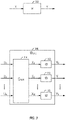
- a binary-input discrete memoryless channel 302 may be represented as W: X ⁇ Y, where X is an input and Y is an output of a channel W.
- an effective channel W VEC 308 for multiple inputs may be represented as follows.
- a transformation may include the following operations.
- a one-to-one mapping G N ⁇ N 310 is applied from U inputs (U 0 , U 1 , .... U N ) to X outputs (X 0 , X 1 ..., X N ) as set forth in Equation 1 of Table 1.
- G N ⁇ N may be represented as set forth in Equation 2 of Table 1.
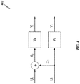
- Equation 3 of Table 1 Assuming W is a binary erasure channel (BEC) with an erasure probability ' ⁇ '. the relationships set forth in Equation 3 of Table 1 are true (with reference to the schematic 400 of FIG. 4 ).
- U 0 is an input and Y 0 is an output for a channel W 0
- U 1 is an input and Y 1 is an output for a channel W 1 .
- the erasure probability ( ⁇ - ) is set forth in Equation 4 of Table 1.
- the erasure probability ( ⁇ + ) is set forth in Equation 5 of Table 1.
- W 1 is a better channel than W 0 . Accordingly, U 1 will have a higher reliability than U 0 under SC decoding. The above operation can be performed recursively, yielding more polarization across N.
- codes may be rate-compatible. For example, coded bits may be punctured to meet the constraint of allocation.
- coded bits may be repeated to meet the constraint of the allocation. For example, start with a fixed N and repeat to meet the allocation size.
- the encoder/decoder complexity may be lower in this case as compared with starting from 2N and puncturing.
- the disclosure relates in some aspects to attempting to find the best scheme to puncture/repeat given a base polar code.
- BEC density evolution is more tractable to predict performance.
- teachings herein are applicable to any channel model.
- FIG. 5 illustrates a high-level example of an encoder structure 500 where bits for puncture or repetition may be selected in accordance with the teachings herein.
- Input bits are operated on by an initial stage (or stages) 502 and a final stage 504 of the encoder structure to provide a set of output bits.
- the final stage 504 includes several logical blocks (e.g., XORs). To reduce the complexity of FIG. 5 , only two logical blocks 506 and 508 are shown. It should be appreciated that the final stage 504 may include more logical blocks.
- logical blocks e.g., XORs
- certain bits of the output bits are selected 510 to be punctured or repeated by a puncture puncture/repetition stage 512. For example, selection of a bit tuple that consist of an input and an output of the same logical block may be avoided. As discussed in more detail below, this selection may result in improved performance of the encoding.
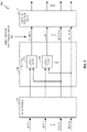
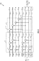
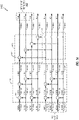
- FIGs. 6-13 illustrate several examples of encoders 600 - 1300 for generating puncture patterns where bits to be punctured do not include an input and an output of the same logical block in accordance with the teachings herein.
- Other values may be used in other scenarios.
- the values shown in these figures indicate the erasure probability of the corresponding bit. The erasure probabilities may have different values in different scenarios.
- Step 1 Puncturing: Take a non-bit-reversed polar code construction. Assume P out of N output bits are to be punctured. One of the better puncturing schemes is to pick the top-P consecutive encoded bits and puncture ( FIG. 6 ) or the bottom-P consecutive encoded bits and puncture ( FIG. 8 ). These are equivalent methods from, for example, an erasure probability perspective.
- Step 2 Freezing bits: Given K (# of information bits to be encoded) is ⁇ N, some of the information bits are to be frozen.
- the frozen bits can be selected based on density evolution subject to the puncturing pattern described herein.
- a defined (e.g., pre-defined) frozen bit sequence e.g., that might be sub-optimal) could be used. Similar frozen bit techniques could be used for repetition as well.
- the erasure probability for each bit may be calculated (e.g., the numbers 1, 0.75, 0.5, etc., above the data paths (information paths) as shown in FIGs. 6 - 13 ) and the information bits are sent over the bits with the lowest erasure probabilities.
- each encoder 600 - 1300 includes inputs bits (e.g., bits 602-0 to 602-7 in FIG. 6 ) and output bits (e.g., bits 604-0 to 604-7 in FIG. 6 ) associated with corresponding error probabilities.
- Each encoder also includes an input stage, and a final stage that includes an XOR group (e.g., XOR group 608 in FIG. 6 ) and repetition paths (e.g., paths 610 in FIG. 6 ).
- XORs are represented by a standard XOR symbols (e.g., the XOR 612 and the XOR 614 in FIG 6 ).
- FIGs. 7-13 illustrate similar structure as FIG. 6 with like features indicated by similar numbering.
- FIG. 6 shown an example of top puncturing (i.e., puncturing bits from the top half of the output bits).
- Each of the XORs of the XOR group 608 correspond to the XOR of FIG. 4 (e.g., the parity-check path U 0 of the Polar encoding function).
- each of the four paths 610 below the XOR group 608 correspond to the repetition path U 1 of FIG. 3 .
- each XOR in the XOR group 608 has an output and what is referred to herein as a repetition input (corresponding to the structure of FIG. 4 ).
- the XOR 614 has an output bit 604-0 and a repetition input bit 604-4.
- the XOR group 608 may be referred to as the last stage of the encoder graph.
- the punctured bits 622 do not include both the output and the repetition input of any of the four XORs of the XOR group 608.
- the output bit of the XOR 614 (the output bit 604-0) is punctured, but the repetition input of the XOR 614 (the output bit 604-4) is not punctured. If both the output and the repetition input to one of these XORs was punctured, the performance (e.g., reliability) of the encoding/decoding would generally be worse.
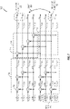
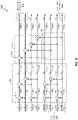
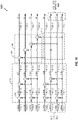
- Puncture can be split between the top (beginning) half and the bottom (end) half of the output bits as shown for the encoder 700 in FIG. 7 .
- the bits to be punctured 722 include outputs bits 704-0, 704-1, and 704-6.
- the bit swap 724 of FIG. 7 is relative to FIG. 6 .
- the output bit 704-6 is punctured instead of the output bit 704-2 (contrast FIG. 6 where the punctured bits 622 include the output bit 604-2).
- the punctured bits 722 do not include both the output and the repetition input of any of the four XORs of the XOR group 708.
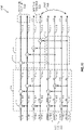
- FIG. 8 illustrates the erasure probability equivalence between bottom-puncturing (i.e., puncturing bits from the bottom half of the output bits) and the top-puncturing of FIG. 6 .
- the encoder 800 shows an example of bottom-puncturing where the bits to be punctured 822 include outputs bits 804-5, 804-6, and 804-7, all of which are from the bottom half of the output bits. This is in contrast with FIG. 6 where all of the punctured bits 622 are from the top half of the output bits.
- the punctured bits 822 do not include both the output and the repetition input of any of the four XORs of the XOR group 808.
- the encoder 900 of FIG. 9 shows another way that puncture bits can be split between the top (beginning) half and the bottom (end) half of the output bits.
- the bits to be punctured 922 include outputs bits 904-1, 904-6, and 904-7.
- the bit swap 924 of FIG. 9 is relative to FIG. 8 .
- the output bit 904-1 is punctured instead of the output bit 904-5 (contrast FIG. 8 where the punctured bits 822 include the output bit 804-5).
- the punctured bits 922 do not include both the output and the repetition input of any of the four XORs of the XOR group 908.
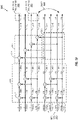
- the encoder 1000 of FIG. 10 illustrates another way to split the bits for puncturing to achieve the same erasure probability results as the encoders 600 - 900.
- the puncture split is between the top (beginning) and the bottom (end) of the output bits.
- the bits to be punctured 1022 include outputs bits 1004-0, 1004-1, and 1004-7.
- the punctured bits 1022 do not include both the output and the repetition input of any of the four XORs of the XOR group 1008.
- FIG. 11 shows another example of top-puncturing achieved with a bit swap 1124 relative to FIG. 10 .
- the output bit 1104-3 is punctured instead of the output bit 1104-7 (contrast FIG. 10 where the punctured bits 1022 include the output bit 1004-7).
- the punctured bits 1122do not include both the output and the repetition input of any of the four XORs of the XOR group 1108.
- the encoder 1200 of FIG. 12 illustrates another way to split the punctured bits to achieve the same erasure probability results as the encoders 600 - 1100.
- the bits to be punctured 1222 include outputs bits 1204-0, 1204-6, and 1204-7.
- the punctured bits 1222 do not include both the output and the repetition input of any of the four XORs of the XOR group 1208.
- FIG. 13 shows another example of top-puncturing achieved with a bit swap 1324 relative to FIG. 12 .
- the output bits 1304-2 and 1304-3 are punctured instead of the output bits 1304-6 and 1304-7 (contrast FIG. 12 where the punctured bits 1222 include the output bits 1204-6 and 1204-7).
- the punctured bits 1322 do not include both the output and the repetition input of any of the four XORs of the XOR group 1308.
- the punctured bits do not include both the output and the repetition input of an XOR of any of the XORs of the XOR group 402 (e.g., the parity-check XOR group).
- the actual configuration selected may depend on various criteria. For example, it may be easier to use contiguous bits. As another example (e.g., an OFDM scenario), some of the bits may be subjected to channel fading. Thus, these bits may be better candidates for puncture. It should be appreciated that other configurations (e.g., with a different number of punctured bits, a different number of output bits, different bit splitting, different bit grouping, etc.) may be used in accordance with the teachings herein.
- Puncture-set pick one from each of the tuples (0, N/2), (1, N/2 + 1), ..., (i, N/2+i), ..., (P-1, N/2 + P - 1).
- Puncture-set pick one from each of the tuples (N/2-1, N-1), (N/2 - 2, N - 2), ..., (N/2 -i, N - i), ..., (N/2 - P, N - P).
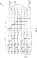
- FIGs. 14 - 17 illustrate several examples of encoders 1400 - 1700 for generating repetition patterns where bits to be repeated do not include an input and an output of the same logical block in accordance with the teachings herein.
- the number of bits N 8
- the number of repetition bits P 3
- the number of information bits to be encoded K 3.
- Other values may be used in other scenarios.
- the values shown in these figures indicate the erasure probability of the corresponding bit. The erasure probabilities may have different values in different scenarios.
- the following schemes illustrate examples of how to pick indexes of encoded bits of polar code (length-N) for repeating P positions.
- the same criterion is used for selecting the indexes for repetition as was used for selecting the indexes for puncturing.
- the repeated bits do not include the output and the repetition input of any of the XORs of the parity-check XOR group. If both the output and the repetition input of one of these XORs was repeated, the performance (e.g., reliability) gain of the encoding/decoding would not be as significant. However, if at most one of the output and the repetition input of these XORs is repeated, the performance gain may be higher.
- each encoder 1400 - 1700 includes inputs bits (e.g., bits 1402-0 to 1402-7 in FIG. 14 ) and output bits (e.g., bits 1404-0 to 1404-7 in FIG. 14 ) associated with corresponding error probabilities (e.g., the numbers 1, 0.75, 0.5, etc., above the data paths (information paths)).
- Each encoder also includes an input stage, and a final stage that includes an XOR group (e.g., XOR group 1408 in FIG. 14 ) and repetition paths (e.g., paths 1410 in FIG. 14 ).
- XORs are represented by a standard XOR symbols (e.g., the XOR 1412 and the XOR 1414 in FIG.
- FIGs. 15 - 17 illustrate similar structure as FIG. 14 with like features indicated by similar numbering. In general, any of the structures of FIGs. 6 - 13 may be applicable to repetition as well.
- FIG. 14 shown an example of top repeating (i.e., repeating bits from the top half of the output bits).
- the repeated bits 1422 do not include both the output and the repetition input of any of the XORs of the XOR group 1408.
- the output bit of the XOR 1414 (the output bit 1404-0) is repeated, but the repetition input of the XOR 1414 (the output bit 1404-4) is not repeated.
- the XORs of the XOR group 1408 correspond to the XOR of FIG. 4 (e.g., the parity-check path of the Polar encoding graph).
- the bits to be repeated 1522 include outputs bits 1504-0, 1504-1, and 1504-6.
- the bit swap 1524 of FIG. 15 is relative to FIG. 14 .
- the output bit 1504-6 is repeated instead of the output bit 1504-2 (contrast FIG. 14 where the repreated bits 1422 include the output bit 1404-2) .
- the repeated bits 1522 do not include both the output and the repetition input of any of the four XORs of the XOR group 1508.
- FIG. 16 illustrates the erasure probability equivalence between bottom-repeating (i.e., repeating bits from the bottom half of the output bits) and the top-repeating of FIG. 14 .
- the encoder 1600 shows an example of bottom-repeating where the bits to be repeated 1622 include outputs bits 1604-5, 1604-6, and 1604-7, all of which are from the bottom half of the output bits. This is in contrast with FIG. 14 where all of the repeated bits 1422 are from the top half of the output bits.
- the repeated bits 1622 do not include both the output and the repetition input of any of the four XORs of the XOR group 1608.
- FIG. 17 shows another way that repeat bits can be split between the top (beginning) half and the bottom (end) half of the output bits.
- the bits to be repeated 1722 include outputs bits 1704-1, 1704-6, and 1704-7.
- the bit swap 1724 of FIG. 17 is relative to FIG. 16 .
- the output bit 1704-1 is repeated instead of the output bit 1704-5 (contrast FIG. 16 where the repeated bits 1622 include the output bit 1604-5).
- the repeated bits 1722 do not include both the output and the repetition input of any of the four XORs of the XOR group 1708.
- the repeated bits do not include both the output and the repetition input of an XOR of any of the XORs of the XOR group 402 (e.g., the parity-check XOR group).
- the actual configuration selected may depend on various criteria. For example, it may be easier to use contiguous bits. It should be appreciated that other configurations (e.g., with a different number of repeated bits, a different number of output bits, different bit splitting, different bit grouping, etc.) may be used in accordance with the teachings herein.
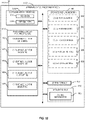
- FIG. 18 is an illustration of an apparatus 1800 that may use encoding according to one or more aspects of the disclosure.
- the apparatus 1800 could embody or be implemented within a UE, a TRP, a gNB, an access point, or some other type of device that uses encoding.
- the apparatus 1800 could embody or be implemented within an access terminal, a base station, or some other type of device.
- the apparatus 1800 could embody or be implemented within a mobile phone, a smart phone, a tablet, a portable computer, a server, a personal computer, a sensor, an alarm, a vehicle, a machine, an entertainment device, a medical device, or any other electronic device having circuitry.
- the apparatus 1800 includes a communication interface 1802 (e.g., at least one transceiver), a storage medium 1804, a user interface 1806, a memory device 1808, and a processing circuit 1810 (e.g., at least one processor). These components can be coupled to and/or placed in electrical communication with one another via a signaling bus or other suitable component, represented generally by the connection lines in FIG. 18 .
- the signaling bus may include any number of interconnecting buses and bridges depending on the specific application of the processing circuit 1810 and the overall design constraints.
- the signaling bus links together various circuits such that each of the communication interface 1802, the storage medium 1804, the user interface 1806, and the memory device 1808 are coupled to and/or in electrical communication with the processing circuit 1810.
- the signaling bus may also link various other circuits (not shown) such as timing sources, peripherals, voltage regulators, and power management circuits, which are well known in the art, and therefore, will not be described any further.
- the communication interface 1802 may be adapted to facilitate wireless communication of the apparatus 1800.
- the communication interface 1802 may include circuitry and/or programming adapted to facilitate the communication of information bi-directionally with respect to one or more communication devices in a network.
- the communication interface 1802 may be coupled to one or more antennas 1812 for wireless communication within a wireless communication system.
- the communication interface 1802 may be configured for wire-based communication.
- the communication interface 1802 could be a bus interface, a send/receive interface, or some other type of signal interface including drivers, buffers, or other circuitry for outputting and/or obtaining signals (e.g., outputting signals from and/or receiving signals into an integrated circuit).
- the communication interface 1802 can be configured with one or more standalone receivers and/or transmitters, as well as one or more transceivers.
- the communication interface 1802 includes a transmitter 1814 and a receiver 1816.
- the memory device 1808 may represent one or more memory devices. As indicated, the memory device 1808 may maintain coding-related information 1818 along with other information used by the apparatus 1800. In some implementations, the memory device 1808 and the storage medium 1804 are implemented as a common memory component. The memory device 1808 may also be used for storing data that is manipulated by the processing circuit 1810 or some other component of the apparatus 1800.
- the storage medium 1804 may represent one or more computer-readable, machine-readable, and/or processor-readable devices for storing programming, such as processor executable code or instructions (e.g., software, firmware), electronic data, databases, or other digital information.
- the storage medium 1804 may also be used for storing data that is manipulated by the processing circuit 1810 when executing programming.
- the storage medium 1804 may be any available media that can be accessed by a general purpose or special purpose processor, including portable or fixed storage devices, optical storage devices, and various other mediums capable of storing, containing or carrying programming.
- the storage medium 1804 may include a magnetic storage device (e.g., hard disk, floppy disk, magnetic strip), an optical disk (e.g., a compact disc (CD) or a digital versatile disc (DVD)), a smart card, a flash memory device (e.g., a card, a stick, or a key drive), a random access memory (RAM), a read only memory (ROM), a programmable ROM (PROM), an erasable PROM (EPROM), an electrically erasable PROM (EEPROM), a register, a removable disk, and any other suitable medium for storing software and/or instructions that may be accessed and read by a computer.
- a magnetic storage device e.g., hard disk, floppy disk, magnetic strip
- an optical disk e.g., a compact disc (CD) or a digital versatile disc (DVD)
- a smart card e.g., a flash memory device (e.g., a card, a stick, or
- the storage medium 1804 may be embodied in an article of manufacture (e.g., a computer program product).
- a computer program product may include a computer-readable medium in packaging materials.
- the storage medium 1804 may be a non-transitory (e.g., tangible) storage medium.
- the storage medium 1804 may be coupled to the processing circuit 1810 such that the processing circuit 1810 can read information from, and write information to, the storage medium 1804. That is, the storage medium 1804 can be coupled to the processing circuit 1810 so that the storage medium 1804 is at least accessible by the processing circuit 1810, including examples where at least one storage medium is integral to the processing circuit 1810 and/or examples where at least one storage medium is separate from the processing circuit 1810 (e.g., resident in the apparatus 1800, external to the apparatus 1800, distributed across multiple entities, etc.).
- the storage medium 1804 when executed by the processing circuit 1810, causes the processing circuit 1810 to perform one or more of the various functions and/or process operations described herein.
- the storage medium 1804 may include operations configured for regulating operations at one or more hardware blocks of the processing circuit 1810, as well as to utilize the communication interface 1802 for wireless communication utilizing their respective communication protocols.
- the storage medium 1104 may be a non-transitory computer-readable medium storing computer-executable code, including code to perform operations as described herein.
- the processing circuit 1810 is generally adapted for processing, including the execution of such programming stored on the storage medium 1804.
- code or “programming” shall be construed broadly to include without limitation instructions, instruction sets, data, code, code segments, program code, programs, programming, subprograms, software modules, applications, software applications, software packages, routines, subroutines, objects, executables, threads of execution, procedures, functions, etc., whether referred to as software, firmware, middleware, microcode, hardware description language, or otherwise.
- the processing circuit 1810 is arranged to obtain, process and/or send data, control data access and storage, issue commands, and control other desired operations.
- the processing circuit 1810 may include circuitry configured to implement desired programming provided by appropriate media in at least one example.
- the processing circuit 1810 may be implemented as one or more processors, one or more controllers, and/or other structure configured to execute executable programming.
- Examples of the processing circuit 1810 may include a general purpose processor, a digital signal processor (DSP), an application specific integrated circuit (ASIC), a field programmable gate array (FPGA) or other programmable logic component, discrete gate or transistor logic, discrete hardware components, or any combination thereof designed to perform the functions described herein.
- DSP digital signal processor
- ASIC application specific integrated circuit
- FPGA field programmable gate array
- a general purpose processor may include a microprocessor, as well as any conventional processor, controller, microcontroller, or state machine.
- the processing circuit 1810 may also be implemented as a combination of computing components, such as a combination of a DSP and a microprocessor, a number of microprocessors, one or more microprocessors in conjunction with a DSP core, an ASIC and a microprocessor, or any other number of varying configurations. These examples of the processing circuit 1810 are for illustration and other suitable configurations within the scope of the disclosure are also contemplated.
- the processing circuit 1810 may be adapted to perform any or all of the features, processes, functions, operations and/or routines for any or all of the apparatuses described herein.
- the processing circuit 1810 may be configured to perform any of the steps, functions, and/or processes described with respect to FIGs. 1 - 17 , 19 , and 20 .
- the term "adapted" in relation to the processing circuit 1810 may refer to the processing circuit 1810 being one or more of configured, used, implemented, and/or programmed to perform a particular process, function, operation and/or routine according to various features described herein.
- the processing circuit 1810 may be a specialized processor, such as an application specific integrated circuit (ASIC) that serves as a means for (e.g., structure for) carrying out any one of the operations described in conjunction with FIGs. 1 - 17 , 19 , and 20 .
- the processing circuit 1810 may serve as one example of a means for transmitting and/or a means for receiving.
- the processing circuit 1810 may provide and/or incorporate, at least in part, the functionality described above for the first wireless communication device 202 (e.g., the encoder 212) of FIG. 2 .
- the processing circuit 1810 may include one or more of a circuit/module for obtaining 1820, a circuit/module for encoding 1822, a circuit/module for modifying 1824, a circuit/module for outputting 1826, or a circuit/module for selecting 1828.
- the circuit/module for obtaining 1820, the circuit/module for encoding 1822, the circuit/module for modifying 1824, the circuit/module for outputting 1826, or the circuit/module for selecting 1828 may provide and/or incorporate, at least in part, the functionality described above for the first wireless communication device 202 (e.g., the encoder 212) of FIG. 2 .
- programming stored by the storage medium 1804 when executed by the processing circuit 1810, causes the processing circuit 1810 to perform one or more of the various functions and/or process operations described herein.
- the programming may cause the processing circuit 1810 to perform the various functions, steps, and/or processes described herein with respect to FIGs. 1 - 17 , 19 , and 20 in various implementations.
- the storage medium 1804 may include one or more of code for obtaining 1830, code for encoding 1832, code for modifying 1834, code for outputting 1836, or code for selecting 1838.
- the code for obtaining 1830, the code for encoding 1832, the code for modifying 1834, the code for outputting 1836, of the code for selecting 1838 may be executed or otherwise used to provide the functionality described herein for the circuit/module for obtaining 1820, the circuit/module for encoding 1822, the circuit/module for modifying 1824, the circuit/module for outputting 1826, or the circuit/module for selecting 1828.
- the circuit/module for obtaining 1820 may include circuitry and/or programming (e.g., code for obtaining 1830 stored on the storage medium 1804) adapted to perform several functions relating to, for example, obtaining information (which may also be referred to as data).
- the circuit/module for obtaining 1820 may receive information (e.g., from the communication interface 1802, the memory device 1808, or some other component of the apparatus 1800) and process (e.g., decode) the information.
- the circuit/module for obtaining 1820 may receive information directly from a device that transmitted the information. In either case, the circuit/module for obtaining 1820 may output the obtained information to another component of the apparatus 1800 (e.g., the circuit/module for encoding 1822, the memory device 1808, or some other component).
- the circuit/module for obtaining 1820 may take various forms.
- the circuit/module for obtaining 1820 may correspond to, for example, a processing circuit as discussed herein.
- the circuit/module for obtaining 1820 may correspond to, for example, an interface (e.g., a bus interface, a receive interface, or some other type of signal interface), a communication device, a transceiver, a receiver, or some other similar component as discussed herein.
- the communication interface 1802 includes the circuit/module for obtaining 1820 and/or the code for obtaining 1830.
- the circuit/module for obtaining 1820 and/or the code for obtaining 1830 is configured to control the communication interface 1802 (e.g., a transceiver or a receiver) to communicate the information.
- the circuit/module for encoding 1822 may include circuitry and/or programming (e.g., code for encoding 1832 stored on the storage medium 1804) adapted to perform several functions relating to, for example, encoding information.
- the circuit/module for encoding 1822 e.g., a means for encoding
- the circuit/module for encoding 1822 may execute an encoding algorithm on at least one input (e.g., obtained from the circuit/module for obtaining 1820, the memory device 1808, or some other component of the apparatus 1800). For example, the circuit/module for encoding 1822 may perform a block coding algorithm or a Polar coding algorithm. In some aspects, the circuit/module for encoding 1822 may perform one or more of the encoding-related operations described above in conjunction with FIGs. 1 - 17 . The circuit/module for encoding 1822 then outputs the resulting encoded information (e.g., to the circuit/module for modifying 1824, the communication interface 1802, the memory device 1808, or some other component).
- the circuit/module for encoding 1822 may execute an encoding algorithm on at least one input (e.g., obtained from the circuit/module for obtaining 1820, the memory device 1808, or some other component of the apparatus 1800). For example, the circuit/module for encoding
- the circuit/module for modifying 1824 may include circuitry and/or programming (e.g., code for modifying 1834 stored on the storage medium 1804) adapted to perform several functions relating to, for example, modifying a codeword.
- the circuit/module for modifying 1824 e.g., a means for modifying
- the circuit/module for modifying 1824 may obtain input information (e.g., from the means for encoding 1822, the memory device 1808, or some other component). For example, the circuit/module for modifying 1824 may modify a received codeword in conjunction with a puncture operation or a repetition operation (e.g., as described above in conjunction with FIGs. 1 - 17 ). The circuit/module for modifying 1824 may then generate an output based on the modifying (e.g., a modified codeword) and provide the output to a component of the apparatus 1800 (e.g., the circuit/module for outputting 1826, the memory device 1808, or some other component).
- a component of the apparatus 1800 e.g., the circuit/module for outputting 1826, the memory device 1808, or some other component.
- the circuit/module for outputting 1826 may include circuitry and/or programming (e.g., code for outputting 1836 stored on the storage medium 1804) adapted to perform several functions relating to, for example, outputting (e.g., sending or transmitting) information.
- the circuit/module for outputting 1826 may obtain information (e.g., from the circuit/module for modifying 1824, the memory device 1808, or some other component of the apparatus 1800) and process the information (e.g., encode the information for transmission).
- the circuit/module for outputting 1826 sends the information to another component (e.g., the transmitter 1814, the communication interface 1802, or some other component) that will send the information to another device.
- the circuit/module for outputting 1826 transmits the information directly to another device (e.g., the ultimate destination) via radio frequency signaling or some other type of signaling suitable for the applicable communication medium.
- the circuit/module for outputting 1826 may take various forms.
- the circuit/module for outputting 1826 may correspond to, for example, a processing circuit as discussed herein.
- the circuit/module for outputting 1826 may correspond to, for example, an interface (e.g., a bus interface, a send interface, or some other type of signal interface), a communication device, a transceiver, a transmitter, or some other similar component as discussed herein.
- the communication interface 1802 includes the circuit/module for outputting 1826 and/or the code for outputting 1836.
- the circuit/module for outputting 1826 and/or the code for outputting 1836 is configured to control the communication interface 1802 (e.g., a transceiver or a transmitter) to transmit information.
- the circuit/module for selecting 1828 may include circuitry and/or programming (e.g., code for selecting 1838 stored on the storage medium 1804) adapted to perform several functions relating to, for example, selecting a pattern.
- the circuit/module for selecting 1828 e.g., a means for selecting
- the circuit/module for selecting 1828 may make a selection based on one or more inputs.
- the circuit/module for selecting 1828 may initially obtain input information (e.g., from the memory device 1808, or some other component of the apparatus 1800).
- the circuit/module for selecting 1828 may select a puncture pattern or a repetition pattern based on consecutive bits, bit tuples, or other information (e.g., as described above in conjunction with FIGs. 1 - 17 ).
- the circuit/module for selecting 1828 may then output an indication of the selection (e.g., to the circuit/module for modifying 1824, the memory device 1808, an encoder, or some other component).
- the teachings herein may be used to improve the encoding performance the apparatus 1800 (e.g., improve the encoding performance of the processing circuit 1810).
- the processing circuit 1810 may provide more reliable encoding as compared to the encoding the processing circuit 1810 may provide if some other puncturing scheme and/or repetition scheme was used. This higher reliability may be achieved, for example, by sending information over the bits with the lowest erasure probabilities as discussed above. Thus, fewer retransmissions may be needed by using puncturing and/or repetition as taught herein instead of other puncturing and repetition schemes that do not encode information in this manner.
- FIG. 19 illustrates a process 1900 for communication in accordance with some aspects of the disclosure.
- the process 1900 may take place within a processing circuit (e.g., the processing circuit 1810 of FIG. 18 ), which may be located in an access terminal, a TRP, a gNB, a base station, or some other suitable apparatus (e.g., that provides encoding).
- a processing circuit e.g., the processing circuit 1810 of FIG. 18
- the process 1900 may be implemented by any suitable apparatus capable of supporting communication-related operations.
- an apparatus may select a puncture pattern.
- the selection of the puncture pattern may include selecting a set of consecutive bits at a beginning of the codeword.
- the selection of the puncture pattern may include selecting a set of consecutive bits at an end of the codeword.
- the selection of the puncture pattern may include selecting a bit of the codeword that is a particular output of a last stage of an encoder for the encoding (e.g., the last stage of the Polar coding function), and not selecting a bit of the codeword that is an input of an XOR for the particular output of the last stage.
- the selection of the puncture pattern may include dividing bits of the codeword into bit pairs, and selecting at most one bit from each bit pair as a bit to be punctured.
- the bit pairs may be mutually exclusively associated with XORs of a last stage of an encoder for the encoding, and bits of a particular bit pair of the bit pairs may be mutually exclusively associated with an output of a particular XOR of the XORs and a repetition input of the particular XOR.
- the selection of the puncture pattern may include selecting between a set of consecutive bits at a beginning of the codeword, or a set of consecutive bits at an end of the codeword.
- the selection of the puncture pattern may include selecting bits of the codeword that are not the output and the repetition input of the same XOR of a last stage of an encoder graph for the encoding (e.g., the last stage of the Polar coding function).
- the selection of the puncture pattern may include dividing bits of the codeword into bit pairs and, for each bit pair, selecting at most one bit from the bit pair as a bit to be punctured.
- the bit pairs may be mutually exclusively associated with XORs of a last stage of an encoder graph for the encoding and, for each of the bit pairs, the bits of the bit pair may be mutually exclusively associated with the output and the repetition input of the associated XOR.
- circuit/module for selecting 1828 of FIG. 18 performs the operations of block 1902.
- code for selecting 1838 of FIG. 18 is executed to perform the operations of block 1902.
- the apparatus obtains data.
- the apparatus may retrieve the data from memory or receive the data from another apparatus.
- data refers to information generally.
- data may include user data, control information, and so on.
- the circuit/module for obtaining 1820 of FIG. 18 performs the operations of block 1904. In some implementations, the code for obtaining 1830 of FIG. 18 is executed to perform the operations of block 1904.
- the apparatus encodes the data to generate a codeword.
- the encoding may include Polar coding.
- the circuit/module for encoding 1822 of FIG. 18 performs the operations of block 1906.
- the code for encoding 1832 of FIG. 18 is executed to perform the operations of block 1906.
- the apparatus modifies the codeword according to a puncture pattern that is based on a plurality of bit tuples.
- a puncture bit At most one bit of a particular bit tuple of the plurality of bit tuples is designated as a puncture bit.
- the bit tuples may be mutually exclusively associated with logical blocks of a particular stage of an encoder for the encoding.
- the logical blocks may be XORs.
- a first one of the XORs may be part of a first path of the particular stage of the encoder, and a second one of the XORs may be part of a second path of the particular stage of the encoder.
- the particular stage may include (e.g., may be) a last stage prior to puncture of the codeword.
- the particular bit tuple may be associated with an XOR of an encoder for the encoding
- the particular bit tuple may include a first bit and a second bit
- the first bit and the second bit may be mutually exclusively associated with an output of the XOR and a repetition input of the XOR.
- the particular bit tuple may be associated with an XOR of an encoder for the encoding, an input of the XOR may include (e.g., may be) a first output of the encoder, and an output of the XOR may include (e.g., may be) a second output of the encoder.
- bit tuples at most one bit of the bit tuple is designated as a puncture bit, and bits of the bit tuple may be mutually exclusively associated with an output and a repetition input of an associated XOR.
- bit tuples may be mutually exclusively associated with XORs of a last stage of an encoder graph for the encoding and, for each of the bit tuples, the bits of the bit tuple may be mutually exclusively associated with the output and the repetition input of the associated XOR.
- each XOR may be part of a corresponding parity check path of the Polar coding function (e.g., in the last stage of the encoder graph).
- the circuit/module for modifying 1824 of FIG. 18 performs the operations of block 1908.
- the code for modifying 1834 of FIG. 18 is executed to perform the operations of block 1908.
- the apparatus outputs (e.g., transmits) the modified codeword.
- the apparatus may store the modified codeword in memory or send the modified codeword to another apparatus.
- the apparatus may transmit the modified codeword via an antenna to another apparatus (e.g., via RF signaling).
- the circuit/module for outputting 1826 of FIG. 18 performs the operations of block 1910.
- the code for outputting 1836 of FIG. 18 is executed to perform the operations of block 1910.
- the process 1900 may include any combination of the operations described above for FIG. 19 .
- FIG. 20 illustrates a process 2000 for communication in accordance with some aspects of the disclosure.
- the process 2000 may take place within a processing circuit (e.g., the processing circuit 1810 of FIG. 18 ), which may be located in an access terminal, a TRP, a gNB, a base station, or some other suitable apparatus (e.g., that provides encoding).
- a processing circuit e.g., the processing circuit 1810 of FIG. 18
- the process 2000 may be implemented by any suitable apparatus capable of supporting communication-related operations.
- an apparatus may select a repetition pattern.
- the selection of the repetition pattern may include selecting a set of consecutive bits at a beginning of the codeword.
- the selection of the repetition pattern may include selecting a set of consecutive bits at an end of the codeword.
- the selection of the puncture pattern may include selecting a bit of the codeword that is a particular output of a last stage of an encoder for the encoding (e.g., the last stage of the Polar coding function), and not selecting a bit of the codeword that is an input of an XOR for the particular output of the last stage.
- the selection of the puncture pattern may include dividing bits of the codeword into bit pairs, and selecting at most one bit from each bit pair as a bit to be repeated.
- the bit pairs may be mutually exclusively associated with XORs of a last stage of an encoder for the encoding, and bits of a particular bit pair of the bit pairs may be mutually exclusively associated with an output of a particular XOR of the XORs and a repetition input of the particular XOR.
- the selection of the repetition pattern may include selecting between a set of consecutive bits at a beginning of the codeword, or a set of consecutive bits at an end of the codeword.
- the selection of the repetition pattern may include selecting bits of the codeword that are not the output and the repetition input of the same XOR of a last stage of an encoder graph for the encoding. In some aspects, the selection of the repetition pattern may include dividing bits of the codeword into bit pairs and, for each bit pair, selecting at most one bit from the bit pair as a bit to be repeated. In some aspects, the bit pairs may be mutually exclusively associated with XORs of a last stage of an encoder graph for the encoding and, for each of the bit pairs, the bits of the bit pair may be mutually exclusively associated with the output and the repetition input of the associated XOR.
- the circuit/module for selecting 1828 of FIG. 18 performs the operations of block 2002.
- the code for selecting 1838 of FIG. 18 is executed to perform the operations of block 2002.
- the apparatus obtains data.
- the apparatus may retrieve the data from memory or receive the data from another apparatus.
- data refers to information generally.
- data may include user data, control information, and so on.
- the circuit/module for obtaining 1820 of FIG. 18 performs the operations of block 2004.
- the code for obtaining 1830 of FIG. 18 is executed to perform the operations of block 2004.
- the apparatus encodes the data to generate a codeword.
- the encoding may include Polar coding.
- the circuit/module for encoding 1822 of FIG. 18 performs the operations of block 2006. In some implementations, the code for encoding 1832 of FIG. 18 is executed to perform the operations of block 2006.
- the apparatus modifies the codeword according to a repetition pattern that is based on a plurality of bit tuples.
- a repetition pattern that is based on a plurality of bit tuples.
- at most one bit of a particular bit tuple of the plurality of bit tuples is designated as a repeated bit.
- the bit tuples may be mutually exclusively associated with logical blocks of a particular stage of an encoder for the encoding.
- the logical blocks may be XORs.
- a first one of the XORs may be part of a first path of the particular stage of the encoder, and a second one of the XORs may be part of a second path of the particular stage of the encoder.
- the particular stage may include (e.g., may be) a last stage prior to repetition of the codeword.
- the particular bit tuple may be associated with an XOR of an encoder for the encoding, the particular bit tuple may include a first bit and a second bit, and the first bit and the second bit may be mutually exclusively associated with an output of the XOR and a repetition input of the XOR.
- the particular bit tuple may be associated with an XOR of an encoder for the encoding, an input of the XOR may include (e.g., may be) a first output of the encoder, and an output of the XOR may include (e.g., may be) a second output of the encoder.
- at most one bit of the bit tuple is designated as a repetition bit, and bits of the bit tuple may be mutually exclusively associated with an output and a repetition input of an associated XOR.
- bit tuples may be mutually exclusively associated with XORs of a last stage of an encoder graph for the encoding and, for each of the bit tuples, the bits of the bit tuple may be mutually exclusively associated with the output and the repetition input of the associated XOR.
- each XOR may be part of a corresponding parity check path of the Polar coding function.
- the circuit/module for modifying 1824 of FIG. 18 performs the operations of block 2008. In some implementations, the code for modifying 1834 of FIG. 18 is executed to perform the operations of block 2008.
- the apparatus outputs (e.g., transmits) the modified codeword.
- the apparatus may store the modified codeword in memory or send the modified codeword to another apparatus.
- the apparatus may transmit the modified codeword via an antenna to another apparatus (e.g., via RF signaling).
- the circuit/module for outputting 1826 of FIG. 18 performs the operations of block 2010.
- the code for outputting 1836 of FIG. 18 is executed to perform the operations of block 2010.
- the process 2000 may include any combination of the operations described above for FIG. 20 .
- One or more of the components, steps, features and/or functions illustrated in above may be rearranged and/or combined into a single component, step, feature or function or embodied in several components, steps, or functions. Additional elements, components, steps, and/or functions may also be added without departing from novel features disclosed herein.
- the apparatus, devices, and/or components illustrated above may be configured to perform one or more of the methods, features, or steps described herein.
- the novel algorithms described herein may also be efficiently implemented in software and/or embedded in hardware.
- a software module may reside in RAM memory, flash memory, ROM memory, EPROM memory, EEPROM memory, registers, hard disk, a removable disk, a CD-ROM, or any other form of storage medium known in the art.
- An example of a storage medium is coupled to the processor such that the processor can read information from, and write information to, the storage medium. In the alternative, the storage medium may be integral to the processor.
- any reference to an element herein using a designation such as "first,” “second,” and so forth does not generally limit the quantity or order of those elements. Rather, these designations may be used herein as a convenient method of distinguishing between two or more elements or instances of an element. Thus, a reference to first and second elements does not mean that only two elements may be used there or that the first element must precede the second element in some manner. Also, unless stated otherwise a set of elements may include one or more elements.
- terminology of the form “at least one of a, b, or c" or “one or more of a, b, or c” used in the description or the claims means “a or b or c or any combination of these elements.”
- this terminology may include a, or b, or c, or a and b, or a and c, or a and b and c, or 2a, or 2b, or 2c, or 2a and b, and so on.
- determining encompasses a wide variety of actions. For example, “determining” may include calculating, computing, processing, deriving, investigating, looking up (e.g., looking up in a table, a database or another data structure), ascertaining, and the like. Also, “determining” may include receiving (e.g., receiving information), accessing (e.g., accessing data in a memory), and the like. Also, “determining” may include resolving, selecting, choosing, establishing, and the like.
Landscapes
- Engineering & Computer Science (AREA)
- Physics & Mathematics (AREA)
- Probability & Statistics with Applications (AREA)
- Theoretical Computer Science (AREA)
- Signal Processing (AREA)
- Computer Networks & Wireless Communication (AREA)
- Quality & Reliability (AREA)
- Error Detection And Correction (AREA)
- Compression, Expansion, Code Conversion, And Decoders (AREA)
Claims (15)
- Verfahren zur Kommunikation, umfassend:Erhalten (1904) von Daten;Codieren (1906) der Daten, um ein Codewort zu erzeugen;Teilen des Codeworts in mehrere Bittupel;Modifizieren (1908) des Codeworts gemäß einem Punktionsmuster, das auf den mehreren Bittupeln basiert, wobei höchstens ein Bit eines bestimmten Bittupels der mehreren Bittupel als ein Punktionsbit bezeichnet wird, das ein zu punktierendes Bit ist; undÜbertragen (1910) des modifizierten Codeworts.
- Verfahren nach Anspruch 1, ferner umfassend:
Auswählen (1902) des Punktionsmusters;
insbesondere wobei die Auswahl des Punktionsmusters eine der folgenden Optionen i) bis iv) umfasst:i) Auswählen eines Satzes von aufeinanderfolgenden Bits an einem Anfang des Codeworts; oderii) Auswählen eines Satzes von aufeinanderfolgenden Bits an einem Ende des Codeworts; oderiii) Auswählen eines Bits des Codeworts, das eine bestimmte Ausgabe einer letzten Stufe eines Codierers für die Codierung ist, wobei die letzte Stufe einen Satz von Ausgabebits bereitstellt; und
Nicht-Auswählen eines Bits des Codeworts, das eine Eingabe eines XOR in einer XOR-Gruppe der letzten Stufe eines Codierers für die Codierung für die bestimmte Ausgabe der letzten Stufe ist; oderiv) Teilen von Bits des Codeworts in Bitpaare; und
Auswählen höchstens eines Bits aus jedem Bitpaar als ein zu punktierendes Bit. - Verfahren nach Anspruch 1, wobei für jedes der Bittupel:höchstens ein Bit des Bittupels als ein Punktionsbit ausgewiesen wird; undBits des Bittupels wechselseitig exklusiv mit einer Ausgabe und einer Wiederholungseingabe eines zugeordneten XOR in einer XOR-Gruppe einer letzten Stufe eines Codierers für die Codierung assoziiert sind, wobei die letzte Stufe einen Satz von Ausgabebits bereitstellt.
- Vorrichtung (1800) zur Kommunikation, umfassend:Mittel (1820) zum Erhalten von Daten;Mittel (1822) zum Codieren der Daten, um ein Codewort zu erzeugen;Mittel zum Teilen des Codeworts in mehrere Bittupel;Mittel (1824) zum Modifizieren des Codeworts gemäß einem Punktionsmuster, das auf den mehreren Bittupeln basiert, wobei höchstens ein Bit eines bestimmten Bittupels der mehreren Bittupel als ein Punktionsbit bezeichnet wird, das ein zu punktierendes Bit ist; undMittel (1826) zum Übertragen des modifizierten Codeworts.
- Vorrichtung (1800) nach Anspruch 4, ferner umfassend:
Mittel (1826) zum Auswählen des Punktionsmusters. - Verfahren zur Kommunikation, umfassend:Erhalten (2004) von Daten;Codieren (2006) der Daten, um ein Codewort zu erzeugen;Teilen des Codeworts in mehrere Bittupel;Modifizieren (2008) des Codeworts gemäß einem Wiederholungsmuster, das auf den mehreren Bittupeln basiert, wobei höchstens ein Bit eines bestimmten Bittupels der mehreren Bittupel als ein wiederholtes Bit ausgewiesen wird, das ein zu wiederholendes Bit ist; undÜbertragen (2010) des modifizierten Codeworts.
- Verfahren nach Anspruch 2 oder 6, wobei die Bittupel wechselseitig exklusivmit logischen Blöcken einer bestimmten Stufe eines Codierers für die Codierung assoziiert sind;insbesondere wobei die logischen Blöcke XORs sind;ferner insbesondere wobei: ein erstes der XORs Teil eines ersten Pfads der bestimmten Stufe des Codierers ist; und ein zweites der XORs Teil eines zweiten Pfads der bestimmten Stufe des Codierers ist.
- Verfahren nach Anspruch 6, umfassend eine der folgenden Optionen i) bis v):i) das bestimmte Bittupel ist mit einem XOR in einer XOR-Gruppe einer letzten Stufe eines Codierers für die Codierung assoziiert, wobei die letzte Stufe einen Satz von Ausgabebits bereitstellt;das bestimmte Bittupel umfasst ein erstes Bit und ein zweites Bit; unddas erste Bit und das zweite Bit sind wechselseitig exklusiv mit einer Ausgabe des XOR und einer Wiederholungseingabe des XOR assoziiert; oderii) das bestimmte Bittupel ist mit einem XOR in einer XOR-Gruppe einer letzten Stufe eines Codierers für die Codierung assoziiert, wobei die letzte Stufe einen Satz von Ausgabebits bereitstellt;eine Eingabe des XOR umfasst eine erste Ausgabe des Codierers; undeine Ausgabe des XOR umfasst eine zweite Ausgabe des Codierers; oderiii) Auswählen des Wiederholungsmusters;
insbesondere wobei die Auswahl des Wiederholungsmusters umfasst:
Auswählen eines Satzes von aufeinanderfolgenden Bits an einem Anfang des Codeworts; oderiv) wobei die Auswahl des Wiederholungsmusters umfasst:
Auswählen eines Satzes von aufeinanderfolgenden Bits an einem Ende des Codeworts; oderv) wobei die Auswahl des Wiederholungsmusters umfasst:
Auswählen eines Bits des Codeworts, das eine bestimmte Ausgabe einer letzten Stufe eines Codierers für die Codierung ist, wobei die letzte Stufe einen Satz von Ausgabebits bereitstellt; und
Nicht-Auswählen eines Bits des Codeworts, das eine Eingabe eines XOR in einer XOR-Gruppe der letzten Stufe eines Codierers für die Codierung für die bestimmte Ausgabe der letzten Stufe ist. - Verfahren nach Anspruch 6, ferner umfassend das Auswählen des Wiederholungsmusters, wobei die Auswahl des Wiederholungsmusters umfasst:Teilen von Bits des Codeworts in Bitpaare;Auswählen höchstens eines Bits aus jedem Bitpaar als ein zu wiederholendes Bit; undWiederholen mindestens eines ausgewählten Bits;insbesondere wobeidie Bitpaare wechselseitig exklusiv mit XOR in einer XOR-Gruppe einer letzten Stufe eines Codierers für die Codierung assoziiert sind, wobei die letzte Stufe einen Satz von Ausgabebits bereitstellt; undBits eines bestimmten Bitpaars der Bitpaare wechselseitig exklusiv mit einer Ausgabe eines bestimmten XOR der XOR und einer Wiederholungseingabe des bestimmten XOR assoziiert sind.
- Verfahren nach Anspruch 6, wobei für jedes der Bittupel:höchstens ein Bit des Bittupels als ein Wiederholungsbit ausgewiesen wird; undBits des Bittupels wechselseitig exklusiv mit einer Ausgabe und einer Wiederholungseingabe eines zugeordneten XOR in einer XOR-Gruppe einer letzten Stufe eines Codierers für die Codierung assoziiert sind, wobei die letzte Stufe einen Satz von Ausgabebits bereitstellt.
- Verfahren nach Anspruch 1 oder 6, wobei die Codierung Polarcodierung umfasst.
- Vorrichtung (1800) zur Kommunikation, umfassend:Mittel (1820) zum Erhalten von Daten;Mittel (1822) zum Codieren der Daten, um ein Codewort zu erzeugen;Mittel zum Teilen des Codeworts in mehrere Bittupel;Mittel (1824) zum Modifizieren des Codeworts gemäß einem Wiederholungsmuster, das auf den mehreren Bittupeln basiert, wobei höchstens ein Bit eines bestimmten Bittupels der mehreren Bittupel als ein wiederholtes Bit ausgewiesen wird, das ein zu wiederholendes Bit ist; undMittel (1826) zum Übertragen des modifizierten Codeworts.
- Vorrichtung (1800) nach Anspruch 12, wobei die Bittupel wechselseitig exklusiv mit XOR in einer XOR-Gruppe einer letzten Stufe eines Codierers für die Codierung assoziiert sind, wobei die letzte Stufe einen Satz von Ausgabebits bereitstellt; oder
wobei:das bestimmte Bittupel mit einem XOR in einer XOR-Gruppe einer letzten Stufe eines Codierers für die Codierung assoziiert ist, wobei die letzte Stufe einen Satz von Ausgabebits bereitstellt;eine Eingabe des XOR eine erste Ausgabe des Codierers umfasst; undeine Ausgabe des XOR eine zweite Ausgabe des Codierers umfasst. - Vorrichtung (1800) nach Anspruch 12, ferner umfassend:
Mittel (1828) zum Auswählen des Wiederholungsmusters. - Computerprogramm, umfassend computerlesbaren Code, der, wenn er auf einem Computer ausgeführt wird, den Computer veranlasst, das Verfahren nach einem der Ansprüche 1 bis 3 oder 6 bis 11 durchzuführen.
Applications Claiming Priority (2)
| Application Number | Priority Date | Filing Date | Title |
|---|---|---|---|
| PCT/CN2017/070985 WO2018129695A1 (en) | 2017-01-12 | 2017-01-12 | Puncturing and repetition for data encoding |
| PCT/CN2018/072319 WO2018130185A1 (en) | 2017-01-12 | 2018-01-12 | Puncturing and repetition for information encoding |
Publications (3)
| Publication Number | Publication Date |
|---|---|
| EP3568934A1 EP3568934A1 (de) | 2019-11-20 |
| EP3568934A4 EP3568934A4 (de) | 2020-12-16 |
| EP3568934B1 true EP3568934B1 (de) | 2022-08-10 |
Family
ID=62839146
Family Applications (1)
| Application Number | Title | Priority Date | Filing Date |
|---|---|---|---|
| EP18739077.8A Active EP3568934B1 (de) | 2017-01-12 | 2018-01-12 | Punktierung und wiederholung für informationscodierung |
Country Status (9)
| Country | Link |
|---|---|
| US (2) | US11044048B2 (de) |
| EP (1) | EP3568934B1 (de) |
| JP (1) | JP7220657B2 (de) |
| KR (1) | KR20190101401A (de) |
| CN (2) | CN110178327B (de) |
| BR (1) | BR112019014118A2 (de) |
| CA (1) | CA3046038A1 (de) |
| TW (1) | TWI775799B (de) |
| WO (2) | WO2018129695A1 (de) |
Families Citing this family (6)
| Publication number | Priority date | Publication date | Assignee | Title |
|---|---|---|---|---|
| WO2018129695A1 (en) * | 2017-01-12 | 2018-07-19 | Qualcomm Incorporated | Puncturing and repetition for data encoding |
| CN111405527B (zh) * | 2020-03-17 | 2021-08-10 | 中南大学 | 一种基于志愿者协同处理的车载边缘计算方法、装置及系统 |
| US11411779B2 (en) | 2020-03-31 | 2022-08-09 | XCOM Labs, Inc. | Reference signal channel estimation |
| CA3195885A1 (en) | 2020-10-19 | 2022-04-28 | XCOM Labs, Inc. | Reference signal for wireless communication systems |
| WO2022093988A1 (en) | 2020-10-30 | 2022-05-05 | XCOM Labs, Inc. | Clustering and/or rate selection in multiple-input multiple-output communication systems |
| KR20240052728A (ko) * | 2021-08-31 | 2024-04-23 | 엘지전자 주식회사 | 무선 통신 시스템에서 폴라 코드 기반의 인코더를 설정하기 위한 장치 및 방법 |
Family Cites Families (29)
| Publication number | Priority date | Publication date | Assignee | Title |
|---|---|---|---|---|
| ES2221446T3 (es) * | 1998-10-07 | 2004-12-16 | Siemens Aktiengesellschaft | Aparato y metodo de transmision de datos perforados o repetidos. |
| CA2268853C (en) * | 1999-04-13 | 2011-08-02 | Wen Tong | Rate matching and channel interleaving for a communications system |
| EP1176725B1 (de) * | 2000-07-05 | 2013-03-13 | LG Electronics Inc. | Verfahren zur Übertragungskonfiguration in einem mobilen Kommunikationssystem |
| US7242726B2 (en) * | 2000-09-12 | 2007-07-10 | Broadcom Corporation | Parallel concatenated code with soft-in soft-out interactive turbo decoder |
| US7415079B2 (en) * | 2000-09-12 | 2008-08-19 | Broadcom Corporation | Decoder design adaptable to decode coded signals using min* or max* processing |
| US6904097B2 (en) * | 2001-06-01 | 2005-06-07 | Motorola, Inc. | Method and apparatus for adaptive signaling in a QAM communication system |
| US6903665B2 (en) * | 2002-10-30 | 2005-06-07 | Spacebridge Semiconductor Corporation | Method and apparatus for error control coding in communication systems using an outer interleaver |
| KR100617770B1 (ko) * | 2003-12-24 | 2006-08-28 | 삼성전자주식회사 | 채널 부호화 장치 및 방법 |
| US7362251B2 (en) * | 2006-05-18 | 2008-04-22 | Broadcom Corporation | Method and system for digital to analog conversion for power amplifier driver amplitude modulation |
| CN101083512B (zh) * | 2006-06-02 | 2011-09-21 | 中兴通讯股份有限公司 | 一种双二进制咬尾Turbo码编码方法和装置 |
| US8352843B2 (en) * | 2007-03-16 | 2013-01-08 | Qualcomm Incorporated | Method and apparatus for coding a communication signal |
| US8904265B2 (en) * | 2007-05-02 | 2014-12-02 | Broadcom Corporation | Optimal period rate matching for turbo coding |
| US8358705B2 (en) * | 2007-07-05 | 2013-01-22 | Coherent Logix, Incorporated | Transmission of multimedia streams to mobile devices with uncoded transport tunneling |
| KR100983282B1 (ko) * | 2007-12-24 | 2010-09-24 | 엘지전자 주식회사 | 블록 코드를 이용한 다양한 길이를 가진 정보의 채널 코딩방법 |
| US7975189B2 (en) * | 2008-11-14 | 2011-07-05 | Trelliware Technologies, Inc. | Error rate estimation/application to code-rate adaption |
| CN101834694B (zh) * | 2009-03-11 | 2013-07-31 | 富士通株式会社 | 数据发送装置及其方法、数据接收装置及其方法 |
| US8689093B2 (en) * | 2009-12-07 | 2014-04-01 | Samsung Electronics Co., Ltd | Method and apparatus for channel encoding and decoding in a communication system using a low-density parity check code |
| US9094164B2 (en) * | 2012-04-17 | 2015-07-28 | Qualcomm Incorporated | Methods and apparatus to improve channel estimation in communication systems |
| WO2015100561A1 (zh) * | 2013-12-30 | 2015-07-09 | 华为技术有限公司 | 极化码的速率匹配方法及装置 |
| WO2015182102A1 (ja) * | 2014-05-30 | 2015-12-03 | パナソニックIpマネジメント株式会社 | 送信装置、受信装置、送信方法および受信方法 |
| JP6628124B2 (ja) | 2014-05-30 | 2020-01-08 | パナソニックIpマネジメント株式会社 | 送信装置、受信装置、送信方法および受信方法 |
| CN111711513B (zh) * | 2015-02-13 | 2023-08-04 | 三星电子株式会社 | 发送器及其附加奇偶校验产生方法 |
| KR102347779B1 (ko) * | 2015-03-13 | 2022-01-06 | 상하이 내셔널 엔지니어링 리서치 센터 오브 디지털 텔레비전 컴퍼니, 리미티드 | 시그널링 코딩 변조방법, 복조 디코딩 방법 및 장치 |
| CN106034007B (zh) * | 2015-03-13 | 2019-12-13 | 上海数字电视国家工程研究中心有限公司 | 信令编码调制方法和解调译码方法及装置 |
| GB2539925B (en) * | 2015-07-01 | 2017-09-20 | Canon Kk | DC free line coding robust against transmission error |
| WO2017196703A1 (en) * | 2016-05-11 | 2017-11-16 | Idac Holdings, Inc. | Code-domain non-orthogonal multiple access schemes |
| US10644829B2 (en) * | 2016-09-15 | 2020-05-05 | Huawei Technologies Co., Ltd. | Method and apparatus for encoding data using a polar code |
| WO2018129695A1 (en) * | 2017-01-12 | 2018-07-19 | Qualcomm Incorporated | Puncturing and repetition for data encoding |
| US10651973B2 (en) * | 2017-03-22 | 2020-05-12 | Huawei Technologies Co., Ltd. | Method and apparatus for error-correction encoding using a polar code |
-
2017
- 2017-01-12 WO PCT/CN2017/070985 patent/WO2018129695A1/en active Application Filing
-
2018
- 2018-01-12 BR BR112019014118-9A patent/BR112019014118A2/pt unknown
- 2018-01-12 TW TW107101231A patent/TWI775799B/zh active
- 2018-01-12 KR KR1020197019950A patent/KR20190101401A/ko not_active Application Discontinuation
- 2018-01-12 CA CA3046038A patent/CA3046038A1/en active Pending
- 2018-01-12 WO PCT/CN2018/072319 patent/WO2018130185A1/en unknown
- 2018-01-12 US US16/470,881 patent/US11044048B2/en active Active
- 2018-01-12 CN CN201880006309.8A patent/CN110178327B/zh active Active
- 2018-01-12 JP JP2019536941A patent/JP7220657B2/ja active Active
- 2018-01-12 EP EP18739077.8A patent/EP3568934B1/de active Active
- 2018-01-12 CN CN202111060450.6A patent/CN113794534A/zh active Pending
-
2021
- 2021-05-13 US US17/319,283 patent/US20210266100A1/en active Pending
Also Published As
| Publication number | Publication date |
|---|---|
| EP3568934A4 (de) | 2020-12-16 |
| US20200092041A1 (en) | 2020-03-19 |
| CN110178327A (zh) | 2019-08-27 |
| CA3046038A1 (en) | 2018-07-19 |
| TW201832476A (zh) | 2018-09-01 |
| WO2018129695A1 (en) | 2018-07-19 |
| EP3568934A1 (de) | 2019-11-20 |
| JP2020506581A (ja) | 2020-02-27 |
| KR20190101401A (ko) | 2019-08-30 |
| TWI775799B (zh) | 2022-09-01 |
| BR112019014118A2 (pt) | 2020-02-11 |
| JP7220657B2 (ja) | 2023-02-10 |
| WO2018130185A1 (en) | 2018-07-19 |
| US11044048B2 (en) | 2021-06-22 |
| CN113794534A (zh) | 2021-12-14 |
| US20210266100A1 (en) | 2021-08-26 |
| CN110178327B (zh) | 2021-09-07 |
Similar Documents
| Publication | Publication Date | Title |
|---|---|---|
| EP3568934B1 (de) | Punktierung und wiederholung für informationscodierung | |
| US11973518B2 (en) | Rate matching for block encoding | |
| US20220069841A1 (en) | Encoding and decoding techniques | |
| US10855405B2 (en) | Retransmission techniques for encoded transmissions | |
| US11616598B2 (en) | Puncturing and retransmission techniques for encoded transmissions | |
| US11259280B2 (en) | Sub-channel mapping |
Legal Events
| Date | Code | Title | Description |
|---|---|---|---|
| STAA | Information on the status of an ep patent application or granted ep patent |
Free format text: STATUS: THE INTERNATIONAL PUBLICATION HAS BEEN MADE |
|
| PUAI | Public reference made under article 153(3) epc to a published international application that has entered the european phase |
Free format text: ORIGINAL CODE: 0009012 |
|
| STAA | Information on the status of an ep patent application or granted ep patent |
Free format text: STATUS: REQUEST FOR EXAMINATION WAS MADE |
|
| 17P | Request for examination filed |
Effective date: 20190606 |
|
| AK | Designated contracting states |
Kind code of ref document: A1 Designated state(s): AL AT BE BG CH CY CZ DE DK EE ES FI FR GB GR HR HU IE IS IT LI LT LU LV MC MK MT NL NO PL PT RO RS SE SI SK SM TR |
|
| AX | Request for extension of the european patent |
Extension state: BA ME |
|
| DAV | Request for validation of the european patent (deleted) | ||
| DAX | Request for extension of the european patent (deleted) | ||
| A4 | Supplementary search report drawn up and despatched |
Effective date: 20201116 |
|
| RIC1 | Information provided on ipc code assigned before grant |
Ipc: H04L 1/00 20060101AFI20201110BHEP |
|
| GRAP | Despatch of communication of intention to grant a patent |
Free format text: ORIGINAL CODE: EPIDOSNIGR1 |
|
| STAA | Information on the status of an ep patent application or granted ep patent |
Free format text: STATUS: GRANT OF PATENT IS INTENDED |
|
| INTG | Intention to grant announced |
Effective date: 20220411 |
|
| GRAS | Grant fee paid |
Free format text: ORIGINAL CODE: EPIDOSNIGR3 |
|
| GRAA | (expected) grant |
Free format text: ORIGINAL CODE: 0009210 |
|
| STAA | Information on the status of an ep patent application or granted ep patent |
Free format text: STATUS: THE PATENT HAS BEEN GRANTED |
|
| AK | Designated contracting states |
Kind code of ref document: B1 Designated state(s): AL AT BE BG CH CY CZ DE DK EE ES FI FR GB GR HR HU IE IS IT LI LT LU LV MC MK MT NL NO PL PT RO RS SE SI SK SM TR |
|
| REG | Reference to a national code |
Ref country code: AT Ref legal event code: REF Ref document number: 1511351 Country of ref document: AT Kind code of ref document: T Effective date: 20220815 Ref country code: CH Ref legal event code: EP |
|
| REG | Reference to a national code |
Ref country code: IE Ref legal event code: FG4D |
|
| REG | Reference to a national code |
Ref country code: DE Ref legal event code: R096 Ref document number: 602018039094 Country of ref document: DE |
|
| REG | Reference to a national code |
Ref country code: NL Ref legal event code: FP |
|
| REG | Reference to a national code |
Ref country code: LT Ref legal event code: MG9D |
|
| PG25 | Lapsed in a contracting state [announced via postgrant information from national office to epo] |
Ref country code: SE Free format text: LAPSE BECAUSE OF FAILURE TO SUBMIT A TRANSLATION OF THE DESCRIPTION OR TO PAY THE FEE WITHIN THE PRESCRIBED TIME-LIMIT Effective date: 20220810 Ref country code: RS Free format text: LAPSE BECAUSE OF FAILURE TO SUBMIT A TRANSLATION OF THE DESCRIPTION OR TO PAY THE FEE WITHIN THE PRESCRIBED TIME-LIMIT Effective date: 20220810 Ref country code: PT Free format text: LAPSE BECAUSE OF FAILURE TO SUBMIT A TRANSLATION OF THE DESCRIPTION OR TO PAY THE FEE WITHIN THE PRESCRIBED TIME-LIMIT Effective date: 20221212 Ref country code: NO Free format text: LAPSE BECAUSE OF FAILURE TO SUBMIT A TRANSLATION OF THE DESCRIPTION OR TO PAY THE FEE WITHIN THE PRESCRIBED TIME-LIMIT Effective date: 20221110 Ref country code: LV Free format text: LAPSE BECAUSE OF FAILURE TO SUBMIT A TRANSLATION OF THE DESCRIPTION OR TO PAY THE FEE WITHIN THE PRESCRIBED TIME-LIMIT Effective date: 20220810 Ref country code: LT Free format text: LAPSE BECAUSE OF FAILURE TO SUBMIT A TRANSLATION OF THE DESCRIPTION OR TO PAY THE FEE WITHIN THE PRESCRIBED TIME-LIMIT Effective date: 20220810 Ref country code: FI Free format text: LAPSE BECAUSE OF FAILURE TO SUBMIT A TRANSLATION OF THE DESCRIPTION OR TO PAY THE FEE WITHIN THE PRESCRIBED TIME-LIMIT Effective date: 20220810 |
|
| REG | Reference to a national code |
Ref country code: AT Ref legal event code: MK05 Ref document number: 1511351 Country of ref document: AT Kind code of ref document: T Effective date: 20220810 |
|
| PG25 | Lapsed in a contracting state [announced via postgrant information from national office to epo] |
Ref country code: PL Free format text: LAPSE BECAUSE OF FAILURE TO SUBMIT A TRANSLATION OF THE DESCRIPTION OR TO PAY THE FEE WITHIN THE PRESCRIBED TIME-LIMIT Effective date: 20220810 Ref country code: IS Free format text: LAPSE BECAUSE OF FAILURE TO SUBMIT A TRANSLATION OF THE DESCRIPTION OR TO PAY THE FEE WITHIN THE PRESCRIBED TIME-LIMIT Effective date: 20221210 Ref country code: HR Free format text: LAPSE BECAUSE OF FAILURE TO SUBMIT A TRANSLATION OF THE DESCRIPTION OR TO PAY THE FEE WITHIN THE PRESCRIBED TIME-LIMIT Effective date: 20220810 Ref country code: GR Free format text: LAPSE BECAUSE OF FAILURE TO SUBMIT A TRANSLATION OF THE DESCRIPTION OR TO PAY THE FEE WITHIN THE PRESCRIBED TIME-LIMIT Effective date: 20221111 |
|
| PG25 | Lapsed in a contracting state [announced via postgrant information from national office to epo] |
Ref country code: SM Free format text: LAPSE BECAUSE OF FAILURE TO SUBMIT A TRANSLATION OF THE DESCRIPTION OR TO PAY THE FEE WITHIN THE PRESCRIBED TIME-LIMIT Effective date: 20220810 Ref country code: RO Free format text: LAPSE BECAUSE OF FAILURE TO SUBMIT A TRANSLATION OF THE DESCRIPTION OR TO PAY THE FEE WITHIN THE PRESCRIBED TIME-LIMIT Effective date: 20220810 Ref country code: ES Free format text: LAPSE BECAUSE OF FAILURE TO SUBMIT A TRANSLATION OF THE DESCRIPTION OR TO PAY THE FEE WITHIN THE PRESCRIBED TIME-LIMIT Effective date: 20220810 Ref country code: DK Free format text: LAPSE BECAUSE OF FAILURE TO SUBMIT A TRANSLATION OF THE DESCRIPTION OR TO PAY THE FEE WITHIN THE PRESCRIBED TIME-LIMIT Effective date: 20220810 Ref country code: CZ Free format text: LAPSE BECAUSE OF FAILURE TO SUBMIT A TRANSLATION OF THE DESCRIPTION OR TO PAY THE FEE WITHIN THE PRESCRIBED TIME-LIMIT Effective date: 20220810 Ref country code: AT Free format text: LAPSE BECAUSE OF FAILURE TO SUBMIT A TRANSLATION OF THE DESCRIPTION OR TO PAY THE FEE WITHIN THE PRESCRIBED TIME-LIMIT Effective date: 20220810 |
|
| REG | Reference to a national code |
Ref country code: DE Ref legal event code: R097 Ref document number: 602018039094 Country of ref document: DE |
|
| PG25 | Lapsed in a contracting state [announced via postgrant information from national office to epo] |
Ref country code: SK Free format text: LAPSE BECAUSE OF FAILURE TO SUBMIT A TRANSLATION OF THE DESCRIPTION OR TO PAY THE FEE WITHIN THE PRESCRIBED TIME-LIMIT Effective date: 20220810 Ref country code: EE Free format text: LAPSE BECAUSE OF FAILURE TO SUBMIT A TRANSLATION OF THE DESCRIPTION OR TO PAY THE FEE WITHIN THE PRESCRIBED TIME-LIMIT Effective date: 20220810 |
|
| PLBE | No opposition filed within time limit |
Free format text: ORIGINAL CODE: 0009261 |
|
| STAA | Information on the status of an ep patent application or granted ep patent |
Free format text: STATUS: NO OPPOSITION FILED WITHIN TIME LIMIT |
|
| PG25 | Lapsed in a contracting state [announced via postgrant information from national office to epo] |
Ref country code: AL Free format text: LAPSE BECAUSE OF FAILURE TO SUBMIT A TRANSLATION OF THE DESCRIPTION OR TO PAY THE FEE WITHIN THE PRESCRIBED TIME-LIMIT Effective date: 20220810 |
|
| 26N | No opposition filed |
Effective date: 20230511 |
|
| PG25 | Lapsed in a contracting state [announced via postgrant information from national office to epo] |
Ref country code: SI Free format text: LAPSE BECAUSE OF FAILURE TO SUBMIT A TRANSLATION OF THE DESCRIPTION OR TO PAY THE FEE WITHIN THE PRESCRIBED TIME-LIMIT Effective date: 20220810 |
|
| REG | Reference to a national code |
Ref country code: CH Ref legal event code: PL |
|
| PG25 | Lapsed in a contracting state [announced via postgrant information from national office to epo] |
Ref country code: LU Free format text: LAPSE BECAUSE OF NON-PAYMENT OF DUE FEES Effective date: 20230112 |
|
| REG | Reference to a national code |
Ref country code: BE Ref legal event code: MM Effective date: 20230131 |
|
| PG25 | Lapsed in a contracting state [announced via postgrant information from national office to epo] |
Ref country code: LI Free format text: LAPSE BECAUSE OF NON-PAYMENT OF DUE FEES Effective date: 20230131 Ref country code: CH Free format text: LAPSE BECAUSE OF NON-PAYMENT OF DUE FEES Effective date: 20230131 |
|
| PG25 | Lapsed in a contracting state [announced via postgrant information from national office to epo] |
Ref country code: BE Free format text: LAPSE BECAUSE OF NON-PAYMENT OF DUE FEES Effective date: 20230131 |
|
| PGFP | Annual fee paid to national office [announced via postgrant information from national office to epo] |
Ref country code: GB Payment date: 20231218 Year of fee payment: 7 |
|
| PG25 | Lapsed in a contracting state [announced via postgrant information from national office to epo] |
Ref country code: IE Free format text: LAPSE BECAUSE OF NON-PAYMENT OF DUE FEES Effective date: 20230112 |
|
| PGFP | Annual fee paid to national office [announced via postgrant information from national office to epo] |
Ref country code: NL Payment date: 20231220 Year of fee payment: 7 Ref country code: FR Payment date: 20231214 Year of fee payment: 7 |
|
| PGFP | Annual fee paid to national office [announced via postgrant information from national office to epo] |
Ref country code: DE Payment date: 20231128 Year of fee payment: 7 |