EP3568933B1 - Control channel code rate selection - Google Patents
Control channel code rate selection Download PDFInfo
- Publication number
- EP3568933B1 EP3568933B1 EP17826361.2A EP17826361A EP3568933B1 EP 3568933 B1 EP3568933 B1 EP 3568933B1 EP 17826361 A EP17826361 A EP 17826361A EP 3568933 B1 EP3568933 B1 EP 3568933B1
- Authority
- EP
- European Patent Office
- Prior art keywords
- bits
- stream
- rate
- control channel
- native
- Prior art date
- Legal status (The legal status is an assumption and is not a legal conclusion. Google has not performed a legal analysis and makes no representation as to the accuracy of the status listed.)
- Active
Links
Images


Classifications
-
- H—ELECTRICITY
- H04—ELECTRIC COMMUNICATION TECHNIQUE
- H04L—TRANSMISSION OF DIGITAL INFORMATION, e.g. TELEGRAPHIC COMMUNICATION
- H04L1/00—Arrangements for detecting or preventing errors in the information received
- H04L1/004—Arrangements for detecting or preventing errors in the information received by using forward error control
- H04L1/0072—Error control for data other than payload data, e.g. control data
-
- H—ELECTRICITY
- H04—ELECTRIC COMMUNICATION TECHNIQUE
- H04W—WIRELESS COMMUNICATION NETWORKS
- H04W72/00—Local resource management
- H04W72/50—Allocation or scheduling criteria for wireless resources
- H04W72/54—Allocation or scheduling criteria for wireless resources based on quality criteria
- H04W72/542—Allocation or scheduling criteria for wireless resources based on quality criteria using measured or perceived quality
-
- H—ELECTRICITY
- H03—ELECTRONIC CIRCUITRY
- H03M—CODING; DECODING; CODE CONVERSION IN GENERAL
- H03M13/00—Coding, decoding or code conversion, for error detection or error correction; Coding theory basic assumptions; Coding bounds; Error probability evaluation methods; Channel models; Simulation or testing of codes
- H03M13/03—Error detection or forward error correction by redundancy in data representation, i.e. code words containing more digits than the source words
- H03M13/05—Error detection or forward error correction by redundancy in data representation, i.e. code words containing more digits than the source words using block codes, i.e. a predetermined number of check bits joined to a predetermined number of information bits
- H03M13/13—Linear codes
-
- H—ELECTRICITY
- H03—ELECTRONIC CIRCUITRY
- H03M—CODING; DECODING; CODE CONVERSION IN GENERAL
- H03M13/00—Coding, decoding or code conversion, for error detection or error correction; Coding theory basic assumptions; Coding bounds; Error probability evaluation methods; Channel models; Simulation or testing of codes
- H03M13/63—Joint error correction and other techniques
- H03M13/635—Error control coding in combination with rate matching
- H03M13/6356—Error control coding in combination with rate matching by repetition or insertion of dummy data, i.e. rate reduction
-
- H—ELECTRICITY
- H03—ELECTRONIC CIRCUITRY
- H03M—CODING; DECODING; CODE CONVERSION IN GENERAL
- H03M13/00—Coding, decoding or code conversion, for error detection or error correction; Coding theory basic assumptions; Coding bounds; Error probability evaluation methods; Channel models; Simulation or testing of codes
- H03M13/63—Joint error correction and other techniques
- H03M13/635—Error control coding in combination with rate matching
- H03M13/6362—Error control coding in combination with rate matching by puncturing
-
- H—ELECTRICITY
- H04—ELECTRIC COMMUNICATION TECHNIQUE
- H04L—TRANSMISSION OF DIGITAL INFORMATION, e.g. TELEGRAPHIC COMMUNICATION
- H04L1/00—Arrangements for detecting or preventing errors in the information received
- H04L1/004—Arrangements for detecting or preventing errors in the information received by using forward error control
- H04L1/0041—Arrangements at the transmitter end
-
- H—ELECTRICITY
- H04—ELECTRIC COMMUNICATION TECHNIQUE
- H04L—TRANSMISSION OF DIGITAL INFORMATION, e.g. TELEGRAPHIC COMMUNICATION
- H04L1/00—Arrangements for detecting or preventing errors in the information received
- H04L1/004—Arrangements for detecting or preventing errors in the information received by using forward error control
- H04L1/0056—Systems characterized by the type of code used
- H04L1/0057—Block codes
-
- H—ELECTRICITY
- H04—ELECTRIC COMMUNICATION TECHNIQUE
- H04L—TRANSMISSION OF DIGITAL INFORMATION, e.g. TELEGRAPHIC COMMUNICATION
- H04L1/00—Arrangements for detecting or preventing errors in the information received
- H04L1/004—Arrangements for detecting or preventing errors in the information received by using forward error control
- H04L1/0056—Systems characterized by the type of code used
- H04L1/0067—Rate matching
-
- H—ELECTRICITY
- H04—ELECTRIC COMMUNICATION TECHNIQUE
- H04L—TRANSMISSION OF DIGITAL INFORMATION, e.g. TELEGRAPHIC COMMUNICATION
- H04L5/00—Arrangements affording multiple use of the transmission path
- H04L5/0001—Arrangements for dividing the transmission path
- H04L5/0014—Three-dimensional division
- H04L5/0016—Time-frequency-code
-
- H—ELECTRICITY
- H04—ELECTRIC COMMUNICATION TECHNIQUE
- H04L—TRANSMISSION OF DIGITAL INFORMATION, e.g. TELEGRAPHIC COMMUNICATION
- H04L5/00—Arrangements affording multiple use of the transmission path
- H04L5/003—Arrangements for allocating sub-channels of the transmission path
- H04L5/0044—Allocation of payload; Allocation of data channels, e.g. PDSCH or PUSCH
- H04L5/0046—Determination of the number of bits transmitted on different sub-channels
-
- H—ELECTRICITY
- H04—ELECTRIC COMMUNICATION TECHNIQUE
- H04L—TRANSMISSION OF DIGITAL INFORMATION, e.g. TELEGRAPHIC COMMUNICATION
- H04L5/00—Arrangements affording multiple use of the transmission path
- H04L5/003—Arrangements for allocating sub-channels of the transmission path
- H04L5/0053—Allocation of signalling, i.e. of overhead other than pilot signals
-
- H—ELECTRICITY
- H04—ELECTRIC COMMUNICATION TECHNIQUE
- H04W—WIRELESS COMMUNICATION NETWORKS
- H04W72/00—Local resource management
- H04W72/04—Wireless resource allocation
- H04W72/044—Wireless resource allocation based on the type of the allocated resource
- H04W72/0446—Resources in time domain, e.g. slots or frames
-
- H—ELECTRICITY
- H04—ELECTRIC COMMUNICATION TECHNIQUE
- H04W—WIRELESS COMMUNICATION NETWORKS
- H04W72/00—Local resource management
- H04W72/20—Control channels or signalling for resource management
- H04W72/21—Control channels or signalling for resource management in the uplink direction of a wireless link, i.e. towards the network
-
- H—ELECTRICITY
- H03—ELECTRONIC CIRCUITRY
- H03M—CODING; DECODING; CODE CONVERSION IN GENERAL
- H03M13/00—Coding, decoding or code conversion, for error detection or error correction; Coding theory basic assumptions; Coding bounds; Error probability evaluation methods; Channel models; Simulation or testing of codes
- H03M13/35—Unequal or adaptive error protection, e.g. by providing a different level of protection according to significance of source information or by adapting the coding according to the change of transmission channel characteristics
-
- H—ELECTRICITY
- H04—ELECTRIC COMMUNICATION TECHNIQUE
- H04L—TRANSMISSION OF DIGITAL INFORMATION, e.g. TELEGRAPHIC COMMUNICATION
- H04L1/00—Arrangements for detecting or preventing errors in the information received
- H04L1/004—Arrangements for detecting or preventing errors in the information received by using forward error control
- H04L1/0056—Systems characterized by the type of code used
- H04L1/0064—Concatenated codes
- H04L1/0065—Serial concatenated codes
-
- H—ELECTRICITY
- H04—ELECTRIC COMMUNICATION TECHNIQUE
- H04W—WIRELESS COMMUNICATION NETWORKS
- H04W72/00—Local resource management
- H04W72/20—Control channels or signalling for resource management
- H04W72/23—Control channels or signalling for resource management in the downlink direction of a wireless link, i.e. towards a terminal
Definitions
- Certain aspects of the present disclosure generally relate to wireless communications and, more particularly, to methods and apparatus for control channel code rate selection.
- Wireless communication systems are widely deployed to provide various telecommunication services such as telephony, video, data, messaging, and broadcasts.
- Typical wireless communication systems may employ multiple-access technologies capable of supporting communication with multiple users by sharing available system resources (e.g., bandwidth, transmit power).
- multiple-access technologies include Long Term Evolution (LTE) systems, code division multiple access (CDMA) systems, time division multiple access (TDMA) systems, frequency division multiple access (FDMA) systems, orthogonal frequency division multiple access (OFDMA) systems, single-carrier frequency division multiple access (SC-FDMA) systems, and time division synchronous code division multiple access (TD-SCDMA) systems.
- LTE Long Term Evolution
- CDMA code division multiple access
- TDMA time division multiple access
- FDMA frequency division multiple access
- OFDMA orthogonal frequency division multiple access
- SC-FDMA single-carrier frequency division multiple access
- TD-SCDMA time division synchronous code division multiple access
- a wireless multiple-access communication system may include a number of base stations, each simultaneously supporting communication for multiple communication devices, otherwise known as user equipment (UEs).
- UEs user equipment
- a set of one or more base stations may define an e NodeB (eNB).
- eNB e NodeB
- a wireless multiple access communication system may include a number of distributed units (DUs) (e.g., edge units (EUs), edge nodes (ENs), radio heads (RHs), smart radio heads (SRHs), transmission reception points (TRPs), etc.) in communication with a number of central units (CUs) (e.g., central nodes (CNs), access node controllers (ANCs), etc.), where a set of one or more distributed units, in communication with a central unit, may define an access node (e.g., a new radio base station (NR BS), a new radio node-B (NR NB), a network node, 5G NB, gNB, etc.).
- DUs distributed units
- EUs edge units
- ENs edge nodes
- RHs radio heads
- RHs smart radio heads
- TRPs transmission reception points
- CUs central units
- CNs central nodes
- ANCs access node controllers
- a base station or DU may communicate with a set of UEs on downlink channels (e.g., for transmissions from a base station or to a UE) and uplink channels (e.g., for transmissions from a UE to a base station or distributed unit).
- downlink channels e.g., for transmissions from a base station or to a UE
- uplink channels e.g., for transmissions from a UE to a base station or distributed unit
- NR new radio
- 3GPP Third Generation Partnership Project
- CP cyclic prefix
- DL downlink
- UL uplink
- MIMO multiple-input multiple-output
- US 2014/208183 A1 provides a concatenated encoder that includes an outer encoder, a symbol interleaver and a polar inner encoder.
- the outer encoder is configured to encode a data stream using an outer code to generate outer codewords.
- the symbol interleaver is configured to interleave symbols of the outer codewords and generate a binary stream.
- the polar inner encoder is configured to encode the binary stream using a polar inner code to generate an encoded stream.
- a concatenated decoder is provided that includes a polar inner decoder, a symbol de-interleaver and an outer decoder.
- the polar inner decoder is configured to decode an encoded stream using a polar inner code to generate a binary stream.
- the symbol de-interleaver is configured to de-interleave symbols in the binary stream to generate outer codewords.
- the outer decoder is configured to decode the outer codewords using an outer code to generate a decoded stream.
- WO 2014/005322 A1 discloses methods and apparatuses for providing adaptive search space definitions for wireless communications, where a code rate available for at least one selected downlink control information format is determined based on a determined control channel element size and an evaluation is performed whether said code rate is acceptable for transmission of control information. When said code rate is acceptable, at least one search space candidate is defined based on said control channel element size and code rate. When said code rate is unacceptable, iterative evaluation is provided whether a code rate determined on a higher aggregation level is acceptable.
- aspects of the present disclosure provide apparatus, methods, processing systems, and computer readable mediums for multi-slice networks, such as new radio (NR) (new radio access technology or 5G technology).
- NR new radio access technology
- 5G technology new radio access technology
- 5G may support various wireless communication services, such as Enhanced mobile broadband (eMBB) targeting wide bandwidth (e.g. 80 MHz beyond), millimeter wave (mmW) targeting high carrier frequency (e.g. 60 GHz), massive MTC (mMTC) targeting non-backward compatible MTC techniques, and/or mission critical targeting ultra reliable low latency communications (URLLC).
- eMBB Enhanced mobile broadband
- mmW millimeter wave
- mMTC massive MTC
- URLLC ultra reliable low latency communications
- These services may include latency and reliability requirements.
- These services may also have different transmission time intervals (TTI) to meet respective quality of service (QoS) requirements.
- TTI transmission time intervals
- QoS quality of service
- these services may co-exist in the same subframe.
- Polar codes may be used to encode information transmitted on DL control channels.
- a single baseline code rate for Polar codes e.g similar to 1/3 TBCC used in LTE
- aspects of the present disclosure present techniques for selecting, from a set of baseline code rates, a code rate for encoding information using a polar code.
- a CDMA network may implement a radio technology such as universal terrestrial radio access (UTRA), cdma2000, etc.
- UTRA includes wideband CDMA (WCDMA), time division synchronous CDMA (TD-SCDMA), and other variants of CDMA.
- cdma2000 covers IS-2000, IS-95 and IS-856 standards.
- a TDMA network may implement a radio technology such as global system for mobile communications (GSM).
- GSM global system for mobile communications
- An OFDMA network may implement a radio technology such as evolved UTRA (E-UTRA), ultra mobile broadband (UMB), IEEE 802.11 (Wi-Fi), IEEE 802.16 (WiMAX), IEEE 802.20, Flash-OFDM ® , etc.
- E-UTRA evolved UTRA
- UMB ultra mobile broadband
- IEEE 802.11 Wi-Fi
- WiMAX IEEE 802.16
- IEEE 802.20 Flash-OFDM ®
- UTRA and E-UTRA are part of universal mobile telecommunication system (UMTS).
- 3GPP Long Term Evolution (LTE) and LTE-Advanced (LTE-A), in both frequency division duplex (FDD) and time division duplex (TDD), are new releases of UMTS that use E-UTRA, which employs OFDMA on the downlink and SC-FDMA on the uplink.
- LTE Long Term Evolution
- LTE-A LTE-Advanced
- FDD frequency division duplex
- TDD time division duplex
- UTRA, E-UTRA, UMTS, LTE, LTE-A and GSM are described in documents from an organization named "3rd Generation Partnership Project” (3GPP).
- cdma2000 and UMB are described in documents from an organization named “3rd Generation Partnership Project 2" (3GPP2).
- the techniques described herein may be used for the wireless networks and radio technologies mentioned above as well as other wireless networks and radio technologies, such as a 5G nextgen/NR network.
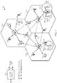
- FIG. 1 illustrates an example wireless network 100, such as a new radio (NR) or 5G network, in which aspects of the present disclosure may be performed, for example, for control channel rate code selection.
- NR new radio
- 5G 5th Generation
- the wireless network 100 may include a number of BSs 110 and other network entities.
- a BS may be a station that communicates with UEs.
- Each BS 110 may provide communication coverage for a particular geographic area.
- the term "cell" can refer to a coverage area of a Node B and/or a Node B subsystem serving this coverage area, depending on the context in which the term is used.
- the term "cell” and eNB, Node B, 5G NB, AP, NR BS, NR BS, gNB, or TRP may be interchangeable.
- a cell may not necessarily be stationary, and the geographic area of the cell may move according to the location of a mobile base station.
- the base stations may be interconnected to one another and/or to one or more other base stations or network nodes (not shown) in the wireless network 100 through various types of backhaul interfaces such as a direct physical connection, a virtual network, or the like using any suitable transport network.
- any number of wireless networks may be deployed in a given geographic area.
- Each wireless network may support a particular radio access technology (RAT) and may operate on one or more frequencies.
- a RAT may also be referred to as a radio technology, an air interface, etc.
- a frequency may also be referred to as a carrier, a frequency channel, etc.
- Each frequency may support a single RAT in a given geographic area in order to avoid interference between wireless networks of different RATs.
- NR or 5G RAT networks may be deployed, employing a multi-slice network architecture.
- a BS may provide communication coverage for a macro cell, a pico cell, a femto cell, and/or other types of cell.
- a macro cell may cover a relatively large geographic area (e.g., several kilometers in radius) and may allow unrestricted access by UEs with service subscription.
- a pico cell may cover a relatively small geographic area and may allow unrestricted access by UEs with service subscription.
- a femto cell may cover a relatively small geographic area (e.g., a home) and may allow restricted access by UEs having association with the femto cell (e.g., UEs in a Closed Subscriber Group (CSG), UEs for users in the home, etc.).
- CSG Closed Subscriber Group
- a BS for a macro cell may be referred to as a macro BS.
- a BS for a pico cell may be referred to as a pico BS.
- a BS for a femto cell may be referred to as a femto BS or a home BS.
- the BSs 110a, 110b and 110c may be macro BSs for the macro cells 102a, 102b and 102c, respectively.
- the BS 110x may be a pico BS for a pico cell 102x.
- the BSs 110y and 110z may be femto BS for the femto cells 102y and 102z, respectively.
- a BS may support one or multiple (e.g., three) cells.
- the wireless network 100 may also include relay stations.
- a relay station is a station that receives a transmission of data and/or other information from an upstream station (e.g., a BS or a UE) and sends a transmission of the data and/or other information to a downstream station (e.g., a UE or a BS).
- a relay station may also be a UE that relays transmissions for other UEs.
- a relay station 110r may communicate with the BS 110a and a UE 120r in order to facilitate communication between the BS 110a and the UE 120r.
- a relay station may also be referred to as a relay BS, a relay, etc.
- the wireless network 100 may be a heterogeneous network that includes BSs of different types, e.g., macro BS, pico BS, femto BS, relays, etc. These different types of BSs may have different transmit power levels, different coverage areas, and different impact on interference in the wireless network 100.
- macro BS may have a high transmit power level (e.g., 20 Watts) whereas pico BS, femto BS, and relays may have a lower transmit power level (e.g., 1 Watt).
- the wireless network 100 may support synchronous or asynchronous operation.
- the BSs may have similar frame timing, and transmissions from different BSs may be approximately aligned in time.
- the BSs may have different frame timing, and transmissions from different BSs may not be aligned in time.
- the techniques described herein may be used for both synchronous and asynchronous operation.
- a network controller 130 may couple to a set of BSs and provide coordination and control for these BSs.
- the network controller 130 may communicate with the BSs 110 via a backhaul.
- the BSs 110 may also communicate with one another, e.g., directly or indirectly via wireless or wireline backhaul.
- the UEs 120 may be dispersed throughout the wireless network 100, and each UE may be stationary or mobile.
- a UE may also be referred to as a mobile station, a terminal, an access terminal, a subscriber unit, a station, a Customer Premises Equipment (CPE), a cellular phone, a smart phone, a personal digital assistant (PDA), a wireless modem, a wireless communication device, a handheld device, a laptop computer, a cordless phone, a wireless local loop (WLL) station, a tablet, a camera, a gaming device, a netbook, a smartbook, an ultrabook, a medical device or medical equipment, a biometric sensor/device, a wearable device such as a smart watch, smart clothing, smart glasses, a smart wrist band, smart jewelry (e.g., a smart ring, a smart bracelet, etc.), an entertainment device (e.g., a music device, a video device, a
- CPE Customer Premises Equipment
- Some UEs may be considered evolved or machine-type communication (MTC) devices or evolved MTC (eMTC) devices.
- MTC and eMTC UEs include, for example, robots, drones, remote devices, sensors, meters, monitors, location tags, etc., that may communicate with a BS, another device (e.g., remote device), or some other entity.
- a wireless node may provide, for example, connectivity for or to a network (e.g., a wide area network such as Internet or a cellular network) via a wired or wireless communication link.
- Some UEs may be considered Internet-of-Things (IoT) devices.
- IoT Internet-of-Things
- a solid line with double arrows indicates desired transmissions between a UE and a serving BS, which is a BS designated to serve the UE on the downlink and/or uplink.
- a dashed line with double arrows indicates interfering transmissions between a UE and a BS.
- Certain wireless networks utilize orthogonal frequency division multiplexing (OFDM) on the downlink and single-carrier frequency division multiplexing (SC-FDM) on the uplink.
- OFDM and SC-FDM partition the system bandwidth into multiple (K) orthogonal subcarriers, which are also commonly referred to as tones, bins, etc.
- K orthogonal subcarriers
- Each subcarrier may be modulated with data.
- modulation symbols are sent in the frequency domain with OFDM and in the time domain with SC-FDM.
- the spacing between adjacent subcarriers may be fixed, and the total number of subcarriers (K) may be dependent on the system bandwidth.
- the spacing of the subcarriers may be 15 kHz and the minimum resource allocation (called a 'resource block') may be 12 subcarriers (or 180 kHz). Consequently, the nominal FFT size may be equal to 128, 256, 512, 1024 or 2048 for system bandwidth of 1.25, 2.5, 5, 10 or 20 megahertz (MHz), respectively.
- the system bandwidth may also be partitioned into subbands. For example, a subband may cover 1.08 MHz (i.e., 6 resource blocks), and there may be 1, 2, 4, 8 or 16 subbands for system bandwidth of 1.25, 2.5, 5, 10 or 20 MHz, respectively.
- NR may utilize OFDM with a CP on the uplink and downlink and include support for half-duplex operation using TDD.
- a single component carrier bandwidth of 100 MHz may be supported.
- NR resource blocks may span 12 sub-carriers with a subcarrier bandwidth of 75 kHz over a 0.1ms duration.
- Each radio frame may consist of 50 subframes with a length of 10ms. Consequently, each subframe may have a length of 0.2ms.
- Each subframe may indicate a link direction (i.e., DL or UL) for data transmission and the link direction for each subframe may be dynamically switched.
- Each subframe may include DL/UL data as well as DL/UL control data.
- UL and DL subframes for NR may be as described in more detail below with respect to FIGs. 6 and 7 .
- Beamforming may be supported and beam direction may be dynamically configured.
- MIMO transmissions with precoding may also be supported.
- MIMO configurations in the DL may support up to 8 transmit antennas with multi-layer DL transmissions up to 8 streams and up to 2 streams per UE.
- Multi-layer transmissions with up to 2 streams per UE may be supported.
- Aggregation of multiple cells may be supported with up to 8 serving cells.
- NR may support a different air interface, other than an OFDM-based.
- NR networks may include entities such CUs and/or one or more DUs.
- a scheduling entity e.g., a base station
- the scheduling entity may be responsible for scheduling, assigning, reconfiguring, and releasing resources for one or more subordinate entities. That is, for scheduled communication, subordinate entities utilize resources allocated by the scheduling entity.
- Base stations are not the only entities that may function as a scheduling entity. That is, in some examples, a UE may function as a scheduling entity, scheduling resources for one or more subordinate entities (e.g., one or more other UEs).
- the UE is functioning as a scheduling entity, and other UEs utilize resources scheduled by the UE for wireless communication.
- a UE may function as a scheduling entity in a peer-to-peer (P2P) network, and/or in a mesh network.
- P2P peer-to-peer
- UEs may optionally communicate directly with one another in addition to communicating with the scheduling entity.
- a scheduling entity and one or more subordinate entities may communicate utilizing the scheduled resources.
- a RAN may include a CU and one or more DUs.
- a NR BS e.g., gNB, 5G Node B, Node B, transmission reception point (TRP), access point (AP)
- NR cells can be configured as access cell (ACells) or data only cells (DCells).
- the RAN e.g., a central unit or distributed unit
- DCells may be cells used for carrier aggregation or dual connectivity, but not used for initial access, cell selection/reselection, or handover. In some cases DCells may not transmit synchronization signals-in some case cases DCells may transmit SS.
- NR BSs may transmit downlink signals to UEs indicating the cell type. Based on the cell type indication, the UE may communicate with the NR BS. For example, the UE may determine NR BSs to consider for cell selection, access, handover, and/or measurement based on the indicated cell type.
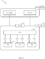
- FIG. 2 illustrates an example logical architecture of a distributed radio access network (RAN) 200, which may be implemented in the wireless communication system illustrated in FIG. 1 .
- a 5G access node 206 may include an access node controller (ANC) 202.
- the ANC may be a central unit (CU) of the distributed RAN 200.
- the backhaul interface to the next generation core network (NG-CN) 204 may terminate at the ANC.
- the backhaul interface to neighboring next generation access nodes (NG-ANs) may terminate at the ANC.
- the ANC may include one or more TRPs 208 (which may also be referred to as BSs, NR BSs, Node Bs, 5G NBs, APs, gNB, or some other term).
- TRP may be used interchangeably with "cell” and may refer to a region where a same set of radio resources are available throughout the region.
- the TRPs 208 may be a DU.
- the TRPs may be connected to one ANC (ANC 202) or more than one ANC (not illustrated).
- ANC ANC
- RaaS radio as a service
- a TRP may include one or more antenna ports.
- the TRPs may be configured to individually (e.g., dynamic selection) or jointly (e.g., joint transmission) serve traffic to a UE.
- the logical architecture of a distributed RAN 200 may be used to illustrate fronthaul definition.
- the architecture may be defined that support fronthauling solutions across different deployment types.
- the architecture may be based on transmit network capabilities (e.g., bandwidth, latency, and/or jitter).
- the architecture may share features and/or components with LTE.
- the next generation AN (NG-AN) 210 may support dual connectivity with NR.
- the NG-AN may share a common fronthaul for LTE and NR.
- the architecture may enable cooperation between and among TRPs 208. For example, cooperation may be preset within a TRP and/or across TRPs via the ANC 202. According to aspects, no inter-TRP interface may be needed/present.
- a dynamic configuration of split logical functions may be present within the architecture 200.
- the Radio Resource Control (RRC) layer, Packet Data Convergence Protocol (PDCP) layer, Radio Link Control (RLC) layer, Medium Access Control (MAC) layer, and a Physical (PHY) layers may be adaptably placed at the DU or CU (e.g., TRP or ANC, respectively).
- a BS may include a central unit (CU) (e.g., ANC 202) and/or one or more distributed units (e.g., one or more TRPs 208).
- CU central unit
- distributed units e.g., one or more TRPs 208.
- FIG. 3 illustrates an example physical architecture of a distributed RAN 300, according to aspects of the present disclosure.
- a centralized core network unit (C-CU) 302 may host core network functions.
- the C-CU may be centrally deployed.
- C-CU functionality may be offloaded (e.g., to advanced wireless services (AWS)), in an effort to handle peak capacity.
- AWS advanced wireless services
- a centralized RAN unit (C-RU) 304 may host one or more ANC functions.
- the C-RU may host core network functions locally.
- the C-RU may have distributed deployment.
- the C-RU may be closer to the network edge.
- a DU 306 may host one or more TRPs (edge node (EN), an edge unit (EU), a radio head (RH), a smart radio head (SRH), or the like).
- the DU may be located at edges of the network with radio frequency (RF) functionality.
- RF radio frequency
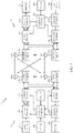
- FIG. 4 illustrates example components of the BS 110 and UE 120 illustrated in FIG. 1 , which may be used to implement aspects of the present disclosure.
- the BS may include a TRP.
- One or more components of the BS 110 and UE 120 may be used to practice aspects of the present disclosure.
- antennas 452, Tx/Rx 222, processors 466, 458, 464, and/or controller/processor 480 of the UE 120 and/or antennas 434, processors 460, 420, 438, and/or controller/processor 440 of the BS 110 may be used to perform the operations described herein and illustrated with reference to FIGs. 8A-8B.
- the base station 110 may be the macro BS 110c in FIG. 1 , and the UE 120 may be the UE 120y.
- the base station 110 may also be a base station of some other type.
- the base station 110 may be equipped with antennas 434a through 434t, and the UE 120 may be equipped with antennas 452a through 452r.
- a transmit processor 420 may receive data from a data source 412 and control information from a controller/processor 440.
- the control information may be for the Physical Broadcast Channel (PBCH), Physical Control Format Indicator Channel (PCFICH), Physical Hybrid ARQ Indicator Channel (PHICH), Physical Downlink Control Channel (PDCCH), etc.
- the data may be for the Physical Downlink Shared Channel (PDSCH), etc.
- the processor 420 may process (e.g., encode and symbol map) the data and control information to obtain data symbols and control symbols, respectively.
- the processor 420 may also generate reference symbols, e.g., for the PSS, SSS, and cell-specific reference signal.
- a transmit (TX) multiple-input multiple-output (MIMO) processor 430 may perform spatial processing (e.g., precoding) on the data symbols, the control symbols, and/or the reference symbols, if applicable, and may provide output symbol streams to the modulators (MODs) 432a through 432t.
- Each modulator 432 may process a respective output symbol stream (e.g., for OFDM, etc.) to obtain an output sample stream.
- Each modulator 432 may further process (e.g., convert to analog, amplify, filter, and upconvert) the output sample stream to obtain a downlink signal.
- Downlink signals from modulators 432a through 432t may be transmitted via the antennas 434a through 434t, respectively.
- the antennas 452a through 452r may receive the downlink signals from the base station 110 and may provide received signals to the demodulators (DEMODs) 454a through 454r, respectively.
- Each demodulator 454 may condition (e.g., filter, amplify, downconvert, and digitize) a respective received signal to obtain input samples.
- Each demodulator 454 may further process the input samples (e.g., for OFDM, etc.) to obtain received symbols.
- a MIMO detector 456 may obtain received symbols from all the demodulators 454a through 454r, perform MIMO detection on the received symbols if applicable, and provide detected symbols.
- a receive processor 458 may process (e.g., demodulate, deinterleave, and decode) the detected symbols, provide decoded data for the UE 120 to a data sink 460, and provide decoded control information to a controller/processor 480.
- a transmit processor 464 may receive and process data (e.g., for the Physical Uplink Shared Channel (PUSCH)) from a data source 462 and control information (e.g., for the Physical Uplink Control Channel (PUCCH) from the controller/processor 480.
- the transmit processor 464 may also generate reference symbols for a reference signal.
- the symbols from the transmit processor 464 may be precoded by a TX MIMO processor 466 if applicable, further processed by the demodulators 454a through 454r (e.g., for SC-FDM, etc.), and transmitted to the base station 110.
- the uplink signals from the UE 120 may be received by the antennas 434, processed by the modulators 432, detected by a MIMO detector 436 if applicable, and further processed by a receive processor 438 to obtain decoded data and control information sent by the UE 120.
- the receive processor 438 may provide the decoded data to a data sink 439 and the decoded control information to the controller/processor 440.
- the controllers/processors 440 and 480 may direct the operation at the base station 110 and the UE 120, respectively.
- the processor 440 and/or other processors and modules at the base station 110 may perform or direct, e.g., the execution of the functional blocks illustrated in FIG. 12 , and/or other processes for the techniques described herein.
- the processor 480 and/or other processors and modules at the UE 120 may also perform or direct, e.g., the execution of the functional blocks illustrated in FIG. 8 and/or 11, and/or other processes for the techniques described herein.
- the memories 442 and 482 may store data and program codes for the BS 110 and the UE 120, respectively.
- a scheduler 444 may schedule UEs for data transmission on the downlink and/or uplink.
- FIG. 5 illustrates a diagram 500 showing examples for implementing a communications protocol stack, according to aspects of the present disclosure.
- the illustrated communications protocol stacks may be implemented by devices operating in a in a 5G system (e.g., a system that supports uplink-based mobility).
- Diagram 500 illustrates a communications protocol stack including a Radio Resource Control (RRC) layer 510, a Packet Data Convergence Protocol (PDCP) layer 515, a Radio Link Control (RLC) layer 520, a Medium Access Control (MAC) layer 525, and a Physical (PHY) layer 530.
- RRC Radio Resource Control
- PDCP Packet Data Convergence Protocol
- RLC Radio Link Control
- MAC Medium Access Control
- PHY Physical
- the layers of a protocol stack may be implemented as separate modules of software, portions of a processor or ASIC, portions of non-collocated devices connected by a communications link, or various combinations thereof. Collocated and non-collocated implementations may be used, for example, in a protocol stack for a network access device (e.g., ANs, CUs, and/or one or more DUs) or a UE.
- a network access device e.g., ANs, CUs, and/or one or more DUs
- a first option 505-a shows a split implementation of a protocol stack, in which implementation of the protocol stack is split between a centralized network access device (e.g., an ANC 202 in FIG. 2 ) and distributed network access device (e.g., DU 208 in FIG. 2 ).
- a centralized network access device e.g., an ANC 202 in FIG. 2
- distributed network access device e.g., DU 208 in FIG. 2
- an RRC layer 510 and a PDCP layer 515 may be implemented by the central unit
- an RLC layer 520, a MAC layer 525, and a PHY layer 530 may be implemented by the DU.
- the CU and the DU may be collocated or non-collocated.
- the first option 505-a may be useful in a macro cell, micro cell, or pico cell deployment.
- a second option 505-b shows a unified implementation of a protocol stack, in which the protocol stack is implemented in a single network access device (e.g., access node (AN), new radio base station (NR BS), a new radio Node-B (NR NB), a network node (NN), or the like.).
- the RRC layer 510, the PDCP layer 515, the RLC layer 520, the MAC layer 525, and the PHY layer 530 may each be implemented by the AN.
- the second option 505-b may be useful in a femto cell deployment.
- a UE may implement an entire protocol stack (e.g., the RRC layer 510, the PDCP layer 515, the RLC layer 520, the MAC layer 525, and the PHY layer 530).
- an entire protocol stack e.g., the RRC layer 510, the PDCP layer 515, the RLC layer 520, the MAC layer 525, and the PHY layer 530.
- FIG. 6 illustrates various components that may be utilized in a wireless communications device 602 that may be employed within the wireless communication system from FIG. 1 .
- the wireless communications device 602 is an example of a device that may be configured to implement the various methods described herein.
- the wireless communications device 602 may be an BS 110 from FIG. 1 or any of user equipments 120.
- the wireless communications device 602 may include a processor 604 which controls operation of the wireless communications device 602.
- the processor 604 may also be referred to as a central processing unit (CPU).
- Memory 606 which may include both read-only memory (ROM) and random access memory (RAM), provides instructions and data to the processor 604.
- a portion of the memory 606 may also include non-volatile random access memory (NVRAM).
- the processor 604 typically performs logical and arithmetic operations based on program instructions stored within the memory 606.
- the instructions in the memory 606 may be executable to implement the methods described herein.
- the wireless communications device 602 may also include a housing 608 that may include a transmitter 610 and a receiver 612 to allow transmission and reception of data between the wireless communications device 602 and a remote location.
- the transmitter 610 and receiver 612 may be combined into a transceiver 614.
- a single or a plurality of transmit antennas 616 may be attached to the housing 608 and electrically coupled to the transceiver 614.
- the wireless communications device 602 may also include (not shown) multiple transmitters, multiple receivers, and multiple transceivers.
- the wireless communications device 602 may also include a signal detector 618 that may be used in an effort to detect and quantify the level of signals received by the transceiver 614.
- the signal detector 618 may detect such signals as total energy, energy per subcarrier per symbol, power spectral density and other signals.
- the wireless communications device 602 may also include a digital signal processor (DSP) 620 for use in processing signals.
- DSP digital signal processor
- the wireless communications device 602 may also include an encoder 622 for use in encoding signals for transmission.
- the encoder may select a rate code to encode the signals and may store the encoded signals in a circular buffer (not shown).
- the encoder may also perform rate matching on the encoded signals, as described below.
- the wireless communications device 602 may include a decoder 624 for use in decoding received signals, for example, by selecting a rate code to decode the received signals.
- the various components of the wireless communications device 602 may be coupled together by a bus system 626, which may include a power bus, a control signal bus, and a status signal bus in addition to a data bus.
- the processor 604 may be configured to access instructions stored in the memory 606 to perform connectionless access, in accordance with aspects of the present disclosure discussed below.
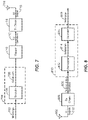
- FIG. 7 is a simplified block diagram illustrating an encoder, in accordance with certain aspects of the present disclosure.
- FIG. 7 illustrates a portion of a radio frequency (RF) modem 704 that may be configured to provide an encoded message for wireless transmission (e.g., using polar codes described below).
- RF radio frequency
- an encoder 706 in a base station e.g., BS 110
- the message 702 may contain data and/or encoded voice or other content directed to the receiving device.
- the encoder 706 encodes the message using a suitable modulation and coding scheme (MCS), typically selected based on a configuration defined by the BS 110 or another network entity.
- MCS modulation and coding scheme
- the encoder 706 may select, from a set of rate codes, a rate code to be used to encode the message.
- the encoded bitstream 708 may then be stored in circular buffer and rate-matching may be performed on the stored encoded bitstream, for example, according to aspects presented below.
- the encoded bitstream 708 may then be provided to a mapper 710 that generates a sequence of Tx symbols 712 that are modulated, amplified and otherwise processed by Tx chain 714 to produce an RF signal 716 for transmission through antenna 718.
- FIG. 8 is a simplified block diagram illustrating a decoder, in accordance with certain aspects of the present disclosure.
- FIG. 8 illustrates a portion of a RF modem 810 that may be configured to receive and decode a wirelessly transmitted signal including an encoded message (e.g., a message encoded using techniques presented herein).
- the modem 810 receiving the signal may reside at the access terminal, at the base station, or at any other suitable apparatus or means for carrying out the described functions.
- An antenna 802 provides an RF signal 716 (i.e., the RF signal produced in FIG. 4 ) to an access terminal (e.g., UE 120).
- An Rx chain 806 processes and demodulates the RF signal 716 and may provide a sequence of symbols 808 to a demapper 812, which produces a sequence of a-priori probabilities (e.g., in bitstream 814), often represented as log-likelihood ratios (LLRs) corresponding to the encoded message.
- a-priori probabilities e.g., in bitstream 814
- LLRs log-likelihood ratios
- a decoder 816 may then be used to decode m-bit information strings from a bitstream that has been encoded using a coding scheme (e.g., as described herein).
- the decoder 816 may comprise a polar decoder, an LDPC decoder, a Viterbi decoder, an algebraic decoder, a butterfly decoder, or another suitable decoder.
- a Polar decoder employs the successive cancellation (SC) or successive cancellation list (SCL) decoding algorithm.
- An SC decoding algorithm essentially operates by performing a recursive depth-first traversal of a decoding tree, to convert the sequence of LLRs (e.g., in bitstream 814) into a bit sequence/message 818 corresponding to the message 702 (e.g., when the decoding is successful).
- the root of the tree corresponds to the received vector of N log likelihood ratios (LLRs) to be decoded, and the leaves of the tree correspond to each of the decoded bits, so that N-K of the leaves correspond to the N-K frozen bits (which should decode to the frozen value (zero)), while the remaining K leaves correspond to the K information bits.
- LLRs log likelihood ratios
- converting the 2 d LLRs corresponding to any node v into the 2 d decoded bits corresponding to the 2 d leaves of that node is performed via a recursive depth-first traversal of the decoding tree, as follows.
- the decoder 816 may first use the 2 d LLRs corresponding to this node v to calculate the 2 d-1 LLRs corresponding to node v's left child.
- the decoder 816 may then decode the subcode corresponding to node v's left child.
- the decoder 816 may then re-encode the length 2 d-1 codeword corresponding to the left child.
- This partial codeword is referred to as a (left) partial sum.
- the decoder 816 may then use the partial sum from node v's left child along with the 2 d LLRs corresponding to node v to calculate the 2 d-1 LLRs corresponding to v's right child. Thereafter, the decoder 816 may decode the subcode corresponding to node v's right child. Additionally, the decoder 816 may re-encode the length 2 d codeword corresponding to the right child and this partial codeword is referred to as a (right) partial sum. Thereafter, the decoder 816 may combine the left and right partial sums to get the partial sum (codeword) corresponding to v.
- the above decoding algorithm may include combining LLRs associated with lower aggregation levels with LLRs associated with higher aggregation levels and use the combined LLRs to decode the bitstream 814, for example, as described in greater detail below.
- FIG. 9 is a diagram 900 showing an example of a DL-centric subframe, which may be used by one or more devices (e.g., BS 110 and/or UE 120) to communicate in the wireless network 100.
- the DL-centric subframe may include a control portion 902.
- the control portion 902 may exist in the initial or beginning portion of the DL-centric subframe.
- the control portion 902 may include various scheduling information and/or control information corresponding to various portions of the DL-centric subframe.
- the control portion 902 may be a physical DL control channel (PDCCH), as indicated in FIG. 9 .
- the DL-centric subframe may also include a DL data portion 904.
- the DL data portion 904 may sometimes be referred to as the payload of the DL-centric subframe.
- the DL data portion 904 may include the communication resources utilized to communicate DL data from the scheduling entity (e.g., UE or BS) to the subordinate entity (e.g., UE).
- the DL data portion 904 may be a physical DL shared channel (PDSCH).
- PDSCH physical DL shared channel
- the DL-centric subframe may also include a common UL portion 906.
- the common UL portion 906 may sometimes be referred to as an UL burst, a common UL burst, and/or various other suitable terms.
- the common UL portion 906 may include feedback information corresponding to various other portions of the DL-centric subframe.
- the common UL portion 906 may include feedback information corresponding to the control portion 902.
- Non-limiting examples of feedback information may include an ACK signal, a NACK signal, a HARQ indicator, and/or various other suitable types of information.
- the common UL portion 906 may include additional or alternative information, such as information pertaining to random access channel (RACH) procedures, scheduling requests (SRs), and various other suitable types of information.
- RACH random access channel
- SRs scheduling requests
- the end of the DL data portion 904 may be separated in time from the beginning of the common UL portion 906.
- This time separation may sometimes be referred to as a gap, a guard period, a guard interval, and/or various other suitable terms.
- This separation provides time for the switch-over from DL communication (e.g., reception operation by the subordinate entity (e.g., UE)) to UL communication (e.g., transmission by the subordinate entity (e.g., UE)).
- DL communication e.g., reception operation by the subordinate entity (e.g., UE)
- UL communication e.g., transmission by the subordinate entity (e.g., UE)
- FIG. 10 is a diagram 1000 showing an example of an UL-centric subframe, which may be used by one or more devices (e.g., BS 110 and/or UE 120) to communicate in the wireless network 100.
- the UL -centric subframe may include a control portion 1002.
- the control portion 1002 may exist in the initial or beginning portion of the UL-centric subframe.
- the control portion 1002 in FIG. 10 may be similar to the control portion described above with reference to FIG. 9 .
- the UL-centric subframe may also include an UL data portion 1004.
- the UL data portion 1004 may sometimes be referred to as the payload of the UL-centric subframe.
- the UL portion may refer to the communication resources utilized to communicate UL data from the subordinate entity (e.g., UE) to the scheduling entity (e.g., UE or BS).
- the control portion 1002 may be a physical DL control channel (PDCCH).
- the end of the control portion 1002 may be separated in time from the beginning of the UL data portion 1004. This time separation may sometimes be referred to as a gap, guard period, guard interval, and/or various other suitable terms. This separation provides time for the switch-over from DL communication (e.g., reception operation by the scheduling entity) to UL communication (e.g., transmission by the scheduling entity).
- the UL-centric subframe may also include a common UL portion 1006.
- the common UL portion 1006 in FIG. 10 may be similar to the common UL portion 1006 described above with reference to FIG. 10 .
- the common UL portion 1006 may additional or alternative include information pertaining to channel quality indicator (CQI), sounding reference signals (SRSs), and various other suitable types of information.
- CQI channel quality indicator
- SRSs sounding reference signals
- One of ordinary skill in the art will understand that the foregoing is merely one example of an UL-centric subframe and alternative structures having similar features may exist without necessarily deviating from the aspects described herein.
- two or more subordinate entities may communicate with each other using sidelink signals.
- Real-world applications of such sidelink communications may include public safety, proximity services, UE-to-network relaying, vehicle-to-vehicle (V2V) communications, Internet of Everything (IoE) communications, IoT communications, mission-critical mesh, and/or various other suitable applications.
- a sidelink signal may refer to a signal communicated from one subordinate entity (e.g., UE1) to another subordinate entity (e.g., UE2) without relaying that communication through the scheduling entity (e.g., UE or BS), even though the scheduling entity may be utilized for scheduling and/or control purposes.
- the sidelink signals may be communicated using a licensed spectrum (unlike wireless local area networks, which typically use an unlicensed spectrum).
- a UE may operate in various radio resource configurations, including a configuration associated with transmitting pilots using a dedicated set of resources (e.g., a radio resource control (RRC) dedicated state, etc.) or a configuration associated with transmitting pilots using a common set of resources (e.g., an RRC common state, etc.).
- RRC radio resource control
- the UE may select a dedicated set of resources for transmitting a pilot signal to a network.
- the UE may select a common set of resources for transmitting a pilot signal to the network.
- a pilot signal transmitted by the UE may be received by one or more network access devices, such as an AN, or a DU, or portions thereof.
- Each receiving network access device may be configured to receive and measure pilot signals transmitted on the common set of resources, and also receive and measure pilot signals transmitted on dedicated sets of resources allocated to the UEs for which the network access device is a member of a monitoring set of network access devices for the UE.
- One or more of the receiving network access devices, or a CU to which receiving network access device(s) transmit the measurements of the pilot signals may use the measurements to identify serving cells for the UEs, or to initiate a change of serving cell for one or more of the UEs.
- Polar codes are a relatively recent breakthrough in coding theory which have been proven to asymptotically (for code size N approaching infinity) achieve the Shannon capacity.
- Polar codes have many desirable properties such as deterministic construction (e.g., based on a fast Hadamard transform), very low and predictable error floors, and simple successive-cancellation (SC) based decoding. They are currently being considered as a candidate for error-correction in next-generation wireless systems, and will be used for control channel encoding in 5G.
- every estimated bit, û i has a predetermined error probability given that bits u 0 i-1 were correctly decoded, that, for extremely large codesize N, tends towards either 0 or 0.5. Moreover, the proportion of estimated bits with a low error probability tends towards the capacity of the underlying channel.
- Polar codes exploit this phenomenon, called channel polarization, by using the most reliable K bits to transmit information, while setting to a predetermined value (such as 0), also referred to as freezing, the remaining (N-K) bits, for example as explained below.
- Polar codes transform the channel into N parallel "virtual" channels for the N information and frozen bits. If C is the capacity of the channel, then, for sufficiently large values of N, there are almost NC channels which are extremely reliable and there are almost N(1 - C) channels which are extremely unreliable.
- the basic polar coding scheme then involves freezing (i.e., setting to a known value, such as zero) the input bits in u corresponding to the unreliable channels, while placing information bits only in the bits of u corresponding to reliable channels. For short-to-medium N, this polarization may not be complete in the sense there could be several channels which are neither completely unreliable nor completely reliable (i.e., channels that are marginally reliable). Depending on the rate of transmission, bits corresponding to these marginally reliable channels may be either frozen or used for information bits.
- tail-biting convolutional codes of code rate 1/3 are used as a baseline code for the encoding information sent on downlink (DL) control channels.
- DCI downlink control information
- different code rates which may be realized by rate matching from the baseline code, through either puncturing or repeating coded bits. That is, after encoding information using a 1/3 TBCC, the encoded information's code rate may be adjusted using rate matching (e.g., puncturing and/or repetition) before transmission.
- Polar codes may be used to encode information transmitted on DL control channels.
- a single baseline code rate baseline for Polar codes e.g similar to 1/3 TBCC
- aspects of the present disclosure present techniques for selecting, from a set of baseline code rates, a code rate for encoding information using a polar code.
- selecting a code rate may be based on a control channel aggregation level and/or a payload size of a stream of bits to be encoded using a Polar code.
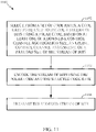
- FIG. 11 illustrates example operations 1100 for wireless communications. Operations 1100 may be performed by a wireless communications device, such as a base station (BS 110), user equipment 120, and/or wireless communications device 602.
- a wireless communications device such as a base station (BS 110), user equipment 120, and/or wireless communications device 602.
- the wireless communications device may include one or more components as illustrated in FIGs. 4 and/or 6 which may be configured to perform the operations described herein.
- the antenna 434, modulator/demodulator 432, transmit processor 420, controller/processor 440, and/or memory 442 of the base station 110, as illustrated in FIG. 4 may perform the operations described herein.
- the antenna 452, demodulator/modulator 454, transmit processor 464, controller/processor 480, and/or memory 482 of the user equipment 120, as illustrated in FIG. 4 may perform the operations described herein.
- processor 604, memory 606, transceiver 614, DSP 320, encoder 622, decoder 620, and/or antenna(s) 616 as illustrated in FIG. 6 may be configured to perform the operations described herein.
- Operations 1100 begin at 1102 by selecting, from a set of code rates, a code rate to be used to encode a stream of bits using a polar code, based on at least one of a downlink control channel aggregation level, an uplink control channel assignment size, or a payload size of the stream of bits.
- the wireless communications device encodes the stream of bits using the polar code and the selected code rate.
- the wireless communications device transmits the encoded stream of bits, for example, using one or antennas.
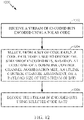
- FIG. 12 illustrates example operations 1200 for wireless communications. Operations 1200 may be performed by a wireless communications device, such as a base station (BS 110), user equipment 120, and/or wireless communications device 602.
- a wireless communications device such as a base station (BS 110), user equipment 120, and/or wireless communications device 602.
- the wireless communications device may include one or more components as illustrated in FIGs. 4 and/or 6 which may be configured to perform the operations described herein.
- the antenna 434, modulator/demodulator 432, transmit processor 420, controller/processor 440, and/or memory 442 of the base station 110, as illustrated in FIG. 4 may perform the operations described herein.
- the antenna 452, demodulator/modulator 454, transmit processor 464, controller/processor 480, and/or memory 482 of the user equipment 120, as illustrated in FIG. 4 may perform the operations described herein.
- processor 604, memory 606, transceiver 614, DSP 320, encoder 622, decoder 620, and/or antenna(s) 616 as illustrated in FIG. 6 may be configured to perform the operations described herein.
- Operations 1200 begin at 1202 by receiving a stream of encoded bits encoded using a polar code.
- the wireless communications device selects, from a set of code rates, a code rate to be used to decode the stream of encoded bits, based on at least one of a downlink control channel aggregation level, an uplink control channel assignment size, or a payload size of the stream of bits.
- the wireless communications device decodes the stream of encoded bits using selected code rate.
- aspects of the present disclosure propose techniques for selecting, from a set of baseline code rates, a code rate for encoding information using a polar code.
- a wireless communications device may select between X baseline Polar code rates to be used to encode a stream of bits for transmission on a control channel (e.g., a physical downlink control channel (PDCCH), a physical uplink control channel (PUCCH), etc.), where X >1.
- a control channel e.g., a physical downlink control channel (PDCCH), a physical uplink control channel (PUCCH), etc.
- X e.g., a physical downlink control channel (PDCCH), a physical uplink control channel (PUCCH), etc.
- X should not be very large.
- the wireless communications device selects the code rate based on at least one of a payload size of the stream of bits to be transmitted on the downlink control channel or an aggregation level of the downlink control channel (e.g., the number of control channel elements used for sending control information). For example, a control message may be transmitted at aggregation level, L, if L CCEs are used to convey the message.
- the wireless communications device may use a first polar code rate (PC1), whereas a second polar code rate (PC2) may be used for an aggregation level of 1 or 2 with a payload size less than 50 bits.
- PC1 first polar code rate
- PC2 second polar code rate
- selecting the code rate in this manner i.e., based on the aggregation level and/or payload size) allows for more efficient use of resources (e.g., bandwidth resources) and communication because it control the balance between coding gain and coding/decoding complexity.
- the wireless communications device selects the code rate based on at least one of an assignment size of the uplink control channel (e.g., as indicated in downlink control channel information carrying an uplink grant) or a payload size of the stream of bits to be transmitted on the uplink control channel (e.g., .
- the assignment size of the uplink control channel may be defined as a number of resource elements and/or a number of resource blocks assigned to the uplink control channel.
- uplink control channels e.g., PUCCH
- a longer duration means more REs for the uplink control channel, which may be treated as a larger uplink control channel assignment.
- the selection of a code rate for an uplink control channel may also be based on the duration of the uplink control channel.
- the wireless communications device e.g., a UE
- the wireless communications device may store the encoded stream of bits in a circular buffer and does perform rate-matching on the stored encoded bits.
- Rate matching is a process whereby the number of bits to be transmitted is matched to the available bandwidth of the number of bits allowed to be transmitted.
- the amount of data to be transmitted is less than the available bandwidth, in which case all the data to be transmitted (and one or more copies of the data) will be transmitted - a technique called repetition.
- the amount of data to be transmitted exceeds the available bandwidth, in which case a certain portion of the data to be transmitted will be omitted from the transmission, for example, using techniques known as puncturing and shortening.
- puncturing, shortening, or repetition of bits stored in the circular buffer may be performed according to a puncturing, shortening, or repetition pattern, respectively.
- this pattern may be a function of the selected rate code.
- a pattern indicating which bits in the circular buffer are to be punctured, shortened, and/or repeated, may be determined. For example, assuming that the wireless communication device has chosen a polar code rate, PC1, having rate 1/3 for a given Payload Size of 40 bits and aggregation level of 4 which requires a rate R>.4, the wireless communications device may use a puncturing pattern specific to PC1 to rate match to rate R (i.e., 0.4).
- puncturing, shortening, and/or repetition may be performed by reading from the circular buffer the encoded steam of bits, and the puncture-pattern determined by interleaving performed on the encoded stream of bits prior to populating the circular buffer.
- the interleaver could be chosen as a function of the chosen Polar code rate.
- the selected code rate e.g., to generate a codeword.
- the wireless communications device may store the "native" encoded stream of bits (e.g., native-sized encoded stream of bits) in a circular buffer and perform rate-matching on the stored native encoded stream of bits, as described above.
- decoding complexity scales super-linearly as the size of the polar code/number of coded bits, N, increases. Further, for any fixed control information size, K, the coding gain obtained from extending to a lower native code-rate diminishes as N increases.
- extending a native code rate from 1/3 to 1/6 may yield a noticeable gain compared with using the native rate 1/3 code with repetition to get rate 1/6
- extending a native rate from 1/6 to 1/12 may yield a small gain compared with using a native rate 1/6 code with repetition to get rate 1/12.
- the allowed code rate is very low (e.g., below rate 1/6)
- a higher rate code may be selected by the wireless communication device and repetition performed to extend to lower rate with reduced complexity and similar performance.
- rate matching is needed since native polar codes only support 2n coded bits.
- rate matching may include puncturing, shortening, and repetition.
- the wireless communications device may either need to use repetition to extend to a native (60,128) Polar code or use shortening/puncturing on a native (60,256) Polar code.
- shortening/puncturing in this case may provide a better performance as it delivers more coding gain compared with repetition.
- the shortening/puncturing may incur higher encoding/decoding complexity compared with repetition.
- the target code rate (K/N) when the target code rate (K/N) is already low (e.g., 1/6), then repetition may be preferred because the coding gain from puncturing/shortening may be small given that K/N (i.e., R) is already low.
- the target code rate (K/N) when the target code rate (K/N) is high, then puncturing/shortening may be preferred because of the larger coding gain despite the increase in complexity.
- the wireless communications device may need to determine the native Polar code that should be used (e.g., for performing rate-matching). For example, for a target code rate (K/N) the wireless communications device may need to determine the native Polar code, N ⁇ , from one of 64, 128, 256, or 512.
- the determination of which native Polar code to use may based on a threshold, ⁇ .
- ⁇ For example, let (N+) denote the smallest 2n larger than N and (N-) as the largest 2n smaller than N.
- N/(N-) ⁇ ⁇ then repetition may be used from a (N-)-Polar code and if N/(N-) > ⁇ , then puncturing/shortening may be used from a (N+)-Polar code.
- the selection of N ⁇ plays the trade-off between coding gain and coding complexity.
- the wireless communications device may perform rate matching, as described above, on the native-sized encoded stream of bits. For example, when the number of coded bits, N, is greater than the native Polar code, N ⁇ , the wireless communications device may perform repetition on the native-sized encoded stream of bits, N, to extend the coded bits to N ⁇ . However, when the number of coded bits, N, is less than the native Polar code, N ⁇ , i.e., if N ⁇ N ⁇ , either puncturing or shortening will be performed on the native-sized encoded stream of bits.
- the wireless communications device may determine whether to perform repetition, puncturing, or shortening based on a threshold condition involving at least one of a size of the stream of bits, N, N+, or N- and/or their ratios (e.g., N/N+, N/N-, etc.), as described above.
- the threshold condition may involve a comparison of N divided by N- to a threshold value or a comparison of N divided by N+ to the threshold value.
- the wireless communications device may then may then transmit the (rate-matched) encoded stream of bits, which may be received by a second wireless communications device (e.g., a user equipment).
- a second wireless communications device e.g., a user equipment
- the second wireless communications device may receive the (an estimate) of the encoded stream of bits, determine/select a code rate to be used to decode the encoded stream of bits, and decode the encoded stream of bits using the selected code rate, for example, using techniques described above with reference to FIG. 8 .
- the second wireless communications device may perform functions complementary to rate matching on the received (estimate) of the encoded stream of bits.
- the second wireless communications device may perform de-rate-matching (e.g., de-repetition, de-puncturing, and/or de-shortening) on the encoded stream of bits using techniques similar to those described above with relation to rate-matching.
- PDCCH/PUCCH resource elements (REs) for a higher aggregation level will contain those REs for a lower aggregation level.
- the partial results (i.e., LLRs) from that decoding could be used to improve decoding of the PDCCH/PUCCH for the higher aggregation level.
- the partial results could provide improved LLRs for some or all of the REs at the lower aggregation level, to be supplemented with LLRs from the additional REs that together make up the higher aggregation level.
- the wireless communications device e.g., a BS and/or UE
- the wireless communications device may determine LLRs associated with a lower aggregation level and combine those LLRs with LLRs associated with a higher aggregation level to improve decoding efficiency.
- decoding can proceed in increasing order of aggregation level hypothesis to allow exploiting these improved (i.e., combined) LLRs.
- the methods disclosed herein comprise one or more steps or actions for achieving the described method.
- the method steps and/or actions may be interchanged with one another without departing from the scope of the claims.
- the order and/or use of specific steps and/or actions may be modified without departing from the scope of the claims.
- a phrase referring to "at least one of' a list of items refers to any combination of those items, including single members.
- "at least one of: a, b, or c” is intended to cover a, b, c, a-b, a-c, b-c, and a-b-c, as well as any combination with multiples of the same element (e.g., a-a, a-a-a, a-a-b, a-a-c, a-b-b, a-c-c, b-b, b-b-b, b-b-c, c-c, and c-c-c or any other ordering of a, b, and c).
- determining encompasses a wide variety of actions. For example, “determining” may include calculating, computing, processing, deriving, investigating, looking up (e.g., looking up in a table, a database or another data structure), ascertaining and the like. Also, “determining” may include receiving (e.g., receiving information), accessing (e.g., accessing data in a memory) and the like. Also, “determining” may include resolving, selecting, choosing, establishing and the like.
- a device may have an interface to output a frame for transmission.
- a processor may output a frame, via a bus interface, to an RF front end for transmission.
- a device may have an interface to obtain a frame received from another device.
- a processor may obtain (or receive) a frame, via a bus interface, from an RF front end for transmission.
- the various operations of methods described above may be performed by any suitable means capable of performing the corresponding functions.
- the means may include various hardware and/or software component(s) and/or module(s), including, but not limited to a circuit, an application specific integrated circuit (ASIC), or processor.
- ASIC application specific integrated circuit
- means for transmitting, means for receiving, means for determining, means for selecting, means for performing (e.g., rate-matching), means for encoding, means for puncturing, means for repeating, means for generating, means for decoding, means for storing, and/or means for combining (e.g., LLRs) may comprise one or more processors or antennas at the BS 110 or UE 120, such as the transmit processor 220, controller/processor 240, receive processor 238, or antennas 234 at the BS 110 and/or the transmit processor 264, controller/processor 280, receive processor 258, or antennas 252 at the UE 120.
- DSP digital signal processor
- ASIC application specific integrated circuit
- FPGA field programmable gate array
- PLD programmable logic device
- a general-purpose processor may be a microprocessor, but in the alternative, the processor may be any commercially available processor, controller, microcontroller, or state machine.
- a processor may also be implemented as a combination of computing devices, e.g., a combination of a DSP and a microprocessor, a plurality of microprocessors, one or more microprocessors in conjunction with a DSP core, or any other such configuration.
- an example hardware configuration may comprise a processing system in a wireless node.
- the processing system may be implemented with a bus architecture.
- the bus may include any number of interconnecting buses and bridges depending on the specific application of the processing system and the overall design constraints.
- the bus may link together various circuits including a processor, machine-readable media, and a bus interface.
- the bus interface may be used to connect a network adapter, among other things, to the processing system via the bus.
- the network adapter may be used to implement the signal processing functions of the PHY layer.
- a user interface e.g., keypad, display, mouse, joystick, etc.
- the bus may also link various other circuits such as timing sources, peripherals, voltage regulators, power management circuits, and the like, which are well known in the art, and therefore, will not be described any further.
- the processor may be implemented with one or more general-purpose and/or special-purpose processors. Examples include microprocessors, microcontrollers, DSP processors, and other circuitry that can execute software. Those skilled in the art will recognize how best to implement the described functionality for the processing system depending on the particular application and the overall design constraints imposed on the overall system.
- the functions may be stored or transmitted over as one or more instructions or code on a computer-readable medium.
- Software shall be construed broadly to mean instructions, data, or any combination thereof, whether referred to as software, firmware, middleware, microcode, hardware description language, or otherwise.
- Computer-readable media include both computer storage media and communication media including any medium that facilitates transfer of a computer program from one place to another.
- the processor may be responsible for managing the bus and general processing, including the execution of software modules stored on the machine-readable storage media.
- a computer-readable storage medium may be coupled to a processor such that the processor can read information from, and write information to, the storage medium. In the alternative, the storage medium may be integral to the processor.
- the machine-readable media may include a transmission line, a carrier wave modulated by data, and/or a computer readable storage medium with instructions stored thereon separate from the wireless node, all of which may be accessed by the processor through the bus interface.
- the machine-readable media, or any portion thereof may be integrated into the processor, such as the case may be with cache and/or general register files.
- machine-readable storage media may include, by way of example, RAM (Random Access Memory), flash memory, ROM (Read Only Memory), PROM (Programmable Read-Only Memory), EPROM (Erasable Programmable Read-Only Memory), EEPROM (Electrically Erasable Programmable Read-Only Memory), registers, magnetic disks, optical disks, hard drives, or any other suitable storage medium, or any combination thereof.
- RAM Random Access Memory
- ROM Read Only Memory
- PROM PROM
- EPROM Erasable Programmable Read-Only Memory
- EEPROM Electrical Erasable Programmable Read-Only Memory
- registers magnetic disks, optical disks, hard drives, or any other suitable storage medium, or any combination thereof.
- the machine-readable media may be embodied in a computer-program product.
- a software module may comprise a single instruction, or many instructions, and may be distributed over several different code segments, among different programs, and across multiple storage media.
- the computer-readable media may comprise a number of software modules.
- the software modules include instructions that, when executed by an apparatus such as a processor, cause the processing system to perform various functions.
- the software modules may include a transmission module and a receiving module. Each software module may reside in a single storage device or be distributed across multiple storage devices.
- a software module may be loaded into RAM from a hard drive when a triggering event occurs.
- the processor may load some of the instructions into cache to increase access speed.
- One or more cache lines may then be loaded into a general register file for execution by the processor.
- any connection is properly termed a computer-readable medium.
- the software is transmitted from a website, server, or other remote source using a coaxial cable, fiber optic cable, twisted pair, digital subscriber line (DSL), or wireless technologies such as infrared (IR), radio, and microwave
- the coaxial cable, fiber optic cable, twisted pair, DSL, or wireless technologies such as infrared, radio, and microwave are included in the definition of medium.
- Disk and disc include compact disc (CD), laser disc, optical disc, digital versatile disc (DVD), floppy disk, and Blu-ray ® disc where disks usually reproduce data magnetically, while discs reproduce data optically with lasers.
- computer-readable media may comprise non-transitory computer-readable media (e.g., tangible media).
- computer-readable media may comprise transitory computer-readable media (e.g., a signal). Combinations of the above should also be included within the scope of computer-readable media.
- modules and/or other appropriate means for performing the methods and techniques described herein can be downloaded and/or otherwise obtained by a user terminal and/or base station as applicable.
- a user terminal and/or base station can be coupled to a server to facilitate the transfer of means for performing the methods described herein.
- various methods described herein can be provided via storage means (e.g., RAM, ROM, a physical storage medium such as a compact disc (CD) or floppy disk, etc.), such that a user terminal and/or base station can obtain the various methods upon coupling or providing the storage means to the device.
- storage means e.g., RAM, ROM, a physical storage medium such as a compact disc (CD) or floppy disk, etc.
- CD compact disc
- floppy disk etc.
- any other suitable technique for providing the methods and techniques described herein to a device can be utilized.
Landscapes
- Engineering & Computer Science (AREA)
- Signal Processing (AREA)
- Computer Networks & Wireless Communication (AREA)
- Quality & Reliability (AREA)
- Physics & Mathematics (AREA)
- Probability & Statistics with Applications (AREA)
- Theoretical Computer Science (AREA)
- Mobile Radio Communication Systems (AREA)
- Detection And Prevention Of Errors In Transmission (AREA)
Applications Claiming Priority (3)
| Application Number | Priority Date | Filing Date | Title |
|---|---|---|---|
| US201762445214P | 2017-01-11 | 2017-01-11 | |
| US15/710,248 US10805939B2 (en) | 2017-01-11 | 2017-09-20 | Control channel code rate selection |
| PCT/US2017/066129 WO2018132210A1 (en) | 2017-01-11 | 2017-12-13 | Control channel code rate selection |
Publications (2)
| Publication Number | Publication Date |
|---|---|
| EP3568933A1 EP3568933A1 (en) | 2019-11-20 |
| EP3568933B1 true EP3568933B1 (en) | 2022-04-06 |
Family
ID=62783641
Family Applications (1)
| Application Number | Title | Priority Date | Filing Date |
|---|---|---|---|
| EP17826361.2A Active EP3568933B1 (en) | 2017-01-11 | 2017-12-13 | Control channel code rate selection |
Country Status (8)
| Country | Link |
|---|---|
| US (2) | US10805939B2 (enExample) |
| EP (1) | EP3568933B1 (enExample) |
| JP (1) | JP6867495B2 (enExample) |
| KR (1) | KR102263551B1 (enExample) |
| CN (2) | CN113938255B (enExample) |
| CA (1) | CA3046964C (enExample) |
| TW (1) | TWI734878B (enExample) |
| WO (1) | WO2018132210A1 (enExample) |
Families Citing this family (19)
| Publication number | Priority date | Publication date | Assignee | Title |
|---|---|---|---|---|
| US10348328B2 (en) | 2017-01-06 | 2019-07-09 | At&T Intellectual Property I, L.P. | Reducing control channel overhead using polar codes |
| US10805939B2 (en) * | 2017-01-11 | 2020-10-13 | Qualcomm Incorporated | Control channel code rate selection |
| CN117713996A (zh) | 2017-03-24 | 2024-03-15 | 华为技术有限公司 | 极化码的速率匹配方法及设备 |
| EP3602797B1 (en) * | 2017-03-24 | 2022-02-02 | Telefonaktiebolaget LM Ericsson (PUBL) | Puncturing of polar codes with complementary sequences |
| CN108683479B (zh) | 2017-03-25 | 2019-08-13 | 华为技术有限公司 | 一种速率匹配的方法和装置 |
| US10868569B2 (en) * | 2017-05-08 | 2020-12-15 | Qualcomm Incorporated | PBCH signal design and efficient continuous monitoring and polar decoding |
| US10560910B2 (en) | 2017-06-12 | 2020-02-11 | Qualcomm Incoporated | Synchronization signal for a broadcast channel |
| CN109150376B (zh) * | 2017-06-16 | 2022-02-15 | 大唐移动通信设备有限公司 | 一种信道编码方法及设备 |
| US10862646B2 (en) * | 2017-07-11 | 2020-12-08 | Nokia Technologies Oy | Polar coded broadcast channel |
| US10856263B2 (en) * | 2017-09-08 | 2020-12-01 | Qualcomm Incorporated | Randomized search space for downlink control channel |
| WO2019136705A1 (en) * | 2018-01-12 | 2019-07-18 | Qualcomm Incorporated | Channel-aware construction of polar codes |
| US11057051B2 (en) * | 2018-08-13 | 2021-07-06 | Qualcomm Incorporated | Fractally enhanced kernel polar coding |
| US11184888B2 (en) * | 2018-09-25 | 2021-11-23 | Qualcomm Incorporated | Rate matching for a downlink transmission with multiple transmission configurations |
| CN112104378B (zh) * | 2019-06-18 | 2024-01-26 | 大唐移动通信设备有限公司 | 一种极化码译码处理方法、装置及设备 |
| US11502715B2 (en) * | 2020-04-29 | 2022-11-15 | Eagle Technology, Llc | Radio frequency (RF) system including programmable processing circuit performing block coding computations and related methods |
| US11515964B2 (en) | 2021-01-29 | 2022-11-29 | Huawei Technologies Co., Ltd. | Systems and methods for using not perfectly polarized bit channels in parallel polar codes |
| US20240172026A1 (en) * | 2021-03-18 | 2024-05-23 | Lenovo (Singapore) Pte. Ltd. | Reporting statistical channel state information in a report |
| US12543172B2 (en) * | 2022-12-13 | 2026-02-03 | Verizon Patent And Licensing Inc. | Systems and methods for access network control channels based on network slice requirements |
| CN121239880A (zh) * | 2024-06-28 | 2025-12-30 | 华为技术有限公司 | 一种码率调整方法及相关装置 |
Family Cites Families (19)
| Publication number | Priority date | Publication date | Assignee | Title |
|---|---|---|---|---|
| US9281917B2 (en) * | 2007-01-03 | 2016-03-08 | Nokia Technologies Oy | Shared control channel structure |
| US8630240B2 (en) * | 2008-02-19 | 2014-01-14 | Texas Instruments Incorporated | Mapping between logical and physical uplink control resource blocks in wireless networks |
| US8582638B2 (en) * | 2010-04-30 | 2013-11-12 | Blackberry Limited | System and method for channel state feedback in carrier aggregation |
| US8953517B2 (en) * | 2010-06-23 | 2015-02-10 | Futurewei Technologies, Inc. | System and method for adapting code rate |
| WO2014005322A1 (en) | 2012-07-06 | 2014-01-09 | Nokia Siemens Networks Oy | Search spaces for wireless communications |
| CN103023618B (zh) * | 2013-01-11 | 2015-04-22 | 北京邮电大学 | 一种任意码长的极化编码方法 |
| US9362956B2 (en) | 2013-01-23 | 2016-06-07 | Samsung Electronics Co., Ltd. | Method and system for encoding and decoding data using concatenated polar codes |
| USRE49547E1 (en) * | 2013-08-20 | 2023-06-06 | Lg Electronics Inc. | Method for transmitting data by using polar coding in wireless access system |
| US9467164B2 (en) * | 2013-10-01 | 2016-10-11 | Texas Instruments Incorporated | Apparatus and method for supporting polar code designs |
| CN105493424B (zh) * | 2013-12-31 | 2019-02-01 | 华为技术有限公司 | 一种Polar码的处理方法、系统及无线通信装置 |
| JP6363721B2 (ja) * | 2014-02-21 | 2018-07-25 | 華為技術有限公司Huawei Technologies Co.,Ltd. | ポーラ符号のためのレートマッチング方法および装置 |
| CN103916220B (zh) * | 2014-04-15 | 2017-04-05 | 电子科技大学 | 一种基于极化码的网络编码协作通信方法 |
| KR102263484B1 (ko) * | 2014-12-18 | 2021-06-11 | 삼성전자주식회사 | 채널 컴바이닝과 스플리팅을 이용하는 메시지 송수신 기법 |
| RU2685034C2 (ru) * | 2014-12-22 | 2019-04-16 | Хуавэй Текнолоджиз Ко., Лтд. | Устройство кодирования и способ кодирования полярным кодом |
| US10461779B2 (en) * | 2015-08-12 | 2019-10-29 | Telefonaktiebolaget Lm Ericsson (Publ) | Rate-compatible polar codes |
| WO2017122045A1 (en) | 2016-01-13 | 2017-07-20 | Telefonaktiebolaget Lm Ericsson (Publ) | Control channel for a wireless network |
| CN106230555B (zh) * | 2016-07-29 | 2019-02-19 | 西安电子科技大学 | 极化码的分段循环冗余校验方法 |
| US10389484B2 (en) * | 2016-07-29 | 2019-08-20 | Lg Electronics Inc. | Method for performing polar coding and apparatus therefor |
| US10805939B2 (en) | 2017-01-11 | 2020-10-13 | Qualcomm Incorporated | Control channel code rate selection |
-
2017
- 2017-09-20 US US15/710,248 patent/US10805939B2/en active Active
- 2017-12-13 CN CN202111355744.1A patent/CN113938255B/zh active Active
- 2017-12-13 CA CA3046964A patent/CA3046964C/en active Active
- 2017-12-13 WO PCT/US2017/066129 patent/WO2018132210A1/en not_active Ceased
- 2017-12-13 CN CN201780081795.5A patent/CN110168976B/zh active Active
- 2017-12-13 JP JP2019537075A patent/JP6867495B2/ja active Active
- 2017-12-13 EP EP17826361.2A patent/EP3568933B1/en active Active
- 2017-12-13 KR KR1020197019781A patent/KR102263551B1/ko active Active
- 2017-12-14 TW TW106143891A patent/TWI734878B/zh active
-
2020
- 2020-10-13 US US17/069,671 patent/US11388731B2/en active Active
Also Published As
| Publication number | Publication date |
|---|---|
| CN110168976A (zh) | 2019-08-23 |
| JP2020505823A (ja) | 2020-02-20 |
| CA3046964C (en) | 2022-05-10 |
| KR20190101396A (ko) | 2019-08-30 |
| EP3568933A1 (en) | 2019-11-20 |
| CN113938255B (zh) | 2024-01-23 |
| US10805939B2 (en) | 2020-10-13 |
| US20210029718A1 (en) | 2021-01-28 |
| TWI734878B (zh) | 2021-08-01 |
| CN110168976B (zh) | 2021-11-19 |
| TW201830997A (zh) | 2018-08-16 |
| BR112019014104A2 (pt) | 2020-02-11 |
| KR102263551B1 (ko) | 2021-06-09 |
| CN113938255A (zh) | 2022-01-14 |
| WO2018132210A1 (en) | 2018-07-19 |
| JP6867495B2 (ja) | 2021-04-28 |
| US20180199350A1 (en) | 2018-07-12 |
| US11388731B2 (en) | 2022-07-12 |
| CA3046964A1 (en) | 2018-07-19 |
Similar Documents
| Publication | Publication Date | Title |
|---|---|---|
| EP3568933B1 (en) | Control channel code rate selection | |
| US11956079B2 (en) | Rate-matching scheme for polar codes | |
| CN110169058B (zh) | 用于使用极性码的控制信道的速率匹配方案 | |
| EP3568920B1 (en) | Dynamic frozen polar codes | |
| WO2019090468A1 (en) | Methods and apparatus for crc concatenated polar encoding | |
| EP3721571B1 (en) | Time based redundancy version determination for grant-free signaling | |
| EP3711167B1 (en) | Uplink control information segmentation for polar codes | |
| EP3665780B1 (en) | Unified pattern for puncturing and shortening polar codes | |
| WO2019160724A1 (en) | Combining decision metrics of a scrambled payload | |
| EP3957012B1 (en) | Adjusting m for polar codes rate matching design | |
| WO2019041109A1 (en) | CODED BITS OF DEPENDENCY FOR POLAR CODES | |
| CA3058689C (en) | Rate-matching scheme for polar codes | |
| WO2019071382A1 (en) | USER-SPECIFIC POLAR CODING |
Legal Events
| Date | Code | Title | Description |
|---|---|---|---|
| STAA | Information on the status of an ep patent application or granted ep patent |
Free format text: STATUS: UNKNOWN |
|
| STAA | Information on the status of an ep patent application or granted ep patent |
Free format text: STATUS: THE INTERNATIONAL PUBLICATION HAS BEEN MADE |
|
| PUAI | Public reference made under article 153(3) epc to a published international application that has entered the european phase |
Free format text: ORIGINAL CODE: 0009012 |
|
| STAA | Information on the status of an ep patent application or granted ep patent |
Free format text: STATUS: REQUEST FOR EXAMINATION WAS MADE |
|
| 17P | Request for examination filed |
Effective date: 20190606 |
|
| AK | Designated contracting states |
Kind code of ref document: A1 Designated state(s): AL AT BE BG CH CY CZ DE DK EE ES FI FR GB GR HR HU IE IS IT LI LT LU LV MC MK MT NL NO PL PT RO RS SE SI SK SM TR |
|
| AX | Request for extension of the european patent |
Extension state: BA ME |
|
| DAV | Request for validation of the european patent (deleted) | ||
| DAX | Request for extension of the european patent (deleted) | ||
| GRAP | Despatch of communication of intention to grant a patent |
Free format text: ORIGINAL CODE: EPIDOSNIGR1 |
|
| STAA | Information on the status of an ep patent application or granted ep patent |
Free format text: STATUS: GRANT OF PATENT IS INTENDED |
|
| INTG | Intention to grant announced |
Effective date: 20211117 |
|
| GRAS | Grant fee paid |
Free format text: ORIGINAL CODE: EPIDOSNIGR3 |
|
| GRAA | (expected) grant |
Free format text: ORIGINAL CODE: 0009210 |
|
| STAA | Information on the status of an ep patent application or granted ep patent |
Free format text: STATUS: THE PATENT HAS BEEN GRANTED |
|
| AK | Designated contracting states |
Kind code of ref document: B1 Designated state(s): AL AT BE BG CH CY CZ DE DK EE ES FI FR GB GR HR HU IE IS IT LI LT LU LV MC MK MT NL NO PL PT RO RS SE SI SK SM TR |
|
| REG | Reference to a national code |
Ref country code: GB Ref legal event code: FG4D |
|
| REG | Reference to a national code |
Ref country code: CH Ref legal event code: EP |
|
| REG | Reference to a national code |
Ref country code: AT Ref legal event code: REF Ref document number: 1482369 Country of ref document: AT Kind code of ref document: T Effective date: 20220415 |
|
| REG | Reference to a national code |
Ref country code: DE Ref legal event code: R096 Ref document number: 602017055677 Country of ref document: DE |
|
| REG | Reference to a national code |
Ref country code: IE Ref legal event code: FG4D |
|
| REG | Reference to a national code |
Ref country code: NL Ref legal event code: FP |
|
| REG | Reference to a national code |
Ref country code: LT Ref legal event code: MG9D |
|
| REG | Reference to a national code |
Ref country code: AT Ref legal event code: MK05 Ref document number: 1482369 Country of ref document: AT Kind code of ref document: T Effective date: 20220406 |
|
| PG25 | Lapsed in a contracting state [announced via postgrant information from national office to epo] |
Ref country code: SE Free format text: LAPSE BECAUSE OF FAILURE TO SUBMIT A TRANSLATION OF THE DESCRIPTION OR TO PAY THE FEE WITHIN THE PRESCRIBED TIME-LIMIT Effective date: 20220406 Ref country code: PT Free format text: LAPSE BECAUSE OF FAILURE TO SUBMIT A TRANSLATION OF THE DESCRIPTION OR TO PAY THE FEE WITHIN THE PRESCRIBED TIME-LIMIT Effective date: 20220808 Ref country code: NO Free format text: LAPSE BECAUSE OF FAILURE TO SUBMIT A TRANSLATION OF THE DESCRIPTION OR TO PAY THE FEE WITHIN THE PRESCRIBED TIME-LIMIT Effective date: 20220706 Ref country code: LT Free format text: LAPSE BECAUSE OF FAILURE TO SUBMIT A TRANSLATION OF THE DESCRIPTION OR TO PAY THE FEE WITHIN THE PRESCRIBED TIME-LIMIT Effective date: 20220406 Ref country code: HR Free format text: LAPSE BECAUSE OF FAILURE TO SUBMIT A TRANSLATION OF THE DESCRIPTION OR TO PAY THE FEE WITHIN THE PRESCRIBED TIME-LIMIT Effective date: 20220406 Ref country code: GR Free format text: LAPSE BECAUSE OF FAILURE TO SUBMIT A TRANSLATION OF THE DESCRIPTION OR TO PAY THE FEE WITHIN THE PRESCRIBED TIME-LIMIT Effective date: 20220707 Ref country code: FI Free format text: LAPSE BECAUSE OF FAILURE TO SUBMIT A TRANSLATION OF THE DESCRIPTION OR TO PAY THE FEE WITHIN THE PRESCRIBED TIME-LIMIT Effective date: 20220406 Ref country code: ES Free format text: LAPSE BECAUSE OF FAILURE TO SUBMIT A TRANSLATION OF THE DESCRIPTION OR TO PAY THE FEE WITHIN THE PRESCRIBED TIME-LIMIT Effective date: 20220406 Ref country code: BG Free format text: LAPSE BECAUSE OF FAILURE TO SUBMIT A TRANSLATION OF THE DESCRIPTION OR TO PAY THE FEE WITHIN THE PRESCRIBED TIME-LIMIT Effective date: 20220706 Ref country code: AT Free format text: LAPSE BECAUSE OF FAILURE TO SUBMIT A TRANSLATION OF THE DESCRIPTION OR TO PAY THE FEE WITHIN THE PRESCRIBED TIME-LIMIT Effective date: 20220406 |
|
| PG25 | Lapsed in a contracting state [announced via postgrant information from national office to epo] |
Ref country code: RS Free format text: LAPSE BECAUSE OF FAILURE TO SUBMIT A TRANSLATION OF THE DESCRIPTION OR TO PAY THE FEE WITHIN THE PRESCRIBED TIME-LIMIT Effective date: 20220406 Ref country code: PL Free format text: LAPSE BECAUSE OF FAILURE TO SUBMIT A TRANSLATION OF THE DESCRIPTION OR TO PAY THE FEE WITHIN THE PRESCRIBED TIME-LIMIT Effective date: 20220406 Ref country code: LV Free format text: LAPSE BECAUSE OF FAILURE TO SUBMIT A TRANSLATION OF THE DESCRIPTION OR TO PAY THE FEE WITHIN THE PRESCRIBED TIME-LIMIT Effective date: 20220406 Ref country code: IS Free format text: LAPSE BECAUSE OF FAILURE TO SUBMIT A TRANSLATION OF THE DESCRIPTION OR TO PAY THE FEE WITHIN THE PRESCRIBED TIME-LIMIT Effective date: 20220806 |
|
| REG | Reference to a national code |
Ref country code: DE Ref legal event code: R097 Ref document number: 602017055677 Country of ref document: DE |
|
| PG25 | Lapsed in a contracting state [announced via postgrant information from national office to epo] |
Ref country code: SM Free format text: LAPSE BECAUSE OF FAILURE TO SUBMIT A TRANSLATION OF THE DESCRIPTION OR TO PAY THE FEE WITHIN THE PRESCRIBED TIME-LIMIT Effective date: 20220406 Ref country code: SK Free format text: LAPSE BECAUSE OF FAILURE TO SUBMIT A TRANSLATION OF THE DESCRIPTION OR TO PAY THE FEE WITHIN THE PRESCRIBED TIME-LIMIT Effective date: 20220406 Ref country code: RO Free format text: LAPSE BECAUSE OF FAILURE TO SUBMIT A TRANSLATION OF THE DESCRIPTION OR TO PAY THE FEE WITHIN THE PRESCRIBED TIME-LIMIT Effective date: 20220406 Ref country code: EE Free format text: LAPSE BECAUSE OF FAILURE TO SUBMIT A TRANSLATION OF THE DESCRIPTION OR TO PAY THE FEE WITHIN THE PRESCRIBED TIME-LIMIT Effective date: 20220406 Ref country code: DK Free format text: LAPSE BECAUSE OF FAILURE TO SUBMIT A TRANSLATION OF THE DESCRIPTION OR TO PAY THE FEE WITHIN THE PRESCRIBED TIME-LIMIT Effective date: 20220406 Ref country code: CZ Free format text: LAPSE BECAUSE OF FAILURE TO SUBMIT A TRANSLATION OF THE DESCRIPTION OR TO PAY THE FEE WITHIN THE PRESCRIBED TIME-LIMIT Effective date: 20220406 |
|
| PLBE | No opposition filed within time limit |
Free format text: ORIGINAL CODE: 0009261 |
|
| STAA | Information on the status of an ep patent application or granted ep patent |
Free format text: STATUS: NO OPPOSITION FILED WITHIN TIME LIMIT |
|
| 26N | No opposition filed |
Effective date: 20230110 |
|
| PG25 | Lapsed in a contracting state [announced via postgrant information from national office to epo] |
Ref country code: AL Free format text: LAPSE BECAUSE OF FAILURE TO SUBMIT A TRANSLATION OF THE DESCRIPTION OR TO PAY THE FEE WITHIN THE PRESCRIBED TIME-LIMIT Effective date: 20220406 |
|
| PG25 | Lapsed in a contracting state [announced via postgrant information from national office to epo] |
Ref country code: SI Free format text: LAPSE BECAUSE OF FAILURE TO SUBMIT A TRANSLATION OF THE DESCRIPTION OR TO PAY THE FEE WITHIN THE PRESCRIBED TIME-LIMIT Effective date: 20220406 |
|
| REG | Reference to a national code |
Ref country code: CH Ref legal event code: PL |
|
| REG | Reference to a national code |
Ref country code: BE Ref legal event code: MM Effective date: 20221231 |
|
| PG25 | Lapsed in a contracting state [announced via postgrant information from national office to epo] |
Ref country code: LU Free format text: LAPSE BECAUSE OF NON-PAYMENT OF DUE FEES Effective date: 20221213 |
|
| PG25 | Lapsed in a contracting state [announced via postgrant information from national office to epo] |
Ref country code: LI Free format text: LAPSE BECAUSE OF NON-PAYMENT OF DUE FEES Effective date: 20221231 Ref country code: IE Free format text: LAPSE BECAUSE OF NON-PAYMENT OF DUE FEES Effective date: 20221213 Ref country code: CH Free format text: LAPSE BECAUSE OF NON-PAYMENT OF DUE FEES Effective date: 20221231 |
|
| PG25 | Lapsed in a contracting state [announced via postgrant information from national office to epo] |
Ref country code: BE Free format text: LAPSE BECAUSE OF NON-PAYMENT OF DUE FEES Effective date: 20221231 |
|
| PG25 | Lapsed in a contracting state [announced via postgrant information from national office to epo] |
Ref country code: IT Free format text: LAPSE BECAUSE OF FAILURE TO SUBMIT A TRANSLATION OF THE DESCRIPTION OR TO PAY THE FEE WITHIN THE PRESCRIBED TIME-LIMIT Effective date: 20220406 |
|
| PG25 | Lapsed in a contracting state [announced via postgrant information from national office to epo] |
Ref country code: HU Free format text: LAPSE BECAUSE OF FAILURE TO SUBMIT A TRANSLATION OF THE DESCRIPTION OR TO PAY THE FEE WITHIN THE PRESCRIBED TIME-LIMIT; INVALID AB INITIO Effective date: 20171213 |
|
| PG25 | Lapsed in a contracting state [announced via postgrant information from national office to epo] |
Ref country code: CY Free format text: LAPSE BECAUSE OF FAILURE TO SUBMIT A TRANSLATION OF THE DESCRIPTION OR TO PAY THE FEE WITHIN THE PRESCRIBED TIME-LIMIT Effective date: 20220406 |
|
| PG25 | Lapsed in a contracting state [announced via postgrant information from national office to epo] |
Ref country code: MK Free format text: LAPSE BECAUSE OF FAILURE TO SUBMIT A TRANSLATION OF THE DESCRIPTION OR TO PAY THE FEE WITHIN THE PRESCRIBED TIME-LIMIT Effective date: 20220406 |
|
| PG25 | Lapsed in a contracting state [announced via postgrant information from national office to epo] |
Ref country code: MC Free format text: LAPSE BECAUSE OF FAILURE TO SUBMIT A TRANSLATION OF THE DESCRIPTION OR TO PAY THE FEE WITHIN THE PRESCRIBED TIME-LIMIT Effective date: 20220406 |
|
| PG25 | Lapsed in a contracting state [announced via postgrant information from national office to epo] |
Ref country code: MC Free format text: LAPSE BECAUSE OF FAILURE TO SUBMIT A TRANSLATION OF THE DESCRIPTION OR TO PAY THE FEE WITHIN THE PRESCRIBED TIME-LIMIT Effective date: 20220406 |
|
| PG25 | Lapsed in a contracting state [announced via postgrant information from national office to epo] |
Ref country code: MT Free format text: LAPSE BECAUSE OF FAILURE TO SUBMIT A TRANSLATION OF THE DESCRIPTION OR TO PAY THE FEE WITHIN THE PRESCRIBED TIME-LIMIT Effective date: 20220406 |
|
| PG25 | Lapsed in a contracting state [announced via postgrant information from national office to epo] |
Ref country code: BG Free format text: LAPSE BECAUSE OF FAILURE TO SUBMIT A TRANSLATION OF THE DESCRIPTION OR TO PAY THE FEE WITHIN THE PRESCRIBED TIME-LIMIT Effective date: 20220406 |
|
| PG25 | Lapsed in a contracting state [announced via postgrant information from national office to epo] |
Ref country code: BG Free format text: LAPSE BECAUSE OF FAILURE TO SUBMIT A TRANSLATION OF THE DESCRIPTION OR TO PAY THE FEE WITHIN THE PRESCRIBED TIME-LIMIT Effective date: 20220406 |
|
| PG25 | Lapsed in a contracting state [announced via postgrant information from national office to epo] |
Ref country code: TR Free format text: LAPSE BECAUSE OF FAILURE TO SUBMIT A TRANSLATION OF THE DESCRIPTION OR TO PAY THE FEE WITHIN THE PRESCRIBED TIME-LIMIT Effective date: 20220406 |
|
| PGFP | Annual fee paid to national office [announced via postgrant information from national office to epo] |
Ref country code: NL Payment date: 20251113 Year of fee payment: 9 |
|
| PGFP | Annual fee paid to national office [announced via postgrant information from national office to epo] |
Ref country code: DE Payment date: 20251118 Year of fee payment: 9 |
|
| PGFP | Annual fee paid to national office [announced via postgrant information from national office to epo] |
Ref country code: GB Payment date: 20251113 Year of fee payment: 9 |
|
| PGFP | Annual fee paid to national office [announced via postgrant information from national office to epo] |
Ref country code: FR Payment date: 20251111 Year of fee payment: 9 |