EP3568647B1 - An air conditioning assembly - Google Patents
An air conditioning assembly Download PDFInfo
- Publication number
- EP3568647B1 EP3568647B1 EP18700800.8A EP18700800A EP3568647B1 EP 3568647 B1 EP3568647 B1 EP 3568647B1 EP 18700800 A EP18700800 A EP 18700800A EP 3568647 B1 EP3568647 B1 EP 3568647B1
- Authority
- EP
- European Patent Office
- Prior art keywords
- air conditioning
- environmental chamber
- air
- conditioning assembly
- fan
- Prior art date
- Legal status (The legal status is an assumption and is not a legal conclusion. Google has not performed a legal analysis and makes no representation as to the accuracy of the status listed.)
- Active
Links
Images


Classifications
-
- F—MECHANICAL ENGINEERING; LIGHTING; HEATING; WEAPONS; BLASTING
- F24—HEATING; RANGES; VENTILATING
- F24F—AIR-CONDITIONING; AIR-HUMIDIFICATION; VENTILATION; USE OF AIR CURRENTS FOR SCREENING
- F24F13/00—Details common to, or for air-conditioning, air-humidification, ventilation or use of air currents for screening
- F24F13/02—Ducting arrangements
- F24F13/06—Outlets for directing or distributing air into rooms or spaces, e.g. ceiling air diffuser
- F24F13/072—Outlets for directing or distributing air into rooms or spaces, e.g. ceiling air diffuser of elongated shape, e.g. between ceiling panels
-
- F—MECHANICAL ENGINEERING; LIGHTING; HEATING; WEAPONS; BLASTING
- F24—HEATING; RANGES; VENTILATING
- F24F—AIR-CONDITIONING; AIR-HUMIDIFICATION; VENTILATION; USE OF AIR CURRENTS FOR SCREENING
- F24F3/00—Air-conditioning systems in which conditioned primary air is supplied from one or more central stations to distributing units in the rooms or spaces where it may receive secondary treatment; Apparatus specially designed for such systems
- F24F3/044—Systems in which all treatment is given in the central station, i.e. all-air systems
-
- A—HUMAN NECESSITIES
- A61—MEDICAL OR VETERINARY SCIENCE; HYGIENE
- A61G—TRANSPORT, PERSONAL CONVEYANCES, OR ACCOMMODATION SPECIALLY ADAPTED FOR PATIENTS OR DISABLED PERSONS; OPERATING TABLES OR CHAIRS; CHAIRS FOR DENTISTRY; FUNERAL DEVICES
- A61G10/00—Treatment rooms or enclosures for medical purposes
- A61G10/02—Treatment rooms or enclosures for medical purposes with artificial climate; with means to maintain a desired pressure, e.g. for germ-free rooms
-
- F—MECHANICAL ENGINEERING; LIGHTING; HEATING; WEAPONS; BLASTING
- F24—HEATING; RANGES; VENTILATING
- F24F—AIR-CONDITIONING; AIR-HUMIDIFICATION; VENTILATION; USE OF AIR CURRENTS FOR SCREENING
- F24F1/00—Room units for air-conditioning, e.g. separate or self-contained units or units receiving primary air from a central station
- F24F1/0007—Indoor units, e.g. fan coil units
- F24F1/0043—Indoor units, e.g. fan coil units characterised by mounting arrangements
- F24F1/0047—Indoor units, e.g. fan coil units characterised by mounting arrangements mounted in the ceiling or at the ceiling
-
- F—MECHANICAL ENGINEERING; LIGHTING; HEATING; WEAPONS; BLASTING
- F24—HEATING; RANGES; VENTILATING
- F24F—AIR-CONDITIONING; AIR-HUMIDIFICATION; VENTILATION; USE OF AIR CURRENTS FOR SCREENING
- F24F3/00—Air-conditioning systems in which conditioned primary air is supplied from one or more central stations to distributing units in the rooms or spaces where it may receive secondary treatment; Apparatus specially designed for such systems
- F24F3/12—Air-conditioning systems in which conditioned primary air is supplied from one or more central stations to distributing units in the rooms or spaces where it may receive secondary treatment; Apparatus specially designed for such systems characterised by the treatment of the air otherwise than by heating and cooling
- F24F3/14—Air-conditioning systems in which conditioned primary air is supplied from one or more central stations to distributing units in the rooms or spaces where it may receive secondary treatment; Apparatus specially designed for such systems characterised by the treatment of the air otherwise than by heating and cooling by humidification; by dehumidification
-
- A—HUMAN NECESSITIES
- A61—MEDICAL OR VETERINARY SCIENCE; HYGIENE
- A61G—TRANSPORT, PERSONAL CONVEYANCES, OR ACCOMMODATION SPECIALLY ADAPTED FOR PATIENTS OR DISABLED PERSONS; OPERATING TABLES OR CHAIRS; CHAIRS FOR DENTISTRY; FUNERAL DEVICES
- A61G2203/00—General characteristics of devices
- A61G2203/30—General characteristics of devices characterised by sensor means
-
- A—HUMAN NECESSITIES
- A61—MEDICAL OR VETERINARY SCIENCE; HYGIENE
- A61G—TRANSPORT, PERSONAL CONVEYANCES, OR ACCOMMODATION SPECIALLY ADAPTED FOR PATIENTS OR DISABLED PERSONS; OPERATING TABLES OR CHAIRS; CHAIRS FOR DENTISTRY; FUNERAL DEVICES
- A61G2203/00—General characteristics of devices
- A61G2203/30—General characteristics of devices characterised by sensor means
- A61G2203/46—General characteristics of devices characterised by sensor means for temperature
-
- F—MECHANICAL ENGINEERING; LIGHTING; HEATING; WEAPONS; BLASTING
- F24—HEATING; RANGES; VENTILATING
- F24F—AIR-CONDITIONING; AIR-HUMIDIFICATION; VENTILATION; USE OF AIR CURRENTS FOR SCREENING
- F24F2110/00—Control inputs relating to air properties
- F24F2110/50—Air quality properties
- F24F2110/65—Concentration of specific substances or contaminants
- F24F2110/70—Carbon dioxide
-
- F—MECHANICAL ENGINEERING; LIGHTING; HEATING; WEAPONS; BLASTING
- F24—HEATING; RANGES; VENTILATING
- F24F—AIR-CONDITIONING; AIR-HUMIDIFICATION; VENTILATION; USE OF AIR CURRENTS FOR SCREENING
- F24F2110/00—Control inputs relating to air properties
- F24F2110/50—Air quality properties
- F24F2110/65—Concentration of specific substances or contaminants
- F24F2110/76—Oxygen
-
- F—MECHANICAL ENGINEERING; LIGHTING; HEATING; WEAPONS; BLASTING
- F24—HEATING; RANGES; VENTILATING
- F24F—AIR-CONDITIONING; AIR-HUMIDIFICATION; VENTILATION; USE OF AIR CURRENTS FOR SCREENING
- F24F2221/00—Details or features not otherwise provided for
- F24F2221/14—Details or features not otherwise provided for mounted on the ceiling
-
- F—MECHANICAL ENGINEERING; LIGHTING; HEATING; WEAPONS; BLASTING
- F24—HEATING; RANGES; VENTILATING
- F24F—AIR-CONDITIONING; AIR-HUMIDIFICATION; VENTILATION; USE OF AIR CURRENTS FOR SCREENING
- F24F7/00—Ventilation
- F24F7/04—Ventilation with ducting systems, e.g. by double walls; with natural circulation
- F24F7/06—Ventilation with ducting systems, e.g. by double walls; with natural circulation with forced air circulation, e.g. by fan positioning of a ventilator in or against a conduit
-
- Y—GENERAL TAGGING OF NEW TECHNOLOGICAL DEVELOPMENTS; GENERAL TAGGING OF CROSS-SECTIONAL TECHNOLOGIES SPANNING OVER SEVERAL SECTIONS OF THE IPC; TECHNICAL SUBJECTS COVERED BY FORMER USPC CROSS-REFERENCE ART COLLECTIONS [XRACs] AND DIGESTS
- Y02—TECHNOLOGIES OR APPLICATIONS FOR MITIGATION OR ADAPTATION AGAINST CLIMATE CHANGE
- Y02B—CLIMATE CHANGE MITIGATION TECHNOLOGIES RELATED TO BUILDINGS, e.g. HOUSING, HOUSE APPLIANCES OR RELATED END-USER APPLICATIONS
- Y02B30/00—Energy efficient heating, ventilation or air conditioning [HVAC]
- Y02B30/70—Efficient control or regulation technologies, e.g. for control of refrigerant flow, motor or heating
Definitions
- This invention pertains generally to the field of air conditioning assemblies for environmental chambers, and in particular, to converting a room to form an environmental chamber.
- Environmental chambers typically comprise an enclosed space within which specific environmental conditions can be controlled, varied and monitored. Test subjects are placed within the chamber, and their performance tracked when subjected to a change in conditions. The temperature and humidity of air flow being blown through the environmental chamber may be varied. There may also be a requirement to simulate altitude within the chamber, in order to establish particular climatic conditions and impose these upon the test subjects. There are a number of uses for such chambers, including, but not limited to, medical or scientific research, materials research, the improvement of human or animal performance and assisting rehabilitation during injury recovery.
- a typical example of an altitude simulator is a hypoxic generator. These are used during hypoxic therapy by individuals to obtain the benefits in physical performance and wellbeing through improved oxygen metabolism.
- a hypoxic generator is a device that is used to deprive the body of an adequate oxygen supply. These generators comprise apparatus to provide reduced oxygen, or hypoxic air, to a user for active or passive simulated altitude training.
- Hypoxic gas typically contains less than 21% oxygen concentration.
- Incorporating some element of exposure to reduced oxygen atmospheres into a training program can be beneficial in terms of performance and general wellbeing. It has become a widely used element of training for elite athletes and is starting to become used by amateurs. Key uses might include pre-acclimatisation before travelling to high altitude climates, assisting with weight loss and for maintaining fitness levels when suffering from injury.
- the aim is for the entire volume of the chamber to experience the same climatic conditions at any one time.
- Conditions such as temperature, humidity, oxygen level and wind chill can be varied and monitored, allowing proper evaluation and comparisons of those subjects contained within the chamber to be made and conclusions reached. Uniformity of these variable conditions throughout the chamber is required for an effective test to be conducted. However, with existing systems that are currently used to form environmental chambers, this uniformity is very difficult to achieve. More often than not, the chamber has zones that are at the required condition, but pockets that are experiencing very different conditions.
- Environmental chambers typically require numerous devices to be able to create the variable conditions. These devices are often required to cool, heat, humidify, dehumidify the air flow, and vary the oxygen concentration of the air flow passing therethrough. They also require numerous sensors to monitor conditions and ensure that predetermined values are met. When mounted in an environmental chamber, all of this equipment can cause clutter within the chamber itself, and is often visually unattractive. It also inevitably creates the localised climatic pockets as previously described.
- An alternative approach has been to house all climate controlling devices outside of the chamber, connecting these with the chamber through ductwork.
- This approach would often require an Air Handling Unit, or AHU.
- This air handling unit would typically comprise a cooling coil, dehumidification device, heaters and a humidifier. Air with reduced, or enhanced, oxygen content can also be introduced into the AHU, or through the ductwork, again creating localised conditions that are often different at the entrance points, exit points and other locations within the chamber.
- WO 2016 098 598 discloses an artificial environmental control chamber for sports science use, that is configured to test the influence of a low-temperature and low-humidity environment on a body.
- An air blowing device blows air into the test chamber and a cylindrical air ventilation duct is disposed within an upper part of the chamber to assist with air circulation. Whilst providing additional means to improve air flow and uniformity of conditions throughout the chamber, there is still likely to be variation across the chamber. The devices also cause clutter within the test space.
- GB1362249 (BASS LTD JOHN ) discloses air filtering apparatus having a housing of rectangular cross-section divided by an internal wall into two compartments.
- An inlet compartment 3 contains a fan mounted on the internal wall and delivering air through into an outlet compartment 5.
- Other examples of prior art include DE102015120138 (ESPEC CORP [JP] ), GB664740 (LEONARD JOHN FOWLER, et al ), GB2378502 (LTG AG [DE] ) and EP0959862 (HYPOXICO INC [US] ).
- the present invention aim to provide an air conditioning assembly to provide air conditioning means within a room, thus turning the room into an environmental chamber, and ensuring uniform environmental conditions throughout the environmental chamber.
- embodiments of the present invention aim to provide a clutter-free, concealed solution when converting a room into an environmental chamber.
- an air conditioning assembly for an environmental chamber, the air conditioning assembly comprising: a suspended ceiling for suspending below a structural ceiling of the environmental chamber to create a plenum space therebetween, said suspended ceiling being configured to cover a substantially horizontal plane of the environmental chamber whilst leaving a first perimeter gap adjacent to a wall of the environmental chamber, and a second perimeter gap adjacent to an opposing wall of the environmental chamber; a substantially vertical wall for covering a vertical plane of the plenum space; at least one fan within the plenum space, said at least one fan being configured to draw air from one side of the substantially vertical wall to the other side, and therefore configured to draw air from the environmental chamber and into the plenum space through the first perimeter gap, and to blow air from the plenum space and into the environmental chamber through the second perimeter gap; and, at least one air conditioning means in fluid communication with the at least one fan, configured to condition the air flow passing through said at least one fan; wherein the at least one air conditioning means comprises an altitude simulator for changing the oxygen content of the air flow
- the air conditioning means may comprise a dehumidifier for reducing the humidity of the air flow.
- the air conditioning means may comprise a humidifier for increasing the humidity of the air flow.
- the air conditioning means may comprise a heater to increase the temperature of the air flow.
- the air conditioning means may comprise a cooling radiator to reduce the temperature of the air flow.
- the air conditioning assembly comprises at least one sensor.
- the at least one sensor may be an oxygen sensor.
- the at least one sensor may be a temperature sensor.
- the at least one sensor may be a humidity sensor.
- the at least one sensor may be a carbon dioxide sensor.
- the air conditioning assembly may comprise at least one control means operatively connected to the at least one fan and the at least one air conditioning means.
- the air conditioning assembly may comprise at least one control means operatively connected to the at least one sensor.
- the vertical wall may comprise a cooling coil.
- the at least one fan may incorporate a plurality of vanes for directing the air flow to the full width of the environmental chamber.
- the vertical wall may comprise a partitioning board.
- the vertical wall may comprise sealing means for sealing the vertical wall within the plenum space, and at least one aperture corresponding with an inlet of the at least one fan.
- the air conditioning means may be mounted external to the environmental chamber, and in fluid communication with the plenum space through ducting.
- the air conditioning assembly may comprise flow directing means.
- the flow directing means may comprise curved ceiling coving.
- the flow directing means comprises planar, inclined coving.
- the invention extends to an environmental chamber incorporating the air conditioning assembly of any of the preceding aspects of the invention.
- the walls and structural ceiling may comprise a prefabricated shell.
- a method of installing the air conditioning assembly of any of the preceding aspects of the invention in a room to form an environmental chamber comprising the steps of: installing a suspended ceiling below a structural ceiling of the room to create a plenum space therebetween, said suspended ceiling being configured to cover a substantially horizontal plane of the environmental chamber whilst leaving a first perimeter gap adjacent to a wall of the environmental chamber, and a second perimeter gap adjacent to an opposing wall of the environmental chamber; whereby the first perimeter gap and the second perimeter gap span substantially the entire edge of the suspended ceiling; installing a substantially vertical wall to cover a vertical of the plenum space; installing at least one fan within the substantially vertical wall, said at least one fan being configured to draw air from the environmental chamber and into the plenum space through the first perimeter gap, and to blow air from the plenum space and into the environmental chamber through the second perimeter gap; and, installing at least one air conditioning means in fluid communication with the at least one fan, configured to condition the air flow passing through said at least one fan; wherein the
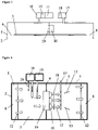
- Figure 1 shows the air conditioning assembly 1 that is used to create the environmental chamber 2.
- the air conditioning assembly 1 is configured to be mounted behind a suspended ceiling 3, that leaves a plenum space 5 between the suspended ceiling 3 and the structural ceiling 4 of the room.
- the plenum space 5 is an air handling space to facilitate air circulation, heating and air conditioning systems within buildings.
- a suspended ceiling 3 is also known as a dropped ceiling or false ceiling.
- the room may comprise an existing room within a building, or may be purpose built for use as an environmental chamber 2, and therefore may comprise a prefabricated shell, not shown.
- the suspended ceiling 3 spans the entire width of the room, leaving no gaps between the edge of the suspended ceiling 3 and the walls 7.
- the suspended ceiling 3 is configured to leave a first perimeter gap 6 and a second perimeter gap 8 between the suspended ceiling 3 and the walls 7 of the environmental chamber 2.
- the suspended ceiling 3 therefore spans the length of the environmental chamber 2, however leaving the first perimeter gap 6 and second perimeter gap 8 at opposing walls 7.
- the suspended ceiling 3 may of course span the full length of the environmental chamber 2, and the first perimeter gap 6 and second perimeter gap 8 may be where the suspended ceiling 3 meets the walls 7 of the environmental chamber 2, across the width of the environmental chamber 2, depending on the orientation of the air conditioning assembly 1 mounted within the plenum space 5.
- the first perimeter gap 6 is configured to provide an effective air outlet from the test space of the environmental chamber 2 into the plenum space 5, this first perimeter gap 6 stretching along substantially the entire edge of the suspended ceiling 3.
- the second perimeter gap 8 is configured to provide an effective air inlet from the plenum space 5 into the test space of the environmental chamber 2, with again this second perimeter gap 8 stretching along substantially the entire opposite edge of the suspended ceiling 3. Air flow 12 can therefore travel between plenum space 5 and test space in a relatively unobstructed manner.
- the vertical wall 9 is configured to support a plurality of fans 10, mounted to it, or placed alongside, with corresponding apertures within the vertical wall 9 to allow air flow 12 to be drawn through the vertical wall 9 and into the plurality of fans 10.
- the plurality of fans 10 provide flow control means for varying the rate of flow of the air flow 12 flowing through the plenum space 5 and therefore the test space below.
- the plurality of fans 10 draw air from the test space up through the first perimeter gap 6 and into the plenum space 5, and blow air through the plenum space 5, down through the second perimeter gap 8 and into the test space below.
- the fans 10 are configured to provide as laminar flow as possible throughout the test space below.
- the fans 10 may be provided with vanes 13, to assist with spreading the air flow 12 across the full expanse of environmental chamber 2.
- the plurality of fans 10 may also be spaced across the full width of the environmental chamber 2 again to create as uniform air flow 12 as possible to be blown into the test space.
- the suspended ceiling 3 conceals the air conditioning assembly 1 in its most basic form, thus leaving the room aesthetically pleasing to the eye and clutter free.
- An air conditioning means 11 is in fluid communication with the plurality of fans 10, such that the air conditioning means 11 can alter the air flow 12 in a required way.
- the air conditioning means 11 is configured according to the requirements of the environmental chamber 2.
- the air conditioning means 11 may be configured to be within the plenum space 5 before the vertical wall 9, or alternatively the air conditioning means 11 may be configured to be after the vertical wall 9, or in a further embodiment, some air conditioning means 11 may be configured before the vertical wall 9 and some may be configured after the vertical wall 9, depending on the requirements of the test space and the function of the component of air conditioning means 11.
- the air conditioning means 11 comprises an altitude simulator 15 and any one or more of the following items: a dehumidifier 16, a humidifier 17, a heater 18, a cooling radiator 19.
- the air conditioning means 11 may comprise any one of this list of items, or more than one of each of the items, or any combination of this list of items, again as singles or multiples depending on the specific requirements of the environmental chamber 2.
- the air conditioning means 11 may be provided as a modular arrangement of component items that are all configured to act upon the same air flow 12.
- the air conditioning means 11, with or without the plurality of fans 10, may be contained within a housing, not shown. Or the items may be mounted individually, or in various arrangements, to a framework of the suspended ceiling 3, not shown.
- the air conditioning means 11, in any required configuration of units is external to the environmental chamber 2, and in fluid communication with the plenum space 5 through ducting.
- the altitude simulator 15 is configured to provide a hypoxic or hyperoxic air flow 12 to the test space.
- the altitude simulator 15 provides a variable injection of oxygen to the air flow 12 for reducing or increasing the simulated altitude experienced by test subjects within the test space.
- the air conditioning means 11 provides environmental control devices to the test space. These environmental control devices simulate altitude, provide relative humidity and variable temperature of air flow 12 through the test space.
- the dehumidifier 16 such as an evaporator unit or chilled water fan coil, is configured to remove humidity from the air flow 12.
- the dehumidifier 16 may form part of a cooling unit, that also provides means to reduce the temperature of the air flow 12.
- the humidifier 17 may comprise a steam injector, or other humidifying device.
- the humidifier 17 is configured to provide humidity to the air flow 12.
- the heater 18 may comprise one or more heating elements, which are configured to increase the temperature of the air flow 12.
- the cooling radiator 19 is configured to reduce the temperature of the air flow 12.
- Figure 3 shows a further arrangement of air conditioning assembly 1 where the air conditioning means 11, or the required units that make up the air conditioning means 11 specific to a required air flow, are configured external to the environmental chamber 2, and in fluid communication with the plenum space 5 of the environmental chamber 2 through ducting or similar means.
- the ducting directs the air flow 12 away from the plenum space 5, through the air conditioning means 11, and back into the plenum space 5 having been conditioned according to requirements.
- Figure 4 shows a plan view of one arrangement of air conditioning assembly 1 showing three fans 10 in fluid communication with the cooling radiator 19, said fans 10 being arranged to ensure an even spread of air flow 12 across the full width of the plenum space 5.
- Air flow 12 is drawn from the test space through the first perimeter gap 6 and into the plenum space 5. This air flow 12 is drawn through ducting 26 to the dehumidifier 16, dehumidified, then returned to the plenum space 5.
- the altitude simulator 15 supplies supplementary oxygen or removes oxygen from the air flow 12 within the plenum space 5.
- the air flow 12 is drawn through the cooling radiator 19 by the fans 10.
- the fans 10 blow the air through the heater 18, configured to heat the air flow 12 if required.
- the air flow 12 is blown through the plenum space 5 and down through the second perimeter gap 8, returning to the test space as a substantially laminar air flow 12 that spreads the full width of the test space.
- An arrangement of vanes 13 may be provided to help to spread the air flow 12 throughout the width of the plenum space 5, and therefore ensuring the air flow 12 is sufficiently spread throughout the full width of the test space.
- This laminar air flow 12 is supplied to the test space at the required temperature, humidity and oxygen level for the test subjects.
- FIG. 5 shows an additional vertical wall 9 within the plenum space 5, to which the plurality of fans 10 are mounted. This arrangement creates a further air space within the plenum space 5 between the cooling radiator 19 and the vertical wall 9 that supports this cooling radiator 19, and the additional vertical wall 9 that supports the bank of fans 10.
- control means 20 All of these air conditioning devices that make up the air conditioning means 11 are controlled by a control means 20.
- the control means 20 provides a way of controlling each of the devices set up within an environmental chamber 2 independently of each other where necessary, to create a required air flow 12 through the test space.
- Figure 6 shows one embodiment of control means 20, that wirelessly, or through hard wiring systems, provides the means of controlling the air conditioning means 11 within the plenum space 5.
- the control means 20 may be mounted to the walls 7 within the test space, may be outside of the environmental chamber, or may be within a portable device, not shown.
- the control means 20 may also comprise a plurality of sensors, and therefore be mounted within a suitable location within the test space to take a valid reading of the air flow 12.
- the sensors may include any one or more of the following: oxygen sensor 21, temperature sensor 22, relative humidity sensor 23, carbon dioxide sensor 24 for sensing and storing or transmitting data for each of these.
- the control means 20 may incorporate a control panel 25 with button control means or touchscreen facility. A person conducting a test within the test space can therefore take a reading for any one of these, and control the air conditioning means 11 within the air conditioning assembly 1 accordingly.
- the passage of the air flow 12 within the plenum space 5, between air conditioning means 11, may be provided with ducting, not shown.
Landscapes
- Engineering & Computer Science (AREA)
- Chemical & Material Sciences (AREA)
- General Engineering & Computer Science (AREA)
- Mechanical Engineering (AREA)
- Combustion & Propulsion (AREA)
- Health & Medical Sciences (AREA)
- Animal Behavior & Ethology (AREA)
- Veterinary Medicine (AREA)
- Public Health (AREA)
- General Health & Medical Sciences (AREA)
- Life Sciences & Earth Sciences (AREA)
- Pulmonology (AREA)
- Air Conditioning Control Device (AREA)
- Ventilation (AREA)
Description
- This invention pertains generally to the field of air conditioning assemblies for environmental chambers, and in particular, to converting a room to form an environmental chamber.
- Environmental chambers typically comprise an enclosed space within which specific environmental conditions can be controlled, varied and monitored. Test subjects are placed within the chamber, and their performance tracked when subjected to a change in conditions. The temperature and humidity of air flow being blown through the environmental chamber may be varied. There may also be a requirement to simulate altitude within the chamber, in order to establish particular climatic conditions and impose these upon the test subjects. There are a number of uses for such chambers, including, but not limited to, medical or scientific research, materials research, the improvement of human or animal performance and assisting rehabilitation during injury recovery.
- A typical example of an altitude simulator is a hypoxic generator. These are used during hypoxic therapy by individuals to obtain the benefits in physical performance and wellbeing through improved oxygen metabolism. A hypoxic generator is a device that is used to deprive the body of an adequate oxygen supply. These generators comprise apparatus to provide reduced oxygen, or hypoxic air, to a user for active or passive simulated altitude training. Hypoxic gas typically contains less than 21% oxygen concentration.
- Incorporating some element of exposure to reduced oxygen atmospheres into a training program can be beneficial in terms of performance and general wellbeing. It has become a widely used element of training for elite athletes and is starting to become used by amateurs. Key uses might include pre-acclimatisation before travelling to high altitude climates, assisting with weight loss and for maintaining fitness levels when suffering from injury.
- Typically, the aim is for the entire volume of the chamber to experience the same climatic conditions at any one time. Conditions such as temperature, humidity, oxygen level and wind chill can be varied and monitored, allowing proper evaluation and comparisons of those subjects contained within the chamber to be made and conclusions reached. Uniformity of these variable conditions throughout the chamber is required for an effective test to be conducted. However, with existing systems that are currently used to form environmental chambers, this uniformity is very difficult to achieve. More often than not, the chamber has zones that are at the required condition, but pockets that are experiencing very different conditions.
- Environmental chambers typically require numerous devices to be able to create the variable conditions. These devices are often required to cool, heat, humidify, dehumidify the air flow, and vary the oxygen concentration of the air flow passing therethrough. They also require numerous sensors to monitor conditions and ensure that predetermined values are met. When mounted in an environmental chamber, all of this equipment can cause clutter within the chamber itself, and is often visually unattractive. It also inevitably creates the localised climatic pockets as previously described.
- An alternative approach has been to house all climate controlling devices outside of the chamber, connecting these with the chamber through ductwork. This approach would often require an Air Handling Unit, or AHU. This air handling unit would typically comprise a cooling coil, dehumidification device, heaters and a humidifier. Air with reduced, or enhanced, oxygen content can also be introduced into the AHU, or through the ductwork, again creating localised conditions that are often different at the entrance points, exit points and other locations within the chamber.
- Both of these arrangements of environmental chamber have a common disadvantage, namely a poor uniformity of conditions throughout the chamber, which makes proper scientific measurements difficult and, if used for performance, delivers different training environments to athletes exercising within the space. Those near air flow outlet points will experience a different wind chill, and therefore different temperatures and humidity, to those positioned near air flow return points, who will in turn get different conditions to those centrally located within the chamber.
- There is a need to improve the uniformity of environmental conditions throughout the environmental chamber, without impacting upon the test subjects making use of the chamber. There is a need to create an effective laminar air flow throughout the chamber, whilst also providing an assembly for converting a room to become an environmental chamber. There is also an advantage to removing any clutter from such an environmental chamber in order to maximise the space and improve aesthetics.
- The prior art shows a number of devices which attempt to address these needs in various ways.
-
WO 2016 098 598 (Fuji Medical Science Company Limited ) discloses an artificial environmental control chamber for sports science use, that is configured to test the influence of a low-temperature and low-humidity environment on a body. An air blowing device blows air into the test chamber and a cylindrical air ventilation duct is disposed within an upper part of the chamber to assist with air circulation. Whilst providing additional means to improve air flow and uniformity of conditions throughout the chamber, there is still likely to be variation across the chamber. The devices also cause clutter within the test space. - Whilst the prior art appears to address the issue of improving air flow in an environmental chamber by improving air circulation within the chamber, this does not create a laminar flow of air across the chamber, and therefore uniform conditions throughout the test space. This prior art does not address the issue with clutter and machinery being housed within the test space.
-
GB1362249 (BASS LTD JOHN inlet compartment 3 contains a fan mounted on the internal wall and delivering air through into anoutlet compartment 5. Other examples of prior art includeDE102015120138 (ESPEC CORP [JP] ),GB664740 (LEONARD JOHN FOWLER, et al GB2378502 (LTG AG [DE] EP0959862 (HYPOXICO INC [US] ). - The present invention aim to provide an air conditioning assembly to provide air conditioning means within a room, thus turning the room into an environmental chamber, and ensuring uniform environmental conditions throughout the environmental chamber. In addition, embodiments of the present invention aim to provide a clutter-free, concealed solution when converting a room into an environmental chamber.
- According to the present invention, there is provided an air conditioning assembly for an environmental chamber, the air conditioning assembly comprising: a suspended ceiling for suspending below a structural ceiling of the environmental chamber to create a plenum space therebetween, said suspended ceiling being configured to cover a substantially horizontal plane of the environmental chamber whilst leaving a first perimeter gap adjacent to a wall of the environmental chamber, and a second perimeter gap adjacent to an opposing wall of the environmental chamber; a substantially vertical wall for covering a vertical plane of the plenum space; at least one fan within the plenum space, said at least one fan being configured to draw air from one side of the substantially vertical wall to the other side, and therefore configured to draw air from the environmental chamber and into the plenum space through the first perimeter gap, and to blow air from the plenum space and into the environmental chamber through the second perimeter gap; and, at least one air conditioning means in fluid communication with the at least one fan, configured to condition the air flow passing through said at least one fan; wherein the at least one air conditioning means comprises an altitude simulator for changing the oxygen content of the air flow, and the first perimeter gap and the second perimeter gap are configured such that they span along substantially the entire edge of the suspended ceiling such that, in use, the air conditioning assembly is configured to create substantially laminar air flow throughout the environmental chamber.
- The air conditioning means may comprise a dehumidifier for reducing the humidity of the air flow.
- The air conditioning means may comprise a humidifier for increasing the humidity of the air flow.
- The air conditioning means may comprise a heater to increase the temperature of the air flow.
- The air conditioning means may comprise a cooling radiator to reduce the temperature of the air flow.
- Preferably, the air conditioning assembly comprises at least one sensor.
- The at least one sensor may be an oxygen sensor.
- The at least one sensor may be a temperature sensor.
- The at least one sensor may be a humidity sensor.
- The at least one sensor may be a carbon dioxide sensor.
- Preferably, the air conditioning assembly may comprise at least one control means operatively connected to the at least one fan and the at least one air conditioning means.
- The air conditioning assembly may comprise at least one control means operatively connected to the at least one sensor.
- The vertical wall may comprise a cooling coil.
- The at least one fan may incorporate a plurality of vanes for directing the air flow to the full width of the environmental chamber.
- The vertical wall may comprise a partitioning board.
- The vertical wall may comprise sealing means for sealing the vertical wall within the plenum space, and at least one aperture corresponding with an inlet of the at least one fan.
- The air conditioning means may be mounted external to the environmental chamber, and in fluid communication with the plenum space through ducting.
- The air conditioning assembly may comprise flow directing means.
- Preferably, the flow directing means may comprise curved ceiling coving.
- Alternatively, the flow directing means comprises planar, inclined coving.
- The invention extends to an environmental chamber incorporating the air conditioning assembly of any of the preceding aspects of the invention.
- The walls and structural ceiling may comprise a prefabricated shell.
- Also according to the present invention, there is provided a method of installing the air conditioning assembly of any of the preceding aspects of the invention in a room to form an environmental chamber, comprising the steps of: installing a suspended ceiling below a structural ceiling of the room to create a plenum space therebetween, said suspended ceiling being configured to cover a substantially horizontal plane of the environmental chamber whilst leaving a first perimeter gap adjacent to a wall of the environmental chamber, and a second perimeter gap adjacent to an opposing wall of the environmental chamber; whereby the first perimeter gap and the second perimeter gap span substantially the entire edge of the suspended ceiling; installing a substantially vertical wall to cover a vertical of the plenum space; installing at least one fan within the substantially vertical wall, said at least one fan being configured to draw air from the environmental chamber and into the plenum space through the first perimeter gap, and to blow air from the plenum space and into the environmental chamber through the second perimeter gap; and, installing at least one air conditioning means in fluid communication with the at least one fan, configured to condition the air flow passing through said at least one fan; wherein the at least one air conditioning means comprises an altitude simulator and, in use, the air conditioning assembly is configured to create substantially laminar air flow throughout the environmental chamber.
- For a better understanding of the invention and to show how embodiments of the same may be carried into effect, reference will now be made, by way of example, to the accompanying diagrammatic drawings, in which:
-
Figure 1 shows one embodiment of air conditioning assembly within a room to create an environmental chamber, showing a plenum space between structural ceiling and suspended ceiling, and laminar air flow created within the chamber by the air conditioning assembly; -
Figure 2 shows the air conditioning assembly ofFigure 1 operatively connected to a plurality of air conditioning means; -
Figure 3 shows a further arrangement of air conditioning means, with a plurality of air conditioning means configured external to the environmental chamber, and in fluid communication with the plenum space through ducting; -
Figure 4 shows the air conditioning assembly ofFigure 1 in plan view, showing one arrangement of plurality of fans; -
Figure 5 shows the air conditioning assembly ofFigure 1 in plan view, showing an alternative arrangement of plurality of fans; and, -
Figure 6 shows one embodiment of control means housing a plurality of sensors. - In the figures like references denote like or corresponding parts.
-
Figure 1 shows theair conditioning assembly 1 that is used to create theenvironmental chamber 2. Theair conditioning assembly 1 is configured to be mounted behind a suspendedceiling 3, that leaves aplenum space 5 between the suspendedceiling 3 and the structural ceiling 4 of the room. Theplenum space 5 is an air handling space to facilitate air circulation, heating and air conditioning systems within buildings. A suspendedceiling 3 is also known as a dropped ceiling or false ceiling. The room may comprise an existing room within a building, or may be purpose built for use as anenvironmental chamber 2, and therefore may comprise a prefabricated shell, not shown. - The suspended
ceiling 3 spans the entire width of the room, leaving no gaps between the edge of the suspendedceiling 3 and thewalls 7. The suspendedceiling 3 is configured to leave afirst perimeter gap 6 and asecond perimeter gap 8 between the suspendedceiling 3 and thewalls 7 of theenvironmental chamber 2. The suspendedceiling 3 therefore spans the length of theenvironmental chamber 2, however leaving thefirst perimeter gap 6 andsecond perimeter gap 8 at opposingwalls 7. The suspendedceiling 3 may of course span the full length of theenvironmental chamber 2, and thefirst perimeter gap 6 andsecond perimeter gap 8 may be where the suspendedceiling 3 meets thewalls 7 of theenvironmental chamber 2, across the width of theenvironmental chamber 2, depending on the orientation of theair conditioning assembly 1 mounted within theplenum space 5. - The
first perimeter gap 6 is configured to provide an effective air outlet from the test space of theenvironmental chamber 2 into theplenum space 5, thisfirst perimeter gap 6 stretching along substantially the entire edge of the suspendedceiling 3. Likewise thesecond perimeter gap 8 is configured to provide an effective air inlet from theplenum space 5 into the test space of theenvironmental chamber 2, with again thissecond perimeter gap 8 stretching along substantially the entire opposite edge of the suspendedceiling 3.Air flow 12 can therefore travel betweenplenum space 5 and test space in a relatively unobstructed manner. - Within the
plenum space 5 and mounted between suspendedceiling 3 and structural ceiling 4 is a substantiallyvertical wall 9, saidvertical wall 9 being sealed by sealingmeans 14 between both suspendedceiling 3 and structural ceiling 4, and adjoiningwalls 7. Thevertical wall 9 is configured to support a plurality offans 10, mounted to it, or placed alongside, with corresponding apertures within thevertical wall 9 to allowair flow 12 to be drawn through thevertical wall 9 and into the plurality offans 10. The plurality offans 10 provide flow control means for varying the rate of flow of theair flow 12 flowing through theplenum space 5 and therefore the test space below. The plurality offans 10 draw air from the test space up through thefirst perimeter gap 6 and into theplenum space 5, and blow air through theplenum space 5, down through thesecond perimeter gap 8 and into the test space below. Thefans 10 are configured to provide as laminar flow as possible throughout the test space below. Thefans 10 may be provided withvanes 13, to assist with spreading theair flow 12 across the full expanse ofenvironmental chamber 2. The plurality offans 10 may also be spaced across the full width of theenvironmental chamber 2 again to create asuniform air flow 12 as possible to be blown into the test space. The suspendedceiling 3 conceals theair conditioning assembly 1 in its most basic form, thus leaving the room aesthetically pleasing to the eye and clutter free. - An air conditioning means 11 is in fluid communication with the plurality of
fans 10, such that the air conditioning means 11 can alter theair flow 12 in a required way. The air conditioning means 11 is configured according to the requirements of theenvironmental chamber 2. The air conditioning means 11 may be configured to be within theplenum space 5 before thevertical wall 9, or alternatively the air conditioning means 11 may be configured to be after thevertical wall 9, or in a further embodiment, some air conditioning means 11 may be configured before thevertical wall 9 and some may be configured after thevertical wall 9, depending on the requirements of the test space and the function of the component of air conditioning means 11. - The air conditioning means 11 comprises an
altitude simulator 15 and any one or more of the following items: adehumidifier 16, ahumidifier 17, aheater 18, a coolingradiator 19. The air conditioning means 11 may comprise any one of this list of items, or more than one of each of the items, or any combination of this list of items, again as singles or multiples depending on the specific requirements of theenvironmental chamber 2. The air conditioning means 11 may be provided as a modular arrangement of component items that are all configured to act upon thesame air flow 12. The air conditioning means 11, with or without the plurality offans 10, may be contained within a housing, not shown. Or the items may be mounted individually, or in various arrangements, to a framework of the suspendedceiling 3, not shown. In yet a further embodiment, the air conditioning means 11, in any required configuration of units, is external to theenvironmental chamber 2, and in fluid communication with theplenum space 5 through ducting. - The
altitude simulator 15 is configured to provide a hypoxic orhyperoxic air flow 12 to the test space. Thealtitude simulator 15 provides a variable injection of oxygen to theair flow 12 for reducing or increasing the simulated altitude experienced by test subjects within the test space. - The air conditioning means 11 provides environmental control devices to the test space. These environmental control devices simulate altitude, provide relative humidity and variable temperature of
air flow 12 through the test space. Thedehumidifier 16, such as an evaporator unit or chilled water fan coil, is configured to remove humidity from theair flow 12. Thedehumidifier 16 may form part of a cooling unit, that also provides means to reduce the temperature of theair flow 12. Thehumidifier 17 may comprise a steam injector, or other humidifying device. Thehumidifier 17 is configured to provide humidity to theair flow 12. Theheater 18 may comprise one or more heating elements, which are configured to increase the temperature of theair flow 12. The coolingradiator 19 is configured to reduce the temperature of theair flow 12. -
Figure 3 shows a further arrangement ofair conditioning assembly 1 where the air conditioning means 11, or the required units that make up the air conditioning means 11 specific to a required air flow, are configured external to theenvironmental chamber 2, and in fluid communication with theplenum space 5 of theenvironmental chamber 2 through ducting or similar means. The ducting directs theair flow 12 away from theplenum space 5, through the air conditioning means 11, and back into theplenum space 5 having been conditioned according to requirements. -
Figure 4 shows a plan view of one arrangement ofair conditioning assembly 1 showing threefans 10 in fluid communication with the coolingradiator 19, saidfans 10 being arranged to ensure an even spread ofair flow 12 across the full width of theplenum space 5.Air flow 12 is drawn from the test space through thefirst perimeter gap 6 and into theplenum space 5. Thisair flow 12 is drawn throughducting 26 to thedehumidifier 16, dehumidified, then returned to theplenum space 5. If required, thealtitude simulator 15 supplies supplementary oxygen or removes oxygen from theair flow 12 within theplenum space 5. Theair flow 12 is drawn through the coolingradiator 19 by thefans 10. Thefans 10 blow the air through theheater 18, configured to heat theair flow 12 if required. Thehumidifier 17, such as a steam injection lance, supplies humidity or moisture to theair flow 12, if required. Theair flow 12 is blown through theplenum space 5 and down through thesecond perimeter gap 8, returning to the test space as a substantiallylaminar air flow 12 that spreads the full width of the test space. An arrangement ofvanes 13 may be provided to help to spread theair flow 12 throughout the width of theplenum space 5, and therefore ensuring theair flow 12 is sufficiently spread throughout the full width of the test space. Thislaminar air flow 12 is supplied to the test space at the required temperature, humidity and oxygen level for the test subjects. - The plan view of
Figure 5 shows an additionalvertical wall 9 within theplenum space 5, to which the plurality offans 10 are mounted. This arrangement creates a further air space within theplenum space 5 between the coolingradiator 19 and thevertical wall 9 that supports this coolingradiator 19, and the additionalvertical wall 9 that supports the bank offans 10. - All of these air conditioning devices that make up the air conditioning means 11 are controlled by a control means 20. The control means 20 provides a way of controlling each of the devices set up within an
environmental chamber 2 independently of each other where necessary, to create a requiredair flow 12 through the test space. -
Figure 6 shows one embodiment of control means 20, that wirelessly, or through hard wiring systems, provides the means of controlling the air conditioning means 11 within theplenum space 5. The control means 20 may be mounted to thewalls 7 within the test space, may be outside of the environmental chamber, or may be within a portable device, not shown. - The control means 20 may also comprise a plurality of sensors, and therefore be mounted within a suitable location within the test space to take a valid reading of the
air flow 12. The sensors may include any one or more of the following:oxygen sensor 21,temperature sensor 22,relative humidity sensor 23,carbon dioxide sensor 24 for sensing and storing or transmitting data for each of these. The control means 20 may incorporate acontrol panel 25 with button control means or touchscreen facility. A person conducting a test within the test space can therefore take a reading for any one of these, and control the air conditioning means 11 within theair conditioning assembly 1 accordingly. - The passage of the
air flow 12 within theplenum space 5, between air conditioning means 11, may be provided with ducting, not shown.
Claims (15)
- An air conditioning assembly (1) for an environmental chamber (2), the air conditioning assembly (1) comprising:- a suspended ceiling (3) for suspending below a structural ceiling (4) of the environmental chamber (2) to create a plenum space (5) therebetween, said suspended ceiling (3) being configured to cover a substantially horizontal plane of the environmental chamber (2) whilst leaving a first perimeter gap (6) adjacent to a wall (7) of the environmental chamber (2), and a second perimeter gap (8) adjacent to an opposing wall (7) of the environmental chamber (2);- a substantially vertical wall (9) for covering a vertical plane of the plenum space (5);- at least one fan (10) within the plenum space (5), said at least one fan (10) being configured to draw air from one side of the substantially vertical wall (9) to the other side, and therefore configured to draw air from the environmental chamber (2) and into the plenum space (5) through the first perimeter gap (6), and to blow air from the plenum space (5) and into the environmental chamber (2) through the second perimeter gap (8); and,- at least one air conditioning means (11) in fluid communication with the at least one fan (10), configured to condition the air flow passing through said at least one fan (10);characterized in that the at least one air conditioning means (11) comprises an altitude simulator (15) for changing the oxygen content of the air flow, and the first perimeter gap (6) and the second perimeter gap (8) are configured such that they span along substantially the entire edge of the suspended ceiling (3) such that, in use, the air conditioning assembly (1) is configured to create substantially laminar air flow throughout the environmental chamber (2).
- An air conditioning assembly (1) according to Claim 1, wherein the air conditioning means (11) comprises a dehumidifier (16) for reducing the humidity of the air flow and/or a humidifier (17) for increasing the humidity of the air flow.
- An air conditioning assembly (1) according to Claim 1 or 2, wherein the air conditioning means (11) comprises a heater (18) to increase the temperature of the air flow and/or a cooling radiator (19) to reduce the temperature of the air flow.
- An air conditioning assembly (1) according to any one of the preceding claims, wherein the air conditioning assembly (1) comprises at least one sensor selected from the group comprising oxygen sensor (21), temperature sensor (22), humidity sensor (23) and carbon dioxide sensor (24).
- An air conditioning assembly (1) according to any one of the preceding claims, wherein the air conditioning assembly (1) comprises at least one control means (20) operatively connected to the at least one fan (10) and the at least one air conditioning means (11).
- An air conditioning assembly (1) according to claims 4 and 5, wherein the air conditioning assembly (1) comprises at least one control means (20) operatively connected to the at least one sensor.
- An air conditioning assembly (1) according to any one of the preceding claims, wherein the vertical wall (9) comprises a cooling coil and/or a partitioning board.
- An air conditioning assembly (1) according to any one of the preceding claims, wherein the at least one fan (10) incorporates a plurality of vanes (13) for directing the air flow to the full width of the environmental chamber (2).
- An air conditioning assembly (1) according to any one of the preceding claims, wherein the vertical wall (9) comprises sealing means (14) for sealing the vertical wall (9) within the plenum space (5), and at least one aperture corresponding with an inlet of the at least one fan (10).
- An air conditioning assembly (1) according to claims 1 to 9, wherein the air conditioning means (11) is mounted external to the environmental chamber (2), and in fluid communication with the plenum space (5) through ducting (26).
- An air conditioning assembly (1) according to any one of the preceding claims, wherein the air conditioning assembly (1) comprises flow directing means.
- An air conditioning assembly (1) according to claim 11, wherein the flow directing means comprises curved ceiling coving or planar, inclined coving.
- An environmental chamber (2) incorporating the air conditioning assembly (1) of any one of the preceding claims.
- An environmental chamber (2) according to claim 13, wherein the walls (7) and structural ceiling (4) comprise a prefabricated shell.
- A method of installing the air conditioning assembly (1) of any of the preceding claims in a room to form an environmental chamber (2), comprising the steps of:- installing a suspended ceiling (3) below a structural ceiling (4) of the room to create a plenum space (5) therebetween, said suspended ceiling (3) being configured to cover a substantially horizontal plane of the environmental chamber (2) whilst leaving a first perimeter gap (6) adjacent to a wall of the environmental chamber (2), and a second perimeter gap (8) adjacent to an opposing wall of the environmental chamber (2) whereby the first perimeter gap (6) and the second perimeter gap (8) span substantially the entire edge of the suspended ceiling (3);- installing a substantially vertical wall (9) to cover a vertical plane of the plenum space (5);- installing at least one fan (10) within the substantially vertical wall (9), said at least one fan (10) being configured to draw air from the environmental chamber (2) and into the plenum space (5) through the first perimeter gap (6), and to blow air from the plenum space (5) and into the environmental chamber (2) through the second perimeter gap (8); and,- installing at least one air conditioning means (11) in fluid communication with the at least one fan (10), configured to condition the air flow passing through said at least one fan (10);wherein the at least one air conditioning means (11) comprises an altitude simulator (15) and, in use, the air conditioning assembly (1) is configured to create substantially laminar air flow throughout the environmental chamber (2).
Applications Claiming Priority (2)
| Application Number | Priority Date | Filing Date | Title |
|---|---|---|---|
| GB201700458A GB2558625B (en) | 2017-01-11 | 2017-01-11 | An air conditioning assembly |
| PCT/GB2018/000005 WO2018130807A1 (en) | 2017-01-11 | 2018-01-11 | An air conditioning assembly |
Publications (2)
| Publication Number | Publication Date |
|---|---|
| EP3568647A1 EP3568647A1 (en) | 2019-11-20 |
| EP3568647B1 true EP3568647B1 (en) | 2022-04-27 |
Family
ID=58463776
Family Applications (1)
| Application Number | Title | Priority Date | Filing Date |
|---|---|---|---|
| EP18700800.8A Active EP3568647B1 (en) | 2017-01-11 | 2018-01-11 | An air conditioning assembly |
Country Status (4)
| Country | Link |
|---|---|
| US (1) | US11951045B2 (en) |
| EP (1) | EP3568647B1 (en) |
| GB (1) | GB2558625B (en) |
| WO (1) | WO2018130807A1 (en) |
Families Citing this family (1)
| Publication number | Priority date | Publication date | Assignee | Title |
|---|---|---|---|---|
| GB2603480B (en) | 2021-02-03 | 2023-08-09 | Sporting Edge Uk Ltd | An air conditioning assembly |
Family Cites Families (12)
| Publication number | Priority date | Publication date | Assignee | Title |
|---|---|---|---|---|
| GB664740A (en) * | 1949-07-27 | 1952-01-09 | Leonard John Fowler | Improvements in or relating to heating or air-conditioning of rooms |
| US3511162A (en) * | 1969-02-20 | 1970-05-12 | Johnson & Johnson | Apparatus and method for isolating a patient zone |
| BE515349A (en) | 1971-06-18 | |||
| CH672833A5 (en) | 1986-09-30 | 1989-12-29 | Barcol Air | |
| US5799652A (en) * | 1995-05-22 | 1998-09-01 | Hypoxico Inc. | Hypoxic room system and equipment for Hypoxic training and therapy at standard atmospheric pressure |
| US6405543B2 (en) * | 1997-05-16 | 2002-06-18 | Work Smart Energy Enterprises Inc. | High-efficiency air-conditioning system with high-volume air distribution |
| WO2002020136A1 (en) * | 2000-09-06 | 2002-03-14 | Colorado Altitude Training Llc | Altitude simulation method and system |
| FR2815112B1 (en) * | 2000-10-09 | 2004-07-16 | Alain Triboix | AIR CONDITIONING DEVICE IMPLEMENTING A FALSE CEILING AND ENSURING AIR DIFFUSION ALONG THE WALLS |
| DE10223085B4 (en) * | 2001-06-06 | 2006-04-13 | Ltg Aktiengesellschaft | Device for heating and / or cooling a room |
| PT1462076E (en) * | 2003-03-28 | 2011-10-24 | Medical Technology Transfer Holding B V | Operation unit |
| JP6296964B2 (en) | 2014-11-27 | 2018-03-20 | エスペック株式会社 | Environmental test equipment and cooling equipment |
| JP6359440B2 (en) * | 2014-12-15 | 2018-07-18 | 富士医科産業株式会社 | Artificial environment control room for sports science |
-
2017
- 2017-01-11 GB GB201700458A patent/GB2558625B/en not_active Expired - Fee Related
-
2018
- 2018-01-11 EP EP18700800.8A patent/EP3568647B1/en active Active
- 2018-01-11 WO PCT/GB2018/000005 patent/WO2018130807A1/en not_active Ceased
- 2018-01-11 US US16/477,079 patent/US11951045B2/en active Active
Also Published As
| Publication number | Publication date |
|---|---|
| GB201700458D0 (en) | 2017-02-22 |
| WO2018130807A1 (en) | 2018-07-19 |
| US20190328595A1 (en) | 2019-10-31 |
| GB2558625B (en) | 2020-01-01 |
| GB2558625A (en) | 2018-07-18 |
| EP3568647A1 (en) | 2019-11-20 |
| US11951045B2 (en) | 2024-04-09 |
Similar Documents
| Publication | Publication Date | Title |
|---|---|---|
| Fong et al. | Evaluation of thermal comfort conditions in a classroom with three ventilation methods | |
| Oh et al. | The effect of airspeed and wind direction on human's thermal conditions and air distribution around the body | |
| US20140326795A1 (en) | Training Room and Use Thereof | |
| Tian et al. | The impact of temperature on mean local air age and thermal comfort in a stratum ventilated office | |
| KR101456869B1 (en) | Induction structure of chilled beam with improved induction performance | |
| Junjing et al. | Performance evaluation of an integrated Personalized Ventilation–Personalized Exhaust system in conjunction with two background ventilation systems | |
| JP2003166729A (en) | Air conditioning systems for communication / information processing equipment rooms, etc. | |
| Cheng et al. | Technical feasibility of a stratum-ventilated room for multiple rows of occupants | |
| Chen et al. | Experimental and simulated energy performance of a personalized ventilation system with individual airflow control in a hot and humid climate | |
| CN107943162A (en) | Modular environment control room | |
| Liu et al. | Demand-oriented differentiated multi-zone thermal environment: Regulating air supply direction and velocity under stratum ventilation | |
| US11951045B2 (en) | Air conditioning assembly | |
| Conceicao et al. | Study of airflow around occupants seated in desks equipped with upper and lower air terminal devices for slightly warm environments | |
| Tham et al. | Performance evaluation of the coupling of a desktop personalized ventilation air terminal device and desk mounted fans | |
| US12070426B2 (en) | Air conditioning assembly | |
| US11173447B2 (en) | Portable dehumidifying chamber | |
| CN213691034U (en) | A variable passageway device for training of fleing | |
| Sheng et al. | Draft-free air conditioning through split membrane ceiling system: An exploratory study | |
| CN105980787A (en) | Artificial environmental control chamber for sports science | |
| Jean et al. | Experimental study on the performance evaluation of active chilled beams in cooling operation under varied boundary conditions | |
| US20140071617A1 (en) | Cooling host module | |
| Naddunuri et al. | Recent developments and findings in the Personalized ventilation system design and performance | |
| Zhao et al. | The characteristics of airborne transmission and thermal comfort with the micro-environment systems and perforated duct system | |
| KR940002643B1 (en) | Interior atmosphere control system | |
| Fang et al. | HVAC systems in a field laboratory for indoor climate study |
Legal Events
| Date | Code | Title | Description |
|---|---|---|---|
| STAA | Information on the status of an ep patent application or granted ep patent |
Free format text: STATUS: UNKNOWN |
|
| STAA | Information on the status of an ep patent application or granted ep patent |
Free format text: STATUS: THE INTERNATIONAL PUBLICATION HAS BEEN MADE |
|
| PUAI | Public reference made under article 153(3) epc to a published international application that has entered the european phase |
Free format text: ORIGINAL CODE: 0009012 |
|
| STAA | Information on the status of an ep patent application or granted ep patent |
Free format text: STATUS: REQUEST FOR EXAMINATION WAS MADE |
|
| 17P | Request for examination filed |
Effective date: 20190812 |
|
| AK | Designated contracting states |
Kind code of ref document: A1 Designated state(s): AL AT BE BG CH CY CZ DE DK EE ES FI FR GB GR HR HU IE IS IT LI LT LU LV MC MK MT NL NO PL PT RO RS SE SI SK SM TR |
|
| AX | Request for extension of the european patent |
Extension state: BA ME |
|
| DAV | Request for validation of the european patent (deleted) | ||
| DAX | Request for extension of the european patent (deleted) | ||
| STAA | Information on the status of an ep patent application or granted ep patent |
Free format text: STATUS: EXAMINATION IS IN PROGRESS |
|
| 17Q | First examination report despatched |
Effective date: 20210111 |
|
| GRAP | Despatch of communication of intention to grant a patent |
Free format text: ORIGINAL CODE: EPIDOSNIGR1 |
|
| STAA | Information on the status of an ep patent application or granted ep patent |
Free format text: STATUS: GRANT OF PATENT IS INTENDED |
|
| RIC1 | Information provided on ipc code assigned before grant |
Ipc: F24F 7/06 20060101ALI20211026BHEP Ipc: F24F 1/0047 20190101ALI20211026BHEP Ipc: F24F 110/70 20180101ALI20211026BHEP Ipc: F24F 110/76 20180101ALI20211026BHEP Ipc: F24F 3/14 20060101ALI20211026BHEP Ipc: F24F 13/072 20060101AFI20211026BHEP |
|
| INTG | Intention to grant announced |
Effective date: 20211111 |
|
| GRAS | Grant fee paid |
Free format text: ORIGINAL CODE: EPIDOSNIGR3 |
|
| GRAA | (expected) grant |
Free format text: ORIGINAL CODE: 0009210 |
|
| STAA | Information on the status of an ep patent application or granted ep patent |
Free format text: STATUS: THE PATENT HAS BEEN GRANTED |
|
| AK | Designated contracting states |
Kind code of ref document: B1 Designated state(s): AL AT BE BG CH CY CZ DE DK EE ES FI FR GB GR HR HU IE IS IT LI LT LU LV MC MK MT NL NO PL PT RO RS SE SI SK SM TR |
|
| REG | Reference to a national code |
Ref country code: GB Ref legal event code: FG4D |
|
| REG | Reference to a national code |
Ref country code: CH Ref legal event code: EP |
|
| REG | Reference to a national code |
Ref country code: AT Ref legal event code: REF Ref document number: 1487200 Country of ref document: AT Kind code of ref document: T Effective date: 20220515 |
|
| REG | Reference to a national code |
Ref country code: DE Ref legal event code: R096 Ref document number: 602018034477 Country of ref document: DE |
|
| REG | Reference to a national code |
Ref country code: IE Ref legal event code: FG4D |
|
| REG | Reference to a national code |
Ref country code: NO Ref legal event code: T2 Effective date: 20220427 |
|
| REG | Reference to a national code |
Ref country code: SE Ref legal event code: TRGR |
|
| REG | Reference to a national code |
Ref country code: LT Ref legal event code: MG9D |
|
| REG | Reference to a national code |
Ref country code: NL Ref legal event code: MP Effective date: 20220427 |
|
| REG | Reference to a national code |
Ref country code: AT Ref legal event code: MK05 Ref document number: 1487200 Country of ref document: AT Kind code of ref document: T Effective date: 20220427 |
|
| PG25 | Lapsed in a contracting state [announced via postgrant information from national office to epo] |
Ref country code: NL Free format text: LAPSE BECAUSE OF FAILURE TO SUBMIT A TRANSLATION OF THE DESCRIPTION OR TO PAY THE FEE WITHIN THE PRESCRIBED TIME-LIMIT Effective date: 20220427 |
|
| PG25 | Lapsed in a contracting state [announced via postgrant information from national office to epo] |
Ref country code: PT Free format text: LAPSE BECAUSE OF FAILURE TO SUBMIT A TRANSLATION OF THE DESCRIPTION OR TO PAY THE FEE WITHIN THE PRESCRIBED TIME-LIMIT Effective date: 20220829 Ref country code: LT Free format text: LAPSE BECAUSE OF FAILURE TO SUBMIT A TRANSLATION OF THE DESCRIPTION OR TO PAY THE FEE WITHIN THE PRESCRIBED TIME-LIMIT Effective date: 20220427 Ref country code: HR Free format text: LAPSE BECAUSE OF FAILURE TO SUBMIT A TRANSLATION OF THE DESCRIPTION OR TO PAY THE FEE WITHIN THE PRESCRIBED TIME-LIMIT Effective date: 20220427 Ref country code: GR Free format text: LAPSE BECAUSE OF FAILURE TO SUBMIT A TRANSLATION OF THE DESCRIPTION OR TO PAY THE FEE WITHIN THE PRESCRIBED TIME-LIMIT Effective date: 20220728 Ref country code: FI Free format text: LAPSE BECAUSE OF FAILURE TO SUBMIT A TRANSLATION OF THE DESCRIPTION OR TO PAY THE FEE WITHIN THE PRESCRIBED TIME-LIMIT Effective date: 20220427 Ref country code: ES Free format text: LAPSE BECAUSE OF FAILURE TO SUBMIT A TRANSLATION OF THE DESCRIPTION OR TO PAY THE FEE WITHIN THE PRESCRIBED TIME-LIMIT Effective date: 20220427 Ref country code: BG Free format text: LAPSE BECAUSE OF FAILURE TO SUBMIT A TRANSLATION OF THE DESCRIPTION OR TO PAY THE FEE WITHIN THE PRESCRIBED TIME-LIMIT Effective date: 20220727 Ref country code: AT Free format text: LAPSE BECAUSE OF FAILURE TO SUBMIT A TRANSLATION OF THE DESCRIPTION OR TO PAY THE FEE WITHIN THE PRESCRIBED TIME-LIMIT Effective date: 20220427 |
|
| PG25 | Lapsed in a contracting state [announced via postgrant information from national office to epo] |
Ref country code: RS Free format text: LAPSE BECAUSE OF FAILURE TO SUBMIT A TRANSLATION OF THE DESCRIPTION OR TO PAY THE FEE WITHIN THE PRESCRIBED TIME-LIMIT Effective date: 20220427 Ref country code: PL Free format text: LAPSE BECAUSE OF FAILURE TO SUBMIT A TRANSLATION OF THE DESCRIPTION OR TO PAY THE FEE WITHIN THE PRESCRIBED TIME-LIMIT Effective date: 20220427 Ref country code: LV Free format text: LAPSE BECAUSE OF FAILURE TO SUBMIT A TRANSLATION OF THE DESCRIPTION OR TO PAY THE FEE WITHIN THE PRESCRIBED TIME-LIMIT Effective date: 20220427 Ref country code: IS Free format text: LAPSE BECAUSE OF FAILURE TO SUBMIT A TRANSLATION OF THE DESCRIPTION OR TO PAY THE FEE WITHIN THE PRESCRIBED TIME-LIMIT Effective date: 20220827 |
|
| REG | Reference to a national code |
Ref country code: DE Ref legal event code: R097 Ref document number: 602018034477 Country of ref document: DE |
|
| PG25 | Lapsed in a contracting state [announced via postgrant information from national office to epo] |
Ref country code: SM Free format text: LAPSE BECAUSE OF FAILURE TO SUBMIT A TRANSLATION OF THE DESCRIPTION OR TO PAY THE FEE WITHIN THE PRESCRIBED TIME-LIMIT Effective date: 20220427 Ref country code: SK Free format text: LAPSE BECAUSE OF FAILURE TO SUBMIT A TRANSLATION OF THE DESCRIPTION OR TO PAY THE FEE WITHIN THE PRESCRIBED TIME-LIMIT Effective date: 20220427 Ref country code: RO Free format text: LAPSE BECAUSE OF FAILURE TO SUBMIT A TRANSLATION OF THE DESCRIPTION OR TO PAY THE FEE WITHIN THE PRESCRIBED TIME-LIMIT Effective date: 20220427 Ref country code: EE Free format text: LAPSE BECAUSE OF FAILURE TO SUBMIT A TRANSLATION OF THE DESCRIPTION OR TO PAY THE FEE WITHIN THE PRESCRIBED TIME-LIMIT Effective date: 20220427 Ref country code: DK Free format text: LAPSE BECAUSE OF FAILURE TO SUBMIT A TRANSLATION OF THE DESCRIPTION OR TO PAY THE FEE WITHIN THE PRESCRIBED TIME-LIMIT Effective date: 20220427 Ref country code: CZ Free format text: LAPSE BECAUSE OF FAILURE TO SUBMIT A TRANSLATION OF THE DESCRIPTION OR TO PAY THE FEE WITHIN THE PRESCRIBED TIME-LIMIT Effective date: 20220427 |
|
| PLBE | No opposition filed within time limit |
Free format text: ORIGINAL CODE: 0009261 |
|
| STAA | Information on the status of an ep patent application or granted ep patent |
Free format text: STATUS: NO OPPOSITION FILED WITHIN TIME LIMIT |
|
| PG25 | Lapsed in a contracting state [announced via postgrant information from national office to epo] |
Ref country code: AL Free format text: LAPSE BECAUSE OF FAILURE TO SUBMIT A TRANSLATION OF THE DESCRIPTION OR TO PAY THE FEE WITHIN THE PRESCRIBED TIME-LIMIT Effective date: 20220427 |
|
| 26N | No opposition filed |
Effective date: 20230130 |
|
| PG25 | Lapsed in a contracting state [announced via postgrant information from national office to epo] |
Ref country code: SI Free format text: LAPSE BECAUSE OF FAILURE TO SUBMIT A TRANSLATION OF THE DESCRIPTION OR TO PAY THE FEE WITHIN THE PRESCRIBED TIME-LIMIT Effective date: 20220427 |
|
| REG | Reference to a national code |
Ref country code: CH Ref legal event code: PL |
|
| REG | Reference to a national code |
Ref country code: BE Ref legal event code: MM Effective date: 20230131 |
|
| PG25 | Lapsed in a contracting state [announced via postgrant information from national office to epo] |
Ref country code: LI Free format text: LAPSE BECAUSE OF NON-PAYMENT OF DUE FEES Effective date: 20230131 Ref country code: CH Free format text: LAPSE BECAUSE OF NON-PAYMENT OF DUE FEES Effective date: 20230131 |
|
| PG25 | Lapsed in a contracting state [announced via postgrant information from national office to epo] |
Ref country code: BE Free format text: LAPSE BECAUSE OF NON-PAYMENT OF DUE FEES Effective date: 20230131 |
|
| PG25 | Lapsed in a contracting state [announced via postgrant information from national office to epo] |
Ref country code: IT Free format text: LAPSE BECAUSE OF FAILURE TO SUBMIT A TRANSLATION OF THE DESCRIPTION OR TO PAY THE FEE WITHIN THE PRESCRIBED TIME-LIMIT Effective date: 20220427 Ref country code: IE Free format text: LAPSE BECAUSE OF NON-PAYMENT OF DUE FEES Effective date: 20230111 |
|
| PG25 | Lapsed in a contracting state [announced via postgrant information from national office to epo] |
Ref country code: MC Free format text: LAPSE BECAUSE OF FAILURE TO SUBMIT A TRANSLATION OF THE DESCRIPTION OR TO PAY THE FEE WITHIN THE PRESCRIBED TIME-LIMIT Effective date: 20220427 |
|
| PG25 | Lapsed in a contracting state [announced via postgrant information from national office to epo] |
Ref country code: MC Free format text: LAPSE BECAUSE OF FAILURE TO SUBMIT A TRANSLATION OF THE DESCRIPTION OR TO PAY THE FEE WITHIN THE PRESCRIBED TIME-LIMIT Effective date: 20220427 |
|
| PG25 | Lapsed in a contracting state [announced via postgrant information from national office to epo] |
Ref country code: BG Free format text: LAPSE BECAUSE OF FAILURE TO SUBMIT A TRANSLATION OF THE DESCRIPTION OR TO PAY THE FEE WITHIN THE PRESCRIBED TIME-LIMIT Effective date: 20220427 |
|
| PG25 | Lapsed in a contracting state [announced via postgrant information from national office to epo] |
Ref country code: BG Free format text: LAPSE BECAUSE OF FAILURE TO SUBMIT A TRANSLATION OF THE DESCRIPTION OR TO PAY THE FEE WITHIN THE PRESCRIBED TIME-LIMIT Effective date: 20220427 |
|
| PG25 | Lapsed in a contracting state [announced via postgrant information from national office to epo] |
Ref country code: CY Free format text: LAPSE BECAUSE OF FAILURE TO SUBMIT A TRANSLATION OF THE DESCRIPTION OR TO PAY THE FEE WITHIN THE PRESCRIBED TIME-LIMIT; INVALID AB INITIO Effective date: 20180111 |
|
| PG25 | Lapsed in a contracting state [announced via postgrant information from national office to epo] |
Ref country code: HU Free format text: LAPSE BECAUSE OF FAILURE TO SUBMIT A TRANSLATION OF THE DESCRIPTION OR TO PAY THE FEE WITHIN THE PRESCRIBED TIME-LIMIT; INVALID AB INITIO Effective date: 20180111 |
|
| PG25 | Lapsed in a contracting state [announced via postgrant information from national office to epo] |
Ref country code: TR Free format text: LAPSE BECAUSE OF FAILURE TO SUBMIT A TRANSLATION OF THE DESCRIPTION OR TO PAY THE FEE WITHIN THE PRESCRIBED TIME-LIMIT Effective date: 20220427 |
|
| PGFP | Annual fee paid to national office [announced via postgrant information from national office to epo] |
Ref country code: GB Payment date: 20251222 Year of fee payment: 9 |
|
| PGFP | Annual fee paid to national office [announced via postgrant information from national office to epo] |
Ref country code: LU Payment date: 20260122 Year of fee payment: 9 |
|
| PGFP | Annual fee paid to national office [announced via postgrant information from national office to epo] |
Ref country code: SE Payment date: 20260126 Year of fee payment: 9 |
|
| PGFP | Annual fee paid to national office [announced via postgrant information from national office to epo] |
Ref country code: NO Payment date: 20260120 Year of fee payment: 9 Ref country code: DE Payment date: 20260127 Year of fee payment: 9 |
|
| PGFP | Annual fee paid to national office [announced via postgrant information from national office to epo] |
Ref country code: FR Payment date: 20260126 Year of fee payment: 9 |