EP3568290B1 - Assemblage comprenant un tissu partiellement rompable et une structure porteuse - Google Patents
Assemblage comprenant un tissu partiellement rompable et une structure porteuse Download PDFInfo
- Publication number
- EP3568290B1 EP3568290B1 EP18702755.2A EP18702755A EP3568290B1 EP 3568290 B1 EP3568290 B1 EP 3568290B1 EP 18702755 A EP18702755 A EP 18702755A EP 3568290 B1 EP3568290 B1 EP 3568290B1
- Authority
- EP
- European Patent Office
- Prior art keywords
- transverse straight
- fabric
- straight zone
- filamentary
- group
- Prior art date
- Legal status (The legal status is an assumption and is not a legal conclusion. Google has not performed a legal analysis and makes no representation as to the accuracy of the status listed.)
- Active
Links
- 239000004744 fabric Substances 0.000 title claims description 377
- 230000008093 supporting effect Effects 0.000 title description 48
- 238000004873 anchoring Methods 0.000 claims description 71
- 239000000203 mixture Substances 0.000 claims description 62
- 238000004519 manufacturing process Methods 0.000 claims description 26
- 230000036961 partial effect Effects 0.000 claims description 17
- 238000000034 method Methods 0.000 claims description 13
- 238000000926 separation method Methods 0.000 claims description 8
- 230000001747 exhibiting effect Effects 0.000 claims description 7
- 229920000642 polymer Polymers 0.000 claims description 5
- 150000001875 compounds Chemical class 0.000 claims 1
- 210000001519 tissue Anatomy 0.000 description 79
- 230000035882 stress Effects 0.000 description 46
- 229920001971 elastomer Polymers 0.000 description 25
- 239000000806 elastomer Substances 0.000 description 24
- 229920000728 polyester Polymers 0.000 description 23
- 238000004804 winding Methods 0.000 description 22
- 239000000463 material Substances 0.000 description 19
- 239000000835 fiber Substances 0.000 description 17
- 229920002725 thermoplastic elastomer Polymers 0.000 description 17
- 239000010410 layer Substances 0.000 description 16
- 239000004952 Polyamide Substances 0.000 description 15
- 229920002647 polyamide Polymers 0.000 description 15
- 229920001470 polyketone Polymers 0.000 description 13
- 239000008186 active pharmaceutical agent Substances 0.000 description 11
- 230000002787 reinforcement Effects 0.000 description 10
- 229920001577 copolymer Polymers 0.000 description 9
- -1 isocyanate compound Chemical class 0.000 description 9
- 239000004753 textile Substances 0.000 description 9
- 210000000056 organ Anatomy 0.000 description 8
- 239000005020 polyethylene terephthalate Substances 0.000 description 8
- 229920000139 polyethylene terephthalate Polymers 0.000 description 8
- 229920002635 polyurethane Polymers 0.000 description 8
- 239000004814 polyurethane Substances 0.000 description 8
- 229920001169 thermoplastic Polymers 0.000 description 8
- 230000003044 adaptive effect Effects 0.000 description 7
- 150000001993 dienes Chemical class 0.000 description 7
- 230000008569 process Effects 0.000 description 7
- 230000003014 reinforcing effect Effects 0.000 description 7
- 238000007493 shaping process Methods 0.000 description 7
- 229920003244 diene elastomer Polymers 0.000 description 6
- 244000043261 Hevea brasiliensis Species 0.000 description 5
- 239000000853 adhesive Substances 0.000 description 5
- 230000001070 adhesive effect Effects 0.000 description 5
- 230000008901 benefit Effects 0.000 description 5
- 230000006835 compression Effects 0.000 description 5
- 238000007906 compression Methods 0.000 description 5
- 238000009940 knitting Methods 0.000 description 5
- 239000002557 mineral fiber Substances 0.000 description 5
- 229920003052 natural elastomer Polymers 0.000 description 5
- 229920001194 natural rubber Polymers 0.000 description 5
- 238000005096 rolling process Methods 0.000 description 5
- APHFXDBDLKPMTA-UHFFFAOYSA-N Art1 Natural products CCCCCCCCCC(=O)c1c(CC(O)=O)cc2cc(O)cc(O)c2c1O APHFXDBDLKPMTA-UHFFFAOYSA-N 0.000 description 4
- 101100047770 Mus musculus Tspan32 gene Proteins 0.000 description 4
- 230000006399 behavior Effects 0.000 description 4
- 235000009508 confectionery Nutrition 0.000 description 4
- 238000009826 distribution Methods 0.000 description 4
- RRHGJUQNOFWUDK-UHFFFAOYSA-N Isoprene Chemical compound CC(=C)C=C RRHGJUQNOFWUDK-UHFFFAOYSA-N 0.000 description 3
- 229920000297 Rayon Polymers 0.000 description 3
- 239000004760 aramid Substances 0.000 description 3
- 229920003235 aromatic polyamide Polymers 0.000 description 3
- 230000015572 biosynthetic process Effects 0.000 description 3
- 230000006355 external stress Effects 0.000 description 3
- 238000000265 homogenisation Methods 0.000 description 3
- 238000005470 impregnation Methods 0.000 description 3
- 230000001976 improved effect Effects 0.000 description 3
- 229920003207 poly(ethylene-2,6-naphthalate) Polymers 0.000 description 3
- 239000011112 polyethylene naphthalate Substances 0.000 description 3
- 238000002360 preparation method Methods 0.000 description 3
- 239000002964 rayon Substances 0.000 description 3
- 239000004416 thermosoftening plastic Substances 0.000 description 3
- 238000004073 vulcanization Methods 0.000 description 3
- 239000004953 Aliphatic polyamide Substances 0.000 description 2
- 239000004677 Nylon Substances 0.000 description 2
- 239000005062 Polybutadiene Substances 0.000 description 2
- PPBRXRYQALVLMV-UHFFFAOYSA-N Styrene Chemical compound C=CC1=CC=CC=C1 PPBRXRYQALVLMV-UHFFFAOYSA-N 0.000 description 2
- 230000009471 action Effects 0.000 description 2
- 229920003231 aliphatic polyamide Polymers 0.000 description 2
- 230000000712 assembly Effects 0.000 description 2
- 238000000429 assembly Methods 0.000 description 2
- 239000011324 bead Substances 0.000 description 2
- 229920001400 block copolymer Polymers 0.000 description 2
- MTAZNLWOLGHBHU-UHFFFAOYSA-N butadiene-styrene rubber Chemical compound C=CC=C.C=CC1=CC=CC=C1 MTAZNLWOLGHBHU-UHFFFAOYSA-N 0.000 description 2
- 239000011203 carbon fibre reinforced carbon Substances 0.000 description 2
- 230000008602 contraction Effects 0.000 description 2
- 238000005520 cutting process Methods 0.000 description 2
- 239000013536 elastomeric material Substances 0.000 description 2
- 239000003292 glue Substances 0.000 description 2
- 230000010354 integration Effects 0.000 description 2
- 239000000178 monomer Substances 0.000 description 2
- 229920001778 nylon Polymers 0.000 description 2
- 229920002857 polybutadiene Polymers 0.000 description 2
- 229920001707 polybutylene terephthalate Polymers 0.000 description 2
- 239000005060 rubber Substances 0.000 description 2
- 229920006395 saturated elastomer Polymers 0.000 description 2
- 229920003051 synthetic elastomer Polymers 0.000 description 2
- 238000009864 tensile test Methods 0.000 description 2
- ROGIWVXWXZRRMZ-UHFFFAOYSA-N 2-methylbuta-1,3-diene;styrene Chemical compound CC(=C)C=C.C=CC1=CC=CC=C1 ROGIWVXWXZRRMZ-UHFFFAOYSA-N 0.000 description 1
- VSKJLJHPAFKHBX-UHFFFAOYSA-N 2-methylbuta-1,3-diene;styrene Chemical compound CC(=C)C=C.C=CC1=CC=CC=C1.C=CC1=CC=CC=C1 VSKJLJHPAFKHBX-UHFFFAOYSA-N 0.000 description 1
- VGGSQFUCUMXWEO-UHFFFAOYSA-N Ethene Chemical compound C=C VGGSQFUCUMXWEO-UHFFFAOYSA-N 0.000 description 1
- 239000005977 Ethylene Substances 0.000 description 1
- 239000004743 Polypropylene Substances 0.000 description 1
- 239000004793 Polystyrene Substances 0.000 description 1
- 239000004372 Polyvinyl alcohol Substances 0.000 description 1
- 241001080024 Telles Species 0.000 description 1
- 239000000654 additive Substances 0.000 description 1
- 238000004026 adhesive bonding Methods 0.000 description 1
- VLLYOYVKQDKAHN-UHFFFAOYSA-N buta-1,3-diene;2-methylbuta-1,3-diene Chemical compound C=CC=C.CC(=C)C=C VLLYOYVKQDKAHN-UHFFFAOYSA-N 0.000 description 1
- 239000006229 carbon black Substances 0.000 description 1
- 239000000969 carrier Substances 0.000 description 1
- 229920002678 cellulose Polymers 0.000 description 1
- 239000001913 cellulose Substances 0.000 description 1
- 230000001143 conditioned effect Effects 0.000 description 1
- 239000000470 constituent Substances 0.000 description 1
- 238000010276 construction Methods 0.000 description 1
- 238000004132 cross linking Methods 0.000 description 1
- 230000000694 effects Effects 0.000 description 1
- 239000003822 epoxy resin Substances 0.000 description 1
- 230000002349 favourable effect Effects 0.000 description 1
- 239000000446 fuel Substances 0.000 description 1
- 230000009477 glass transition Effects 0.000 description 1
- 229920001519 homopolymer Polymers 0.000 description 1
- 239000012943 hotmelt Substances 0.000 description 1
- 238000009434 installation Methods 0.000 description 1
- 239000012948 isocyanate Substances 0.000 description 1
- 229920000126 latex Polymers 0.000 description 1
- 239000004816 latex Substances 0.000 description 1
- 230000000670 limiting effect Effects 0.000 description 1
- 239000002184 metal Substances 0.000 description 1
- 238000005457 optimization Methods 0.000 description 1
- 230000008520 organization Effects 0.000 description 1
- 230000035515 penetration Effects 0.000 description 1
- 229920000647 polyepoxide Polymers 0.000 description 1
- 229920001195 polyisoprene Polymers 0.000 description 1
- 229920002223 polystyrene Polymers 0.000 description 1
- 229920002451 polyvinyl alcohol Polymers 0.000 description 1
- 230000001737 promoting effect Effects 0.000 description 1
- 230000009467 reduction Effects 0.000 description 1
- 230000002829 reductive effect Effects 0.000 description 1
- 239000012763 reinforcing filler Substances 0.000 description 1
- 230000000284 resting effect Effects 0.000 description 1
- 230000000717 retained effect Effects 0.000 description 1
- 230000002441 reversible effect Effects 0.000 description 1
- 238000007789 sealing Methods 0.000 description 1
- 239000002356 single layer Substances 0.000 description 1
- 239000007787 solid Substances 0.000 description 1
- 229920006132 styrene block copolymer Polymers 0.000 description 1
- 125000003011 styrenyl group Chemical group [H]\C(*)=C(/[H])C1=C([H])C([H])=C([H])C([H])=C1[H] 0.000 description 1
- 125000000383 tetramethylene group Chemical group [H]C([H])([*:1])C([H])([H])C([H])([H])C([H])([H])[*:2] 0.000 description 1
- KAKZBPTYRLMSJV-UHFFFAOYSA-N vinyl-ethylene Natural products C=CC=C KAKZBPTYRLMSJV-UHFFFAOYSA-N 0.000 description 1
Images


Classifications
-
- B—PERFORMING OPERATIONS; TRANSPORTING
- B29—WORKING OF PLASTICS; WORKING OF SUBSTANCES IN A PLASTIC STATE IN GENERAL
- B29D—PRODUCING PARTICULAR ARTICLES FROM PLASTICS OR FROM SUBSTANCES IN A PLASTIC STATE
- B29D30/00—Producing pneumatic or solid tyres or parts thereof
- B29D30/02—Solid tyres ; Moulds therefor
-
- B—PERFORMING OPERATIONS; TRANSPORTING
- B60—VEHICLES IN GENERAL
- B60C—VEHICLE TYRES; TYRE INFLATION; TYRE CHANGING; CONNECTING VALVES TO INFLATABLE ELASTIC BODIES IN GENERAL; DEVICES OR ARRANGEMENTS RELATED TO TYRES
- B60C9/00—Reinforcements or ply arrangement of pneumatic tyres
- B60C9/18—Structure or arrangement of belts or breakers, crown-reinforcing or cushioning layers
- B60C9/1807—Structure or arrangement of belts or breakers, crown-reinforcing or cushioning layers comprising fabric reinforcements
-
- B—PERFORMING OPERATIONS; TRANSPORTING
- B29—WORKING OF PLASTICS; WORKING OF SUBSTANCES IN A PLASTIC STATE IN GENERAL
- B29C—SHAPING OR JOINING OF PLASTICS; SHAPING OF MATERIAL IN A PLASTIC STATE, NOT OTHERWISE PROVIDED FOR; AFTER-TREATMENT OF THE SHAPED PRODUCTS, e.g. REPAIRING
- B29C70/00—Shaping composites, i.e. plastics material comprising reinforcements, fillers or preformed parts, e.g. inserts
- B29C70/04—Shaping composites, i.e. plastics material comprising reinforcements, fillers or preformed parts, e.g. inserts comprising reinforcements only, e.g. self-reinforcing plastics
- B29C70/06—Fibrous reinforcements only
- B29C70/10—Fibrous reinforcements only characterised by the structure of fibrous reinforcements, e.g. hollow fibres
- B29C70/16—Fibrous reinforcements only characterised by the structure of fibrous reinforcements, e.g. hollow fibres using fibres of substantial or continuous length
- B29C70/22—Fibrous reinforcements only characterised by the structure of fibrous reinforcements, e.g. hollow fibres using fibres of substantial or continuous length oriented in at least two directions forming a two dimensional structure
- B29C70/228—Fibrous reinforcements only characterised by the structure of fibrous reinforcements, e.g. hollow fibres using fibres of substantial or continuous length oriented in at least two directions forming a two dimensional structure the structure being stacked in parallel layers with fibres of adjacent layers crossing at substantial angles
-
- B—PERFORMING OPERATIONS; TRANSPORTING
- B29—WORKING OF PLASTICS; WORKING OF SUBSTANCES IN A PLASTIC STATE IN GENERAL
- B29C—SHAPING OR JOINING OF PLASTICS; SHAPING OF MATERIAL IN A PLASTIC STATE, NOT OTHERWISE PROVIDED FOR; AFTER-TREATMENT OF THE SHAPED PRODUCTS, e.g. REPAIRING
- B29C70/00—Shaping composites, i.e. plastics material comprising reinforcements, fillers or preformed parts, e.g. inserts
- B29C70/04—Shaping composites, i.e. plastics material comprising reinforcements, fillers or preformed parts, e.g. inserts comprising reinforcements only, e.g. self-reinforcing plastics
- B29C70/06—Fibrous reinforcements only
- B29C70/10—Fibrous reinforcements only characterised by the structure of fibrous reinforcements, e.g. hollow fibres
- B29C70/16—Fibrous reinforcements only characterised by the structure of fibrous reinforcements, e.g. hollow fibres using fibres of substantial or continuous length
- B29C70/24—Fibrous reinforcements only characterised by the structure of fibrous reinforcements, e.g. hollow fibres using fibres of substantial or continuous length oriented in at least three directions forming a three dimensional structure
-
- B—PERFORMING OPERATIONS; TRANSPORTING
- B60—VEHICLES IN GENERAL
- B60C—VEHICLE TYRES; TYRE INFLATION; TYRE CHANGING; CONNECTING VALVES TO INFLATABLE ELASTIC BODIES IN GENERAL; DEVICES OR ARRANGEMENTS RELATED TO TYRES
- B60C17/00—Tyres characterised by means enabling restricted operation in damaged or deflated condition; Accessories therefor
- B60C17/04—Tyres characterised by means enabling restricted operation in damaged or deflated condition; Accessories therefor utilising additional non-inflatable supports which become load-supporting in emergency
-
- B—PERFORMING OPERATIONS; TRANSPORTING
- B60—VEHICLES IN GENERAL
- B60C—VEHICLE TYRES; TYRE INFLATION; TYRE CHANGING; CONNECTING VALVES TO INFLATABLE ELASTIC BODIES IN GENERAL; DEVICES OR ARRANGEMENTS RELATED TO TYRES
- B60C3/00—Tyres characterised by the transverse section
- B60C3/02—Closed, e.g. toroidal, tyres
-
- B—PERFORMING OPERATIONS; TRANSPORTING
- B60—VEHICLES IN GENERAL
- B60C—VEHICLE TYRES; TYRE INFLATION; TYRE CHANGING; CONNECTING VALVES TO INFLATABLE ELASTIC BODIES IN GENERAL; DEVICES OR ARRANGEMENTS RELATED TO TYRES
- B60C9/00—Reinforcements or ply arrangement of pneumatic tyres
- B60C9/02—Carcasses
-
- B—PERFORMING OPERATIONS; TRANSPORTING
- B29—WORKING OF PLASTICS; WORKING OF SUBSTANCES IN A PLASTIC STATE IN GENERAL
- B29D—PRODUCING PARTICULAR ARTICLES FROM PLASTICS OR FROM SUBSTANCES IN A PLASTIC STATE
- B29D30/00—Producing pneumatic or solid tyres or parts thereof
- B29D30/06—Pneumatic tyres or parts thereof (e.g. produced by casting, moulding, compression moulding, injection moulding, centrifugal casting)
- B29D30/0681—Parts of pneumatic tyres; accessories, auxiliary operations
- B29D2030/0683—Additional internal supports to be positioned inside the tyre, as emergency supports for run-flat tyres
-
- B—PERFORMING OPERATIONS; TRANSPORTING
- B60—VEHICLES IN GENERAL
- B60C—VEHICLE TYRES; TYRE INFLATION; TYRE CHANGING; CONNECTING VALVES TO INFLATABLE ELASTIC BODIES IN GENERAL; DEVICES OR ARRANGEMENTS RELATED TO TYRES
- B60C17/00—Tyres characterised by means enabling restricted operation in damaged or deflated condition; Accessories therefor
Definitions
- the subject of the invention is an assembly, an impregnated assembly, a tire, a mounted assembly and a method of manufacturing a tire.
- the invention relates to the field of tires intended to be fitted to vehicles.
- the tire is preferably designed for passenger vehicles, but can be used on any other type of vehicle such as two-wheeled vehicles, heavy goods vehicles, agricultural vehicles, civil engineering vehicles or airplanes or, more generally, on any device. rolling.
- a conventional tire is a toric structure, intended to be mounted on a rim, pressurized by an inflation gas and crushed on the ground under the action of a load.
- the tire has a double curvature at every point of its tread surface, intended to come into contact with the ground: a circumferential curvature and a meridian curvature.
- circumferential curvature is meant a curvature in a circumferential plane, defined by a circumferential direction, tangent to the tread surface of the tire in the direction of travel of the tire, and a radial direction, perpendicular to the axis of rotation of the tire.
- meridian curvature is meant a curvature in a meridian or radial plane, defined by an axial direction, parallel to the axis of rotation of the tire, and a radial direction, perpendicular to the axis of rotation of the tire.
- the expression “radially inner, respectively radially outer” means “closer, respectively further away from the axis of rotation of the tire”.
- the expression “axially inner, respectively axially outer” means “closer to, respectively further away from the equatorial plane of the tire", the equatorial plane of the tire being the plane passing through the middle of the tread surface of the tire and perpendicular to the tire. axis of rotation of the tire.
- the flattening of the tire on a horizontal ground, in a circumferential plane and in a meridian plane is conditioned by the values of the respectively circumferential and meridian radii of curvature, at the points of the rolling surface positioned at the corners. limits of the contact area of the tire with the ground.
- This flattening is all the more facilitated as these radii of curvature are large, that is to say that the curvatures are small, the curvature at a point, in the mathematical sense, being the inverse of the radius of curvature.
- the flattening of the tire has an impact on the performance of the tire, in particular the rolling resistance, the grip, the wear and the noise.
- a conventional tire of the state of the art generally has a large meridian curvature, that is to say a small meridian radius of curvature, at the level of the axial ends of the tread, called shoulders, when the tire is mounted. on its mounting rim and inflated to its recommended working pressure, is subject to its service load.
- the mounting rim, the working pressure and the working load are defined by standards, such as, for example, the standards of the European Tire and Rim Technical Organization (ETRTO).
- a conventional tire carries the applied load, essentially by the axial ends of the tread, or shoulders, and by the sidewalls connecting the tread to beads providing the mechanical connection of the tire with its mounting rim. It is known that a meridian flattening of a conventional tire, with a small meridian curvature at the level of the shoulders, is generally difficult to obtain.
- the document US 4235270 describes a tire having an annular body made of elastomeric material, comprising a radially outer cylindrical part, at the periphery of the tire, which may include a tread, and a radially inner cylindrical part, intended to be mounted on a rim.
- a plurality of walls, spaced in the circumferential direction, extend from the radially inner cylindrical part to the radially outer cylindrical part, and ensure the carrying of the load.
- sidewalls can connect the two cylindrical parts, respectively radially inner and radially outer, to form, in association with the tread and the sidewalls, a closed cavity and thus allow the pressurization of the tire.
- such a tire has a high mass, compared to a conventional tire, and, because of its massive nature, is capable of dissipating high energy, which can limit its endurance, and therefore its life.
- the document WO 2009087291 describes a pneumatic structure comprising two annular rings, respectively internal, or radially internal, and external, or radially external, connected by two sidewalls and by a supporting structure.
- the supporting structure is pressurized and divides the annular volume of the tire into a plurality of compartments or cells, and the sidewalls are linked or integrated into the supporting structure.
- the applied load is increased to both by the supporting structure and the sides.
- the pressure distribution in the contact area is not homogeneous across the axial width of the contact area, with overpressures at the shoulders due to the difficulty of flattening the meridian due to the connection between the sides and the supporting structure. These overpressures at the shoulders are liable to generate significant wear on the shoulders of the tread.
- the document WO 2005007422 discloses an adaptive wheel comprising an adaptive band and a plurality of spokes extending radially inward from the adaptive band to a hub.
- the adaptive band is intended to adapt to the contact surface with a ground and to wrap around obstacles.
- the spokes transmit the load carried between the adaptive band and the hub, thanks to the tensioning of the spokes which are not in contact with the ground.
- Such an adaptive wheel requires optimization of the distribution of the spokes in order to guarantee a substantially cylindrical periphery.
- an adaptive wheel has a relatively high mass compared to a conventional tire.
- the document WO 2016/116491 A1 describes a tire comprising a first and a second structure of revolution comprising fabrics or knits comprising wire elements, concentric and connected by a supporting structure comprising alternatively wire elements.
- the object of the present invention is to provide a tire which allows improved flattening of the tread when the tire is subjected to a load and which is easy to manufacture from a suitable assembly.
- the principle of the assembly according to the invention is to have a load-bearing structure comprising load-bearing elements connecting the first fabric and the second fabric or knit, and capable, once the assembly is arranged in the tire, of carrying the applied load. to the tire by tensioning part of the supporting elements positioned outside the contact area, the supporting elements positioned in the contact area being subjected to buckling because they are subjected to a compressive force and therefore do not participate not when carrying the applied load.
- the assembly according to the invention can be unbleached, that is to say devoid of any adhesive composition intended to promote adhesion between the first wire elements of the first fabric and / or the second wire elements of the second fabric or knit with an elastomer composition.
- the assembly according to the invention can also be bonded, that is to say coated at least in part with at least one adhesive composition promoting such adhesion.
- each first and second wire member to be bonded is coated with a layer of an adhesion primer and the adhesion primer layer is coated with a layer of adhesive composition.
- each first and second wire member to be bonded is directly coated with a layer of adhesive composition.
- an adhesion primer is an epoxy resin and / or an isocyanate compound, optionally blocked.
- the adhesive composition used can be a conventional RFL glue (Resorcinol-formaldehyde-latex) or even the glues described in the applications.
- RFL glue Resorcinol-formaldehyde-latex
- general direction is meant the general direction in which the fabric or knit extends along its greatest length and which is parallel to the longitudinal edges of the fabric or knit.
- a fabric or a knit wound on a spool of revolution about an axis has a general direction substantially parallel to the direction of unwinding of the fabric or knit (ie the circumferential direction) which is perpendicular to the axial and radial directions. of the coil.
- the first chain direction being substantially parallel to the first general direction and the first fabric being sufficiently deformable, the tire manufacturing process is greatly facilitated. Indeed, the first tissue can be deformed by the elongation of the first cord organ without completely breaking of so as to extend sufficiently to follow the conformation imposed on it during the manufacture of the tire.
- the breaking of the second wire member makes it possible to have a first fabric having a relatively high rigidity and a relatively low capacity to elongate during the manufacturing process of the first fabric, making the latter easier to use compared to a first fabric. in which the first wire chain elements would be more elastic and would have a relatively high capacity to elongate. The use of such first wire chain elements makes it possible to obtain relatively large elongations.
- This deformability of the first fabric makes it possible to lay the first fabric by simply winding it around the preparation cylinder, unlike other embodiments in which other solutions, much more industrially complex, must be used to allow the first fabric to follow the conformation imposed during the manufacture of the tire. Finally, despite the breakage of the second wire member, the woven structure of the first fabric is retained due to the non-rupture of the first wire member which allows a continuous chain structure to be maintained in the first tissue.
- the first fabric forms a first structure of first wire elements.
- the second fabric or knit forms a second structure of second wire elements.
- the properties of the first fabric are determined by subjecting the first fabric to a tensile test in accordance with standard NF EN ISO 13934-1 of July 2013.
- the intrinsic properties of the elements and wire members are determined by subjecting the elements wire to a tensile test in accordance with ASTM D885 / D885 MA of January 2010.
- H represents, once the assembly has been integrated into the tire, the average radial height of the internal annular space radially delimited by the internal face of the first fabric and the internal face of the second fabric or knit in the absence of load applied to the tire and in the absence of pressure in the tire.
- This radial height is at least equal to 0.5 times the average straight distance between the two faces for a supporting wire portion at rest so that, once the assembly is arranged in the tire, the assembly is capable of carrying the load.
- applied to the tire by the tensioning of a part of the supporting elements positioned outside the contact area, the supporting elements positioned in the contact area being subjected to buckling because they are subjected to a compressive force and do not participate therefore not when carrying the applied load.
- H H0 x K and Art> (2 ⁇ x H0 x K) / L with Art being the elongation at maximum force measured in accordance with standard NF EN ISO 13934-1 of July 2013.
- H0 x K ⁇ H ⁇ H0 is such that, in the absence of load applied to the tire and in the absence of pressure in the tire, each carrying wire portion is in a folded state.
- wire carrier element any elongate element of great length relative to its cross section, whatever the shape of the latter, for example circular, oblong, rectangular or square, or even flat, this wire element possibly being twisted, for example. or wavy.
- its diameter is preferably less than 5 mm, more preferably within a range ranging from 100 ⁇ m to 1.2 mm.
- average straight distance between the internal face of the first fabric and the internal face of the second fabric or knit is understood to mean the distance measured perpendicularly to these two faces. In other words, it is the shortest distance between these two faces. This straight distance is measured and averaged over at least 5 different points equally distributed over the assembly at rest.
- resting length of the first fabric is meant a length of the first fabric which is neither in extension nor in compression in the first general direction and therefore has zero elongation in this first general direction.
- the first fabric is then not subjected to any external stress other than its own weight.
- Each carrier wire element in particular each carrier wire portion which connects the internal faces of the first fabric and of the second fabric or knit to each other, can be characterized geometrically by its length at rest L P and by its mean section S P , which is the average of the sections obtained by cutting the carrier wire portion by all the surfaces parallel to the first fabric and to the second fabric or knit and included between the first fabric and the second fabric or knit.
- the mean section S P is equal to this constant section.
- Each carrier wire element in particular each carrier portion, typically has a smaller characteristic dimension E of its mean section S P (which is the average of the sections obtained by cutting the carrier wire element by all the surfaces parallel to the first fabric and second fabric or knit and between the first fabric and the second fabric or knit, preferably at most equal to 0.02 times the maximum spacing between the two internal faces of the first fabric and of the second fabric or knit (which corresponds to the radial height mean H of the internal annular space once the assembly has been arranged within the tire in the absence of load applied to the tire and in the absence of pressure in the tire) and an aspect ratio R of its mean section S P preferably at most equal to 3.
- E of its mean section S P which is the average of the sections obtained by cutting the carrier wire element by all the surfaces parallel to the first fabric and second fabric or knit and between the first fabric and the second fabric or knit, preferably at most equal to 0.02 times the maximum spacing between the two internal faces of the first fabric and of the second fabric or knit (which corresponds to the radial height mean H of the internal annular space once
- a smallest characteristic dimension E of the average section S P of the supporting element at most equal to 0.02 times the average radial height H of the internal annular space excludes any solid supporting element having a large volume.
- each load-bearing element when it is wired, each load-bearing element has a high slenderness, in the radial direction, allowing it to buckle when passing through the contact area. Outside the contact area, each load-bearing element returns to its initial geometry, because its buckling is reversible. Such a load-bearing element has good resistance to fatigue.
- An aspect ratio R of its mean section S P at most equal to 3 means that the greatest characteristic dimension V of its mean section S P is at most equal to 3 times the smallest characteristic dimension E of its mean section S P.
- a wire carrier element has a mechanical behavior of the wire type, that is to say it can only be subjected to extension or compression forces along its mean line.
- wire carrier elements of a carrier structure do not necessarily have identical lengths at rest L P.
- the supporting structure comprises a plurality of identical supporting elements, that is to say whose geometrical characteristics and the constituent materials are identical.
- the supporting elements are arranged so that they are two by two not mechanically linked in a space delimited by the first fabric and the second fabric or knit.
- the load-bearing elements have independent mechanical behaviors.
- the supporting elements are not linked together so as to form a network or a trellis.
- K 0.90 which allows optimized carrying of the load.
- the second wire member is substantially rectilinear and the first wire member is helically wound around the second wire member.
- Such first wire elements of chains are called wrapped wire elements, the second wire member forming a core around which is wound a wrapper or a layer formed by the first wire member.
- each first and second filamentary member comprises, independently of one another, at least one multifilament strand comprising several monofilaments each consisting of a material chosen from a polyester, a polyamide, a polyketone, a polyurethane, a natural fiber. , a mineral fiber, preferably chosen from a polyester, a polyamide, a polyketone, a polyurethane, a natural fiber and an assembly of these materials, more preferably chosen from a polyester, a natural fiber and an assembly of these materials.
- the first filamentary member comprises at least one multifilament strand comprising several monofilaments each consisting of a material chosen from a polyester, a polyamide, a polyketone, a polyurethane, a natural fiber, preferably chosen from a polyester, a polyamide, a polyketone, a polyurethane and an assembly of these materials, more preferably chosen from polyesters and assemblies of polyesters.
- Polyesters are advantageous by virtue of their high toughness, their low cost, their thermal resistance countable with use in tires and a standard thermal contraction which can be chosen.
- the second filamentary member comprises at least one multifilament strand comprising several monofilaments each consisting of a material chosen from a polyester, a polyamide, a polyketone, a natural fiber, a mineral fiber, preferably chosen from a polyester, a polyamide, a polyketone and a natural fiber and an assembly of these materials, more preferably of rayon.
- Corded rayon members advantageously have relatively low elongation at break.
- the first fabric is deformable under a relatively low stress which makes it possible, during the tire manufacturing process, to use a suitable conformational stress that does not risk damaging the blank.
- the maximum force is the force necessarily to obtain the elongation at the maximum force as defined in the standard NF EN ISO 13934-1 of July 2013. Thus, with imposed stress, one avoids breaking the first tissue during shaping.
- the smaller P0 the more it is possible to use small stresses during the tire manufacturing process and the less risk of damaging the blank during this process.
- each carrier wire element is textile.
- textile is meant that each carrier wire element is non-metallic, and is for example made of a material chosen from a polyester, a polyamide, a polyketone, a polyvinyl alcohol, a cellulose, a mineral fiber, a natural fiber, a material. elastomeric or a mixture of these materials.
- polyesters mention will be made, for example, of PET (polyethylene terephthalate), PEN (polyethylene naphthalate), PBT (polybutylene terephthalate), PBN (polybutylene naphthalate), PPT (polypropylene terephthalate), PPN (polypropylene naphthalate).
- polyamides mention will be made of aliphatic polyamides such as polyamides 4-6, 6, 6-6 (nylon), 11 or 12 and aromatic polyamides such as aramid.
- each carrier wire element is a textile assembly comprising one or more monofilament or multifilament textile fibers, whether or not twisted together.
- each carrier wire element consists of a monofilament.
- Each monofilament or multifilament fiber has a diameter of between 5 and 20 ⁇ m, for example 10 ⁇ m.
- each wire carrier element is metallic, for example an assembly of metallic monofilaments, each metallic monofilament having a diameter typically less than 50 ⁇ m, for example 10 ⁇ m.
- each carrier wire element consists of an assembly of several metal monofilaments.
- each wire carrier element consists of a metallic monofilament.
- each carrier wire element alternately extends from the first fabric to the second fabric or knit and from the second fabric or knit to the first fabric as one moves along the carrier wire member.
- the first fabric comprises first wire elements, called weft, substantially parallel to each other and extending in a first direction, called weft, and intersecting with the first wire warp elements.
- the first fabric comprises, in a manner known to those skilled in the art, a weave characterizing the interweaving of the first wire elements of warp and weft. According to the embodiments, this weave is of the plain, serge or satin type.
- the weave is of the cloth type.
- the first warp and weft directions form with each other an angle ranging from 70 ° to 90 °, preferably substantially equal to 90 °.
- the mechanical characteristics of such fabrics such as their stiffness in extension and their force at maximum tensile force, depending on the direction of the yarn elements of warp or weft, depend on the characteristics of the yarn elements, such as, for textile yarn elements, the titre, expressed in tex or g / 1000 m, the tenacity, expressed in cN / tex, and the standard contraction, expressed in%, these wire elements being distributed according to a given density, expressed in number of threads / dm. All these characteristics depend on the material of which the wire elements are made and on their manufacturing process.
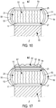
- each wire carrier element comprises a first wire portion for anchoring each wire carrier element in the first fabric extending the wire carrier portion in the first fabric.
- each first wire anchoring portion is interlaced with the first fabric.
- Such an assembly has the advantage of being able to be manufactured in a single step.
- the interlacing of each load-bearing element with the first fabric makes it possible to ensure the mechanical anchoring of each load-bearing element in the first fabric and thus to confer the desired mechanical properties on the supporting structure.
- each first wire anchoring portion is wound at least in part around at least a first wire element of the first fabric.
- each first wire anchoring portion extends in a direction substantially parallel to the first general direction.
- each first wire anchoring portion passes alternately from one face of the first fabric to the other face of the first fabric between two first adjacent weft wire elements around which the first wire anchoring portion is wound.
- the first wire chain elements extend continuously over the entire length of the first fabric.
- the wire chain elements have no discontinuity along their length, with the exception of possible connections between two ends of two wire elements which form a continuous chain wire element.
- each transverse straight zone of the second group of transverse straight zone (s) is arranged so as to prevent an elongation of each zone transverse line of the second group of zone (s) transverse straight line (s) in the first general direction.
- each transverse straight zone of the second group of transverse straight zone (s) is arranged so as to prevent an elongation of each first chain wire element in the first general direction in each transverse straight zone of the second group of transverse straight zone (s).
- each transverse straight zone of the second group of transverse straight zone (s) ( s) is arranged so as to allow an elongation of each transverse straight zone of the second group of transverse straight zone (s) in the first general direction, preferably so as to allow an elongation of each transverse straight zone of the second group of transverse straight zone (s) in the first general direction at most equal to 20%, preferably 15%, and more preferably 10% of the elongation of each transverse straight zone of the first group of transverse straight zone (s) according to the first general direction.
- each transverse straight zone of the second group of transverse straight zone (s) is arranged so as to allow an elongation of each first wire chain element in the first general direction in each transverse straight zone of the second group of transverse straight zone (s), preferably so as to allow an elongation of each first wire chain element in the first general direction in each transverse straight zone of the second group of transverse straight zone (s) at most equal to 20%, preferably to 15%, and more preferably to 10 % of the elongation of each first wire chain element in the first general direction in each transverse straight zone of the first group of transverse straight zone (s).
- a transverse straight zone is delimited longitudinally by two imaginary straight lines substantially perpendicular to the first general direction of the fabric.
- a transverse straight zone extends over the entire width of the fabric, that is to say the transverse straight zone is delimited transversely by the longitudinal edges of the fabric.
- partial rupture is meant a rupture of at least one wire member of each wire chain element of the zone. It is also understood that this is a rupture which is only partial and therefore not total, that is to say not a rupture of all the components constituting each wire chain element of the zone.
- a partial rupture of one zone is a rupture of the second wire member without breaking the first wire member of each wire chain element of the zone.
- a partial rupture of a zone should not be confused with a rupture of certain wire elements of the zone and a non-rupture of other cord elements of the zone, which would not make it possible to conform the first fabric correctly.
- a partial rupture is therefore different from a rupture which must be understood as a total rupture, that is to say a total interruption of each wire element or wire portion concerned unlike a partial rupture in which it is there is no total interruption of each wire element or wire portion concerned.
- each transverse straight zone of the first group of transverse straight zone (s) is arranged so as to allow an elongation with partial breakage of each first chain wire element in the first general direction in at least one transverse straight zone of the first group of transverse straight zone (s), preferably an elongation with partial breakage of each first chain wire element in the first general direction in each transverse straight zone of the first group of transverse straight zone (s).
- each transverse straight zone of the first group of transverse straight zone (s) is arranged so as to allow an elongation without breaking of the first wire member of each first wire chain element according to the first general direction in each transverse straight zone of the first group of transverse straight zone (s) and cause at least one rupture of the second wire member of each first chain wire element in at least one transverse straight zone of the first group of transverse straight zone (s), preferably in each transverse straight zone of the first group of transverse straight zone (s).
- the first fabric comprising first wire elements, called weft elements, substantially parallel to each other and intersecting with the first wire chain elements, each transverse straight zone of the first group of transverse straight zone (s) ) is arranged so as to allow a separation of the weft wire elements relative to each other in the first general direction in each transverse straight zone of the first group of transverse straight zone (s).
- each transverse straight zone of the second group of transverse straight zone (s) is arranged so as to prevent rupture of each first chain wire element in each transverse straight zone of the second group of transverse straight zone (s).
- each transverse straight zone of the second group of transverse straight zone (s) is arranged so as to prevent a separation of the first weft wire elements relative to each other in the first general direction in each transverse straight zone of the second group of transverse straight zone (s).
- each transverse straight zone of the second group of transverse straight zone (s) is arranged so as to allow a separation of the first weft wire elements relative to each other in the first general direction in each transverse straight zone of the second group of transverse straight zone (s).
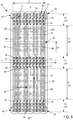
- each transverse straight zone of the first group is a so-called deformable zone.
- Such zones are deformable under the shaping conditions and participate in the conformability of the first fabric.
- each transverse straight zone of the second group is an unbreakable zone.
- Such zones are non-rupturable under the shaping conditions and have little or no part in the conformability of the first fabric. So, each so-called deformable transverse straight zone of the first group is deformed sufficiently to allow the conformation of the assembly and compensates for the non-elongation or the low elongation of the so-called unbreakable transverse straight zones of the second group.
- the elongation at maximum force of all the transverse straight zones of the first group will be all the greater as the so-called deformable transverse straight zones of the first group are short and few in number compared to the unbreakable transverse straight zones of the second group.
- the portions of each first wire chain element located in each so-called deformable transverse straight zone of the first group are deformed sufficiently to allow the assembly to be shaped and compensate for the non-elongation or the low elongation. portions of each first wire chain element located in the so-called unbreakable transverse straight zones of the second group.
- each so-called deformable zone of the first group is deformable under a relatively low stress which allows, during the tire manufacturing process, to use a suitable conformation stress that does not risk damaging the blank, unlike each so-called zone. indeformable and unbreakable of the second group.
- the elongation at maximum force Art1 of each transverse straight zone of the first group of zones transverse line (s) according to the first general direction verifies Art1> (2 ⁇ x H) / SLd1 with SLd1 being the sum of the lengths at rest Ld1 of all the transverse straight zones of the first group of zone (s) transverse line (s).
- the elongation at maximum force is measured in accordance with standard NF EN ISO 13934-1 of July 2013 on samples of transverse straight zones of the first group of transverse straight zone (s).
- the elongation at break Arc of each first wire chain element satisfies Arc> (2 ⁇ x H) / SLd1.
- the elongation at break Arc is measured according to the ASTM D885 / D885 MA standard of January 2010.
- the elongation at break Arc of each first wire chain member is the elongation necessary to obtain the rupture of the first and second wire members.
- the elongation, the stress exerted and the force developed are determined in accordance with standard NF EN ISO 13934-1 of July 2013.
- each transverse straight zone of the second group of transverse straight zone (s) is arranged so as to prevent rupture of each first wire anchoring portion.
- each straight zone comprising at least a first unbreakable anchoring wire portion, even under a relatively high stress which allows, during the tire manufacturing process, to use a suitable conformation stress that does not run the risk of deteriorate the blank.
- each transverse straight zone of the second group of transverse straight zone (s) is arranged so as to prevent an elongation of each first wire anchoring portion in the first general direction.
- each transverse straight zone of the second group of transverse straight zone (s) is arranged so as to allow an extension of each first wire anchoring portion in the first general direction.
- the smaller P0 the more it is possible to use small stresses during the tire manufacturing process and the less risk of damaging the blank during this process.
- each transverse straight zone of the first group of transverse straight zone (s) alternates, in the first general direction, with a transverse straight zone of the second group of transverse straight zone (s) (s).
- a homogeneous deformation of the whole of the first fabric is obtained, this deformation being all the more homogeneous as the length at rest of each transverse straight zone in the first general direction is small.
- length at rest of a transverse straight zone along the first general direction is meant the length of the zone in the longitudinal direction in the absence of any external stress exerted on the zone (other than atmospheric pressure).
- a transverse straight zone at rest in the first general direction is neither in extension nor in compression in this direction and therefore has zero elongation in this direction.
- the second fabric or knit extending in a second general direction, the second general direction is substantially parallel to the first main direction.
- the second fabric comprises, in a manner known to those skilled in the art, a weave characterizing the interweaving of the second wire elements of warp and weft.
- this weave is of the plain, serge or satin type.
- the weave is of the cloth type.
- the second warp and weft directions form with each other an angle ranging from 70 ° to 90 °, preferably substantially equal to 90 °.
- the second fabric extending in a second general direction, the second chain direction of the second wire elements being substantially parallel to the second general direction.
- Such a second fabric allows a process for manufacturing the assembly and the tire that is greatly facilitated.
- the second fabric or knit is a knit comprising intertwined loops.
- each wire carrier element comprises a second wire portion for anchoring each wire carrier element in the second fabric or knit extending the wire carrier portion in the second fabric or knit.
- each second wire anchoring portion is interlaced with the second fabric or knit.
- Such an assembly has the advantage of being able to be manufactured in a single step.
- the interlacing of each carrier element with the second fabric or knit makes it possible to ensure the mechanical anchoring of each carrier element in the second fabric or knit and thus to confer the desired mechanical properties on the carrier structure.
- each second wire anchoring portion is wound at least in part around at least one second wire element of the second fabric or knit.
- each second wire anchoring portion extends in a direction substantially parallel to the second general direction.
- each second threaded anchoring portion passes alternately from one face of the second fabric to the other face of the second fabric between two adjacent second threaded weft elements around which the second threaded anchoring portion is wound.
- the second wire chain elements extend continuously over the entire length of the second fabric.
- Impregnated assembly according to the invention.
- each first fabric and second fabric or knit in the assembly is impregnated with the corresponding polymeric composition.
- each first and second structure of wire elements comprises first and second fabrics impregnated with the corresponding polymeric composition.
- the first structure of first yarn elements comprises a first fabric impregnated with the first polymeric composition and the second structure of second yarn elements comprises a second knit impregnated with the second composition.
- impregnated is understood to mean that each polymeric composition penetrates at least at the surface of the structure of wire elements. It is therefore possible to have a unifacial impregnation with a covering of one face of the structure of wire elements by the polymeric composition or a bifacial impregnation with a coverage of both sides of the structure of wire elements by the polymeric composition. In both cases, the impregnation makes it possible to create a mechanical anchoring thanks to the penetration of the polymeric composition into the interstices present in the structure of wire elements.
- each polymeric composition comprises at least one elastomer, preferably a diene elastomer.
- elastomer or rubber the two terms being synonymous
- diene type is meant in general an elastomer derived at least in part (ie a homopolymer or a copolymer) from diene monomers (monomers bearing two conjugated carbon-carbon double bonds. or not). This composition can then be either in the raw state or in the cooked state.
- the diene elastomer of the rubber composition is chosen from the group consisting of polybutadienes (BR), synthetic polyisoprenes (IR), natural rubber (NR), butadiene copolymers, copolymers of isoprene and mixtures of these elastomers.
- Such copolymers are more preferably chosen from the group consisting of butadiene-styrene (SBR) copolymers, isoprene-butadiene (BIR) copolymers, isoprene-styrene (SIR) copolymers, isoprene-copolymers. butadiene-styrene (SBIR) and mixtures of such copolymers.
- Each polymeric composition may contain a single diene elastomer or a mixture of several diene elastomers, the diene elastomer (s) being able to be used in combination with any type of synthetic elastomer other than diene, or even with polymers other than elastomers, for example elastomers. thermoplastic polymers.
- each polymeric composition comprises, in addition to the elastomer, preferably diene, a reinforcing filler, for example carbon black, a crosslinking system, for example a vulcanization system and additives. various.
- a reinforcing filler for example carbon black
- a crosslinking system for example a vulcanization system and additives.
- each polymeric composition comprises at least one thermoplastic polymer.
- a thermoplastic polymer is by definition hot melt. Examples of such thermoplastic polymers are aliphatic polyamides, for example nylon, polyesters, for example PET or PEN, and thermoplastic elastomers.
- Thermoplastic elastomers are elastomers in the form of block copolymers based on thermoplastic blocks. With an intermediate structure between thermoplastic polymers and elastomers, they consist in a known manner of rigid thermoplastic blocks, in particular polystyrene linked by flexible elastomer blocks, for example polybutadiene or polyisoprene for unsaturated TPEs or poly (ethylene / butylene) for saturated TPEs. This is the reason why, in a known manner, the above TPE block copolymers are generally characterized by the presence of two glass transition peaks, the first peak (lowest temperature, generally negative) being relative to the elastomer block.
- the second peak (highest temperature, positive, typically greater than 80 ° C. for preferential elastomers of the TPS type) relating to the thermoplastic part (for example styrene blocks) of the TPE copolymer.
- These TPE elastomers are often triblock elastomers with two rigid segments connected by a flexible segment. The rigid and flexible segments can be arranged linearly, star or branched. These TPE elastomers can also be diblock elastomers with a single rigid segment connected to a flexible segment.
- each of these segments or blocks contains at least more than 5, generally more than 10 base units (for example styrene units and isoprene units for a styrene / isoprene / styrene block copolymer).
- the thermoplastic elastomer is unsaturated.
- unsaturated TPE elastomer is understood by definition and in a well-known manner to mean a TPE elastomer which is provided with ethylenic unsaturations, that is to say which comprises carbon-carbon double bonds (conjugated or not); conversely, a so-called saturated TPE elastomer is of course a TPE elastomer which lacks such double bonds.
- the first and second polymeric compositions can be different or identical.
- the first polymeric composition can comprise a diene elastomer and the second polymeric composition can comprise a thermoplastic elastomer or vice versa.
- wire carrier portion at rest is understood to mean a wire carrier portion which is neither in extension nor in compression and therefore exhibits zero elongation.
- the carrying wire portion is then subjected to no external stress other than its own weight and the weight of the elements to which it is linked.
- average radial height of the inner annular space is meant the average of the corresponding radial height measured at at least 5 different points circumferentially equi-distributed around the tire and measured in the median circumferential plane of the tire defined as the plane which is normal to the axis of rotation of the tire and which is located equidistant from the reinforcement structures of each bead.
- the first structure of radially outer revolution of the tire is intended to ensure, among other functions, the connection of the assembly with a structure of crown revolution.
- the second radially revolution structure The interior of the tire is intended to ensure, among other functions, the connection of the assembly, and therefore of the tire, with the mounting means.
- the first radially outer structure of revolution of the tire has an axis of revolution coincident with the axis of rotation of the tire.
- the second radially inner revolution structure of the tire is coaxial with the first radially outer revolution structure of the tire.
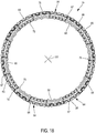
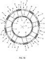
- the inner annular space In the absence of load applied to the tire and in the absence of pressure in the tire, the inner annular space has an average radial height H.
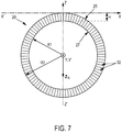
- the load-bearing elements connected to the portion of the first radially outer revolution structure of the tire in contact with the ground via the first fabric, are subjected to compressive buckling and at least some of the load-bearing elements, connected to the portion of the first radially outer revolution structure of the tire not in contact with the ground, are in tension.
- the mean surface density DS of load-bearing wire portions per unit area of the first radially external structure of revolution being at least equal to (S / S E ) * Z N / (A * Fr), where S is the area, in m2, of the radially inner face of a crown structure of revolution, S E is the connecting surface between the outer face of the first radially outer structure of revolution and the radially inner face of the crown structure, in m2, Z N is the nominal radial load, in N, applied to the tire, A is the ground contact area, in m2, of the tire, and Fr is the breaking force , in N, of each load-bearing portion.
- the nominal radial load Z N is the recommended load for the use of the tire.
- the ground contact surface A is the surface according to which the tire is crushed on the ground under the action of the nominal radial load Z N.
- the expression according to which DS is at least equal to (S / S E ) * Z N / (A * Fr) reflects, in particular, the fact that the average surface density DS of the carrier portions is all the greater as the nominal radial load Z N high and / or that the ratio of surfaces S E / S, representing the rate of coverage of the radially inner face of the crown structure of revolution by the first structure of radially outer revolution, is low.
- the average surface density DS of the load-bearing portions is all the lower as the tensile breaking force Fr of a load-bearing portion is high.
- Such an average surface density DS of the load-bearing portions allows, on the one hand, the load-bearing elements extending outside the contact area of carry the nominal radial load Z N , and, on the other hand, to the load-bearing elements in compression in the contact area to guarantee a flattening of the tread, both in a circumferential plane and in a meridian plane , improved compared to tires known from the state of the art.
- the surface density of the load-bearing portions is constant both in the circumferential direction and in the axial direction, that is to say that the distribution of the load-bearing portions is uniform both circumferentially and axially: the average surface density DS is therefore equal to the constant surface density.
- the advantage of a constant surface density is that it contributes to giving the tread a quasi-cylindrical geometry, with a lessened so-called “daisy-chaining” effect compared with other tires of the state of the art.
- the surface density of the bearing portions may be variable in the circumferential direction and / or in the axial direction, that is to say that the distribution of the bearing portions is not necessarily uniform circumferentially and / or axially, hence the introduction of the characteristic of average surface density DS of load-bearing portions.
- the surface density DS of the carrier portions is advantageously at least equal to 3 * (S / S E ) * Z N / (A * Fr).
- a higher surface density of the load-bearing portions improves the homogenization of the pressures in the contact area with the ground and guarantees a higher safety coefficient with respect to the applied load and with respect to endurance.
- the surface density DS of the carrier portions is even more advantageously at least equal to 6 * (S / S E ) * Z N / (A * Fr).
- An even higher surface density of the load-bearing portions further improves the homogenization of the pressures in the ground contact area and makes it possible to further increase the safety coefficient with respect to the applied load and with respect to endurance.
- the average surface density DS of the carrier portions is advantageously at least equal to 5000.
- the surface S E is substantially equal to the surface S, that is to say that the first structure of radially outer revolution completely covers the radially inner face of the top structure of revolution.
- the mean surface density DS of the minimum carrier portions is equal to Z N / (A * Fr).
- S E is different from S and even S E ⁇ S.
- the first structure of revolution is not necessarily continuous (axially and / or circumferentially) and may consist of portions of the structure of juxtaposed wire elements: in this case, the surface S E is the sum of the connecting surfaces between the external faces of the first radially external structure of revolution and the radially inner face of the crown structure of revolution.
- the first radially outer structure of revolution does not completely cover, that is to say only partially covers, the radially inner face of the top structure of revolution.
- This design advantageously makes it possible to have an assembly that can be manufactured independently and integrated in a single block during the manufacture of the tire.
- the assembly used can be made integral with other elements of the tire by vulcanization, bonding or any other bonding process of the first and second layers of the first and second polymeric compositions.
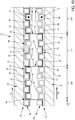
- the first radially outer fabric and the second radially inner fabric or knit serve as interfaces between the load-bearing elements and the radially outer and radially inner structures of revolution, respectively, which are therefore not in direct contact.
- an improved flattening of the tread is observed, in particular in a meridian plane, by an increase in the meridian radii of curvature at the level of the axial ends of the tread.
- H0x K ⁇ H ⁇ H0 which means that, in the absence of load applied to the tire and in the absence of pressure in the tire, the carrying wire portions of the supporting wire elements are in a collapsed state.
- the first structure of revolution comprises a first layer of a first polymeric composition
- the first fabric being impregnated at least in part with the first polymeric composition
- the second structure of revolution comprises a second layer of a second polymeric composition, the second fabric or knit being impregnated at least in part with the second polymeric composition.
- Each first and second polymeric composition makes it possible to ensure the physicochemical cohesion of the assembly with the other elements of the tire.
- each side having a curvilinear length L F is advantageously at least equal to 1.05 times, preferably 1.15 times the mean radial height H of the internal annular space.
- the curvilinear length L F of each flank is at least equal to 1.3 times and at most equal to 1.6 times the mean radial height H of the interior annular space.
- the sidewalls are not directly linked to the assembly and preferably are not directly linked to the supporting elements.
- the sidewalls participate in part in carrying the load, depending on their own structural rigidity. However, the sides have independent mechanical behavior and do not interfere with the mechanical behavior of the supporting structure.
- the sidewalls generally comprise at least one elastomeric material and may optionally comprise a reinforcement frame.
- the tire In the case of effective pressurization by an inflation gas, the tire then exhibits pneumatic rigidity, due to the pressure, which will also contribute to the carrying of the applied load.
- the pressure is at least equal to 0.5 bar, preferably at least equal to 1 bar. The higher the pressure, the greater the contribution of the pneumatic stiffness to the carrying of the applied load, and, correlatively, the greater the contribution of the structural rigidity of the load-bearing structure and / or of the sidewalls and / or of the first and second structures. of revolution at the port of the applied load is low.
- the tire comprises a structure of carcass revolution arranged radially between the first structure of revolution and the crown structure of revolution.
- the carcass structure of revolution extends continuously between each axial end of the second structure of revolution radially through each sidewall and axially over the entire axial width of the first structure of revolution.
- the carcass revolution structure comprises a carcass ply comprising carcass reinforcing elements substantially parallel to each other in a direction forming an angle greater than or equal to 65 °, preferably greater than or equal to at 80 ° and more preferably substantially equal to 90 ° with the circumferential direction of the tire.
- a structure of carcass revolution promotes the uniform deformation of the first fabric, and in the corresponding embodiments, the uniform deformation of the so-called deformable transverse straight zones. The inventors hypothesize that the deformation forces along the first general direction of the first fabric are, during the tire manufacturing process, transmitted along the first fabric by the carcass revolution structure.
- the crown structure of revolution comprises two working plies, each working ply comprising working reinforcing elements substantially parallel to each other in a direction forming an angle ranging from 15 ° to 40 °, preferably ranging from 20 °. ° at 30 ° with the circumferential direction of the tire, the working reinforcement elements being crossed from one working ply with respect to the other.
- the crown structure of revolution comprises a hooping ply comprising wire hooping reinforcing elements substantially parallel to each other forming an angle at most equal to 10 °, preferably ranging from 5 ° to 10 ° with the circumferential direction. of the tire.
- the hooping ply is arranged radially outside the working plies.
- each transverse straight zone of the second group of transverse straight zone (s) ) has a substantially zero elongation in the circumferential direction of the tire.
- each first chain wire element of each transverse straight zone of the second group of straight zone (s) ( s) transverse (s) has a substantially zero elongation in the circumferential direction of the tire.
- each first wire chain element of each transverse straight zone of the first group of transverse straight zone (s) is partially broken.
- the first wire member of each first chain wire element of each transverse straight zone of the first group of transverse straight zone (s) has a non-zero elongation in the first chain direction and is unbroken
- the second wire member of each first chain wire member of each transverse straight zone of the first group of transverse straight zone (s) is broken at at least one point along its length in at least at least one transverse straight zone of the first group of transverse straight zone (s), preferably in each transverse straight zone of the first group of transverse straight zone (s).
- each first wire chain element in each transverse straight zone of the second group of transverse straight zone (s) is unbroken.
- first wire member and the second wire member of each first chain wire member of each transverse straight zone of the second group of transverse straight zone (s) are unbroken.
- the elongation of each transverse straight zone of the first group of straight zone (s) ) transverse (s) in the first general direction is substantially equal to (2 ⁇ x H) / SLd1 with SLd1 being the sum of the lengths at rest Ld1 of all the transverse straight zones of the first group of transverse straight zone (s) (s).
- the elongation is measured in accordance with standard NF EN ISO 13934-1 of July 2013.
- each transverse straight zone of the first group of transverse straight zone (s) in the first general direction is substantially equal to ((2 ⁇ x H) + SLd1) / N with N being the number of transverse straight zones of the first group of transverse straight zone (s) included on the circumference of the tire and by circumferential winding of the first fabric around the main axis of revolution of the tire and SLd1 being the sum of the lengths at rest Ld1 of the transverse straight zones of the first group of transverse straight zone (s) in the first general direction.
- each transverse straight zone of the first group of transverse straight zone (s) being elongated and partially broken, the sum of the elongated lengths of each transverse straight zone of the first group of transverse straight zone (s) ( s) in the first general direction is substantially equal to ((2 ⁇ x H) + SLd1).
- each transverse straight zone of the second group of transverse straight zone (s) is substantially zero.
- the elongation is measured in accordance with standard NF EN ISO 13934-1 of July 2013.
- the length of each transverse straight zone of the second group of transverse straight zone (s) according to the first general direction is then substantially equal to the length at rest of each transverse straight zone of the second group of transverse straight zone (s).
- the conformation of the first fabric is obtained only by the elongation of the so-called deformable transverse straight zones of the first group of transverse straight zone (s) without contribution of any elongation or rupture of the so-called transverse straight zones. indeformable and unbreakable of the second group of transverse straight zone (s).
- each transverse straight zone of the second group of transverse straight zone (s) ( s) has a non-zero elongation along the circumferential direction of the tire, preferably an elongation along the circumferential direction of the tire at most equal to 20%, preferably 15%, and more preferably 10% of the elongation of each zone transverse line of the first group of transverse straight zone (s) along the circumferential direction of the tire.
- each first filamentary chain element of each transverse straight zone of the second group of transverse straight zone (s) exhibits a non-zero elongation in the circumferential direction of the tire, preferably an elongation in the circumferential direction of the tire at most equal at 20%, preferably at 15%, and more preferably at 10% of the elongation of each first wire chain element in each transverse straight zone of the first group of transverse straight zone (s) according to the circumferential direction of the tire.
- the first fabric comprising first wire elements, called weft, substantially parallel to each other and intersecting with the first warp wire elements, the first weft wire elements of each transverse straight zone of the first group of zone (s) transverse straight line (s) have a two-by-two spacing in the circumferential direction of the tire greater than the two-by-two spacing in the circumferential direction of the tire between the first weft wire elements of each transverse straight zone of the second group of transverse straight zone (s).
- two-by-two spacing along the circumferential direction of the tire is meant the deviation along the circumferential direction of the tire between each pair of adjacent wire elements.
- each wire anchoring portion is not broken.
- each wire anchoring portion has a substantially zero elongation in the circumferential direction of the tire.
- each wire anchoring portion has a non-zero elongation in the circumferential direction of the tire.
- each transverse straight zone of the first group of transverse straight zone (s) alternates, according to the circumferential direction of the tire, with a transverse straight zone of the second group of transverse straight zone (s) (s) ( s).
- the first chain direction and the circumferential direction of the tire form a substantially zero angle.
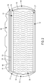
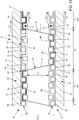
- the assembly extends circumferentially over at most one complete turn around the main axis so that the first structure of revolution forms an axially continuous cylindrical winding of the assembly between the two sidewalls of the tire.
- at most one full turn is used, that is to say at least one turn but less than two full turns.
- the junction between the two ends of the assembly can be made by overlapping or butt jointing.
- the first chain direction and the circumferential direction of the tire form a substantially non-zero angle less than 10 °, preferably a substantially non-zero angle less than or equal to 5 °
- the assembly extends circumferentially over several complete turns around the main axis so that the first structure of revolution forms an axially discontinuous helical winding of the assembly between the two sidewalls. of the tire.
- the assembly is wound over several complete turns without it being necessary to join the two ends of the assembly.
- each circumferential end of each transverse straight zone of the first group of straight zone (s) ( s) transverse (s) of one turn is axially substantially aligned with each circumferential end of each transverse straight zone of the first group of transverse straight zone (s) of each adjacent tower.
- each circumferential end of each transverse straight zone of the first group of straight zone (s) ( s) transverse (s) of a turn is located between the axial extensions of the two circumferential ends of each transverse straight zone of the first group of transverse straight zone (s) of each adjacent turn.
- the deformable areas and the non-deformable and unbreakable areas are distributed axially.
- certain ends circumferential of certain transverse straight zones of the first group of transverse straight zone (s) of one turn are axially substantially aligned with circumferential ends of at least one transverse straight zone of the first group of zone (s) transverse straight line (s) of each adjacent tower and certain circumferential ends of certain transverse straight zones of the first group of transverse straight zone (s) of a tower lie between the axial extensions of the two ends circumferential of certain transverse straight zones of the first group of transverse straight zone (s) of each adjacent tower.
- the subject of the invention is a mounted assembly comprising a tire as defined above, the tire being mounted on a mounting means of the assembly mounted on a vehicle.
- the mounting means is for example a rim.
- the mounting means comprises a face cooperating with an external face of the tire according to the invention.
- the two cooperating faces are maintained in contact with one another, for example by gluing or else by the pressure forces resulting from the inflation of the tire.
- H0 x K ⁇ H ⁇ H0 which means that, in the absence of load applied to the tire and in the absence of pressure in the tire, the supporting wire elements are in a folded state.
- the first fabric is deformed under a relatively low stress which makes it possible, during the tire manufacturing process, to use a suitable conformation stress that does not run the risk of damaging the blank.
- a force is exerted on the first fabric, in the circumferential direction of the building cylinder, less than the force necessary for break the first wire member of each first wire chain element.
- a force is exerted on the first fabric, in the circumferential direction of the building cylinder greater than or equal to the necessary force. to cause at least one breakage of the second wire member of each first wire chain element.
- no transverse straight zone of the second group is extended in the circumferential direction of the building cylinder. of transverse straight zone (s).
- transverse straight zones of the second group of non-deformable transverse straight zone no first wire chain element is extended in the circumferential direction of the building cylinder in each zone.
- transverse line of the second group of zone (s) transverse straight line (s).
- each transverse straight zone of the second group of zones is extended in the circumferential direction of the building cylinder. transverse line (s).
- each first wire chain element is lengthened in the circumferential direction of the building cylinder in each transverse straight zone. of the second group of transverse straight zone (s).
- each first wire chain element is partially broken in each transverse straight zone of the first group of transverse straight zone (s).
- the first is lengthened without breaking wire member of each first wire chain element in the first chain direction of each transverse straight zone of the first group of transverse straight zone (s) and the second wire member is broken each first wire chain element d '' at least one transverse straight zone of the first group of transverse straight zone (s) at at least one point of its length on the transverse straight zone of the first group of transverse straight zone (s) (s) ( s), preferably the second wire member of each first wire chain element of each transverse straight zone of the first group of transverse straight zone (s) is broken at at least one point along its length on each zone transverse line of the first group of zone (s) transverse straight line (s).
- no first wire chain element is broken in each transverse straight zone of the second group of transverse straight zone (s).
- substantially no first wire member and no second wire member of each first chain wire member of each transverse straight zone of the second group of transverse straight zone (s) are not broken.
- substantially none it is meant that one does not break and / or that one does not lengthen any cord organ or an insufficient number of cord organs of chain or with an insignificant elongation to participate in the conformation of the first tissue .
- the first fabric comprising first wire elements, called weft elements, substantially parallel to each other and intersecting with the first wire chain elements, the first wire frame elements are separated in pairs in the circumferential direction of the making cylinder. of each transverse straight zone of the first group of transverse straight zone (s) and the gap is maintained in pairs in the circumferential direction of the preparation cylinder between the first weft wire elements of each transverse straight zone of the second group of transverse straight zone (s).
- no first wire anchoring portion is substantially broken.
- no first wire anchoring portion is extended in the circumferential direction of the building cylinder.
- each first wire anchoring portion is lengthened in the circumferential direction of the building cylinder.
- substantially none is meant that no first wired anchoring portion or an insufficient number of first wired anchoring portions or else with an insignificant elongation to participate in is not broken and / or extended. the conformation of the first tissue.
- each transverse straight zone of the first group of transverse straight zone (s) alternates, in the circumferential direction, with a transverse straight zone of the second group of transverse straight zone (s) ).
- the first chain direction and the circumferential direction of the building cylinder form a substantially zero angle.
- the assembly is wound circumferentially over at most one complete turn around the main axis so that the first structure of revolution forms an axially continuous helical winding of the assembly between the two sidewalls of the tire.
- the first chain direction and the circumferential direction of the building cylinder form a substantially non-zero angle less than 10 °, preferably a substantially non-zero angle less than or equal to 5 °.
- the assembly is wound circumferentially over several complete turns around the main axis so that the first structure of revolution forms an axially discontinuous cylindrical winding of the assembly between the two sides of the assembly. pneumatic.
- the assembly is wound so that each circumferential end of each transverse straight zone of the first group of transverse straight zone (s) of one turn is axially substantially aligned with each circumferential end of each transverse straight zone of the first group of transverse straight zone (s) of each adjacent turn.
- the assembly is wound so that each circumferential end of each transverse straight zone of the first group of transverse straight zone (s) of one turn is located between the axial extensions of the two circumferential ends of each transverse straight zone of the first group of transverse straight zone (s) of each adjacent turn.
- the assembly is wound so that certain circumferential ends of certain transverse straight zones of the first group of transverse straight zone (s) of a turn are axially substantially aligned with circumferential ends of at least one transverse straight zone of the first group of transverse straight zone (s) of each adjacent turn and so that certain circumferential ends of certain transverse straight zones of the first group of transverse straight zone (s) of a turn lie between the axial extensions of the two circumferential ends of certain transverse straight zones of the first group of transverse straight zone (s) of each adjacent tower.
- a carcass revolution structure is wound radially outside the first revolution structure.
- each axial end of the second revolution structure is continuously connected by the carcass revolution structure extending radially through each sidewall and axially over the entire axial width of the first structure of revolution.
- the internal annular space is formed by pressurization with a gas for inflating the internal annular space.
- a crown structure of revolution is wound radially outside the first fabric, and preferably radially outside of the carcass structure of revolution.
- a tread is wound radially outside the first fabric, preferably radially outside the crown structure of revolution.
- a reference X, Y, Z corresponding to the usual orientations respectively axial (in the direction YY '), radial (in the direction ZZ') and circumferential (in the direction XX ') of a tire.
- the axes ZZ 'and XX' define the median circumferential plane of the tire.
- the tire 20 is substantially of revolution about a main axis substantially parallel to the axial direction YY '.
- the tire 20 is here intended for a passenger vehicle.
- the tire 20 is mounted on a mounting means 22, here a rim, thus forming a mounted assembly 23 according to the invention for a vehicle.
- the tire 20 comprises a first structure of revolution 25 and a second structure of revolution 27.
- the second structure of revolution 27 is arranged radially inside the first structure of revolution 25.
- These first and second structures of revolution 25, 27 form part of an impregnated assembly 21 described in more detail below.
- the first structure of revolution 25 comprises a first structure 10 of wire elements, here a first fabric 26, and a first layer 33 of a first polymeric composition 34, the first fabric 26 being impregnated at least in part with the first composition polymer 34.
- the second structure of revolution 27 comprises a second structure 12 of wire elements, here a second fabric or knit 28 and preferably a fabric 28, and a second layer 35 of a second polymeric composition 36, the second fabric 28 being impregnated at least in part with the second polymeric composition 36.
- the second structure 27 comprises a knitted fabric impregnated at least in part with the second polymeric composition 36.
- first fabric 26 is arranged radially on the outside with respect to the second fabric 28.
- Each first and second polymeric composition 34, 36 comprises for example an elastomeric composition comprising at least one elastomer, preferably diene, for example natural rubber.
- the impregnated assembly 21 comprises an assembly 24 comprising the first and second impregnated fabrics 26, 28, each first and second impregnated fabric 26, 28 respectively forming each first and second structures of revolution 25, 27.
- the assembly 24 also comprises a structure carrier 30 comprising wire carrier elements 32 connecting the first and second fabrics 26, 28 to each other.
- the supporting structure 30 here consists of a plurality of supporting wire elements 32 all identical.
- the tire 20 comprises a carcass revolution structure 51 and a crown revolution structure 55.
- the carcass revolution structure 51 is arranged radially between the first revolution structure 25 and the crown revolution structure 55.
- the carcass revolution structure 51 comprises a carcass ply 53 comprising carcass reinforcement elements substantially parallel to each other in a direction forming an angle greater than or equal to 65 °, preferably greater than or equal to 80 ° and here more preferably substantially equal to 90 ° with the circumferential direction XX 'of the tire 20.
- the reinforcing elements are textile filament reinforcing elements, for example comprising two strands of 144 tex polyester wrapped 290 turns together.
- the crown revolution structure 55 arranged radially on the outside of the carcass revolution structure 51 comprises two working plies 54, 56.
- Each working ply 54, 56 comprises working reinforcing elements substantially parallel to each other. in a direction forming an angle ranging from 15 ° to 40 °, preferably ranging from 20 ° to 30 ° with the circumferential direction of the tire and here equal to 26 °.
- the working reinforcement elements are crossed by one working ply 54, 56 with respect to the other.
- the working reinforcement elements are metallic wire reinforcement elements, for example cables of 2x0.30 mm structure.
- the crown structure of revolution 55 also comprises a hooping ply 57 arranged radially outside the working plies 54, 56.
- the hooping ply 57 comprises wire hooping reinforcement elements substantially parallel to each other forming an angle. at most equal to 10 °, preferably ranging from 5 ° to 10 ° with the circumferential direction of the tire 10 and here equal to 5 °.
- the hooping reinforcement elements are textile filament reinforcement elements, for example comprising two strands of aramid of 167 tex wound at 315 turns together.
- the tire 20 also includes a tread 58 as illustrated in the figures 1 , 2 and 4 arranged radially outside the crown structure 55.
- the carcass structure of revolution 51 comprises a radially inner face 59 and the tread 58 comprises a radially outer face 60.
- Each carcass 53, working 54, 56 and hooping 57 ply comprises a polymeric composition, for example an elastomeric composition comprising at least one elastomer, preferably diene, for example natural rubber, in which are embedded the corresponding reinforcing elements .
- the tread 58 is intended to come into contact with a ground.
- the tread 58 consists of a polymeric composition, for example an elastomeric composition comprising at least one elastomer, preferably diene, for example natural rubber.
- the first structure of revolution 25, the second structure of revolution 27, the carcass structure 51, the crown structure of revolution 55 and the tread 58 have a common axis of revolution, in this case the axis of rotation YY 'of tire 20.
- the first revolution structure 25 has an inner face 42 and an outer face 43 as well as two axial ends 44.
- the inner face 42 is an inner face of the first fabric 26 and the outer face 43 is an outer face of the first layer 33.
- the first fabric 26 also comprises an external face 41 arranged radially, within the tire 20, outside the internal face 42. Within the tire 20, the internal face 42 is arranged radially inside the external face 43 and the external face 43 is in contact with the radially inner face 59 of the carcass structure 51 of revolution.
- the second structure of revolution 27 has an inner face 46 and an outer face 47 as well as two axial ends 48.
- the inner face 46 is an inner face of the second fabric 28 and the outer face 47 is an outer face of the second layer 35.
- the second fabric 28 also comprises an external face 49 arranged radially, within the tire 20, inside the internal face 46. Within the tire 20, the internal face 46 is arranged radially outside the external face. 47.
- each surface 42, 46 describes a cylinder of revolution about the axis YY 'of the tire 20.
- the tire 20 also comprises two sidewalls 50.
- Each sidewall 50 interconnects each axial end 44 of the first structure of revolution 25 and each axial end 48 of the second structure of revolution 27.
- the structure of revolution of the carcass 51 extends. continuously between each axial end 48 of the second structure of revolution 27 radially through each sidewall 50 and axially over the entire axial width of the first structure of revolution 25.
- the tire 20 also comprises an internal annular space 52 delimited on the one hand radially, by each internal face 42 and 46 and, on the other hand axially, by the two sides 50.
- the internal annular space 52 forms a closed cavity capable of being pressurized by an inflation gas, for example air.
- the supporting elements 32 are two by two independent in the internal annular space 52.
- the assembly 24 extends circumferentially over at most one complete turn around the main axis of the tire 20 so that the first structure of revolution 25 forms an axially continuous cylindrical winding of the tire. assembly 24 between the two sidewalls 50 of the tire 20 as illustrated in figure 5 .
- the tire 20 is shown subjected to a nominal radial load Z N.
- the tire 20 is in contact with a flat ground by a contact surface A, having a circumferential length X A.
- the supporting elements 32 connected to the portion of the first structure of revolution 25 in contact with the ground via the tread, are subjected to compressive buckling, while at least part of the supporting elements 32, connected to the portion of the first structure of revolution 25 not in contact with the ground, are in tension.
- the tire 20 illustrated on figure 3 is inflated to a pressure P of between 1.5 bar and 2.5 bars and is subjected to a radial load Z N equal to 600 daN.
- the first fabric 26 comprises two longitudinal edges 26A and 26B.
- the first fabric 26 extends in a first general direction G1 substantially parallel to each longitudinal edge 26A, 26B.
- the first fabric 26 comprises first wire elements 64, called first warp wire elements, and first wire elements 66, called first weft wire elements.
- the first wire chain elements 64 of the first fabric 26 are substantially parallel to each other and extend in a first direction known as the chain C1, substantially parallel to the first general direction G1.
- the first weft wire elements 66 of the first fabric 26 are substantially parallel to each other and extend in a first so-called weft direction T1 and intersect with the first wire chain elements 64.
- the first wire chain elements 64 s' extend continuously along the entire length of the first fabric 26.
- the second fabric 28 comprises two longitudinal edges 28A and 28B.
- the second fabric 28 extends in a second general direction G2 substantially parallel to each longitudinal edge 28A, 28B.
- the second general direction G2 is substantially parallel to the first general direction G1.
- the second fabric 28 comprises second wire elements 68, called second wire warp elements, and second wire elements 70, called second weft wire elements.
- the second wire chain elements 68 of the second fabric 28 are substantially parallel to each other and extend in a second direction called chain C2, substantially parallel to the second general direction G2.
- the second weft wire elements 70 of the second fabric 28 are substantially parallel to each other and extend in a second so-called weft direction T2 and intersect with the second wire chain elements 68.
- the second wire chain elements 68 s' extend continuously along the entire length of the first fabric 28.
- each first and second fabric 26, 28 the warp and weft directions form with each other an angle ranging from 70 ° to 90 °. In this case, the angle is substantially equal to 90 °.
- each first and second chain direction forms an angle less than or equal to 10 ° with the circumferential direction XX 'of the tire 20.
- each first and second chain direction forms an angle substantially zero with the circumferential direction XX 'of the tire 20.
- Each wire element 64, 66, 68, 70 is a textile wire element.
- each first wire chain member 64 comprises first and second wire members 65, 67.
- the second wire member 67 is substantially rectilinear and the first wire member 65 is helically wound around the second wire member 67.
- Each first and second wire member 65, 67 comprises, independently of one another, at least one multifilament strand comprising several monofilaments each consisting of a material chosen from a polyester, a polyamide, a polyketone, a polyurethane, a natural fiber, a mineral fiber, preferably chosen from a polyester, a polyamide, a polyketone, a polyurethane, a natural fiber and an assembly of these materials, more preferably chosen from a polyester, a natural fiber and an assembly of these materials.
- the first filament member 65 comprises at least one multifilament strand comprising several monofilaments each consisting of a material chosen from a polyester, a polyamide, a polyketone, a polyurethane, a natural fiber, preferably chosen from a polyester, a polyamide, a polyketone. , a polyurethane and an assembly of these materials, more preferably chosen from polyesters and assemblies of polyesters.
- the first wire member 65 is a PET multifilament strand having a titer equal to 110 tex.
- the second filamentary member 67 comprises at least one multifilament strand comprising several monofilaments each consisting of a material chosen from a polyester, a polyamide, a polyketone, a natural fiber, a mineral fiber, preferably chosen from a polyester, a polyamide, a polyketone and a fiber natural and an assembly of these materials, more preferably in rayon.
- the second wire member 67 is an assembly of two multifilament strands of 11.5 tex each.
- each wire element 66, 68, 70 is a spun wire element having a linear density equal to 170 tex and a tenacity equal to 66 cN / tex.
- Each wire carrier element 32 alternately extends from the first fabric 26 to the second fabric 28 and from the second fabric 28 to the first fabric 26 as one moves along the wire carrier element 32.
- Each wire carrier element 32 is a textile support wire element, here made of polyethylene terephthalate (PET).
- PET polyethylene terephthalate
- each carrier element 32 is a spun wire element having a linear density equal to 55 tex and a tenacity equal to 54 cN / tex.
- Each wire carrier element 32 comprises a wire carrier portion 74 extending between the first and second fabrics 26, 28, in particular between the internal faces 42 and 46.
- Each wire carrier element 32 comprises first and second wire anchoring portions 76, 78 of the carrier wire element 32 respectively in the first fabric 26 and the second fabric 28.
- Each first and second anchoring wire portion 76, 78 extends the carrier portion 74 respectively in each first fabric 26 and second fabric 28.
- Each first and second wire anchoring portion 76, 78 is interwoven with each first fabric 26 and second fabric 28, respectively.
- Each first and second wire anchoring portion 76, 78 is wound at least in part around respectively at least a first element wire 64, 66 of the first fabric 26 and at least a second wire element 68, 70 of the second fabric 28.
- each wire anchoring portion 76, 78 connects two wire portions res carriers 74 between them and each wire carrier portion 74 connects two wire anchoring portions 76, 78 between them.
- each first wire anchoring portion 76 is wound at least in part around at least a first weft wire element 66 of the first fabric 26 and here, preferably, around at least two first wire elements of frame 66 adjacent in the first general direction G1.
- each second wire anchoring portion 78 is wound at least in part around at least one second weft wire member 68 of the second fabric 28, preferably around at least two second weft wire members 66 adjacent according to the second general direction G2.
- Each first and second wire anchoring portion 76, 78 extends in a direction substantially parallel to the first and second respectively.
- Each first wire anchoring portion 76 passes alternately from face 41 to face 42 between two first wire weft elements 66 adjacent around which the first wire anchoring portion 76 is wound.
- each second wire anchoring portion 78 passes alternately from face 46 to face 49 between two second wire frame elements 68 adjacent around which second wire anchoring portion 78 is wound.
- the first fabric 26 comprises transverse straight zones Z1 of a first group of transverse straight zones, each transverse straight zone Z1 having a length at rest Ld1 in the first general direction G1 and extending over the entire width of the first fabric 26 This length Ld1 is the same for all the transverse straight zones Z1 here equal to 7.9 mm. All the transverse straight zones Z1 of the first group of transverse straight zones are identical.
- the first fabric 26 also comprises transverse straight zones Z2 of a second group of transverse straight zones, each transverse straight zone Z2 having a length at rest Ld2 in the first general direction G1 and extending over the entire width of the first fabric 26 This length Ld2 is the same for all the transverse straight zones Z2 is here equal to 5.8 mm. All the transverse straight zones Z2 of the second group of transverse straight zones are identical.
- Each transverse straight zone Z1 of the first group of transverse straight zones alternates, in the first general direction or in the circumferential direction XX ', with a transverse straight zone Z2 of the second group of transverse straight zones.
- the sum of the lengths at rest Ld1 and Ld2 of all the transverse straight zones along the first general direction G1 is substantially equal to L.
- the sum SLd1 of the lengths at rest Ld1 of the transverse straight zones Z1 is equal to 975 mm and the sum of the lengths at rest Ld2 of the transverse straight zones Z2 is equal to 717 mm.
- the first fabric thus comprises 123 entire transverse straight zones Z1 and Z2 as well as an incomplete transverse straight zone Z2.
- the internal face 42 of the first fabric 26 and the internal face 46 of the second fabric 28 are spaced apart by a straight distance H0 when each carrying wire portion 74 is at rest.
- H0 47 mm.
- H also represents the H the average radial height of the internal annular space 52 in the absence of load applied to the tire 20 and in the absence of pressure in the tire 20.
- the first radially outer revolution structure 25 has an average radius R1 equal to 313 mm and the second radially inner revolution structure 27 has a average radius R2 equal to 268 mm.
- the wire carrier portion 74 has a circular mean section S P , defined by a smaller characteristic dimension E and a larger characteristic dimension D both equal, in the example presented , to the diameter of the circle, and characterized by its aspect ratio R equal to D / E, therefore equal to 1 in the present case.
- the smallest characteristic dimension E of the mean section S P of the carrying wire portion 74 that is to say, in the present case, its diameter, is at most equal to 0.02 times the mean radial height H of the interior annular space 52.
- the carrying portion 74 has a length at rest L P at least equal to the average height H of the interior annular space 52.
- the wire anchoring portions 76, 78 have the same average section S P circular and the same smallest characteristic dimension E of the mean section S P.
- Each wire carrier element 32 has an average section S P equal to 7 * 10 -8 m 2 and a breaking stress F r / S P equal to 470 MPa.
- the average surface density D of the supporting wire portions 74 per unit area of the first structure of revolution 25 and per unit of area of the second structure of revolution 27 is equal to 85,000 wires / m 2 .
- the breaking force Fr is here equal to 33 N.
- the first fabric 26 is arranged so that, for any non-zero stress, expressed in N, less than or equal to (P0 x (L / 2 ⁇ + H) xl) / 2 exerted on the first fabric 26 according to the first general direction G1, the first wire member 65 of each first wire member 64 of the chain has a non-zero elongation in the first general direction G1 over at least part of its length and is unbroken.
- the first fabric 26 is also arranged so that, the stress exerted on the first fabric 26 in the first general direction G1 necessary, expressed in N, to cause at least one rupture of the second wire member 67 of each first wire element 64 of the chain is less than or equal to (P0 x (L / 2 ⁇ + H) xl) / 2.
- the first fabric 26 is arranged so that, for any lengthening of the first fabric 26 in the first general direction G1 less than or equal to (2 ⁇ x H) / L, the first fabric 26 develops a force, expressed in N, according to the first general direction G1 less than or equal to (P0 x (L / 2 ⁇ + H) xl) / 2.
- This stress value, here 1232 N represents the stress below which the first tissue elongates without breaking in the first general direction G1 to allow conformation.
- the stress necessary to break the second wire member 67 of each first wire chain element 64 is determined under the conditions of standard NF EN ISO 13934-1 of July 2013.
- this constraint is the force corresponding to the first drop of the force-elongation curve and here equal to 1408 N and therefore much less than or equal to 3460 N.
- the stress necessary to break the first wire member of each first wire chain element is the force corresponding to the second drop of the force-elongation curve and here equal to 11000 N and therefore much greater than 3460 N.
- each transverse straight zone Z1 is devoid of any first wire anchoring portion 76 over the entire width l of the first fabric 26.
- each transverse straight zone Z1 is arranged so as to, for any non-zero stress less than or equal to ( P0 x (L / 2 ⁇ + H) xl) / 2 exerted on the first fabric 26 according to the first general direction G1, and for any elongation of the first fabric 26 according to the first general direction G1 less than or equal to (2 ⁇ x H) / L, allow an elongation with partial rupture of each transverse straight zone Z1 in the first general direction G1.
- each transverse straight zone Z1 is arranged so that, in each straight zone transverse Z1, on the one hand allow a separation of the weft wire elements 66 with respect to each other in the first general direction G1, on the other hand, allow an elongation without breaking the first wire member 65 of each first wire element of chain 64 in the first general direction G1 and finally cause at least one breakage of the second wire member 67 of each first chain wire element 64 in each transverse straight zone Z1, that is to say a partial rupture of each first wire element chain 64 in each transverse straight zone Z1, for any non-zero stress less than or equal to (PO x (L / 2 ⁇ + H) x I) / 2 exerted on the first fabric 26 in the first general direction G1 and for any lengthening of the first fabric 26 in the first general direction G1 less than or equal to (2 ⁇ x H) / L.
- each transverse straight zone Z1 is said to be deformable.
- each transverse straight zone Z2 comprises at least a first anchoring wire portion 76 over the width of the first fabric 26.
- each transverse straight zone Z2 is arranged so as to, for any lower non-zero stress or equal to (PO x (L / 2 ⁇ + H) x I) / 2 exerted on the first fabric 26 according to the first general direction G1, and for any elongation of the first fabric 26 according to the first general direction G1 less than or equal to ( 2 ⁇ x H) / L, prevent an elongation of each transverse straight zone Z2 in the first general direction G1 and a rupture of each transverse straight zone Z2.
- each transverse straight zone Z2 is arranged so as to prevent, in each transverse straight zone Z2, on the one hand an elongation of each first wire chain element 64 in the first general direction G1, on the other hand, a rupture of the first wire member 65 of each first wire chain element 64, a rupture of the second wire member 67 of each first wire chain element 64, that is to say a rupture of each first wire chain element 64, and finally, a spacing of the first wire frame elements 66 relative to each other in the first general direction G1, for any non-zero stress less than or equal to (PO x (L / 2 ⁇ + H) x I) / 2 exerted on the first fabric 26 according to the first general direction G1 and for any elongation of the first fabric 26 according to the first general direction G1 less than or equal to (2 ⁇ x H) / L.
- each straight zone tra nsversale Z2 is said to be undeformable and is also here unbreakable.
- Each transverse straight zone Z2 is also arranged so as to prevent, on the one hand, an elongation of each first wire anchoring portion 76 in the first general direction G1 and, on the other hand, a rupture of each first wire anchoring portion. 76, and this, under a constraint at most equal to (PO x (L / 2 ⁇ + H) x I) / 2 exerted on the first fabric 26 according to the first general direction G1 and for any elongation of the first fabric 26 according to the first general direction G1 less than or equal to (2 ⁇ x H) / L.
- the first weft wire elements 66 of each transverse straight zone Z1 have a two by two spacing in the circumferential direction XX 'greater than the two by two spacing in the circumferential direction XX' between the first weft wire elements 66 of each transverse straight zone Z2.
- the first fabric 26 is arranged so that, for a length at rest L of the first fabric 26 according to the first general direction G1, expressed in m, for any elongation of the first fabric 26 according to the first general direction G1 less than or equal to ( 2 ⁇ x H) / L, the first wire member 65 has a non-zero elongation and is unbroken.
- the first fabric 26 is arranged so that there is an elongation of the first fabric 26 in the first general direction G1 less than or equal to (2 ⁇ x H) / L from which the second wire member 67 is broken.
- the first member 65 has a non-zero elongation and is unbroken as illustrated in figure 8C .
- the second wire member breaks for an elongation of the first chain wire element equal to 13.8% corresponding to an elongation of the first fabric 26 equal to 8%, elongation of the first fabric 26 much less than or equal to (2 ⁇ x H) / L.
- the second cord member 67 is broken as illustrated in figure 8C .
- the first wire member 65 of each first wire chain element 64 has, at least over part of its length, a non-zero elongation in the first chain direction C1 and is not broken.
- the second wire member 67 of each first wire chain element 64 is broken at at least one point along its length.
- each transverse straight zone Z1 has a non-zero elongation in the circumferential direction XX 'and is partially broken while each transverse straight zone Z2 exhibits substantially zero elongation in the circumferential direction and is unbroken.
- the first wire member 65 of each first wire chain element 64 of each transverse straight zone Z1 has a non-zero elongation in the first chain direction C1 and is not broken.
- the second wire member 67 of each first wire chain element 64 of each transverse straight zone Z1 is broken at at least one point along its length in at least one transverse straight zone Z1.
- each first wire element 64de chain of each transverse straight zone Z1 is partially broken.
- each wire anchoring portion 76 has a substantially zero elongation in the circumferential direction XX 'and is unbroken.
- each transverse straight zone Z1 called deformable having to compensate for the substantially zero elongation of each transverse straight zone Z2 called indeformable and unbreakable, the elongation at maximum force of each transverse straight zone Z1 of the first group of straight zone (s) (s) ) transverse (s) according to the first general direction verifies Art1> (2 ⁇ x H) / SLd1 with SLd1 being the sum of the lengths at rest of all the transverse straight zones Z1 called deformable.
- each transverse straight zone Z1 called deformable has an elongated length La1 substantially equal to ((2 ⁇ x H) + SLd1) / N with N being the number of transverse straight zones Z1 called deformable on the circumference of the tire and by circumferential winding of the tire.
- Each so-called deformable transverse straight zone Z1 therefore has an elongation in the first general direction G1 equal to 29%, much less than the elongation at maximum force Art1 measured, according to standard EN ISO 13934-1 of July 2013, at 60% (To be verified).
- the elongation at break Arc of each first wireframe element 64 of the chain satisfies Arc> (2 ⁇ x H) / SLd1.
- the elongation at break Arc measured according to the ASTM D885 / D885 MA standard of January 2010 is here equal to 60%, a value much greater than 29%.
- each first and second fabric 26, 28 is impregnated respectively with the first and second polymeric compositions 34, 36 so as to form, during a step of winding the assembly 21 (described below) the first structure of revolution 25 and the second structure of revolution 27.
- each carrying wire portion 74 is in a folded or flexed state.
- FIG. 19 there is a building cylinder 80 whose diameter is equal to that of the mounting means on which the tire 20 is intended to be mounted.
- the building cylinder 80 is substantially of revolution about an axis of revolution coaxial with the axis of revolution YY 'of the tire 20.
- an assembly 82 comprising the carcass structure 51 and the sidewalls 50 is placed on the building cylinder 80.
- the impregnated assembly 21 is wound up from the figure 11 so that the first chain direction C1 and the circumferential direction of the building cylinder 80, here substantially coincident with the circumferential direction XX 'of the tire 20, form an angle less than or equal to 10 ° and, in this first embodiment, a substantially zero angle.
- the impregnated assembly 21 is wound circumferentially over at most one complete turn around the main axis so that the first structure of revolution 25 forms an axially continuous cylindrical winding of the impregnated assembly 21. between the two sidewalls of the tire 20.
- the axially continuous cylindrical winding has an axial width greater than or equal to 50%, preferably 75%, to the axial width of the tread 58.
- the assembly impregnated 21 is deposited in a single cylindrical winding turn.
- laying in full width since the axial width referred to the impregnated assembly 21 is obtained in a single cylindrical winding turn.
- the advantage of full width laying is manufacturing productivity.
- laying in full width necessarily implies the existence of at least one overlap zone, or weld, in the circumferential direction, between the circumferential ends of the impregnated assembly 21, in particular at the end of winding.
- each axial end 44 of the first structure of revolution 25 and each axial end 48 of the second structure of revolution 27 are connected together. by one of the sidewalls 50 so as to constitute the internal annular space 52.
- the carcass structure 51 is also disposed radially outside the first structure of revolution 25 by folding the two axial ends 84 of the assembly 82
- Each axial end 48 of the second structure of revolution 27 is then connected continuously by the structure of revolution of the carcass 51 which extends radially through each sidewall 50 and axially over the entire axial width of the first structure of revolution 25.
- each transverse straight zone Z1 is lengthened in the circumferential direction XX 'of the building cylinder 80 and each transverse straight zone Z1 is partially broken, here each first wire chain element 64 is partially broken according to the first chain direction C1 of each transverse straight zone Z1.
- the first wire member 65 of each first wire member 64 of the chain is lengthened without breaking along the first chain direction C1 of each transverse straight zone Z1 and the second wire member 65 of each first wire member 64 is completely broken.
- chain of each transverse straight zone Z1 at at least one point of its length on the transverse straight zone Z1.
- one does not lengthen in the circumferential direction XX 'of the building cylinder 80 and one does not substantially break any transverse straight zone Z2, in this case one does not extend or break any first wire element 64 of the chain. no transverse straight zone Z2.
- no first wire member 65 and no second wire member 67 of each first wire member 64 of the chain of each transverse straight zone Z2 are not lengthened in the first chain direction and are substantially not broken.
- the first weft wire elements 66 are separated in pairs in the circumferential direction XX' from each transverse straight zone Z1 and are maintained the two-by-two spacing in the circumferential direction XX 'of the first weft wire elements 66 of each transverse straight zone Z2.
- the internal annular space 52 is formed by deployment of the internal annular space 52 by pressurization with a gas for inflating the internal annular space 52, for example air.
- a force is exerted on the first fabric 26, in the circumferential direction XX ', equal to 2076 N and therefore less than the force necessary to break the first wire member 65 of each first wire chain element 64, here equal to 11000 N.
- a force is exerted on the first fabric 26, in the circumferential direction XX ', equal to 2076 N and therefore greater than or equal to the force necessary to cause at least one breakage of the second wire member 67 of each first wire chain element 64, here equal to 1408 N.
- the diameter of the first fabric 26 and of the first structure of revolution 25 of the tire 20 increases while the diameter of the second structure of radially revolution 27 of the tire 20, and therefore of the second fabric 28, remains substantially constant.
- the radial distance from the axis of revolution YY 'of the tire 20 of the first fabric 26 increases significantly during shaping as does its circumferential length, an increase absorbed by the elongation of the first fabric 26 in accordance with the invention. .
- the radial distance from the axis of revolution YY ′ of the tire 20 of the second fabric 28 remains substantially constant during shaping and its circumferential length does not vary substantially. We then obtain the assembly according to the invention shown in figure 19 .
- the tire 20 is then obtained in the green state, shown diagrammatically on the figure 14 comprising the impregnated assembly shown on figure 12 .
- the tire 20 is crosslinked, for example by vulcanization, in order to obtain the tire 20 in the cured state.
- the first chain direction and the circumferential direction XX 'of the tire 20 form a substantially non-zero angle less than 10 °, preferably a substantially non-zero angle less than or equal to 5 ° and here equal at 5 °.
- the assembly 24 extends circumferentially over several complete turns around the main axis so that the first structure of revolution 25 forms an axially discontinuous helical winding of the assembly 24 between the two sidewalls 50 of the tire 20.
- the impregnated assembly 21 is wound around the axis of the tire 20 so as to form the helical winding of an assembly strip 92, the axial portions 94 of the strip 92 being axially juxtaposed.
- strip is meant an impregnated assembly 21 having a limited axial width, at most equal to 30% of the axial width of the tread 58, and of great length at least equal to twice the circumference of the tread 58 , so that the strip to be applied can be stored in the form of a roll.
- Such a strip is thus unwound according to a helix, having for axis of revolution the axis of revolution of the tire 20.
- the number of helical winding turns of the strip is determined by the total axial width of the helical winding referred to and by the density of carrier elements 32.
- the installation of the strip may be contiguous, that is to say that the portions of the strip are in contact two by two by their axial edges, or not contiguous, that is to say that the axial edges of the axial portions 94 of the strip are spaced apart by a substantially non-zero space.
- the advantage of laying in a strip is the absence of overlap zones, or welds, in the circumferential direction, between axial portions of the strip, at the end of winding.
- the connecting surface S E of the outer face 43 of the first structure of revolution 25 with the radially inner face 59 of the crown structure of revolution 55 is the sum of the connecting surfaces of the axial portions 94 of strip 92 juxtaposed.
- the impregnated assembly 21 is helically wound around the axis of revolution of the tire 20 so that, before shaping, the first chain direction and the circumferential direction of the building cylinder form a substantially non-zero angle of less than 10 °, of preferably a substantially non-zero angle of less than 5 °.
- each transverse straight zone Z1 called deformable has an elongated length La1 substantially equal to ((2 ⁇ x H) + SLd1) / N with N being the number of transverse straight zones Z1 called deformable on the circumference of the tire and by circumferential winding of the first fabric around the main axis YY 'of revolution of the tire 20, here equal to 10.22 mm.
- Each so-called deformable transverse straight zone Z1 therefore has an elongation in the first general direction G1 equal to 29%.
- the impregnated assembly 21 is wound up so that each circumferential end W of each transverse straight zone Z1 of the first group of transverse straight zone (s) by one turn is situated between the axial extensions of the two ends circumferential W of each transverse straight zone Z1 of each adjacent turn.
- transverse straight zones Z2 are deformable.
- Such transverse straight zones Z2 would be arranged so as to allow an elongation of each transverse straight zone Z2, preferably at most equal to 20%, preferably to 15%, and more preferably to 10% of the elongation of each straight zone transverse Z1 of the first group of transverse straight zone (s) according to the first general direction G1, for example by allowing an elongation of each first wire chain element 64 according to the first general direction G1 in each transverse straight zone Z2, preferably so as to allow an elongation of each first wire chain element 64 in the first general direction G1 in each transverse straight zone Z2 at most equal to 20%, preferably to 15%, and more preferably to 10% of the lengthening of each first wire element of chain 64 in the first general direction G1 in each transverse straight zone Z1.
- each transverse straight zone Z2 would be arranged so as to allow each first wire anchoring portion 76 to be lengthened in the first general direction G1.
- each transverse straight zone Z2 is arranged so as to allow a separation of the first weft wire elements from one another in the first general direction G1 in each transverse straight zone Z2.
- each transverse straight zone Z2 exhibits a non-zero elongation in the circumferential direction XX 'of the tire 20, preferably a non-zero elongation at most equal to 20%, preferably at 15%, and more preferably at 10%, of the elongation of each transverse straight zone Z1 along the circumferential direction XX 'of the tire 20, for example because each first cord element 64 of each straight zone transverse Z2 has a non-zero elongation in the circumferential direction XX 'of the tire 20, preferably because each first wire chain element 64 of each transverse straight zone Z2 has an elongation in the circumferential direction XX' at most equal to 20%, of preferably at 15%, and more preferably at 10% of the elongation of each first wire chain element 64 according to the first directi on general G1 in each transverse straight zone Z1.
- each first wire anchoring portion 76 has
- each first wire anchoring portion 76 is lengthened in the circumferential direction XX 'of the building cylinder.
Landscapes
- Engineering & Computer Science (AREA)
- Mechanical Engineering (AREA)
- Textile Engineering (AREA)
- Chemical & Material Sciences (AREA)
- Composite Materials (AREA)
- Tires In General (AREA)
- Laminated Bodies (AREA)
- Moulding By Coating Moulds (AREA)
- Tyre Moulding (AREA)
- Knitting Of Fabric (AREA)
- Woven Fabrics (AREA)
Applications Claiming Priority (2)
| Application Number | Priority Date | Filing Date | Title |
|---|---|---|---|
| FR1750287A FR3061674A1 (fr) | 2017-01-12 | 2017-01-12 | Assemblage comprenant un tissu partiellement rompable et une structure porteuse |
| PCT/FR2018/050056 WO2018130783A1 (fr) | 2017-01-12 | 2018-01-10 | Assemblage comprenant un tissu partiellement rompable et une structure porteuse |
Publications (2)
| Publication Number | Publication Date |
|---|---|
| EP3568290A1 EP3568290A1 (fr) | 2019-11-20 |
| EP3568290B1 true EP3568290B1 (fr) | 2021-01-06 |
Family
ID=58669945
Family Applications (1)
| Application Number | Title | Priority Date | Filing Date |
|---|---|---|---|
| EP18702755.2A Active EP3568290B1 (fr) | 2017-01-12 | 2018-01-10 | Assemblage comprenant un tissu partiellement rompable et une structure porteuse |
Country Status (6)
| Country | Link |
|---|---|
| US (1) | US11331953B2 (enExample) |
| EP (1) | EP3568290B1 (enExample) |
| JP (1) | JP7324143B2 (enExample) |
| CN (1) | CN110300655B (enExample) |
| FR (1) | FR3061674A1 (enExample) |
| WO (1) | WO2018130783A1 (enExample) |
Families Citing this family (14)
| Publication number | Priority date | Publication date | Assignee | Title |
|---|---|---|---|---|
| FR3061675A1 (fr) | 2017-01-12 | 2018-07-13 | Compagnie Generale Des Etablissements Michelin | Assemblage comprenant une structure rompable et une structure porteuse |
| FR3088237B3 (fr) | 2018-11-09 | 2020-10-23 | Michelin & Cie | Procede de fabrication anti-relaxation d'un pneumatique |
| WO2020094979A1 (fr) * | 2018-11-09 | 2020-05-14 | Compagnie Generale Des Etablissements Michelin | Dispositif de type pneumatique à éléments filaires souples pour véhicule |
| FR3090498A3 (fr) * | 2018-12-24 | 2020-06-26 | Michelin & Cie | Assemblage pour un pneumatique, pneumatique et procédés de fabrication associés |
| FR3090497B3 (fr) * | 2018-12-24 | 2020-12-04 | Michelin & Cie | Assemblage pour un pneumatique, pneumatique et procédés de fabrication associés |
| FR3098441B1 (fr) | 2019-07-11 | 2021-07-16 | Michelin & Cie | Assemblage comprenant un tissu partiellement rompable et une structure porteuse |
| FR3098440B1 (fr) | 2019-07-11 | 2021-07-16 | Michelin & Cie | Assemblage comprenant un tissu déformable plastiquement et une structure porteuse |
| FR3102082B1 (fr) | 2019-10-18 | 2021-10-22 | Michelin & Cie | Assemblage comprenant un tissu à âme fusible et une structure porteuse |
| FR3103733B1 (fr) * | 2019-11-29 | 2022-08-19 | Michelin & Cie | Assemblage comprenant une structure porteuse adaptable |
| FR3103732B1 (fr) * | 2019-11-29 | 2023-03-31 | Michelin & Cie | Assemblage comprenant une structure porteuse adaptable |
| KR102327709B1 (ko) * | 2020-02-17 | 2021-11-19 | 한국타이어앤테크놀로지 주식회사 | 보강구조부를 포함하는 비공기입 타이어 |
| CN113306345A (zh) * | 2021-03-16 | 2021-08-27 | 龙岩高德新材料科技有限公司 | 一种实心轮胎及其制作工艺 |
| FR3124526B1 (fr) * | 2021-06-24 | 2023-06-30 | Michelin & Cie | Panneau conformable comprenant deux faces reliées par une structure de liaison uniforme |
| FR3124532B1 (fr) | 2021-06-24 | 2023-06-30 | Michelin & Cie | Panneau conformable comprenant deux faces reliées par une structure de liaison non uniforme |
Family Cites Families (39)
| Publication number | Priority date | Publication date | Assignee | Title |
|---|---|---|---|---|
| GB542379A (en) * | 1940-04-20 | 1942-01-07 | William Yarworth Jones | Improvements in or relating to reinforced plastic materials |
| CA1064805A (en) * | 1976-05-07 | 1979-10-23 | Henri J. Mirtain | Method for making a radial ply tire in a single building stage |
| WO1980000069A1 (en) * | 1978-06-16 | 1980-01-24 | Goodyear Tire & Rubber | A composite reinforcement cord for reinforcing elastomeric articles |
| US4248286A (en) | 1978-06-30 | 1981-02-03 | The Goodyear Tire & Rubber Company | Safety support assembly for pneumatic tires |
| US4235270A (en) | 1978-06-30 | 1980-11-25 | The Goodyear Tire & Rubber Company | Tire with supporting and cushioning walls |
| DE3902940A1 (de) * | 1989-02-01 | 1990-08-02 | Parabeam Bv | Doppelplueschgewebe |
| US4945962A (en) * | 1989-06-09 | 1990-08-07 | The Uniroyal Goodrich Tire Company | Honeycomb non-pneumatic tire with a single web on one side |
| JPH05321077A (ja) * | 1992-05-20 | 1993-12-07 | Tominaga Kikai Seisakusho:Kk | 粗構造立体織物とその製織方法 |
| US5840399A (en) * | 1996-11-05 | 1998-11-24 | Kozel; John A. | Construction of articles of manufacture of fiber reinforced structural composites |
| US6460588B1 (en) * | 1997-09-26 | 2002-10-08 | The Goodyear Tire & Rubber Company | Pen reinforcement for rubber composites |
| FR2778369A1 (fr) | 1998-05-06 | 1999-11-12 | Michelin & Cie | Pneumatique a armature de carcasse a deux rigidites |
| US6561245B1 (en) * | 1998-07-10 | 2003-05-13 | The Goodyear Tire & Rubber Company | Thread reinforcement means for extended mobility tire |
| FR2786131A1 (fr) * | 1998-11-20 | 2000-05-26 | Michelin Soc Tech | Membrane de soutien de bande de roulement |
| US6983776B2 (en) * | 1999-12-10 | 2006-01-10 | Michelin Recherche Et Technique S.A. | Structurally supported resilient tire with bias ply carcass |
| US7650919B2 (en) * | 1999-12-10 | 2010-01-26 | Michelin Recherche of Technique S.A. | Non-pneumatic tire having web spokes |
| US7013939B2 (en) * | 2001-08-24 | 2006-03-21 | Michelin Recherche Et Technique S.A. | Compliant wheel |
| DE60131469T2 (de) * | 2001-08-24 | 2008-09-18 | Société de Technologie Michelin | Nicht- pneumatischer reifen |
| US6935393B2 (en) * | 2003-10-23 | 2005-08-30 | The Goodyear Tire & Rubber Company | Tire having an overlay for noise improvement |
| CA2563036A1 (en) * | 2004-04-27 | 2005-11-03 | Toyo Tire & Rubber Co., Ltd. | Run-flat tire support, manufacturing method therefor, and a run-flat tire with the run-flat tire support fixedly mounted thereto |
| FR2922159B1 (fr) | 2007-10-15 | 2011-04-29 | Michelin Soc Tech | Pneumatique a virole et a structure porteuse |
| FR2928865B1 (fr) | 2008-03-19 | 2010-03-19 | Michelin Soc Tech | Roue elastique non pneumatique |
| JP5033070B2 (ja) * | 2008-06-23 | 2012-09-26 | 東洋ゴム工業株式会社 | 非空気圧タイヤの製造方法 |
| JP5968222B2 (ja) * | 2009-08-28 | 2016-08-10 | ナンリン ハン, | シート物品およびファスナカバーを使用する方法 |
| FR2953761B1 (fr) | 2009-12-10 | 2012-04-13 | Michelin Soc Tech | Pneumatique pour vehicules lourds comportant une couche d'elements de renforcement circonferentiels constituee d'une partie centrale et de deux parties axialement exterieures |
| RU2519576C2 (ru) * | 2010-03-12 | 2014-06-20 | Компани Женераль Дез Этаблиссман Мишлен | Конструктивно поддерживаемое непневматическое колесо с узлом непрерывного контура |
| FR2978769B1 (fr) | 2011-08-04 | 2013-09-27 | Michelin Soc Tech | Composition adhesive aqueuse a base de polyaldehyde et de polyphenol |
| FR2978770B1 (fr) | 2011-08-04 | 2013-09-27 | Michelin Soc Tech | Composition adhesive aqueuse a base de polyaldehyde et phloroglucinol |
| FR2978771B1 (fr) | 2011-08-04 | 2013-09-27 | Michelin Soc Tech | Composition adhesive aqueuse a base de polyaldehyde et 2,2', 4,4'-tetrahydroxydiphenyl sulfide |
| US20140216625A1 (en) * | 2013-02-06 | 2014-08-07 | Milliken & Company | Pneumatic tire carcass having air blocking stabilizing fabric system |
| FR3008707B1 (fr) | 2013-07-16 | 2017-11-10 | Michelin & Cie | Composition adhesive aqueuse a base d'aldehyde biosource et de polyphenol |
| FR3025529B1 (fr) * | 2014-09-10 | 2017-07-14 | Aircelle Sa | Preforme pour raidisseur composite courbe pour piece axisymetrique telle qu’une virole |
| US9849734B2 (en) * | 2014-10-31 | 2017-12-26 | The Goodyear Tire & Rubber Company | Pneumatic tire with a three dimensional component |
| FR3031931B1 (fr) | 2015-01-22 | 2017-02-03 | Michelin & Cie | Dispositif de type pneumatique pour vehicule |
| FR3031932B1 (fr) * | 2015-01-22 | 2017-02-03 | Michelin & Cie | Dispositif de type pneumatique pour vehicule |
| FR3045462B1 (fr) | 2015-12-17 | 2017-12-29 | Michelin & Cie | Ensemble pour pneumatique comprenant des tissu(s) ou tricot(s) impregnes et un moyen de maintien sacrificiel |
| FR3045463B1 (fr) | 2015-12-17 | 2017-12-29 | Michelin & Cie | Assemblage pour pneumatique comprenant des tissu(s) ou tricot(s) comprenant des elements filaires pre-encolles |
| JP2017190130A (ja) * | 2016-04-13 | 2017-10-19 | ザ・グッドイヤー・タイヤ・アンド・ラバー・カンパニー | 剪断バンド及び非空気式タイヤ |
| US20180154694A1 (en) * | 2016-12-01 | 2018-06-07 | The Goodyear Tire & Rubber Company | Lightweight tire assembly |
| FR3061675A1 (fr) | 2017-01-12 | 2018-07-13 | Compagnie Generale Des Etablissements Michelin | Assemblage comprenant une structure rompable et une structure porteuse |
-
2017
- 2017-01-12 FR FR1750287A patent/FR3061674A1/fr not_active Ceased
-
2018
- 2018-01-10 EP EP18702755.2A patent/EP3568290B1/fr active Active
- 2018-01-10 WO PCT/FR2018/050056 patent/WO2018130783A1/fr not_active Ceased
- 2018-01-10 JP JP2019537820A patent/JP7324143B2/ja active Active
- 2018-01-10 CN CN201880012444.3A patent/CN110300655B/zh active Active
- 2018-01-10 US US16/477,729 patent/US11331953B2/en active Active
Non-Patent Citations (1)
| Title |
|---|
| None * |
Also Published As
| Publication number | Publication date |
|---|---|
| JP2020519476A (ja) | 2020-07-02 |
| CN110300655B (zh) | 2021-05-14 |
| US20190366772A1 (en) | 2019-12-05 |
| JP7324143B2 (ja) | 2023-08-09 |
| CN110300655A (zh) | 2019-10-01 |
| FR3061674A1 (fr) | 2018-07-13 |
| WO2018130783A1 (fr) | 2018-07-19 |
| EP3568290A1 (fr) | 2019-11-20 |
| US11331953B2 (en) | 2022-05-17 |
Similar Documents
| Publication | Publication Date | Title |
|---|---|---|
| EP3568290B1 (fr) | Assemblage comprenant un tissu partiellement rompable et une structure porteuse | |
| EP3568289B1 (fr) | Assemblage comprenant une structure élastique et une structure porteuse | |
| EP3568291B1 (fr) | Assemblage pour pneumatique comprenant une structure rompable et une structure porteuse, pneumatique et procédé de fabrication dudit pneu | |
| EP3390114B1 (fr) | Ensemble pour pneumatique comprenant des tissu(s) ou tricot(s) imprégnés et un moyen de maintien sacrificiel | |
| EP3390115B1 (fr) | Assemblage pour pneumatique comprenant des tissu(s) ou tricot(s) comprenant des éléments filaires pré-encollés | |
| WO2015000836A1 (fr) | Pneumatique comprenant un tissu à entrelacement | |
| EP1565328B1 (fr) | Pneumatique a mobilite etendue avec flancs ondules | |
| EP1578620B1 (fr) | Pneumatique a mobilite etendue avec flancs a rigidite variable | |
| EP3877199B1 (fr) | Procede de fabrication d'un pneumatique | |
| WO2021105625A1 (fr) | Assemblage comprenant une structure porteuse adaptable | |
| EP3996903B1 (fr) | Assemblage comprenant un tissu déformable plastiquement et une structure porteuse | |
| EP4045298B1 (fr) | Assemblage comprenant un tissu à âme fusible et une structure porteuse | |
| EP3877165B1 (fr) | Procede de fabrication anti-relaxation d'un pneumatique | |
| EP3996904B1 (fr) | Assemblage comprenant un tissu partiellement rompable et une structure porteuse | |
| EP4065357B1 (fr) | Assemblage comprenant une structure porteuse adaptable | |
| WO2024200361A1 (fr) | Armatures de carcasse de pneumatique pour avion | |
| FR3112311A1 (fr) | Pneumatique pour véhicule de tourisme |
Legal Events
| Date | Code | Title | Description |
|---|---|---|---|
| STAA | Information on the status of an ep patent application or granted ep patent |
Free format text: STATUS: UNKNOWN |
|
| STAA | Information on the status of an ep patent application or granted ep patent |
Free format text: STATUS: THE INTERNATIONAL PUBLICATION HAS BEEN MADE |
|
| PUAI | Public reference made under article 153(3) epc to a published international application that has entered the european phase |
Free format text: ORIGINAL CODE: 0009012 |
|
| STAA | Information on the status of an ep patent application or granted ep patent |
Free format text: STATUS: REQUEST FOR EXAMINATION WAS MADE |
|
| 17P | Request for examination filed |
Effective date: 20190812 |
|
| AK | Designated contracting states |
Kind code of ref document: A1 Designated state(s): AL AT BE BG CH CY CZ DE DK EE ES FI FR GB GR HR HU IE IS IT LI LT LU LV MC MK MT NL NO PL PT RO RS SE SI SK SM TR |
|
| AX | Request for extension of the european patent |
Extension state: BA ME |
|
| DAV | Request for validation of the european patent (deleted) | ||
| DAX | Request for extension of the european patent (deleted) | ||
| REG | Reference to a national code |
Ref country code: DE Ref legal event code: R079 Ref document number: 602018011616 Country of ref document: DE Free format text: PREVIOUS MAIN CLASS: B29D0030020000 Ipc: B29C0070240000 |
|
| GRAP | Despatch of communication of intention to grant a patent |
Free format text: ORIGINAL CODE: EPIDOSNIGR1 |
|
| STAA | Information on the status of an ep patent application or granted ep patent |
Free format text: STATUS: GRANT OF PATENT IS INTENDED |
|
| RIC1 | Information provided on ipc code assigned before grant |
Ipc: B29C 70/24 20060101AFI20200721BHEP Ipc: B29D 30/06 20060101ALI20200721BHEP Ipc: B60C 17/04 20060101ALI20200721BHEP Ipc: B60C 9/18 20060101ALI20200721BHEP Ipc: B60C 17/00 20060101ALI20200721BHEP Ipc: B29D 30/02 20060101ALI20200721BHEP Ipc: B60C 3/02 20060101ALI20200721BHEP |
|
| INTG | Intention to grant announced |
Effective date: 20200821 |
|
| GRAS | Grant fee paid |
Free format text: ORIGINAL CODE: EPIDOSNIGR3 |
|
| GRAA | (expected) grant |
Free format text: ORIGINAL CODE: 0009210 |
|
| STAA | Information on the status of an ep patent application or granted ep patent |
Free format text: STATUS: THE PATENT HAS BEEN GRANTED |
|
| AK | Designated contracting states |
Kind code of ref document: B1 Designated state(s): AL AT BE BG CH CY CZ DE DK EE ES FI FR GB GR HR HU IE IS IT LI LT LU LV MC MK MT NL NO PL PT RO RS SE SI SK SM TR |
|
| REG | Reference to a national code |
Ref country code: GB Ref legal event code: FG4D Free format text: NOT ENGLISH |
|
| REG | Reference to a national code |
Ref country code: AT Ref legal event code: REF Ref document number: 1351902 Country of ref document: AT Kind code of ref document: T Effective date: 20210115 Ref country code: CH Ref legal event code: EP |
|
| REG | Reference to a national code |
Ref country code: DE Ref legal event code: R096 Ref document number: 602018011616 Country of ref document: DE |
|
| REG | Reference to a national code |
Ref country code: IE Ref legal event code: FG4D Free format text: LANGUAGE OF EP DOCUMENT: FRENCH |
|
| REG | Reference to a national code |
Ref country code: NL Ref legal event code: MP Effective date: 20210106 |
|
| REG | Reference to a national code |
Ref country code: AT Ref legal event code: MK05 Ref document number: 1351902 Country of ref document: AT Kind code of ref document: T Effective date: 20210106 |
|
| REG | Reference to a national code |
Ref country code: LT Ref legal event code: MG9D |
|
| PG25 | Lapsed in a contracting state [announced via postgrant information from national office to epo] |
Ref country code: LT Free format text: LAPSE BECAUSE OF FAILURE TO SUBMIT A TRANSLATION OF THE DESCRIPTION OR TO PAY THE FEE WITHIN THE PRESCRIBED TIME-LIMIT Effective date: 20210106 Ref country code: PT Free format text: LAPSE BECAUSE OF FAILURE TO SUBMIT A TRANSLATION OF THE DESCRIPTION OR TO PAY THE FEE WITHIN THE PRESCRIBED TIME-LIMIT Effective date: 20210506 Ref country code: NO Free format text: LAPSE BECAUSE OF FAILURE TO SUBMIT A TRANSLATION OF THE DESCRIPTION OR TO PAY THE FEE WITHIN THE PRESCRIBED TIME-LIMIT Effective date: 20210406 Ref country code: BG Free format text: LAPSE BECAUSE OF FAILURE TO SUBMIT A TRANSLATION OF THE DESCRIPTION OR TO PAY THE FEE WITHIN THE PRESCRIBED TIME-LIMIT Effective date: 20210406 Ref country code: FI Free format text: LAPSE BECAUSE OF FAILURE TO SUBMIT A TRANSLATION OF THE DESCRIPTION OR TO PAY THE FEE WITHIN THE PRESCRIBED TIME-LIMIT Effective date: 20210106 Ref country code: GR Free format text: LAPSE BECAUSE OF FAILURE TO SUBMIT A TRANSLATION OF THE DESCRIPTION OR TO PAY THE FEE WITHIN THE PRESCRIBED TIME-LIMIT Effective date: 20210407 Ref country code: HR Free format text: LAPSE BECAUSE OF FAILURE TO SUBMIT A TRANSLATION OF THE DESCRIPTION OR TO PAY THE FEE WITHIN THE PRESCRIBED TIME-LIMIT Effective date: 20210106 |
|
| PG25 | Lapsed in a contracting state [announced via postgrant information from national office to epo] |
Ref country code: LV Free format text: LAPSE BECAUSE OF FAILURE TO SUBMIT A TRANSLATION OF THE DESCRIPTION OR TO PAY THE FEE WITHIN THE PRESCRIBED TIME-LIMIT Effective date: 20210106 Ref country code: PL Free format text: LAPSE BECAUSE OF FAILURE TO SUBMIT A TRANSLATION OF THE DESCRIPTION OR TO PAY THE FEE WITHIN THE PRESCRIBED TIME-LIMIT Effective date: 20210106 Ref country code: RS Free format text: LAPSE BECAUSE OF FAILURE TO SUBMIT A TRANSLATION OF THE DESCRIPTION OR TO PAY THE FEE WITHIN THE PRESCRIBED TIME-LIMIT Effective date: 20210106 Ref country code: AT Free format text: LAPSE BECAUSE OF FAILURE TO SUBMIT A TRANSLATION OF THE DESCRIPTION OR TO PAY THE FEE WITHIN THE PRESCRIBED TIME-LIMIT Effective date: 20210106 Ref country code: SE Free format text: LAPSE BECAUSE OF FAILURE TO SUBMIT A TRANSLATION OF THE DESCRIPTION OR TO PAY THE FEE WITHIN THE PRESCRIBED TIME-LIMIT Effective date: 20210106 |
|
| REG | Reference to a national code |
Ref country code: CH Ref legal event code: PL |
|
| PG25 | Lapsed in a contracting state [announced via postgrant information from national office to epo] |
Ref country code: IS Free format text: LAPSE BECAUSE OF FAILURE TO SUBMIT A TRANSLATION OF THE DESCRIPTION OR TO PAY THE FEE WITHIN THE PRESCRIBED TIME-LIMIT Effective date: 20210506 Ref country code: LU Free format text: LAPSE BECAUSE OF NON-PAYMENT OF DUE FEES Effective date: 20210110 |
|
| REG | Reference to a national code |
Ref country code: BE Ref legal event code: MM Effective date: 20210131 |
|
| REG | Reference to a national code |
Ref country code: DE Ref legal event code: R097 Ref document number: 602018011616 Country of ref document: DE |
|
| PG25 | Lapsed in a contracting state [announced via postgrant information from national office to epo] |
Ref country code: SM Free format text: LAPSE BECAUSE OF FAILURE TO SUBMIT A TRANSLATION OF THE DESCRIPTION OR TO PAY THE FEE WITHIN THE PRESCRIBED TIME-LIMIT Effective date: 20210106 Ref country code: EE Free format text: LAPSE BECAUSE OF FAILURE TO SUBMIT A TRANSLATION OF THE DESCRIPTION OR TO PAY THE FEE WITHIN THE PRESCRIBED TIME-LIMIT Effective date: 20210106 Ref country code: CZ Free format text: LAPSE BECAUSE OF FAILURE TO SUBMIT A TRANSLATION OF THE DESCRIPTION OR TO PAY THE FEE WITHIN THE PRESCRIBED TIME-LIMIT Effective date: 20210106 Ref country code: MC Free format text: LAPSE BECAUSE OF FAILURE TO SUBMIT A TRANSLATION OF THE DESCRIPTION OR TO PAY THE FEE WITHIN THE PRESCRIBED TIME-LIMIT Effective date: 20210106 |
|
| PLBE | No opposition filed within time limit |
Free format text: ORIGINAL CODE: 0009261 |
|
| STAA | Information on the status of an ep patent application or granted ep patent |
Free format text: STATUS: NO OPPOSITION FILED WITHIN TIME LIMIT |
|
| PG25 | Lapsed in a contracting state [announced via postgrant information from national office to epo] |
Ref country code: RO Free format text: LAPSE BECAUSE OF FAILURE TO SUBMIT A TRANSLATION OF THE DESCRIPTION OR TO PAY THE FEE WITHIN THE PRESCRIBED TIME-LIMIT Effective date: 20210106 Ref country code: SK Free format text: LAPSE BECAUSE OF FAILURE TO SUBMIT A TRANSLATION OF THE DESCRIPTION OR TO PAY THE FEE WITHIN THE PRESCRIBED TIME-LIMIT Effective date: 20210106 Ref country code: CH Free format text: LAPSE BECAUSE OF NON-PAYMENT OF DUE FEES Effective date: 20210131 Ref country code: DK Free format text: LAPSE BECAUSE OF FAILURE TO SUBMIT A TRANSLATION OF THE DESCRIPTION OR TO PAY THE FEE WITHIN THE PRESCRIBED TIME-LIMIT Effective date: 20210106 Ref country code: LI Free format text: LAPSE BECAUSE OF NON-PAYMENT OF DUE FEES Effective date: 20210131 |
|
| 26N | No opposition filed |
Effective date: 20211007 |
|
| PG25 | Lapsed in a contracting state [announced via postgrant information from national office to epo] |
Ref country code: ES Free format text: LAPSE BECAUSE OF FAILURE TO SUBMIT A TRANSLATION OF THE DESCRIPTION OR TO PAY THE FEE WITHIN THE PRESCRIBED TIME-LIMIT Effective date: 20210106 Ref country code: IE Free format text: LAPSE BECAUSE OF NON-PAYMENT OF DUE FEES Effective date: 20210110 Ref country code: AL Free format text: LAPSE BECAUSE OF FAILURE TO SUBMIT A TRANSLATION OF THE DESCRIPTION OR TO PAY THE FEE WITHIN THE PRESCRIBED TIME-LIMIT Effective date: 20210106 |
|
| PG25 | Lapsed in a contracting state [announced via postgrant information from national office to epo] |
Ref country code: SI Free format text: LAPSE BECAUSE OF FAILURE TO SUBMIT A TRANSLATION OF THE DESCRIPTION OR TO PAY THE FEE WITHIN THE PRESCRIBED TIME-LIMIT Effective date: 20210106 |
|
| PG25 | Lapsed in a contracting state [announced via postgrant information from national office to epo] |
Ref country code: IT Free format text: LAPSE BECAUSE OF FAILURE TO SUBMIT A TRANSLATION OF THE DESCRIPTION OR TO PAY THE FEE WITHIN THE PRESCRIBED TIME-LIMIT Effective date: 20210106 |
|
| PG25 | Lapsed in a contracting state [announced via postgrant information from national office to epo] |
Ref country code: IS Free format text: LAPSE BECAUSE OF FAILURE TO SUBMIT A TRANSLATION OF THE DESCRIPTION OR TO PAY THE FEE WITHIN THE PRESCRIBED TIME-LIMIT Effective date: 20210506 |
|
| PG25 | Lapsed in a contracting state [announced via postgrant information from national office to epo] |
Ref country code: BE Free format text: LAPSE BECAUSE OF NON-PAYMENT OF DUE FEES Effective date: 20210131 |
|
| GBPC | Gb: european patent ceased through non-payment of renewal fee |
Effective date: 20220110 |
|
| PG25 | Lapsed in a contracting state [announced via postgrant information from national office to epo] |
Ref country code: GB Free format text: LAPSE BECAUSE OF NON-PAYMENT OF DUE FEES Effective date: 20220110 |
|
| PG25 | Lapsed in a contracting state [announced via postgrant information from national office to epo] |
Ref country code: NL Free format text: LAPSE BECAUSE OF NON-PAYMENT OF DUE FEES Effective date: 20210206 Ref country code: CY Free format text: LAPSE BECAUSE OF FAILURE TO SUBMIT A TRANSLATION OF THE DESCRIPTION OR TO PAY THE FEE WITHIN THE PRESCRIBED TIME-LIMIT Effective date: 20210106 |
|
| PG25 | Lapsed in a contracting state [announced via postgrant information from national office to epo] |
Ref country code: HU Free format text: LAPSE BECAUSE OF FAILURE TO SUBMIT A TRANSLATION OF THE DESCRIPTION OR TO PAY THE FEE WITHIN THE PRESCRIBED TIME-LIMIT; INVALID AB INITIO Effective date: 20180110 |
|
| PG25 | Lapsed in a contracting state [announced via postgrant information from national office to epo] |
Ref country code: MK Free format text: LAPSE BECAUSE OF FAILURE TO SUBMIT A TRANSLATION OF THE DESCRIPTION OR TO PAY THE FEE WITHIN THE PRESCRIBED TIME-LIMIT Effective date: 20210106 |
|
| PG25 | Lapsed in a contracting state [announced via postgrant information from national office to epo] |
Ref country code: TR Free format text: LAPSE BECAUSE OF FAILURE TO SUBMIT A TRANSLATION OF THE DESCRIPTION OR TO PAY THE FEE WITHIN THE PRESCRIBED TIME-LIMIT Effective date: 20210106 |
|
| PG25 | Lapsed in a contracting state [announced via postgrant information from national office to epo] |
Ref country code: MT Free format text: LAPSE BECAUSE OF FAILURE TO SUBMIT A TRANSLATION OF THE DESCRIPTION OR TO PAY THE FEE WITHIN THE PRESCRIBED TIME-LIMIT Effective date: 20210106 |
|
| PGFP | Annual fee paid to national office [announced via postgrant information from national office to epo] |
Ref country code: DE Payment date: 20250121 Year of fee payment: 8 |
|
| PGFP | Annual fee paid to national office [announced via postgrant information from national office to epo] |
Ref country code: FR Payment date: 20250127 Year of fee payment: 8 |