EP3568211B1 - Stromgetriebene vorrichtung für eine persönliche atemschutzvorrichtung - Google Patents
Stromgetriebene vorrichtung für eine persönliche atemschutzvorrichtung Download PDFInfo
- Publication number
- EP3568211B1 EP3568211B1 EP18703109.1A EP18703109A EP3568211B1 EP 3568211 B1 EP3568211 B1 EP 3568211B1 EP 18703109 A EP18703109 A EP 18703109A EP 3568211 B1 EP3568211 B1 EP 3568211B1
- Authority
- EP
- European Patent Office
- Prior art keywords
- blower
- wearer
- pressure
- personal protection
- breath
- Prior art date
- Legal status (The legal status is an assumption and is not a legal conclusion. Google has not performed a legal analysis and makes no representation as to the accuracy of the status listed.)
- Active
Links
Images









Classifications
-
- A—HUMAN NECESSITIES
- A62—LIFE-SAVING; FIRE-FIGHTING
- A62B—DEVICES, APPARATUS OR METHODS FOR LIFE-SAVING
- A62B18/00—Breathing masks or helmets, e.g. affording protection against chemical agents or for use at high altitudes or incorporating a pump or compressor for reducing the inhalation effort
- A62B18/006—Breathing masks or helmets, e.g. affording protection against chemical agents or for use at high altitudes or incorporating a pump or compressor for reducing the inhalation effort with pumps for forced ventilation
-
- A—HUMAN NECESSITIES
- A61—MEDICAL OR VETERINARY SCIENCE; HYGIENE
- A61M—DEVICES FOR INTRODUCING MEDIA INTO, OR ONTO, THE BODY; DEVICES FOR TRANSDUCING BODY MEDIA OR FOR TAKING MEDIA FROM THE BODY; DEVICES FOR PRODUCING OR ENDING SLEEP OR STUPOR
- A61M16/00—Devices for influencing the respiratory system of patients by gas treatment, e.g. ventilators; Tracheal tubes
- A61M16/0003—Accessories therefor, e.g. sensors, vibrators, negative pressure
- A61M16/0009—Accessories therefor, e.g. sensors, vibrators, negative pressure with sub-atmospheric pressure, e.g. during expiration
-
- A—HUMAN NECESSITIES
- A61—MEDICAL OR VETERINARY SCIENCE; HYGIENE
- A61M—DEVICES FOR INTRODUCING MEDIA INTO, OR ONTO, THE BODY; DEVICES FOR TRANSDUCING BODY MEDIA OR FOR TAKING MEDIA FROM THE BODY; DEVICES FOR PRODUCING OR ENDING SLEEP OR STUPOR
- A61M16/00—Devices for influencing the respiratory system of patients by gas treatment, e.g. ventilators; Tracheal tubes
- A61M16/0057—Pumps therefor
- A61M16/0066—Blowers or centrifugal pumps
-
- A—HUMAN NECESSITIES
- A61—MEDICAL OR VETERINARY SCIENCE; HYGIENE
- A61M—DEVICES FOR INTRODUCING MEDIA INTO, OR ONTO, THE BODY; DEVICES FOR TRANSDUCING BODY MEDIA OR FOR TAKING MEDIA FROM THE BODY; DEVICES FOR PRODUCING OR ENDING SLEEP OR STUPOR
- A61M16/00—Devices for influencing the respiratory system of patients by gas treatment, e.g. ventilators; Tracheal tubes
- A61M16/0057—Pumps therefor
- A61M16/0066—Blowers or centrifugal pumps
- A61M16/0069—Blowers or centrifugal pumps the speed thereof being controlled by respiratory parameters, e.g. by inhalation
-
- A—HUMAN NECESSITIES
- A61—MEDICAL OR VETERINARY SCIENCE; HYGIENE
- A61M—DEVICES FOR INTRODUCING MEDIA INTO, OR ONTO, THE BODY; DEVICES FOR TRANSDUCING BODY MEDIA OR FOR TAKING MEDIA FROM THE BODY; DEVICES FOR PRODUCING OR ENDING SLEEP OR STUPOR
- A61M16/00—Devices for influencing the respiratory system of patients by gas treatment, e.g. ventilators; Tracheal tubes
- A61M16/021—Devices for influencing the respiratory system of patients by gas treatment, e.g. ventilators; Tracheal tubes operated by electrical means
- A61M16/022—Control means therefor
-
- A—HUMAN NECESSITIES
- A61—MEDICAL OR VETERINARY SCIENCE; HYGIENE
- A61M—DEVICES FOR INTRODUCING MEDIA INTO, OR ONTO, THE BODY; DEVICES FOR TRANSDUCING BODY MEDIA OR FOR TAKING MEDIA FROM THE BODY; DEVICES FOR PRODUCING OR ENDING SLEEP OR STUPOR
- A61M16/00—Devices for influencing the respiratory system of patients by gas treatment, e.g. ventilators; Tracheal tubes
- A61M16/06—Respiratory or anaesthetic masks
-
- A—HUMAN NECESSITIES
- A61—MEDICAL OR VETERINARY SCIENCE; HYGIENE
- A61M—DEVICES FOR INTRODUCING MEDIA INTO, OR ONTO, THE BODY; DEVICES FOR TRANSDUCING BODY MEDIA OR FOR TAKING MEDIA FROM THE BODY; DEVICES FOR PRODUCING OR ENDING SLEEP OR STUPOR
- A61M16/00—Devices for influencing the respiratory system of patients by gas treatment, e.g. ventilators; Tracheal tubes
- A61M16/06—Respiratory or anaesthetic masks
- A61M16/0683—Holding devices therefor
-
- A—HUMAN NECESSITIES
- A61—MEDICAL OR VETERINARY SCIENCE; HYGIENE
- A61M—DEVICES FOR INTRODUCING MEDIA INTO, OR ONTO, THE BODY; DEVICES FOR TRANSDUCING BODY MEDIA OR FOR TAKING MEDIA FROM THE BODY; DEVICES FOR PRODUCING OR ENDING SLEEP OR STUPOR
- A61M16/00—Devices for influencing the respiratory system of patients by gas treatment, e.g. ventilators; Tracheal tubes
- A61M16/10—Preparation of respiratory gases or vapours
- A61M16/105—Filters
- A61M16/106—Filters in a path
- A61M16/1065—Filters in a path in the expiratory path
-
- A—HUMAN NECESSITIES
- A61—MEDICAL OR VETERINARY SCIENCE; HYGIENE
- A61M—DEVICES FOR INTRODUCING MEDIA INTO, OR ONTO, THE BODY; DEVICES FOR TRANSDUCING BODY MEDIA OR FOR TAKING MEDIA FROM THE BODY; DEVICES FOR PRODUCING OR ENDING SLEEP OR STUPOR
- A61M16/00—Devices for influencing the respiratory system of patients by gas treatment, e.g. ventilators; Tracheal tubes
- A61M16/10—Preparation of respiratory gases or vapours
- A61M16/105—Filters
- A61M16/106—Filters in a path
- A61M16/107—Filters in a path in the inspiratory path
-
- A—HUMAN NECESSITIES
- A62—LIFE-SAVING; FIRE-FIGHTING
- A62B—DEVICES, APPARATUS OR METHODS FOR LIFE-SAVING
- A62B18/00—Breathing masks or helmets, e.g. affording protection against chemical agents or for use at high altitudes or incorporating a pump or compressor for reducing the inhalation effort
-
- A—HUMAN NECESSITIES
- A61—MEDICAL OR VETERINARY SCIENCE; HYGIENE
- A61M—DEVICES FOR INTRODUCING MEDIA INTO, OR ONTO, THE BODY; DEVICES FOR TRANSDUCING BODY MEDIA OR FOR TAKING MEDIA FROM THE BODY; DEVICES FOR PRODUCING OR ENDING SLEEP OR STUPOR
- A61M16/00—Devices for influencing the respiratory system of patients by gas treatment, e.g. ventilators; Tracheal tubes
- A61M16/06—Respiratory or anaesthetic masks
- A61M16/0605—Means for improving the adaptation of the mask to the patient
- A61M16/0616—Means for improving the adaptation of the mask to the patient with face sealing means comprising a flap or membrane projecting inwards, such that sealing increases with increasing inhalation gas pressure
-
- A—HUMAN NECESSITIES
- A61—MEDICAL OR VETERINARY SCIENCE; HYGIENE
- A61M—DEVICES FOR INTRODUCING MEDIA INTO, OR ONTO, THE BODY; DEVICES FOR TRANSDUCING BODY MEDIA OR FOR TAKING MEDIA FROM THE BODY; DEVICES FOR PRODUCING OR ENDING SLEEP OR STUPOR
- A61M2205/00—General characteristics of the apparatus
- A61M2205/82—Internal energy supply devices
- A61M2205/8206—Internal energy supply devices battery-operated
Definitions
- the present disclosure relates personal protection respiratory devices, particularly, but not exclusively to negative pressure respirators, including an exhaust apparatus.
- the present disclosure relates to a powered apparatus which can be connected, either permanently or releasably, to a personal protection respiratory device.
- the powered apparatus reduces inhalation effort and removes the hot and moist air that can often build-up inside a negative pressure respirator to significantly improve and enhance wearer comfort, while maximizing filter life and minimizing respiratory effort.
- Negative pressure respirators are well known in the art. With respirators of this type, filtered air is drawn into the enclosed space between the inside of the respirator and a wearer's face through a filter system by the wearer's breathing action. When the wearer draws a breath, negative pressure is created in the respirator and air is drawn in through the filter system. When the wearer exhales a breath, spent air leaves the respirator through an exhalation valve and/or back through the filter system.
- a further solution is offered in WO2014/081788 in which a respirator has a blower in fluid connection with the exhalation valve, the blower being operable to draw the wearer's exhaled breath through the valve.
- This solution presents advantages but also has drawbacks in that the blower applies a constant negative pressure to the exhale valve. This can lead to increased inhalation effort and decreased filter life as a result of the increased flow of air passing through the filter.
- a known improvement to the device of WO2014/081788 is to control the blower so that the blower so that the blower preferably only operates during the exhale breath. This has the advantage that the user no longer needs to overcome the blower during the inhale stroke. While this reduces the inhalatory effort over known devices, the user must still overcome the pressure drop delivered by the filter medium. This can be significant dependent on the type of filter in use and the extent of the respiratory effort of the user.
- CN 202 236 942 U disclose most of the features of the independent claim 1.
- the present invention provides a personal protection respiratory device that defines a filtered air volume in a filtered air cavity adjacent to the face of a wearer and comprises at least one exhalation valve and at least one inhalation valve said inhalation and exhalation valves being one-way diaphragm valves; wherein the personal protection respiratory device further includes a powered apparatus that is either permanently or releasably connected thereto.
- the powered exhaust apparatus comprises:
- blower selectively to draw air through the exhalation valve during user exhalation or draw air through the inhalation valve during user inhalation (or a substantial part thereof) delivers significant advantages to the present disclosure as follows.
- the inhalation effort of the user is reduced since the pressure drop generated by the filter is at least in part, but potentially entirely, compensated by the blower.
- the user In the prior art device the user must generate sufficient back pressure to overcome the filter pressure drop before any air flow passes through the filter. This additional pressure must be maintained throughout the inhalation in order for the user to draw sufficient air into the lung cavity to meet physiological demand.
- the blower overcomes the pressure enabling the user to breath "normally", that is to say breath as if the filter was not present in the air flow path to the lungs. This is a significant advantage where heavy duty filters with a significant pressure drop are required.
- the controller starts the first blower and stops the second blower when the pressure sensed by the pressure sensor falls below a first predetermined pressure or the rate of change of pressure reaches a first predetermined rate.
- the controller stops the first blower and starts the second blower when the pressure sensed by the pressure sensor falls below a second predetermined pressure or the rate of change of pressure reaches a second predetermined rate.
- the first predetermined pressure and the second predetermined pressure are a common predetermined pressure.
- the common predetermined pressure is substantially ambient pressure so that the controller starts the first blower and stops the second blower substantially at the initiation of the wearer's exhale breath and stops the first blower and starts the second blower substantially at the end of the wearer's exhale breath.
- the common predetermined pressure is lower than ambient pressure so that the controller starts the first blower and stops the second blower momentarily before the initiation of the wearer's exhale breath and stops the first blower and starts the second blower momentarily after the end of the wearer's exhale breath.
- the second predetermined pressure is greater than the first predetermined pressure so that the controller starts the first blower and stops the second blower momentarily before the initiation of the wearer's exhale breath and stops the first blower and starts the second blower momentarily before the end of the wearer's exhale breath.
- the first and second blowers further comprise an inlet, a motor, a fan, and an outlet.
- the personal protection respiratory device is selected from a group consisting of disposable, reusable, half mask, full face, particulate, gas and vapour and tight-fitting hood respirators.
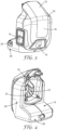
- FIG. 1 is an exploded view of a known exhaust apparatus indicated generally at 10.
- the apparatus 10 is able to connect or otherwise engage to or with a personal protection respiratory device 120, also known as a respirator, either in a permanent fashion or in a releasable manner as will be described in further detail shortly.
- a personal protection respiratory device 120 also known as a respirator
- respirator 120 illustrated in Figures 1 , 2 , 5 , and 7 is indicative of those sold under the trade designation "7500 Series" from 3M Company, St. Paul, MN, of gas, vapor and particulate respirators
- the exhaust apparatus 10 can be utilized with any negative pressure respiratory device 120.
- respirator or "respiratory mask”, as used interchangeably herein, is intended to mean a breathing device worn to prevent the inhalation of hazardous substances, particles, vapors or noxious gases.
- negative pressure respiratory mask is intended to cover any respirator in which the air pressure inside the mask becomes lower than the ambient air pressure when the wearer inhales.
- a negative pressure respiratory mask 120 as described herein is used to mean any form of respirator intended to fit the face of the wearer 100 in a substantially sealed configuration causing the air inhaled and exhaled by the wearer 100 to pass through a filter body or a filter portion of the respirator or exhalation valve).
- Negative pressure respiratory mask 120 can be full or half facepiece mask, depending upon the hazard of concern. Again, these masks utilize a filter which prevents the inhalation of contaminants, particles, gases and vapors from the air inhaled by the wearer.
- Disposable respirators such as those commercially available from 3M Company under the trade designations "8000 Series” and “9000 Series” of cup-shaped and flat-folded products, are lightweight single-piece respirators that employ a filter media which removes particulates and mists from the air stream as the wearer draws a breath. The entire unit is designed to be discarded after some extended period or a single use or single shift, depending on the contaminant.
- Filtering facepieces such as those commercially available from 3M Company under the trade designations "4000 Series”, “6000 Series” and “6500 Series” are generally reusable products and which can have replaceable filter cartridges. Typically one or two cartridges attach securely to half mask or full facepiece which has built into it a corresponding number of valves for inhalation, and usually one for exhalation.
- the personal protection respiratory device 20 that is illustrated in Figure 1 is a half mask to which filters can be attached using bayonet connectors, which is commercially available from 3M Company under trade designation "7500 Series".
- a pair of filter cartridges are attached to the respirator mask 120 at respective inhalation ports 122.
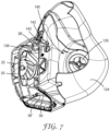
- Each of the inhalation ports 122 has a respective inhalation valve 136 (shown in Figure 7 ) on the inside of the respirator mask 120 which open as a wearer 100 draws a breath.
- the face mask 120 has an exhalation valve 126 with a one-way exhalation valve diaphragm 138 (shown in Figure 7 ) which open as a wearer 100 expels a breath.
- the mask 120 is held in position on the wearer's head by adjustable straps 128 (shown only in Figures 1 and 2 ).
- the respiratory mask 120 has a conformable gasket or seal 124 which generally encloses the wearer's 100 mouth and nose. Since a good seal is needed to ensure filtration of the containments, one drawback in the prior art is that sometimes an uncomfortable build-up of heat and moisture is noticed by the wearer 100 inside the respirator 120. As the wearer 100 works harder, and or wears the respirator 120 for extended periods of time, heat and moisture build-up can occur. The heat and moisture build-up is caused by the trapping of the exhaled breath in the cavity created between the respirator 120 and the wearer's 100 face.
- an exhaust apparatus 10 having a housing 16 with a generally L-shaped form.
- the exhaust apparatus 10 includes an inlet 12 (see Figure 4 ) and an outlet 14 (see Figure 3 ).
- the outlet 14 is formed in a side surface of the housing 16.
- a blower 18 Positioned inside housing 16 between the inlet 12 and the outlet 14 is a blower 18 which in use draws air out of the respiratory device 120.
- the blower 18 has a motor 20 which drives a fan 22.
- the motor 20 is powered by a battery 25, which will be described in further detail shortly with reference to Figure 6 .
- the apparatus 10 has a housing 11 defined by upwardly extending section indicated generally at 24 which houses the inlet 12, outlet 14 and blower 18.
- the housing 11 also has a rearwardly extending section indicated generally at 26 which houses the battery 25 and a controller 28 (shown in Figure 6 ).
- the positioning of the battery 25 (a relatively heavy component of the device 10) in the rearwardly extending section 26 allows the center of mass of the device to sit most closely to the center of mass of the head. This improves the comfort of the apparatus by minimizing the moment of inertia of the device as the user 100 moves his or her head during use.
- a switch mechanism 18 is accessible to the wearer 100.
- the switch mechanism 18 can have a simple on/off mode of operation or can include a variable adjustment so that the wearer 100 can optimize the desired blower speed, and hence, cooling effect based upon the environmental conditions, the task the wearer 100 is undertaking, and the wearer's personal choice.
- the settings may be preconfigured by connection to managing software on a PC via USB connection port 23.
- the connection port 23 also serves as a charging port for the battery 25.
- a cooling effect is achieved by the exhaust apparatus 10 as follows.
- "cooler” ambient air is drawn into the respiratory mask 20 either though the filter cartridges and inlet ports 122 as shown in Figures 1 and 2 in the case of a reusable mask, or through, for example, a filter portion or filtering mask body of the respirator, in the case of a disposable mask.
- Heat and moisture build-up is then caused by trapping the exhaled breath in the cavity created between the respirator 120 and the wearer's 100 face.
- the exhaust apparatus 10 draws this warm and moist air out through the exhaust valve 126 during the exhale breath and reduces the exhalation breathing resistance, as described below. This produces a noticeable cooling benefit for the wearer 100 without placing a respiratory burden on the inhale breath or reducing the life of the filter.
- FIG. 5 shows in greater detail the inlet ports 122 which are defined by port walls 130 which have bayonet fitting 132 of known design.
- the bayonet fittings 132 are provided to connect to filters, such as those series of filters commercially available from 3M Company under the trade designations "2000 Series", “5000 Series” or "6000 Series".
- filters such as those series of filters commercially available from 3M Company under the trade designations "2000 Series", "5000 Series” or "6000 Series".
- filters such as those series of filters commercially available from 3M Company under the trade designations "2000 Series", "5000 Series” or "6000 Series”.
- alternative attachments mechanisms such as the DIN threaded filters may be provided in order to accept differing types of filters.
- an integral cartridge may be provided in line with half mask series, such as those commercially available under the trade designation "4000 Series" from 3M Company.
- the inlet 12 of the exhaust device 10 is shaped to releasably connect by way of an interference fit to the shape and dimensions of the respective exhaust valve 126 situated on the respiratory mask 120. While the exhaust apparatus 10 described herein in relation to Figure 5 connects by way of an interference fit, the skilled person will appreciate that any form of releasable connection to the exhaust valve 126 is possible, including, for example, connection by way of a screw thread, snap fit engagement, bayonet, quick release mechanism etc. The above list is in no way intended to be limiting and exhaustive.
- Figure 9 shows a first embodiment of a respirator 120 in use with an exhaust apparatus 210 according to the present disclosure .
- the exhaust apparatus 210 has a housing 211 (not shown for clarity) similar to that shown in Figures 1 to 7 but reconfigured to house the following features of the disclosure.
- the exhaust apparatus of the present disclosure is intended for use with a negative pressure respiratory mask 120 as described and defined above. That is to say, the term is used to mean any form of respirator intended to fit the face of the wearer 100 in a substantially sealed configuration causing the air inhaled and exhaled by the wearer 100 to pass through a filter body or a filter portion of the respirator or exhalation valve).
- Negative pressure respiratory mask 120 can be full or half facepiece mask, depending upon the hazard of concern. Again, these masks utilize a filter which prevents the inhalation of contaminants, particles, gases and vapors from the air inhaled by the wearer.
- the housing defines an air duct in the form of inlet 212, an air duct in the form of outlet 214, an outlet blower 218 and an inlet blower 219.
- the housing 211 also houses a battery 225 and a controller 228.
- a filter cartridge 270 is attached to the respirator mask 120 at inlet 212.
- An inhalation valve 236 is positioned within inlet 212 on the inside of the respirator mask 120.
- the inhalation valve 136 opens as a wearer 100 draws an inhaled breath.
- An exhalation valve 226 is positioned within the outlet. The exhalation valve 226 opens when a wearer 100 expels an exhaled breath.
- the inhalation valve 236 and exhalation valve 226 are one-way diaphragm valves.
- the respiratory mask 120 has a conformable gasket or seal 224 which generally encloses the wearer's mouth and nose.
- the mask 120 defines a filtered air cavity 240.
- the outlet blower 218 has a motor (not shown for clarity) which drives an outlet fan 222 and which is powered by the battery 225 and is in communication with, and controlled by, the controller 228.
- the inlet blower 219 has a motor which drives an inlet fan 223 and which is powered by the battery 225 and is in communication with, and controlled by, the controller 228.
- the blowers 218, 219 collectively forma blower assembly.
- the wearer's breathing cycle is detected by measuring the pressure of the filtered air volume in the filtered air cavity 240 via a pressure sensor 242 in communication with the controller 228.
- the exhaust apparatus is configured and arranged so that in use the first blower operates throughout the wearer's exhale breath, or a substantial period thereof, and does not operate throughout the wearer's inhale breath, and the second blower operates throughout the wearer's inhale breath, or a substantial period thereof, and does not operate throughout the wearer's exhale breath.
- the controller 228 is able to continuously monitor the pressure in the cavity 240 and control the blowers 218, 219 via the motors in order to ensure that the inlet fan 223 is only operating during the inhale breath of the wearer 100, or a substantial period thereof, and that the outlet fan 222 is only operating during the exhale breath of the wearer 100, or a substantial period thereof. This reduces the inhalatory effort required in order to overcome the pressure drop across the filter as will be described in further detail below.
- FIG 10 shows a second embodiment of a respirator 120 in use with an exhaust apparatus 310 according to the present disclosure which has two filters 370 as opposed to the single filter 170 of the first embodiment as shown in Figure 9 .
- the exhaust apparatus 310 has a housing 311 similar to that shown in Figures 1 to 7 but reconfigured to house the following features of the present disclosure.
- the housing defines an air duct in the form of first and second inlets 312, each of which is associated with a filter 370, an air duct in the form of outlet 314, an outlet blower 318 and an inlet blower 319.
- the housing 311 also houses a battery and a controller (which are not shown for clarity).
- the blowers 318, 319 collectively forma blower assembly.
- the filter cartridges 370 are attached to the respirator mask 120 at inlets 312.
- Inhalation valves 336 are positioned on the inside of the respirator mask 120.
- the inhalation valves 336 open as a wearer 100 draws an inhaled breath.
- An exhalation valve 326 is positioned within the outlet 314.
- the exhalation valve 326 opens when a wearer 100 expels an exhaled breath.
- the inhalation valves 336 and exhalation valve 326 are one-way diaphragm valves.
- the respiratory mask 120 has a conformable gasket or seal 324 which generally encloses the wearer's mouth and nose.
- the mask 120 defines a filtered air cavity 340.
- the outlet blower 318 has a motor (not shown for clarity) which drives an outlet fan 322 and which is powered by the battery and is in communication with, and controlled by, the controller.
- the inlet blower 319 has a motor which drives an inlet fan 323 and which is powered by the battery and is in communication with, and controlled by, the controller.
- the wearer's breathing cycle is detected by measuring the pressure of the filtered air volume in the filtered air cavity 240 via a pressure sensor in communication with the controller.
- the exhaust apparatus is configured and arranged so that in use the first blower operates throughout the wearer's exhale breath, or a substantial period thereof, and does not operate throughout the wearer's inhale breath, and the second blower operates throughout the wearer's inhale breath, or a substantial period thereof, and does not operate throughout the wearer's exhale breath.
- the controller is able to continuously monitor the pressure in the cavity 340 and control the blowers 318, 319 via the motors in order to ensure that the inlet fan 323 is only operating during the inhale breath of the wearer 100 or a substantial period thereof, and that the outlet fan 322 is only operating during the exhale breath of the wearer 100, or a substantial period thereof. This reduces the inhalatory effort required in order to overcome the pressure drop across the filter as will now be described in further detail below.
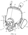
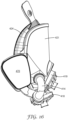
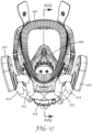
- FIGS 14 to 19 show a third embodiment of a respirator 420 in use with an exhaust apparatus 410 according to the present disclosure
- the exhaust apparatus is for connection to respirators, such as those commercially available from 3M Company under the trade designation "6800 Series", and has two filters 470 arranged on either side of a respirator mask 420.
- the mask 420 has a see-through face mask 421 surrounded by a conformable gasket or seal 424 which generally encloses the wearer's face.
- the mask 420 additionally has a conformable gasket or seal 425 (see Figure 17 ) which encloses the wearer's mouth and nose.
- the mask 420 defines a filtered air cavity 440 within the seal 425.
- the apparatus 410 has an air duct in the form of first and second inlets 412, each of which is associated with a filter 470, an air duct in the form of first and second outlets 414, an outlet blower 418 and an inlet blower 419.
- the apparatus 410 also has a battery and a controller (which are not shown for clarity).
- the blowers 418, 419 collectively form a blower assembly.
- the filter cartridges 470 are attached to the respirator mask 420 at inlets 412.
- An inhalation valve 436 (see Figure18 ) is positioned within the inlet blower 419.
- the inhalation valve 436 opens as a wearer 100 draws an inhaled breath.
- First and second exhalation valves 426 are positioned at the fluidic entrance to the first and second outlets 414 as shown in Figure 18 .
- the exhalation valves 426 open when a wearer 100 expels an exhaled breath.
- the inhalation valve 436 and exhalation valves 426 are one-way diaphragm valves.
- the outlet blower 418 has a motor 430 which drives an outlet fan 422 (see Figure 18 ) and which is powered by the battery and is in communication with, and controlled by, the controller.
- the inlet blower 419 has a motor 431 which drives an inlet fan 423 (again, see Figure 18 ) and which is powered by the battery and is in communication with, and controlled by, the controller.
- the wearer's breathing cycle is detected by measuring the pressure of the filtered air volume in the filtered air cavity 440 via a pressure sensor in communication with the controller.
- the exhaust apparatus is configured and arranged so that in use the first blower operates throughout the wearer's exhale breath, or a substantial period thereof, and does not operate throughout the wearer's inhale breath, and the second blower operates throughout the wearer's inhale breath, or a substantial period thereof, and does not operate throughout the wearer's exhale breath.
- the controller is able to continuously monitor the pressure in the cavity 440 and control the blowers 418, 419 via the motors in order to ensure that the inlet fan 423 is y only operating during the inhale breath of the wearer 100, or a substantial period thereof, and that the outlet fan 422 is only operating during the exhale breath of the wearer 100, or a substantial period thereof. This reduces the inhalatory effort required in order to overcome the pressure drop across the filter as will now be described in further detail below.
- the filters 470 are positioned substantially rearwardly of the face mask 421. This presents the advantage to the user of minimizing the extent to which the filters impair the field of vision.
- This additional volume of air is driven by the additional negative pressure shown in the hatched area 156.
- the additional flow volume through the filter limits filter life.
- the additional negative pressure must be overcome by additional respiratory effort if the same flow rate is to be maintained. This additional respiratory effort may itself cause increased respiratory load resulting in an increased breathing rate.
- the chart shows a representation of pressure in, and flow rate through, the filtered air cavity of the known exhaust apparatus 10 as described in Figures 1 to 7 .
- the dashed line 150 once again represents the flow rate through the mask 120 and the solid line 158 represents the pressure in the mask cavity 140.
- the exhaust apparatus 10 is switched off and to the right it is switched on. With the exhaust apparatus 10 switched off the pressure oscillates about zero subject to the larger maximal negative pressure resulting from the pressure drop across the filters. With the device switched on, the pressure line rises from its low point Z towards zero as the wearer inhales through the filters. As the wearer breaths in through the filter, the controller 28 monitors the rise in pressure in the cavity 140 via the pressure conduit 34.
- the controller 28 controls the motor 20 to initiate the blower 12. This pulls air from the cavity 140 in order to assist the breathing of the wearer.
- the blower 12 continues to operate until such time as the pressure in the cavity 140 falls below the predetermined P 0 at which point the controller stops the motor 20.
- the extent of exhale breath assist may be varied by decreasing the predetermined pressure, as indicated by P D , or increasing the predetermined pressure, as indicated by P I .
- P D delivers a cooler feel to the wearer and P I a warmer feel. It is conceivable that this variation in cooling effect could be controlled by the wearer in response to the operating conditions.
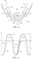
- FIG. 13 the chart shows a representation of pressure in, and flow rate through, the filtered air cavity of the first, second and third embodiments of respirators of the present disclosure.
- the dashed line 150 once again represents the flow rate through the mask 120, 420.
- the solid line 258 represents the pressure in the mask cavity 240, 340, 440.
- To the left of the centerline X-X the exhaust apparatus 210, 310, 410 is switched off and to the right it is switched on. With the exhaust apparatus 210, 310, 410 switched off the pressure oscillates about zero subject to the larger maximal negative pressure resulting from the pressure drop across the filters.
- the controller With the device switched on, the controller detects a negative pressure in the cavity 240, 340, 440 the controller controls the motor to initiate the blower 219, 319, 419. This pulls air through the filters 270, 370, 470 into the cavity 240, 340, 440 in order to assist the inhalation breath of the wearer. As a result the rise in pressure in the cavity 240, 340 increases rapidly as indicated by the pressure line 159 rising rapidly from its low point Z towards zero as the wearer inhales through the filters 270, 370, 470. As the wearer breaths in through the filter, the controller 28 monitors the rise in pressure in the cavity 240, 340, 440.
- the controller When the controller detects a predetermined pressure in the cavity 240, 340, 440 in this instance P 0 (equal to zero), the controller cuts power to the blower 219, 319, 419 and initiates the blower 218, 318, 418. This pulls air from the cavity 140 in order to assist the exhale breath of the wearer. The blower 218, 318, 418 continues to operate until such time as the pressure in the cavity 140 falls below the predetermined P 0 at which point the controller switches power back to the blower 219, 319, 419.
- Line 258' in Figure 13 represents such a situation where the predetermined pressure at which the controller switches power to the blowers 218, 318, 418, 219, 319, 419 in increased to P I .
- This provides the advantage of maintaining a positive pressure within the cavity 240, 340, 440 which serves to minimize the risk of unfiltered air passing into the cavity between the mask and the face of the wearer.
- Figure 13 depicts the same predetermined pressure at the beginning and the end of the exhalation breath, that is to say P 0 , for example, remains constant throughout the exhalation breath
- the first blowers 218, 318, 418 could be started and the second blower 219, 319, 419 could stopped in view of a first predetermined pressure and the first blowers 218, 318, 418 could be stopped started and the second blowers 219, 319, 419 could be started in view of a second predetermined pressure.
Landscapes
- Health & Medical Sciences (AREA)
- General Health & Medical Sciences (AREA)
- Pulmonology (AREA)
- Life Sciences & Earth Sciences (AREA)
- Anesthesiology (AREA)
- Biomedical Technology (AREA)
- Heart & Thoracic Surgery (AREA)
- Hematology (AREA)
- Engineering & Computer Science (AREA)
- Animal Behavior & Ethology (AREA)
- Emergency Medicine (AREA)
- Public Health (AREA)
- Veterinary Medicine (AREA)
- Business, Economics & Management (AREA)
- Emergency Management (AREA)
- Respiratory Apparatuses And Protective Means (AREA)
Claims (10)
- Eine persönliche Atemschutzvorrichtung (120; 420), die ein gefiltertes Luftvolumen in einem gefilterten Lufthohlraum (240; 340; 440) neben dem Gesicht eines Trägers (100) definiert und mindestens ein Ausatmungsventil (226; 326; 426) und mindestens ein Einatmungsventil (236; 336; 436) aufweist, wobei die Einatmungs- und Ausatmungsventile Einweg-Membranventile sind; wobei die persönliche Atemschutzvorrichtung ferner eine angetriebene Einrichtung (210; 310; 410) aufweist, die entweder dauerhaft oder lösbar damit verbunden ist,
wobei die angetriebene Einrichtung Folgendes aufweist:einen ersten Luftkanal (214; 314; 414) in Fluidverbindung mit dem mindestens einen Ausatmungsventil,einen zweiten Luftkanal (212; 312; 412) in Fluidverbindung mit dem mindestens einen Einatmungsventil,ein erstes Gebläse (218; 318; 418), das dem ersten Luftkanal zugeordnet ist, undein zweites Gebläse (219; 319; 419), das dem zweiten Luftkanal zugeordnet ist,wobei das erste und das zweite Gebläse (218, 219; 318, 319; 418, 419) dazu dienen, Luft selektiv durch den ersten bzw. zweiten Kanal zu leiten und auf den Atemzyklus des Trägers zu reagieren, so dass bei Verwendung,das erste Gebläse einen wesentlichen Teil der vom Träger ausgeatmeten Luft durch das mindestens eine Ausatmungsventil und durch den ersten Kanal nach außen saugt, unddas zweite Gebläse einen wesentlichen Teil der vom Träger eingeatmeten Luft durch den zweiten Kanal und durch das mindestens eine Einatmungsventil nach innen saugt;wobeidas erste Gebläse während der gesamten Ausatmungszeit des Trägers oder über einen wesentlichen Zeitraum davon in Betrieb ist, und während der Einatmungszeit des Trägers nicht in Betrieb ist, unddas zweite Gebläse während der gesamten Einatmungszeit des Trägers oder über einen wesentlichen Zeitraum davon in Betrieb ist, und während der Ausatmungszeit des Trägers nicht in Betrieb ist; undwobei die Abführungseinrichtung ferner aufweist:eine Steuerung (228),einen Drucksensor (242) zum Erfassen eines Parameters, der mittels des Atemzyklus des Trägers erzeugt wird, und Senden eines Signals, das den Parameter der Steuerung angibt,wobei die Steuerung mit dem Sensor und dem ersten und zweiten Gebläse in Verbindung steht,wobei die Steuerung das erste und das zweite Gebläse als Reaktion auf das Signal betreibt, undwobei der Parameter Druck ist, das Signal ein Drucksignal ist und der erfasste Druck der Druck des gefilterten Luftvolumens in dem gefilterten Lufthohlraum der persönlichen Atemschutzvorrichtung ist. - Die persönliche Atemschutzvorrichtung (120; 420) nach Anspruch 1, wobei die Steuerung (228) das erste Gebläse (218; 318; 418) startet und das zweite Gebläse (219; 319; 419) stoppt, wenn der vom Drucksensor (242) erfasste Druck einen ersten vorbestimmten Druck erreicht oder die Druckänderungsrate eine erste vorbestimmte Rate erreicht.
- Die persönliche Atemschutzvorrichtung (120; 420) nach Anspruch 1 oder 2, wobei die Steuerung das erste Gebläse (218; 318; 418) stoppt und das zweite Gebläse (219; 319; 419) startet, wenn der von dem Drucksensor (242) erfasste Druck unter einen zweiten vorbestimmten Druck fällt oder die Druckänderungsrate eine zweite vorbestimmte Rate erreicht.
- Die persönliche Atemschutzvorrichtung (120; 420) nach Anspruch 2 und 3, wobei der erste vorbestimmte Druck und der zweite vorbestimmte Druck ein gemeinsamer vorbestimmter Druck sind.
- Die persönliche Atemschutzvorrichtung (120; 420) nach Anspruch 4, wobei der gemeinsame vorbestimmte Druck im Wesentlichen ein Umgebungsdruck ist, so dass die Steuerung das erste Gebläse (218; 318; 418) startet und das zweite Gebläse im Wesentlichen zu Beginn des Ausatmens des Trägers stoppt und das erste Gebläse stoppt und das zweite Gebläse im Wesentlichen am Ende des Ausatmens des Trägers startet.
- Die persönliche Atemschutzvorrichtung (120; 420) nach Anspruch 4, wobei der gemeinsame vorbestimmte Druck niedriger ist als der Umgebungsdruck, so dass die Steuerung das erste Gebläse (218; 318; 418) startet und das zweite Gebläse (219; 319; 419) kurz vor dem Beginn des Ausatmens des Trägers stoppt und das erste Gebläse stoppt und das zweite Gebläse kurz nach dem Ende des Ausatmens des Trägers startet.
- Die persönliche Atemschutzvorrichtung (120; 420) nach Anspruch 2 und 3, wobei der zweite vorbestimmte Druck höher ist als der erste vorbestimmte Druck, so dass die Steuerung das erste Gebläse (218; 318; 418) startet und das zweite Gebläse (219; 319; 419) kurz vor dem Beginn des Ausatmens des Trägers stoppt und das erste Gebläse stoppt und das zweite Gebläse kurz vor dem Ende des Ausatmens des Trägers startet.
- Die persönliche Atemschutzvorrichtung (120; 420) nach Anspruch 1, wobei das erste und das zweite Gebläse (218, 219; 318, 319; 418, 419) ferner einen Einlass, einen Motor (430, 431), einen Ventilator (222, 223; 322, 323; 422, 423) und einen Auslass aufweisen.
- Die persönliche Atemschutzvorrichtung nach Anspruch 1, wobei die persönliche Atemschutzvorrichtung aus einer Gruppe ausgewählt ist, die aus Einweg-, wiederverwendbaren, Halbmasken-, Vollflächen-, Partikel-, Gas- und Dampf- und eng anliegenden Atemschutzhauben besteht.
- Die persönliche Atemschutzvorrichtung nach Anspruch 1, wobei die persönliche Atemschutzvorrichtung ein Unterdruckatemschutzgerät ist.
Applications Claiming Priority (2)
| Application Number | Priority Date | Filing Date | Title |
|---|---|---|---|
| GBGB1700576.0A GB201700576D0 (en) | 2017-01-12 | 2017-01-12 | Powered apparatus for a personal protection respiratory device |
| PCT/US2018/013340 WO2018132587A1 (en) | 2017-01-12 | 2018-01-11 | Powered apparatus for a personal protection respiratory device |
Publications (2)
| Publication Number | Publication Date |
|---|---|
| EP3568211A1 EP3568211A1 (de) | 2019-11-20 |
| EP3568211B1 true EP3568211B1 (de) | 2025-06-25 |
Family
ID=58463472
Family Applications (1)
| Application Number | Title | Priority Date | Filing Date |
|---|---|---|---|
| EP18703109.1A Active EP3568211B1 (de) | 2017-01-12 | 2018-01-11 | Stromgetriebene vorrichtung für eine persönliche atemschutzvorrichtung |
Country Status (4)
| Country | Link |
|---|---|
| US (1) | US11554233B2 (de) |
| EP (1) | EP3568211B1 (de) |
| GB (1) | GB201700576D0 (de) |
| WO (1) | WO2018132587A1 (de) |
Families Citing this family (24)
| Publication number | Priority date | Publication date | Assignee | Title |
|---|---|---|---|---|
| CN109125971A (zh) * | 2017-06-16 | 2019-01-04 | 北京慧海达科技有限公司 | 一种自主调压控温的太阳能动力防霾助吸器 |
| KR102293918B1 (ko) * | 2019-06-14 | 2021-08-26 | 엘지전자 주식회사 | 마스크 장치 및 그 제어 방법 |
| TWI683631B (zh) * | 2019-06-18 | 2020-02-01 | 林明賢 | 氫氧氣呼吸罩 |
| KR102293924B1 (ko) * | 2019-06-19 | 2021-08-26 | 엘지전자 주식회사 | 마스크 장치 및 그 제어 방법 |
| CN211354013U (zh) * | 2020-04-27 | 2020-08-28 | 林伟丰 | 一种多功能隔离防护面罩 |
| IT202000009337A1 (it) * | 2020-04-29 | 2021-10-29 | Milano Politecnico | Dispositivo di ventilazione per mascherine filtranti e relativo metodo di controllo e sistema di ventilazione comprendente tale dispositivo |
| KR102494579B1 (ko) * | 2020-06-05 | 2023-02-02 | 엘지전자 주식회사 | 마스크 장치 |
| KR102408364B1 (ko) | 2020-06-05 | 2022-06-13 | 엘지전자 주식회사 | 마스크 장치 |
| KR102256713B1 (ko) * | 2020-06-05 | 2021-05-27 | 엘지전자 주식회사 | 마스크 장치 및 그 제어방법 |
| KR102452392B1 (ko) | 2020-06-05 | 2022-10-11 | 엘지전자 주식회사 | 마스크 장치 |
| KR102309925B1 (ko) | 2020-06-05 | 2021-10-08 | 엘지전자 주식회사 | 마스크 장치 |
| KR102307772B1 (ko) * | 2020-06-05 | 2021-10-05 | 엘지전자 주식회사 | 마스크 장치 |
| KR102367071B1 (ko) | 2020-06-05 | 2022-02-25 | 엘지전자 주식회사 | 마스크 장치 |
| KR102418745B1 (ko) | 2020-06-30 | 2022-07-11 | 엘지전자 주식회사 | 마스크 장치 |
| KR102436838B1 (ko) | 2020-06-30 | 2022-08-26 | 엘지전자 주식회사 | 마스크 장치 및 그 제어방법 |
| KR102460798B1 (ko) | 2020-06-30 | 2022-10-31 | 엘지전자 주식회사 | 마스크 장치 |
| CN111714802B (zh) * | 2020-07-16 | 2025-04-04 | 深圳市森木光电科技有限公司 | 可多风路切换的呼吸器 |
| KR102458618B1 (ko) | 2020-07-17 | 2022-10-25 | 엘지전자 주식회사 | 마스크 장치 및 그 제어방법 |
| KR102294479B1 (ko) | 2020-08-28 | 2021-08-27 | 엘지전자 주식회사 | 살균 케이스 |
| US12172040B2 (en) | 2020-09-15 | 2024-12-24 | Emad Eskandar | Wearable, maskless respiratory isolation device |
| TWI751894B (zh) * | 2021-01-21 | 2022-01-01 | 陳勇仁 | 空氣清淨機及其濾組 |
| CN113521474B (zh) * | 2021-07-12 | 2024-06-25 | 济南国科医工科技发展有限公司 | 可控压力呼吸面罩装置 |
| US20250152978A1 (en) * | 2022-02-04 | 2025-05-15 | William Maxwell | A mask configured for pressure maintenance |
| US12415096B2 (en) * | 2024-01-04 | 2025-09-16 | Changzhou Shine Science & Technology Co.Ltd. | Adaptive auxiliary air supply respirator and control method thereof |
Family Cites Families (16)
| Publication number | Priority date | Publication date | Assignee | Title |
|---|---|---|---|---|
| DE8207236U1 (de) * | 1982-03-15 | 1982-07-22 | BHS-Bayerische Berg-, Hütten- und Salzwerke AG, 8000 München | Vorrichtung zum absaugen der von materialbahnen abgeschnittenen randstreifen, insbesondere von durch laengsschneide- und rillmaschinen abgeschnittenen randstreifen einer wellpappenbahn |
| US4549542A (en) | 1983-07-25 | 1985-10-29 | Chien Chao Huei | Multiple-effect respirator |
| US4646732A (en) * | 1985-08-26 | 1987-03-03 | Chien Chao Huei | Circulative respiratory mask |
| US5372130A (en) * | 1992-02-26 | 1994-12-13 | Djs&T Limited Partnership | Face mask assembly and method having a fan and replaceable filter |
| EP3064242A1 (de) * | 2003-04-28 | 2016-09-07 | Advanced Circulatory Systems Inc. | Lüfter und verfahren zur behandlung von kopftrauma und geringer blutzirkulation |
| TWI282288B (en) | 2003-08-20 | 2007-06-11 | Jun-Shin Chang | Medical mask with supply of hot air for treating respiratory tract diseases like SARS |
| US8584676B2 (en) * | 2003-11-19 | 2013-11-19 | Immediate Response Technologies | Breath responsive filter blower respirator system |
| JP2006102324A (ja) * | 2004-10-07 | 2006-04-20 | Shigematsu Works Co Ltd | 電動ファン付呼吸用保護具 |
| JP5041596B2 (ja) * | 2007-12-07 | 2012-10-03 | 株式会社重松製作所 | 呼吸装置 |
| EP2486959B1 (de) * | 2009-10-07 | 2016-09-28 | Shigematsu Works Co., Ltd. | Atmungsunterstützungsvorrichtung |
| CN202236942U (zh) | 2011-10-13 | 2012-05-30 | 吴琼 | 一种矿用可循环换风防尘装置 |
| JP5592908B2 (ja) * | 2012-02-23 | 2014-09-17 | 興研株式会社 | 呼吸用保護具 |
| GB2508184A (en) | 2012-11-22 | 2014-05-28 | 3M Innovative Properties Co | Powered exhaust apparatus for respiratory device |
| US20140261425A1 (en) * | 2013-03-13 | 2014-09-18 | Robert A. Connor | Wearable Positive Airway Pressure (PAP) with Primary and Bolus Airflow |
| CN204655706U (zh) | 2015-02-15 | 2015-09-23 | 苏州鱼跃医疗科技有限公司 | 基于鼓风机的呼吸系统 |
| GB201511904D0 (en) | 2015-07-07 | 2015-08-19 | 3M Innovative Properties Co | Powered exhaust apparatus for a personal protection respiratory device |
-
2017
- 2017-01-12 GB GBGB1700576.0A patent/GB201700576D0/en not_active Ceased
-
2018
- 2018-01-11 WO PCT/US2018/013340 patent/WO2018132587A1/en not_active Ceased
- 2018-01-11 US US16/476,327 patent/US11554233B2/en active Active
- 2018-01-11 EP EP18703109.1A patent/EP3568211B1/de active Active
Also Published As
| Publication number | Publication date |
|---|---|
| US11554233B2 (en) | 2023-01-17 |
| US20200038614A1 (en) | 2020-02-06 |
| EP3568211A1 (de) | 2019-11-20 |
| WO2018132587A1 (en) | 2018-07-19 |
| GB201700576D0 (en) | 2017-03-01 |
Similar Documents
| Publication | Publication Date | Title |
|---|---|---|
| EP3568211B1 (de) | Stromgetriebene vorrichtung für eine persönliche atemschutzvorrichtung | |
| US12138491B2 (en) | Powered exhaust apparatus for a personal protection respiratory device | |
| US20220370837A1 (en) | Powered exhaust apparatus for a personal protection respiratory device | |
| KR102137781B1 (ko) | 개인용 호흡 보호 기구를 위한 동력식 배기 장치 | |
| US4590951A (en) | Breathing apparatus | |
| JP2018531633A (ja) | 個人保護呼吸器具用の電動排気装置 | |
| EP3797837A1 (de) | Stromgetriebene abgasvorrichtung für eine personalisierte atemschutzvorrichtung |
Legal Events
| Date | Code | Title | Description |
|---|---|---|---|
| STAA | Information on the status of an ep patent application or granted ep patent |
Free format text: STATUS: UNKNOWN |
|
| STAA | Information on the status of an ep patent application or granted ep patent |
Free format text: STATUS: THE INTERNATIONAL PUBLICATION HAS BEEN MADE |
|
| PUAI | Public reference made under article 153(3) epc to a published international application that has entered the european phase |
Free format text: ORIGINAL CODE: 0009012 |
|
| STAA | Information on the status of an ep patent application or granted ep patent |
Free format text: STATUS: REQUEST FOR EXAMINATION WAS MADE |
|
| 17P | Request for examination filed |
Effective date: 20190717 |
|
| AK | Designated contracting states |
Kind code of ref document: A1 Designated state(s): AL AT BE BG CH CY CZ DE DK EE ES FI FR GB GR HR HU IE IS IT LI LT LU LV MC MK MT NL NO PL PT RO RS SE SI SK SM TR |
|
| AX | Request for extension of the european patent |
Extension state: BA ME |
|
| DAV | Request for validation of the european patent (deleted) | ||
| DAX | Request for extension of the european patent (deleted) | ||
| STAA | Information on the status of an ep patent application or granted ep patent |
Free format text: STATUS: EXAMINATION IS IN PROGRESS |
|
| 17Q | First examination report despatched |
Effective date: 20230630 |
|
| GRAP | Despatch of communication of intention to grant a patent |
Free format text: ORIGINAL CODE: EPIDOSNIGR1 |
|
| STAA | Information on the status of an ep patent application or granted ep patent |
Free format text: STATUS: GRANT OF PATENT IS INTENDED |
|
| INTG | Intention to grant announced |
Effective date: 20250121 |
|
| RIC1 | Information provided on ipc code assigned before grant |
Ipc: A61M 16/06 20060101ALI20250113BHEP Ipc: A61M 16/00 20060101ALI20250113BHEP Ipc: A62B 18/00 20060101AFI20250113BHEP |
|
| P01 | Opt-out of the competence of the unified patent court (upc) registered |
Free format text: CASE NUMBER: APP_6750/2025 Effective date: 20250210 |
|
| GRAS | Grant fee paid |
Free format text: ORIGINAL CODE: EPIDOSNIGR3 |
|
| GRAA | (expected) grant |
Free format text: ORIGINAL CODE: 0009210 |
|
| STAA | Information on the status of an ep patent application or granted ep patent |
Free format text: STATUS: THE PATENT HAS BEEN GRANTED |
|
| AK | Designated contracting states |
Kind code of ref document: B1 Designated state(s): AL AT BE BG CH CY CZ DE DK EE ES FI FR GB GR HR HU IE IS IT LI LT LU LV MC MK MT NL NO PL PT RO RS SE SI SK SM TR |
|
| REG | Reference to a national code |
Ref country code: GB Ref legal event code: FG4D |
|
| REG | Reference to a national code |
Ref country code: CH Ref legal event code: EP |
|
| REG | Reference to a national code |
Ref country code: DE Ref legal event code: R096 Ref document number: 602018082871 Country of ref document: DE |
|
| REG | Reference to a national code |
Ref country code: CH Ref legal event code: EP |
|
| REG | Reference to a national code |
Ref country code: IE Ref legal event code: FG4D |
|
| PG25 | Lapsed in a contracting state [announced via postgrant information from national office to epo] |
Ref country code: FI Free format text: LAPSE BECAUSE OF FAILURE TO SUBMIT A TRANSLATION OF THE DESCRIPTION OR TO PAY THE FEE WITHIN THE PRESCRIBED TIME-LIMIT Effective date: 20250625 |
|
| REG | Reference to a national code |
Ref country code: LT Ref legal event code: MG9D |
|
| PG25 | Lapsed in a contracting state [announced via postgrant information from national office to epo] |
Ref country code: GR Free format text: LAPSE BECAUSE OF FAILURE TO SUBMIT A TRANSLATION OF THE DESCRIPTION OR TO PAY THE FEE WITHIN THE PRESCRIBED TIME-LIMIT Effective date: 20250926 Ref country code: NO Free format text: LAPSE BECAUSE OF FAILURE TO SUBMIT A TRANSLATION OF THE DESCRIPTION OR TO PAY THE FEE WITHIN THE PRESCRIBED TIME-LIMIT Effective date: 20250925 |
|
| PG25 | Lapsed in a contracting state [announced via postgrant information from national office to epo] |
Ref country code: BG Free format text: LAPSE BECAUSE OF FAILURE TO SUBMIT A TRANSLATION OF THE DESCRIPTION OR TO PAY THE FEE WITHIN THE PRESCRIBED TIME-LIMIT Effective date: 20250625 |
|
| PG25 | Lapsed in a contracting state [announced via postgrant information from national office to epo] |
Ref country code: HR Free format text: LAPSE BECAUSE OF FAILURE TO SUBMIT A TRANSLATION OF THE DESCRIPTION OR TO PAY THE FEE WITHIN THE PRESCRIBED TIME-LIMIT Effective date: 20250625 |
|
| PG25 | Lapsed in a contracting state [announced via postgrant information from national office to epo] |
Ref country code: RS Free format text: LAPSE BECAUSE OF FAILURE TO SUBMIT A TRANSLATION OF THE DESCRIPTION OR TO PAY THE FEE WITHIN THE PRESCRIBED TIME-LIMIT Effective date: 20250925 |
|
| PG25 | Lapsed in a contracting state [announced via postgrant information from national office to epo] |
Ref country code: LV Free format text: LAPSE BECAUSE OF FAILURE TO SUBMIT A TRANSLATION OF THE DESCRIPTION OR TO PAY THE FEE WITHIN THE PRESCRIBED TIME-LIMIT Effective date: 20250625 |
|
| REG | Reference to a national code |
Ref country code: NL Ref legal event code: MP Effective date: 20250625 |
|
| PG25 | Lapsed in a contracting state [announced via postgrant information from national office to epo] |
Ref country code: NL Free format text: LAPSE BECAUSE OF FAILURE TO SUBMIT A TRANSLATION OF THE DESCRIPTION OR TO PAY THE FEE WITHIN THE PRESCRIBED TIME-LIMIT Effective date: 20250625 |
|
| PG25 | Lapsed in a contracting state [announced via postgrant information from national office to epo] |
Ref country code: PT Free format text: LAPSE BECAUSE OF FAILURE TO SUBMIT A TRANSLATION OF THE DESCRIPTION OR TO PAY THE FEE WITHIN THE PRESCRIBED TIME-LIMIT Effective date: 20251027 |
|
| REG | Reference to a national code |
Ref country code: AT Ref legal event code: MK05 Ref document number: 1805877 Country of ref document: AT Kind code of ref document: T Effective date: 20250625 |
|
| PG25 | Lapsed in a contracting state [announced via postgrant information from national office to epo] |
Ref country code: IS Free format text: LAPSE BECAUSE OF FAILURE TO SUBMIT A TRANSLATION OF THE DESCRIPTION OR TO PAY THE FEE WITHIN THE PRESCRIBED TIME-LIMIT Effective date: 20251025 |
|
| PGFP | Annual fee paid to national office [announced via postgrant information from national office to epo] |
Ref country code: GB Payment date: 20251219 Year of fee payment: 9 |
|
| PG25 | Lapsed in a contracting state [announced via postgrant information from national office to epo] |
Ref country code: SM Free format text: LAPSE BECAUSE OF FAILURE TO SUBMIT A TRANSLATION OF THE DESCRIPTION OR TO PAY THE FEE WITHIN THE PRESCRIBED TIME-LIMIT Effective date: 20250625 Ref country code: AT Free format text: LAPSE BECAUSE OF FAILURE TO SUBMIT A TRANSLATION OF THE DESCRIPTION OR TO PAY THE FEE WITHIN THE PRESCRIBED TIME-LIMIT Effective date: 20250625 |
|
| PG25 | Lapsed in a contracting state [announced via postgrant information from national office to epo] |
Ref country code: CZ Free format text: LAPSE BECAUSE OF FAILURE TO SUBMIT A TRANSLATION OF THE DESCRIPTION OR TO PAY THE FEE WITHIN THE PRESCRIBED TIME-LIMIT Effective date: 20250625 |
|
| PG25 | Lapsed in a contracting state [announced via postgrant information from national office to epo] |
Ref country code: PL Free format text: LAPSE BECAUSE OF FAILURE TO SUBMIT A TRANSLATION OF THE DESCRIPTION OR TO PAY THE FEE WITHIN THE PRESCRIBED TIME-LIMIT Effective date: 20250625 |
|
| PG25 | Lapsed in a contracting state [announced via postgrant information from national office to epo] |
Ref country code: EE Free format text: LAPSE BECAUSE OF FAILURE TO SUBMIT A TRANSLATION OF THE DESCRIPTION OR TO PAY THE FEE WITHIN THE PRESCRIBED TIME-LIMIT Effective date: 20250625 |
|
| PG25 | Lapsed in a contracting state [announced via postgrant information from national office to epo] |
Ref country code: SK Free format text: LAPSE BECAUSE OF FAILURE TO SUBMIT A TRANSLATION OF THE DESCRIPTION OR TO PAY THE FEE WITHIN THE PRESCRIBED TIME-LIMIT Effective date: 20250625 |
|
| PG25 | Lapsed in a contracting state [announced via postgrant information from national office to epo] |
Ref country code: ES Free format text: LAPSE BECAUSE OF FAILURE TO SUBMIT A TRANSLATION OF THE DESCRIPTION OR TO PAY THE FEE WITHIN THE PRESCRIBED TIME-LIMIT Effective date: 20250625 |
|
| PG25 | Lapsed in a contracting state [announced via postgrant information from national office to epo] |
Ref country code: DK Free format text: LAPSE BECAUSE OF FAILURE TO SUBMIT A TRANSLATION OF THE DESCRIPTION OR TO PAY THE FEE WITHIN THE PRESCRIBED TIME-LIMIT Effective date: 20250625 |
|
| PGFP | Annual fee paid to national office [announced via postgrant information from national office to epo] |
Ref country code: DE Payment date: 20251217 Year of fee payment: 9 |
|
| PG25 | Lapsed in a contracting state [announced via postgrant information from national office to epo] |
Ref country code: IT Free format text: LAPSE BECAUSE OF FAILURE TO SUBMIT A TRANSLATION OF THE DESCRIPTION OR TO PAY THE FEE WITHIN THE PRESCRIBED TIME-LIMIT Effective date: 20250625 |
|
| PLBE | No opposition filed within time limit |
Free format text: ORIGINAL CODE: 0009261 |
|
| STAA | Information on the status of an ep patent application or granted ep patent |
Free format text: STATUS: NO OPPOSITION FILED WITHIN TIME LIMIT |