EP3567792A1 - Procédé et dispositif pour faire fonctionner un dispositif de type machine dans un système de communication sans fil - Google Patents
Procédé et dispositif pour faire fonctionner un dispositif de type machine dans un système de communication sans fil Download PDFInfo
- Publication number
- EP3567792A1 EP3567792A1 EP19184102.2A EP19184102A EP3567792A1 EP 3567792 A1 EP3567792 A1 EP 3567792A1 EP 19184102 A EP19184102 A EP 19184102A EP 3567792 A1 EP3567792 A1 EP 3567792A1
- Authority
- EP
- European Patent Office
- Prior art keywords
- iot
- information
- reference signal
- terminal
- lte
- Prior art date
- Legal status (The legal status is an assumption and is not a legal conclusion. Google has not performed a legal analysis and makes no representation as to the accuracy of the status listed.)
- Granted
Links
- 238000000034 method Methods 0.000 title claims abstract description 79
- 238000004891 communication Methods 0.000 title claims abstract description 74
- 101150071746 Pbsn gene Proteins 0.000 claims description 22
- 230000005540 biological transmission Effects 0.000 description 88
- 238000010586 diagram Methods 0.000 description 38
- 230000008569 process Effects 0.000 description 17
- 230000008054 signal transmission Effects 0.000 description 14
- 239000013256 coordination polymer Substances 0.000 description 13
- 238000005516 engineering process Methods 0.000 description 13
- 238000010295 mobile communication Methods 0.000 description 8
- 230000006870 function Effects 0.000 description 7
- 201000003042 peeling skin syndrome Diseases 0.000 description 7
- 229920001467 poly(styrenesulfonates) Polymers 0.000 description 7
- 230000011664 signaling Effects 0.000 description 7
- 238000001514 detection method Methods 0.000 description 6
- 238000012545 processing Methods 0.000 description 6
- 101150096310 SIB1 gene Proteins 0.000 description 5
- 230000001413 cellular effect Effects 0.000 description 5
- 238000003860 storage Methods 0.000 description 5
- 239000000969 carrier Substances 0.000 description 4
- 238000004590 computer program Methods 0.000 description 4
- 238000013507 mapping Methods 0.000 description 4
- 238000005259 measurement Methods 0.000 description 4
- 239000000470 constituent Substances 0.000 description 3
- 241000700159 Rattus Species 0.000 description 2
- 238000013461 design Methods 0.000 description 2
- 238000011161 development Methods 0.000 description 2
- 238000009313 farming Methods 0.000 description 2
- 238000013468 resource allocation Methods 0.000 description 2
- 241000282412 Homo Species 0.000 description 1
- 206010042135 Stomatitis necrotising Diseases 0.000 description 1
- 230000004913 activation Effects 0.000 description 1
- 238000003491 array Methods 0.000 description 1
- 230000008859 change Effects 0.000 description 1
- 238000010276 construction Methods 0.000 description 1
- 230000000694 effects Effects 0.000 description 1
- 230000036541 health Effects 0.000 description 1
- 230000006872 improvement Effects 0.000 description 1
- 238000012423 maintenance Methods 0.000 description 1
- 238000004519 manufacturing process Methods 0.000 description 1
- 201000008585 noma Diseases 0.000 description 1
- 230000008439 repair process Effects 0.000 description 1
- 238000001228 spectrum Methods 0.000 description 1
- 230000007480 spreading Effects 0.000 description 1
- 238000003892 spreading Methods 0.000 description 1
- 238000012546 transfer Methods 0.000 description 1
- XLYOFNOQVPJJNP-UHFFFAOYSA-N water Substances O XLYOFNOQVPJJNP-UHFFFAOYSA-N 0.000 description 1
Images


Classifications
-
- H—ELECTRICITY
- H04—ELECTRIC COMMUNICATION TECHNIQUE
- H04J—MULTIPLEX COMMUNICATION
- H04J11/00—Orthogonal multiplex systems, e.g. using WALSH codes
- H04J11/0069—Cell search, i.e. determining cell identity [cell-ID]
- H04J11/0079—Acquisition of downlink reference signals, e.g. detection of cell-ID
-
- H—ELECTRICITY
- H04—ELECTRIC COMMUNICATION TECHNIQUE
- H04L—TRANSMISSION OF DIGITAL INFORMATION, e.g. TELEGRAPHIC COMMUNICATION
- H04L5/00—Arrangements affording multiple use of the transmission path
- H04L5/003—Arrangements for allocating sub-channels of the transmission path
- H04L5/0048—Allocation of pilot signals, i.e. of signals known to the receiver
- H04L5/005—Allocation of pilot signals, i.e. of signals known to the receiver of common pilots, i.e. pilots destined for multiple users or terminals
-
- H—ELECTRICITY
- H04—ELECTRIC COMMUNICATION TECHNIQUE
- H04J—MULTIPLEX COMMUNICATION
- H04J11/00—Orthogonal multiplex systems, e.g. using WALSH codes
- H04J11/0069—Cell search, i.e. determining cell identity [cell-ID]
- H04J11/0073—Acquisition of primary synchronisation channel, e.g. detection of cell-ID within cell-ID group
-
- H—ELECTRICITY
- H04—ELECTRIC COMMUNICATION TECHNIQUE
- H04J—MULTIPLEX COMMUNICATION
- H04J11/00—Orthogonal multiplex systems, e.g. using WALSH codes
- H04J11/0069—Cell search, i.e. determining cell identity [cell-ID]
- H04J11/0076—Acquisition of secondary synchronisation channel, e.g. detection of cell-ID group
-
- H—ELECTRICITY
- H04—ELECTRIC COMMUNICATION TECHNIQUE
- H04L—TRANSMISSION OF DIGITAL INFORMATION, e.g. TELEGRAPHIC COMMUNICATION
- H04L27/00—Modulated-carrier systems
- H04L27/26—Systems using multi-frequency codes
-
- H—ELECTRICITY
- H04—ELECTRIC COMMUNICATION TECHNIQUE
- H04L—TRANSMISSION OF DIGITAL INFORMATION, e.g. TELEGRAPHIC COMMUNICATION
- H04L5/00—Arrangements affording multiple use of the transmission path
- H04L5/003—Arrangements for allocating sub-channels of the transmission path
- H04L5/0053—Allocation of signaling, i.e. of overhead other than pilot signals
-
- H—ELECTRICITY
- H04—ELECTRIC COMMUNICATION TECHNIQUE
- H04L—TRANSMISSION OF DIGITAL INFORMATION, e.g. TELEGRAPHIC COMMUNICATION
- H04L5/00—Arrangements affording multiple use of the transmission path
- H04L5/003—Arrangements for allocating sub-channels of the transmission path
- H04L5/0058—Allocation criteria
- H04L5/0064—Rate requirement of the data, e.g. scalable bandwidth, data priority
-
- H—ELECTRICITY
- H04—ELECTRIC COMMUNICATION TECHNIQUE
- H04L—TRANSMISSION OF DIGITAL INFORMATION, e.g. TELEGRAPHIC COMMUNICATION
- H04L5/00—Arrangements affording multiple use of the transmission path
- H04L5/0091—Signaling for the administration of the divided path
- H04L5/0092—Indication of how the channel is divided
-
- H—ELECTRICITY
- H04—ELECTRIC COMMUNICATION TECHNIQUE
- H04W—WIRELESS COMMUNICATION NETWORKS
- H04W4/00—Services specially adapted for wireless communication networks; Facilities therefor
- H04W4/70—Services for machine-to-machine communication [M2M] or machine type communication [MTC]
-
- H—ELECTRICITY
- H04—ELECTRIC COMMUNICATION TECHNIQUE
- H04W—WIRELESS COMMUNICATION NETWORKS
- H04W52/00—Power management, e.g. TPC [Transmission Power Control], power saving or power classes
- H04W52/04—TPC
- H04W52/30—TPC using constraints in the total amount of available transmission power
- H04W52/32—TPC of broadcast or control channels
- H04W52/325—Power control of control or pilot channels
-
- H—ELECTRICITY
- H04—ELECTRIC COMMUNICATION TECHNIQUE
- H04J—MULTIPLEX COMMUNICATION
- H04J2211/00—Orthogonal indexing scheme relating to orthogonal multiplex systems
- H04J2211/003—Orthogonal indexing scheme relating to orthogonal multiplex systems within particular systems or standards
- H04J2211/005—Long term evolution [LTE]
-
- H—ELECTRICITY
- H04—ELECTRIC COMMUNICATION TECHNIQUE
- H04L—TRANSMISSION OF DIGITAL INFORMATION, e.g. TELEGRAPHIC COMMUNICATION
- H04L5/00—Arrangements affording multiple use of the transmission path
- H04L5/003—Arrangements for allocating sub-channels of the transmission path
- H04L5/0037—Inter-user or inter-terminal allocation
Definitions
- the present disclosure relates to a method and a device for operating a machine type device in a wireless communication system, and more particularly, to a method and a device that enable a machine type device to perform communication using signal transmission/reception information of an existing communication system.
- the 5G or pre-5G communication system is also called a 'Beyond 4G Network' or a 'Post LTE System'.
- the 5G communication system is considered to be implemented in higher frequency (mmWave) bands, e.g., 60GHz bands, so as to accomplish higher data rates.
- mmWave e.g., 60GHz bands
- MIMO massive multiple-input multiple-output
- FD-MIMO Full Dimensional MIMO
- array antenna an analog beam forming, large scale antenna techniques are discussed in 5G communication systems.
- RANs Cloud Radio Access Networks
- D2D device-to-device
- CoMP Coordinated Multi-Points
- FQAM Hybrid FSK and QAM Modulation
- SWSC sliding window superposition coding
- ACM advanced coding modulation
- FBMC filter bank multi carrier
- NOMA non-orthogonal multiple access
- SCMA sparse code multiple access
- the Internet which is a human centered connectivity network where humans generate and consume information
- IoT Internet of Things
- IoE Internet of Everything
- sensing technology “wired/wireless communication and network infrastructure”, “service interface technology”, and “Security technology”
- M2M Machine-to-Machine
- MTC Machine Type Communication
- IoT Internet technology services
- IoT may be applied to a variety of fields including smart home, smart building, smart city, smart car or connected cars, smart grid, health care, smart appliances and advanced medical services through convergence and combination between existing Information Technology (IT) and various industrial applications.
- IT Information Technology
- 5G communication systems to IoT networks.
- technologies such as a sensor network, Machine Type Communication (MTC), and Machine-to-Machine (M2M) communication may be implemented by beamforming, MIMO, and array antennas.
- MTC Machine Type Communication
- M2M Machine-to-Machine
- Application of a cloud Radio Access Network (RAN) as the above-described Big Data processing technology may also be considered to be as an example of convergence between the 5G technology and the IoT technology.
- RAN Radio Access Network
- an aspect of the present disclosure provides a method and a device which can smoothly perform signal transmission/reception in a wireless communication system. More specifically, an aspect of the present disclosure provides a method and a device which can efficiently use resources and can improve communication reliability by enabling an IoT device to receive information, such as a reference signal used in the existing communication system, and to perform channel estimation based on the received information.
- a method by a terminal for transmitting and receiving a signal in a mobile communication system includes receiving at least one of information related to a sequence corresponding to a first reference signal, information related to an antenna port corresponding to the first reference signal, and information related to transmission power corresponding to the first reference signal; and receiving the first reference signal based on at least one of the received information.
- a method by a base station for transmitting and receiving a signal in a mobile communication system includes transmitting at least one of information related to a sequence corresponding to a first reference signal, information related to an antenna port corresponding to the first reference signal, and information related to transmission power corresponding to the first reference signal; and transmitting the first reference signal.
- a terminal in a mobile communication system includes a transceiver configured to transmit and receive a signal; and a controller configured to control the transceiver to receive at least one of information related to a sequence corresponding to a first reference signal, information related to an antenna port corresponding to the first reference signal, and information related to transmission power corresponding to the first reference signal, and to receive the first reference signal based on at least one of the received information.
- a base station in a mobile communication system includes a transceiver configured to transmit and receive a signal; and a controller configured to control the transceiver to transmit at least one of information related to a sequence corresponding to a first reference signal, information related to an antenna port corresponding to the first reference signal, and information related to transmission power corresponding to the first reference signal, and to transmit the first reference signal.
- the communication system can efficiently use resources and thus can improve communication reliability. Further, according to the aspect of the present disclosure, since the IoT device uses the reference signal of the existing LTE communication system, reliability of the channel estimation can be improved, and the resources can be efficiently used.
- each block of the flowchart illustrations, and combinations of blocks in the flowchart illustrations can be implemented by computer program instructions.
- These computer program instructions can be provided to a processor of a general purpose computer, special purpose computer, or other programmable data processing apparatus to produce a machine, such that the instructions, which execute via the processor of the computer or other programmable data processing apparatus, create means for implementing the functions specified in the flowchart block or blocks.
- These computer program instructions may also be stored in a computer-usable or computer-readable memory that can direct a computer or another programmable data processing apparatus to function in a particular manner, such that the instructions stored in the computer-usable or computer-readable memory produce an article of manufacture including instruction means that implement the function specified in the flowchart block or blocks.
- the computer program instructions may also be loaded onto a computer or other programmable data processing apparatus to cause a series of operational steps to be performed on the computer or other programmable apparatus to produce a computer implemented process such that the instructions that execute on the computer or other programmable apparatus provide steps for implementing the functions specified in the flowchart block or blocks.
- each block of the flowchart illustrations may represent a module, segment, or portion of code, which comprises one or more executable instructions for implementing the specified logical function(s). It should also be noted that in some alternative implementations, the functions noted in the blocks may occur out of the order. For example, two blocks shown in succession may in fact be executed substantially concurrently or the blocks may sometimes be executed in the reverse order, depending upon the functionality involved.
- ⁇ unit means, but is not limited to, a software or hardware component, such as FPGA or ASIC, which performs certain tasks. However, “ ⁇ unit” does not mean to be limited to software or hardware.
- the term “ ⁇ unit” may advantageously be configured to reside on the addressable storage medium and configured to execute on one or more processors.
- ⁇ unit may include, by way of example, components, such as software components, object-oriented software components, class components and task components, processes, functions, attributes, procedures, subroutines, segments of program code, drivers, firmware, microcode, circuitry, data, databases, data structures, tables, arrays, and variables.
- components and " ⁇ units” may be combined into fewer components and “ ⁇ units” or further separated into additional components and “ ⁇ units”. Further, the components and “ ⁇ units” may be implemented to operate one or more CPUs in a device or a security multimedia card.
- a communication system explained as cellular Internet of things (cellular IoT (CIoT)) and narrow band Internet of things (NB-IoT) relates to matters that can be applied to the whole IoT communication system, and does not describe technical features limited to the respective embodiments.
- cellular IoT cellular IoT
- NB-IoT narrow band Internet of things
- MTC machine type communications
- one typical scenario is to provide a water or gas measurement service through CIoT networks.
- MTC machine type communications
- one typical scenario is to provide a water or gas measurement service through CIoT networks.
- MTC/CIoT systems take aim at a low-end application that can be properly processed by GSM/GPRS due to low costs of devices and good coverage of the GSM/GPRS.
- a larger number of CIoT devices are gradually deployed in this field, and this may cause a natural increase of dependence on the GSM/GPRS networks.
- some CIoT systems take aim at standalone spreading scenarios through re-farming of a GSM carrier having a bandwidth of 200 kHz.
- MTC/CIoT is a market having possibility of continuous expansion in future. This may cause the operators to bear the expenses in maintaining the plurality of RATs, and may prevent the operators from obtaining the maximum gains through their spectrums.
- the whole resources required to provide services may become correspondingly important, and may be inefficiently allocated. Accordingly, it is necessary to seek a new solution for movement of the MTC/CIoT from a GSM/GPRS to an LTE network.
- a new MTC/CIoT system is proposed, which can smoothly spread in various methods, for example, standalone, in a guard-band or the bandwidth of the existing cellular system (e.g., LTE).
- existing cellular system e.g., LTE
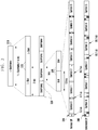
- FIG. 1 is a diagram illustrating an example of a scenario in which an Internet of things (IoT) communication system can operate.
- IoT Internet of things
- an IoT system occupies a narrow bandwidth in a frequency band, and for example, may use the minimum system bandwidth of 200 kHz (or 180 kHz) in both a downlink and an uplink. Due to the feature of the narrow band, the IoT system may spread through standalone, in the guard-band of the existing cellular system, or in the bandwidth of the existing cellular system.
- the IoT system may operate in at least one of a standalone mode 110 re-farmed in a GSM system, a mode 120 including a guard band in an LE system, and an in-band mode 130 operating in an LTE frequency bandwidth.
- the IoT system may spread within a certain PRB in the whole bandwidth, which may be called an in-band mode.
- PRB physical resource block
- the IoT system may spread within a guard-band region of the LTE system, which may be called a guard-band mode.
- the IoT system may spread in a standalone mode through re-farming of a GSM carrier having a bandwidth of 200 kHz.
- one independent IoT carrier 114 may be configured among GSM carriers 112.
- an IoT carrier 126 may be deployed between LTE carriers 122 and 124, and a guard band 128 may be deployed between them.
- an IoT carrier 134 may be deployed in an LTE carrier 132.
- FIG. 2 is a diagram illustrating a resource grid for signal transmission/reception in an IoT communication system.
- one PRB resource grid may be configured for one subframe.
- the PRB resource grid may have a different configuration in accordance with the length of a CP, and one subframe may include two slots.
- Each slot may include at least one resource element (RE) 210, and at least one common reference signal (CRS) 220 may be transmitted in the resource grid.
- RE resource element
- CRS common reference signal
- the IoT system supports an LTE in-band deployment, this system may be designed in consideration of compatibility and coexistence with the existing LTE system.
- system constituent elements used in the LTE for example, waveforms and subcarrier spacing may be reused for the IoT system.
- one PRB resource grid may be configured in a similar manner to that in the LTE system.
- FIG. 3 is a diagram illustrating an L subframe structure that can be operated in an IoT communication system.
- an L subframe 310 that can be operated in an IoT communication system may include two L slots 315. Further, each L slot 315 may include two subframes 320. One subframe 320 may include two slots. Further, in the case of a normal CP, the slot 325 may include 6 symbols 334, whereas in the case of an extended CP, the slot 325 may include 5 symbols 344. The lengths of the respective symbols and CPs are the same as those as illustrated.
- a longer subframe unit may be defined as the minimum scheduling unit, and for example, the L-subframe 310 may include 4 subframes (4 ms). If a short scheduling unit is necessary, an L-slot (2 ms) 315 may be considered.
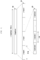
- FIG. 4 is a diagram illustrating an L super subframe structure that can be operated in an IoT communication system.
- an L superframe 400 that may be operated in the IoT communication system may include 32 L frames410, and each L frame may include 10 subframes 420.
- the L frame 410 may include 10 L-subframes 420, and may have duration of 40 ms.
- the duration of the L-frame may be aligned with a PBCH transmission time interval (TTI) in an LTE in which the PBCH is repeated four times for 40 ms.
- TTI transmission time interval
- One L-superframe 400 may include 32 L-frames 410 having duration of 1280 ms.
- FIG. 5 is a diagram illustrating a signal transmission scenario in an IoT communication system.
- a synchronization sequence may include a primary synchronization sequence (PSS) and a secondary synchronization sequence (SSS).
- PSS primary synchronization sequence
- SSS secondary synchronization sequence
- the MIB may include a limited amount of information of the system information.
- the remaining system information may be transmitted to a system information block (SIB). According to a coverage requirement condition, MIB and SIB frames may be repeatedly transmitted.
- FIG. 6 is a diagram illustrating a synchronization signal transmission resource in an IoT communication system.
- PSSs and/or SSSs may be repeatedly transmitted in a single subframe to improve the detection performance.
- the IoT device may acquire partial basic system information through detection of the PSS/SSS, for example, frame timing, CP length (normal CP or extended CP), FDD mode or TDD mode, and cell ID.
- CP length normal CP or extended CP
- FDD mode FDD mode
- TDD mode cell ID
- the PSS and SSS in different symbols in a subframe
- successive PSS/SSS detection may be guided in accordance with the CP length and the FDD/TDD mode.
- an IoT in-band mode when the PSS/SSS are transmitted, it is necessary that CRS transmission and PDCCH transmission related to LTE transmission are used. By arranging two successive symbols for the PSS transmission, the detection performance can be improved.
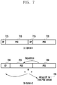
- FIG. 7 is a diagram illustrating an example of a method for transmitting a primary synchronization signal (PSS) in an IoT communication system.
- PSS primary synchronization signal
- PSSs 710 and 720 may be transmitted from two resources discriminated by CPs 705 and 715, and as indicated as option 2, two PSSs 735 and 740 may be successively transmitted after one CP 730.
- a portion of the first PSS 745 may be used as a virtual CP 745.
- signal portion "A" 745 may be considered as a virtual CP for the next PSS symbol.
- the PSS may be detected regardless of what CP length is used. Further, symbol level correlation can be used, and thus the PSS detection complexity can be reduced on the receiver side.
- the PSS/SSS may not use all symbols in a subframe
- the PBCH (MIB and/or SIB) and the PSS/SSS may be transmitted in the same subframe.
- the PSS/SSS signal may be used for channel estimation in order to decode the PBCH.
- FIG. 8 is a diagram illustrating an example of a method for transmitting a physical broadcast channel (PBCH) in an IoT communication system.
- PBCH physical broadcast channel
- remaining resource elements in subframes that are not occupied by PSSs 810 and 820 / SSSs 815 and 825 may be used for PBCH transmission.
- CRS resource elements should not be used for PBCH resource element mapping.
- the remaining elements excluding the PSS/SSS symbols may be used for the PBCH.
- the IoT system and the LTE system may share transmission power of a base station during downlink transmission.
- Power boosting of specific signals or channels for example, power boosting of PSS/SSS, MIB, SIB, or PDCCH, may be considered to improve the coverage performance of the in-band IoT system.
- IoT PSS/SSS and MIB transmission in consideration of a method for avoiding collisions with the existing LTE PSS/SSS and MIB transmissions as many as possible.
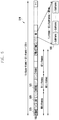
- FIG. 9 is a diagram illustrating an example of a method for transmitting a PSS, a secondary synchronization signal (SSS), and a master information block (MIB) in an IoT communication system.
- SSS secondary synchronization signal
- MIB master information block
- IoT transmission frame 910 and an LTE transmission frame 920 are illustrated.
- IoT PSS/SSS and MIB subframes and SIB subframes may be distributed in a proper method in order to avoid collisions in a time domain.
- PSS/SSS/MIB may be attempted to avoid collisions with LTE/PSS/SSS/MIB symbols as many as possible.
- the PSS/SSS may be located at the last symbol of the subframe that is different from that in the LTE system.
- FIG. 10 is a diagram illustrating an example of a method for transmitting PSS, SSS, and MIB in an IoT communication system operating time division duplex (TDD).
- TDD time division duplex
- an IoT transmission frame 1010 and an LTE transmission frame 1020 are illustrated.
- IoT PSS/SSS and MIB may be transmitted only in LTE DL subframes or specific frames. After acquisition of the system access and TDD UL/DL configurations, the use of other frames may be further acquired.
- the IoT PDCCH and PDSCH may occupy only DL subframes in the LTE TDD case.
- an IoT downlink frame structure may be proposed. This structure is aligned with the LTE system to become more suitable to an in-band deployment.
- one primary purpose is to avoid an influence exerted on the existing LTE terminals, and thus it is necessary that certain REs are protected by the LTE and are not to be used. More specifically, in the case of resources including information that should be essentially transmitted or received for the LTE terminals, they may not be used to transmit IoT terminal signals.
- PSS/SSS and PBCH for the IoT terminal, it is necessary to allocate them to the resources that do not collide with the existing LTE signals.
- the deployment of PSS, SSS, and M-PBCH may be selected to avoid collisions with LTE CRS, PRS, PSS, SSS, PDCCH, PCFICH, PHICH, and MBSFN.
- the MBSFN may be generated in subframes 1, 2, 3, 6, 7, and 8. Accordingly, in subframes 0, 4, 5, and 9, deployment of PSS/SSS and PBCH for the IoT terminal may be considered.
- FIG. 11 is a diagram illustrating an example of one configuration of a downlink frame in an IoT communication system.
- a structure in which PBCH 1110, SIB1 1115, PSS 1120, and SSS 1125 are transmitted for the IoT terminal may be applied in a similar manner to that in the LTE system.
- the PSS 1120 may be transmitted on subframe 9, and may be repeatedly transmitted every 20 ms.
- the PBCH 1110 may be transmitted on subframe 9, and may be repeatedly transmitted every 10 ms. If there is a dedicated resource for transmission of the SIB1 1115, it may be deployed in subframe 4 that is not occupied by the SSS.
- the resources remaining after the transmission may be shared for the PDCCH and PDSCH transmission.
- partial system information or configurations of the LTE system may be necessary to support more preferable coexistence between the LTE and the IoT. For example, if partial resources in the PRB of the IoT system are occupied by transmission of LTE system related information, the IoT system may transmit or receive a signal using the resource for transmission of the LTE system related information and information transmitted on the resource. Further, it is necessary that the IoT system performs signal transmission/reception to avoid partial resources among resources occupied by the LTE terminal.
- the CRS may be transmitted from partial REs in the whole bandwidth for channel estimation and RSRP measurement.
- the CRS of the LTE system may be transmitted even from the PRB in an in-band IoT operation mode.
- the IoT system can perform more reliable signal transmission/reception using the LTE CRS transmitted on the PRB allocated for the IoT system for the channel estimation.
- the transmitted CRS symbols may be determined based on at least one of a cell ID, slot index, CP length, and BW (e.g., N RB DL ). Further, the CRS transmission may be related to the number of antenna ports for the CRS transmission, that is, only antenna port 0, antenna ports 0 and 1, or antenna ports 0, 1, 2, and 3.
- an actual PRB index may be guided based on a PRB offset as a center frequency and bandwidth. Further, in an embodiment, the PRB index may be explicitly indicated. If a part or the whole of information related to the LTE CRS transmission is transmitted to a terminal related to the IoT system, the IoT terminal may receive the LTE CRS, and may perform channel estimation based on this.
- the IoT devices may use the LTE CRS for downlink channel estimation.
- the CP length may be determined in an IoT PSS/SSS detection process.
- the remaining parameters may be transferred in synchronization signals, MIB, or SIB.
- MIB synchronization signals
- SIB SIB
- All parameters may be signaled through synchronization signals and MIB. If the LTE CRS-related parameters are transmitted through the synchronization signals and MIB as described above, the IoT terminal may use the LTE CRS for channel estimation from the time when decoding the SIB. Also, the LTE cell ID may be guided, for example, through an IoT synchronization process in which the same cell ID is used in the IoT system. The remaining parameters, that is, the BW N RB DL and the CRS antenna port may be transmitted through MIBfmf In the same manner as the LTE MIB, three bits may be used for BW indication.
- the number of IoT CRS antenna ports is equal to the number of LTE CRS antenna ports.
- the numbers of antenna ports used by the LTE CRS and the IoT CRS may be partially different from each other. For example, maximally four antenna ports are used for the LTE CRS transmission, whereas maximally two antenna ports are used for the IoT CRS transmission. Even if the IoT terminals detect the use of two antenna ports related to the CRS reception in the PBCH decoding process, it is necessary to know the actual number of antenna ports and to consider this in a resource mapping process.
- the number of antenna ports (e.g., 1, 2, or 4) related to the LTE CRS may be indicated through separate 2-bit signaling.
- a one-bit indicator indicating whether the number of antenna ports related to the LTE CRS transmission is 4 or whether the number of antenna ports related to the LTE CRS transmission is equal to the number of IoT-related antenna ports may be transmitted to the terminal. More specifically, one bit may be used to indicate whetehr the number of antenna ports related to the LTE CRS transmission is 4, or may be used to indicate whether the number of IoT antenna ports is equal to the number of LTE antenna ports.
- Option 2 If the LTE-related cell ID cannot be indicated by the PSS/SSS of the IoT, inforamtion on the LTE-related cell ID may be included in the MIB. This means that the 9-bit cell ID and 3-bit BW are indicated by the MIB.
- the IoT PSS/SSS may indicate partial information of the LTE cell ID, and the remaining informtion may be additionally indicated by the MIB.
- the LTE cell SSS index may be indicated in the IoT PSS/SSS, and the LTE cell PSS index may be indicated in the MIB.
- the LTE cell ID may be guided by the IoT terminal after the IoT PSS/SSS and the MIB are received.
- This mapping rule provides a cell-specific CRS frequency shift v shift that is equal to that in the case of the LTE cell ID, in which it is profitable that the IoT cell ID notifies the IoT devices of at least CRS locations.
- partial information related to the LTE cell ID is signaled in the IoT terminal, and the remaining information may be determined by a predetermined relation or an equation.
- Option 4 In order to reduce a payload size of the MIB, for example, partial parameters, such as LTE-related cell ID and/or BW and/or CRS antenna ports, may be transmitted through the SIB.
- partial parameters such as LTE-related cell ID and/or BW and/or CRS antenna ports
- the LTE CRS is unable to be used for channel estimation in an SIB decoding process.
- the LTE CRS may be used for the channel estimation in the IoT system
- FIG. 12 is a diagram illustrating an example of a method for an IoT terminal to receive a signal.
- the IoT terminal may sense at least one of IoT-related PSS/SSS.
- the PSS/SSS may acquire LTE-related cell ID information through the synchronization signals.
- the IoT terminal may decode IoT-related MIB.
- LTE CRS-related information that is transmitted through the MIB may be acquired in accordance with the MIB decoding.
- the IoT terminal may decode IoT-related SIB.
- the IoT terminal may use the LTE CRS during SIB decoding. Further, the IoT terminal may acquire the LTE CRS-related information included in the SIB in accordance with the options.
- the IoT terminal may receive and process at least one of IoT-related PDCCH/PDSCH.
- the IoT terminal may receive and process one or more PDCCH/PDSCH based on the LTE CRS-related information received at the previous operation.
- FIG. 13 is a diagram illustrating another example of a method for an IoT terminal to receive a signal.
- the IoT terminal may sense at least one of IoT-related PSS/SSS.
- the PSS/SSS may acquire LTE-related cell ID information through the synchronization signals.
- the IoT terminal may acquire LTE CRS-related resource allocation information or location information.
- the IoT terminal may decode IoT-related MIB.
- LTE CRS-related information that is transmitted through the MIB may be acquired in accordance with the MIB decoding.
- the IoT terminal may acquire information on LTE CRS-related CRS values and the number of antenna ports.
- the IoT terminal may decode IoT-related SIB1.
- the SIB 1 may be an SIB set for the IoT terminal, and may include information, such as LTE CRS information.
- the IoT terminal may acquire LTE CRS-related information that has not been received at the previous operation.
- the IoT terminal may not use the LTE CRS information only during SIB1 decoding, but may acquire the LTE CRS information during decoding of other SIBs.
- the IoT terminal may decode the IoT-related SIB.
- the SIB may be shared with the LTE terminal, and during the SIB decoding, the LTE CRS-related information acquired at the previous operation may be used.
- the IoT terminal may receive and process at least one of IoT-related PDCCH/PDSCH.
- the IoT terminal may receive and process one or more PDCCH/PDSCH based on the LTE CRS-related information received at the previous operation.
- the IoT terminal may obtain LTE CRS information at the respective operations.
- CRS-related information amount acquired at the respective operations may differ in accordance with design options.
- acquired CRS information may be additionally used at the next operation.
- a different CRS information amount may be acquired at a different operation. For example, after the terminal acquires LTE CRS-related offset information, locations of resource elements occupied by the CRS may be guided.
- the base station may transmit IoT-related signal through non-CRS resource elements, and devices may also know that the non-CRS resource elements are merely processed (i.e., both a transmitter and a receiver are implicitly aligned to avoid transmission/reception of signals through the non-CRS resource elements). If the CRS information is sufficiently obtained, the CRS signals may be used for channel estimation in the process of decoding the PDCCH and PDSCH.
- Candidate PRBs for in-band IoT operation may be predefined based on a certain system requirement. An example is described in Table 1, and it may be considered that in order for the IoT terminals to easily find IoT signals at an initial cell searching, an offset between PRB center frequencies and 100 kHz channel raster offset are very small. More specifically, PRB candidate indexes for transmitting IoT PSS and SS in accordance with respective frequency bands are disclosed in Table 1. More specifically, Table 1 discloses indexes of candidate IoT PRBs for an in-band operation.
- the IoT PRB locations as described above may be used to derive sequence values used for CRS transmission. More specifically, the LTE CRS may use different sequence values in accordance with PRB indexes being transmitted, and if the terminal acquires such PRB information, it can know the sequence value used for the CRS transmission. As described above, the PRB location is required for the terminal to derive the CRS sequence values.
- the PRB index may be explicitly or implicitly indicated in NB-MIB.
- Option 1 In Table 1, 46 candidate PRBs exist in total. Accordingly, 6 bits may be used to indicate 64 candidates that may include the following cases: In the case of 46 candidates for in-band operation mode (as indicated in Table 1)
- related PRB information among 46 candidate PRBs may be transmitted to the terminal.
- Option 2 LTE CRS sequence values in a certain PRB are actually related to an offset to the center frequency. In relation to this, the details thereof will be described later.
- the same CRS sequence value may be used for PRBs having the same offset. Accordingly, even in the case of different PRB candidate groups having different frequency bands, the same CRS may be used if they have the same offset value. If the PRBs share the same offset for the center frequency, the same CRS sequence values may be used independent of BW. In the case of 15 MHz BW, the PRB offset includes all cases of the BW having odd-numbered PRBs, that is, all cases of 5 MHz and 15 MHz. In the case of 20 MHz BW, the PRB offset includes all cases of the BW having even-numbered PRBs, that is, all cases of 10 MHz and BW.
- the PRB indexes may be indicated through 30 pieces of offset information in total, and thus the PRB indexes can be indicated as information of 5 bits in total. Further, in an embodiment, in the case of the center frequency, related information can be acquired when the synchronization signal is received.
- Table 2 is a table indicating indexes of IoT PRB candidates for the in-band operation.
- CRS Index m 2*n_PRB, 2*n_PRB+1 CRS Index m' m ⁇ m + N RB max , DL ⁇ N RB DL (99,100), (89,90), (68,69), (39,40), (18,19), (119)
- FIG. 14 is a diagram illustrating PRB candidate resources to transmit IoT-related information in a communication system.
- carriers having bandwidths of 3 MHz, 5 MHz, 15 MHz, 10 MHz, and 20 MHz are illustrated.
- the respective bandwidths are aligned on the center frequency 1405, and parts of IoT PRB indexes on respective carriers are illustrated.
- the PRB indexes may be 2(1412) and 12(1410).
- 12 of 3 MHz 1410 has the same offset value 1416 as that of 17 of 5 MHz 1420 and 42 of 15 MHz 1430.
- the respective PRB indexes use CRS sequences, and through transmission of the offset information to the terminal, the terminal may acquire CRS sequence information.
- the respective PRB indexes are apart from the center frequency for the same offset, the CRS sequences corresponding to the PRB indexes are the same, and thus the base station can transmit the CRS sequence information to the terminal through a smaller number of information bits.
- the MIB may include contents related to the following CRS. More specifically, the LTE CRS-related information may be transmitted to the terminal through the MIB.
- the LTE CRS may be simultaneously transmitted to the RB in which the IoT operates, and the terminal may receive the LTE CRS-related information, and based on this, the terminal may use the LTE CRS for channel estimation or RRM measurement. More specifically, in order for the terminal to use the LTE CRS for the channel estimation, transmission power information of the LTE CRS is required.
- the transmission power information may be received through methods as follows.
- information on the relationship between the transmission power of the IoT-related RS and the transmission power of the LTE-related CRS may be transmitted from the base station to the terminal, and more specifically, the base station may transmit the offset value between the two transmission powers to the terminal.
- the corresponding information may be carried on the MIB or SIB to be transmitted through the PBCH, and may be notified through the PDSCH.
- the corresponding information may be carried on the MIB or SIB to be transmitted through the PBCH, and may be notified through the PDSCH.
- the base station should indicate two types of power ratios to the terminal), and the two types of information may be transmitted through a different channel (e.g., MIB or SIB) or through different channels.
- the terminal that has received this may perform channel estimation based on at least one of the transmission power offset value and the IoT-related RS transmission power information.
- partial resources and signals transmitted in the IoT PRB may be affected in accordance with the IoT transmission, or should not be interfered. Accordingly, resource-related configurations should be indicated in the IoT SIB.
- MBSFN MBSFN
- MCCH repetition period 32, 64, 128, or 256 frames
- MCCH offset (0 to 10) may be indicated in the SIB.
- PRS the PRS bandwidth N RB PRS , PRS configuration index I PRS , and the number of successive downlink subframes N PRS may be indicated in the case where the IoT PRB is used for the LTE PRS transmission.
- the system information required in the LTE system may be included in a specific system information block type N (SIB-N) in the IoT system that is the SIB type in which N is perdefined for the LTE system information.
- SIB-N system information block type N
- the IoT may update the SIB-N only in the case where the LTE-related system information is changed.
- the LTE system-related information may be signaled in the IoT terminal, and the signaling period of such a signal may be notified by the base station.
- FIG. 15 is a diagram illustrating an example of a method for a base station to transmit IoT-related information.
- the base station may transmit LTE-related information and IoT-related information to the terminal.
- the base station may determine resource information related to the LTE communication system. More specifically, the LTE system may determine resource allocation information for signal transmission/reception, and in this case, it may determine information on a resource region to be essentially transmitted to the terminal.
- the base station may determine resource information related to the IoT communication system.
- the base station may allocate resources related to the IoT communication system to a region excluding the resource region allocated for the LTE communication system.
- signal transmission resource related to the IoT communication system may be allocated to a region in which a signal, such as a CRS, can be used more easily in the LTE communication system.
- the base station may refer to at least one of a resource region already allocated for transmission of information related to the LTE communication system and a type of information transmitted from the corresponding resource.
- the base station may transmit at least one of the determined information to the terminal.
- the information may be transmitted through upper signaling or control signaling, and a part of the MIB may be transmitted through the SIB.
- the base station may receive channel information from the terminal.
- the channel information may include downlink channel information measured by the terminal, and channel information received from the IoT terminal may include channel information measured based on the CRS related to the LTE communication system.
- the base station may transmit control information and data information to the terminal based on at least one of the channel information and the information determined at the previous operation.
- LTE SFN information may be required in the IoT system in order to guide the resource occupied by the LTE, for example, the CSI-RS. Since the LTE SFN and the IoT SFN may not be always aligned with each other, the cycle thereof may have a different scale. Accordingly, in the case where the LTE SFN and the IoT SFN have different settings as described above, it is necessary for the base station to perform scheduling of such information to the terminal.
- FIG. 16 is a diagram illustrating an example of a method for setting an SFN offset in an LTE system and an IoT system.
- IoT SIB indicates the SFN offset, and this may be defined as a difference between IoT SFN 0 time and the last LTE SFN 0. Accordingly, it is necessary for the terminal to notify of the difference in time as described above, and in accordance with the minimum time unit of the time difference, the SFN offset may require a different bit amount for the indication.
- Option 1 If an offset is always a multiple of 40 ms, the information may be indicated through 8-bit SFN offset information.
- Option 2 In order to support a frame level difference of 10 ms, the information may be indicated through 10-bit SFN offset information.
- Option 3 In order to support a subframe (1 ms) difference, 14-bit SFN offset is necessary.
- FIG. 17 is a diagram illustrating another example of a method for setting an SFN offset in an LTE system and an IoT system.
- IoT SFN 1710 information related to IoT SFN 1710 and information related to LTE SFN 1720 are illustrated.
- the PRB index for IoT uplink transmission should be indicated in the SIB.
- the SIB in a certain IoT PRB may include different PRB indexes for not only in-band IoT but also guard-band IoT.
- the plurality of RPBs may independently operate, and the IoT system operates in a certain PRB for a downlink and in a certain PRB for an uplink.
- a single IoT system may have a plurality of PRBs for downlink or uplink. Inter-PRB hopping may be considered in this scenario to obtain additional merits of frequency diversity and scheduling flexibility.
- the transmission power of signals to be used for measurement for example, transmission power of synchronization signals and transmission power of a pilot or reference signal may be indicated in the SIB.
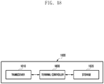
- FIG. 18 is a diagram illustrating a terminal according to an embodiment of the present disclosure.
- a terminal 1800 may include a transceiver 1810, a storage 1820, and a controller 1830.
- the transceiver 1810 may transmit and receive information related to the terminal, and may transmit/receive a signal to/from a base station.
- the storage 1820 may store therein at least one or a part of information related to the terminal and information transmitted/received through the transceiver 1810.
- the controller 1830 may control the overall operation of the terminal.
- the terminal may be an LTE terminal or an IoT terminal, and may be a terminal including features of the two terminals.
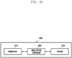
- FIG. 19 is a diagram illustrating a base station according to an embodiment of the present disclosure.
- a base station 1900 may include a transceiver 1910, a storage 1920, and a controller 1930.
- the transceiver 1910 may transmit and receive information related to the base station, and may transmit/receive a signal to/from a terminal.
- the storage 1920 may store therein at least one or a part of information related to the base station and information transmitted/received through the transceiver 1910.
- the controller 1930 may control the overall operation of the base station.
- the base station may transmit/receive signals for at least one of an LTE terminal and an IoT terminal, and may determine information transmitted to another communication system based on information corresponding to a specific communication system.
- the terminal may be an LTE terminal or an IoT terminal, and may be a terminal including features of the two terminals.
Applications Claiming Priority (11)
| Application Number | Priority Date | Filing Date | Title |
|---|---|---|---|
| US201562195425P | 2015-07-22 | 2015-07-22 | |
| US201562195571P | 2015-07-22 | 2015-07-22 | |
| US201562232840P | 2015-09-25 | 2015-09-25 | |
| US201562232860P | 2015-09-25 | 2015-09-25 | |
| US201562251378P | 2015-11-05 | 2015-11-05 | |
| US201662276468P | 2016-01-08 | 2016-01-08 | |
| US201662291246P | 2016-02-04 | 2016-02-04 | |
| US201662307818P | 2016-03-14 | 2016-03-14 | |
| US201662307904P | 2016-03-14 | 2016-03-14 | |
| PCT/KR2016/008051 WO2017014600A1 (fr) | 2015-07-22 | 2016-07-22 | Procédé et dispositif d'exploitation de dispositif de type machine dans un système de communication sans fil |
| EP16828104.6A EP3327973B1 (fr) | 2015-07-22 | 2016-07-22 | Procédé et dispositif d'exploitation de dispositif de type machine dans un système de communication sans fil |
Related Parent Applications (2)
| Application Number | Title | Priority Date | Filing Date |
|---|---|---|---|
| EP16828104.6A Division-Into EP3327973B1 (fr) | 2015-07-22 | 2016-07-22 | Procédé et dispositif d'exploitation de dispositif de type machine dans un système de communication sans fil |
| EP16828104.6A Division EP3327973B1 (fr) | 2015-07-22 | 2016-07-22 | Procédé et dispositif d'exploitation de dispositif de type machine dans un système de communication sans fil |
Publications (2)
| Publication Number | Publication Date |
|---|---|
| EP3567792A1 true EP3567792A1 (fr) | 2019-11-13 |
| EP3567792B1 EP3567792B1 (fr) | 2020-09-09 |
Family
ID=57834160
Family Applications (2)
| Application Number | Title | Priority Date | Filing Date |
|---|---|---|---|
| EP16828104.6A Active EP3327973B1 (fr) | 2015-07-22 | 2016-07-22 | Procédé et dispositif d'exploitation de dispositif de type machine dans un système de communication sans fil |
| EP19184102.2A Active EP3567792B1 (fr) | 2015-07-22 | 2016-07-22 | Procédé et dispositif pour faire fonctionner un dispositif de type machine dans un système de communication sans fil |
Family Applications Before (1)
| Application Number | Title | Priority Date | Filing Date |
|---|---|---|---|
| EP16828104.6A Active EP3327973B1 (fr) | 2015-07-22 | 2016-07-22 | Procédé et dispositif d'exploitation de dispositif de type machine dans un système de communication sans fil |
Country Status (5)
| Country | Link |
|---|---|
| US (1) | US10848283B2 (fr) |
| EP (2) | EP3327973B1 (fr) |
| KR (1) | KR102596103B1 (fr) |
| CN (1) | CN107852308B (fr) |
| WO (1) | WO2017014600A1 (fr) |
Families Citing this family (28)
| Publication number | Priority date | Publication date | Assignee | Title |
|---|---|---|---|---|
| US10454606B2 (en) * | 2015-07-22 | 2019-10-22 | Samsung Electronics Co., Ltd. | Method for operating IoT in cellular system and system therefor |
| CN111130744B (zh) * | 2015-12-16 | 2021-10-26 | 中兴通讯股份有限公司 | 数据的传输方法及装置 |
| CN106921468B (zh) * | 2015-12-28 | 2020-05-22 | 中兴通讯股份有限公司 | 一种信息传输方法及装置 |
| US10652068B2 (en) | 2016-01-12 | 2020-05-12 | Telefonaktiebolaget Lm Ericsson (Publ) | Synchronization signal detection |
| EP3403419A1 (fr) * | 2016-01-12 | 2018-11-21 | Nokia Solutions and Networks Oy | Sélection de cellule pour la signalisation d'exception dans des réseaux sans fil |
| JP6174735B1 (ja) * | 2016-02-04 | 2017-08-02 | 株式会社Nttドコモ | ユーザ装置及び通信方法 |
| CN107046721B (zh) * | 2016-02-05 | 2020-03-03 | 中兴通讯股份有限公司 | 传输信息的方法及装置 |
| CN109565842B (zh) * | 2016-07-20 | 2022-05-13 | 日本电气株式会社 | 用于信息传输和信息接收的方法和装置 |
| US10512050B2 (en) * | 2016-10-07 | 2019-12-17 | Qualcomm Incorporated | Synchronization and broadcast channel design with flexible bandwidth allocations |
| CN108075996A (zh) * | 2016-11-11 | 2018-05-25 | 索尼公司 | 控制装置、设备及方法、信号处理装置和方法及移动终端 |
| US10542445B2 (en) | 2017-02-06 | 2020-01-21 | Lg Electronics Inc. | Method and device for performing radio link monitoring by user equipment in wireless communication system |
| CN108632000B (zh) * | 2017-03-26 | 2020-10-02 | 上海朗帛通信技术有限公司 | 一种被用于窄带通信的用户设备、基站中的方法和装置 |
| CN106926648A (zh) * | 2017-03-28 | 2017-07-07 | 国动物联网技术(上海)有限公司 | 一种NB‑IoT无线胎压监测器 |
| WO2018178309A1 (fr) * | 2017-03-31 | 2018-10-04 | Telefonaktiebolaget Lm Ericsson (Publ) | Support pour porteuses se chevauchant en fréquence |
| CN115397006A (zh) * | 2017-04-10 | 2022-11-25 | 北京三星通信技术研究有限公司 | 窄带物联网接入的方法及用户设备 |
| CN108696384B (zh) | 2017-04-10 | 2022-09-16 | 北京三星通信技术研究有限公司 | 窄带物联网接入的方法及用户设备 |
| US11071073B2 (en) | 2017-04-14 | 2021-07-20 | Qualcomm Incorporated | Radio synchronization configuration in different operation modes |
| US10326576B2 (en) * | 2017-04-28 | 2019-06-18 | Qualcomm Incorporated | Reusing long-term evolution (LTE) reference signals for nested system operations |
| US11272510B2 (en) * | 2017-05-19 | 2022-03-08 | Qualcomm Incorporated | Channel and sync raster signaling |
| CN110430029B (zh) * | 2017-08-11 | 2020-11-20 | 华为技术有限公司 | 通信方法和装置 |
| CN109412767B (zh) | 2017-08-18 | 2021-01-15 | 中国移动通信有限公司研究院 | 参考信号的发射功率的指示、接收方法、网络设备及终端 |
| KR102429535B1 (ko) | 2017-09-26 | 2022-08-05 | 삼성전자주식회사 | 사물인터넷 장치의 네트워크 등록 방법 및 그 장치 |
| CN109818712B (zh) * | 2017-11-22 | 2021-02-19 | 大唐移动通信设备有限公司 | 一种基于窄带物联网的npdcch盲检方法和装置 |
| JP6943973B2 (ja) | 2018-04-16 | 2021-10-06 | エルジー エレクトロニクス インコーポレイティドLg Electronics Inc. | 無線通信システムにおいて信号を生成する方法及び装置 |
| CN111200487B (zh) * | 2018-11-20 | 2021-06-29 | 展讯通信(上海)有限公司 | 混合自动重传请求确认harq-ack的传输方法及装置 |
| KR102388027B1 (ko) * | 2018-12-26 | 2022-04-19 | 삼성전자 주식회사 | 무선통신 모듈의 시험 방법 및 상기 무선통신 모듈을 포함하는 전자 장치 |
| CN110445679B (zh) * | 2019-07-26 | 2020-06-26 | 南京大鱼半导体有限公司 | 通信测试方法、装置、存储介质及电子设备 |
| US20230134170A1 (en) * | 2021-11-03 | 2023-05-04 | At&T Intellectual Property I, L.P. | Mobile broadband and machine type communication network coexistence |
Citations (4)
| Publication number | Priority date | Publication date | Assignee | Title |
|---|---|---|---|---|
| WO2014101810A1 (fr) * | 2012-12-27 | 2014-07-03 | 夏普株式会社 | Procédé d'envoi et de réception d'informations système, station de base et équipement utilisateur |
| US20150071387A1 (en) * | 2013-09-12 | 2015-03-12 | Qualcomm Incorporated | Blind crs detection |
| WO2017035238A2 (fr) * | 2015-08-26 | 2017-03-02 | Qualcomm Incorporated | Techniques de communication en liaison descendante et de synchronisation pour des communications sans fil à bande étroite |
| WO2017123405A1 (fr) * | 2016-01-15 | 2017-07-20 | Qualcomm Incorporated | Conception matricielle pour opération à bande étroite pour des communications de type machine |
Family Cites Families (30)
| Publication number | Priority date | Publication date | Assignee | Title |
|---|---|---|---|---|
| CN101931485B (zh) | 2009-06-19 | 2014-02-12 | 北京三星通信技术研究有限公司 | 一种专用参考信号生成方法和装置 |
| CN102792717B (zh) | 2010-01-11 | 2016-08-03 | 黑莓有限公司 | 针对异构网络的控制信道干扰管理 |
| US8861430B2 (en) | 2011-08-11 | 2014-10-14 | Mediatek Inc. | Methods of point association for cooperative multiple point transmission |
| US8983391B2 (en) | 2011-08-12 | 2015-03-17 | Sharp Kabushiki Kaisha | Signaling power allocation parameters for uplink coordinated multipoint (CoMP) |
| KR101962245B1 (ko) | 2011-09-23 | 2019-03-27 | 삼성전자 주식회사 | 광대역 단말과 협대역 단말을 함께 운용하는 무선통신시스템에서 협대역 단말의 시스템 접속 방법 및 장치 |
| KR20130037507A (ko) | 2011-10-06 | 2013-04-16 | 삼성전자주식회사 | 다중 대역 다중 셀의 운영 방법 및 장치 |
| US9386535B2 (en) | 2011-10-26 | 2016-07-05 | Lg Electronics Inc. | Method for determining transmission power information of downlink subframe and apparatus therefor |
| EP2779495B1 (fr) | 2011-11-13 | 2021-03-24 | LG Electronics Inc. | Procédé et appareil de transmission d'informations de commande dans un système de communication sans fil |
| WO2013133682A1 (fr) * | 2012-03-09 | 2013-09-12 | 엘지전자 주식회사 | Procédé et dispositif pour la configuration d'un signal de référence |
| US9497003B2 (en) * | 2012-03-16 | 2016-11-15 | Nokia Technologies Oy | Common reference signal configuration for carrier aggregation |
| EP2829101A4 (fr) | 2012-03-21 | 2015-12-09 | Nokia Technologies Oy | Configuration de signaux de référence d'informations d'état de canal cycliques pour un nouveau type de porteuse à segment rétrocompatible |
| WO2014025139A1 (fr) * | 2012-08-10 | 2014-02-13 | 엘지전자 주식회사 | Procédé et appareil pour recevoir un signal sur la liaison descendante dans un système de communication sans fil |
| EP2962501A4 (fr) | 2013-03-29 | 2016-11-23 | Nec China Co Ltd | Procédés et appareils de transmission de données dans un système de communication sans-fil |
| WO2015012507A1 (fr) | 2013-07-26 | 2015-01-29 | 엘지전자 주식회사 | Procédé d'émission/réception pour appareil mtc |
| US11470619B2 (en) | 2013-08-07 | 2022-10-11 | Interdigital Patent Holdings, Inc. | Coverage enhancements of low cost MTC devices in uplink/downlink decoupled scenario |
| EP2950494B1 (fr) | 2013-08-27 | 2017-11-15 | Huawei Device Co., Ltd. | Procédé de transmission de données de liaison descendante dans une communication du type machine, station de base et équipement utilisateur |
| US9967842B2 (en) | 2013-11-11 | 2018-05-08 | Lg Electronics Inc. | Method for detecting synchronization signal for device-to-device (D2D) communication in wireless communication system and apparatus therefor |
| US9730196B2 (en) | 2014-07-29 | 2017-08-08 | Cable Television Laboratories, Inc. | LTE control channel reservation in RF bands with competing communication systems |
| US10263747B2 (en) * | 2015-01-06 | 2019-04-16 | Lg Electronics Inc. | Downlink signal reception method and user equipment, and downlink signal transmission method and base station |
| WO2016122268A1 (fr) * | 2015-01-30 | 2016-08-04 | 엘지전자 주식회사 | Procédé et appareil d'émission-réception de message de commande commun dans un système d'accès sans fil prenant en charge l'internet des choses en bande étroite |
| US9510134B2 (en) | 2015-04-02 | 2016-11-29 | Hyunyong Song | Method for performing machine type communication for the purpose of coverage improvement, apparatuses and systems for performing the same |
| US9860678B2 (en) * | 2015-05-22 | 2018-01-02 | Hyukjun Oh | Methods for performing machine type communication for the purpose of coverage enhancement, apparatuses and systems for performing the same |
| US20180146404A1 (en) * | 2015-05-29 | 2018-05-24 | Intel IP Corporation | Minimized system information transmission in wireless communication systems |
| US10334617B2 (en) | 2015-06-16 | 2019-06-25 | Qualcomm Incorporated | System information for enhanced machine type communication |
| US10575303B2 (en) | 2015-09-03 | 2020-02-25 | Qualcomm Incorporated | Uplink design for narrowband LTE (NB-LTE) |
| US11212760B2 (en) | 2015-09-24 | 2021-12-28 | Qualcomm Incorporated | Common synchronization channel design for narrowband communications |
| US10193734B2 (en) | 2015-12-24 | 2019-01-29 | Lg Electronics Inc. | Method for transceiving signal in a wireless communication system and apparatus for the same |
| US11424855B2 (en) | 2015-12-28 | 2022-08-23 | Qualcomm Incorporated | Physical broadcast channel (PBCH) and master information block (MIB) design |
| CN108370364B (zh) | 2016-01-09 | 2021-06-08 | 联想创新有限公司(香港) | 无线通信系统中的小区特定参考信号的生成设备及方法 |
| WO2017146342A1 (fr) | 2016-02-26 | 2017-08-31 | 엘지전자(주) | Procédé de réception d'informations de système dans un système de communication sans fil d'internet des objets à bande étroite, et dispositif associé |
-
2016
- 2016-07-22 WO PCT/KR2016/008051 patent/WO2017014600A1/fr active Application Filing
- 2016-07-22 EP EP16828104.6A patent/EP3327973B1/fr active Active
- 2016-07-22 EP EP19184102.2A patent/EP3567792B1/fr active Active
- 2016-07-22 US US15/745,592 patent/US10848283B2/en active Active
- 2016-07-22 CN CN201680042282.9A patent/CN107852308B/zh active Active
- 2016-07-22 KR KR1020160093704A patent/KR102596103B1/ko active IP Right Grant
Patent Citations (5)
| Publication number | Priority date | Publication date | Assignee | Title |
|---|---|---|---|---|
| WO2014101810A1 (fr) * | 2012-12-27 | 2014-07-03 | 夏普株式会社 | Procédé d'envoi et de réception d'informations système, station de base et équipement utilisateur |
| EP2941072A1 (fr) * | 2012-12-27 | 2015-11-04 | Sharp Kabushiki Kaisha | Procédé d'envoi et de réception d'informations système, station de base et équipement utilisateur |
| US20150071387A1 (en) * | 2013-09-12 | 2015-03-12 | Qualcomm Incorporated | Blind crs detection |
| WO2017035238A2 (fr) * | 2015-08-26 | 2017-03-02 | Qualcomm Incorporated | Techniques de communication en liaison descendante et de synchronisation pour des communications sans fil à bande étroite |
| WO2017123405A1 (fr) * | 2016-01-15 | 2017-07-20 | Qualcomm Incorporated | Conception matricielle pour opération à bande étroite pour des communications de type machine |
Non-Patent Citations (2)
| Title |
|---|
| MCC SUPPORT: "Draft Report of 3GPP TSG RAN WG1 #84 v0.1.0", vol. RAN WG1, no. Busan, South Korea; 20160411 - 20160415, 22 February 2016 (2016-02-22), XP051079501, Retrieved from the Internet <URL:http://www.3gpp.org/ftp/tsg_ran/WG1_RL1/TSGR1_84/Report/> [retrieved on 20160222] * |
| SAMSUNG: "PBCH coverage enhancements for low-cost MTC UEs", vol. RAN WG1, no. Chicago, USA; 20130415 - 20130419, 6 April 2013 (2013-04-06), XP050696995, Retrieved from the Internet <URL:http://www.3gpp.org/ftp/tsg_ran/WG1_RL1/TSGR1_72b/Docs/> [retrieved on 20130406] * |
Also Published As
| Publication number | Publication date |
|---|---|
| CN107852308B (zh) | 2021-01-05 |
| KR20170012143A (ko) | 2017-02-02 |
| EP3327973B1 (fr) | 2019-09-04 |
| EP3327973A4 (fr) | 2018-08-08 |
| CN107852308A (zh) | 2018-03-27 |
| WO2017014600A1 (fr) | 2017-01-26 |
| EP3327973A1 (fr) | 2018-05-30 |
| EP3567792B1 (fr) | 2020-09-09 |
| US10848283B2 (en) | 2020-11-24 |
| US20180212726A1 (en) | 2018-07-26 |
| KR102596103B1 (ko) | 2023-10-31 |
Similar Documents
| Publication | Publication Date | Title |
|---|---|---|
| EP3567792B1 (fr) | Procédé et dispositif pour faire fonctionner un dispositif de type machine dans un système de communication sans fil | |
| US11115145B2 (en) | Method for operating IoT in cellular system and system therefor | |
| US11516773B2 (en) | Methods and apparatus for supporting multiple services in wireless communication system | |
| EP3414955B1 (fr) | Procédé et appareil permettant une opération de synchronisation dans des réseaux de l'internet des objets cellulaires | |
| US20230156639A1 (en) | Method and device for communicating synchronization signal | |
| EP3698508B1 (fr) | Conception de séquence de signaux de réveil, et séquence de resynchronisation | |
| US11743949B2 (en) | Method and apparatus for random access in an integrated access and backhaul communication system | |
| JP2021108482A (ja) | 任意接続チャネル信号を送信する方法とユーザ機器、及び任意接続チャネル信号を受信する方法及び基地局 | |
| CN111756515B (zh) | 发射和接收用于侧链路信道状态信息获取的参考信号的方法和装置 | |
| CN109391426A (zh) | 资源位置的指示、接收方法及装置 | |
| KR20180114519A (ko) | 협대역 사물 인터넷에 대한 억세스를 위한 방법 및 사용자 단말기 | |
| KR20200131089A (ko) | 무선 통신 시스템에서 시스템 정보 블록 송수신 방법 및 장치 | |
| KR20150135272A (ko) | 인프라 장비, 이동 통신 네트워크, 시스템 및 방법 | |
| CN108063654B (zh) | 通信方法及终端、传输点 | |
| KR20200017229A (ko) | 무선 통신 시스템에서 데이터를 송수신하는 방법 및 장치 | |
| CN107124767B (zh) | 一种信号配置方法、信息处理方法及装置 | |
| US11317448B2 (en) | Method and apparatus for initial connection of wireless communication system | |
| US10674517B2 (en) | Method and apparatus for using resource information in wireless communication system | |
| KR20190112415A (ko) | 무선 통신 시스템에서 하향링크 전송을 검출하는 방법 및 장치 | |
| US20230088283A1 (en) | Method and apparatus for transmitting overlapping downlink and uplink channels in wireless communication system |
Legal Events
| Date | Code | Title | Description |
|---|---|---|---|
| PUAI | Public reference made under article 153(3) epc to a published international application that has entered the european phase |
Free format text: ORIGINAL CODE: 0009012 |
|
| STAA | Information on the status of an ep patent application or granted ep patent |
Free format text: STATUS: REQUEST FOR EXAMINATION WAS MADE |
|
| 17P | Request for examination filed |
Effective date: 20190703 |
|
| AC | Divisional application: reference to earlier application |
Ref document number: 3327973 Country of ref document: EP Kind code of ref document: P |
|
| AK | Designated contracting states |
Kind code of ref document: A1 Designated state(s): AL AT BE BG CH CY CZ DE DK EE ES FI FR GB GR HR HU IE IS IT LI LT LU LV MC MK MT NL NO PL PT RO RS SE SI SK SM TR |
|
| GRAP | Despatch of communication of intention to grant a patent |
Free format text: ORIGINAL CODE: EPIDOSNIGR1 |
|
| STAA | Information on the status of an ep patent application or granted ep patent |
Free format text: STATUS: GRANT OF PATENT IS INTENDED |
|
| INTG | Intention to grant announced |
Effective date: 20200406 |
|
| GRAS | Grant fee paid |
Free format text: ORIGINAL CODE: EPIDOSNIGR3 |
|
| GRAA | (expected) grant |
Free format text: ORIGINAL CODE: 0009210 |
|
| STAA | Information on the status of an ep patent application or granted ep patent |
Free format text: STATUS: THE PATENT HAS BEEN GRANTED |
|
| AC | Divisional application: reference to earlier application |
Ref document number: 3327973 Country of ref document: EP Kind code of ref document: P |
|
| AK | Designated contracting states |
Kind code of ref document: B1 Designated state(s): AL AT BE BG CH CY CZ DE DK EE ES FI FR GB GR HR HU IE IS IT LI LT LU LV MC MK MT NL NO PL PT RO RS SE SI SK SM TR |
|
| REG | Reference to a national code |
Ref country code: GB Ref legal event code: FG4D |
|
| REG | Reference to a national code |
Ref country code: AT Ref legal event code: REF Ref document number: 1312900 Country of ref document: AT Kind code of ref document: T Effective date: 20200915 Ref country code: CH Ref legal event code: EP |
|
| REG | Reference to a national code |
Ref country code: DE Ref legal event code: R096 Ref document number: 602016043970 Country of ref document: DE |
|
| REG | Reference to a national code |
Ref country code: IE Ref legal event code: FG4D |
|
| REG | Reference to a national code |
Ref country code: NL Ref legal event code: FP |
|
| REG | Reference to a national code |
Ref country code: LT Ref legal event code: MG4D |
|
| PG25 | Lapsed in a contracting state [announced via postgrant information from national office to epo] |
Ref country code: FI Free format text: LAPSE BECAUSE OF FAILURE TO SUBMIT A TRANSLATION OF THE DESCRIPTION OR TO PAY THE FEE WITHIN THE PRESCRIBED TIME-LIMIT Effective date: 20200909 Ref country code: SE Free format text: LAPSE BECAUSE OF FAILURE TO SUBMIT A TRANSLATION OF THE DESCRIPTION OR TO PAY THE FEE WITHIN THE PRESCRIBED TIME-LIMIT Effective date: 20200909 Ref country code: LT Free format text: LAPSE BECAUSE OF FAILURE TO SUBMIT A TRANSLATION OF THE DESCRIPTION OR TO PAY THE FEE WITHIN THE PRESCRIBED TIME-LIMIT Effective date: 20200909 Ref country code: HR Free format text: LAPSE BECAUSE OF FAILURE TO SUBMIT A TRANSLATION OF THE DESCRIPTION OR TO PAY THE FEE WITHIN THE PRESCRIBED TIME-LIMIT Effective date: 20200909 Ref country code: NO Free format text: LAPSE BECAUSE OF FAILURE TO SUBMIT A TRANSLATION OF THE DESCRIPTION OR TO PAY THE FEE WITHIN THE PRESCRIBED TIME-LIMIT Effective date: 20201209 Ref country code: GR Free format text: LAPSE BECAUSE OF FAILURE TO SUBMIT A TRANSLATION OF THE DESCRIPTION OR TO PAY THE FEE WITHIN THE PRESCRIBED TIME-LIMIT Effective date: 20201210 Ref country code: BG Free format text: LAPSE BECAUSE OF FAILURE TO SUBMIT A TRANSLATION OF THE DESCRIPTION OR TO PAY THE FEE WITHIN THE PRESCRIBED TIME-LIMIT Effective date: 20201209 |
|
| REG | Reference to a national code |
Ref country code: AT Ref legal event code: MK05 Ref document number: 1312900 Country of ref document: AT Kind code of ref document: T Effective date: 20200909 |
|
| PG25 | Lapsed in a contracting state [announced via postgrant information from national office to epo] |
Ref country code: PL Free format text: LAPSE BECAUSE OF FAILURE TO SUBMIT A TRANSLATION OF THE DESCRIPTION OR TO PAY THE FEE WITHIN THE PRESCRIBED TIME-LIMIT Effective date: 20200909 Ref country code: LV Free format text: LAPSE BECAUSE OF FAILURE TO SUBMIT A TRANSLATION OF THE DESCRIPTION OR TO PAY THE FEE WITHIN THE PRESCRIBED TIME-LIMIT Effective date: 20200909 Ref country code: RS Free format text: LAPSE BECAUSE OF FAILURE TO SUBMIT A TRANSLATION OF THE DESCRIPTION OR TO PAY THE FEE WITHIN THE PRESCRIBED TIME-LIMIT Effective date: 20200909 |
|
| PG25 | Lapsed in a contracting state [announced via postgrant information from national office to epo] |
Ref country code: EE Free format text: LAPSE BECAUSE OF FAILURE TO SUBMIT A TRANSLATION OF THE DESCRIPTION OR TO PAY THE FEE WITHIN THE PRESCRIBED TIME-LIMIT Effective date: 20200909 Ref country code: PT Free format text: LAPSE BECAUSE OF FAILURE TO SUBMIT A TRANSLATION OF THE DESCRIPTION OR TO PAY THE FEE WITHIN THE PRESCRIBED TIME-LIMIT Effective date: 20210111 Ref country code: RO Free format text: LAPSE BECAUSE OF FAILURE TO SUBMIT A TRANSLATION OF THE DESCRIPTION OR TO PAY THE FEE WITHIN THE PRESCRIBED TIME-LIMIT Effective date: 20200909 Ref country code: CZ Free format text: LAPSE BECAUSE OF FAILURE TO SUBMIT A TRANSLATION OF THE DESCRIPTION OR TO PAY THE FEE WITHIN THE PRESCRIBED TIME-LIMIT Effective date: 20200909 Ref country code: SM Free format text: LAPSE BECAUSE OF FAILURE TO SUBMIT A TRANSLATION OF THE DESCRIPTION OR TO PAY THE FEE WITHIN THE PRESCRIBED TIME-LIMIT Effective date: 20200909 |
|
| PG25 | Lapsed in a contracting state [announced via postgrant information from national office to epo] |
Ref country code: IS Free format text: LAPSE BECAUSE OF FAILURE TO SUBMIT A TRANSLATION OF THE DESCRIPTION OR TO PAY THE FEE WITHIN THE PRESCRIBED TIME-LIMIT Effective date: 20210109 Ref country code: ES Free format text: LAPSE BECAUSE OF FAILURE TO SUBMIT A TRANSLATION OF THE DESCRIPTION OR TO PAY THE FEE WITHIN THE PRESCRIBED TIME-LIMIT Effective date: 20200909 Ref country code: AL Free format text: LAPSE BECAUSE OF FAILURE TO SUBMIT A TRANSLATION OF THE DESCRIPTION OR TO PAY THE FEE WITHIN THE PRESCRIBED TIME-LIMIT Effective date: 20200909 Ref country code: AT Free format text: LAPSE BECAUSE OF FAILURE TO SUBMIT A TRANSLATION OF THE DESCRIPTION OR TO PAY THE FEE WITHIN THE PRESCRIBED TIME-LIMIT Effective date: 20200909 |
|
| REG | Reference to a national code |
Ref country code: DE Ref legal event code: R097 Ref document number: 602016043970 Country of ref document: DE |
|
| PG25 | Lapsed in a contracting state [announced via postgrant information from national office to epo] |
Ref country code: SK Free format text: LAPSE BECAUSE OF FAILURE TO SUBMIT A TRANSLATION OF THE DESCRIPTION OR TO PAY THE FEE WITHIN THE PRESCRIBED TIME-LIMIT Effective date: 20200909 |
|
| PLBE | No opposition filed within time limit |
Free format text: ORIGINAL CODE: 0009261 |
|
| STAA | Information on the status of an ep patent application or granted ep patent |
Free format text: STATUS: NO OPPOSITION FILED WITHIN TIME LIMIT |
|
| 26N | No opposition filed |
Effective date: 20210610 |
|
| PG25 | Lapsed in a contracting state [announced via postgrant information from national office to epo] |
Ref country code: DK Free format text: LAPSE BECAUSE OF FAILURE TO SUBMIT A TRANSLATION OF THE DESCRIPTION OR TO PAY THE FEE WITHIN THE PRESCRIBED TIME-LIMIT Effective date: 20200909 |
|
| PG25 | Lapsed in a contracting state [announced via postgrant information from national office to epo] |
Ref country code: IT Free format text: LAPSE BECAUSE OF FAILURE TO SUBMIT A TRANSLATION OF THE DESCRIPTION OR TO PAY THE FEE WITHIN THE PRESCRIBED TIME-LIMIT Effective date: 20200909 |
|
| REG | Reference to a national code |
Ref country code: CH Ref legal event code: PL |
|
| PG25 | Lapsed in a contracting state [announced via postgrant information from national office to epo] |
Ref country code: MC Free format text: LAPSE BECAUSE OF FAILURE TO SUBMIT A TRANSLATION OF THE DESCRIPTION OR TO PAY THE FEE WITHIN THE PRESCRIBED TIME-LIMIT Effective date: 20200909 |
|
| REG | Reference to a national code |
Ref country code: BE Ref legal event code: MM Effective date: 20210731 |
|
| PG25 | Lapsed in a contracting state [announced via postgrant information from national office to epo] |
Ref country code: LI Free format text: LAPSE BECAUSE OF NON-PAYMENT OF DUE FEES Effective date: 20210731 Ref country code: CH Free format text: LAPSE BECAUSE OF NON-PAYMENT OF DUE FEES Effective date: 20210731 |
|
| PG25 | Lapsed in a contracting state [announced via postgrant information from national office to epo] |
Ref country code: LU Free format text: LAPSE BECAUSE OF NON-PAYMENT OF DUE FEES Effective date: 20210722 |
|
| PG25 | Lapsed in a contracting state [announced via postgrant information from national office to epo] |
Ref country code: IE Free format text: LAPSE BECAUSE OF NON-PAYMENT OF DUE FEES Effective date: 20210722 Ref country code: BE Free format text: LAPSE BECAUSE OF NON-PAYMENT OF DUE FEES Effective date: 20210731 |
|
| PG25 | Lapsed in a contracting state [announced via postgrant information from national office to epo] |
Ref country code: CY Free format text: LAPSE BECAUSE OF FAILURE TO SUBMIT A TRANSLATION OF THE DESCRIPTION OR TO PAY THE FEE WITHIN THE PRESCRIBED TIME-LIMIT Effective date: 20200909 |
|
| PG25 | Lapsed in a contracting state [announced via postgrant information from national office to epo] |
Ref country code: HU Free format text: LAPSE BECAUSE OF FAILURE TO SUBMIT A TRANSLATION OF THE DESCRIPTION OR TO PAY THE FEE WITHIN THE PRESCRIBED TIME-LIMIT; INVALID AB INITIO Effective date: 20160722 |
|
| PGFP | Annual fee paid to national office [announced via postgrant information from national office to epo] |
Ref country code: NL Payment date: 20230621 Year of fee payment: 8 Ref country code: FR Payment date: 20230621 Year of fee payment: 8 |
|
| PG25 | Lapsed in a contracting state [announced via postgrant information from national office to epo] |
Ref country code: SI Free format text: LAPSE BECAUSE OF FAILURE TO SUBMIT A TRANSLATION OF THE DESCRIPTION OR TO PAY THE FEE WITHIN THE PRESCRIBED TIME-LIMIT Effective date: 20200909 |
|
| PGFP | Annual fee paid to national office [announced via postgrant information from national office to epo] |
Ref country code: GB Payment date: 20230620 Year of fee payment: 8 |
|
| PGFP | Annual fee paid to national office [announced via postgrant information from national office to epo] |
Ref country code: DE Payment date: 20230620 Year of fee payment: 8 |
|
| PG25 | Lapsed in a contracting state [announced via postgrant information from national office to epo] |
Ref country code: MK Free format text: LAPSE BECAUSE OF FAILURE TO SUBMIT A TRANSLATION OF THE DESCRIPTION OR TO PAY THE FEE WITHIN THE PRESCRIBED TIME-LIMIT Effective date: 20200909 |