EP3567664A1 - Metal hydride hydrogen storage arrangement for use in a fuel cell utility vehicle and method of manufacturing the same - Google Patents
Metal hydride hydrogen storage arrangement for use in a fuel cell utility vehicle and method of manufacturing the same Download PDFInfo
- Publication number
- EP3567664A1 EP3567664A1 EP19170287.7A EP19170287A EP3567664A1 EP 3567664 A1 EP3567664 A1 EP 3567664A1 EP 19170287 A EP19170287 A EP 19170287A EP 3567664 A1 EP3567664 A1 EP 3567664A1
- Authority
- EP
- European Patent Office
- Prior art keywords
- containers
- metal hydride
- storage arrangement
- hydrogen storage
- metal
- Prior art date
- Legal status (The legal status is an assumption and is not a legal conclusion. Google has not performed a legal analysis and makes no representation as to the accuracy of the status listed.)
- Granted
Links
Images


Classifications
-
- H—ELECTRICITY
- H01—ELECTRIC ELEMENTS
- H01M—PROCESSES OR MEANS, e.g. BATTERIES, FOR THE DIRECT CONVERSION OF CHEMICAL ENERGY INTO ELECTRICAL ENERGY
- H01M8/00—Fuel cells; Manufacture thereof
- H01M8/06—Combination of fuel cells with means for production of reactants or for treatment of residues
- H01M8/0606—Combination of fuel cells with means for production of reactants or for treatment of residues with means for production of gaseous reactants
- H01M8/065—Combination of fuel cells with means for production of reactants or for treatment of residues with means for production of gaseous reactants by dissolution of metals or alloys; by dehydriding metallic substances
-
- H—ELECTRICITY
- H01—ELECTRIC ELEMENTS
- H01M—PROCESSES OR MEANS, e.g. BATTERIES, FOR THE DIRECT CONVERSION OF CHEMICAL ENERGY INTO ELECTRICAL ENERGY
- H01M8/00—Fuel cells; Manufacture thereof
- H01M8/04—Auxiliary arrangements, e.g. for control of pressure or for circulation of fluids
- H01M8/04082—Arrangements for control of reactant parameters, e.g. pressure or concentration
- H01M8/04201—Reactant storage and supply, e.g. means for feeding, pipes
- H01M8/04216—Reactant storage and supply, e.g. means for feeding, pipes characterised by the choice for a specific material, e.g. carbon, hydride, absorbent
-
- B—PERFORMING OPERATIONS; TRANSPORTING
- B60—VEHICLES IN GENERAL
- B60L—PROPULSION OF ELECTRICALLY-PROPELLED VEHICLES; SUPPLYING ELECTRIC POWER FOR AUXILIARY EQUIPMENT OF ELECTRICALLY-PROPELLED VEHICLES; ELECTRODYNAMIC BRAKE SYSTEMS FOR VEHICLES IN GENERAL; MAGNETIC SUSPENSION OR LEVITATION FOR VEHICLES; MONITORING OPERATING VARIABLES OF ELECTRICALLY-PROPELLED VEHICLES; ELECTRIC SAFETY DEVICES FOR ELECTRICALLY-PROPELLED VEHICLES
- B60L50/00—Electric propulsion with power supplied within the vehicle
- B60L50/50—Electric propulsion with power supplied within the vehicle using propulsion power supplied by batteries or fuel cells
- B60L50/70—Electric propulsion with power supplied within the vehicle using propulsion power supplied by batteries or fuel cells using power supplied by fuel cells
-
- C—CHEMISTRY; METALLURGY
- C01—INORGANIC CHEMISTRY
- C01B—NON-METALLIC ELEMENTS; COMPOUNDS THEREOF; METALLOIDS OR COMPOUNDS THEREOF NOT COVERED BY SUBCLASS C01C
- C01B3/00—Hydrogen; Gaseous mixtures containing hydrogen; Separation of hydrogen from mixtures containing it; Purification of hydrogen; Reversible storage of hydrogen
- C01B3/0005—Reversible storage of hydrogen, e.g. by hydrogen getters or electrodes
- C01B3/001—Reversible storage of hydrogen, e.g. by hydrogen getters or electrodes characterised by the uptaking media; Treatment thereof
- C01B3/0018—Inorganic elements or compounds, e.g. oxides, nitrides, borohydrides or zeolites; Solutions thereof
- C01B3/0026—Metals or metal hydrides
-
- F—MECHANICAL ENGINEERING; LIGHTING; HEATING; WEAPONS; BLASTING
- F17—STORING OR DISTRIBUTING GASES OR LIQUIDS
- F17C—VESSELS FOR CONTAINING OR STORING COMPRESSED, LIQUEFIED OR SOLIDIFIED GASES; FIXED-CAPACITY GAS-HOLDERS; FILLING VESSELS WITH, OR DISCHARGING FROM VESSELS, COMPRESSED, LIQUEFIED, OR SOLIDIFIED GASES
- F17C11/00—Use of gas-solvents or gas-sorbents in vessels
- F17C11/005—Use of gas-solvents or gas-sorbents in vessels for hydrogen
-
- B—PERFORMING OPERATIONS; TRANSPORTING
- B60—VEHICLES IN GENERAL
- B60Y—INDEXING SCHEME RELATING TO ASPECTS CROSS-CUTTING VEHICLE TECHNOLOGY
- B60Y2200/00—Type of vehicle
- B60Y2200/10—Road Vehicles
- B60Y2200/15—Fork lift trucks, Industrial trucks
-
- B—PERFORMING OPERATIONS; TRANSPORTING
- B60—VEHICLES IN GENERAL
- B60Y—INDEXING SCHEME RELATING TO ASPECTS CROSS-CUTTING VEHICLE TECHNOLOGY
- B60Y2400/00—Special features of vehicle units
- B60Y2400/20—Energy converters
- B60Y2400/202—Fuel cells
-
- F—MECHANICAL ENGINEERING; LIGHTING; HEATING; WEAPONS; BLASTING
- F17—STORING OR DISTRIBUTING GASES OR LIQUIDS
- F17C—VESSELS FOR CONTAINING OR STORING COMPRESSED, LIQUEFIED OR SOLIDIFIED GASES; FIXED-CAPACITY GAS-HOLDERS; FILLING VESSELS WITH, OR DISCHARGING FROM VESSELS, COMPRESSED, LIQUEFIED, OR SOLIDIFIED GASES
- F17C2205/00—Vessel construction, in particular mounting arrangements, attachments or identifications means
- F17C2205/01—Mounting arrangements
- F17C2205/0123—Mounting arrangements characterised by number of vessels
- F17C2205/013—Two or more vessels
- F17C2205/0134—Two or more vessels characterised by the presence of fluid connection between vessels
- F17C2205/0142—Two or more vessels characterised by the presence of fluid connection between vessels bundled in parallel
-
- F—MECHANICAL ENGINEERING; LIGHTING; HEATING; WEAPONS; BLASTING
- F17—STORING OR DISTRIBUTING GASES OR LIQUIDS
- F17C—VESSELS FOR CONTAINING OR STORING COMPRESSED, LIQUEFIED OR SOLIDIFIED GASES; FIXED-CAPACITY GAS-HOLDERS; FILLING VESSELS WITH, OR DISCHARGING FROM VESSELS, COMPRESSED, LIQUEFIED, OR SOLIDIFIED GASES
- F17C2270/00—Applications
- F17C2270/01—Applications for fluid transport or storage
- F17C2270/0165—Applications for fluid transport or storage on the road
- F17C2270/0168—Applications for fluid transport or storage on the road by vehicles
-
- F—MECHANICAL ENGINEERING; LIGHTING; HEATING; WEAPONS; BLASTING
- F28—HEAT EXCHANGE IN GENERAL
- F28F—DETAILS OF HEAT-EXCHANGE AND HEAT-TRANSFER APPARATUS, OF GENERAL APPLICATION
- F28F7/00—Elements not covered by group F28F1/00, F28F3/00 or F28F5/00
- F28F7/02—Blocks traversed by passages for heat-exchange media
-
- H—ELECTRICITY
- H01—ELECTRIC ELEMENTS
- H01M—PROCESSES OR MEANS, e.g. BATTERIES, FOR THE DIRECT CONVERSION OF CHEMICAL ENERGY INTO ELECTRICAL ENERGY
- H01M2250/00—Fuel cells for particular applications; Specific features of fuel cell system
- H01M2250/20—Fuel cells in motive systems, e.g. vehicle, ship, plane
-
- Y—GENERAL TAGGING OF NEW TECHNOLOGICAL DEVELOPMENTS; GENERAL TAGGING OF CROSS-SECTIONAL TECHNOLOGIES SPANNING OVER SEVERAL SECTIONS OF THE IPC; TECHNICAL SUBJECTS COVERED BY FORMER USPC CROSS-REFERENCE ART COLLECTIONS [XRACs] AND DIGESTS
- Y02—TECHNOLOGIES OR APPLICATIONS FOR MITIGATION OR ADAPTATION AGAINST CLIMATE CHANGE
- Y02E—REDUCTION OF GREENHOUSE GAS [GHG] EMISSIONS, RELATED TO ENERGY GENERATION, TRANSMISSION OR DISTRIBUTION
- Y02E60/00—Enabling technologies; Technologies with a potential or indirect contribution to GHG emissions mitigation
- Y02E60/30—Hydrogen technology
- Y02E60/32—Hydrogen storage
-
- Y—GENERAL TAGGING OF NEW TECHNOLOGICAL DEVELOPMENTS; GENERAL TAGGING OF CROSS-SECTIONAL TECHNOLOGIES SPANNING OVER SEVERAL SECTIONS OF THE IPC; TECHNICAL SUBJECTS COVERED BY FORMER USPC CROSS-REFERENCE ART COLLECTIONS [XRACs] AND DIGESTS
- Y02—TECHNOLOGIES OR APPLICATIONS FOR MITIGATION OR ADAPTATION AGAINST CLIMATE CHANGE
- Y02E—REDUCTION OF GREENHOUSE GAS [GHG] EMISSIONS, RELATED TO ENERGY GENERATION, TRANSMISSION OR DISTRIBUTION
- Y02E60/00—Enabling technologies; Technologies with a potential or indirect contribution to GHG emissions mitigation
- Y02E60/30—Hydrogen technology
- Y02E60/50—Fuel cells
-
- Y—GENERAL TAGGING OF NEW TECHNOLOGICAL DEVELOPMENTS; GENERAL TAGGING OF CROSS-SECTIONAL TECHNOLOGIES SPANNING OVER SEVERAL SECTIONS OF THE IPC; TECHNICAL SUBJECTS COVERED BY FORMER USPC CROSS-REFERENCE ART COLLECTIONS [XRACs] AND DIGESTS
- Y02—TECHNOLOGIES OR APPLICATIONS FOR MITIGATION OR ADAPTATION AGAINST CLIMATE CHANGE
- Y02P—CLIMATE CHANGE MITIGATION TECHNOLOGIES IN THE PRODUCTION OR PROCESSING OF GOODS
- Y02P70/00—Climate change mitigation technologies in the production process for final industrial or consumer products
- Y02P70/50—Manufacturing or production processes characterised by the final manufactured product
-
- Y—GENERAL TAGGING OF NEW TECHNOLOGICAL DEVELOPMENTS; GENERAL TAGGING OF CROSS-SECTIONAL TECHNOLOGIES SPANNING OVER SEVERAL SECTIONS OF THE IPC; TECHNICAL SUBJECTS COVERED BY FORMER USPC CROSS-REFERENCE ART COLLECTIONS [XRACs] AND DIGESTS
- Y02—TECHNOLOGIES OR APPLICATIONS FOR MITIGATION OR ADAPTATION AGAINST CLIMATE CHANGE
- Y02T—CLIMATE CHANGE MITIGATION TECHNOLOGIES RELATED TO TRANSPORTATION
- Y02T90/00—Enabling technologies or technologies with a potential or indirect contribution to GHG emissions mitigation
- Y02T90/40—Application of hydrogen technology to transportation, e.g. using fuel cells
Definitions
- the invention relates to a metal hydride hydrogen storage and supply arrangement integrated for use in a fuel cell utility vehicle, and more particularly but not exclusively to a metal hydride hydrogen storage and supply arrangement for use in utility vehicles, for example forklifts, which require counterweight to provide a low centre of gravity / balancing for the safe operation of the vehicle.
- MH metal hydrides
- the "low-temperature" intermetallic hydrides with hydrogen storage capacities below 2 wt% i.e. storage of 1 kg H requires more than 50 kg of the MH material
- the low weight capacity of intermetallic hydrides which is usually considered as a major disadvantage to their use in vehicular hydrogen storage applications, is an advantage for use in heavy duty utility vehicles.
- metal hydrides for the storage of hydrogen fuel where the MH additionally serves as a ballast / counterweight
- hydrogen engine system with metal hydride container US5,082,048 to Iwaki et al
- hydrogen hydride keel for ships US5,445,099 to Rendina
- industrial truck with a hydrogen storage arrangement EP1215163 B1 to Pfeiffer et al
- material handling vehicle including integrated hydrogen storage ( US 2009/0166110 A1 to Gregory et al ).
- a metal hydride hydrogen storage material in a plurality of metal hydride containers that supply hydrogen fuel to a hydrogen engine or fuel cell, and which are equipped with means for heating the storage arrangements to provide H 2 desorption from the metal hydride by transferring the heat released during the engine / fuel cell operation to the MH containers.
- ballast is usually made as a metal body made of cast iron which leaves quite a small vacant space that is mostly occupied by CGH2 hydrogen storage arrangement.
- a metal hydride hydrogen storage system for forklift applications was developed by Hawaii Hydrogen Carriers LLC, together with other companies and institutions, within US DoE funded project "Low Cost, Metal Hydride Hydrogen Storage System for Forklift Applications". See C. Polson, C. Jensen. Presentation at US DOE Annual Merit Review Meeting, May 11, 2011, Project ID #: ST 09 , D. Brayton, A. Narvaez. Presentation at US DOE Annual Merit Review Meeting, May 15, 2013, Project ID #: ST 095 and A. Narvaez. Presentation at US DOE Annual Merit Review Meeting, June 18, 2014, Project ID #: ST 095 .
- the system / metal hydride hydrogen storage arrangement is made as a staggered array (5 x 8) of tubular containers (2" in the diameter, 40 in total) filled with an AB 5 -type metal hydride material and placed in a water storage arrangement equipped with inlet and outlet cooling / heating water ports.
- the hydride storage arrangement has dimensions 470 mm (L) x 700 mm (W) x 370 mm (H), contains about 2 kg ( ⁇ 20 Nm 3 ) H 2 and has an estimated weight of about 500 kg when filled with water.
- a metal hydride hydrogen storage arrangement suitable for use in a fuel cell utility vehicle, the storage arrangement including:
- the filler body prefferably located in close proximity of external surfaces of the containers and the heat transfer means.
- the heat transfer means may be heating and/or cooling means. Note that in the specification, the terms heat transfer means and heating / cooling means are used interchangeably.
- the filler body may be in the form of a metal body formed by a melting and solidification of a metal or an alloy.
- the metal or the alloy may have a high density, for example > 8 kg/L (e.g. 8.64 kg/L - Cadmium), preferably > 11 kg/L (e.g. 11.34 kg/L - Lead).
- the metal or the alloy may have a high thermal conductivity, for example > 35 W/(m K) (e.g. Lead), preferably 100-120 W/(m K) (e.g. Cadmium, Zinc, multicomponent alloys).
- a high thermal conductivity for example > 35 W/(m K) (e.g. Lead), preferably 100-120 W/(m K) (e.g. Cadmium, Zinc, multicomponent alloys).
- the metal or the alloy may have a melting / solidification point below the maximum allowed operation temperature of the metal hydride container, but above the activation temperature of the metal hydride material. More particularly, the metal or the alloy which forms the filling body may be lead or a lead-containing alloy with a melting point between 150 and 350 °C, in which case the activation temperature of the metal hydride material may be between 100 and 300 °C.
- a further feature of the invention provides for the metal hydride container to comprise an all-welded stainless steel structure.
- the heat transfer means to include a heat transfer fluid conduit, for example tubing, for conveying a heat transfer fluid.
- the tubing may be staggered in between the metal hydride containers.
- a metal hydride hydrogen storage arrangement suitable for use in a fuel cell utility vehicle, the method including the steps of:
- step of filling the inner space with a filler material includes the steps of:
- the pre-assembly of the metal hydride hydrogen storage arrangement may be opened from the top, and the pre-heating step may be carried out by directing a flow of hot air to the top of the pre-assembly.
- the flow of hot air may emanate from a gas burner which may be placed in an air-boosting chamber equipped with an air blower.
- the step of pre-heating the pre-assembly to be carried out until reaching a temperature of between a half and two thirds of the melting point of the metal or the alloy which forms the filler body.
- the metal or the alloy may be pre-melted, and the filing step may be carried out by an open casting of the melt into the pre-assembly of the metal hydride hydrogen storage arrangement.
- the step of pre-heating the pre-assembly may be carried out until reaching a temperature above the melting point of the metal or the alloy which forms the filer body.
- filling the metal or the alloy may be carried out by the loading of solid pieces of the metal or the alloy into the inner space of the pre-assembly, followed by its melting inside the pre-assembly of the metal hydride hydrogen storage arrangement.
- the pressurised gas for filling the inner volume of the containers may be hydrogen.
- the pressurised gas may be an inert gas, or a mixture of hydrogen and an inert gas.
- the method may include a final activation procedure which includes the steps of:
- a further aspect of the invention comprises a metal hydride hydrogen storage arrangement comprising a plurality of storage arrangement as described above.
- the storage arrangement 10, shown in cross-section in Figure 1 includes a plurality of metal hydride containers 11.
- metal hydride containers 11 Any known layout of metal hydride (“MH”) containers with external heating / cooling can be used in the invention, and the invention is therefore not limited to a particular layout of configuration.
- MH metal hydride
- tubular containers that are heated and cooled from the outside is a preferable configuration, as this is the simplest and most cost effective option.
- the gas input / output pipelines of the containers 11 are connected to a common gas manifold 12 that terminates in an external pipeline 13, which enables H 2 charging and discharging of the storage arrangement 10 during absorption or desorption in or out of the MH containers, respectively.
- the storage arrangement must include heat transfer means 14 for cooling the MH containers 11 during H 2 charging.
- the storage arrangement also requires means for heating the containers when discharging H 2 .
- the maximum efficiency of the cooling and the heating is achieved when the heat transfer means (in the form of heating / cooling means 14) are uniformly distributed in between the MH containers 11 in order to provide approximately the same heat transfer distances to the different containers.
- the space between the metal hydride containers 11 and the heating / cooling means 14 is filled with a metal or an alloy which forms a filler body 17 made of a solidified molten metal or alloy, and which closely adjoins the external surfaces of the MH containers 11 and the heating / cooling means 14. Since the metal hydride storage arrangement simultaneously serves as hydrogen storage medium and as a ballast, the metal or alloy should have a high density to provide maximum weight of the storage arrangement at a minimal volume. The metal or alloy also has to have a high thermal conductivity to maximise the rate of the heat exchange between the MH containers 11 and the heating / cooling means 14.
- the filler body 17 envelops all other components of the MH storage arrangement including the MH containers 11, the gas manifold 12 and the heating / cooling means 14. Only the ends, 15 and 16, of the heat transfer conduit 14 and an end 13 of the external pipeline protrudes from the filler body 17. Although this does not have to be the case, this embodiment is preferred due to a number of reasons including the sealing of possible micro-leaks in the pipelines and their joints during formation of the filler body 17. However, other embodiments may include configurations where the filler body only partially envelops other components of the MH storage arrangement.
- criteria determining the size of the filling body / degree of the envelopment include: (i) the weight required to be added to the fuel cell power module, (ii) density of the metal or alloy which forms the filler body; and (iii) space available to the hydrogen storage arrangement. All these criteria can be taken into account during the design stage to yield target dimensions of all the components (11-17) of the storage arrangement.
- the most effective way of manufacturing the hydrogen storage arrangement schematically shown in Figure 1 is to fill the space between the MH containers 11 and the heating / cooling means 14 with the molten metal or alloy, followed by its solidification to form the filling body 17.
- Such a procedure is characterised by relatively low labour consumption and costs as compared to alternative ones (e.g., machining of a solid piece of metal to create channels for the MH material and the heating / cooling fluid). It also provides good thermal contact between the filler body 17, the MH containers 11 and the heating / cooling means 14. The details of the filling procedure will be described below.
- the melting / solidification point (MP) of the metal or alloy for making the filler body 17 must not be higher than the maximum allowed operation temperature of the MH container 11.
- MP melting / solidification point
- stainless steel is used as a material to manufacture the MH containers 11. Since any additional joint (gasket, sealed thread coupling, etc.) reduces the temperature rating, the preference is given to the all-welded stainless steel structure.
- lead alloys with various compositions therefore allows one to vary the melting / solidification point in relatively wide limits. Apart from the melting point, the selection criteria for the lead alloys for making the filler body include its low cost and reasonably high thermal conductivity.
- the melting / solidification point of the metal or alloy for making the filler body 17 also has to be higher than the activation temperature of the MH material loaded in the metal hydride containers 11.
- the operating temperature of the MH material must be below its activation temperature, and the H 2 equilibrium pressure for the MH material at the operating temperature must be higher than the atmospheric pressure to provide H 2 supply to a fuel cell stack.
- the material for making the filler body 17 is lead or a lead-containing alloy with melting / solidification point between 150 and 350 °C, and the activation temperature of the metal hydride material is between 100 and 300 °C.
- Most of the commonly used hydrogen storage alloys e.g. AB 5 - and AB 2 -type) satisfy the latter criterion.
- AB 5 - and AB 2 -type satisfy the latter criterion.
- these alloys have a hydrogen equilibrium pressure in excess of 1 bar (100 kPa), which makes them suitable for the use in this invention.
- the manufacturing of the MH hydrogen storage arrangement in accordance with the present invention entails a procedure of forming the filler body 17 by the use of "melting - solidification" route. This procedure is crucial, and the method of manufacturing the MH storage arrangement by way of this procedure is described below.
- the storage arrangement should also be subjected to the following final activation procedure:
- the MH storage arrangement and the method of manufacturing thereof as described above can be made as a single unit ready for integration into a utility vehicle.
- the storage arrangement can be made up of an assembly of several smaller modules made as described above. This option adds flexibility in making MH hydrogen storage arrangements for various utility vehicles based on a unified modular design that is beneficial for mass production.
- a metal hydride hydrogen storage arrangement should:
- tubular metal hydride containers made as all-welded stainless steel structures, which will in use be filled with an AB 2 -type hydrogen storage alloy characterised by a hydrogen equilibrium pressure of about 10 bar at room temperature and an activation temperature of between 150 and 300 °C.
- Each container is 51.3 mm in diameter, 800 mm in length, 8.9 kg in weight (incl. MH material) and has a hydrogen storage capacity of about 0.5 Nm 3 .
- the assembly of the 40 MH containers staggered into a 200L volume will have a weight of 356 kg.
- the empty space between containers been filled with water (as per one of the prior art configurations)
- the total weight of the hydrogen storage arrangement would have amounted to about 490 kg, which is far below the lower weight constraint of the application.
- the storage arrangement is an assembly of 8 modules (MH cassettes) each comprising of 5 MH containers as described above.
- a 15 mm OD stainless steel heating / cooling pipe extends between the cassettes and the empty space is occupied by a filler body made of lead.
- the total storage arrangement dimensions (8 cassettes packed together) are 704 mm (L) x 960 mm (W) x 264 mm (H) that corresponds to the total volume below 170L.
- the target weight of one cassette was calculated to be between 125 and 187.5 kg, with the combined weight therefore exceeding the 1 ton requirement.
- Figure 4 shows a pre-assembly of the MH cassette prepared for the casting of the lead filler body.
- the MH containers 11, together with the heating / cooling pipe 14, are pre-assembled in a removable shell 18 made of stainless steel sheets, and which envelopes the MH containers and the pipes with the exception of the gas manifold 12 and the welded joints between the cooling pipes 14.
- the total weight of the cassette / pre-assembly before casting of the lead filler body was about 45 kg.
- the gaps in the shell were sealed by a high-temperature sealant to avoid spillage of the molten lead during the manufacturing process.
- the present invention offers a design and a method of manufacturing a compact hydrogen storage arrangement which will be useful in a number of fuel cell powered heavy duty vehicles including material handling units, mining locomotives, and marine applications.
- the use of the invention will also result in the reduction or elimination of space occupied by ballast in these kind of vehicles, thus adding flexibility to the layout of other components (stack + BoP) of the fuel cell power modules which can in turn be improved in terms of ease of assembly and service.
- the solution of the problem of the increase of space available for the placement of a fuel cell and its BoP within weight and space constrains of a utility vehicle resides in "merging" the ballast and the metal hydride hydrogen storage system in an integrated design resulting in a unified hydrogen storage arrangement.
- the invention is inventive, in that it departs from the conventional design methodology of MH storage systems, in which the aim is to reduce the weight of the fuel storage arrangements.
- the integrated system will also provide efficient heating and cooling of the MH material to provide sufficient rates of H 2 desorption / absorption during the H 2 discharge / charge.
Landscapes
- Engineering & Computer Science (AREA)
- Chemical & Material Sciences (AREA)
- Life Sciences & Earth Sciences (AREA)
- Sustainable Energy (AREA)
- Sustainable Development (AREA)
- Mechanical Engineering (AREA)
- General Engineering & Computer Science (AREA)
- Chemical Kinetics & Catalysis (AREA)
- General Chemical & Material Sciences (AREA)
- Manufacturing & Machinery (AREA)
- Electrochemistry (AREA)
- Organic Chemistry (AREA)
- Transportation (AREA)
- Power Engineering (AREA)
- Thermal Sciences (AREA)
- Physics & Mathematics (AREA)
- Geology (AREA)
- Environmental & Geological Engineering (AREA)
- General Life Sciences & Earth Sciences (AREA)
- Inorganic Chemistry (AREA)
- Combustion & Propulsion (AREA)
- Filling Or Discharging Of Gas Storage Vessels (AREA)
Abstract
Description
- The invention relates to a metal hydride hydrogen storage and supply arrangement integrated for use in a fuel cell utility vehicle, and more particularly but not exclusively to a metal hydride hydrogen storage and supply arrangement for use in utility vehicles, for example forklifts, which require counterweight to provide a low centre of gravity / balancing for the safe operation of the vehicle.
- The use of fuel cells in heavy duty utility vehicles, including material handling units / forklifts, has a number of advantages over similar battery-driven vehicles including the provision of constant power during an entire shift, and shorter refuelling time as compared to the time required to recharge a battery.
- Most of the fuel cell power systems for forklifts known in the art utilize compressed hydrogen that is stored in gas cylinders (CGH2) at pressures up to 350 bar. However, in comparison to lead-acid batteries, which are conventionally used in the electric forklifts, commercially available forklift fuel cell power systems with CGH2 hydrogen storage arrangements are too light to provide sufficient counterweight, and therefore require additional ballast for a proper counterbalancing to provide vehicle stability when lifting rated loads.
- The application of metal hydrides (MH) for hydrogen storage in the fuel cell powered forklifts and similar utility vehicles (for example underground mining vehicles) at first glance appears to be a promising option. The "low-temperature" intermetallic hydrides with hydrogen storage capacities below 2 wt% (i.e. storage of 1 kg H requires more than 50 kg of the MH material) can provide compact H2 storage simultaneously serving as a ballast. Thus, the low weight capacity of intermetallic hydrides, which is usually considered as a major disadvantage to their use in vehicular hydrogen storage applications, is an advantage for use in heavy duty utility vehicles.
- The use of metal hydrides for the storage of hydrogen fuel where the MH additionally serves as a ballast / counterweight was disclosed in a number of patents including hydrogen engine system with metal hydride container (
US5,082,048 to Iwaki et al ), hydrogen hydride keel for ships (US5,445,099 to Rendina ), industrial truck with a hydrogen storage arrangement (EP1215163 B1 to Pfeiffer et al ), material handling vehicle including integrated hydrogen storage (US 2009/0166110 A1 to Gregory et al ). General features of these solutions include the placement of a metal hydride hydrogen storage material in a plurality of metal hydride containers that supply hydrogen fuel to a hydrogen engine or fuel cell, and which are equipped with means for heating the storage arrangements to provide H2 desorption from the metal hydride by transferring the heat released during the engine / fuel cell operation to the MH containers. - Layouts of modern forklifts (see for example
EP1215163 B1 to Pfeiffer et al ) are characterised by strict space constrains and, at the same time, require sufficient counterweight (about 2 tonnes for electric forklifts with 3 tonnes lifting capacity), which is usually provided by heavy lead-acid batteries. As mentioned above, the commercial fuel cell power modules available in the market are equipped with additional ballast to mitigate the counterweight problem when replacing the battery with a fuel cell and its Balance of Plant (BoP) components. The ballast is usually made as a metal body made of cast iron which leaves quite a small vacant space that is mostly occupied by CGH2 hydrogen storage arrangement. - A metal hydride hydrogen storage system for forklift applications was developed by Hawaii Hydrogen Carriers LLC, together with other companies and institutions, within US DoE funded project "Low Cost, Metal Hydride Hydrogen Storage System for Forklift Applications". See C. Polson, C. Jensen. Presentation at US DOE Annual Merit Review Meeting, May 11, 2011, Project ID #: ST 09, D. Brayton, A. Narvaez. Presentation at US DOE Annual Merit Review Meeting, May 15, 2013, Project ID #: ST 095 and A. Narvaez. Presentation at US DOE Annual Merit Review Meeting, June 18, 2014, Project ID #: ST 095. In this design, the system / metal hydride hydrogen storage arrangement is made as a staggered array (5 x 8) of tubular containers (2" in the diameter, 40 in total) filled with an AB5-type metal hydride material and placed in a water storage arrangement equipped with inlet and outlet cooling / heating water ports. The hydride storage arrangement has dimensions 470 mm (L) x 700 mm (W) x 370 mm (H), contains about 2 kg (∼20 Nm3) H2 and has an estimated weight of about 500 kg when filled with water. The storage arrangement, together with other components of the fuel cell power module, was integrated in a Crown electric forklift with lifting capacity of 5000 lb (∼2.3 tonnes). To provide sufficient counterweight, all the components were assembled within a rectangular metal casting body, and the majority of its internal volume was occupied by the MH storage arrangement.
- As it can be seen from the prior art example presented above, even with the use of MH for hydrogen storage, the problem of counterweight cannot be solved completely, resulting in the necessity to still introduce an additional metal casting body, thus resulting in too limited space for the placement of the fuel cell and its BoP. The cramped placement of the latter, in turn, creates problems in accessing the components during assembly and service. As a rule, even for minor service or repair works, the heavy (∼2 tonnes) fuel cell power module has to be removed from a vehicle and partially disassembled.
- It is, accordingly, an object of the invention to provide a metal hydride hydrogen storage and supply arrangement integrated for use in a fuel cell utility vehicle which will, at least partially, alleviate the above shortcomings.
- It is a further object of the invention to provide a metal hydride hydrogen storage and supply arrangement which will be a useful alternative to existing metal hydride hydrogen storage and supply storage arrangements.
- It is also an object of the invention to provide a method of manufacturing a metal hydride hydrogen storage arrangement suitable for use in a fuel cell utility vehicle.
- According to the invention there is provided a metal hydride hydrogen storage arrangement suitable for use in a fuel cell utility vehicle, the storage arrangement including:
- a plurality of metal hydride containers suitable to be filled with a metal hydride material, the containers being connectable in parallel to a gas manifold;
- heat transfer means located between the metal hydride containers; and
- a filler body located in a space between the metal hydride containers and the heat transfer means.
- There is provided for the filler body to be located in close proximity of external surfaces of the containers and the heat transfer means.
- The heat transfer means may be heating and/or cooling means. Note that in the specification, the terms heat transfer means and heating / cooling means are used interchangeably.
- The filler body may be in the form of a metal body formed by a melting and solidification of a metal or an alloy.
- The metal or the alloy may have a high density, for example > 8 kg/L (e.g. 8.64 kg/L - Cadmium), preferably > 11 kg/L (e.g. 11.34 kg/L - Lead).
- The metal or the alloy may have a high thermal conductivity, for example > 35 W/(m K) (e.g. Lead), preferably 100-120 W/(m K) (e.g. Cadmium, Zinc, multicomponent alloys).
- The metal or the alloy may have a melting / solidification point below the maximum allowed operation temperature of the metal hydride container, but above the activation temperature of the metal hydride material. More particularly, the metal or the alloy which forms the filling body may be lead or a lead-containing alloy with a melting point between 150 and 350 °C, in which case the activation temperature of the metal hydride material may be between 100 and 300 °C.
- A further feature of the invention provides for the metal hydride container to comprise an all-welded stainless steel structure.
- There is provided for the heat transfer means to include a heat transfer fluid conduit, for example tubing, for conveying a heat transfer fluid.
- The tubing may be staggered in between the metal hydride containers.
- According to a further aspect of the invention there is provided a method of manufacturing a metal hydride hydrogen storage arrangement suitable for use in a fuel cell utility vehicle, the method including the steps of:
- locating a plurality of metal hydride containers and heat transfer means inside a casting mould to form a pre-assembly;
- evacuating an inner space of the containers;
- filling the space between the containers and the heat transfer means with a filler material; and
- removing the casting mould.
- There is provided for the step of filling the inner space with a filler material to include the steps of:
- pre-heating the pre-assembly;
- filling the space between the containers and the heat transfer means with the filler material;
- cooling the pre-assembly filled with the filler material to a temperature below the melting / solidification point;
- filling the inner volume of the metal hydride containers via the gas manifold with a pressurised gas; and
- cooling the pre-assembly filled with the solidified filler material and the pressurised gas to room temperature.
- The pre-assembly of the metal hydride hydrogen storage arrangement may be opened from the top, and the pre-heating step may be carried out by directing a flow of hot air to the top of the pre-assembly.
- The flow of hot air may emanate from a gas burner which may be placed in an air-boosting chamber equipped with an air blower.
- There is provided for the step of pre-heating the pre-assembly to be carried out until reaching a temperature of between a half and two thirds of the melting point of the metal or the alloy which forms the filler body. In this case, the metal or the alloy may be pre-melted, and the filing step may be carried out by an open casting of the melt into the pre-assembly of the metal hydride hydrogen storage arrangement.
- Alternatively, the step of pre-heating the pre-assembly may be carried out until reaching a temperature above the melting point of the metal or the alloy which forms the filer body. In this case, filling the metal or the alloy may be carried out by the loading of solid pieces of the metal or the alloy into the inner space of the pre-assembly, followed by its melting inside the pre-assembly of the metal hydride hydrogen storage arrangement.
- The pressurised gas for filling the inner volume of the containers may be hydrogen.
- Alternatively, the pressurised gas may be an inert gas, or a mixture of hydrogen and an inert gas.
- In the case where an inert gas or gas mixture is used, the method may include a final activation procedure which includes the steps of:
- releasing the pressurised gas from the inner volume of the containers via the gas manifold;
- evacuating the inner volume of the containers via the gas manifold; and
- filling the inner volume of the containers with pressurised hydrogen via the gas manifold.
- The hydrogen storage arrangement may be made as a separate hydrogen storage unit, or an assembly of the smaller storage arrangements / modules made as described above.
- A further aspect of the invention comprises a metal hydride hydrogen storage arrangement comprising a plurality of storage arrangement as described above.
- One embodiment of the invention will now be described by way of a non-limiting example, with reference to the accompanying drawings in which:
- Figure 1
- is a schematic layout of the hydrogen storage arrangement in accordance with an embodiment of the invention;
- Figure 2
- is a schematic of the installation of a pre-assembly of the metal hydride hydrogen storage arrangement for use in manufacturing the hydrogen storage arrangement;
- Figure 3
- is a schematic layout of a top heater comprising a gas burner and an air boosting chamber, according to one embodiment of the invention;
- Figure 4
- is a perspective view of an example showing a pre-assembly of the metal hydride hydrogen storage arrangement prepared for the filling step; and
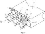
- Figure 5
- is an enlarged perspective view of part of the metal encased storage arrangement in accordance with the present invention.
- Referring to the drawings, in which like numerals indicate like features, a non-limiting example of a hydrogen storage arrangement in accordance with an embodiment of the invention is generally indicated by
reference numeral 10. - The
storage arrangement 10, shown in cross-section inFigure 1 , includes a plurality ofmetal hydride containers 11. Any known layout of metal hydride ("MH") containers with external heating / cooling can be used in the invention, and the invention is therefore not limited to a particular layout of configuration. However, the use of tubular containers that are heated and cooled from the outside is a preferable configuration, as this is the simplest and most cost effective option. - The gas input / output pipelines of the
containers 11 are connected to acommon gas manifold 12 that terminates in anexternal pipeline 13, which enables H2 charging and discharging of thestorage arrangement 10 during absorption or desorption in or out of the MH containers, respectively. - Since H2 absorption in MH is an exothermic process, and H2 desorption is endothermic, the storage arrangement must include heat transfer means 14 for cooling the
MH containers 11 during H2 charging. The storage arrangement also requires means for heating the containers when discharging H2. The maximum efficiency of the cooling and the heating is achieved when the heat transfer means (in the form of heating / cooling means 14) are uniformly distributed in between theMH containers 11 in order to provide approximately the same heat transfer distances to the different containers. Although any kind of the heating / cooling means (heat pipes, electric heaters, thermoelectric modules, etc.) can be used within the scope of the invention, in the preferred embodiment, the heating / cooling means 14 is in the form of a tubing for conveying a heating / cooling fluid (e.g., hot and cold water). The heating / cooling means 14 are in flow communication with asupply conduit 15 and adischarge conduit 16. - The space between the
metal hydride containers 11 and the heating / cooling means 14 is filled with a metal or an alloy which forms afiller body 17 made of a solidified molten metal or alloy, and which closely adjoins the external surfaces of theMH containers 11 and the heating / cooling means 14. Since the metal hydride storage arrangement simultaneously serves as hydrogen storage medium and as a ballast, the metal or alloy should have a high density to provide maximum weight of the storage arrangement at a minimal volume. The metal or alloy also has to have a high thermal conductivity to maximise the rate of the heat exchange between theMH containers 11 and the heating / cooling means 14. - The
filler body 17 envelops all other components of the MH storage arrangement including theMH containers 11, thegas manifold 12 and the heating / cooling means 14. Only the ends, 15 and 16, of theheat transfer conduit 14 and anend 13 of the external pipeline protrudes from thefiller body 17. Although this does not have to be the case, this embodiment is preferred due to a number of reasons including the sealing of possible micro-leaks in the pipelines and their joints during formation of thefiller body 17. However, other embodiments may include configurations where the filler body only partially envelops other components of the MH storage arrangement. When designing the storage arrangement, criteria determining the size of the filling body / degree of the envelopment include: (i) the weight required to be added to the fuel cell power module, (ii) density of the metal or alloy which forms the filler body; and (iii) space available to the hydrogen storage arrangement. All these criteria can be taken into account during the design stage to yield target dimensions of all the components (11-17) of the storage arrangement. - The most effective way of manufacturing the hydrogen storage arrangement schematically shown in
Figure 1 is to fill the space between theMH containers 11 and the heating / cooling means 14 with the molten metal or alloy, followed by its solidification to form the fillingbody 17. Such a procedure is characterised by relatively low labour consumption and costs as compared to alternative ones (e.g., machining of a solid piece of metal to create channels for the MH material and the heating / cooling fluid). It also provides good thermal contact between thefiller body 17, theMH containers 11 and the heating / cooling means 14. The details of the filling procedure will be described below. - The use of the "melting - solidification" process, together with properties of the selected MH material and features of the MH container which can be used in the invention, present some limitations as to the selection of the metal or alloy for the filler body. First of all, the melting / solidification point (MP) of the metal or alloy for making the
filler body 17 must not be higher than the maximum allowed operation temperature of theMH container 11. Among the materials commonly used for the manufacturing solid state hydrogen storage containers, the maximum allowed operation temperature (Tmax=537 °C) is associated with stainless steel. Accordingly, in a preferred embodiment of the invention stainless steel is used as a material to manufacture theMH containers 11. Since any additional joint (gasket, sealed thread coupling, etc.) reduces the temperature rating, the preference is given to the all-welded stainless steel structure. - The maximum allowed operation temperature (Tmax=537 °C in the case of SS) also limits the metals or alloys which are suitable for casting the
filler body 17. For example, copper (MP=1084.6 °C) is not suitable despite its very high thermal conductivity (TC=400 W/(m K)) and relatively high density (8.9 kg/L). The molten copper will end up reducing the strength of the stainless steel containers, which is obviously not desirable. - The inventors have found that one of the most suitable metals for the making the
filler body 17 is lead, which combines a high density (11.3 kg/L) with a not too high melting point (327.5 °C). Thermal conductivity of the lead is modest (35 W/(m K)) but it is similar to the most heat conductive stainless steels (TC=12-45 W/(m K)). Further optimisation of the material for making the filler body within the scope of this invention can be done by using lead alloys with tin (minimum MP=183 °C for the alloy containing 37 wt.% Pb and 63 wt.% Sn; TC increases in ∼1.5 times as compared to pure Pb), cadmium (minimum MP=246 °C at 17 wt.% Cd in Pb), antimony (minimum MP=252 °C at 11 wt.% Sb in Pb), or multicomponent lead-containing alloys, like Cerrosafe (Pb 37.7wt.%, Bi 42.5wt.%, Sn 11.3wt.%, Cd 8.5%wt.%; MP=158-190 °C) or Wood's alloy (Pb 26.7wt. %, Bi 50wt.%, Sn 13.3wt.%,Cd 10%wt.%; MP=70 °C). The use of lead alloys with various compositions therefore allows one to vary the melting / solidification point in relatively wide limits. Apart from the melting point, the selection criteria for the lead alloys for making the filler body include its low cost and reasonably high thermal conductivity. - The melting / solidification point of the metal or alloy for making the
filler body 17 also has to be higher than the activation temperature of the MH material loaded in themetal hydride containers 11. Importantly, the operating temperature of the MH material must be below its activation temperature, and the H2 equilibrium pressure for the MH material at the operating temperature must be higher than the atmospheric pressure to provide H2 supply to a fuel cell stack. - Summarising the above-mentioned, in the preferred embodiment of this invention, the material for making the
filler body 17 is lead or a lead-containing alloy with melting / solidification point between 150 and 350 °C, and the activation temperature of the metal hydride material is between 100 and 300 °C. Most of the commonly used hydrogen storage alloys (e.g. AB5- and AB2-type) satisfy the latter criterion. Moreover, at the temperatures of 50-60 °C (typical operating temperature of low-temperature PEM fuel cell which can be thermally coupled with the MH storage, many of these alloys have a hydrogen equilibrium pressure in excess of 1 bar (100 kPa), which makes them suitable for the use in this invention. - As mentioned above, in the manufacturing of the MH hydrogen storage arrangement in accordance with the present invention entails a procedure of forming the
filler body 17 by the use of "melting - solidification" route. This procedure is crucial, and the method of manufacturing the MH storage arrangement by way of this procedure is described below. - (a) The first step in the manufacturing of the MH storage arrangement entails the assembly of all its components (MH containers, heating / cooling means, gas manifold), except for the filler body, and the placement of such components in a shell or casting mould which, together with the components (MH containers, heating / cooling means, gas manifold), forms a pre-assembly of the metal hydride hydrogen storage arrangement. The MH containers and the heating / cooling means are first installed in their positions in the storage arrangement, followed by the installation of the gas manifold. Leak tests are then performed to test the integrity of the system.
- (b) The pre-assembly, as constructed above, is then located at the place where the casting / filling step will take place. This process requires heating of the assembly to elevated temperatures. Considering that all metal hydride materials are sensitive to a number of gas species (including oxygen and water vapours) that can remain in the inner space of the MH containers or desorb from the surface of the MH material during heating, the inner space of the containers must be evacuated at all times during the manufacturing process in order to avoid a loss or reduction of hydrogen sorption properties of the MH material due to its interaction with the gas species at elevated temperatures. In addition, the evacuation during the heating process will promote the activation of the MH material, so as to enable it to absorb and desorb hydrogen.
Figure 2 shows a schematic diagram of the installation of a pre-assembly of the metal hydride hydrogen storage arrangement for use in manufacturing the hydrogen storage arrangement. The assembly comprises a plurality ofMH containers 11, and heating / cooling means (14-16) placed in-between the containers, with the containers and the hearing / cooling means all being located inside a shell or castingmould 18. Theexternal conduit 13 that extends from thegas manifold 12 is connected to a common port of 3-way valve 31, which provides selective flow communication of the inner space of theMH containers 11 with avacuum pump 32 or agas cylinder 33. The evacuation of the inner space of theMH containers 11 has to be started before proceeding with steps (c) - (e) as described below, and is ceased only when step (e) has been completed. The reason for this is that when thecontainers 11 are at an elevated temperature, even a minor presence of air inside theMH containers 11 can result in the deterioration of the hydrogen sorption properties of the MH material. Moreover, during the steps (c) - (e) below the high temperature of the MH causes intensive desorption of impurities from the surface of the MH material (see example below) which must be removed by way of evacuation. During evacuation, it is recommended for the vacuum to be monitored in a gas system (see example below) that facilitates process control, and in particular, the moment when the evacuation can be ceased. - (c) The complete pre-assembly in the shell /
casting mould 18, including theMH containers 11 and the heating / cooling means 14 require to be heated-up at the next stages of the process (c) - (d). In the preferred embodiment of the invention the assembly is opened at the top, and is heated by way of forced convection from a heater andair blower 25. There is also provided for the pre-assembly to be heated from the bottom by way of auxiliary heating means (not shown), but heating from above is preferable as it provides more uniform heating of the inner elements (11, 14) of the assembly. Theheater 20 can be a conventional gas burner, which has sufficient heating capacity to pre-heat the pre-assembly to the required temperature for a reasonable time. However, the use of a gas burner in isolation can result in the deposition of the products of incomplete combustion (e.g. soot) on the surface of theMH containers 11 and heating / cooling means 14 that can in turn result in poor adhesion of the solidified filler body, which will adversely impact on heat transfer performance. To avoid this, thetop heater 20 can be incorporated into a heating assembly including an air boosting chamber as shown inFigure 3 . Thegas burner 21, in this example supplied with natural gas via agas conduit 22 from agas cylinder 23 is located inside an air-boostingchamber 24 equipped with anair blower 25. The air flow created by theblower 25 will then boost the flame from theburner 21, thus resulting in complete combustion and dilution of combustion products with the air flow. When the rates of gas and air supply are properly adjusted, an intensive stream of hot air will emanate from the exit of the chamber, thus providing effective top heating of the pre-assembly. During step (c), the pre-assembly is pre-heated as described above. The pre-heating temperature depends on the specific embodiment of the invention, and once such temperature is reached, step (d) follows. - (d) Referring again to
Figure 2 , after pre-heating the pre-assembly of the storage arrangement in the shell /mould 18 is filled with a metal or alloy, which will form the filler body of the MH storage arrangement once solidified. The filler can be made in two alternative ways:- i. The metal / alloy is pre-melted and casted into the pre-assembly which has been pre-heated in step (c) to a temperature between 1/2 and 2/3 of the melting point of the metal or the alloy constituting the filler body. This methodology will be particularly suitable for mass production at specialised foundries equipped with the pre-melting and casting facilities. The fact that the maximum pre-heating temperature is below the solidification point of the filler material prevents any potential leakage through gaps which may remain in the
shell 18 resulting from the pre-assembly being a multi-component object. Additionally, with the temperature being below 2/3 of the solidification point, the likelihood of the solidified melt sticking to the shell /mould 18 is significantly reduced. At the same time, the pre-heating temperature higher than 1/2 of the solidification point reduces the likelihood of the premature solidification of the melt. - ii. Alternatively, the metal / alloy can be loaded into the shell /
mould 18, and pre-heated above its melting point while in particulate form. This embodiment requires continuation of the heating process as described in step (c) above. It does not require specialised pre-melting and casting facilities and can provide improved adhesion of the filler material to the surface of theMH containers 11 and the heating / cooling means 14. This will, in turn, result in even better heat transfer between the filler body, the containers, and the heating / cooling means. However, this methodology will entail special care in the manufacturing of the shell /mould 18 to avoid leakage of the molten metal, as well as to prevent the sticking of the solidified filler body to the shell.
- i. The metal / alloy is pre-melted and casted into the pre-assembly which has been pre-heated in step (c) to a temperature between 1/2 and 2/3 of the melting point of the metal or the alloy constituting the filler body. This methodology will be particularly suitable for mass production at specialised foundries equipped with the pre-melting and casting facilities. The fact that the maximum pre-heating temperature is below the solidification point of the filler material prevents any potential leakage through gaps which may remain in the
- (e) After the filler material has been introduced, the molten metal or alloy is allowed to cool down until it is complete solidified. It is important for the temperature to be as low as possible before the evacuation process (which started in step (b)) is interrupted. In practice, the temperature to which the filler body is cooled is a compromise between time and the requirement stated above. As a general rule, the cooling temperature should be below 100 °C. At this temperature, the activation of most of the MH materials which can be used in this invention is completed.
- (f) After the filler body has solidified and cooled down sufficiently, the evacuation is stopped and the inner volume of the
containers 11 is filled with gas. Importantly, this step must take place immediately after the evacuation has been stopped, in order to avoid contamination of the activated MH inside the containers with air which can pass into the containers via micro-leaks. The gas must be pressurised to eliminate the possibility of creating "negative" pressure (below the atmospheric pressure) in the containers while they are cooling down. The recommended sequence of the operations during stage (f) is as follows:- i. Open the
gas cylinder 33; - ii. Switch the 3-
way valve 31 from the evacuation line (from vacuum pump 32) to the gas supply line (from cylinder 33). - iii. Switch the
vacuum pump 32 off.
- i. Open the
- (g) Next, the pre-assembly (filled with the pressurised gas) is allowed to cool down to the room temperature.
- (h) Finally, the metal hydride hydrogen storage arrangement is removed from the shell /
casting mould 18. Importantly, before proceeding with this step thevalve 31 should be switched to a closed position and left connected to the end of thegas pipeline 13 until the final installation of the MH storage arrangement has been completed. - If the gas with which the MH containers are filled during stage (f) is not pure hydrogen, the storage arrangement should also be subjected to the following final activation procedure:
- (a) Release of the pressurised gas from the inner volume of the MH containers via the gas manifold. This can be done by opening the
valve 32 in any position after disconnecting the same from the vacuum and gas supply lines. This should be done before the storage arrangement is removed from the shell / casting during step (f) above. After performing this procedure, the storage arrangement (and more particularly the MH containers) has to be connected to a final activation setup, the piping diagram of which is similar to the gas piping shown inFigure 2 . In this case, one of the free ports of the 3-way valve 31 is connected to thevacuum pump 32, and the other port is connected to ahydrogen cylinder 33. - (b) The storage containers are subsequently evacuated using the
vacuum pump 32. - (c) Finally, the storage containers are filled with pressurised hydrogen from the
cylinder 33 after thevalve 31 has been switched from thevacuum pump 32 to thecylinder 33. - The MH storage arrangement and the method of manufacturing thereof as described above can be made as a single unit ready for integration into a utility vehicle. Alternatively, the storage arrangement can be made up of an assembly of several smaller modules made as described above. This option adds flexibility in making MH hydrogen storage arrangements for various utility vehicles based on a unified modular design that is beneficial for mass production.
- The following example illustrates one of numerous embodiments of the present invention.
- According to the design specification of a 15 kWe fuel cell power module for a 3.5 tonnes STILL electric forklift, a metal hydride hydrogen storage arrangement should:
- provide hydrogen storage capacity of 20 Nm3 H2;
- have a weight between 1 and 1.5 tonnes;
- occupy a volume not higher than 200 L; and
- not be longer than 1 m.
- For the hydrogen storage arrangement, it was suggested to use 40 tubular metal hydride containers made as all-welded stainless steel structures, which will in use be filled with an AB2-type hydrogen storage alloy characterised by a hydrogen equilibrium pressure of about 10 bar at room temperature and an activation temperature of between 150 and 300 °C. Each container is 51.3 mm in diameter, 800 mm in length, 8.9 kg in weight (incl. MH material) and has a hydrogen storage capacity of about 0.5 Nm3.
- The assembly of the 40 MH containers staggered into a 200L volume will have a weight of 356 kg. Had the empty space between containers been filled with water (as per one of the prior art configurations), the total weight of the hydrogen storage arrangement would have amounted to about 490 kg, which is far below the lower weight constraint of the application.
- In order to adhere to the specification requirements, a metal hydride hydrogen storage arrangement according to the present invention has been designed. The storage arrangement is an assembly of 8 modules (MH cassettes) each comprising of 5 MH containers as described above. A 15 mm OD stainless steel heating / cooling pipe extends between the cassettes and the empty space is occupied by a filler body made of lead. The total storage arrangement dimensions (8 cassettes packed together) are 704 mm (L) x 960 mm (W) x 264 mm (H) that corresponds to the total volume below 170L. The target weight of one cassette was calculated to be between 125 and 187.5 kg, with the combined weight therefore exceeding the 1 ton requirement.
-
Figure 4 shows a pre-assembly of the MH cassette prepared for the casting of the lead filler body. TheMH containers 11, together with the heating /cooling pipe 14, are pre-assembled in aremovable shell 18 made of stainless steel sheets, and which envelopes the MH containers and the pipes with the exception of thegas manifold 12 and the welded joints between the coolingpipes 14. The total weight of the cassette / pre-assembly before casting of the lead filler body was about 45 kg. The gaps in the shell were sealed by a high-temperature sealant to avoid spillage of the molten lead during the manufacturing process. -
Figure 4 also shows some other accessories used when filling the pre-assembly with lead, including a top heater as discussed above. The pre-assembly was located on a support, and exposed to two auxiliary bottom gas burners which provided some auxiliary heating. - Before depositing the lead filler, the assembly was evacuated. After achieving a vacuum of about 10-2 mbar, the assembly was pre-heated up to about 170 °C (temperature measurement by a K-type thermocouple built into cassette, also assisted by optical pyrometer). The pre-melted lead (T∼350 °C) was then casted into the pre-assembly. During pre-heating (20 min) and casting the molten lead (30 min) the pressure in the evacuated system increased to 2 mbar followed by the gradual decrease to 0.1 mbar before the end of the casting step.
- After finishing the lead casting, the heaters were switched off, and the lead-filled cassette was allowed to cool down to a temperature of about 90 °C, at which point the vacuum was in excess of 5·10-2 mbar. The cassette was then filled with pressurised argon at a pressure of about 50 bar.
- After cooling the lead encased and argon-filled cassette to room temperature, the stainless steel sheets making up the
shell 18 were removed, and the module of the metal hydride hydrogen storage arrangement (960x269x88 mm; weight 144 kg) was connected to a final activation setup. During final activation, the argon was first released, and the containers where then again evacuated to about 3·10-2 mbar. Hydrogen at a supply pressure of about 50 bar was then supplied to thegas manifold 12. Hydrogen absorption in the MH started immediately, as was evident from the gradual increase of the temperature of the storage arrangement measured by a built-in K-type thermocouple 19. The hydrogen was introduced at maximum H2 flow, which in this case was 40 NL/min (upper limit set by mass flow controller due to necessity to be within its measurement range). The H2 flow of 40 NL/min remained unchanged during 40 minutes followed by a gradual decrease in flowrate when the temperature reached about 60 °C (increased from an initial temperature of 25 °C). After the cooling of the storage arrangement commenced (using water at a temperature of about 20 °C and a flow rate of about 5 L/min), the flow of the absorbed H2 (40 NL/min) increased again, and remained constant for a further 10 min followed by a gradual decrease. The total amount of hydrogen absorbed in the storage arrangement during 100 minutes (until the H2 flow rate decreased below 4 NL/min) was of 2591 NL (calculated by the integration of time dependence of the flow rate). This was more than the specification requirement (2500 NL). - The example presented above demonstrates the workability of the engineering solution described in the present invention even in the case where the best possible embodiment could not be used (due to the incomplete encapsulation of the storage arrangement components within the filler body, use of argon instead of hydrogen to fill the inner volume of the MH containers after its solidification, and the modest heat conductivity of the metal used).
- The inventors foresee that the practical application of the invention can be further improved by the optimisation of the composition of the alloy forming the filler body (increase of the thermal conductivity without a significant decrease of the density and increase in the cost), and the improvement of the design of the storage arrangement and the auxiliary accessories (casting mould, top heater), etc.
- The present invention offers a design and a method of manufacturing a compact hydrogen storage arrangement which will be useful in a number of fuel cell powered heavy duty vehicles including material handling units, mining locomotives, and marine applications. The use of the invention will also result in the reduction or elimination of space occupied by ballast in these kind of vehicles, thus adding flexibility to the layout of other components (stack + BoP) of the fuel cell power modules which can in turn be improved in terms of ease of assembly and service.
- The solution of the problem of the increase of space available for the placement of a fuel cell and its BoP within weight and space constrains of a utility vehicle resides in "merging" the ballast and the metal hydride hydrogen storage system in an integrated design resulting in a unified hydrogen storage arrangement. The invention is inventive, in that it departs from the conventional design methodology of MH storage systems, in which the aim is to reduce the weight of the fuel storage arrangements. At the same time, the integrated system will also provide efficient heating and cooling of the MH material to provide sufficient rates of H2 desorption / absorption during the H2 discharge / charge. Finally, the procedure of making the MH hydrogen storage arrangement has to be simple, cost-efficient, safe and reliable - including the elimination of a possibility of deterioration of hydrogen sorption properties of the MH material during the manufacturing of the storage arrangement. The present invention meets all these criteria.
Claims (12)
- A metal hydride hydrogen storage arrangement suitable for use in a fuel cell utility vehicle, the storage arrangement including:a plurality of metal hydride containers suitable to be filled with a metal hydride material, the containers being connectable in parallel to a gas manifold;heat transfer means located between the metal hydride containers; anda filler body located in a space between the metal hydride containers and the heat transfer means.
- The metal hydride hydrogen storage arrangement of claim 1 in which the filler body is located in close proximity of external surfaces of the containers and the heat transfer means.
- The metal hydride hydrogen storage arrangement of claim 1 or 2 in which the filler body is in the form of a metal body formed by the melting and solidification of a metal or an alloy in the space between the metal hydride containers and the heat transfer means.
- The metal hydride hydrogen storage arrangement of claim 3 in which the metal or the alloy has a melting / solidification point below the maximum allowed operation temperature of the metal hydride container, but above the activation temperature of the metal hydride material inside the metal hydride container.
- The metal hydride hydrogen storage arrangement of claim 4 in which the metal or the alloy which forms the filling body is a lead or a lead-containing alloy with a melting point between 150 and 350 °C.
- A method of manufacturing a metal hydride hydrogen storage arrangement suitable for use in a fuel cell utility vehicle, the method including the steps of:- locating a plurality of metal hydride containers and heat transfer means inside a casting mould to form a pre-assembly;- evacuating an inner space of the containers; and- filling a space between the containers and the heat transfer means with a filler material; and- removing the casting mould.
- The method of claim 6 in which the step of filling the space between the containers and the heat transfer means with a filler material to include the steps of:- pre-heating the pre-assembly;- filling the space between the containers and the heat transfer means with the filler material;- cooling the pre-assembly filled with the filler material to a temperature below the melting / solidification point;- filling the inner volume of the metal hydride containers via the gas manifold with a pressurised gas; and- cooling the pre-assembly filled with the solidified filler material and the pressurised gas to room temperature.
- The method of claim 7 in which the pre-assembly of the metal hydride hydrogen storage arrangement may be open at the top, and wherein the pre-heating step is carried out by directing a flow of hot air onto the top of the pre-assembly.
- The method of claim 7 or claim 8 wherein the step of pre-heating the pre-assembly is continued until reaching a temperature of between a half and two thirds of the melting point of the metal or the alloy which forms the filler body.
- The method of claim 7, 8 or 9 wherein the pressurised gas is hydrogen, an inert gas, or a mixture of hydrogen and an inert gas.
- The method of any one of claims 7 to 9 in which the pressurised gas is not hydrogen, the method in this instance including a final activation procedure which includes the steps of:- releasing the pressurised gas from the inner volume of the containers via the gas manifold;- evacuating the inner volume of the containers via the gas manifold; and- filling the inner volume of the containers with pressurised hydrogen via the gas manifold.
- A metal hydride hydrogen storage arrangement including a plurality of storage arrangements as described in claims 1 to 5.
Applications Claiming Priority (1)
| Application Number | Priority Date | Filing Date | Title |
|---|---|---|---|
| GBGB1806840.3A GB201806840D0 (en) | 2018-04-26 | 2018-04-26 | Metal hydride hydrogen storage arrangement for use in a fuel cell utility vehicle and method of manufacturing the same |
Publications (2)
| Publication Number | Publication Date |
|---|---|
| EP3567664A1 true EP3567664A1 (en) | 2019-11-13 |
| EP3567664B1 EP3567664B1 (en) | 2022-12-07 |
Family
ID=62495161
Family Applications (1)
| Application Number | Title | Priority Date | Filing Date |
|---|---|---|---|
| EP19170287.7A Active EP3567664B1 (en) | 2018-04-26 | 2019-04-18 | Metal hydride hydrogen storage arrangement for use in a fuel cell utility vehicle and method of manufacturing the same |
Country Status (4)
| Country | Link |
|---|---|
| US (1) | US11611092B2 (en) |
| EP (1) | EP3567664B1 (en) |
| GB (1) | GB201806840D0 (en) |
| ZA (1) | ZA201901418B (en) |
Families Citing this family (6)
| Publication number | Priority date | Publication date | Assignee | Title |
|---|---|---|---|---|
| JP7568225B2 (en) | 2021-01-07 | 2024-10-16 | 清水建設株式会社 | Heat medium supply system and heat medium supply method |
| EP4141315A1 (en) * | 2021-08-23 | 2023-03-01 | GRZ Technologies SA | Hydrogen storage-compression system |
| CN117836553A (en) * | 2021-08-27 | 2024-04-05 | 川崎重工业株式会社 | Hydrogen delivery system |
| US20230076613A1 (en) * | 2021-09-02 | 2023-03-09 | Herve-David Gregoire-Mazzocco | Systems and methods for hydrogen energy and energy aggregation |
| KR20230089605A (en) * | 2021-12-13 | 2023-06-21 | 삼성전자주식회사 | Heat exchanger and heat exchanging system comprising the same |
| GB202408072D0 (en) | 2024-06-06 | 2024-07-24 | Univ Of The Western Cape | Fuel cell vehicle and a power module for use in the fuel cell vehicle |
Citations (12)
| Publication number | Priority date | Publication date | Assignee | Title |
|---|---|---|---|---|
| US1159865A (en) * | 1914-05-07 | 1915-11-09 | Mathias Pier | Apparatus for effecting reactions of hydrogen under pressure. |
| GB2135901A (en) * | 1983-02-28 | 1984-09-12 | Hydrocarbon Research Inc | Multilayer pressure vessel construction and use |
| JPS62197265A (en) * | 1986-02-21 | 1987-08-31 | Kawasaki Steel Corp | Building-up method for insoluble electrode for electroplating |
| JPH08250140A (en) * | 1995-03-08 | 1996-09-27 | Sanyo Electric Co Ltd | Drying device and drying method for hydrogen storage alloy tank |
| US20030215684A1 (en) * | 2002-05-17 | 2003-11-20 | Asia Pacific Fuel Cell Technologies, Ltd. | Heating device for hydrogen storage canister |
| US20040139761A1 (en) * | 2000-06-27 | 2004-07-22 | Shinya Hiramatsu | Cooling unit and manufacturing method of the same |
| US20040142291A1 (en) * | 2003-01-21 | 2004-07-22 | Yang Jefferson Ys | Device and method for heating hydrogen storage canister |
| US20090035623A1 (en) * | 2004-07-26 | 2009-02-05 | Nobuyoshi Tsuji | Functional product, treatment device of functional substance, applied device of functional product and mounting method of functional product |
| KR20110005754A (en) * | 2009-07-11 | 2011-01-19 | 황성조 | Fuel cell forklift |
| US8636834B2 (en) * | 2008-12-16 | 2014-01-28 | Centre National De La Recherche Scientifique | Adiabatic tank for metal hydride |
| US20140137562A1 (en) * | 2012-11-19 | 2014-05-22 | Eveready Battery Company, Inc. | Hydrogen Generator Having a Thermal Actuator |
| US20160129417A1 (en) * | 2014-11-11 | 2016-05-12 | Paul R. Aimone | Microreactor systems and methods |
Family Cites Families (8)
| Publication number | Priority date | Publication date | Assignee | Title |
|---|---|---|---|---|
| US5092281A (en) | 1988-07-26 | 1992-03-03 | Kabushiki Kaisha Toyoda Jidoshokki Seisakusho | Hydrogen engine system |
| US5445099A (en) | 1993-09-20 | 1995-08-29 | Rendina; David D. | Hydrogen hydride keel |
| US5673939A (en) * | 1995-09-20 | 1997-10-07 | The Babcock & Wilcox Company | Fuel tank for storing and dispensing hydrogen and oxygen gas to a fuel cell |
| DE10063174A1 (en) | 2000-12-18 | 2002-06-20 | Still Gmbh | Industrial truck with a hydrogen storage |
| US20060065553A1 (en) * | 2004-09-27 | 2006-03-30 | Golben P M | Flexible hydrogen delivery mechanism for storage and recovery of hydrogen |
| DE102007054246A1 (en) * | 2007-11-14 | 2009-05-20 | Daimler Ag | Fuel cell drive for a motor vehicle |
| CA2648519A1 (en) | 2007-12-28 | 2009-06-28 | The Raymond Corporation | Material handling vehicle including integrated hydrogen storage |
| KR20120042713A (en) * | 2009-02-04 | 2012-05-03 | 퍼듀 리서치 파운데이션 | Coiled and microchannel heat exchangers for metal hydride storage systems |
-
2018
- 2018-04-26 GB GBGB1806840.3A patent/GB201806840D0/en not_active Ceased
-
2019
- 2019-03-07 ZA ZA2019/01418A patent/ZA201901418B/en unknown
- 2019-04-18 US US16/387,617 patent/US11611092B2/en active Active
- 2019-04-18 EP EP19170287.7A patent/EP3567664B1/en active Active
Patent Citations (12)
| Publication number | Priority date | Publication date | Assignee | Title |
|---|---|---|---|---|
| US1159865A (en) * | 1914-05-07 | 1915-11-09 | Mathias Pier | Apparatus for effecting reactions of hydrogen under pressure. |
| GB2135901A (en) * | 1983-02-28 | 1984-09-12 | Hydrocarbon Research Inc | Multilayer pressure vessel construction and use |
| JPS62197265A (en) * | 1986-02-21 | 1987-08-31 | Kawasaki Steel Corp | Building-up method for insoluble electrode for electroplating |
| JPH08250140A (en) * | 1995-03-08 | 1996-09-27 | Sanyo Electric Co Ltd | Drying device and drying method for hydrogen storage alloy tank |
| US20040139761A1 (en) * | 2000-06-27 | 2004-07-22 | Shinya Hiramatsu | Cooling unit and manufacturing method of the same |
| US20030215684A1 (en) * | 2002-05-17 | 2003-11-20 | Asia Pacific Fuel Cell Technologies, Ltd. | Heating device for hydrogen storage canister |
| US20040142291A1 (en) * | 2003-01-21 | 2004-07-22 | Yang Jefferson Ys | Device and method for heating hydrogen storage canister |
| US20090035623A1 (en) * | 2004-07-26 | 2009-02-05 | Nobuyoshi Tsuji | Functional product, treatment device of functional substance, applied device of functional product and mounting method of functional product |
| US8636834B2 (en) * | 2008-12-16 | 2014-01-28 | Centre National De La Recherche Scientifique | Adiabatic tank for metal hydride |
| KR20110005754A (en) * | 2009-07-11 | 2011-01-19 | 황성조 | Fuel cell forklift |
| US20140137562A1 (en) * | 2012-11-19 | 2014-05-22 | Eveready Battery Company, Inc. | Hydrogen Generator Having a Thermal Actuator |
| US20160129417A1 (en) * | 2014-11-11 | 2016-05-12 | Paul R. Aimone | Microreactor systems and methods |
Also Published As
| Publication number | Publication date |
|---|---|
| EP3567664B1 (en) | 2022-12-07 |
| ZA201901418B (en) | 2022-09-28 |
| US11611092B2 (en) | 2023-03-21 |
| GB201806840D0 (en) | 2018-06-13 |
| US20190334185A1 (en) | 2019-10-31 |
Similar Documents
| Publication | Publication Date | Title |
|---|---|---|
| US11611092B2 (en) | Metal hydride hydrogen storage arrangement for use in a fuel cell utility vehicle and method of manufacturing the same | |
| CN103185196B (en) | A kind of metal hydride storage system and preparation method thereof | |
| EP0995944B1 (en) | Process for filling hydrogen into a hydrogen storage car tank | |
| FR2508596A1 (en) | CONTAINER FOR PRESSURIZED GASES, IN PARTICULAR FOR THE STORAGE OF HYDROGEN | |
| CN114413171A (en) | High pressure vessel | |
| EP3469286A1 (en) | Heat exchanger-accumulator | |
| CN110165327B (en) | A battery pack heat treatment device and a manufacturing method of a phase change material | |
| CN110635086A (en) | A battery pack anti-overheating anti-spontaneous combustion anti-explosion method | |
| US10511039B2 (en) | Solid state hydrogen storage device and solid state hydrogen storage system | |
| CN110544784B (en) | Fuel cell logistics vehicle with high-pressure composite metal hydride hydrogen storage system as hydrogen source | |
| CN101347836A (en) | Vacuum induction melting furnace | |
| CN112410572A (en) | A melting and purification device for liquid metal circuit | |
| CN201283426Y (en) | Vacuum induction smelting furnace | |
| CN117028825A (en) | A hybrid hydrogen storage system and method | |
| WO2025166898A1 (en) | Battery, and electrical apparatus having same | |
| CN113236969A (en) | Electrical heating type metal hydrogen storage and release system | |
| CN115962572B (en) | Fused salt storage container, fused salt heat management system and fused salt heat management method | |
| FR2824755A1 (en) | Modular reactor for an exothermic reaction with reaction and heat-extracting plates alternating in a sandwich, with channels for catalyst and reaction, and for exchange fluid respectively | |
| WO2010147674A2 (en) | A solar energy storage and collection system | |
| CN119419406A (en) | A battery pack liquid cooling plate flow channel structure with fire protection and method thereof | |
| CN118935241A (en) | Solid-state hydrogen storage and degassing container and system for forced circulation heat exchange hydrogen filling and electric heating hydrogen degassing | |
| CN118336025A (en) | Magnesium-based normal temperature solid-state composite hydrogen storage and supply device and application method thereof | |
| CN211695843U (en) | Chain melting furnace of two operation modes | |
| CN210429935U (en) | Battery package anti-overheating spontaneous combustion prevention and self-explosion prevention system | |
| US20250062438A1 (en) | Heat exchanger plate for battery pack |
Legal Events
| Date | Code | Title | Description |
|---|---|---|---|
| PUAI | Public reference made under article 153(3) epc to a published international application that has entered the european phase |
Free format text: ORIGINAL CODE: 0009012 |
|
| STAA | Information on the status of an ep patent application or granted ep patent |
Free format text: STATUS: REQUEST FOR EXAMINATION WAS MADE |
|
| 17P | Request for examination filed |
Effective date: 20190418 |
|
| AK | Designated contracting states |
Kind code of ref document: A1 Designated state(s): AL AT BE BG CH CY CZ DE DK EE ES FI FR GB GR HR HU IE IS IT LI LT LU LV MC MK MT NL NO PL PT RO RS SE SI SK SM TR |
|
| AX | Request for extension of the european patent |
Extension state: BA ME |
|
| RBV | Designated contracting states (corrected) |
Designated state(s): AL AT BE BG CH CY CZ DE DK EE ES FI FR GB GR HR HU IE IS IT LI LT LU LV MC MK MT NL NO PL PT RO RS SE SI SK SM TR |
|
| REG | Reference to a national code |
Ref country code: DE Ref legal event code: R079 Ref document number: 602019022773 Country of ref document: DE Free format text: PREVIOUS MAIN CLASS: H01M0008065000 Ipc: C01B0003000000 |
|
| RIC1 | Information provided on ipc code assigned before grant |
Ipc: F28F 7/02 20060101ALN20220527BHEP Ipc: B60K 15/03 20060101ALI20220527BHEP Ipc: F17C 11/00 20060101ALI20220527BHEP Ipc: H01M 8/065 20160101ALI20220527BHEP Ipc: C01B 3/00 20060101AFI20220527BHEP |
|
| RIC1 | Information provided on ipc code assigned before grant |
Ipc: F28F 7/02 20060101ALN20220630BHEP Ipc: F17C 11/00 20060101ALI20220630BHEP Ipc: H01M 8/065 20160101ALI20220630BHEP Ipc: C01B 3/00 20060101AFI20220630BHEP |
|
| GRAP | Despatch of communication of intention to grant a patent |
Free format text: ORIGINAL CODE: EPIDOSNIGR1 |
|
| STAA | Information on the status of an ep patent application or granted ep patent |
Free format text: STATUS: GRANT OF PATENT IS INTENDED |
|
| INTG | Intention to grant announced |
Effective date: 20220905 |
|
| GRAS | Grant fee paid |
Free format text: ORIGINAL CODE: EPIDOSNIGR3 |
|
| GRAA | (expected) grant |
Free format text: ORIGINAL CODE: 0009210 |
|
| STAA | Information on the status of an ep patent application or granted ep patent |
Free format text: STATUS: THE PATENT HAS BEEN GRANTED |
|
| RIN1 | Information on inventor provided before grant (corrected) |
Inventor name: PARSONS, ADRIAN J Inventor name: DAVIDS, MOEGAMAT WAFEEQ Inventor name: TOLJ, IVAN Inventor name: KLOCHKO, YEVGENIY Inventor name: LOTOTSKYY, MYKHAYLO VOLODYMYROVICH |
|
| AK | Designated contracting states |
Kind code of ref document: B1 Designated state(s): AL AT BE BG CH CY CZ DE DK EE ES FI FR GB GR HR HU IE IS IT LI LT LU LV MC MK MT NL NO PL PT RO RS SE SI SK SM TR |
|
| REG | Reference to a national code |
Ref country code: GB Ref legal event code: FG4D |
|
| REG | Reference to a national code |
Ref country code: CH Ref legal event code: EP Ref country code: AT Ref legal event code: REF Ref document number: 1536220 Country of ref document: AT Kind code of ref document: T Effective date: 20221215 |
|
| REG | Reference to a national code |
Ref country code: DE Ref legal event code: R096 Ref document number: 602019022773 Country of ref document: DE |
|
| REG | Reference to a national code |
Ref country code: IE Ref legal event code: FG4D |
|
| REG | Reference to a national code |
Ref country code: LT Ref legal event code: MG9D |
|
| REG | Reference to a national code |
Ref country code: NL Ref legal event code: MP Effective date: 20221207 |
|
| PG25 | Lapsed in a contracting state [announced via postgrant information from national office to epo] |
Ref country code: SE Free format text: LAPSE BECAUSE OF FAILURE TO SUBMIT A TRANSLATION OF THE DESCRIPTION OR TO PAY THE FEE WITHIN THE PRESCRIBED TIME-LIMIT Effective date: 20221207 Ref country code: NO Free format text: LAPSE BECAUSE OF FAILURE TO SUBMIT A TRANSLATION OF THE DESCRIPTION OR TO PAY THE FEE WITHIN THE PRESCRIBED TIME-LIMIT Effective date: 20230307 Ref country code: LT Free format text: LAPSE BECAUSE OF FAILURE TO SUBMIT A TRANSLATION OF THE DESCRIPTION OR TO PAY THE FEE WITHIN THE PRESCRIBED TIME-LIMIT Effective date: 20221207 Ref country code: FI Free format text: LAPSE BECAUSE OF FAILURE TO SUBMIT A TRANSLATION OF THE DESCRIPTION OR TO PAY THE FEE WITHIN THE PRESCRIBED TIME-LIMIT Effective date: 20221207 Ref country code: ES Free format text: LAPSE BECAUSE OF FAILURE TO SUBMIT A TRANSLATION OF THE DESCRIPTION OR TO PAY THE FEE WITHIN THE PRESCRIBED TIME-LIMIT Effective date: 20221207 |
|
| REG | Reference to a national code |
Ref country code: AT Ref legal event code: MK05 Ref document number: 1536220 Country of ref document: AT Kind code of ref document: T Effective date: 20221207 |
|
| PG25 | Lapsed in a contracting state [announced via postgrant information from national office to epo] |
Ref country code: RS Free format text: LAPSE BECAUSE OF FAILURE TO SUBMIT A TRANSLATION OF THE DESCRIPTION OR TO PAY THE FEE WITHIN THE PRESCRIBED TIME-LIMIT Effective date: 20221207 Ref country code: PL Free format text: LAPSE BECAUSE OF FAILURE TO SUBMIT A TRANSLATION OF THE DESCRIPTION OR TO PAY THE FEE WITHIN THE PRESCRIBED TIME-LIMIT Effective date: 20221207 Ref country code: LV Free format text: LAPSE BECAUSE OF FAILURE TO SUBMIT A TRANSLATION OF THE DESCRIPTION OR TO PAY THE FEE WITHIN THE PRESCRIBED TIME-LIMIT Effective date: 20221207 Ref country code: HR Free format text: LAPSE BECAUSE OF FAILURE TO SUBMIT A TRANSLATION OF THE DESCRIPTION OR TO PAY THE FEE WITHIN THE PRESCRIBED TIME-LIMIT Effective date: 20221207 Ref country code: GR Free format text: LAPSE BECAUSE OF FAILURE TO SUBMIT A TRANSLATION OF THE DESCRIPTION OR TO PAY THE FEE WITHIN THE PRESCRIBED TIME-LIMIT Effective date: 20230308 |
|
| P01 | Opt-out of the competence of the unified patent court (upc) registered |
Effective date: 20230510 |
|
| PG25 | Lapsed in a contracting state [announced via postgrant information from national office to epo] |
Ref country code: NL Free format text: LAPSE BECAUSE OF FAILURE TO SUBMIT A TRANSLATION OF THE DESCRIPTION OR TO PAY THE FEE WITHIN THE PRESCRIBED TIME-LIMIT Effective date: 20221207 |
|
| PG25 | Lapsed in a contracting state [announced via postgrant information from national office to epo] |
Ref country code: SM Free format text: LAPSE BECAUSE OF FAILURE TO SUBMIT A TRANSLATION OF THE DESCRIPTION OR TO PAY THE FEE WITHIN THE PRESCRIBED TIME-LIMIT Effective date: 20221207 Ref country code: RO Free format text: LAPSE BECAUSE OF FAILURE TO SUBMIT A TRANSLATION OF THE DESCRIPTION OR TO PAY THE FEE WITHIN THE PRESCRIBED TIME-LIMIT Effective date: 20221207 Ref country code: PT Free format text: LAPSE BECAUSE OF FAILURE TO SUBMIT A TRANSLATION OF THE DESCRIPTION OR TO PAY THE FEE WITHIN THE PRESCRIBED TIME-LIMIT Effective date: 20230410 Ref country code: EE Free format text: LAPSE BECAUSE OF FAILURE TO SUBMIT A TRANSLATION OF THE DESCRIPTION OR TO PAY THE FEE WITHIN THE PRESCRIBED TIME-LIMIT Effective date: 20221207 Ref country code: CZ Free format text: LAPSE BECAUSE OF FAILURE TO SUBMIT A TRANSLATION OF THE DESCRIPTION OR TO PAY THE FEE WITHIN THE PRESCRIBED TIME-LIMIT Effective date: 20221207 Ref country code: AT Free format text: LAPSE BECAUSE OF FAILURE TO SUBMIT A TRANSLATION OF THE DESCRIPTION OR TO PAY THE FEE WITHIN THE PRESCRIBED TIME-LIMIT Effective date: 20221207 |
|
| PG25 | Lapsed in a contracting state [announced via postgrant information from national office to epo] |
Ref country code: SK Free format text: LAPSE BECAUSE OF FAILURE TO SUBMIT A TRANSLATION OF THE DESCRIPTION OR TO PAY THE FEE WITHIN THE PRESCRIBED TIME-LIMIT Effective date: 20221207 Ref country code: IS Free format text: LAPSE BECAUSE OF FAILURE TO SUBMIT A TRANSLATION OF THE DESCRIPTION OR TO PAY THE FEE WITHIN THE PRESCRIBED TIME-LIMIT Effective date: 20230407 Ref country code: AL Free format text: LAPSE BECAUSE OF FAILURE TO SUBMIT A TRANSLATION OF THE DESCRIPTION OR TO PAY THE FEE WITHIN THE PRESCRIBED TIME-LIMIT Effective date: 20221207 |
|
| REG | Reference to a national code |
Ref country code: DE Ref legal event code: R097 Ref document number: 602019022773 Country of ref document: DE |
|
| PLBE | No opposition filed within time limit |
Free format text: ORIGINAL CODE: 0009261 |
|
| STAA | Information on the status of an ep patent application or granted ep patent |
Free format text: STATUS: NO OPPOSITION FILED WITHIN TIME LIMIT |
|
| PG25 | Lapsed in a contracting state [announced via postgrant information from national office to epo] |
Ref country code: DK Free format text: LAPSE BECAUSE OF FAILURE TO SUBMIT A TRANSLATION OF THE DESCRIPTION OR TO PAY THE FEE WITHIN THE PRESCRIBED TIME-LIMIT Effective date: 20221207 |
|
| 26N | No opposition filed |
Effective date: 20230908 |
|
| PG25 | Lapsed in a contracting state [announced via postgrant information from national office to epo] |
Ref country code: SI Free format text: LAPSE BECAUSE OF FAILURE TO SUBMIT A TRANSLATION OF THE DESCRIPTION OR TO PAY THE FEE WITHIN THE PRESCRIBED TIME-LIMIT Effective date: 20221207 |
|
| REG | Reference to a national code |
Ref country code: CH Ref legal event code: PL |
|
| GBPC | Gb: european patent ceased through non-payment of renewal fee |
Effective date: 20230418 |
|
| PG25 | Lapsed in a contracting state [announced via postgrant information from national office to epo] |
Ref country code: LU Free format text: LAPSE BECAUSE OF NON-PAYMENT OF DUE FEES Effective date: 20230418 |
|
| REG | Reference to a national code |
Ref country code: BE Ref legal event code: MM Effective date: 20230430 |
|
| PG25 | Lapsed in a contracting state [announced via postgrant information from national office to epo] |
Ref country code: MC Free format text: LAPSE BECAUSE OF FAILURE TO SUBMIT A TRANSLATION OF THE DESCRIPTION OR TO PAY THE FEE WITHIN THE PRESCRIBED TIME-LIMIT Effective date: 20221207 |
|
| PG25 | Lapsed in a contracting state [announced via postgrant information from national office to epo] |
Ref country code: GB Free format text: LAPSE BECAUSE OF NON-PAYMENT OF DUE FEES Effective date: 20230418 |
|
| PG25 | Lapsed in a contracting state [announced via postgrant information from national office to epo] |
Ref country code: MC Free format text: LAPSE BECAUSE OF FAILURE TO SUBMIT A TRANSLATION OF THE DESCRIPTION OR TO PAY THE FEE WITHIN THE PRESCRIBED TIME-LIMIT Effective date: 20221207 Ref country code: LI Free format text: LAPSE BECAUSE OF NON-PAYMENT OF DUE FEES Effective date: 20230430 Ref country code: GB Free format text: LAPSE BECAUSE OF NON-PAYMENT OF DUE FEES Effective date: 20230418 Ref country code: CH Free format text: LAPSE BECAUSE OF NON-PAYMENT OF DUE FEES Effective date: 20230430 |
|
| REG | Reference to a national code |
Ref country code: IE Ref legal event code: MM4A |
|
| PG25 | Lapsed in a contracting state [announced via postgrant information from national office to epo] |
Ref country code: BE Free format text: LAPSE BECAUSE OF NON-PAYMENT OF DUE FEES Effective date: 20230430 |
|
| PG25 | Lapsed in a contracting state [announced via postgrant information from national office to epo] |
Ref country code: IE Free format text: LAPSE BECAUSE OF NON-PAYMENT OF DUE FEES Effective date: 20230418 |
|
| PG25 | Lapsed in a contracting state [announced via postgrant information from national office to epo] |
Ref country code: IE Free format text: LAPSE BECAUSE OF NON-PAYMENT OF DUE FEES Effective date: 20230418 |
|
| PG25 | Lapsed in a contracting state [announced via postgrant information from national office to epo] |
Ref country code: BG Free format text: LAPSE BECAUSE OF FAILURE TO SUBMIT A TRANSLATION OF THE DESCRIPTION OR TO PAY THE FEE WITHIN THE PRESCRIBED TIME-LIMIT Effective date: 20221207 |
|
| PG25 | Lapsed in a contracting state [announced via postgrant information from national office to epo] |
Ref country code: BG Free format text: LAPSE BECAUSE OF FAILURE TO SUBMIT A TRANSLATION OF THE DESCRIPTION OR TO PAY THE FEE WITHIN THE PRESCRIBED TIME-LIMIT Effective date: 20221207 |
|
| REG | Reference to a national code |
Ref country code: DE Ref legal event code: R082 Ref document number: 602019022773 Country of ref document: DE Representative=s name: PLASSERAUD IP GMBH, DE |
|
| PGFP | Annual fee paid to national office [announced via postgrant information from national office to epo] |
Ref country code: DE Payment date: 20250218 Year of fee payment: 7 |
|
| PG25 | Lapsed in a contracting state [announced via postgrant information from national office to epo] |
Ref country code: CY Free format text: LAPSE BECAUSE OF FAILURE TO SUBMIT A TRANSLATION OF THE DESCRIPTION OR TO PAY THE FEE WITHIN THE PRESCRIBED TIME-LIMIT; INVALID AB INITIO Effective date: 20190418 |
|
| PG25 | Lapsed in a contracting state [announced via postgrant information from national office to epo] |
Ref country code: HU Free format text: LAPSE BECAUSE OF FAILURE TO SUBMIT A TRANSLATION OF THE DESCRIPTION OR TO PAY THE FEE WITHIN THE PRESCRIBED TIME-LIMIT; INVALID AB INITIO Effective date: 20190418 |
|
| PG25 | Lapsed in a contracting state [announced via postgrant information from national office to epo] |
Ref country code: TR Free format text: LAPSE BECAUSE OF FAILURE TO SUBMIT A TRANSLATION OF THE DESCRIPTION OR TO PAY THE FEE WITHIN THE PRESCRIBED TIME-LIMIT Effective date: 20221207 |
|
| PGFP | Annual fee paid to national office [announced via postgrant information from national office to epo] |
Ref country code: IT Payment date: 20260320 Year of fee payment: 8 |
|
| PGFP | Annual fee paid to national office [announced via postgrant information from national office to epo] |
Ref country code: FR Payment date: 20260223 Year of fee payment: 8 |