EP3567624A1 - Bus bar - Google Patents
Bus bar Download PDFInfo
- Publication number
- EP3567624A1 EP3567624A1 EP18171061.7A EP18171061A EP3567624A1 EP 3567624 A1 EP3567624 A1 EP 3567624A1 EP 18171061 A EP18171061 A EP 18171061A EP 3567624 A1 EP3567624 A1 EP 3567624A1
- Authority
- EP
- European Patent Office
- Prior art keywords
- bus bar
- rigid
- fuse
- web
- housing
- Prior art date
- Legal status (The legal status is an assumption and is not a legal conclusion. Google has not performed a legal analysis and makes no representation as to the accuracy of the status listed.)
- Withdrawn
Links
- 239000000463 material Substances 0.000 claims description 3
- 239000002184 metal Substances 0.000 description 2
- 230000005540 biological transmission Effects 0.000 description 1
- 230000008602 contraction Effects 0.000 description 1
- 238000005520 cutting process Methods 0.000 description 1
- 230000006378 damage Effects 0.000 description 1
- 230000001419 dependent effect Effects 0.000 description 1
- 230000005489 elastic deformation Effects 0.000 description 1
- 230000005611 electricity Effects 0.000 description 1
- 238000004519 manufacturing process Methods 0.000 description 1
- 239000012811 non-conductive material Substances 0.000 description 1
Images



Classifications
-
- H—ELECTRICITY
- H01—ELECTRIC ELEMENTS
- H01H—ELECTRIC SWITCHES; RELAYS; SELECTORS; EMERGENCY PROTECTIVE DEVICES
- H01H85/00—Protective devices in which the current flows through a part of fusible material and this current is interrupted by displacement of the fusible material when this current becomes excessive
- H01H85/02—Details
-
- B—PERFORMING OPERATIONS; TRANSPORTING
- B60—VEHICLES IN GENERAL
- B60R—VEHICLES, VEHICLE FITTINGS, OR VEHICLE PARTS, NOT OTHERWISE PROVIDED FOR
- B60R16/00—Electric or fluid circuits specially adapted for vehicles and not otherwise provided for; Arrangement of elements of electric or fluid circuits specially adapted for vehicles and not otherwise provided for
- B60R16/02—Electric or fluid circuits specially adapted for vehicles and not otherwise provided for; Arrangement of elements of electric or fluid circuits specially adapted for vehicles and not otherwise provided for electric constitutive elements
-
- H—ELECTRICITY
- H01—ELECTRIC ELEMENTS
- H01B—CABLES; CONDUCTORS; INSULATORS; SELECTION OF MATERIALS FOR THEIR CONDUCTIVE, INSULATING OR DIELECTRIC PROPERTIES
- H01B5/00—Non-insulated conductors or conductive bodies characterised by their form
- H01B5/002—Auxiliary arrangements
-
- H—ELECTRICITY
- H01—ELECTRIC ELEMENTS
- H01B—CABLES; CONDUCTORS; INSULATORS; SELECTION OF MATERIALS FOR THEIR CONDUCTIVE, INSULATING OR DIELECTRIC PROPERTIES
- H01B5/00—Non-insulated conductors or conductive bodies characterised by their form
- H01B5/02—Single bars, rods, wires, or strips
-
- H—ELECTRICITY
- H01—ELECTRIC ELEMENTS
- H01H—ELECTRIC SWITCHES; RELAYS; SELECTORS; EMERGENCY PROTECTIVE DEVICES
- H01H85/00—Protective devices in which the current flows through a part of fusible material and this current is interrupted by displacement of the fusible material when this current becomes excessive
- H01H85/02—Details
- H01H85/04—Fuses, i.e. expendable parts of the protective device, e.g. cartridges
- H01H85/041—Fuses, i.e. expendable parts of the protective device, e.g. cartridges characterised by the type
- H01H85/044—General constructions or structure of low voltage fuses, i.e. below 1000 V, or of fuses where the applicable voltage is not specified
-
- H—ELECTRICITY
- H01—ELECTRIC ELEMENTS
- H01H—ELECTRIC SWITCHES; RELAYS; SELECTORS; EMERGENCY PROTECTIVE DEVICES
- H01H85/00—Protective devices in which the current flows through a part of fusible material and this current is interrupted by displacement of the fusible material when this current becomes excessive
- H01H85/02—Details
- H01H85/20—Bases for supporting the fuse; Separate parts thereof
-
- H—ELECTRICITY
- H01—ELECTRIC ELEMENTS
- H01R—ELECTRICALLY-CONDUCTIVE CONNECTIONS; STRUCTURAL ASSOCIATIONS OF A PLURALITY OF MUTUALLY-INSULATED ELECTRICAL CONNECTING ELEMENTS; COUPLING DEVICES; CURRENT COLLECTORS
- H01R25/00—Coupling parts adapted for simultaneous co-operation with two or more identical counterparts, e.g. for distributing energy to two or more circuits
- H01R25/16—Rails or bus-bars provided with a plurality of discrete connecting locations for counterparts
- H01R25/161—Details
-
- H—ELECTRICITY
- H02—GENERATION; CONVERSION OR DISTRIBUTION OF ELECTRIC POWER
- H02B—BOARDS, SUBSTATIONS OR SWITCHING ARRANGEMENTS FOR THE SUPPLY OR DISTRIBUTION OF ELECTRIC POWER
- H02B1/00—Frameworks, boards, panels, desks, casings; Details of substations or switching arrangements
- H02B1/20—Bus-bar or other wiring layouts, e.g. in cubicles, in switchyards
-
- H—ELECTRICITY
- H02—GENERATION; CONVERSION OR DISTRIBUTION OF ELECTRIC POWER
- H02G—INSTALLATION OF ELECTRIC CABLES OR LINES, OR OF COMBINED OPTICAL AND ELECTRIC CABLES OR LINES
- H02G5/00—Installations of bus-bars
- H02G5/002—Joints between bus-bars for compensating thermal expansion
-
- H—ELECTRICITY
- H01—ELECTRIC ELEMENTS
- H01H—ELECTRIC SWITCHES; RELAYS; SELECTORS; EMERGENCY PROTECTIVE DEVICES
- H01H85/00—Protective devices in which the current flows through a part of fusible material and this current is interrupted by displacement of the fusible material when this current becomes excessive
- H01H85/02—Details
- H01H85/04—Fuses, i.e. expendable parts of the protective device, e.g. cartridges
- H01H85/05—Component parts thereof
- H01H85/055—Fusible members
- H01H2085/0555—Input terminal connected to a plurality of output terminals, e.g. multielectrode
-
- H—ELECTRICITY
- H01—ELECTRIC ELEMENTS
- H01H—ELECTRIC SWITCHES; RELAYS; SELECTORS; EMERGENCY PROTECTIVE DEVICES
- H01H85/00—Protective devices in which the current flows through a part of fusible material and this current is interrupted by displacement of the fusible material when this current becomes excessive
- H01H85/02—Details
- H01H85/20—Bases for supporting the fuse; Separate parts thereof
- H01H2085/2075—Junction box, having holders integrated with several other holders in a particular wiring layout
-
- H—ELECTRICITY
- H01—ELECTRIC ELEMENTS
- H01H—ELECTRIC SWITCHES; RELAYS; SELECTORS; EMERGENCY PROTECTIVE DEVICES
- H01H85/00—Protective devices in which the current flows through a part of fusible material and this current is interrupted by displacement of the fusible material when this current becomes excessive
- H01H85/02—Details
- H01H85/20—Bases for supporting the fuse; Separate parts thereof
- H01H2085/2075—Junction box, having holders integrated with several other holders in a particular wiring layout
- H01H2085/208—Junction box, having holders integrated with several other holders in a particular wiring layout specially adapted for vehicles
-
- H—ELECTRICITY
- H01—ELECTRIC ELEMENTS
- H01H—ELECTRIC SWITCHES; RELAYS; SELECTORS; EMERGENCY PROTECTIVE DEVICES
- H01H85/00—Protective devices in which the current flows through a part of fusible material and this current is interrupted by displacement of the fusible material when this current becomes excessive
- H01H85/02—Details
- H01H85/20—Bases for supporting the fuse; Separate parts thereof
- H01H85/2045—Mounting means or insulating parts of the base, e.g. covers, casings
Definitions
- the present invention relates to a straight bus bar defining an axial direction, and more particularly to a straight bus bar that is used in a vehicle.
- a straight bus bar can be used in a vehicle's electrical system to electrically connect multiple midi fuses to it.
- the bus bar is made of rigid conductive metal and is mechanically and electrically connected to one end of a fuse and the other end of the fuse is mechanically connected to a housing made of non-conductive plastic.
- the main direction of the fuse is arranged perpendicular to the axial direction of the bus bar.
- the bus bar and the housing heat up, the bus bar will expand less in its axial direction due to the lower thermal expansion coefficient than the housing will expand in the same direction.
- the fuse between the bus bar and the housing will experience a shear force. Since the fuse is mechanically weak, it can break in high or low temperature regions such as >130°C or ⁇ -40°C. This causes discomfort for the owner of the vehicle because functionality of the vehicle is lost.
- the object is satisfied by a straight bus bar in accordance with claim 1.
- the bus bar of the invention defines an axial direction and has a rigid first portion with a first contact surface connectable to a first fuse, an axially spaced rigid second portion with a second contact surface connectable to a second fuse, and a connecting portion mechanically and electrically connecting the first portion and the second portion.
- the connecting portion is a resilient compensation portion having at least two lateral recesses extending from opposite sides into the bus bar making the connecting portion elastically bendable to allow a relative axial movement of the first and second portions when an axial force is applied to the bus bar.
- the straight bus bar has a length in the axial direction, a width and a height.
- the height is preferably smaller than the width and the length.
- the connecting portion has a shape which allows a section of the connecting portion, a bendable zone, to elastically bend around a normal axis extending in the height direction of the bus bar.
- the shape of the connecting portion allows a relative axial movement of the first and second portions when an axial force is applied to the bus bar.
- bus bar and an electric assembly in which the bus bar can be used can be taken from the following description, the dependent claims and the drawings.
- the connecting portion comprises three lateral recesses wherein two recesses extend from the same side axially spaced from another into the bus bar. This improves the resiliency of the connection region so that relative axial movement of the first and second portions is achieved with less axial force applied to the bus bar.
- the connecting portion consists of a single connector web. This simplifies the manufacturing process of the bus bar.
- the connector web extends from an eccentric part of a face side of the first portion to any part of a face side of the second portion or from any part of a face side of the first portion to an eccentric part of a face side of the second portion.
- the connector web can extend from an eccentric part of a face side of the first portion to an eccentric part of a face side of the second portion.
- the connector web extends from an outer end of the face side of the first portion to a part of a face side of the second portion or from any part of the face side of the first portion to an outer end of a face side of the second portion.
- the connector web can extend from an outer end of the face side of the first portion to an outer end of a face side of the second portion. In general, the further away from a centric part the connector web starts, the more resiliency of the connection region can be expected.
- the connector web is generally U-shaped or V-shaped. That means that the connector web extends along a path that is generally U-shaped or V-shaped. This shape has shown good resiliency and can be manufactured in a simple cutting process.
- the connector web extends from a centric part of a face side of the first portion to a centric part of a face side of the second portion.
- the connector web then comprises a bend which ensures that the connector is bendable.
- the connector comprises two separate interconnecting parts that are preferably formed mirror-symmetrical to each other. This helps to ensure that the first portion and the second portion stay aligned to each other in the axial direction.
- the connecting portion comprises at least two connectors.
- the connecting portion can comprise at least three connectors. This can improve the electricity transmission of the bus bar.
- the connecting portion consists of at least two connectors.
- the connecting portion can consist of two connectors or three connectors.
- a bus bar defining an axial direction and having a rigid first portion with a first contact surface connectable to a first fuse, an axially spaced rigid second portion with a second contact surface connectable to a second fuse, and a resilient compensation portion mechanically and electrically connecting the first portion and the second portion is used to electrically and mechanically connect at least two separate fuses.
- the resilient compensation portion is elastically deformable to allow a relative axial movement of the first and second portions when an axial force is applied to the bus bar
- the bus bar is preferably configured according to one of the embodiments disclosed above.
- the bus bar is preferably used to protect a fuse from being mechanically destroyed due to a different thermal expansion of the bus bar in comparison to a housing connected to the fuse and the bus bar.
- an electric assembly comprising a bus bar according to any one of the above described embodiments and a fuse is provided. Additionally, a housing made of a material having a different coefficient of thermal expansion than the bus bar can be provided.
- a first end of the fuse is mechanically and electrically connected to the first contact surface of the first portion of the bus bar and a second end of the fuse is mechanically connected to the housing.
- the bus bar comprising the connecting portion that is a resilient compensation portion is helpful to avoid breaking of the fuse due to shear forces caused by relative thermal expansion of the bus bar with respect to the housing.
- the housing can be mechanically, in particular positively, connected to the first portion of the bus bar so that axial movement of the first portion relative to the housing is restricted in at least one axial direction.
- the housing comprises an elevation contacting a first face side of the first portion to axially fixate the first portion so that axial movement of the first portion in a first axial direction relative to the housing is restricted by the elevation.
- a face side of the bus bar is any side of the bus bar that is approximately facing in the axial direction of the bus bar.
- the elevation further contacts a second face side of the bus bar to axially fixate the first portion so that axial movement of the first portion in an opposite second axial direction relative to the housing is restricted by the elevation.
- the first portion is therefore axially fixed in both directions.
- the elevation can contact a face side of the connecting portion, i.e. the face side can be formed on a face side of a web of the connecting portion.
- the second portion comprises a hole which is configured to receive the elevation.
- the hole can have an inner axial extend that is equal to the axial extend of the elevation.
- the first portion is axially fixed to the housing in both axial directions.
- the hole can have the form and size of the elevation.
- the first portion is fixed to the housing in two perpendicular directions.
- the bus bar can be especially helpful when the fuse is a midi fuse.
- the fuse can have a first minimum cross-section and the connecting portion can have a second combined minimum cross-section that is larger than the first minimum cross-section of the fuse.
- a combined minimum cross section of the connecting portion is defined as the smallest cross section of the single connector web, if the connecting portion consists of a single connector web, or of the smallest cross sections of multiple connector webs combined, if the connecting portion consists of multiple connector webs.
- multiple fuses are connected to the bus bar wherein the fuse with the smallest tripping current is connected to the first contact surface of the first portion.
- the fuse with the smallest tripping current is usually the mechanically weakest fuse.
- the weakest fuse is connected to the first contact surface, it is placed closely to the resilient compensation portion of the bus bar. This helps protecting the mechanically weakest fuse against shear force since the resilient compensation portion is able to compensate for the relative axial movement of the bus bar and the housing due to a change of temperature.
- the first contact surface of the first portion is placed at an end position of the bus bar.
- bus bar only having one resilient compensation portion, it is understood that the bus bar may comprise two or more resilient compensation portions.
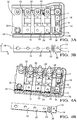
- Figs. 1A to 2B depict an electric assembly 1 with a straight rigid bus bar 2 according to an internal state of the art and a housing 3 made of plastic.
- the bus bar 2 is mechanically connected to the housing 3 by a screw 4.
- Multiple fuses 5, 6, 7 and 8 are clinched to the rigid bus bar 3 so that the fuses 5, 6, 7 and 8 are mechanically and electrically connected to the bus bar 2 at a first end of the fuse 5a, 6a, 7a, 8a.
- the fuses 5, 6, 7 and 8 are mechanically connected to the housing 3 at a second end 5b, 6b, 7b, 8b of the respective fuse 5, 6, 7, 8.
- a main direction F of the fuses is arranged perpendicular to a main direction B of the bus bar.
- the housing 3 expands more than the bus bar 2. This leads to the first ends of the fuses 5a, 6a, 7a, 8a which are attached to the bus bar 2 being pushed less in the main direction B of the bus bar 2 (in the Figures to the right) than the second ends of the fuses 5b, 6b, 7b, 8b which are connected to the housing 3.
- the reason for that is the difference in thermal expansion coefficient between the bus bar 2 and the housing 3, i.e. the housing 3 has a higher thermal expansion coefficient than the bus bar 2.
- a shear force is applied to the fuses 5, 6, 7, 8.
- This shear force can cause mechanical destruction of the fuses 5, 6, 7, 8 since the fuses 5, 6, 7, 8 are usually made of a thin web.
- the fuse 8 which is placed the furthest from the screw 4 and which usually has the smallest tripping current and the smallest mechanical load capacity can break due to the shear force applied to it.
- bus bars 10 to 710 are provided ( Fig. 3A to 10C ) that can avoid breakage of the fuse 8.
- a straight bus bar 10 according to a first embodiment of the invention is shown.
- the bus bar 10 comprises a rigid first portion 12 with a first contact surface 14 that is connected to a first end 16 of a first fuse 18 ( Fig. 3A and 4A ) and a rigid second portion 20 with a second contact surface 22 that is connected to a first end 24 of a second fuse 26.
- a third fuse 28, fourth fuse 30 and fifth fuse 32 are also connected to the bus bar 10 at their respective first ends.
- the bus bar 10 is mechanically connected to a housing 34 via a screw 35.
- the housing 34 is made of a non-conductive material with a higher thermal expansion coefficient than the material of the bus bar 10, e.g. plastic.
- the housing 34 and the bus bar 10 warm up due to a temperature rise around the bus bar 10 and the housing 34, they both expand in an axial direction i.e. the main direction B of the bus bar ( Fig. 3B ), and a lateral direction, i.e. the main direction F of the fuses.
- the bus bar 10 expands less than the housing 34 due to the lower thermal expansion coefficient of the bus bar 10.
- a resilient compensation portion 36 is provided between the rigid first portion 12 and the rigid second portion 20.
- the resilient compensation portion 36 according to the first embodiment of Figs. 3A to 4D comprises three lateral recesses, i.e. recesses that extend from a side surface laterally into the bus bar, a first lateral recess 38, a second lateral recess 40, and a third lateral recess 42.
- the first lateral recess 38 extends from a first side surface 44 into the bus bar 10 further than a centerline 46 ( Fig. 3B ) until only a first web portion 50 remains at an end of the lateral recess 38.
- the second lateral recess 40 extends from a second side surface 48 parallel to the first lateral recess further than the centerline 46 until only a second web portion 52 remains at the end of the second lateral recess 40.
- the third lateral recess 42 same as the first lateral recess 38, extends from the first side surface 44 into the bus bar 10 further than the centerline 46 until only a third web portion 54 remains at an end of the third lateral recess 42.
- the lateral recesses 38, 40 and 42 are spaced from each other in an axial direction so that lateral web portions 56 and 58 are formed respectively between the first lateral recess 38 and the second lateral recess 40 and between the second lateral recess 40 and the third lateral recess 42.
- the lateral web portions 56 and 58 have a similar width as the web portions 50, 52 and 54.
- the web portions 50, 56, 52, 58 and 54 together form a U-shaped web 60 extending from an eccentric part 62 of a face side 64 of the rigid second portion 20 to an eccentric part 66 of a face side 68 of the rigid first portion 12.
- the U-shaped web 60 forms a first bendable zone 70 at a connection between the first web portion 50 and the lateral web portion 56, a second bendable zone 72 between the lateral web portion 56 and the second web portion 52, a third bendable zone 74 between the second web portion 52 and the lateral web portion 58, and a fourth bendable zone 76 between the lateral web portion 58 and the third web portion 54.
- Each bendable zone 70, 72, 74 and 76 is formed by a 90° bend of the web 60.
- the housing 34 comprises an elevation 78 which projects into the third lateral recess 42.
- the elevation 78 forms a first side 80 contacting a face side 82 of the lateral web portion 58 and a second side 84, facing in the opposite direction of the first side 80, contacting the face side 68 of the rigid first portion 18.
- the elevation 78 is configured to keep the rigid first portion 12 in its axial position, even when the bus bar 10 expands or contracts due to a temperature change.
- the bus bar 10 and the housing 34 contract due to a drop in temperature, the bus bar 10 contracts less than the housing 34 in its axial direction, i.e. the bus bar 10 expands relative to the housing 34.
- the resilient compensation portion 36 compensates the axial expansion by being bendable in its bendable zones 70, 72, 74, and 76.
- the web 60 bends so that the widths of the lateral recesses 38, 40, and 42 get smaller. That means that the rigid second portion 20 moves towards the first lateral web portion 56 which bends the first lateral web portion 56 towards the first face side 64 of the rigid second portion 20. At the same time, the first lateral web portion 56 moves towards the second lateral web portion 58 which bends the first lateral web portion 56 and the second lateral web portion 58 towards each other. Further, the second lateral web portion 58 is bent towards the face side 68 of the first rigid portion 12.
- the resilient compensation portion 36 automatically elastically contracts and when the overall bus bar 10 contracts relative to the housing 34, the resilient compensation portion 36 automatically elastically expands. In other words, the length of the bus bar 10 is automatically adjusted to the thermal expansion or contraction of the housing 34.
- the compensation portion 36 is configured to protect the first fuse 18 by avoiding that shear force is applied to the fuse 18. Instead of transferring the axial expansion movement of the bus bar 10 to the fuse 18, the resilient compensation portion 36 stores the energy caused by the expansion movement of the bus bar 10 by elastic deformation.
- Fig. 5A to 5C depict a second embodiment of a bus bar 110 according to the invention.
- the bus bar 110 has a rigid first portion 112 and a rigid second portion 120 which are connected to each other by a resilient compensation portion 136.
- the resilient compensation portion comprises a first lateral recess 138 extending from a first side surface 144 into the bus bar 110 further than a centerline 146 until only a first web portion 150 remains at an end of the lateral recess 138.
- the resilient compensation portion also comprises a second lateral recess 140 extending from a second side surface 148 parallel to the first lateral recess 138 further than the centerline 146 until only a second web portion 152 remains at the end of the lateral recess 140.
- the lateral recesses 138 and 140 are spaced from each other in an axial direction so that a lateral web portion 156 is formed between the first lateral recess 138 and the second lateral recess 140.
- the lateral web portion 156 has a similar width than the web portions 150 and 152.
- the web portions 150, 156, and 152 together form a mirrored S-shaped web 160 extending from an eccentric part 162 of a face side 164 of the rigid second portion 120 to an eccentric part 166 of a face side 168 of the rigid first portion 112.
- the mirrored S-shaped web 160 forms a first bendable zone 170 at a connection between the first web portion 150 and the lateral web portion 156 and a second bendable zone 172 between the lateral web portion 156 and the second web portion 152.
- Each of the bendable zones 170 and 172 are formed by a 90° bend of the web 160.
- An oval hole 188 is formed in the rigid first portion 112 of the bus bar 110 to receive an oval elevation 178 ( Fig. 5A ) of a housing 134.
- the elevation's outer form is adapted to the hole's inner form so that the elevation's outer surface is contacting the hole's inner surface.
- the elevation 178 axially fixates the rigid first portion 112 so that no shear force is applied to a first fuse 118 connected to a first contact surface 114 of the rigid first portion 112.
- Fig. 6A to 6C depict a third embodiment of a bus bar 210 according to the invention.
- the bus bar 210 has a rigid first portion 212 and a rigid second portion 220 which are connected to each other by a resilient compensation portion 236.
- the resilient compensation portion 236 comprises four lateral recesses, a first lateral recess 238, a second lateral recess 240, a third lateral recess 242 and a fourth lateral recess 243.
- the first lateral recess 238 extends from a first side surface 244 into the bus bar 210 shorter than to a centerline 246.
- the second lateral recess 240 extends from a second side surface 248 in the direction of the first lateral recess 238 towards the first lateral recess 238 into the bus bar 210 shorter than to the centerline 246.
- the first lateral recess 238 and the second lateral recess 240 form a first web portion 250 that remains at the centerline 246 between the first lateral recess 238 and the second lateral recess 240 in a lateral direction.
- the first lateral recess 238 and the second lateral recess 240 taper towards the first web portion 250 at the centerline 146, i.e. the first and second lateral recess 238, 240 are wider at the first and second side surface 244, 248 and become narrower towards the centerline 246 of the bus bar 210.
- the fourth lateral recess 243 same as the second lateral recess 240, extends from the second side surface 248 in the direction of the third lateral recess 242 towards the third lateral recess 242 into the bus bar 210 shorter than to the centerline 246.
- the third lateral recess 242 and the fourth lateral recess 243 also taper towards the centerline 246, i.e. the third and fourth lateral recesses 242, 243 are wider at the first and second side surface 244, 248 and become narrower towards the centerline 246 of the bus bar 210.
- a hole-shaped recess 241 is formed in a center region of the resilient compensation portion 236.
- the hole-shaped recess 241 and the lateral recesses 238, 240, 242 and 243 form the web portions 250 and 252 as well as a first separate interconnecting part 290 and a second separate interconnecting part 292 which both connect the web portions 250 and 252.
- the interconnecting parts 290 and 292 are arch-shaped and together form an oval or O-shaped web 260.
- the O-shaped web 260 forms a first bendable zone 270 at an outer part of the first separate interconnecting part 290 and a second bendable zone 272 at an outer part of the second separate interconnecting part 292.
- Each bendable zone 270 and 272 is formed by a bend of the web 260 that is bent more than 90°.
- an oval hole 288 is formed in the rigid first portion 212 of the bus bar 210 to receive an elevation 278 ( Fig. 6A ) of a housing 234.
- the elevation's outer form is adapted to the hole's inner form so that the elevation's outer surface is contacting the hole's inner surface.
- the elevation 278 axially fixates the rigid first portion 212 so that no shear force is applied to a first fuse 218 connected to a first contact surface 214 of the rigid first portion 212.
- Fig. 7A to 7C depict a fourth embodiment of a bus bar 310 according to the invention.
- the bus bar 310 has a rigid first portion 312 and a rigid second portion 320 which are connected to each other by a resilient compensation portion 336.
- the resilient compensation portion 336 comprises three lateral recesses, a first lateral recess 338, a second lateral recess 340, and a third lateral recess 342.
- the first lateral recess 338 extends from a second side surface 348 into the bus bar 310 shorter than to a centerline 346.
- the second lateral recess 340 extends from a first side surface 344 shorter than to the centerline 346 into the bus bar 310.
- the third lateral recess 342, which is mirror-symmetrical to the first lateral recess 338, also extends from the second side surface 348 into the bus bar 10 shorter than to the centerline 346.
- Two arch-shaped recesses 339, 341 are formed in a center region of the resilient compensation portion 236. Together the lateral recesses 338, 340 and 342 and the arch-shaped recesses 339 and 341 form three arch-shaped connector-webs 359, 360, 361 that extend from a face side 364 of the rigid second portion 320 to a face side 368 of the rigid first portion 312. Instead of three arch-shaped connector webs, one, two, four or more arch-shaped connector webs could be used.
- the arch-shaped connector webs 359, 360, 361 each form a bendable zone 370, 372, 374.
- the bendable zones 370, 372 and 374 are all located on an axis extending in a lateral direction.
- Each bendable zone 370, 372, and 374 is formed by a bend of the respective web 359, 360, 361 of more than 90°.
- an oval hole 388 is formed in the rigid first portion 312 of the bus bar 310 to receive a laterally extending elevation 378 ( Fig. 7A ) of a housing 334.
- the elevation's outer form is adapted to the hole's inner form so that the elevation's outer surface is contacting the hole's inner surface in both axial directions.
- the elevation 378 axially fixates the rigid first portion 312 so that no shear force is applied to a first fuse 318 connected to a first contact surface 314 of the rigid first portion 312 due to a movement of the rigid first portion 312 relative to the housing 334.
- Fig. 8A to 8C depict a fifth embodiment of a bus bar 410 according to the invention.
- the bus bar 410 has a rigid first portion 412 and a rigid second portion 420 which are connected to each other by a resilient compensation portion 436.
- the resilient compensation portion 436 comprises a first triangular lateral recess 438 extending from a first side surface 444 into the bus bar 410 further than a centerline 446 until only a first web portion 450 remains at an end of the lateral recess 438.
- the resilient compensation portion 436 also comprises a second triangular lateral recess 440 extending from a second side surface 448 further than the centerline 446 until only a second web portion 452 remains at the end of the lateral recess 440.
- the lateral recesses 438 and 440 are spaced from each other in an axial direction so that a diagonal lateral web portion 456 is formed between the first lateral recess 438 and the second lateral recess 440.
- the diagonal lateral web portion 456 has a similar width than the web portions 450 and 452.
- the web portions 450, 456, and 452 together form a diagonal web 460 extending from an eccentric part 462 of a face side 464 of the rigid second portion 420 to an eccentric part 466 of a face side 468 of the rigid first portion 412.
- the diagonal web 460 forms a first bendable zone 470 at a connection between the first web portion 450 and the lateral web portion 456 and a second bendable zone 472 between the lateral web portion 456 and the second web portion 452.
- an oval hole 488 is formed in the rigid first portion 412 of the bus bar 410 to receive a laterally extending elevation 478 ( Fig. 8A ) of a housing 434.
- the elevation's outer form is adapted to the hole's inner form so that the elevation's outer surface is contacting the hole's inner surface in both axial directions.
- the elevation 478 therefore axially fixates the rigid first portion 412 so that no shear force caused by thermal expansion of the bus bar 410 is applied to a first fuse 418 connected to a first contact surface 414 of the rigid first portion 412.
- Fig. 9A to 9C depict a sixth embodiment of a bus bar 510 according to the invention.
- the bus bar 510 also has a rigid first portion 512 and a rigid second portion 520 which are connected to each other by a resilient compensation portion 536.
- the resilient compensation portion 536 is mirrored in comparison to the resilient compensation portion 436 of the fifth embodiment and thus comprises a first triangular lateral recess 538 extending from a second side surface 548 into the bus bar 510 further than a centerline 546 until only a first web portion 550 remains at an end of the lateral recess 538.
- the resilient compensation portion 536 also comprises a second triangular lateral recess 540 extending from a first side surface 544 further than the centerline 546 until only a second web portion 552 remains at the end of the lateral recess 540.
- the lateral recesses 538 and 540 are spaced from each other in an axial direction so that a diagonal lateral web portion 556 is formed between the first lateral recess 538 and the second lateral recess 540.
- the diagonal lateral web portion 556 has a similar width than the web portions 550 and 552.
- the web portions 550, 556, and 552 together form a diagonal web 560 extending from an eccentric part 562 of a face side 564 of the rigid second portion 520 to an eccentric part 566 of a face side 568 of the rigid first portion 512.
- the diagonal lateral web portion 456 of the fourth embodiment extends from the second side surface 448 of the rigid second portion 420 to the first side surface 444 of the rigid first portion 412
- the diagonal lateral web portion 556 of the fifth embodiment extends from the first side surface 544 of the rigid second portion 520 to the second side surface 548 of the rigid first portion 512.
- the diagonal web 560 forms a first bendable zone 570 at a connection between the first web portion 550 and the lateral web portion 556 and a second bendable zone 572 between the lateral web portion 556 and the second web portion 552.
- an elongated hole 588 is formed in the rigid first portion 512 of the bus bar 510 to receive a laterally extending elevation 578 ( Fig. 9A ) of a housing 534.
- the elevation's outer form is adapted to the hole's inner form so that the elevation 578 axially fixates the rigid first portion 512 in both directions.
- Figs. 10A to 10C depict a seventh embodiment of a bus bar 610 according to the invention.
- the bus bar 610 comprises a rigid first portion 612 and a rigid second portion 620 which are connected to each other by a resilient compensation portion 636.
- the resilient compensation portion 636 similarly to the resilient compensation portion 36 of the bus bar 10 according to the first embodiment, comprises three lateral recesses, a first lateral recess 638, a second lateral recess 640, and a third lateral recess 642.
- the first lateral recess 638 extends from a second side surface 648 into the bus bar 610 further than a centerline 646 until only a first web portion 650 remains at an end of the first lateral recess 638.
- the second lateral recess 640 extends from a first side surface 644 parallel to the first lateral recess further than the centerline 646 until only a second web portion 652 remains at the end of the second lateral recess 640.
- the third lateral recess 642 same as the first lateral recess 638, extends from the second side surface 648 into the bus bar 610 further than the centerline 646 until only a third web portion 654 remains at an end of the third lateral recess 642.
- the lateral recesses 638, 640 and 642 are spaced from each other in an axial direction so that lateral web portions 656 and 658 are formed respectively between the first lateral recess 638 and the second lateral recess 640 and between the second lateral recess 640 and the third lateral recess 642.
- the lateral web portions 656 and 658 have a similar width than the web portions 650, 652 and 654.
- the web portions 650, 656, 652, 658 and 654 together form a U-shaped web 660 extending from an eccentric part 662 of a face side 664 of the rigid second portion 620 to an eccentric part 666 of a face side 668 of the rigid first portion 612.
- the compensation portion 636 has narrow lateral recesses 638, 640 and 642, i.e. a width of the lateral recesses 638, 640 and 642 is smaller than the width of the lateral web portions 656 and 658.
- the U-shaped web 660 forms a first bendable zone 670 at a connection between the first web portion 650 and the lateral web portion 656, a second bendable zone 672 between the lateral web portion 656 and the second web portion 652, a third bendable zone 674 between the second web portion 652 and the lateral web portion 658, and a fourth bendable zone 676 between the lateral web portion 658 and the third web portion 654.
- Each bendable zone 670, 672, 674 and 676 is formed by a 90° bend of the web 660.
- an oval hole 688 is formed in the rigid first portion 612 of the bus bar 610 to receive an elevation 678 ( Fig. 10A ) of a housing 634.
- the elevation's outer form is also adapted to the hole's inner form so that the elevation 678 axially fixates the rigid first portion 612 in both axial directions.
Landscapes
- Engineering & Computer Science (AREA)
- Power Engineering (AREA)
- Mechanical Engineering (AREA)
- Fuses (AREA)
- Details Of Connecting Devices For Male And Female Coupling (AREA)
Abstract
A straight bus bar defining an axial direction and having a rigid first portion with a first contact surface connectable to a first fuse, an axially spaced rigid second portion with a second contact surface connectable to a second fuse, and a connecting portion electrically connecting the first portion and the second portion, wherein the connecting portion is a resilient compensation portion having at least two lateral recesses extending from opposite sides into the bus bar making the connecting portion elastically bendable to allow a relative axial movement of the first and second portions when an axial force is applied to the bus bar.
Description
- The present invention relates to a straight bus bar defining an axial direction, and more particularly to a straight bus bar that is used in a vehicle.
- A straight bus bar can be used in a vehicle's electrical system to electrically connect multiple midi fuses to it. In an internally known design, the bus bar is made of rigid conductive metal and is mechanically and electrically connected to one end of a fuse and the other end of the fuse is mechanically connected to a housing made of non-conductive plastic. The main direction of the fuse is arranged perpendicular to the axial direction of the bus bar. When the vehicle is exposed to hot or cold climate conditions, the bus bar and the housing will thermally expand or contract due to a change of temperature. A problem occurs due to the fact that the bus bar made of metal and the housing made of plastic have different thermal expansion coefficients. When the bus bar and the housing heat up, the bus bar will expand less in its axial direction due to the lower thermal expansion coefficient than the housing will expand in the same direction. As a result, the fuse between the bus bar and the housing will experience a shear force. Since the fuse is mechanically weak, it can break in high or low temperature regions such as >130°C or <-40°C. This causes discomfort for the owner of the vehicle because functionality of the vehicle is lost.
- Accordingly, it is an object of the invention to provide an improved bus bar that assures that an attached fuse does not break when the bus bar expands or contracts relative to a housing attached to the bus bar and the fuse.
- The object is satisfied by a straight bus bar in accordance with
claim 1. The bus bar of the invention defines an axial direction and has a rigid first portion with a first contact surface connectable to a first fuse, an axially spaced rigid second portion with a second contact surface connectable to a second fuse, and a connecting portion mechanically and electrically connecting the first portion and the second portion. The connecting portion is a resilient compensation portion having at least two lateral recesses extending from opposite sides into the bus bar making the connecting portion elastically bendable to allow a relative axial movement of the first and second portions when an axial force is applied to the bus bar. - More specifically, the straight bus bar has a length in the axial direction, a width and a height. The height is preferably smaller than the width and the length. Along the length of the bus bar, there is the first portion, followed by the connecting portion, again followed by the second portion. Due to each of the lateral recesses, the width of the bus bar is smaller in a section of the connecting portion. The connecting portion has a shape which allows a section of the connecting portion, a bendable zone, to elastically bend around a normal axis extending in the height direction of the bus bar. The shape of the connecting portion allows a relative axial movement of the first and second portions when an axial force is applied to the bus bar.
- Advantageous embodiments of the bus bar and an electric assembly in which the bus bar can be used can be taken from the following description, the dependent claims and the drawings.
- In accordance with an embodiment, the connecting portion comprises three lateral recesses wherein two recesses extend from the same side axially spaced from another into the bus bar. This improves the resiliency of the connection region so that relative axial movement of the first and second portions is achieved with less axial force applied to the bus bar.
- According to a further embodiment, the connecting portion consists of a single connector web. This simplifies the manufacturing process of the bus bar.
- In another embodiment, the connector web extends from an eccentric part of a face side of the first portion to any part of a face side of the second portion or from any part of a face side of the first portion to an eccentric part of a face side of the second portion. The connector web can extend from an eccentric part of a face side of the first portion to an eccentric part of a face side of the second portion. In particular, the connector web extends from an outer end of the face side of the first portion to a part of a face side of the second portion or from any part of the face side of the first portion to an outer end of a face side of the second portion.
- The connector web can extend from an outer end of the face side of the first portion to an outer end of a face side of the second portion. In general, the further away from a centric part the connector web starts, the more resiliency of the connection region can be expected.
- According to a further embodiment, the connector web is generally U-shaped or V-shaped. That means that the connector web extends along a path that is generally U-shaped or V-shaped. This shape has shown good resiliency and can be manufactured in a simple cutting process.
- According to another embodiment, the connector web extends from a centric part of a face side of the first portion to a centric part of a face side of the second portion. The connector web then comprises a bend which ensures that the connector is bendable.
- In a further embodiment, the connector comprises two separate interconnecting parts that are preferably formed mirror-symmetrical to each other. This helps to ensure that the first portion and the second portion stay aligned to each other in the axial direction.
- According to another embodiment, the connecting portion comprises at least two connectors. The connecting portion can comprise at least three connectors. This can improve the electricity transmission of the bus bar. In particular, the connecting portion consists of at least two connectors. For example, the connecting portion can consist of two connectors or three connectors.
- According to another aspect of the invention, a bus bar defining an axial direction and having a rigid first portion with a first contact surface connectable to a first fuse, an axially spaced rigid second portion with a second contact surface connectable to a second fuse, and a resilient compensation portion mechanically and electrically connecting the first portion and the second portion is used to electrically and mechanically connect at least two separate fuses. The resilient compensation portion is elastically deformable to allow a relative axial movement of the first and second portions when an axial force is applied to the bus bar
- The bus bar is preferably configured according to one of the embodiments disclosed above.
- The bus bar is preferably used to protect a fuse from being mechanically destroyed due to a different thermal expansion of the bus bar in comparison to a housing connected to the fuse and the bus bar.
- According to a further aspect of the invention, an electric assembly comprising a bus bar according to any one of the above described embodiments and a fuse is provided. Additionally, a housing made of a material having a different coefficient of thermal expansion than the bus bar can be provided.
- According to an embodiment, a first end of the fuse is mechanically and electrically connected to the first contact surface of the first portion of the bus bar and a second end of the fuse is mechanically connected to the housing. In this arrangement, the bus bar comprising the connecting portion that is a resilient compensation portion is helpful to avoid breaking of the fuse due to shear forces caused by relative thermal expansion of the bus bar with respect to the housing.
- In order to assure that the first portion of the bus bar does not move relative to the housing when the bus bar and the housing are exposed to a temperature change, the housing can be mechanically, in particular positively, connected to the first portion of the bus bar so that axial movement of the first portion relative to the housing is restricted in at least one axial direction.
- In a further embodiment, the housing comprises an elevation contacting a first face side of the first portion to axially fixate the first portion so that axial movement of the first portion in a first axial direction relative to the housing is restricted by the elevation. In the context of this disclosure, a face side of the bus bar is any side of the bus bar that is approximately facing in the axial direction of the bus bar. The advantage of this embodiment is that the first portion of a generally cuboid bus bar having at least one lateral recess or a hole can be safely secured to the housing.
- According to another embodiment, the elevation further contacts a second face side of the bus bar to axially fixate the first portion so that axial movement of the first portion in an opposite second axial direction relative to the housing is restricted by the elevation. The first portion is therefore axially fixed in both directions. The elevation can contact a face side of the connecting portion, i.e. the face side can be formed on a face side of a web of the connecting portion.
- In a further embodiment, the second portion comprises a hole which is configured to receive the elevation. The hole can have an inner axial extend that is equal to the axial extend of the elevation. Then, the first portion is axially fixed to the housing in both axial directions. In particular, the hole can have the form and size of the elevation. In this embodiment, the first portion is fixed to the housing in two perpendicular directions.
- The bus bar can be especially helpful when the fuse is a midi fuse. The fuse can have a first minimum cross-section and the connecting portion can have a second combined minimum cross-section that is larger than the first minimum cross-section of the fuse. A combined minimum cross section of the connecting portion is defined as the smallest cross section of the single connector web, if the connecting portion consists of a single connector web, or of the smallest cross sections of multiple connector webs combined, if the connecting portion consists of multiple connector webs.
- According to another embodiment, multiple fuses are connected to the bus bar wherein the fuse with the smallest tripping current is connected to the first contact surface of the first portion. The fuse with the smallest tripping current is usually the mechanically weakest fuse. When the weakest fuse is connected to the first contact surface, it is placed closely to the resilient compensation portion of the bus bar. This helps protecting the mechanically weakest fuse against shear force since the resilient compensation portion is able to compensate for the relative axial movement of the bus bar and the housing due to a change of temperature.
- In an embodiment, the first contact surface of the first portion is placed at an end position of the bus bar.
- While the invention is illustrated with a bus bar only having one resilient compensation portion, it is understood that the bus bar may comprise two or more resilient compensation portions.
- The invention will now be described in more detail with reference to the drawings. In the drawings, like or reference characters or reference signs increased by a hundred denote corresponding features consistently throughout similar embodiments.
- Fig. 1A
- shows a top view of an electric assembly with a bus bar according to internal state of the art.
- Fig. 1B
- shows a top view of the bus bar of
Fig. 1A . - Fig. 2A
- shows a perspective view of the electric assembly of
Fig. 1A . - Fig. 2B
- shows a perspective view of the bus bar of
Fig. 1A . - Fig. 3A
- shows a top view of an electric assembly with a bus bar according to a first embodiment of the present disclosure.
- Fig. 3B
- shows a top view of the bus bar of
Fig. 3A . - Fig. 4A
- shows a perspective view of the electric assembly of
Fig. 3A . - Fig. 4B
- shows a perspective view of the bus bar of
Fig. 3A . - Fig. 4C
- shows a detail view of
Fig. 4A . - Fig. 4D
- shows a detail view of
Fig. 4B . - Fig. 5A
- shows a perspective view of an electric assembly with a bus bar according to a second embodiment of the present disclosure.
- Fig. 5B
- shows a perspective view of the bus bar of
Fig. 5A . - Fig. 5C
- shows a detail view of
Fig. 5B . - Fig. 6A
- shows a perspective view of an electric assembly with a bus bar according to a third embodiment of the present disclosure.
- Fig. 6B
- shows a perspective view of the bus bar of
Fig. 6A . - Fig. 6C
- shows a detail view of
Fig. 6B . - Fig. 7A
- shows a perspective view of an electric assembly with a bus bar according to a fourth embodiment of the present disclosure.
- Fig. 7B
- shows a perspective view of the bus bar of
Fig. 7A . - Fig. 7C
- shows a detail view of
Fig. 7B . - Fig. 8A
- shows a perspective view of an electric assembly with a bus bar according to a fifth embodiment of the present disclosure.
- Fig. 8B
- shows a perspective view of the bus bar of
Fig. 8A . - Fig. 8C
- shows a detail view of
Fig. 8B . - Fig. 9A
- shows a perspective view of an electric assembly with a bus bar according to a sixth embodiment of the present disclosure.
- Fig. 9B
- shows a perspective view of the bus bar of
Fig. 9A . - Fig. 9C
- shows a detail view of
Fig. 9B . - Fig. 10A
- shows a perspective view of an electric assembly with a bus bar according to a seventh embodiment of the present disclosure.
- Fig. 10B
- shows a perspective view of the bus bar of
Fig. 10A . - Fig. 10C
- shows a detail view of
Fig. 10B . -
Figs. 1A to 2B depict anelectric assembly 1 with a straightrigid bus bar 2 according to an internal state of the art and ahousing 3 made of plastic. Thebus bar 2 is mechanically connected to thehousing 3 by ascrew 4. Multiple fuses 5, 6, 7 and 8 are clinched to therigid bus bar 3 so that thefuses bus bar 2 at a first end of thefuse fuses housing 3 at asecond end respective fuse bus bar 2 and thehousing 3 thermally expand in the main direction B due to a rise of temperature of thebus bar 2, thehousing 3 expands more than thebus bar 2. This leads to the first ends of thefuses bus bar 2 being pushed less in the main direction B of the bus bar 2 (in the Figures to the right) than the second ends of thefuses housing 3. The reason for that is the difference in thermal expansion coefficient between thebus bar 2 and thehousing 3, i.e. thehousing 3 has a higher thermal expansion coefficient than thebus bar 2. Due to different movement of the first end of thefuses fuses fuses fuses fuses fuse 8, which is placed the furthest from thescrew 4 and which usually has the smallest tripping current and the smallest mechanical load capacity can break due to the shear force applied to it. - In order to solve this issue, a variety of
bus bars 10 to 710 are provided (Fig. 3A to 10C ) that can avoid breakage of thefuse 8. - In
Figs. 3A to 4D , astraight bus bar 10 according to a first embodiment of the invention is shown. Thebus bar 10 comprises a rigidfirst portion 12 with afirst contact surface 14 that is connected to afirst end 16 of a first fuse 18 (Fig. 3A and 4A ) and a rigidsecond portion 20 with asecond contact surface 22 that is connected to afirst end 24 of asecond fuse 26. Athird fuse 28,fourth fuse 30 andfifth fuse 32 are also connected to thebus bar 10 at their respective first ends. - The
bus bar 10 is mechanically connected to ahousing 34 via ascrew 35. Thehousing 34 is made of a non-conductive material with a higher thermal expansion coefficient than the material of thebus bar 10, e.g. plastic. Thus, when thehousing 34 and thebus bar 10 warm up due to a temperature rise around thebus bar 10 and thehousing 34, they both expand in an axial direction i.e. the main direction B of the bus bar (Fig. 3B ), and a lateral direction, i.e. the main direction F of the fuses. However, thebus bar 10 expands less than thehousing 34 due to the lower thermal expansion coefficient of thebus bar 10. In order to compensate for the lower expansion in the axial direction, aresilient compensation portion 36 is provided between the rigidfirst portion 12 and the rigidsecond portion 20. - The
resilient compensation portion 36 according to the first embodiment ofFigs. 3A to 4D comprises three lateral recesses, i.e. recesses that extend from a side surface laterally into the bus bar, a firstlateral recess 38, a secondlateral recess 40, and a thirdlateral recess 42. The firstlateral recess 38 extends from afirst side surface 44 into thebus bar 10 further than a centerline 46 (Fig. 3B ) until only afirst web portion 50 remains at an end of thelateral recess 38. The secondlateral recess 40 extends from asecond side surface 48 parallel to the first lateral recess further than thecenterline 46 until only asecond web portion 52 remains at the end of the secondlateral recess 40. The thirdlateral recess 42, same as the firstlateral recess 38, extends from thefirst side surface 44 into thebus bar 10 further than thecenterline 46 until only athird web portion 54 remains at an end of the thirdlateral recess 42. The lateral recesses 38, 40 and 42 are spaced from each other in an axial direction so thatlateral web portions lateral recess 38 and the secondlateral recess 40 and between the secondlateral recess 40 and the thirdlateral recess 42. Thelateral web portions web portions web portions U-shaped web 60 extending from aneccentric part 62 of aface side 64 of the rigidsecond portion 20 to aneccentric part 66 of aface side 68 of the rigidfirst portion 12. - The
U-shaped web 60 forms a firstbendable zone 70 at a connection between thefirst web portion 50 and thelateral web portion 56, a secondbendable zone 72 between thelateral web portion 56 and thesecond web portion 52, a thirdbendable zone 74 between thesecond web portion 52 and thelateral web portion 58, and a fourthbendable zone 76 between thelateral web portion 58 and thethird web portion 54. Eachbendable zone web 60. - The
housing 34 comprises anelevation 78 which projects into the thirdlateral recess 42. Theelevation 78 forms afirst side 80 contacting aface side 82 of thelateral web portion 58 and asecond side 84, facing in the opposite direction of thefirst side 80, contacting theface side 68 of the rigidfirst portion 18. Theelevation 78 is configured to keep the rigidfirst portion 12 in its axial position, even when thebus bar 10 expands or contracts due to a temperature change. When thebus bar 10 and thehousing 34 contract due to a drop in temperature, thebus bar 10 contracts less than thehousing 34 in its axial direction, i.e. thebus bar 10 expands relative to thehousing 34. Theresilient compensation portion 36 compensates the axial expansion by being bendable in itsbendable zones web 60 bends so that the widths of the lateral recesses 38, 40, and 42 get smaller. That means that the rigidsecond portion 20 moves towards the firstlateral web portion 56 which bends the firstlateral web portion 56 towards thefirst face side 64 of the rigidsecond portion 20. At the same time, the firstlateral web portion 56 moves towards the secondlateral web portion 58 which bends the firstlateral web portion 56 and the secondlateral web portion 58 towards each other. Further, the secondlateral web portion 58 is bent towards theface side 68 of the firstrigid portion 12. In summary, when theoverall bus bar 10 expands relative to thehousing 34, theresilient compensation portion 36 automatically elastically contracts and when theoverall bus bar 10 contracts relative to thehousing 34, theresilient compensation portion 36 automatically elastically expands. In other words, the length of thebus bar 10 is automatically adjusted to the thermal expansion or contraction of thehousing 34. - The
compensation portion 36 is configured to protect thefirst fuse 18 by avoiding that shear force is applied to thefuse 18. Instead of transferring the axial expansion movement of thebus bar 10 to thefuse 18, theresilient compensation portion 36 stores the energy caused by the expansion movement of thebus bar 10 by elastic deformation. -
Fig. 5A to 5C depict a second embodiment of abus bar 110 according to the invention. Thebus bar 110 has a rigidfirst portion 112 and a rigidsecond portion 120 which are connected to each other by aresilient compensation portion 136. The resilient compensation portion comprises a firstlateral recess 138 extending from afirst side surface 144 into thebus bar 110 further than acenterline 146 until only afirst web portion 150 remains at an end of thelateral recess 138. The resilient compensation portion also comprises a secondlateral recess 140 extending from a second side surface 148 parallel to the firstlateral recess 138 further than thecenterline 146 until only asecond web portion 152 remains at the end of thelateral recess 140. - The lateral recesses 138 and 140 are spaced from each other in an axial direction so that a
lateral web portion 156 is formed between the firstlateral recess 138 and the secondlateral recess 140. Thelateral web portion 156 has a similar width than theweb portions web portions web 160 extending from aneccentric part 162 of aface side 164 of the rigidsecond portion 120 to aneccentric part 166 of aface side 168 of the rigidfirst portion 112. - The mirrored S-shaped
web 160 forms a firstbendable zone 170 at a connection between thefirst web portion 150 and thelateral web portion 156 and a secondbendable zone 172 between thelateral web portion 156 and thesecond web portion 152. Each of thebendable zones web 160. - An
oval hole 188 is formed in the rigidfirst portion 112 of thebus bar 110 to receive an oval elevation 178 (Fig. 5A ) of ahousing 134. The elevation's outer form is adapted to the hole's inner form so that the elevation's outer surface is contacting the hole's inner surface. Theelevation 178 axially fixates the rigidfirst portion 112 so that no shear force is applied to afirst fuse 118 connected to a first contact surface 114 of the rigidfirst portion 112. -
Fig. 6A to 6C depict a third embodiment of abus bar 210 according to the invention. Thebus bar 210 has a rigidfirst portion 212 and a rigidsecond portion 220 which are connected to each other by aresilient compensation portion 236. - The
resilient compensation portion 236 comprises four lateral recesses, a firstlateral recess 238, a secondlateral recess 240, a thirdlateral recess 242 and a fourthlateral recess 243. The firstlateral recess 238 extends from afirst side surface 244 into thebus bar 210 shorter than to acenterline 246. The secondlateral recess 240 extends from asecond side surface 248 in the direction of the firstlateral recess 238 towards the firstlateral recess 238 into thebus bar 210 shorter than to thecenterline 246. The firstlateral recess 238 and the secondlateral recess 240 form afirst web portion 250 that remains at thecenterline 246 between the firstlateral recess 238 and the secondlateral recess 240 in a lateral direction. The firstlateral recess 238 and the secondlateral recess 240 taper towards thefirst web portion 250 at thecenterline 146, i.e. the first and secondlateral recess second side surface centerline 246 of thebus bar 210. - The third
lateral recess 242, same as the firstlateral recess 238, extends from thefirst side surface 244 into thebus bar 210 shorter than to thecenterline 246. The fourthlateral recess 243, same as the secondlateral recess 240, extends from thesecond side surface 248 in the direction of the thirdlateral recess 242 towards the thirdlateral recess 242 into thebus bar 210 shorter than to thecenterline 246. The thirdlateral recess 242 and the fourthlateral recess 243 form asecond web portion 252 that remains at thecenterline 246 between the thirdlateral recess 242 and the fourthlateral recess 243 in a lateral direction. The thirdlateral recess 242 and the fourthlateral recess 243 also taper towards thecenterline 246, i.e. the third and fourth lateral recesses 242, 243 are wider at the first andsecond side surface centerline 246 of thebus bar 210. - Further, a hole-shaped
recess 241 is formed in a center region of theresilient compensation portion 236. The hole-shapedrecess 241 and the lateral recesses 238, 240, 242 and 243 form theweb portions part 290 and a second separate interconnectingpart 292 which both connect theweb portions parts web 260. Theweb portions parts resilient compensation portion 236 extending from acentric part 262 of aface side 264 of the rigidsecond portion 220 to acentric part 266 of aface side 268 of the rigidfirst portion 212. - The O-shaped
web 260 forms a firstbendable zone 270 at an outer part of the first separate interconnectingpart 290 and a secondbendable zone 272 at an outer part of the second separate interconnectingpart 292. Eachbendable zone web 260 that is bent more than 90°. - Similarly as in
embodiment 2, anoval hole 288 is formed in the rigidfirst portion 212 of thebus bar 210 to receive an elevation 278 (Fig. 6A ) of a housing 234. The elevation's outer form is adapted to the hole's inner form so that the elevation's outer surface is contacting the hole's inner surface. Theelevation 278 axially fixates the rigidfirst portion 212 so that no shear force is applied to afirst fuse 218 connected to afirst contact surface 214 of the rigidfirst portion 212. -
Fig. 7A to 7C depict a fourth embodiment of abus bar 310 according to the invention. Thebus bar 310 has a rigidfirst portion 312 and a rigidsecond portion 320 which are connected to each other by aresilient compensation portion 336. - The
resilient compensation portion 336 comprises three lateral recesses, a firstlateral recess 338, a secondlateral recess 340, and a thirdlateral recess 342. The firstlateral recess 338 extends from asecond side surface 348 into thebus bar 310 shorter than to acenterline 346. The secondlateral recess 340 extends from afirst side surface 344 shorter than to thecenterline 346 into thebus bar 310. The thirdlateral recess 342, which is mirror-symmetrical to the firstlateral recess 338, also extends from thesecond side surface 348 into thebus bar 10 shorter than to thecenterline 346. - Two arch-shaped
recesses resilient compensation portion 236. Together the lateral recesses 338, 340 and 342 and the arch-shapedrecesses webs second portion 320 to a face side 368 of the rigidfirst portion 312. Instead of three arch-shaped connector webs, one, two, four or more arch-shaped connector webs could be used. - The arch-shaped
connector webs bendable zone bendable zones bendable zone respective web - Similarly as in
embodiment oval hole 388 is formed in the rigidfirst portion 312 of thebus bar 310 to receive a laterally extending elevation 378 (Fig. 7A ) of ahousing 334. The elevation's outer form is adapted to the hole's inner form so that the elevation's outer surface is contacting the hole's inner surface in both axial directions. Theelevation 378 axially fixates the rigidfirst portion 312 so that no shear force is applied to afirst fuse 318 connected to afirst contact surface 314 of the rigidfirst portion 312 due to a movement of the rigidfirst portion 312 relative to thehousing 334. -
Fig. 8A to 8C depict a fifth embodiment of abus bar 410 according to the invention. Thebus bar 410 has a rigidfirst portion 412 and a rigidsecond portion 420 which are connected to each other by aresilient compensation portion 436. Theresilient compensation portion 436 comprises a first triangularlateral recess 438 extending from afirst side surface 444 into thebus bar 410 further than acenterline 446 until only afirst web portion 450 remains at an end of thelateral recess 438. Theresilient compensation portion 436 also comprises a second triangularlateral recess 440 extending from asecond side surface 448 further than thecenterline 446 until only asecond web portion 452 remains at the end of thelateral recess 440. - The lateral recesses 438 and 440 are spaced from each other in an axial direction so that a diagonal
lateral web portion 456 is formed between the firstlateral recess 438 and the secondlateral recess 440. The diagonallateral web portion 456 has a similar width than theweb portions web portions diagonal web 460 extending from aneccentric part 462 of aface side 464 of the rigidsecond portion 420 to aneccentric part 466 of aface side 468 of the rigidfirst portion 412. - The
diagonal web 460 forms a firstbendable zone 470 at a connection between thefirst web portion 450 and thelateral web portion 456 and a secondbendable zone 472 between thelateral web portion 456 and thesecond web portion 452. - In this embodiment also, an
oval hole 488 is formed in the rigidfirst portion 412 of thebus bar 410 to receive a laterally extending elevation 478 (Fig. 8A ) of a housing 434. As explained before, the elevation's outer form is adapted to the hole's inner form so that the elevation's outer surface is contacting the hole's inner surface in both axial directions. Theelevation 478 therefore axially fixates the rigidfirst portion 412 so that no shear force caused by thermal expansion of thebus bar 410 is applied to afirst fuse 418 connected to afirst contact surface 414 of the rigidfirst portion 412. -
Fig. 9A to 9C depict a sixth embodiment of abus bar 510 according to the invention. Thebus bar 510 also has a rigidfirst portion 512 and a rigidsecond portion 520 which are connected to each other by aresilient compensation portion 536. Theresilient compensation portion 536 is mirrored in comparison to theresilient compensation portion 436 of the fifth embodiment and thus comprises a first triangularlateral recess 538 extending from asecond side surface 548 into thebus bar 510 further than acenterline 546 until only afirst web portion 550 remains at an end of thelateral recess 538. Theresilient compensation portion 536 also comprises a second triangularlateral recess 540 extending from afirst side surface 544 further than thecenterline 546 until only asecond web portion 552 remains at the end of thelateral recess 540. - As already described for the fifth embodiment, the lateral recesses 538 and 540 are spaced from each other in an axial direction so that a diagonal
lateral web portion 556 is formed between the firstlateral recess 538 and the secondlateral recess 540. The diagonallateral web portion 556 has a similar width than theweb portions web portions diagonal web 560 extending from aneccentric part 562 of aface side 564 of the rigidsecond portion 520 to aneccentric part 566 of aface side 568 of the rigidfirst portion 512. In particular, while the diagonallateral web portion 456 of the fourth embodiment extends from thesecond side surface 448 of the rigidsecond portion 420 to thefirst side surface 444 of the rigidfirst portion 412, the diagonallateral web portion 556 of the fifth embodiment extends from thefirst side surface 544 of the rigidsecond portion 520 to thesecond side surface 548 of the rigidfirst portion 512. - The
diagonal web 560 forms a firstbendable zone 570 at a connection between thefirst web portion 550 and thelateral web portion 556 and a secondbendable zone 572 between thelateral web portion 556 and thesecond web portion 552. - In this embodiment also, an
elongated hole 588 is formed in the rigidfirst portion 512 of thebus bar 510 to receive a laterally extending elevation 578 (Fig. 9A ) of ahousing 534. As explained before, the elevation's outer form is adapted to the hole's inner form so that theelevation 578 axially fixates the rigidfirst portion 512 in both directions. -
Figs. 10A to 10C depict a seventh embodiment of abus bar 610 according to the invention. Thebus bar 610 comprises a rigidfirst portion 612 and a rigidsecond portion 620 which are connected to each other by aresilient compensation portion 636. - The
resilient compensation portion 636, similarly to theresilient compensation portion 36 of thebus bar 10 according to the first embodiment, comprises three lateral recesses, a firstlateral recess 638, a secondlateral recess 640, and a thirdlateral recess 642. The firstlateral recess 638 extends from asecond side surface 648 into thebus bar 610 further than acenterline 646 until only afirst web portion 650 remains at an end of the firstlateral recess 638. The secondlateral recess 640 extends from afirst side surface 644 parallel to the first lateral recess further than thecenterline 646 until only asecond web portion 652 remains at the end of the secondlateral recess 640. The thirdlateral recess 642, same as the firstlateral recess 638, extends from thesecond side surface 648 into thebus bar 610 further than thecenterline 646 until only athird web portion 654 remains at an end of the thirdlateral recess 642. The lateral recesses 638, 640 and 642 are spaced from each other in an axial direction so thatlateral web portions lateral recess 638 and the secondlateral recess 640 and between the secondlateral recess 640 and the thirdlateral recess 642. Thelateral web portions web portions web portions U-shaped web 660 extending from aneccentric part 662 of aface side 664 of the rigidsecond portion 620 to aneccentric part 666 of aface side 668 of the rigidfirst portion 612. In comparison to thecompensation portion 36 ofFigs. 3A to 4D , thecompensation portion 636 has narrowlateral recesses lateral web portions - The
U-shaped web 660 forms a firstbendable zone 670 at a connection between thefirst web portion 650 and thelateral web portion 656, a secondbendable zone 672 between thelateral web portion 656 and thesecond web portion 652, a thirdbendable zone 674 between thesecond web portion 652 and thelateral web portion 658, and a fourthbendable zone 676 between thelateral web portion 658 and thethird web portion 654. Eachbendable zone web 660. - In comparison to the first embodiment of
Figs. 3A to 4D where no hole for theelevation 78 is needed, anoval hole 688 is formed in the rigidfirst portion 612 of thebus bar 610 to receive an elevation 678 (Fig. 10A ) of ahousing 634. The elevation's outer form is also adapted to the hole's inner form so that theelevation 678 axially fixates the rigidfirst portion 612 in both axial directions. -
- 1
- electric assembly
- 2
- bus bar
- 3
- housing
- 4
- screw
- 5
- fuse
- 5a
- first end
- 5b
- second end
- 6
- fuse
- 6a
- first end
- 6b
- second end
- 7
- fuse
- 7a
- first end
- 7b
- second end
- 8
- fuse
- 8a
- first end
- 8b
- second end
- 10
- bus bar
- 12
- rigid first portion
- 14
- first contact surface
- 16
- first end
- 17
- second end
- 18
- first fuse
- 20
- rigid second portion
- 22
- second contact surface
- 24
- first end
- 26
- second fuse
- 28
- third fuse
- 30
- fourth fuse
- 32
- fifth fuse
- 34
- housing
- 35
- screw
- 36
- resilient compensation portion
- 38
- first lateral recess
- 40
- second lateral recess
- 42
- third lateral recess
- 44
- first side surface
- 46
- centerline
- 48
- second side surface
- 50
- first web portion
- 52
- second web portion
- 54
- third web portion
- 56
- lateral web portion
- 58
- lateral web portion
- 60
- web
- 62
- eccentric part
- 64
- face side
- 66
- eccentric part
- 68
- face side
- 70
- bendable zone
- 72
- bendable zone
- 74
- bendable zone
- 76
- bendable zone
- 78
- elevation
- 80
- first side
- 82
- face side
- 84
- second side
- 88
- hole
- 241
- hole-shaped recess
- 243
- fourth lateral recess
- 290
- separate interconnecting part
- 292
- separate interconnecting part
- 339
- arch-shaped recess
- 341
- arch-shaped recess
- 359
- web
- 361
- web
- B
- main direction of bus bar
- F
- main direction of fuse
Claims (15)
- A straight bus bar (10) defining an axial direction (B) and having
a rigid first portion (12) with a first contact surface (14) connectable to a first fuse (18),
an axially spaced rigid second portion (20) with a second contact surface (22) connectable to a second fuse (26), and
a connecting portion (36) mechanically and electrically connecting the first portion (12) and the second portion (20),
characterized in that
the connecting portion (36) is a resilient compensation portion having at least two lateral recesses (38, 40) extending from opposite sides (44, 48) into the bus bar (10) making the connecting portion (36) elastically bendable to allow a relative axial movement of the first and second portions (12, 20) when an axial force is applied to the bus bar (10). - Bus bar according to claim 1,
characterized in that
the connecting portion (36) comprises three lateral recesses (38, 40, 42) wherein two recesses (38, 42) extend from the same side (44) axially spaced from another into the bus bar (10). - Bus bar according to claim 1 or 2,
characterized in that
the connecting portion (36) consists of a single connector web (60). - Bus bar according to claim 3,
characterized in that
the connector web (60) extends from an eccentric part (66) of a face side (68) of the first portion (12) to an eccentric part (62) of a face side (64) of the rigid second portion (20). - Bus bar according to claim 3 or 4,
characterized in that
the connector web (60) is generally U-shaped or V-shaped. - Bus bar according to claim 3 or 5,
characterized in that
the connector web (260) extends from a centric part (266) of a face side (268) of the first portion (212) to a centric part (262) of a face side (264) of the rigid second portion (220) and comprises a bend (270), in particular wherein
the connector comprises two separate interconnecting parts (290, 292) that are preferably formed mirror-symmetrical to each other. - Bus bar according to claim 1 or 2,
characterized in that
the connecting portion (26) comprises at least two connectors (359, 360, 361). - Use of a bus bar (10) defining an axial direction (B) and having
a rigid first portion (12) with a first contact surface (14) connectable to a first fuse (18),
an axially spaced rigid second portion (20) with a second contact surface (22) connectable to a second fuse (26), and
a connecting portion (36) mechanically and electrically connecting the rigid first portion (12) and the rigid second portion (20),
wherein the connecting portion (36) is a resilient compensation portion that is elastically deformable to allow a relative axial movement of the rigid first and second portions (12, 20) when an axial force is applied to the bus bar to electrically and mechanically connect at least two separate fuses (18, 26), in particular wherein the bus bar is a bus bar (10) according to any one of claims 1 to 7. - Electric assembly comprising
a bus bar (10) according to any one of the preceding claims, a fuse (18) and a housing (34) made of a material having a different coefficient of thermal expansion than the bus bar (10), wherein a first end (16) of the fuse (18) is mechanically and electrically connected to the first contact surface (14) of the rigid first portion (12) of the bus bar (10) and a second end (17) of the fuse (18) is mechanically connected to the housing (34). - Electric assembly according to claim 9,
characterized in that
the housing (34) is mechanically, in particular positively, connected to the rigid first portion (12) of the bus bar so that axial movement of the rigid first portion (12) relative to the housing (34) is restricted in at least one axial direction (B). - Electric assembly according to claim 10,
characterized in that
the housing (34) comprises an elevation (78) contacting a first face side (68) of the rigid first portion (12) to axially fixate the rigid first portion (12) so that axial movement of the rigid first portion (12) in a first axial direction (B) relative to the housing (34) is restricted by the elevation (78). - Electric assembly according to claim 11,
characterized in that
the elevation (78) further contacts a second face side (68) of the bus bar (10), in particular of the connecting portion (36), to axially fixate the rigid first portion (12) so that axial movement of the first portion (12) in an opposite second axial direction (B) relative to the housing (34) is restricted by the elevation (78). - Electric assembly according to claim 11 or 12,
characterized in that
the rigid first portion (112) comprises a hole (188) which is configured to receive the elevation (178). - Electric assembly according to any one of claims 9 to 13,
characterized in that
the fuse (18) is a midi fuse having a first minimum cross-section and the connecting portion has a second combined minimum cross-section that is larger than the first minimum cross-section of the midi fuse (18). - Electric assembly according to any one of claims 8 to 13,
characterized in that
multiple fuses (18, 26, 28, 30, 32) are connected to the bus bar (10) wherein the fuse (18) with the smallest tripping current is connected to the first contact surface (14) of the rigid first portion (12), in particular wherein the first contact surface (14) of the rigid first portion (12) is placed at an end position of the bus bar (10).
Priority Applications (3)
| Application Number | Priority Date | Filing Date | Title |
|---|---|---|---|
| EP18171061.7A EP3567624A1 (en) | 2018-05-07 | 2018-05-07 | Bus bar |
| US16/372,957 US10632937B2 (en) | 2018-05-07 | 2019-04-02 | Bus bar |
| CN201910371145.5A CN110459345B (en) | 2018-05-07 | 2019-05-06 | Bus bar |
Applications Claiming Priority (1)
| Application Number | Priority Date | Filing Date | Title |
|---|---|---|---|
| EP18171061.7A EP3567624A1 (en) | 2018-05-07 | 2018-05-07 | Bus bar |
Publications (1)
| Publication Number | Publication Date |
|---|---|
| EP3567624A1 true EP3567624A1 (en) | 2019-11-13 |
Family
ID=62134114
Family Applications (1)
| Application Number | Title | Priority Date | Filing Date |
|---|---|---|---|
| EP18171061.7A Withdrawn EP3567624A1 (en) | 2018-05-07 | 2018-05-07 | Bus bar |
Country Status (3)
| Country | Link |
|---|---|
| US (1) | US10632937B2 (en) |
| EP (1) | EP3567624A1 (en) |
| CN (1) | CN110459345B (en) |
Families Citing this family (3)
| Publication number | Priority date | Publication date | Assignee | Title |
|---|---|---|---|---|
| DE102019133031B4 (en) * | 2019-12-04 | 2022-03-31 | Kromberg & Schubert Automotive Gmbh & Co. Kg | Current distribution arrangement with a decoupling element for thermally and mechanically decoupling a fuse from a busbar |
| US11888303B2 (en) | 2020-07-31 | 2024-01-30 | Aptiv Technologies Limited | Busbar connection systems and methods |
| CN117239497B (en) * | 2023-09-06 | 2026-01-16 | 苏州西典新能源汽车电子有限公司 | Switching structure of signal acquisition branch and bus bar for vehicle |
Citations (4)
| Publication number | Priority date | Publication date | Assignee | Title |
|---|---|---|---|---|
| US20020053456A1 (en) * | 2000-04-09 | 2002-05-09 | Shiro Nishida | Bus bar module |
| EP1498927A1 (en) * | 2003-07-14 | 2005-01-19 | Meccanotecnica Codognese S.p.A. | An improved high-current protection device |
| DE202009009607U1 (en) * | 2009-07-16 | 2009-09-10 | Taller Gmbh | Busbar with compensation section |
| US20130062937A1 (en) * | 2010-03-31 | 2013-03-14 | Lisa Draexlmaier Gmbh | Busbar for a power distributor in vehicles and power distributor having such a busbar |
Family Cites Families (9)
| Publication number | Priority date | Publication date | Assignee | Title |
|---|---|---|---|---|
| US5421751A (en) * | 1993-07-27 | 1995-06-06 | The Whitaker Corporation | Tappable bus bar |
| JP2004127698A (en) * | 2002-10-02 | 2004-04-22 | Yazaki Corp | Fusible link unit |
| US8048286B2 (en) * | 2006-07-11 | 2011-11-01 | Bharat Aluminum Company Limited | Aluminum reduction cell fuse technology |
| JP2012182864A (en) * | 2011-02-28 | 2012-09-20 | Togo Seisakusho Corp | Bus bar and method of manufacturing bus bar |
| DE202011050310U1 (en) * | 2011-05-31 | 2011-07-11 | Lisa Dräxlmaier GmbH | Angled midi or fuse |
| US9437386B2 (en) * | 2014-05-14 | 2016-09-06 | Pass & Seymour, Inc. | Protective wiring device |
| US9705121B2 (en) * | 2014-08-18 | 2017-07-11 | Johnson Controls Technology Company | Lead frame for a battery module |
| KR101937942B1 (en) * | 2015-07-13 | 2019-01-11 | 주식회사 엘지화학 | Bus-bar Structure |
| US9620763B1 (en) * | 2016-03-07 | 2017-04-11 | GS Yuasa Lithium Power Inc. | Connector assembly with integrated sense and balance line protection for multi-cell batteries |
-
2018
- 2018-05-07 EP EP18171061.7A patent/EP3567624A1/en not_active Withdrawn
-
2019
- 2019-04-02 US US16/372,957 patent/US10632937B2/en active Active
- 2019-05-06 CN CN201910371145.5A patent/CN110459345B/en active Active
Patent Citations (4)
| Publication number | Priority date | Publication date | Assignee | Title |
|---|---|---|---|---|
| US20020053456A1 (en) * | 2000-04-09 | 2002-05-09 | Shiro Nishida | Bus bar module |
| EP1498927A1 (en) * | 2003-07-14 | 2005-01-19 | Meccanotecnica Codognese S.p.A. | An improved high-current protection device |
| DE202009009607U1 (en) * | 2009-07-16 | 2009-09-10 | Taller Gmbh | Busbar with compensation section |
| US20130062937A1 (en) * | 2010-03-31 | 2013-03-14 | Lisa Draexlmaier Gmbh | Busbar for a power distributor in vehicles and power distributor having such a busbar |
Also Published As
| Publication number | Publication date |
|---|---|
| US20190337470A1 (en) | 2019-11-07 |
| US10632937B2 (en) | 2020-04-28 |
| CN110459345B (en) | 2021-02-02 |
| CN110459345A (en) | 2019-11-15 |
Similar Documents
| Publication | Publication Date | Title |
|---|---|---|
| KR0144438B1 (en) | Chip fuse | |
| US5551897A (en) | Electrical contact | |
| JP4716529B2 (en) | Contacts and electrical connectors | |
| US9455516B2 (en) | Contact socket for an electrical plug connector | |
| US10632937B2 (en) | Bus bar | |
| US5106324A (en) | Joint terminal | |
| CN113328277A (en) | Conical contact spring sleeve and electrical connector and electrical plug connection | |
| US5488346A (en) | Connection terminal for fuse | |
| EP3595092A1 (en) | Connector, header and connection device | |
| JP4607749B2 (en) | Female connector terminal and female connector | |
| KR20120100974A (en) | Electronic component | |
| EP3996212A1 (en) | Electrical connector assembly | |
| EP4054009B1 (en) | Female electrical bus bar connector and method of forming same | |
| KR20080068558A (en) | Electrical socket terminal with contact stabilizer | |
| CN118235300A (en) | Connector, connector assembly, and tool and method for assembling connector assembly | |
| CN108736212B (en) | Contact terminal assembled from at least two components | |
| EP4184723A1 (en) | Electric terminal, terminal assembly, connector assembly and method for manufacturing the terminal assembly | |
| KR101979226B1 (en) | Busbar for multi-fuse | |
| US20050009414A1 (en) | Contact element for an electrical plug connection | |
| EP3614412A1 (en) | Connecting element | |
| EP2341522B1 (en) | Fusing device and battery assembly comprising the same | |
| JP2005528767A (en) | Welded meander contact | |
| JP3207480U (en) | Thermal destruction protection member and outlet using the same | |
| EP3525291B1 (en) | Electrical terminal assembly | |
| KR200441583Y1 (en) | Fuse Insert Terminal |
Legal Events
| Date | Code | Title | Description |
|---|---|---|---|
| PUAI | Public reference made under article 153(3) epc to a published international application that has entered the european phase |
Free format text: ORIGINAL CODE: 0009012 |
|
| AK | Designated contracting states |
Kind code of ref document: A1 Designated state(s): AL AT BE BG CH CY CZ DE DK EE ES FI FR GB GR HR HU IE IS IT LI LT LU LV MC MK MT NL NO PL PT RO RS SE SI SK SM TR |
|
| AX | Request for extension of the european patent |
Extension state: BA ME |
|
| STAA | Information on the status of an ep patent application or granted ep patent |
Free format text: STATUS: THE APPLICATION IS DEEMED TO BE WITHDRAWN |
|
| 18D | Application deemed to be withdrawn |
Effective date: 20200603 |