EP3567413B1 - Virtual reality head-mounted apparatus - Google Patents
Virtual reality head-mounted apparatus Download PDFInfo
- Publication number
- EP3567413B1 EP3567413B1 EP18757692.1A EP18757692A EP3567413B1 EP 3567413 B1 EP3567413 B1 EP 3567413B1 EP 18757692 A EP18757692 A EP 18757692A EP 3567413 B1 EP3567413 B1 EP 3567413B1
- Authority
- EP
- European Patent Office
- Prior art keywords
- camera
- user
- eye
- convex lens
- pattern features
- Prior art date
- Legal status (The legal status is an assumption and is not a legal conclusion. Google has not performed a legal analysis and makes no representation as to the accuracy of the status listed.)
- Active
Links
Images
Classifications
-
- G—PHYSICS
- G02—OPTICS
- G02B—OPTICAL ELEMENTS, SYSTEMS OR APPARATUS
- G02B27/00—Optical systems or apparatus not provided for by any of the groups G02B1/00 - G02B26/00, G02B30/00
- G02B27/01—Head-up displays
- G02B27/017—Head mounted
-
- G—PHYSICS
- G02—OPTICS
- G02B—OPTICAL ELEMENTS, SYSTEMS OR APPARATUS
- G02B27/00—Optical systems or apparatus not provided for by any of the groups G02B1/00 - G02B26/00, G02B30/00
- G02B27/0093—Optical systems or apparatus not provided for by any of the groups G02B1/00 - G02B26/00, G02B30/00 with means for monitoring data relating to the user, e.g. head-tracking, eye-tracking
-
- G—PHYSICS
- G02—OPTICS
- G02B—OPTICAL ELEMENTS, SYSTEMS OR APPARATUS
- G02B27/00—Optical systems or apparatus not provided for by any of the groups G02B1/00 - G02B26/00, G02B30/00
- G02B27/01—Head-up displays
- G02B27/017—Head mounted
- G02B27/0172—Head mounted characterised by optical features
-
- G—PHYSICS
- G06—COMPUTING OR CALCULATING; COUNTING
- G06F—ELECTRIC DIGITAL DATA PROCESSING
- G06F21/00—Security arrangements for protecting computers, components thereof, programs or data against unauthorised activity
- G06F21/30—Authentication, i.e. establishing the identity or authorisation of security principals
- G06F21/31—User authentication
- G06F21/32—User authentication using biometric data, e.g. fingerprints, iris scans or voiceprints
-
- G—PHYSICS
- G06—COMPUTING OR CALCULATING; COUNTING
- G06F—ELECTRIC DIGITAL DATA PROCESSING
- G06F3/00—Input arrangements for transferring data to be processed into a form capable of being handled by the computer; Output arrangements for transferring data from processing unit to output unit, e.g. interface arrangements
- G06F3/01—Input arrangements or combined input and output arrangements for interaction between user and computer
- G06F3/011—Arrangements for interaction with the human body, e.g. for user immersion in virtual reality
- G06F3/013—Eye tracking input arrangements
-
- H—ELECTRICITY
- H04—ELECTRIC COMMUNICATION TECHNIQUE
- H04N—PICTORIAL COMMUNICATION, e.g. TELEVISION
- H04N23/00—Cameras or camera modules comprising electronic image sensors; Control thereof
- H04N23/10—Cameras or camera modules comprising electronic image sensors; Control thereof for generating image signals from different wavelengths
- H04N23/11—Cameras or camera modules comprising electronic image sensors; Control thereof for generating image signals from different wavelengths for generating image signals from visible and infrared light wavelengths
-
- H—ELECTRICITY
- H04—ELECTRIC COMMUNICATION TECHNIQUE
- H04N—PICTORIAL COMMUNICATION, e.g. TELEVISION
- H04N23/00—Cameras or camera modules comprising electronic image sensors; Control thereof
- H04N23/57—Mechanical or electrical details of cameras or camera modules specially adapted for being embedded in other devices
-
- H—ELECTRICITY
- H04—ELECTRIC COMMUNICATION TECHNIQUE
- H04N—PICTORIAL COMMUNICATION, e.g. TELEVISION
- H04N23/00—Cameras or camera modules comprising electronic image sensors; Control thereof
- H04N23/60—Control of cameras or camera modules
- H04N23/695—Control of camera direction for changing a field of view, e.g. pan, tilt or based on tracking of objects
-
- G—PHYSICS
- G02—OPTICS
- G02B—OPTICAL ELEMENTS, SYSTEMS OR APPARATUS
- G02B27/00—Optical systems or apparatus not provided for by any of the groups G02B1/00 - G02B26/00, G02B30/00
- G02B27/01—Head-up displays
- G02B27/0101—Head-up displays characterised by optical features
- G02B2027/0138—Head-up displays characterised by optical features comprising image capture systems, e.g. camera
Definitions
- This application relates to the technical field of virtual reality, and in particular, to a virtual reality head-mounted apparatus.
- Virtual reality (VR) technology is a technology that comprehensively utilizes a computer graphics system and various control interfaces to generate an interactive three-dimensional interaction environment on a computer to provide users with immersive experience.
- a user may wear a virtual reality head-mounted apparatus, such as VR glasses or a VR helmet, to obtain corresponding virtual reality experience.
- US 2015009574 A1 discloses a HMD apparatus with an imaging optical system for each one of the eyes of a user, which includes at least one display unit to be viewed by the respective eye.
- WO2017026371 A1 and US 2018/21821 Al describe a head-mounted display in which it is easy to photograph eyes of a user that wears the head-mounted display.
- HMD head mounted device
- an imaging unit configured to capture at least one image of a partial region of an iris
- ECG electrocardiogram
- control unit configured to acquire at least one image of the partial region of the iris and ECG signals, and authenticate a user by using the acquired image(s) of the partial region of the iris and the ECG signals.
- Hayden Scott "Hands On: SMIs Gear VR Eye Tracking is Accurate, Fast and Lightweight" (https:// www.roadtovr.com/hands-smis-gear-vr-eye-tracking-accurate-fast-lightweight) discloses a Samsung Gear VR Headset as a support for attaching a mobile phone and playing VR content but enhanced with "a small pair of cameras placed on either side of the headset" - part of the SMI eye tracking kit.
- the invention provides a virtual reality head-mounted apparatus as set out in the accompanying claims. Also disclosed herein is a virtual reality head-mounted apparatus, which can perform, by acquiring eye pattern features of a user, an identity recognition operation on the user wearing the virtual reality head-mounted apparatus quickly and accurately.
- a first aspect of this application is directed to a virtual reality head-mounted apparatus, including: an apparatus body, the apparatus body including a convex lens and a camera, the camera being located on a user side of the convex lens, and a lens of the camera facing an eye of the user to acquire eye pattern features of the user.
- the camera is located below the convex lens, and the camera tilts upward by a first preset angle, so that the lens of the camera faces the eye of the user.
- the camera is located above the convex lens, and the camera tilts downward by a second preset angle, so that the lens of the camera faces the eye of the user.
- the camera is located at one of two convex lenses provided in the apparatus body for acquiring eye pattern features of the eye of the user corresponding to the one of the two convex lenses.
- the apparatus body includes two cameras, respectively located at two convex lenses in the apparatus body for respectively acquiring eye pattern features of the eye of the user corresponding to each convex lens.
- the camera is provided outside a visible area of the convex lens with respect to the user.
- the camera is installed in a position in close contact with the corresponding convex lens.
- the camera may be an RGB camera or an RGB-IR camera.
- the apparatus further includes:
- the apparatus further includes: an adjustment component, the adjustment component being capable of performing angle adjustment on the camera, such that the lens of the camera tilts toward the eye of the user.
- a camera is provided in an apparatus body of the virtual reality head-mounted apparatus, and a lens of the camera faces an eye of a user, so that eye pattern features of the user can be acquired by the camera without interfering with the user's viewing of virtual reality display content.
- Identity information of the user may be efficiently and quickly verified by comparing and identifying the eye pattern features, thereby improving the security of the virtual reality head-mounted apparatus.
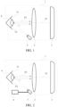
- FIG. 1 is a side cross-sectional view of a VR helmet provided by an exemplary embodiment of this application.
- a convex lens 2 and a VR playing component 3 are provided in an apparatus body 1 of a VR helmet.
- the convex lens 2 is located between a user ( FIG. 1 shows an eye 4 of the user) and the VR playing component 3 in the apparatus body 1, so that VR display content played by the VR playing component 3 may, in a form of visible light S1, go through the convex lens 2 and propagate to the eye 4 of the user.
- the eye 4 of the user receives the visible light S1 for viewing the VR display content.
- the apparatus body 1 may be provided with a camera 5.
- the camera 5 is located on a user side (i.e., a left side in the embodiment shown in FIG. 1 ) of the convex lens 2, and a lens of the camera 5 faces an eye 4 of the user for acquiring eye pattern features of the user.
- Identity recognition on a user wearing the VR helmet may be performed by comparing and matching the eye pattern features.
- this application can acquire and recognize eye pattern features of users by the camera 5 installed in the VR helmet, which does not require any complicated structures and devices, and does not require users to perform separate and additional operations. That improves the efficiency of identity recognition and simplifies user operations.
- the camera 5 may be an infrared radiation (IR) camera or an integrated red-green-blue (RGB)-IR camera, which is not limited in this application.
- the camera 5 in order to avoid blocking the VR display content played by the VR playing component 3, that is, to avoid blocking the propagation of the visible light S1, the camera 5 needs to be placed outside of a visible area of the convex lens 2 with respect to the eye 4 of the user (for example, the visible area may be indicated by an upper boundary T1 and a lower boundary T2 as shown in FIG. 1 ).
- the camera 5 may be provided at the bottom of the apparatus body 1, that is, the camera 5 is located below the convex lens 2.
- the camera 5 may tilt upward by a first preset angle, so that the lens of the camera 5 faces the eye 4 of the user.
- the camera 5 may be disposed in close contact with an edge of the convex lens 2 (in term of at least one of a horizontal distance and a vertical distance). That is, the distance between the camera 5 and the eye 4 (in term of at least one of the horizontal distance and the vertical distance) is maximized to keep the angle ⁇ as small as possible.
- the VR helmet may include an adjustment component 6, and the adjustment component 6 is electrically connected to the camera 5, so that when different users use the same VR helmet, the adjustment component 6 can adjust the angle of the camera 5 to ensure that the lens of the camera 5 faces the eye 4 of the user, thereby avoiding the distortion of the acquired eye pattern features.
- the camera 5 has to be located outside the visible area and cannot be at the same height as the eye 4, but in a horizontal direction, a horizontal angle between the lens of the camera 5 and the light S2 can be minimized, if not eliminated.
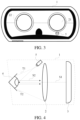
- the camera 5 since the eye 4 of the user is usually located at a center position of the convex lens 2 in the horizontal direction, the camera 5 may be located at the center position of the convex lens 2 in the horizontal direction as shown in FIG. 3 , thereby reducing the probability that the eye pattern features acquired by the camera 5 are deformed or distorted, or reducing the deformation or distortion on the eye pattern features.
- the VR helmet includes two convex lenses 2 corresponding to the eyes of the user.
- FIG. 3 shows a right convex lens 21 corresponding to a right eye of the user, and a left convex lens 22 corresponding to a left eye of the user.
- one or more cameras 5 can be provided.
- a camera 5 may be disposed only at the right convex lens 21 to acquire eye pattern features of the right eye of the user; similarly, a camera 5 may be disposed only at the left convex lens 22 to acquire eye pattern features of the left eye of the user.
- the cameras 5 may be disposed at the right convex lens 21 and the left convex lens 22 respectively to acquire eye pattern features of the right and left eyes of the user simultaneously or separately.
- the camera 5 is located at the bottom of the apparatus body 1 and below the convex lens 2, the camera 5 may be located at other positions, which is not limited in this application.
- the camera 5 may be disposed at the top of the apparatus body 1 and above the convex lens 2, such that the camera 5 tilts downward by a second preset angle, and the lens of the camera 5 faces the eye 4 of the user to achieve the acquisition of the eye pattern features.
- the camera 5 in the embodiment shown in FIG. 4 may also be electrically connected to the adjustment component 6 to achieve angular adjustment of the camera 5. Similar to the embodiment shown in FIG.
- the camera 5 in the embodiment shown in FIG. 4 may also be disposed at a center position of the corresponding convex lens 2 in the horizontal direction to reduce the probability that the eye pattern features acquired by the camera 5 are deformed or distorted, or reduce the deformation or distortion on the eye pattern features. Detail implementation will not be repeated here.
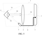
- FIG. 5 is a side cross-sectional view of a VR helmet as in the current invention.
- the VR helmet may be a split VR head-mounted apparatus, and an apparatus body 1 of the VR helmet is provided with an apparatus interface 7, so that the apparatus interface 7 is electrically connected to an electronic device such as a mobile phone or a tablet installed in the apparatus body 1.
- an electronic device such as a mobile phone or a tablet installed in the apparatus body 1.
- the electronic device may work as the VR playing component 3 in the apparatus body 1.
- the camera 5 in the apparatus body 1 is connected to the apparatus interface 7 through a data line 8, so that when the electronic device connected to the apparatus interface 7 issues a switch control instruction, the camera 5 receives the switch control instruction through the apparatus interface 7 and the data line 8 to perform a state switching operation in response to the switch control instruction.
- the electronic device by controlling the electronic device or an application program running on the electronic device, the electronic device sends a switch control instruction to the camera 5, thereby controlling the camera 5 to acquire the eye pattern features of the eye 4. That improves the controllability of the eye pattern features acquisition.
- the acquired eye pattern features may be transmitted to the processing module for processing.
- the camera 5 may transmit, through the apparatus interface 7 and the data line 8, the acquired eye pattern features to the foregoing electronic device for processing by the electronic device.
- the VR helmet of this application may include other forms of VR head-mounted apparatuses.
- the VR helmet may be paired with a PC host, a game console or another external apparatus.
- the VR playing component 3 may be a display component built into the VR helmet, etc., and the external apparatus is used for rendering of VR display content.
- the VR helmet may be an integrated VR head-mounted apparatus, that is, the VR helmet may independently implement a VR playing function without resorting to an external apparatus, the VR playing component 3 is build-in in the VR helmet.
- the VR playing component 3 may have playing functions such as rendering and displaying of VR content.
- first, second, and third may be used herein to describe various information, such information should not be limited to these terms. These terms are merely used for distinguishing information of the same type from each other.
- first information may also be referred to as second information, and similarly, second information may also be referred to as first information.
- second information may also be referred to as first information.
- if as used herein may be interpreted as "when " or “upon " or "in response to determining.”
Landscapes
- Physics & Mathematics (AREA)
- Engineering & Computer Science (AREA)
- General Physics & Mathematics (AREA)
- Optics & Photonics (AREA)
- Multimedia (AREA)
- Signal Processing (AREA)
- Theoretical Computer Science (AREA)
- General Engineering & Computer Science (AREA)
- Computer Security & Cryptography (AREA)
- Software Systems (AREA)
- Computer Hardware Design (AREA)
- Human Computer Interaction (AREA)
- User Interface Of Digital Computer (AREA)
- Measurement Of The Respiration, Hearing Ability, Form, And Blood Characteristics Of Living Organisms (AREA)
- Controls And Circuits For Display Device (AREA)
- Position Input By Displaying (AREA)
Description
- This application relates to the technical field of virtual reality, and in particular, to a virtual reality head-mounted apparatus.
- Virtual reality (VR) technology is a technology that comprehensively utilizes a computer graphics system and various control interfaces to generate an interactive three-dimensional interaction environment on a computer to provide users with immersive experience. In related art, a user may wear a virtual reality head-mounted apparatus, such as VR glasses or a VR helmet, to obtain corresponding virtual reality experience.
- However, due to unique characteristics of VR scenarios, technical solutions for traditional electronic devices such as mobile phones or PCs may not be applicable to VR scenarios. For example, to conduct identity verification of a user, processing methods based on password, gesture recognition, etc. in related art may cause an identity recognition process become too complicate and take too long to complete, if it can be completed at all.
-
US 2015009574 A1 discloses a HMD apparatus with an imaging optical system for each one of the eyes of a user, which includes at least one display unit to be viewed by the respective eye. -
WO2017026371 A1 andUS 2018/21821 Al describe a head-mounted display in which it is easy to photograph eyes of a user that wears the head-mounted display. -
US 2016/259986 A1 discloses a head mounted device (HMD) includes an imaging unit configured to capture at least one image of a partial region of an iris, an electrocardiogram (ECG) sensor configured to receive an ECG signal, and a control unit configured to acquire at least one image of the partial region of the iris and ECG signals, and authenticate a user by using the acquired image(s) of the partial region of the iris and the ECG signals. - Hayden Scott: "Hands On: SMIs Gear VR Eye Tracking is Accurate, Fast and Lightweight" (https:// www.roadtovr.com/hands-smis-gear-vr-eye-tracking-accurate-fast-lightweight) discloses a Samsung Gear VR Headset as a support for attaching a mobile phone and playing VR content but enhanced with "a small pair of cameras placed on either side of the headset" - part of the SMI eye tracking kit.
- Pupil Dev Team: "Blog - HTC Vive Eye Tracking Add On - Pupil Labs" (https://pupil-labs.com/blog/ news/htc-vive-eye-tracking-add-on) discloses the possibility of adding eye tracking to an existing HTC Vive HMD incorporating eye-facing cameras.
- The invention provides a virtual reality head-mounted apparatus as set out in the accompanying claims. Also disclosed herein is a virtual reality head-mounted apparatus, which can perform, by acquiring eye pattern features of a user, an identity recognition operation on the user wearing the virtual reality head-mounted apparatus quickly and accurately.
- To achieve the foregoing objective, this application provides advantageous embodiments in the dependent claims.
- This description also provides other aspects, as follows, that do not necessarily correspond to real realisations of the invention. The actual embodiments of the invention fall within the scope of the appended claims.
- A first aspect of this application is directed to a virtual reality head-mounted apparatus, including: an apparatus body, the apparatus body including a convex lens and a camera, the camera being located on a user side of the convex lens, and a lens of the camera facing an eye of the user to acquire eye pattern features of the user.
- Optionally, the camera is located below the convex lens, and the camera tilts upward by a first preset angle, so that the lens of the camera faces the eye of the user.
- Optionally, the camera is located above the convex lens, and the camera tilts downward by a second preset angle, so that the lens of the camera faces the eye of the user.
- Optionally, the camera is located at one of two convex lenses provided in the apparatus body for acquiring eye pattern features of the eye of the user corresponding to the one of the two convex lenses.
- Optionally, the apparatus body includes two cameras, respectively located at two convex lenses in the apparatus body for respectively acquiring eye pattern features of the eye of the user corresponding to each convex lens.
- Optionally, the camera is provided outside a visible area of the convex lens with respect to the user.
- Optionally, the camera is installed in a position in close contact with the corresponding convex lens.
- Optionally, the camera may be an RGB camera or an RGB-IR camera.
- In the current invention, the apparatus further includes:
- an apparatus interface provided on the apparatus body, the apparatus interface being capable of being electrically connected to an electronic device installed in the apparatus body, the electronic device being used to play virtual reality display content, and
- the camera being connected to the apparatus interface through a data line, wherein the camera is configured to, upon receiving a switch control instruction transmitted by the electronic device through the apparatus interface and the data line, perform a state switching operation in response to the switch control instruction, and transmit the acquired eye pattern features to the electronic device through the apparatus interface and the data line.
- Optionally, the apparatus further includes:
an adjustment component, the adjustment component being capable of performing angle adjustment on the camera, such that the lens of the camera tilts toward the eye of the user. - As can be seen from the above technical solutions, in this application, a camera is provided in an apparatus body of the virtual reality head-mounted apparatus, and a lens of the camera faces an eye of a user, so that eye pattern features of the user can be acquired by the camera without interfering with the user's viewing of virtual reality display content. Identity information of the user may be efficiently and quickly verified by comparing and identifying the eye pattern features, thereby improving the security of the virtual reality head-mounted apparatus.
-
-
FIG. 1 is a side cross-sectional view of a VR helmet provided by a first exemplary embodiment of this application. -
FIG. 2 is a side cross-sectional view of a VR helmet provided by a second exemplary embodiment of this application. -
FIG. 3 is a structural diagram of a VR helmet in a wearer direction provided by an exemplary embodiment of this application. -
FIG. 4 is a side cross-sectional view of a VR helmet provided by a third exemplary embodiment of this application. -
FIG. 5 is a side cross-sectional view of a VR helmet provided by a fourth exemplary embodiment of this application. - In order to further explain this application, the following embodiments are provided, using a VR helmet as an example, to introduce the related structure of a virtual reality head-mounted apparatus of this application.
-
FIG. 1 is a side cross-sectional view of a VR helmet provided by an exemplary embodiment of this application. As shown inFIG. 1 , aconvex lens 2 and aVR playing component 3 are provided in anapparatus body 1 of a VR helmet. Theconvex lens 2 is located between a user (FIG. 1 shows aneye 4 of the user) and theVR playing component 3 in theapparatus body 1, so that VR display content played by theVR playing component 3 may, in a form of visible light S1, go through theconvex lens 2 and propagate to theeye 4 of the user. Theeye 4 of the user receives the visible light S1 for viewing the VR display content. - Additionally, the
apparatus body 1 may be provided with acamera 5. Thecamera 5 is located on a user side (i.e., a left side in the embodiment shown inFIG. 1 ) of theconvex lens 2, and a lens of thecamera 5 faces aneye 4 of the user for acquiring eye pattern features of the user. Identity recognition on a user wearing the VR helmet may be performed by comparing and matching the eye pattern features. Compared with an identity recognition scheme based on password, gesture recognition, etc. in related art, this application can acquire and recognize eye pattern features of users by thecamera 5 installed in the VR helmet, which does not require any complicated structures and devices, and does not require users to perform separate and additional operations. That improves the efficiency of identity recognition and simplifies user operations. Thecamera 5 may be an infrared radiation (IR) camera or an integrated red-green-blue (RGB)-IR camera, which is not limited in this application. - In the foregoing embodiment, in order to avoid blocking the VR display content played by the
VR playing component 3, that is, to avoid blocking the propagation of the visible light S1, thecamera 5 needs to be placed outside of a visible area of theconvex lens 2 with respect to theeye 4 of the user (for example, the visible area may be indicated by an upper boundary T1 and a lower boundary T2 as shown inFIG. 1 ). Thecamera 5 may be provided at the bottom of theapparatus body 1, that is, thecamera 5 is located below theconvex lens 2. Thecamera 5 may tilt upward by a first preset angle, so that the lens of thecamera 5 faces theeye 4 of the user. - While using the VR helmet, a user may maintain his/her
eye 4 in a straight-looking state as shown inFIG. 1 , thus the light S2 from theeye 4 may propagate substantially horizontally, and a line between thecamera 5 and theeye 4 may form an angle α with the light S2. Then, in order to avoid the severe deformation of the acquired eye pattern features when the angle α is too large, thecamera 5 may be disposed in close contact with an edge of the convex lens 2 (in term of at least one of a horizontal distance and a vertical distance). That is, the distance between thecamera 5 and the eye 4 (in term of at least one of the horizontal distance and the vertical distance) is maximized to keep the angle α as small as possible. - Additionally, as shown in
FIG. 2 , the VR helmet may include anadjustment component 6, and theadjustment component 6 is electrically connected to thecamera 5, so that when different users use the same VR helmet, theadjustment component 6 can adjust the angle of thecamera 5 to ensure that the lens of thecamera 5 faces theeye 4 of the user, thereby avoiding the distortion of the acquired eye pattern features. - In the foregoing embodiment, as shown in
FIG. 1 , although in a vertical direction, in order to avoid blocking thevisible light S 1, thecamera 5 has to be located outside the visible area and cannot be at the same height as theeye 4, but in a horizontal direction, a horizontal angle between the lens of thecamera 5 and the light S2 can be minimized, if not eliminated. For example, since theeye 4 of the user is usually located at a center position of theconvex lens 2 in the horizontal direction, thecamera 5 may be located at the center position of theconvex lens 2 in the horizontal direction as shown inFIG. 3 , thereby reducing the probability that the eye pattern features acquired by thecamera 5 are deformed or distorted, or reducing the deformation or distortion on the eye pattern features. - In the foregoing embodiment, the VR helmet includes two
convex lenses 2 corresponding to the eyes of the user. For example,FIG. 3 shows a rightconvex lens 21 corresponding to a right eye of the user, and a leftconvex lens 22 corresponding to a left eye of the user. Depending on actual requirements, one ormore cameras 5 can be provided. For example, as shown inFIG. 3 , acamera 5 may be disposed only at the rightconvex lens 21 to acquire eye pattern features of the right eye of the user; similarly, acamera 5 may be disposed only at the leftconvex lens 22 to acquire eye pattern features of the left eye of the user. Certainly, thecameras 5 may be disposed at the rightconvex lens 21 and the leftconvex lens 22 respectively to acquire eye pattern features of the right and left eyes of the user simultaneously or separately. - Certainly, although in the embodiment shown in
FIGS. 1-3 , thecamera 5 is located at the bottom of theapparatus body 1 and below theconvex lens 2, thecamera 5 may be located at other positions, which is not limited in this application. For example, as shown inFIG. 4 , thecamera 5 may be disposed at the top of theapparatus body 1 and above theconvex lens 2, such that thecamera 5 tilts downward by a second preset angle, and the lens of thecamera 5 faces theeye 4 of the user to achieve the acquisition of the eye pattern features. Similar to the embodiment shown inFIG. 2 , thecamera 5 in the embodiment shown inFIG. 4 may also be electrically connected to theadjustment component 6 to achieve angular adjustment of thecamera 5. Similar to the embodiment shown inFIG. 3 , thecamera 5 in the embodiment shown inFIG. 4 may also be disposed at a center position of the correspondingconvex lens 2 in the horizontal direction to reduce the probability that the eye pattern features acquired by thecamera 5 are deformed or distorted, or reduce the deformation or distortion on the eye pattern features. Detail implementation will not be repeated here. -
FIG. 5 is a side cross-sectional view of a VR helmet as in the current invention. As shown inFIG. 5 , the VR helmet may be a split VR head-mounted apparatus, and anapparatus body 1 of the VR helmet is provided with anapparatus interface 7, so that theapparatus interface 7 is electrically connected to an electronic device such as a mobile phone or a tablet installed in theapparatus body 1. By using a processor and a graphic card for rendering, a screen component for displaying, the electronic device may work as theVR playing component 3 in theapparatus body 1. - Additionally, the
camera 5 in theapparatus body 1 is connected to theapparatus interface 7 through adata line 8, so that when the electronic device connected to theapparatus interface 7 issues a switch control instruction, thecamera 5 receives the switch control instruction through theapparatus interface 7 and thedata line 8 to perform a state switching operation in response to the switch control instruction. In other words, by controlling the electronic device or an application program running on the electronic device, the electronic device sends a switch control instruction to thecamera 5, thereby controlling thecamera 5 to acquire the eye pattern features of theeye 4. That improves the controllability of the eye pattern features acquisition. - In addition, after the
camera 5 completes the acquisition of the eye pattern features, if the VR helmet is provided with a processing module, the acquired eye pattern features may be transmitted to the processing module for processing. Alternatively, thecamera 5 may transmit, through theapparatus interface 7 and thedata line 8, the acquired eye pattern features to the foregoing electronic device for processing by the electronic device. - Other than a split VR head-mounted apparatus matched with an electronic device such as a mobile phone, the VR helmet of this application may include other forms of VR head-mounted apparatuses. For example, for the split VR head-mounted apparatus, the VR helmet may be paired with a PC host, a game console or another external apparatus. The
VR playing component 3 may be a display component built into the VR helmet, etc., and the external apparatus is used for rendering of VR display content. For another example, when the VR helmet may be an integrated VR head-mounted apparatus, that is, the VR helmet may independently implement a VR playing function without resorting to an external apparatus, theVR playing component 3 is build-in in the VR helmet. TheVR playing component 3 may have playing functions such as rendering and displaying of VR content. - It should also be noted that the terms "include", "comprise" and any other variants mean to cover the non-exclusive inclusion. Thereby, the process, method, article, or device which include a series of elements not only include those elements, but also include other elements which are not clearly listed, or include the inherent elements of the process, method, article and device. Without further limitation, the element defined by a phrase "include one..." does not exclude other same elements in the process, method, article or device which include the element.
- Reference is made in detail to exemplary embodiments, examples of which are illustrated in the accompanying drawings. The above description refers to the accompanying drawings in which the same numbers in different drawings represent the same or similar elements unless otherwise represented. The implementations set forth in the above description of exemplary embodiments do not represent all implementations consistent with this application. Instead, they are merely examples of apparatuses and methods consistent with aspects related to this application as recited in the appended claims.
- The terms used in this application are merely for the purpose of describing specific embodiments, and are not intended to limit this application. The terms "a", "said" and "the" of singular forms used in this application and the appended claims are also intended to include plural forms, unless otherwise specified in the context clearly. It should also be understood that, the term "and/or" used herein indicates and includes any or all possible combinations of one or more associated listed items.
- It should be understood that although the terms such as first, second, and third may be used herein to describe various information, such information should not be limited to these terms. These terms are merely used for distinguishing information of the same type from each other. For example, within the scope of this application, first information may also be referred to as second information, and similarly, second information may also be referred to as first information. Depending on the context, the term "if" as used herein may be interpreted as "when ..." or "upon ..." or "in response to determining."
Claims (9)
- A virtual reality head-mounted apparatus, comprising:
an apparatus body (1), the apparatus body (1) comprising a convex lens and a camera (5), and an apparatus interface (7), the camera (5) being located on a user side of the convex lens (2), and a lens of the camera (5) directly facing an eye of the user to acquire eye pattern features of the user,wherein the apparatus interface (7) is provided on the apparatus body on a side of the convex lens (2) away from the user, the apparatus interface (7) being capable of being electrically connected to an electronic device installed in the apparatus body (1), the electronic device being a mobile phone or tablet used to play virtual reality display content,the camera being connected to the apparatus interface (7) through a data line (8), wherein the camera is configured to, upon receiving a control instruction transmitted by the electronic device through the apparatus interface (7) and the data line (8), perform an operation to acquire the eye pattern features in response to the control instruction, and transmit the acquired eye pattern features to the electronic device through the apparatus interface (7) and the data line (8), the electronic device being configured to acquire the eye pattern features while the user is watching the virtual reality display content through the convex lens and to process the acquired eye pattern features to perform an identity verification operation on the user. - The apparatus according to claim 1, wherein the camera (5) is located below the convex lens (2), and the camera (5) tilts upward by a first preset angle, so that the lens of the camera (5) faces the eye of the user.
- The apparatus according to claim 1, wherein the camera (5) is located above the convex lens (2), and the camera (5) tilts downward by a second preset angle, so that the lens of the camera (5) faces the eye of the user.
- The apparatus according to claim 1, wherein the camera (5) is located at one of two convex lenses provided in the apparatus body (1) for acquiring eye pattern features of the eye of the user corresponding to the one of the two convex lenses.
- The apparatus according to claim 1, wherein the apparatus body (1) comprises two cameras, respectively located at two convex lenses in the apparatus body (1) for respectively acquiring eye pattern features of the eye of the user corresponding to each convex lens.
- The apparatus according to claim 1, wherein the camera (5) is provided outside a visible area of the convex lens with respect to the user.
- The apparatus according to claim 1, wherein the camera (5) is installed at a position in close contact with the corresponding convex lens.
- The apparatus according to claim 1, wherein the camera (5) is an RGB camera or an RGB-IR camera.
- The apparatus according to claim 1, further comprising:
an adjustment component, the adjustment component being capable of performing angle adjustment on the camera (5), such that the lens of the camera (5) tilts toward the eye of the user.
Applications Claiming Priority (2)
| Application Number | Priority Date | Filing Date | Title |
|---|---|---|---|
| CN201710109091.6A CN106873159A (en) | 2017-02-27 | 2017-02-27 | Virtual reality helmet |
| PCT/CN2018/077280 WO2018153367A1 (en) | 2017-02-27 | 2018-02-26 | Virtual reality head-mounted apparatus |
Publications (4)
| Publication Number | Publication Date |
|---|---|
| EP3567413A1 EP3567413A1 (en) | 2019-11-13 |
| EP3567413A4 EP3567413A4 (en) | 2019-12-18 |
| EP3567413B1 true EP3567413B1 (en) | 2025-05-21 |
| EP3567413C0 EP3567413C0 (en) | 2025-05-21 |
Family
ID=59167914
Family Applications (1)
| Application Number | Title | Priority Date | Filing Date |
|---|---|---|---|
| EP18757692.1A Active EP3567413B1 (en) | 2017-02-27 | 2018-02-26 | Virtual reality head-mounted apparatus |
Country Status (10)
| Country | Link |
|---|---|
| US (1) | US11523039B2 (en) |
| EP (1) | EP3567413B1 (en) |
| JP (1) | JP7071384B2 (en) |
| KR (1) | KR20190105644A (en) |
| CN (1) | CN106873159A (en) |
| MY (1) | MY207480A (en) |
| PH (1) | PH12019501869A1 (en) |
| SG (1) | SG11201907256QA (en) |
| TW (1) | TWI664444B (en) |
| WO (1) | WO2018153367A1 (en) |
Families Citing this family (9)
| Publication number | Priority date | Publication date | Assignee | Title |
|---|---|---|---|---|
| CN106980983A (en) * | 2017-02-23 | 2017-07-25 | 阿里巴巴集团控股有限公司 | Service authentication method and device based on virtual reality scenario |
| CN106873159A (en) * | 2017-02-27 | 2017-06-20 | 阿里巴巴集团控股有限公司 | Virtual reality helmet |
| CN107238930A (en) * | 2017-07-19 | 2017-10-10 | 北京小米移动软件有限公司 | Virtual reality glasses |
| CN109685909B (en) * | 2018-11-12 | 2022-12-20 | 腾讯科技(深圳)有限公司 | Image display method, image display device, storage medium and electronic device |
| CN112190227B (en) * | 2020-10-14 | 2022-01-11 | 北京鹰瞳科技发展股份有限公司 | Fundus camera and its use state detection method |
| FR3116919A1 (en) * | 2020-11-30 | 2022-06-03 | Orange | Device and method for authenticating a user of a virtual reality headset |
| CN112987269B (en) * | 2021-03-03 | 2022-10-25 | 北京航空航天大学 | A wearable eye pattern (scleral blood vessel) imaging device based on microlens array |
| CN113670232B (en) * | 2021-08-18 | 2024-06-25 | 歌尔光学科技有限公司 | Eccentric standard sample of virtual reality equipment and measuring method of eccentric value of standard sample |
| CN115857164A (en) * | 2022-12-01 | 2023-03-28 | 富泰华工业(深圳)有限公司 | Near-to-eye display device and near-to-eye display device visual angle adjusting method |
Family Cites Families (66)
| Publication number | Priority date | Publication date | Assignee | Title |
|---|---|---|---|---|
| JP3571501B2 (en) | 1997-07-28 | 2004-09-29 | コニカミノルタホールディングス株式会社 | Video observation device |
| US20060017654A1 (en) | 2004-07-23 | 2006-01-26 | Romo Justin R | Virtual reality interactivity system and method |
| US9649551B2 (en) | 2008-06-03 | 2017-05-16 | Tweedletech, Llc | Furniture and building structures comprising sensors for determining the position of one or more objects |
| JP2011069978A (en) | 2009-09-25 | 2011-04-07 | Brother Industries Ltd | Retina scanning type image display device |
| JP2012168346A (en) | 2011-02-15 | 2012-09-06 | Casio Comput Co Ltd | Browsing device |
| EP2499964B1 (en) | 2011-03-18 | 2015-04-15 | SensoMotoric Instruments Gesellschaft für innovative Sensorik mbH | Optical measuring device and system |
| CN103380625A (en) | 2011-06-16 | 2013-10-30 | 松下电器产业株式会社 | Head-mounted display and its position deviation adjustment method |
| US9316834B2 (en) | 2011-11-24 | 2016-04-19 | Panasonic Intellectual Property Management Co., Ltd. | Head-mounted display device with foveated pixels |
| US9671566B2 (en) | 2012-06-11 | 2017-06-06 | Magic Leap, Inc. | Planar waveguide apparatus with diffraction element(s) and system employing same |
| US9788714B2 (en) | 2014-07-08 | 2017-10-17 | Iarmourholdings, Inc. | Systems and methods using virtual reality or augmented reality environments for the measurement and/or improvement of human vestibulo-ocular performance |
| JP6094305B2 (en) | 2013-03-26 | 2017-03-15 | セイコーエプソン株式会社 | Head-mounted display device and method for controlling head-mounted display device |
| TWI507762B (en) | 2013-05-31 | 2015-11-11 | Pixart Imaging Inc | Eye tracking device and optical assembly thereof |
| GB201310359D0 (en) * | 2013-06-11 | 2013-07-24 | Sony Comp Entertainment Europe | Head-Mountable apparatus and systems |
| EP2821839A1 (en) * | 2013-07-03 | 2015-01-07 | Airbus Defence and Space GmbH | HMD device with adjustable eye tracking device |
| US10073518B2 (en) * | 2013-08-19 | 2018-09-11 | Qualcomm Incorporated | Automatic calibration of eye tracking for optical see-through head mounted display |
| GB201314984D0 (en) * | 2013-08-21 | 2013-10-02 | Sony Comp Entertainment Europe | Head-mountable apparatus and systems |
| US20150070489A1 (en) * | 2013-09-11 | 2015-03-12 | Microsoft Corporation | Optical modules for use with depth cameras |
| US9459451B2 (en) * | 2013-12-26 | 2016-10-04 | Microsoft Technology Licensing, Llc | Eye tracking apparatus, method and system |
| US9594246B2 (en) * | 2014-01-21 | 2017-03-14 | Osterhout Group, Inc. | See-through computer display systems |
| US9829707B2 (en) * | 2014-08-12 | 2017-11-28 | Osterhout Group, Inc. | Measuring content brightness in head worn computing |
| WO2015134953A1 (en) | 2014-03-06 | 2015-09-11 | Virtual Reality Medical Applications, Inc. | Virtual reality medical application system |
| WO2016018488A2 (en) | 2014-05-09 | 2016-02-04 | Eyefluence, Inc. | Systems and methods for discerning eye signals and continuous biometric identification |
| CN204129314U (en) * | 2014-05-22 | 2015-01-28 | 宁波舜宇光电信息有限公司 | A kind of videography optical lens group and iris camera module |
| CN106797423B (en) | 2014-06-27 | 2019-12-06 | Fove股份有限公司 | Sight line detection device |
| US9420075B2 (en) * | 2014-07-16 | 2016-08-16 | DODOcase, Inc. | Virtual reality viewer and input mechanism |
| KR102244222B1 (en) | 2014-09-02 | 2021-04-26 | 삼성전자주식회사 | A method for providing a visual reality service and apparatuses therefor |
| US9699436B2 (en) | 2014-09-16 | 2017-07-04 | Microsoft Technology Licensing, Llc | Display with eye-discomfort reduction |
| JP6501389B2 (en) | 2014-12-01 | 2019-04-17 | 浅田 一憲 | Head mounted display device, photographing control method, and program |
| US9791924B2 (en) * | 2014-12-23 | 2017-10-17 | Mediatek Inc. | Eye tracking with mobile device in a head-mounted display |
| DK179537B1 (en) * | 2015-02-04 | 2019-02-08 | Itu Business Development A/S | Tin traces and eye tracking methods |
| US10055887B1 (en) * | 2015-02-19 | 2018-08-21 | Google Llc | Virtual/augmented reality transition system and method |
| US9836663B2 (en) * | 2015-03-05 | 2017-12-05 | Samsung Electronics Co., Ltd. | User authenticating method and head mounted device supporting the same |
| US10102674B2 (en) * | 2015-03-09 | 2018-10-16 | Google Llc | Virtual reality headset connected to a mobile computing device |
| CN104793741A (en) | 2015-04-03 | 2015-07-22 | 深圳市虚拟现实科技有限公司 | Imaging system and method for guiding eyeballs to trace virtual reality |
| CN104834852B (en) | 2015-05-04 | 2018-07-13 | 惠州Tcl移动通信有限公司 | A kind of method and system that mobile terminal is unlocked based on high quality eyeprint image |
| US20160358181A1 (en) * | 2015-05-14 | 2016-12-08 | Magic Leap, Inc. | Augmented reality systems and methods for tracking biometric data |
| WO2016191709A1 (en) | 2015-05-28 | 2016-12-01 | Thalmic Labs Inc. | Systems, devices, and methods that integrate eye tracking and scanning laser projection in wearable heads-up displays |
| US9857595B2 (en) * | 2015-07-31 | 2018-01-02 | Google Llc | Integrated mobile device shipping container and virtual reality headset |
| CN105068249A (en) | 2015-08-03 | 2015-11-18 | 众景视界(北京)科技有限公司 | Holographic intelligent glasses |
| CN107852474B (en) * | 2015-08-11 | 2021-01-08 | 索尼互动娱乐股份有限公司 | Head-mounted display |
| KR102433833B1 (en) | 2015-09-23 | 2022-08-17 | 매직 립, 인코포레이티드 | Eye Imaging with Off-Axis Imager |
| DE102015219859B4 (en) * | 2015-10-13 | 2017-07-27 | Carl Zeiss Vision International Gmbh | Apparatus and method for AR display |
| CN105212418A (en) | 2015-11-05 | 2016-01-06 | 北京航天泰坦科技股份有限公司 | Augmented reality intelligent helmet based on infrared night viewing function is developed |
| WO2017079689A1 (en) | 2015-11-06 | 2017-05-11 | Oculus Vr, Llc | Eye tracking using optical flow |
| CN105653227A (en) * | 2016-03-22 | 2016-06-08 | 北京全景思维科技有限公司 | Head-mounted virtual reality display device and method for tracking focal length of eyeballs |
| CN205594581U (en) | 2016-04-06 | 2016-09-21 | 北京七鑫易维信息技术有限公司 | Module is tracked to eyeball of video glasses |
| CN106406509B (en) | 2016-05-16 | 2023-08-01 | 上海青研科技有限公司 | Head-mounted eye-control virtual reality equipment |
| CN205844631U (en) * | 2016-06-07 | 2016-12-28 | 腾讯科技(深圳)有限公司 | A kind of virtual reality glasses and display device thereof |
| CN105955491B (en) * | 2016-06-30 | 2020-07-10 | 北京上古视觉科技有限公司 | VR glasses with eye accuse and iris recognition function |
| CN205942609U (en) * | 2016-06-30 | 2017-02-08 | 北京上古视觉科技有限公司 | VR glasses with eye accuse and iris recognition function |
| CN107562179B (en) | 2016-06-30 | 2024-04-26 | 上海青研科技有限公司 | Integrated mirror cup for eyeball tracking and iris recognition |
| CN205942608U (en) * | 2016-06-30 | 2017-02-08 | 上海青研科技有限公司 | A integration mirror cup that is used for eyeball to track and iris discernment |
| CN106155326A (en) * | 2016-07-26 | 2016-11-23 | 北京小米移动软件有限公司 | Object identifying method in virtual reality communication and device, virtual reality device |
| US10409368B2 (en) * | 2016-07-27 | 2019-09-10 | Fove, Inc. | Eye-gaze detection system, displacement detection method, and displacement detection program |
| DE202016104179U1 (en) * | 2016-07-29 | 2016-08-12 | Christian Hildebrandt | Output device for stereoscopic image reproduction |
| CN110059585B (en) | 2016-08-18 | 2023-10-24 | 瑞声光学解决方案私人有限公司 | Virtual reality equipment with iris acquisition function |
| CN106250749A (en) | 2016-08-25 | 2016-12-21 | 安徽协创物联网技术有限公司 | A kind of virtual reality intersection control routine |
| CN106339087B (en) | 2016-08-29 | 2019-01-29 | 上海青研科技有限公司 | A kind of eyeball tracking method and device thereof based on multidimensional coordinate |
| CN106203410B (en) | 2016-09-21 | 2023-10-17 | 上海星寰投资有限公司 | Identity verification method and system |
| EP4468061A3 (en) | 2016-10-05 | 2025-01-15 | Magic Leap, Inc. | Periocular test for mixed reality calibration |
| KR102773928B1 (en) * | 2016-11-04 | 2025-03-04 | 삼성전자주식회사 | Method and device for acquiring information by capturing eye |
| CN206249347U (en) | 2016-11-18 | 2017-06-13 | 南京中科道置智能科技有限公司 | A kind of iris identification device in virtual reality glasses |
| US10310598B2 (en) * | 2017-01-17 | 2019-06-04 | Facebook Technologies, Llc | Varifocal head-mounted display including modular air spaced optical assembly |
| CN206584119U (en) * | 2017-02-27 | 2017-10-24 | 阿里巴巴集团控股有限公司 | Virtual reality helmet |
| CN106873159A (en) * | 2017-02-27 | 2017-06-20 | 阿里巴巴集团控股有限公司 | Virtual reality helmet |
| US10488917B2 (en) * | 2018-02-17 | 2019-11-26 | Varjo Technologies Oy | Gaze-tracking system and method of tracking user's gaze using reflective element |
-
2017
- 2017-02-27 CN CN201710109091.6A patent/CN106873159A/en active Pending
- 2017-11-20 TW TW106140067A patent/TWI664444B/en active
-
2018
- 2018-02-26 WO PCT/CN2018/077280 patent/WO2018153367A1/en not_active Ceased
- 2018-02-26 KR KR1020197024490A patent/KR20190105644A/en not_active Ceased
- 2018-02-26 MY MYPI2019004410A patent/MY207480A/en unknown
- 2018-02-26 SG SG11201907256QA patent/SG11201907256QA/en unknown
- 2018-02-26 JP JP2019546342A patent/JP7071384B2/en active Active
- 2018-02-26 EP EP18757692.1A patent/EP3567413B1/en active Active
-
2019
- 2019-07-31 US US16/527,978 patent/US11523039B2/en active Active
- 2019-08-13 PH PH12019501869A patent/PH12019501869A1/en unknown
Non-Patent Citations (7)
| Title |
|---|
| ANTHES CHRISTOPH ET AL: "State of the art of virtual reality technology", 2016 IEEE AEROSPACE CONFERENCE, IEEE, 5 March 2016 (2016-03-05), pages 1 - 19, XP032916463, DOI: 10.1109/AERO.2016.7500674 * |
| HAYDEN SCOTT: "Hands On: SMIs Gear VR Eye Tracking is Accurate, Fast and Lightweight", 24 February 2016 (2016-02-24), pages 1 - 4, XP055804523, Retrieved from the Internet <URL:https://www.roadtovr.com/hands-smis-gear-vr-eye-tracking-accurate-fast-lightweight/> [retrieved on 20210516] * |
| PUPIL DEV TEAM: "Blog - HTC Vive Eye Tracking Add On - Pupil Labs", 9 August 2016 (2016-08-09), pages 1 - 1, XP055946503, Retrieved from the Internet <URL:https://pupil-labs.com/blog/news/htc-vive-eye-tracking-add-on/> [retrieved on 20220726] * |
| PUPIL LABS: "Closeup of the add-on engagement with the lens holder.", 14 October 2016 (2016-10-14), XP055946478, Retrieved from the Internet <URL:https://www.youtube.com/watch?v=zswmKmIBrss> [retrieved on 20220726] * |
| PUPIL LABS: "TAKE HTC Vive apart a bit more so we can show a close up view", 14 October 2016 (2016-10-14), XP055946480, Retrieved from the Internet <URL:https://www.youtube.com/watch?v=nIzuwHagIXQ> [retrieved on 20220726] * |
| PUPIL LABS: "Unbox the Pupil Labs add-on", 14 October 2016 (2016-10-14), XP055946479, Retrieved from the Internet <URL:https://www.youtube.com/watch?v=HGMjJLnK2_4> [retrieved on 20220726] * |
| SCOTT W GREENWALD ET AL: "Eye gaze tracking with google cardboard using purkinje images", PROCEEDINGS OF THE 22ND ACM CONFERENCE ON VIRTUAL REALITY SOFTWARE AND TECHNOLOGY , VRST '16, ACM PRESS, NEW YORK, NEW YORK, USA, 2 November 2016 (2016-11-02), pages 19 - 22, XP058307017, ISBN: 978-1-4503-4491-3, DOI: 10.1145/2993369.2993407 * |
Also Published As
| Publication number | Publication date |
|---|---|
| EP3567413A4 (en) | 2019-12-18 |
| CN106873159A (en) | 2017-06-20 |
| EP3567413A1 (en) | 2019-11-13 |
| JP2020518842A (en) | 2020-06-25 |
| TW201831952A (en) | 2018-09-01 |
| KR20190105644A (en) | 2019-09-17 |
| WO2018153367A1 (en) | 2018-08-30 |
| JP7071384B2 (en) | 2022-05-18 |
| MY207480A (en) | 2025-02-28 |
| PH12019501869A1 (en) | 2020-06-08 |
| TWI664444B (en) | 2019-07-01 |
| US11523039B2 (en) | 2022-12-06 |
| SG11201907256QA (en) | 2019-09-27 |
| US20190354758A1 (en) | 2019-11-21 |
| EP3567413C0 (en) | 2025-05-21 |
Similar Documents
| Publication | Publication Date | Title |
|---|---|---|
| EP3567413B1 (en) | Virtual reality head-mounted apparatus | |
| US11500607B2 (en) | Using detected pupil location to align optical components of a head-mounted display | |
| EP3602399B1 (en) | Accumulation and confidence assignment of iris codes | |
| EP3564731B1 (en) | Virtual reality head-mounted apparatus | |
| US9377869B2 (en) | Unlocking a head mountable device | |
| EP3561573A1 (en) | Virtual reality head-mounted apparatus | |
| EP3714318B1 (en) | Position tracking system for head-mounted displays that includes sensor integrated circuits | |
| EP3557308B1 (en) | Virtual reality head-mounted apparatus | |
| JP2017009777A (en) | Display device, control method of display device, display system and program | |
| WO2022245629A1 (en) | Contextual visual and voice search from electronic eyewear device | |
| KR102614047B1 (en) | Electronic apparatus comprising flexible display | |
| CN206584117U (en) | Virtual reality helmet | |
| CN206584119U (en) | Virtual reality helmet | |
| EP4546841A1 (en) | Method for connecting to external display device on basis of biometric information, and electronic device | |
| HK1237883A1 (en) | Virtual reality head-mounted device | |
| HK1237883A (en) | Virtual reality head-mounted device | |
| KR20240014988A (en) | Electronic device and method for connecting with external display device based on biometric information | |
| HK1237882A1 (en) | Virtual reality head-mounted device | |
| HK1238726A (en) | Virtual reality head-mounted device | |
| HK1238726A1 (en) | Virtual reality head-mounted device |
Legal Events
| Date | Code | Title | Description |
|---|---|---|---|
| STAA | Information on the status of an ep patent application or granted ep patent |
Free format text: STATUS: THE INTERNATIONAL PUBLICATION HAS BEEN MADE |
|
| PUAI | Public reference made under article 153(3) epc to a published international application that has entered the european phase |
Free format text: ORIGINAL CODE: 0009012 |
|
| STAA | Information on the status of an ep patent application or granted ep patent |
Free format text: STATUS: REQUEST FOR EXAMINATION WAS MADE |
|
| 17P | Request for examination filed |
Effective date: 20190805 |
|
| AK | Designated contracting states |
Kind code of ref document: A1 Designated state(s): AL AT BE BG CH CY CZ DE DK EE ES FI FR GB GR HR HU IE IS IT LI LT LU LV MC MK MT NL NO PL PT RO RS SE SI SK SM TR |
|
| AX | Request for extension of the european patent |
Extension state: BA ME |
|
| STAA | Information on the status of an ep patent application or granted ep patent |
Free format text: STATUS: EXAMINATION IS IN PROGRESS |
|
| A4 | Supplementary search report drawn up and despatched |
Effective date: 20191119 |
|
| RIC1 | Information provided on ipc code assigned before grant |
Ipc: G06F 3/01 20060101ALI20191113BHEP Ipc: G06F 21/32 20130101ALI20191113BHEP Ipc: G02B 27/01 20060101AFI20191113BHEP |
|
| 17Q | First examination report despatched |
Effective date: 20191129 |
|
| DAV | Request for validation of the european patent (deleted) | ||
| DAX | Request for extension of the european patent (deleted) | ||
| RAP1 | Party data changed (applicant data changed or rights of an application transferred) |
Owner name: ADVANCED NEW TECHNOLOGIES CO., LTD. |
|
| GRAP | Despatch of communication of intention to grant a patent |
Free format text: ORIGINAL CODE: EPIDOSNIGR1 |
|
| STAA | Information on the status of an ep patent application or granted ep patent |
Free format text: STATUS: GRANT OF PATENT IS INTENDED |
|
| RIC1 | Information provided on ipc code assigned before grant |
Ipc: H04N 23/11 20230101ALI20241211BHEP Ipc: G06F 3/01 20060101ALI20241211BHEP Ipc: G02B 27/00 20060101ALI20241211BHEP Ipc: G06F 21/32 20130101ALI20241211BHEP Ipc: G02B 27/01 20060101AFI20241211BHEP |
|
| INTG | Intention to grant announced |
Effective date: 20241223 |
|
| GRAS | Grant fee paid |
Free format text: ORIGINAL CODE: EPIDOSNIGR3 |
|
| GRAA | (expected) grant |
Free format text: ORIGINAL CODE: 0009210 |
|
| STAA | Information on the status of an ep patent application or granted ep patent |
Free format text: STATUS: THE PATENT HAS BEEN GRANTED |
|
| AK | Designated contracting states |
Kind code of ref document: B1 Designated state(s): AL AT BE BG CH CY CZ DE DK EE ES FI FR GB GR HR HU IE IS IT LI LT LU LV MC MK MT NL NO PL PT RO RS SE SI SK SM TR |
|
| REG | Reference to a national code |
Ref country code: GB Ref legal event code: FG4D |
|
| REG | Reference to a national code |
Ref country code: CH Ref legal event code: EP |
|
| REG | Reference to a national code |
Ref country code: DE Ref legal event code: R096 Ref document number: 602018082098 Country of ref document: DE |
|
| REG | Reference to a national code |
Ref country code: IE Ref legal event code: FG4D |
|
| U01 | Request for unitary effect filed |
Effective date: 20250609 |
|
| U07 | Unitary effect registered |
Designated state(s): AT BE BG DE DK EE FI FR IT LT LU LV MT NL PT RO SE SI Effective date: 20250616 |
|
| P04 | Withdrawal of opt-out of the competence of the unified patent court (upc) registered |
Free format text: CASE NUMBER: APP_28073/2025 Effective date: 20250611 |
|
| PG25 | Lapsed in a contracting state [announced via postgrant information from national office to epo] |
Ref country code: ES Free format text: LAPSE BECAUSE OF FAILURE TO SUBMIT A TRANSLATION OF THE DESCRIPTION OR TO PAY THE FEE WITHIN THE PRESCRIBED TIME-LIMIT Effective date: 20250521 |
|
| PG25 | Lapsed in a contracting state [announced via postgrant information from national office to epo] |
Ref country code: GR Free format text: LAPSE BECAUSE OF FAILURE TO SUBMIT A TRANSLATION OF THE DESCRIPTION OR TO PAY THE FEE WITHIN THE PRESCRIBED TIME-LIMIT Effective date: 20250822 Ref country code: NO Free format text: LAPSE BECAUSE OF FAILURE TO SUBMIT A TRANSLATION OF THE DESCRIPTION OR TO PAY THE FEE WITHIN THE PRESCRIBED TIME-LIMIT Effective date: 20250821 |
|
| PG25 | Lapsed in a contracting state [announced via postgrant information from national office to epo] |
Ref country code: PL Free format text: LAPSE BECAUSE OF FAILURE TO SUBMIT A TRANSLATION OF THE DESCRIPTION OR TO PAY THE FEE WITHIN THE PRESCRIBED TIME-LIMIT Effective date: 20250521 |
|
| PG25 | Lapsed in a contracting state [announced via postgrant information from national office to epo] |
Ref country code: HR Free format text: LAPSE BECAUSE OF FAILURE TO SUBMIT A TRANSLATION OF THE DESCRIPTION OR TO PAY THE FEE WITHIN THE PRESCRIBED TIME-LIMIT Effective date: 20250521 |
|
| PG25 | Lapsed in a contracting state [announced via postgrant information from national office to epo] |
Ref country code: RS Free format text: LAPSE BECAUSE OF FAILURE TO SUBMIT A TRANSLATION OF THE DESCRIPTION OR TO PAY THE FEE WITHIN THE PRESCRIBED TIME-LIMIT Effective date: 20250821 |
|
| PG25 | Lapsed in a contracting state [announced via postgrant information from national office to epo] |
Ref country code: IS Free format text: LAPSE BECAUSE OF FAILURE TO SUBMIT A TRANSLATION OF THE DESCRIPTION OR TO PAY THE FEE WITHIN THE PRESCRIBED TIME-LIMIT Effective date: 20250921 |
|
| PG25 | Lapsed in a contracting state [announced via postgrant information from national office to epo] |
Ref country code: SM Free format text: LAPSE BECAUSE OF FAILURE TO SUBMIT A TRANSLATION OF THE DESCRIPTION OR TO PAY THE FEE WITHIN THE PRESCRIBED TIME-LIMIT Effective date: 20250521 |
|
| PG25 | Lapsed in a contracting state [announced via postgrant information from national office to epo] |
Ref country code: CZ Free format text: LAPSE BECAUSE OF FAILURE TO SUBMIT A TRANSLATION OF THE DESCRIPTION OR TO PAY THE FEE WITHIN THE PRESCRIBED TIME-LIMIT Effective date: 20250521 |
|
| PG25 | Lapsed in a contracting state [announced via postgrant information from national office to epo] |
Ref country code: SK Free format text: LAPSE BECAUSE OF FAILURE TO SUBMIT A TRANSLATION OF THE DESCRIPTION OR TO PAY THE FEE WITHIN THE PRESCRIBED TIME-LIMIT Effective date: 20250521 |
|
| U20 | Renewal fee for the european patent with unitary effect paid |
Year of fee payment: 9 Effective date: 20260106 |