EP3567397B1 - Procédé et capteur optoélectronique permettant de mesurer l'éloignement d'objets - Google Patents
Procédé et capteur optoélectronique permettant de mesurer l'éloignement d'objets Download PDFInfo
- Publication number
- EP3567397B1 EP3567397B1 EP19172782.5A EP19172782A EP3567397B1 EP 3567397 B1 EP3567397 B1 EP 3567397B1 EP 19172782 A EP19172782 A EP 19172782A EP 3567397 B1 EP3567397 B1 EP 3567397B1
- Authority
- EP
- European Patent Office
- Prior art keywords
- pulse
- light pulses
- time
- measured
- reception
- Prior art date
- Legal status (The legal status is an assumption and is not a legal conclusion. Google has not performed a legal analysis and makes no representation as to the accuracy of the status listed.)
- Active
Links
Images


Classifications
-
- G—PHYSICS
- G01—MEASURING; TESTING
- G01S—RADIO DIRECTION-FINDING; RADIO NAVIGATION; DETERMINING DISTANCE OR VELOCITY BY USE OF RADIO WAVES; LOCATING OR PRESENCE-DETECTING BY USE OF THE REFLECTION OR RERADIATION OF RADIO WAVES; ANALOGOUS ARRANGEMENTS USING OTHER WAVES
- G01S7/00—Details of systems according to groups G01S13/00, G01S15/00, G01S17/00
- G01S7/48—Details of systems according to groups G01S13/00, G01S15/00, G01S17/00 of systems according to group G01S17/00
- G01S7/483—Details of pulse systems
- G01S7/486—Receivers
- G01S7/4865—Time delay measurement, e.g. time-of-flight measurement, time of arrival measurement or determining the exact position of a peak
-
- G—PHYSICS
- G01—MEASURING; TESTING
- G01S—RADIO DIRECTION-FINDING; RADIO NAVIGATION; DETERMINING DISTANCE OR VELOCITY BY USE OF RADIO WAVES; LOCATING OR PRESENCE-DETECTING BY USE OF THE REFLECTION OR RERADIATION OF RADIO WAVES; ANALOGOUS ARRANGEMENTS USING OTHER WAVES
- G01S17/00—Systems using the reflection or reradiation of electromagnetic waves other than radio waves, e.g. lidar systems
- G01S17/02—Systems using the reflection of electromagnetic waves other than radio waves
- G01S17/06—Systems determining position data of a target
- G01S17/08—Systems determining position data of a target for measuring distance only
- G01S17/10—Systems determining position data of a target for measuring distance only using transmission of interrupted, pulse-modulated waves
-
- G—PHYSICS
- G01—MEASURING; TESTING
- G01S—RADIO DIRECTION-FINDING; RADIO NAVIGATION; DETERMINING DISTANCE OR VELOCITY BY USE OF RADIO WAVES; LOCATING OR PRESENCE-DETECTING BY USE OF THE REFLECTION OR RERADIATION OF RADIO WAVES; ANALOGOUS ARRANGEMENTS USING OTHER WAVES
- G01S7/00—Details of systems according to groups G01S13/00, G01S15/00, G01S17/00
- G01S7/48—Details of systems according to groups G01S13/00, G01S15/00, G01S17/00 of systems according to group G01S17/00
- G01S7/483—Details of pulse systems
- G01S7/484—Transmitters
-
- G—PHYSICS
- G01—MEASURING; TESTING
- G01S—RADIO DIRECTION-FINDING; RADIO NAVIGATION; DETERMINING DISTANCE OR VELOCITY BY USE OF RADIO WAVES; LOCATING OR PRESENCE-DETECTING BY USE OF THE REFLECTION OR RERADIATION OF RADIO WAVES; ANALOGOUS ARRANGEMENTS USING OTHER WAVES
- G01S7/00—Details of systems according to groups G01S13/00, G01S15/00, G01S17/00
- G01S7/48—Details of systems according to groups G01S13/00, G01S15/00, G01S17/00 of systems according to group G01S17/00
- G01S7/483—Details of pulse systems
- G01S7/486—Receivers
- G01S7/4868—Controlling received signal intensity or exposure of sensor
-
- G—PHYSICS
- G01—MEASURING; TESTING
- G01S—RADIO DIRECTION-FINDING; RADIO NAVIGATION; DETERMINING DISTANCE OR VELOCITY BY USE OF RADIO WAVES; LOCATING OR PRESENCE-DETECTING BY USE OF THE REFLECTION OR RERADIATION OF RADIO WAVES; ANALOGOUS ARRANGEMENTS USING OTHER WAVES
- G01S7/00—Details of systems according to groups G01S13/00, G01S15/00, G01S17/00
- G01S7/48—Details of systems according to groups G01S13/00, G01S15/00, G01S17/00 of systems according to group G01S17/00
- G01S7/497—Means for monitoring or calibrating
Definitions
- the present invention relates to a method for measuring a distance from objects.
- the invention relates to an optoelectronic sensor for measuring a distance of objects.
- a transmitter unit emits light pulses
- a receiver unit detects light pulses reflected back from an object to be measured
- a distance of the object is determined from a time difference between the time at which a light pulse is received and the time at which this light pulse is emitted.
- a generic optoelectronic sensor for measuring a distance from objects has the following components: a transmitter unit for emitting light pulses into a detection area, a receiver unit for detecting light pulses that are reflected by an object to be measured in the detection area, and a control and evaluation unit for Controlling the transmitter unit and evaluating the light pulses detected by the receiver unit.
- the control and evaluation unit is set up to determine a distance of the object to be measured from a time difference between the time at which a light pulse is received and the time at which this light pulse is emitted.
- a generic method and a generic optoelectronic sensor are for example in EP 0 782 007 A2 described.
- Photoelectric sensors for non-contact distance measurement are divided into different categories depending on the process used.
- a first way of measuring distances very precisely is to measure the phase position of the transmitted and received waves.
- a laser diode emits sine waves.
- the distance can be determined.
- short pulses are emitted from a light source in the case of pulse propagation time methods.
- the distance of the reflecting object can be determined by measuring the transit time between the emission of the pulse and the detection of the reflected light.
- the present invention relates to this method and the associated device.
- An echo pulse is a light pulse that is reflected by an object to be measured in the detection area and detected in the receiving unit.
- Conventional pulse methods send a single pulse and determine the position of the echo pulse that is then received.
- the echo pulse is distinguished from interference signals by a comparator threshold. This only works reliably if the interference signals are clearly smaller than the smallest echo pulses to be resolved.
- the slew rates of the echo signal are also different for different amplitudes of the echo signal.
- a close object of high reflectivity, such as a triple reflector, which is also referred to as a cooperative target, on the one hand and a distant object of low reflectivity on the other hand differ in practice with regard to the intensity remitted by the objects and thus the echo signal amplitude by orders of magnitude of up to a factor of 1 million or more.
- a receiving unit that is supposed to cover this dynamic range will inevitably overdrive in the case of high echo amplitudes.
- the determination of the reception time by means of a comparator threshold is therefore dependent on the rate of rise and the signal amplitude of the echo signal, e.g. Am EP 0 782 007 A2 , figure 1 shown.
- FIG 2 from EP 0 782 007 A2 shows that the rate of rise of the received signal can be determined by measuring using two thresholds on the rising edge, and a more precise propagation time measurement is possible.
- EP 0 782 007 A2 describes a method and a procedure for running time measurement by measuring the time interval between exceeding the threshold (rising edge of the received signal) and falling below the threshold on the falling edge. A correction is determined based on the measured time interval.
- the disadvantage here is that several time measurements must be carried out in quick succession with very high accuracy in the picosecond range and different thresholds. Determining the time interval between exceeding and falling below the threshold on the rising or falling edge of the echo signal does not work if the receiver is overloaded.
- the reflectivity of an object to be detected can change the measured propagation time in such a way that a strongly reflecting object leads to an earlier triggering of the receiver and a weakly reflecting object to a later triggering of the receiver.
- This so-called amplitude error can be calculated by detecting the pulse energy or the pulse width and subtracted from the measured propagation time. This method is known under the term amplitude compensation.
- the amplitude of the received pulses is kept constant with an optical brightness regulator, for example an aperture wheel.
- an optical brightness regulator for example an aperture wheel.
- WO 2009/156580 A1 describes a transit time method in which received pulses are sampled using a plurality of thresholds.
- WO 2010/051615 A1 discloses a transit time method in which the falling edge of the received pulses are sampled.
- JP H08 105971 A describes a transit time method in which transmission pulses with different energies are transmitted and a correction value for the time of reception is obtained from the amplitude ratio of the different pulses.
- One object of the present invention can be seen as a method for determining the distance from objects and an optoelectronic sensor to indicate this, in which a particularly high level of accuracy can be achieved.
- this object is achieved by the method with features 1.
- the method is solved by the optoelectronic sensor having the features of claim 9 .
- the method of the type specified above is further developed according to the invention in that light pulses are emitted with at least two different pulse energies and that the reception times are corrected with a correction value depending on differences in the reception times measured for the different pulse energies.
- control and evaluation unit is set up to control the transmission unit to emit light pulses with at least two different pulse energies and, depending on a difference in the reception times of the received light pulses measured for the different pulse energies To correct the reception time with a correction value.
- control and evaluation unit is preferably set up to carry out the method with the optoelectronic sensor.
- An essential basic idea of the invention can be seen as using light pulses with at least two different pulse energies instead of light pulses with only one pulse height or pulse energy. This basic idea is based on the finding that when measuring with light pulses with at least two different pulse energies, additional information about the steepness of the edge can be obtained, even if only the rising edge of the pulses is used for the measurement.
- inaccuracies resulting from the amplitude of a received light pulse can be corrected with particularly good accuracy, and overall the accuracy of the distance measurement can be significantly increased by measuring the transit time.
- Measuring the time of receipt of received light pulses with at least two different pulse energies using a comparator threshold is in principle equivalent to measuring the rising edge of the received light pulses with a single pulse energy and using two different comparator thresholds.
- the use according to the invention of light pulses with at least two different pulse energies has the advantage that the ratios of the pulse energies can be selected to be significantly larger than the ratios of two different comparator thresholds. As a result, this means that the rise time of the received light pulse can be resolved much more precisely and recorded in a higher dynamic range.
- the measurement of the reception times of light pulses with different pulse heights provides information about the rise time and thus also about the pulse heights or pulse energies of the light pulses used.
- the variables rise time, pulse height and pulse energy are functionally monotonically related to one another. Therefore, when speaking of a measurement of the rise time, the principle also includes and means a measurement of the pulse height and the pulse energy.
- the method according to the invention supplies very high-quality measurement data.
- the measured pulse energies and the correction values determined on this basis have a very low temperature dependency because the temperature-related influencing variables can be eliminated, in particular by subtracting raw measured values.
- the method according to the invention is therefore also well suited for simple receivers with a low bandwidth.
- the difference between the reception times measured for light pulses with different pulse energies is also referred to as the delta amplitude for the purposes of the present description.
- Narrow bandwidth receivers benefit from higher delta amplitude resolution.
- the measured delta amplitude is significantly less influenced by attenuation in the signal path, for example by a dirty windscreen of the optoelectronic sensor.
- the demands on the receiver are also significantly lower than with methods that use conventional amplitude compensation because the behavior of the receiver is practically irrelevant with increasing overload.
- the reason for this is that a possibly poorly defined and, in particular, non-constant relationship between pulse energy and pulse width no longer affects the measurement accuracy. Accordingly, it is sufficient for the design of the receiver to focus exclusively on the optimization of the rising edge.
- the pulse energy is in principle recorded with the same measuring accuracy as the signal propagation time itself.
- the measured value is not worsened by an insufficient correction value. Because, in addition, reflections can occur at the earliest after the first arrival of the light at the electro-optical sensor, multiple reflections can no longer play a disadvantageous role.
- the method according to the invention is therefore absolutely immune to multiple reflections.
- the method according to the invention also has the advantage that the compensation method proposed here is not based on the signal level to compensate for the distance error, as is the case with conventional amplitude compensation based on a pulse width measurement, but on a transit time error itself. This means that the differences in the reception times for received light pulses with different pulse energies at weak signal levels are particularly large. The distance error caused by this, on the other hand, is comparatively small.
- a correction value can be determined using a correction function or table depending on the amplitude of the echo signal, ie the amplitude or energy of a received light pulse.
- the reception times for the stronger light pulses or the reception times for the weaker light pulses can serve as the starting point for the correction.
- a received light pulse is assigned a reception time in a defined manner. According to the invention, that time is used as the time of receipt evaluated at which a rising edge of a detected light pulse crosses a threshold.
- the measured reception times can be corrected by multiplying them by a correction factor.
- the reception time is corrected with a correction value to be subtracted.
- a correction value is referred to as an additive correction value.
- This also includes negative values, i.e. values to be subtracted.
- both the time of reception of the weaker light pulses or the time of reception of the stronger light pulses can be used as the starting point for the correction.
- a correction value to be subtracted from one of the reception times is assigned to differences in the reception times measured for two different pulse energies.
- the correction values are only fixed up to an additive constant that can basically be freely selected.
- the correction values are obtained by calibration measurements for different differences in the reception times measured for the different pulse energies.
- Such measurements can, for example, be carried out at the factory prior to delivery of an optoelectronic sensor according to the invention to a customer, but optionally also during ongoing measurement operation.
- calibration curves can be determined which assign a correction value to each pair of reception times obtained for a specific pair of transmitted light pulses with different pulse energies.
- the information base for determining suitable correction values can be increased in variants of the method according to the invention, in which calibration curves are determined for different distances between the pulse energies of the transmitted light pulses.
- a further advantageous variant of the method according to the invention is characterized in that before a measurement, different pulse energies of the transmitted light pulses and different spacings of the pulse energies of the transmitted light pulses are tested for an object to be measured and that the measurement is carried out with a pulse energy of the transmitted light pulses and a spacing of the pulse energies is carried out in which the lowest possible measurement uncertainty is achieved according to the calibration curves.
- the inventive use of light pulses with different pulse energies has advantages compared to measurements with different thresholds
- the measurement with different thresholds has the advantage that the measured values are generated simultaneously and the measurement as such is therefore faster.
- This advantage can be utilized in variants of the method according to the invention in which the detected light pulses are compared to more than one threshold.
- a sequence of light pulses is particularly preferably emitted, which consists alternately of light pulses with low and high transmission amplitudes.
- a correction based on the time difference can be carried out for two consecutive individual measurements. With n individual measurements, one obtains n-1 corrected measurements.
- the pulse energies of the transmitted light pulses to be varied in a measurement cycle and, in particular, to be ramped up are varied according to a triangular function and/or according to a sawtooth function.
- the rising edge of the received light pulses can be measured even more precisely and the measured distance values can be corrected even more precisely.
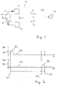
- the generic optoelectronic sensor 10 shown for measuring a distance d from objects 50 has as essential components a transmitter unit 20 for emitting light pulses 22 in a detection area 60, a receiver unit 30 for detecting light pulses 32 from a to-be-measured Object 50 are reflected back in the detection area 60, and a control and evaluation unit 40 on.
- the control and evaluation unit 40 is used to control the transmitter unit 20 and to evaluate the reflected light pulses 32 detected by the receiver unit 30 and is also set up to calculate a time difference between a reception time t2 of a light pulse 32 reflected by the object 50 and a transmission time t1 of this Light pulse 22 to determine a distance d of the object 50 to be measured.
- This basic measurement principle is related to figure 2 described in more detail.
- the diagram shown above shows the transmission power PT (vertical axis 24) of a light source of the transmission unit 20, typically a laser diode, plotted against time t.
- This in figure 2 The diagram below shows the received power PR measured by a receiver, typically a photodiode, in the receiving unit 30 (vertical axis 34) as a function of the time t.
- two points in time must be measured, namely the start point and the reception point.
- a measurement begins with the emission of a light pulse 22, which figure 2 is reproduced by a pulse-like course of the transmission power PT.
- the point in time t1 on the rising edge of pulse 22 at which the edge crosses a selected threshold 26 is selected as the starting point for the time measurement.
- This can be implemented electronically, for example, by querying a current with which a laser diode is driven. Because the current through a laser diode usually has a comparatively defined and reproducible course, the starting point for the time measurement is comparatively well defined.
- the situation when measuring the received pulse is more demanding, essentially because the light pulses are reflected in practical measuring operation by optically very different objects and, in addition, usually a large number of boundary surfaces, such as a windscreen of the sensor.
- the light pulses are therefore subject to a large number of influences that are not precisely defined in the course of their path from the transmitter via the object to the receiver and are changed by these in terms of pulse height and pulse width.
- the in figure 2 In the situation shown in the diagram below, not only is a reception time measured, but the time t2 at which a rising edge of the reception pulse 32 crosses a selected threshold 36 is first determined, and the time t3 is also measured at which the falling edge of the reception pulse 32 passes the Threshold 36 penetrates. It is immediately apparent that with higher and wider pulses, the point in time t2 in the diagram of figure 2 to the left and the point in time t3 migrates accordingly to the right. By providing these two points in time through the measurement, information about the pulse width is obtained, which can be used to correct the time measurement.
- the time measurement as such ie the measurement of the time between the points in time t2 and t1 or the points in time t3 and t1, is carried out using basically known means.
- a first essential approach of the present invention can be seen in the fact that only the comparatively much better defined rising edge of the received pulse is used to determine the time of receipt of a light pulse.
- the essential idea of the present invention is to use light pulses with at least two different pulse heights or pulse energies instead of light pulses with only one pulse height or one pulse energy.
- FIG figure 3 shows a first (stronger) received pulse 321 and a second (weaker) received pulse 322.
- the first received pulse 321 and the second received pulse 322 are simultaneous in the sense that their maxima in this schematic representation of FIG figure 3 coincide. In practice, this will probably also be the case for the most part. But it doesn't matter because the position of the maxima is not measured.
- the rising edge of the stronger first received pulse 321 breaks through the threshold 36 at an earlier point in time t21 than the weaker second received pulse 322, which only breaks through the threshold 36 afterwards at a point in time denoted by t22.
- the present invention has recognized that information about the steepness of the rising edge, for example of the stronger first received pulse 321, is contained in the different points in time t21 and t22. This becomes clear when one realizes that when the same second received pulse 322 is used in each case, the difference between the times t22 and t21 becomes greater the steeper the edge of the first received pulse 321 is.
- a first measurement of the pulse propagation time is carried out with a light pulse 321 with high pulse energy and a second measurement of the pulse propagation time with a light pulse 322 with comparatively weak pulse energy.
- the transit time difference between the two measurements is then used as a measure of the pulse energy.
- This method is similar to a measurement in which the rise time of the received pulses is measured using two different comparator thresholds.
- the use of light pulses 321, 322 of different heights and a single threshold 36 is equivalent to use only one type of light pulses 321, but two different thresholds 361, 362.
- This situation is in figure 4 shown.
- the pulse 321 breaks through the lower threshold 361 (which in the example shown should be the same as the threshold 36 figure 3 ) at time t21 and the higher threshold 362 at time t22.
- the higher threshold 362 is selected in such a way that the point in time t22 in FIG. 4 is identical to the point in time t22 in FIG figure 3 .
- the rise time cannot be determined with the required resolution and accuracy using two comparator thresholds.
- the reasons for this are that the bandwidth of the receiver used limits the shortest possible rise time, so that high pulse energies can no longer be distinguished.
- the limited temporal resolution of the available time-to-digital converter (TDC) prevents a measurement with the desired accuracy. After all, the available receivers do not have the necessary dynamics.
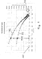
- figure 6 shows two experimentally recorded calibration curves 71, 72.
- the equivalent distance values measured for light pulses with high pulse energy (calibration curve 71) or light pulses with low pulse energy (calibration curve 72) are plotted against the difference ⁇ of these distance values.
- the vertical axis is therefore equivalent to a time axis.
- the data in figure 6 were obtained with a measurement setup in which a reflective target as a test object was positioned at a constant distance relative to the optoelectronic sensor and the reflectivity of the target was varied in a defined manner.
- the reflectivity of the test object increases continuously from left to right.
- the received light pulses both the comparatively strong light pulses, calibration curve 71, and the comparatively weak light pulses, calibration curve 72
- the rising edges of the received light pulses become steeper in each case and break through the selected threshold correspondingly earlier.
- the actual measuring points of the calibration curve 71 are for the comparatively strong light pulses figure 6 with triangles and those of the calibration curve 2 for the comparatively weak light pulses are shown with squares. The curves between these measuring points were interpolated.
- a key aspect of the diagram in figure 6 is that a measured difference ⁇ can be unequivocally associated with a time-of-flight correction or, what is equivalent, a distance correction k( ⁇ ).
- This distance correction k( ⁇ ) can, as in figure 6 shown as an example, are related to the calibration curve 71 for the comparatively strong light pulses. However, it is equivalent if the difference between the straight line k0 and the calibration curve 72 is used for the distance correction. A distance correction obtained in this way would then have to be applied to the measured values obtained for the weak light pulses. Because k0, as discussed, is fixed only up to an additive constant, the distance correction k( ⁇ ) is also fixed only up to an additive constant.
- the method according to the invention has advantages in the regime for very strong light pulses in which the receiver is overdriven.
- the reception times i.e. the times at which the threshold 36 is breached
- the calibration curves 71 and 72 in the limiting case of infinitely strong pulses and thus infinitely steep rising edges converge on one and the same reception time.
- This common point to which the calibration curves 71 and 72 must converge based on this consideration, is in figure 6 highlighted by the circle 73.
- FIG. 7 shows figure 7 a calibration curve 76 from the prior art.
- a measured distance vertical axis
- the pulse width was determined by measuring the times at which the rising edge of a received light pulse and the falling edge of this light pulse crossed a threshold. Due to the overload of the receivers with very intense pulses, there are no diagrams figure 7 Measured values are only available up to a pulse width of about 46000*0.1 mm. Because, in contrast to the situation of the calibration curves 71, 72 for the method according to the invention in figure 6 , no meaningful assumption can be made for the course of the calibration curve 76 for values of the pulse width greater than 50000*0.1mm, it must be extrapolated from the course in the immediate vicinity of 46000*0.1mm.
- the invention provides here, as in connection with figure 6 explained, significant improvements, because the higher the pulse energy of the received light pulses in the method according to the invention (delta amplitude compensation), the lower the measured delta amplitude, which can also be referred to as the delta distance difference. As a result, the maximum uncertainty for the extrapolated amplitudes can be half the delta distance difference. In figure 6 this value is 10 mm. Through a simple linear extrapolation, this error is much lower in practice and can in particular be less than 1 mm.
- FIG 5 shows a schematic representation of an optoelectronic sensor 100 according to the invention.
- the optoelectronic sensor 100 according to the invention is structurally similar to a sensor from the prior art. There are differences in the area of the control and evaluation unit 40. According to the invention, this is set up to control the transmission unit 20 to emit light pulses 221, 222 with at least two different pulse energies and depending on a difference between the reception times t221, t222 measured for the different pulse energies of the received Light pulses 321, 322 to correct the reception time with a correction value k( ⁇ ).
- the control and evaluation unit 40 expediently has a memory 42 for storing the calibration information in the form of the calibration curves 71 , 72 .
- the optoelectronic sensor 100 can have an interface 44, for example a bus interface.
- a novel method for determining a distance from objects using optoelectronic sensors according to the transit time method is provided.
- This method is characterized by a particularly wide range of possible uses, particularly high dynamics of the light pulses that can be used, and particularly high accuracy, particularly in the case of very strong light pulses.
- the invention achieves the object by measuring with successive light pulses with different amplitudes.
- the terms amplitude, pulse energy and pulse height are essentially used synonymously here.
- a time measurement is started, which is terminated, for example, when the echo signal exceeds a specified threshold.
- the received signal that is triggered by a light pulse reflected back from an object is referred to here as an echo signal.
- a propagation time measurement is carried out for each individual transmitted light pulse, which is subject to an amplitude error.
- the evaluation unit can be designed in such a way that it can determine the time difference between two consecutive individual measurements with different transmission amplitudes.
- the invention is based on the knowledge that the time difference between successive measurements with different amplitudes contains information about the amplitude of the echo signals.
- a memory device can be provided, which can contain at least one empirically obtained correction table or curve.
- This correction table or curve can contain correction values that were obtained for at least one constant calibration distance with calibration measurements carried out with different calibration amplitudes.
- a corresponding correction value can be taken from the correction table for each measured time difference of successive individual measurements with different pulse energies of the light pulses.
- a measurement whose measurement result is corrected for the amplitude error consists of at least two consecutive individual measurements in which, in particular, a first measurement is carried out with a low transmission amplitude and a second measurement with a higher transmission amplitude.
- the correction is made using the time difference between the two individual measurements using the empirically determined correction table or curve.
Landscapes
- Engineering & Computer Science (AREA)
- Physics & Mathematics (AREA)
- Computer Networks & Wireless Communication (AREA)
- General Physics & Mathematics (AREA)
- Radar, Positioning & Navigation (AREA)
- Remote Sensing (AREA)
- Electromagnetism (AREA)
- Optical Radar Systems And Details Thereof (AREA)
Claims (10)
- Procédé destiné à mesurer un éloignement d'objets, par lequelune unité d'envoi (20) envoie des impulsions lumineuses (22),une unité de réception (30) détecte des impulsions lumineuses (32) renvoyées par un objet (50) à mesurer etun éloignement (d) de l'objet (50) est déterminé à partir d'une différence temporelle entre un point temporel de réception (t2) d'une impulsion lumineuse (32) et un point temporel d'envoi (t1) de cette impulsion lumineuse (22),dans lequel des impulsions lumineuses (221, 222) sont envoyées avec au moins deux énergies d'impulsion différentes etdans lequel, en tant que point temporel de réception (t21, t22) d'une impulsion lumineuse détectée, est évalué le point temporel vers lequel un front montant de l'impulsion lumineuse (321, 322) détectée transperce un seuil (36), dans lequel une valeur de correction (k(Δ)) est attribuée à une différence (Δ) de points temporels de réception (t21, t22) qui sont mesurés pour deux énergies d'impulsion différentes,dans lequel un des points temporels de réception (t21, t22), en particulier le point temporel de réception (t21) qui est obtenu pour l'impulsion lumineuse (221) avec une énergie d'impulsion plus élevée, est corrigé en ce que la valeur de correction (k(Δ)) est soustraite de ce point temporel de réception (t21) etdans lequel, pour des différences (Δ) différentes des points temporels de réception (t21, t22) mesurés pour les deux énergies d'impulsion différentes, les valeurs de correction (k(Δ)) sont obtenues par des mesures d'étalonnage.
- Procédé selon la revendication 1,
caractérisé en ce que
des courbes d'étalonnage (71, 72) sont établies, auxquelles une valeur de correction (k((Δ)) est attribuée à chaque paire de points temporels de réception (t221, t222) qui sont obtenus pour une paire déterminée d'impulsions lumineuses (221, 222) envoyées avec une énergie d'impulsion différente. - Procédé selon la revendication 2,
caractérisé en ce que
des courbes d'étalonnage (71, 72) sont établies pour des distances différentes des énergies d'impulsion des impulsions lumineuses (221, 222) envoyées. - Procédé selon l'une des revendications 1 à 3,caractérisé en ce queavant un mesurage, des énergies d'impulsion différentes des impulsions lumineuses (221, 222) envoyées et des distances différentes des énergies d'impulsion des impulsions lumineuses (221, 222) envoyées sont testées pour un objet (50) à mesurer etle mesurage est réalisé avec une énergie d'impulsion des impulsions lumineuses (221, 222) et une distance des énergies d'impulsion (221, 222), pour lesquelles une incertitude de mesure aussi réduite que possible est atteinte par référence à des courbes d'étalonnage (71, 72).
- Procédé selon l'une des revendications 1 à 4,
caractérisé en ce que
des mesurages sont réalisés avec plusieurs paires différentes d'énergies d'impulsion différentes des impulsions lumineuses envoyées. - Procédé selon l'une des revendications 1 à 5,
caractérisé en ce que
les impulsions lumineuses (321, 322) détectées sont comparées avec plus d'un seuil (36, 362). - Procédé selon l'une des revendications 1 à 6,
caractérisé en ce que
les énergies d'impulsion des impulsions lumineuses envoyées sont modifiées dans un cycle de mesure. - Procédé selon l'une des revendications 1 à 7,
caractérisé en ce que
les distances d'énergie d'impulsion des impulsions lumineuses envoyées sont augmentées dans une rampe dans un cycle de mesure, sont modifiées selon une fonction triangulaire et/ou selon une fonction en dents de scie. - Capteur optoélectronique destiné à mesurer un éloignement d'objetsavec une unité d'envoi (20) pour envoyer des impulsions lumineuses (22) jusque dans une zone de saisie (60),avec une unité de réception (30) pour détecter des impulsions lumineuses (32) qui sont renvoyées par un objet (50) à mesurer dans la zone de saisie (60), etavec une unité de commande et d'exploitation (40) pour commander l'unité d'envoi (20) et exploiter les impulsions lumineuses (32) détectées par l'unité de réception (30),dans lequel l'unité de commande et d'exploitation (40) est conçue pour déterminer un éloignement (d) de l'objet (50) à mesurer à partir d'une différence temporelle entre un point temporel de réception (t2) d'une impulsion lumineuse (32) et un point temporel d'envoi (t1) de cette impulsion lumineuse (22),commander l'unité d'envoi (20) pour envoyer des impulsions lumineuses (221, 222) avec au moins deux énergies d'impulsion différentes eten tant que point temporel de réception (t21, t22) d'une impulsion lumineuse détectée, évaluer le point temporel vers lequel un front montant de l'impulsion lumineuse (321, 322) détectée transperce un seuil (36),dans lequel l'unité de commande et d'exploitation (40) est en outre conçue pour attribuer une valeur de correction (k(Δ)) à une différence (Δ) de points temporels de réception (t21, t22) qui sont mesurés pour deux énergies d'impulsion différentes,corriger l'un des points temporels de réception (t21, t22), en particulier le point temporel de réception (t21) qui est obtenu pour l'impulsion lumineuse (221) avec une énergie d'impulsion plus élevée, en ce que la valeur de correction (k(Δ)) est soustraite de ce point temporel de réception (t21, t22), et pour des différences (Δ) différentes des points temporels de réception (t21, t22) mesurés pour les deux énergies d'impulsion différentes, obtenir les valeurs de correction (k(Δ)) par des mesures d'étalonnage.
- Capteur optoélectronique selon la revendication 9,
caractérisé en ce que
l'unité de commande et d'exploitation (40) est conçue pour réaliser le procédé selon l'une des revendications 1 à 8 auprès du capteur optoélectronique.
Applications Claiming Priority (1)
| Application Number | Priority Date | Filing Date | Title |
|---|---|---|---|
| DE102018111217.3A DE102018111217A1 (de) | 2018-05-09 | 2018-05-09 | Verfahren und optoelektronischer Sensor zum Messen einer Entfernung von Objekten |
Publications (2)
| Publication Number | Publication Date |
|---|---|
| EP3567397A1 EP3567397A1 (fr) | 2019-11-13 |
| EP3567397B1 true EP3567397B1 (fr) | 2022-07-06 |
Family
ID=66429273
Family Applications (1)
| Application Number | Title | Priority Date | Filing Date |
|---|---|---|---|
| EP19172782.5A Active EP3567397B1 (fr) | 2018-05-09 | 2019-05-06 | Procédé et capteur optoélectronique permettant de mesurer l'éloignement d'objets |
Country Status (2)
| Country | Link |
|---|---|
| EP (1) | EP3567397B1 (fr) |
| DE (1) | DE102018111217A1 (fr) |
Families Citing this family (4)
| Publication number | Priority date | Publication date | Assignee | Title |
|---|---|---|---|---|
| CN114325738B (zh) * | 2021-12-23 | 2023-01-10 | 探维科技(北京)有限公司 | 测量距离的方法及激光雷达 |
| US20230221438A1 (en) * | 2022-01-12 | 2023-07-13 | Luminar, Llc | Lidar system with angle of incidence determination |
| CN114442106B (zh) * | 2022-01-28 | 2025-06-27 | 西安知微传感技术有限公司 | 激光雷达系统的校准方法及装置 |
| CN119439178B (zh) * | 2023-08-03 | 2026-01-06 | 深圳市速腾聚创科技有限公司 | 雷达测距方法、装置、电子设备和计算机可读存储介质 |
Family Cites Families (4)
| Publication number | Priority date | Publication date | Assignee | Title |
|---|---|---|---|---|
| JPH08105971A (ja) * | 1994-10-05 | 1996-04-23 | Hitachi Ltd | マルチパルスによる測距方法とその装置 |
| JP3635166B2 (ja) | 1995-12-27 | 2005-04-06 | 株式会社デンソー | 距離測定方法及び距離測定装置 |
| FI20085665A0 (fi) * | 2008-06-27 | 2008-06-27 | Oulun Yliopisto | Menetelmä ja laite etäisyyden mittaamiseen |
| GB2477065B (en) * | 2008-11-05 | 2012-09-26 | Neptec Design Group Ltd | Return pulse shape analysis for falling edge object discrimination of aerosol lidar |
-
2018
- 2018-05-09 DE DE102018111217.3A patent/DE102018111217A1/de not_active Withdrawn
-
2019
- 2019-05-06 EP EP19172782.5A patent/EP3567397B1/fr active Active
Also Published As
| Publication number | Publication date |
|---|---|
| EP3567397A1 (fr) | 2019-11-13 |
| DE102018111217A1 (de) | 2019-11-14 |
Similar Documents
| Publication | Publication Date | Title |
|---|---|---|
| EP2558883B1 (fr) | Appareil de mesure de distance à évaluation de mesure à effet homogénéisant | |
| EP3567397B1 (fr) | Procédé et capteur optoélectronique permettant de mesurer l'éloignement d'objets | |
| EP2486370B1 (fr) | Télémètre optique avec dispositif d'étalonnage | |
| EP2041604B1 (fr) | Procédé de mesure de distance optique et télémètre optique correspondant | |
| EP1972961B1 (fr) | Capteur optoélectronique et procédé de mesure de l'éloignement ou de la modification de l'éloignement | |
| EP1876469B1 (fr) | Procédé et dispositif destinés à la mesure de distance optoélectronique sans contact selon le principe de durée | |
| EP0793115A2 (fr) | Radar à laser à résolution millimétrique | |
| EP2469296A1 (fr) | Capteur optoélectronique et procédé destiné à la détection et la détermination de l'éloignement d'objets | |
| DE102015217912A1 (de) | Verfahren zur Laufzeitkalibrierung eines Lidarsensors | |
| DE102007021614A1 (de) | Radarvorrichtung | |
| EP1789754A1 (fr) | Dispositif et procede de mesure de distance optique | |
| EP3567398B1 (fr) | Procédé et capteur optoélectronique permettant de mesurer l'éloignement d'objets | |
| EP2962127B1 (fr) | Procédé de détermination d'une distance d'un objet par rapport à un véhicule à moteur en utilisant un capteur pmd | |
| WO2008003481A1 (fr) | Procédé et dispositif demesure d'une distance de manière optoélectronique sans contact | |
| EP2565669B1 (fr) | Procédé destiné à supprimer un échosignal | |
| DE102004031024B4 (de) | Optischer Sensor | |
| EP4249950A1 (fr) | Détection et détermination de la distance d'un objet | |
| EP4252026B1 (fr) | Procédé de fonctionnement d'un dispositif de détection pour déterminer des variables de distance avec réglage de température, dispositif de détection correspondant et véhicule comportant au moins un dispositif de détection de ce type | |
| DE102010064682B3 (de) | Optoelektronischer Sensor und Verfahren zur Erfassung und Abstandsbestimmung von Objekten | |
| EP3951425A1 (fr) | Procédé, ainsi que dispositif de mesure permettant de déterminer une distance | |
| EP4102249B1 (fr) | Méthode et capteur optique pour mesurer une distance d'un objet | |
| AT508344B1 (de) | Verfahren zur aufnahme eines objektraumes | |
| DE102023124256A1 (de) | Verfahren zum erhalten von winkelwerten einer drehbewegung und optisches detektionssystem | |
| DE102021117361A1 (de) | Verfahren zum Betreiben einer optischen Detektionsvorrichtung, Detektionsvorrichtung und Fahrzeug mit wenigstens einer Detektionsvorrichtung | |
| DE102010039295A1 (de) | Entfernungsmessgerät mit homogenisierender Messauswertung |
Legal Events
| Date | Code | Title | Description |
|---|---|---|---|
| PUAI | Public reference made under article 153(3) epc to a published international application that has entered the european phase |
Free format text: ORIGINAL CODE: 0009012 |
|
| STAA | Information on the status of an ep patent application or granted ep patent |
Free format text: STATUS: THE APPLICATION HAS BEEN PUBLISHED |
|
| AK | Designated contracting states |
Kind code of ref document: A1 Designated state(s): AL AT BE BG CH CY CZ DE DK EE ES FI FR GB GR HR HU IE IS IT LI LT LU LV MC MK MT NL NO PL PT RO RS SE SI SK SM TR |
|
| AX | Request for extension of the european patent |
Extension state: BA ME |
|
| STAA | Information on the status of an ep patent application or granted ep patent |
Free format text: STATUS: REQUEST FOR EXAMINATION WAS MADE |
|
| 17P | Request for examination filed |
Effective date: 20200513 |
|
| RBV | Designated contracting states (corrected) |
Designated state(s): AL AT BE BG CH CY CZ DE DK EE ES FI FR GB GR HR HU IE IS IT LI LT LU LV MC MK MT NL NO PL PT RO RS SE SI SK SM TR |
|
| GRAP | Despatch of communication of intention to grant a patent |
Free format text: ORIGINAL CODE: EPIDOSNIGR1 |
|
| STAA | Information on the status of an ep patent application or granted ep patent |
Free format text: STATUS: GRANT OF PATENT IS INTENDED |
|
| INTG | Intention to grant announced |
Effective date: 20211117 |
|
| GRAS | Grant fee paid |
Free format text: ORIGINAL CODE: EPIDOSNIGR3 |
|
| RAP3 | Party data changed (applicant data changed or rights of an application transferred) |
Owner name: PEPPERL+FUCHS SE |
|
| GRAA | (expected) grant |
Free format text: ORIGINAL CODE: 0009210 |
|
| STAA | Information on the status of an ep patent application or granted ep patent |
Free format text: STATUS: THE PATENT HAS BEEN GRANTED |
|
| AK | Designated contracting states |
Kind code of ref document: B1 Designated state(s): AL AT BE BG CH CY CZ DE DK EE ES FI FR GB GR HR HU IE IS IT LI LT LU LV MC MK MT NL NO PL PT RO RS SE SI SK SM TR |
|
| REG | Reference to a national code |
Ref country code: AT Ref legal event code: REF Ref document number: 1503237 Country of ref document: AT Kind code of ref document: T Effective date: 20220715 Ref country code: CH Ref legal event code: EP |
|
| REG | Reference to a national code |
Ref country code: DE Ref legal event code: R096 Ref document number: 502019004850 Country of ref document: DE |
|
| REG | Reference to a national code |
Ref country code: IE Ref legal event code: FG4D Free format text: LANGUAGE OF EP DOCUMENT: GERMAN |
|
| REG | Reference to a national code |
Ref country code: LT Ref legal event code: MG9D |
|
| REG | Reference to a national code |
Ref country code: NL Ref legal event code: MP Effective date: 20220706 |
|
| PG25 | Lapsed in a contracting state [announced via postgrant information from national office to epo] |
Ref country code: SE Free format text: LAPSE BECAUSE OF FAILURE TO SUBMIT A TRANSLATION OF THE DESCRIPTION OR TO PAY THE FEE WITHIN THE PRESCRIBED TIME-LIMIT Effective date: 20220706 Ref country code: RS Free format text: LAPSE BECAUSE OF FAILURE TO SUBMIT A TRANSLATION OF THE DESCRIPTION OR TO PAY THE FEE WITHIN THE PRESCRIBED TIME-LIMIT Effective date: 20220706 Ref country code: PT Free format text: LAPSE BECAUSE OF FAILURE TO SUBMIT A TRANSLATION OF THE DESCRIPTION OR TO PAY THE FEE WITHIN THE PRESCRIBED TIME-LIMIT Effective date: 20221107 Ref country code: NO Free format text: LAPSE BECAUSE OF FAILURE TO SUBMIT A TRANSLATION OF THE DESCRIPTION OR TO PAY THE FEE WITHIN THE PRESCRIBED TIME-LIMIT Effective date: 20221006 Ref country code: NL Free format text: LAPSE BECAUSE OF FAILURE TO SUBMIT A TRANSLATION OF THE DESCRIPTION OR TO PAY THE FEE WITHIN THE PRESCRIBED TIME-LIMIT Effective date: 20220706 Ref country code: LV Free format text: LAPSE BECAUSE OF FAILURE TO SUBMIT A TRANSLATION OF THE DESCRIPTION OR TO PAY THE FEE WITHIN THE PRESCRIBED TIME-LIMIT Effective date: 20220706 Ref country code: LT Free format text: LAPSE BECAUSE OF FAILURE TO SUBMIT A TRANSLATION OF THE DESCRIPTION OR TO PAY THE FEE WITHIN THE PRESCRIBED TIME-LIMIT Effective date: 20220706 Ref country code: FI Free format text: LAPSE BECAUSE OF FAILURE TO SUBMIT A TRANSLATION OF THE DESCRIPTION OR TO PAY THE FEE WITHIN THE PRESCRIBED TIME-LIMIT Effective date: 20220706 Ref country code: ES Free format text: LAPSE BECAUSE OF FAILURE TO SUBMIT A TRANSLATION OF THE DESCRIPTION OR TO PAY THE FEE WITHIN THE PRESCRIBED TIME-LIMIT Effective date: 20220706 |
|
| PG25 | Lapsed in a contracting state [announced via postgrant information from national office to epo] |
Ref country code: PL Free format text: LAPSE BECAUSE OF FAILURE TO SUBMIT A TRANSLATION OF THE DESCRIPTION OR TO PAY THE FEE WITHIN THE PRESCRIBED TIME-LIMIT Effective date: 20220706 Ref country code: IS Free format text: LAPSE BECAUSE OF FAILURE TO SUBMIT A TRANSLATION OF THE DESCRIPTION OR TO PAY THE FEE WITHIN THE PRESCRIBED TIME-LIMIT Effective date: 20221106 Ref country code: HR Free format text: LAPSE BECAUSE OF FAILURE TO SUBMIT A TRANSLATION OF THE DESCRIPTION OR TO PAY THE FEE WITHIN THE PRESCRIBED TIME-LIMIT Effective date: 20220706 Ref country code: GR Free format text: LAPSE BECAUSE OF FAILURE TO SUBMIT A TRANSLATION OF THE DESCRIPTION OR TO PAY THE FEE WITHIN THE PRESCRIBED TIME-LIMIT Effective date: 20221007 |
|
| REG | Reference to a national code |
Ref country code: DE Ref legal event code: R097 Ref document number: 502019004850 Country of ref document: DE |
|
| PG25 | Lapsed in a contracting state [announced via postgrant information from national office to epo] |
Ref country code: SM Free format text: LAPSE BECAUSE OF FAILURE TO SUBMIT A TRANSLATION OF THE DESCRIPTION OR TO PAY THE FEE WITHIN THE PRESCRIBED TIME-LIMIT Effective date: 20220706 Ref country code: RO Free format text: LAPSE BECAUSE OF FAILURE TO SUBMIT A TRANSLATION OF THE DESCRIPTION OR TO PAY THE FEE WITHIN THE PRESCRIBED TIME-LIMIT Effective date: 20220706 Ref country code: DK Free format text: LAPSE BECAUSE OF FAILURE TO SUBMIT A TRANSLATION OF THE DESCRIPTION OR TO PAY THE FEE WITHIN THE PRESCRIBED TIME-LIMIT Effective date: 20220706 Ref country code: CZ Free format text: LAPSE BECAUSE OF FAILURE TO SUBMIT A TRANSLATION OF THE DESCRIPTION OR TO PAY THE FEE WITHIN THE PRESCRIBED TIME-LIMIT Effective date: 20220706 |
|
| PLBE | No opposition filed within time limit |
Free format text: ORIGINAL CODE: 0009261 |
|
| STAA | Information on the status of an ep patent application or granted ep patent |
Free format text: STATUS: NO OPPOSITION FILED WITHIN TIME LIMIT |
|
| PG25 | Lapsed in a contracting state [announced via postgrant information from national office to epo] |
Ref country code: SK Free format text: LAPSE BECAUSE OF FAILURE TO SUBMIT A TRANSLATION OF THE DESCRIPTION OR TO PAY THE FEE WITHIN THE PRESCRIBED TIME-LIMIT Effective date: 20220706 Ref country code: EE Free format text: LAPSE BECAUSE OF FAILURE TO SUBMIT A TRANSLATION OF THE DESCRIPTION OR TO PAY THE FEE WITHIN THE PRESCRIBED TIME-LIMIT Effective date: 20220706 |
|
| 26N | No opposition filed |
Effective date: 20230411 |
|
| PG25 | Lapsed in a contracting state [announced via postgrant information from national office to epo] |
Ref country code: AL Free format text: LAPSE BECAUSE OF FAILURE TO SUBMIT A TRANSLATION OF THE DESCRIPTION OR TO PAY THE FEE WITHIN THE PRESCRIBED TIME-LIMIT Effective date: 20220706 |
|
| PG25 | Lapsed in a contracting state [announced via postgrant information from national office to epo] |
Ref country code: SI Free format text: LAPSE BECAUSE OF FAILURE TO SUBMIT A TRANSLATION OF THE DESCRIPTION OR TO PAY THE FEE WITHIN THE PRESCRIBED TIME-LIMIT Effective date: 20220706 |
|
| PG25 | Lapsed in a contracting state [announced via postgrant information from national office to epo] |
Ref country code: MC Free format text: LAPSE BECAUSE OF FAILURE TO SUBMIT A TRANSLATION OF THE DESCRIPTION OR TO PAY THE FEE WITHIN THE PRESCRIBED TIME-LIMIT Effective date: 20220706 |
|
| GBPC | Gb: european patent ceased through non-payment of renewal fee |
Effective date: 20230506 |
|
| REG | Reference to a national code |
Ref country code: BE Ref legal event code: MM Effective date: 20230531 |
|
| PG25 | Lapsed in a contracting state [announced via postgrant information from national office to epo] |
Ref country code: MC Free format text: LAPSE BECAUSE OF FAILURE TO SUBMIT A TRANSLATION OF THE DESCRIPTION OR TO PAY THE FEE WITHIN THE PRESCRIBED TIME-LIMIT Effective date: 20220706 Ref country code: LU Free format text: LAPSE BECAUSE OF NON-PAYMENT OF DUE FEES Effective date: 20230506 Ref country code: IT Free format text: LAPSE BECAUSE OF FAILURE TO SUBMIT A TRANSLATION OF THE DESCRIPTION OR TO PAY THE FEE WITHIN THE PRESCRIBED TIME-LIMIT Effective date: 20220706 |
|
| REG | Reference to a national code |
Ref country code: IE Ref legal event code: MM4A |
|
| PG25 | Lapsed in a contracting state [announced via postgrant information from national office to epo] |
Ref country code: IE Free format text: LAPSE BECAUSE OF NON-PAYMENT OF DUE FEES Effective date: 20230506 |
|
| PG25 | Lapsed in a contracting state [announced via postgrant information from national office to epo] |
Ref country code: IE Free format text: LAPSE BECAUSE OF NON-PAYMENT OF DUE FEES Effective date: 20230506 Ref country code: GB Free format text: LAPSE BECAUSE OF NON-PAYMENT OF DUE FEES Effective date: 20230506 |
|
| PG25 | Lapsed in a contracting state [announced via postgrant information from national office to epo] |
Ref country code: BE Free format text: LAPSE BECAUSE OF NON-PAYMENT OF DUE FEES Effective date: 20230531 |
|
| PG25 | Lapsed in a contracting state [announced via postgrant information from national office to epo] |
Ref country code: BG Free format text: LAPSE BECAUSE OF FAILURE TO SUBMIT A TRANSLATION OF THE DESCRIPTION OR TO PAY THE FEE WITHIN THE PRESCRIBED TIME-LIMIT Effective date: 20220706 |
|
| PG25 | Lapsed in a contracting state [announced via postgrant information from national office to epo] |
Ref country code: BG Free format text: LAPSE BECAUSE OF FAILURE TO SUBMIT A TRANSLATION OF THE DESCRIPTION OR TO PAY THE FEE WITHIN THE PRESCRIBED TIME-LIMIT Effective date: 20220706 |
|
| PGFP | Annual fee paid to national office [announced via postgrant information from national office to epo] |
Ref country code: DE Payment date: 20250519 Year of fee payment: 7 |
|
| PGFP | Annual fee paid to national office [announced via postgrant information from national office to epo] |
Ref country code: FR Payment date: 20250523 Year of fee payment: 7 |
|
| PGFP | Annual fee paid to national office [announced via postgrant information from national office to epo] |
Ref country code: CH Payment date: 20250601 Year of fee payment: 7 |
|
| PGFP | Annual fee paid to national office [announced via postgrant information from national office to epo] |
Ref country code: AT Payment date: 20250519 Year of fee payment: 7 |
|
| PG25 | Lapsed in a contracting state [announced via postgrant information from national office to epo] |
Ref country code: CY Free format text: LAPSE BECAUSE OF FAILURE TO SUBMIT A TRANSLATION OF THE DESCRIPTION OR TO PAY THE FEE WITHIN THE PRESCRIBED TIME-LIMIT; INVALID AB INITIO Effective date: 20190506 |
|
| PG25 | Lapsed in a contracting state [announced via postgrant information from national office to epo] |
Ref country code: HU Free format text: LAPSE BECAUSE OF FAILURE TO SUBMIT A TRANSLATION OF THE DESCRIPTION OR TO PAY THE FEE WITHIN THE PRESCRIBED TIME-LIMIT; INVALID AB INITIO Effective date: 20190506 |
|
| PG25 | Lapsed in a contracting state [announced via postgrant information from national office to epo] |
Ref country code: TR Free format text: LAPSE BECAUSE OF FAILURE TO SUBMIT A TRANSLATION OF THE DESCRIPTION OR TO PAY THE FEE WITHIN THE PRESCRIBED TIME-LIMIT Effective date: 20220706 |