EP3567397B1 - Method and optoelectronic sensor for measuring the distance of objects - Google Patents
Method and optoelectronic sensor for measuring the distance of objects Download PDFInfo
- Publication number
- EP3567397B1 EP3567397B1 EP19172782.5A EP19172782A EP3567397B1 EP 3567397 B1 EP3567397 B1 EP 3567397B1 EP 19172782 A EP19172782 A EP 19172782A EP 3567397 B1 EP3567397 B1 EP 3567397B1
- Authority
- EP
- European Patent Office
- Prior art keywords
- pulse
- light pulses
- time
- measured
- reception
- Prior art date
- Legal status (The legal status is an assumption and is not a legal conclusion. Google has not performed a legal analysis and makes no representation as to the accuracy of the status listed.)
- Active
Links
Images


Classifications
-
- G—PHYSICS
- G01—MEASURING; TESTING
- G01S—RADIO DIRECTION-FINDING; RADIO NAVIGATION; DETERMINING DISTANCE OR VELOCITY BY USE OF RADIO WAVES; LOCATING OR PRESENCE-DETECTING BY USE OF THE REFLECTION OR RERADIATION OF RADIO WAVES; ANALOGOUS ARRANGEMENTS USING OTHER WAVES
- G01S7/00—Details of systems according to groups G01S13/00, G01S15/00, G01S17/00
- G01S7/48—Details of systems according to groups G01S13/00, G01S15/00, G01S17/00 of systems according to group G01S17/00
- G01S7/483—Details of pulse systems
- G01S7/486—Receivers
- G01S7/4865—Time delay measurement, e.g. time-of-flight measurement, time of arrival measurement or determining the exact position of a peak
-
- G—PHYSICS
- G01—MEASURING; TESTING
- G01S—RADIO DIRECTION-FINDING; RADIO NAVIGATION; DETERMINING DISTANCE OR VELOCITY BY USE OF RADIO WAVES; LOCATING OR PRESENCE-DETECTING BY USE OF THE REFLECTION OR RERADIATION OF RADIO WAVES; ANALOGOUS ARRANGEMENTS USING OTHER WAVES
- G01S17/00—Systems using the reflection or reradiation of electromagnetic waves other than radio waves, e.g. lidar systems
- G01S17/02—Systems using the reflection of electromagnetic waves other than radio waves
- G01S17/06—Systems determining position data of a target
- G01S17/08—Systems determining position data of a target for measuring distance only
- G01S17/10—Systems determining position data of a target for measuring distance only using transmission of interrupted, pulse-modulated waves
-
- G—PHYSICS
- G01—MEASURING; TESTING
- G01S—RADIO DIRECTION-FINDING; RADIO NAVIGATION; DETERMINING DISTANCE OR VELOCITY BY USE OF RADIO WAVES; LOCATING OR PRESENCE-DETECTING BY USE OF THE REFLECTION OR RERADIATION OF RADIO WAVES; ANALOGOUS ARRANGEMENTS USING OTHER WAVES
- G01S7/00—Details of systems according to groups G01S13/00, G01S15/00, G01S17/00
- G01S7/48—Details of systems according to groups G01S13/00, G01S15/00, G01S17/00 of systems according to group G01S17/00
- G01S7/483—Details of pulse systems
- G01S7/484—Transmitters
-
- G—PHYSICS
- G01—MEASURING; TESTING
- G01S—RADIO DIRECTION-FINDING; RADIO NAVIGATION; DETERMINING DISTANCE OR VELOCITY BY USE OF RADIO WAVES; LOCATING OR PRESENCE-DETECTING BY USE OF THE REFLECTION OR RERADIATION OF RADIO WAVES; ANALOGOUS ARRANGEMENTS USING OTHER WAVES
- G01S7/00—Details of systems according to groups G01S13/00, G01S15/00, G01S17/00
- G01S7/48—Details of systems according to groups G01S13/00, G01S15/00, G01S17/00 of systems according to group G01S17/00
- G01S7/483—Details of pulse systems
- G01S7/486—Receivers
- G01S7/4868—Controlling received signal intensity or exposure of sensor
-
- G—PHYSICS
- G01—MEASURING; TESTING
- G01S—RADIO DIRECTION-FINDING; RADIO NAVIGATION; DETERMINING DISTANCE OR VELOCITY BY USE OF RADIO WAVES; LOCATING OR PRESENCE-DETECTING BY USE OF THE REFLECTION OR RERADIATION OF RADIO WAVES; ANALOGOUS ARRANGEMENTS USING OTHER WAVES
- G01S7/00—Details of systems according to groups G01S13/00, G01S15/00, G01S17/00
- G01S7/48—Details of systems according to groups G01S13/00, G01S15/00, G01S17/00 of systems according to group G01S17/00
- G01S7/497—Means for monitoring or calibrating
Definitions
- the present invention relates to a method for measuring a distance from objects.
- the invention relates to an optoelectronic sensor for measuring a distance of objects.
- a transmitter unit emits light pulses
- a receiver unit detects light pulses reflected back from an object to be measured
- a distance of the object is determined from a time difference between the time at which a light pulse is received and the time at which this light pulse is emitted.
- a generic optoelectronic sensor for measuring a distance from objects has the following components: a transmitter unit for emitting light pulses into a detection area, a receiver unit for detecting light pulses that are reflected by an object to be measured in the detection area, and a control and evaluation unit for Controlling the transmitter unit and evaluating the light pulses detected by the receiver unit.
- the control and evaluation unit is set up to determine a distance of the object to be measured from a time difference between the time at which a light pulse is received and the time at which this light pulse is emitted.
- a generic method and a generic optoelectronic sensor are for example in EP 0 782 007 A2 described.
- Photoelectric sensors for non-contact distance measurement are divided into different categories depending on the process used.
- a first way of measuring distances very precisely is to measure the phase position of the transmitted and received waves.
- a laser diode emits sine waves.
- the distance can be determined.
- short pulses are emitted from a light source in the case of pulse propagation time methods.
- the distance of the reflecting object can be determined by measuring the transit time between the emission of the pulse and the detection of the reflected light.
- the present invention relates to this method and the associated device.
- An echo pulse is a light pulse that is reflected by an object to be measured in the detection area and detected in the receiving unit.
- Conventional pulse methods send a single pulse and determine the position of the echo pulse that is then received.
- the echo pulse is distinguished from interference signals by a comparator threshold. This only works reliably if the interference signals are clearly smaller than the smallest echo pulses to be resolved.
- the slew rates of the echo signal are also different for different amplitudes of the echo signal.
- a close object of high reflectivity, such as a triple reflector, which is also referred to as a cooperative target, on the one hand and a distant object of low reflectivity on the other hand differ in practice with regard to the intensity remitted by the objects and thus the echo signal amplitude by orders of magnitude of up to a factor of 1 million or more.
- a receiving unit that is supposed to cover this dynamic range will inevitably overdrive in the case of high echo amplitudes.
- the determination of the reception time by means of a comparator threshold is therefore dependent on the rate of rise and the signal amplitude of the echo signal, e.g. Am EP 0 782 007 A2 , figure 1 shown.
- FIG 2 from EP 0 782 007 A2 shows that the rate of rise of the received signal can be determined by measuring using two thresholds on the rising edge, and a more precise propagation time measurement is possible.
- EP 0 782 007 A2 describes a method and a procedure for running time measurement by measuring the time interval between exceeding the threshold (rising edge of the received signal) and falling below the threshold on the falling edge. A correction is determined based on the measured time interval.
- the disadvantage here is that several time measurements must be carried out in quick succession with very high accuracy in the picosecond range and different thresholds. Determining the time interval between exceeding and falling below the threshold on the rising or falling edge of the echo signal does not work if the receiver is overloaded.
- the reflectivity of an object to be detected can change the measured propagation time in such a way that a strongly reflecting object leads to an earlier triggering of the receiver and a weakly reflecting object to a later triggering of the receiver.
- This so-called amplitude error can be calculated by detecting the pulse energy or the pulse width and subtracted from the measured propagation time. This method is known under the term amplitude compensation.
- the amplitude of the received pulses is kept constant with an optical brightness regulator, for example an aperture wheel.
- an optical brightness regulator for example an aperture wheel.
- WO 2009/156580 A1 describes a transit time method in which received pulses are sampled using a plurality of thresholds.
- WO 2010/051615 A1 discloses a transit time method in which the falling edge of the received pulses are sampled.
- JP H08 105971 A describes a transit time method in which transmission pulses with different energies are transmitted and a correction value for the time of reception is obtained from the amplitude ratio of the different pulses.
- One object of the present invention can be seen as a method for determining the distance from objects and an optoelectronic sensor to indicate this, in which a particularly high level of accuracy can be achieved.
- this object is achieved by the method with features 1.
- the method is solved by the optoelectronic sensor having the features of claim 9 .
- the method of the type specified above is further developed according to the invention in that light pulses are emitted with at least two different pulse energies and that the reception times are corrected with a correction value depending on differences in the reception times measured for the different pulse energies.
- control and evaluation unit is set up to control the transmission unit to emit light pulses with at least two different pulse energies and, depending on a difference in the reception times of the received light pulses measured for the different pulse energies To correct the reception time with a correction value.
- control and evaluation unit is preferably set up to carry out the method with the optoelectronic sensor.
- An essential basic idea of the invention can be seen as using light pulses with at least two different pulse energies instead of light pulses with only one pulse height or pulse energy. This basic idea is based on the finding that when measuring with light pulses with at least two different pulse energies, additional information about the steepness of the edge can be obtained, even if only the rising edge of the pulses is used for the measurement.
- inaccuracies resulting from the amplitude of a received light pulse can be corrected with particularly good accuracy, and overall the accuracy of the distance measurement can be significantly increased by measuring the transit time.
- Measuring the time of receipt of received light pulses with at least two different pulse energies using a comparator threshold is in principle equivalent to measuring the rising edge of the received light pulses with a single pulse energy and using two different comparator thresholds.
- the use according to the invention of light pulses with at least two different pulse energies has the advantage that the ratios of the pulse energies can be selected to be significantly larger than the ratios of two different comparator thresholds. As a result, this means that the rise time of the received light pulse can be resolved much more precisely and recorded in a higher dynamic range.
- the measurement of the reception times of light pulses with different pulse heights provides information about the rise time and thus also about the pulse heights or pulse energies of the light pulses used.
- the variables rise time, pulse height and pulse energy are functionally monotonically related to one another. Therefore, when speaking of a measurement of the rise time, the principle also includes and means a measurement of the pulse height and the pulse energy.
- the method according to the invention supplies very high-quality measurement data.
- the measured pulse energies and the correction values determined on this basis have a very low temperature dependency because the temperature-related influencing variables can be eliminated, in particular by subtracting raw measured values.
- the method according to the invention is therefore also well suited for simple receivers with a low bandwidth.
- the difference between the reception times measured for light pulses with different pulse energies is also referred to as the delta amplitude for the purposes of the present description.
- Narrow bandwidth receivers benefit from higher delta amplitude resolution.
- the measured delta amplitude is significantly less influenced by attenuation in the signal path, for example by a dirty windscreen of the optoelectronic sensor.
- the demands on the receiver are also significantly lower than with methods that use conventional amplitude compensation because the behavior of the receiver is practically irrelevant with increasing overload.
- the reason for this is that a possibly poorly defined and, in particular, non-constant relationship between pulse energy and pulse width no longer affects the measurement accuracy. Accordingly, it is sufficient for the design of the receiver to focus exclusively on the optimization of the rising edge.
- the pulse energy is in principle recorded with the same measuring accuracy as the signal propagation time itself.
- the measured value is not worsened by an insufficient correction value. Because, in addition, reflections can occur at the earliest after the first arrival of the light at the electro-optical sensor, multiple reflections can no longer play a disadvantageous role.
- the method according to the invention is therefore absolutely immune to multiple reflections.
- the method according to the invention also has the advantage that the compensation method proposed here is not based on the signal level to compensate for the distance error, as is the case with conventional amplitude compensation based on a pulse width measurement, but on a transit time error itself. This means that the differences in the reception times for received light pulses with different pulse energies at weak signal levels are particularly large. The distance error caused by this, on the other hand, is comparatively small.
- a correction value can be determined using a correction function or table depending on the amplitude of the echo signal, ie the amplitude or energy of a received light pulse.
- the reception times for the stronger light pulses or the reception times for the weaker light pulses can serve as the starting point for the correction.
- a received light pulse is assigned a reception time in a defined manner. According to the invention, that time is used as the time of receipt evaluated at which a rising edge of a detected light pulse crosses a threshold.
- the measured reception times can be corrected by multiplying them by a correction factor.
- the reception time is corrected with a correction value to be subtracted.
- a correction value is referred to as an additive correction value.
- This also includes negative values, i.e. values to be subtracted.
- both the time of reception of the weaker light pulses or the time of reception of the stronger light pulses can be used as the starting point for the correction.
- a correction value to be subtracted from one of the reception times is assigned to differences in the reception times measured for two different pulse energies.
- the correction values are only fixed up to an additive constant that can basically be freely selected.
- the correction values are obtained by calibration measurements for different differences in the reception times measured for the different pulse energies.
- Such measurements can, for example, be carried out at the factory prior to delivery of an optoelectronic sensor according to the invention to a customer, but optionally also during ongoing measurement operation.
- calibration curves can be determined which assign a correction value to each pair of reception times obtained for a specific pair of transmitted light pulses with different pulse energies.
- the information base for determining suitable correction values can be increased in variants of the method according to the invention, in which calibration curves are determined for different distances between the pulse energies of the transmitted light pulses.
- a further advantageous variant of the method according to the invention is characterized in that before a measurement, different pulse energies of the transmitted light pulses and different spacings of the pulse energies of the transmitted light pulses are tested for an object to be measured and that the measurement is carried out with a pulse energy of the transmitted light pulses and a spacing of the pulse energies is carried out in which the lowest possible measurement uncertainty is achieved according to the calibration curves.
- the inventive use of light pulses with different pulse energies has advantages compared to measurements with different thresholds
- the measurement with different thresholds has the advantage that the measured values are generated simultaneously and the measurement as such is therefore faster.
- This advantage can be utilized in variants of the method according to the invention in which the detected light pulses are compared to more than one threshold.
- a sequence of light pulses is particularly preferably emitted, which consists alternately of light pulses with low and high transmission amplitudes.
- a correction based on the time difference can be carried out for two consecutive individual measurements. With n individual measurements, one obtains n-1 corrected measurements.
- the pulse energies of the transmitted light pulses to be varied in a measurement cycle and, in particular, to be ramped up are varied according to a triangular function and/or according to a sawtooth function.
- the rising edge of the received light pulses can be measured even more precisely and the measured distance values can be corrected even more precisely.
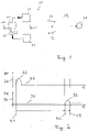
- the generic optoelectronic sensor 10 shown for measuring a distance d from objects 50 has as essential components a transmitter unit 20 for emitting light pulses 22 in a detection area 60, a receiver unit 30 for detecting light pulses 32 from a to-be-measured Object 50 are reflected back in the detection area 60, and a control and evaluation unit 40 on.
- the control and evaluation unit 40 is used to control the transmitter unit 20 and to evaluate the reflected light pulses 32 detected by the receiver unit 30 and is also set up to calculate a time difference between a reception time t2 of a light pulse 32 reflected by the object 50 and a transmission time t1 of this Light pulse 22 to determine a distance d of the object 50 to be measured.
- This basic measurement principle is related to figure 2 described in more detail.
- the diagram shown above shows the transmission power PT (vertical axis 24) of a light source of the transmission unit 20, typically a laser diode, plotted against time t.
- This in figure 2 The diagram below shows the received power PR measured by a receiver, typically a photodiode, in the receiving unit 30 (vertical axis 34) as a function of the time t.
- two points in time must be measured, namely the start point and the reception point.
- a measurement begins with the emission of a light pulse 22, which figure 2 is reproduced by a pulse-like course of the transmission power PT.
- the point in time t1 on the rising edge of pulse 22 at which the edge crosses a selected threshold 26 is selected as the starting point for the time measurement.
- This can be implemented electronically, for example, by querying a current with which a laser diode is driven. Because the current through a laser diode usually has a comparatively defined and reproducible course, the starting point for the time measurement is comparatively well defined.
- the situation when measuring the received pulse is more demanding, essentially because the light pulses are reflected in practical measuring operation by optically very different objects and, in addition, usually a large number of boundary surfaces, such as a windscreen of the sensor.
- the light pulses are therefore subject to a large number of influences that are not precisely defined in the course of their path from the transmitter via the object to the receiver and are changed by these in terms of pulse height and pulse width.
- the in figure 2 In the situation shown in the diagram below, not only is a reception time measured, but the time t2 at which a rising edge of the reception pulse 32 crosses a selected threshold 36 is first determined, and the time t3 is also measured at which the falling edge of the reception pulse 32 passes the Threshold 36 penetrates. It is immediately apparent that with higher and wider pulses, the point in time t2 in the diagram of figure 2 to the left and the point in time t3 migrates accordingly to the right. By providing these two points in time through the measurement, information about the pulse width is obtained, which can be used to correct the time measurement.
- the time measurement as such ie the measurement of the time between the points in time t2 and t1 or the points in time t3 and t1, is carried out using basically known means.
- a first essential approach of the present invention can be seen in the fact that only the comparatively much better defined rising edge of the received pulse is used to determine the time of receipt of a light pulse.
- the essential idea of the present invention is to use light pulses with at least two different pulse heights or pulse energies instead of light pulses with only one pulse height or one pulse energy.
- FIG figure 3 shows a first (stronger) received pulse 321 and a second (weaker) received pulse 322.
- the first received pulse 321 and the second received pulse 322 are simultaneous in the sense that their maxima in this schematic representation of FIG figure 3 coincide. In practice, this will probably also be the case for the most part. But it doesn't matter because the position of the maxima is not measured.
- the rising edge of the stronger first received pulse 321 breaks through the threshold 36 at an earlier point in time t21 than the weaker second received pulse 322, which only breaks through the threshold 36 afterwards at a point in time denoted by t22.
- the present invention has recognized that information about the steepness of the rising edge, for example of the stronger first received pulse 321, is contained in the different points in time t21 and t22. This becomes clear when one realizes that when the same second received pulse 322 is used in each case, the difference between the times t22 and t21 becomes greater the steeper the edge of the first received pulse 321 is.
- a first measurement of the pulse propagation time is carried out with a light pulse 321 with high pulse energy and a second measurement of the pulse propagation time with a light pulse 322 with comparatively weak pulse energy.
- the transit time difference between the two measurements is then used as a measure of the pulse energy.
- This method is similar to a measurement in which the rise time of the received pulses is measured using two different comparator thresholds.
- the use of light pulses 321, 322 of different heights and a single threshold 36 is equivalent to use only one type of light pulses 321, but two different thresholds 361, 362.
- This situation is in figure 4 shown.
- the pulse 321 breaks through the lower threshold 361 (which in the example shown should be the same as the threshold 36 figure 3 ) at time t21 and the higher threshold 362 at time t22.
- the higher threshold 362 is selected in such a way that the point in time t22 in FIG. 4 is identical to the point in time t22 in FIG figure 3 .
- the rise time cannot be determined with the required resolution and accuracy using two comparator thresholds.
- the reasons for this are that the bandwidth of the receiver used limits the shortest possible rise time, so that high pulse energies can no longer be distinguished.
- the limited temporal resolution of the available time-to-digital converter (TDC) prevents a measurement with the desired accuracy. After all, the available receivers do not have the necessary dynamics.
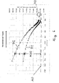
- figure 6 shows two experimentally recorded calibration curves 71, 72.
- the equivalent distance values measured for light pulses with high pulse energy (calibration curve 71) or light pulses with low pulse energy (calibration curve 72) are plotted against the difference ⁇ of these distance values.
- the vertical axis is therefore equivalent to a time axis.
- the data in figure 6 were obtained with a measurement setup in which a reflective target as a test object was positioned at a constant distance relative to the optoelectronic sensor and the reflectivity of the target was varied in a defined manner.
- the reflectivity of the test object increases continuously from left to right.
- the received light pulses both the comparatively strong light pulses, calibration curve 71, and the comparatively weak light pulses, calibration curve 72
- the rising edges of the received light pulses become steeper in each case and break through the selected threshold correspondingly earlier.
- the actual measuring points of the calibration curve 71 are for the comparatively strong light pulses figure 6 with triangles and those of the calibration curve 2 for the comparatively weak light pulses are shown with squares. The curves between these measuring points were interpolated.
- a key aspect of the diagram in figure 6 is that a measured difference ⁇ can be unequivocally associated with a time-of-flight correction or, what is equivalent, a distance correction k( ⁇ ).
- This distance correction k( ⁇ ) can, as in figure 6 shown as an example, are related to the calibration curve 71 for the comparatively strong light pulses. However, it is equivalent if the difference between the straight line k0 and the calibration curve 72 is used for the distance correction. A distance correction obtained in this way would then have to be applied to the measured values obtained for the weak light pulses. Because k0, as discussed, is fixed only up to an additive constant, the distance correction k( ⁇ ) is also fixed only up to an additive constant.
- the method according to the invention has advantages in the regime for very strong light pulses in which the receiver is overdriven.
- the reception times i.e. the times at which the threshold 36 is breached
- the calibration curves 71 and 72 in the limiting case of infinitely strong pulses and thus infinitely steep rising edges converge on one and the same reception time.
- This common point to which the calibration curves 71 and 72 must converge based on this consideration, is in figure 6 highlighted by the circle 73.
- FIG. 7 shows figure 7 a calibration curve 76 from the prior art.
- a measured distance vertical axis
- the pulse width was determined by measuring the times at which the rising edge of a received light pulse and the falling edge of this light pulse crossed a threshold. Due to the overload of the receivers with very intense pulses, there are no diagrams figure 7 Measured values are only available up to a pulse width of about 46000*0.1 mm. Because, in contrast to the situation of the calibration curves 71, 72 for the method according to the invention in figure 6 , no meaningful assumption can be made for the course of the calibration curve 76 for values of the pulse width greater than 50000*0.1mm, it must be extrapolated from the course in the immediate vicinity of 46000*0.1mm.
- the invention provides here, as in connection with figure 6 explained, significant improvements, because the higher the pulse energy of the received light pulses in the method according to the invention (delta amplitude compensation), the lower the measured delta amplitude, which can also be referred to as the delta distance difference. As a result, the maximum uncertainty for the extrapolated amplitudes can be half the delta distance difference. In figure 6 this value is 10 mm. Through a simple linear extrapolation, this error is much lower in practice and can in particular be less than 1 mm.
- FIG 5 shows a schematic representation of an optoelectronic sensor 100 according to the invention.
- the optoelectronic sensor 100 according to the invention is structurally similar to a sensor from the prior art. There are differences in the area of the control and evaluation unit 40. According to the invention, this is set up to control the transmission unit 20 to emit light pulses 221, 222 with at least two different pulse energies and depending on a difference between the reception times t221, t222 measured for the different pulse energies of the received Light pulses 321, 322 to correct the reception time with a correction value k( ⁇ ).
- the control and evaluation unit 40 expediently has a memory 42 for storing the calibration information in the form of the calibration curves 71 , 72 .
- the optoelectronic sensor 100 can have an interface 44, for example a bus interface.
- a novel method for determining a distance from objects using optoelectronic sensors according to the transit time method is provided.
- This method is characterized by a particularly wide range of possible uses, particularly high dynamics of the light pulses that can be used, and particularly high accuracy, particularly in the case of very strong light pulses.
- the invention achieves the object by measuring with successive light pulses with different amplitudes.
- the terms amplitude, pulse energy and pulse height are essentially used synonymously here.
- a time measurement is started, which is terminated, for example, when the echo signal exceeds a specified threshold.
- the received signal that is triggered by a light pulse reflected back from an object is referred to here as an echo signal.
- a propagation time measurement is carried out for each individual transmitted light pulse, which is subject to an amplitude error.
- the evaluation unit can be designed in such a way that it can determine the time difference between two consecutive individual measurements with different transmission amplitudes.
- the invention is based on the knowledge that the time difference between successive measurements with different amplitudes contains information about the amplitude of the echo signals.
- a memory device can be provided, which can contain at least one empirically obtained correction table or curve.
- This correction table or curve can contain correction values that were obtained for at least one constant calibration distance with calibration measurements carried out with different calibration amplitudes.
- a corresponding correction value can be taken from the correction table for each measured time difference of successive individual measurements with different pulse energies of the light pulses.
- a measurement whose measurement result is corrected for the amplitude error consists of at least two consecutive individual measurements in which, in particular, a first measurement is carried out with a low transmission amplitude and a second measurement with a higher transmission amplitude.
- the correction is made using the time difference between the two individual measurements using the empirically determined correction table or curve.
Landscapes
- Engineering & Computer Science (AREA)
- Physics & Mathematics (AREA)
- Computer Networks & Wireless Communication (AREA)
- General Physics & Mathematics (AREA)
- Radar, Positioning & Navigation (AREA)
- Remote Sensing (AREA)
- Electromagnetism (AREA)
- Optical Radar Systems And Details Thereof (AREA)
Description
Die vorliegende Erfindung betrifft in einem ersten Gesichtspunkt ein Verfahren zum Messen einer Entfernung von Objekten. In einem zweiten Gesichtspunkt bezieht sich die Erfindung auf einen optoelektronischen Sensor zum Messen einer Entfernung von Objekten.In a first aspect, the present invention relates to a method for measuring a distance from objects. In a second aspect, the invention relates to an optoelectronic sensor for measuring a distance of objects.
Bei einem gattungsgemäßen Verfahren werden folgende Verfahrensschritte durchgeführt: eine Sendeeinheit sendet Lichtpulse aus, eine Empfangseinheit detektiert von einem zu vermessenden Objekt zurückgestrahlte Lichtpulse und aus einer Zeitdifferenz zwischen einem Empfangszeitpunkt eines Lichtpulses und einem Aussendezeitpunkt dieses Lichtpulses wird eine Entfernung des Objekts bestimmt.In a generic method, the following method steps are carried out: a transmitter unit emits light pulses, a receiver unit detects light pulses reflected back from an object to be measured, and a distance of the object is determined from a time difference between the time at which a light pulse is received and the time at which this light pulse is emitted.
Ein gattungsgemäßer optoelektronischer Sensor zum Messen einer Entfernung von Objekten weist folgende Komponenten auf: eine Sendeeinheit zum Aussenden von Lichtpulsen in einen Erfassungsbereich, eine Empfangseinheit zum Detektieren von Lichtpulsen, die von einem zu vermessenden Objekt im Erfassungsbereich zurückgestrahlt werden, und eine Steuer- und Auswerteeinheit zum Ansteuern der Sendeeinheit und zum Auswerten der von der Empfangseinheit detektierten Lichtpulse. Die Steuer- und Auswerteeinheit ist dabei dazu eingerichtet, aus einer Zeitdifferenz zwischen einem Empfangszeitpunkt eines Lichtpulses und einem Aussendezeitpunkt dieses Lichtpulses eine Entfernung des zu vermessenden Objekts zu bestimmen.A generic optoelectronic sensor for measuring a distance from objects has the following components: a transmitter unit for emitting light pulses into a detection area, a receiver unit for detecting light pulses that are reflected by an object to be measured in the detection area, and a control and evaluation unit for Controlling the transmitter unit and evaluating the light pulses detected by the receiver unit. The control and evaluation unit is set up to determine a distance of the object to be measured from a time difference between the time at which a light pulse is received and the time at which this light pulse is emitted.
Ein gattungsgemäßes Verfahren und ein gattungsgemäßer optoelektronischer Sensor sind beispielsweise in
Optoelektronische Sensoren zur berührungslosen Distanzmessung werden je nach genutztem Verfahren in verschiedene Kategorien eingeteilt.Photoelectric sensors for non-contact distance measurement are divided into different categories depending on the process used.
Eine erste Möglichkeit, Entfernungen sehr präzise zu messen, besteht darin, die Phasenlage von ausgesandter und empfangener Welle zu messen. Bei diesem Verfahren werden von einer Laserdiode Sinuswellen ausgesendet. Durch den Vergleich der Phasenlage der ausgesendeten Welle mit der Phasenlage der empfangenen Welle kann die Entfernung bestimmt werden.A first way of measuring distances very precisely is to measure the phase position of the transmitted and received waves. In this process, a laser diode emits sine waves. By comparing the phasing of the transmitted wave with the phase position of the received wave, the distance can be determined.
Im Unterschied dazu werden bei Pulslaufzeitverfahren von einer Lichtquelle kurze Pulse ausgesendet. Durch die Messung der Laufzeit zwischen dem Aussenden des Pulses und dem Nachweis des reflektierten Lichts kann die Entfernung des reflektierenden Objekts bestimmt werden. Auf dieses Verfahren und die dazugehörige Vorrichtung bezieht sich die vorliegende Erfindung.In contrast to this, short pulses are emitted from a light source in the case of pulse propagation time methods. The distance of the reflecting object can be determined by measuring the transit time between the emission of the pulse and the detection of the reflected light. The present invention relates to this method and the associated device.
Die Genauigkeit der Entfernungsmessung hängt entscheidend davon ab, wie genau der Empfangszeitpunkt des Echopulses bestimmt werden kann. Als Echopuls wird hierbei ein Lichtpuls bezeichnet, der von einem zu vermessenden Objekt im Erfassungsbereich zurückgestrahlt und in der Empfangseinheit nachgewiesen wird. Herkömmliche Pulsverfahren senden einen Einzelpuls und bestimmen die Lage des daraufhin empfangenen Echopulses. Dabei wird der Echopuls durch eine Komparatorschwelle von Störsignalen unterschieden. Das funktioniert nur dann zuverlässig, wenn die Störsignale unterscheidbar kleiner sind als die kleinsten aufzulösenden Echopulse.The accuracy of the distance measurement depends crucially on how accurately the time of reception of the echo pulse can be determined. An echo pulse is a light pulse that is reflected by an object to be measured in the detection area and detected in the receiving unit. Conventional pulse methods send a single pulse and determine the position of the echo pulse that is then received. The echo pulse is distinguished from interference signals by a comparator threshold. This only works reliably if the interference signals are clearly smaller than the smallest echo pulses to be resolved.
Problematisch ist das Auftreten von Objekten mit stark unterschiedlichen Reflektivitäten, die entsprechend stark variierende Amplituden der Echopulse auf der Empfangseinheit zur Folge haben. Auch die Anstiegsgeschwindigkeiten des Echosignals sind für unterschiedliche Amplituden des Echosignals unterschiedlich. Ein nahes Objekt hoher Reflektivität, wie z.B. ein Tripelreflektor, der auch als kooperatives Ziel bezeichnet wird, einerseits und ein fernes Objekt geringer Reflektivität andererseits unterscheiden sich in der Praxis hinsichtlich der von den Objekten remittierten Intensität und damit der Echosignalamplitude um Größenordnungen bis zu einem Faktor 1 Million oder mehr. Eine Empfangseinheit, die diesen Dynamikbereich abdecken soll, wird bei hohen Echoamplituden zwangsläufig übersteuern.The occurrence of objects with greatly differing reflectivities, which result in correspondingly greatly varying amplitudes of the echo pulses on the receiving unit, is problematic. The slew rates of the echo signal are also different for different amplitudes of the echo signal. A close object of high reflectivity, such as a triple reflector, which is also referred to as a cooperative target, on the one hand and a distant object of low reflectivity on the other hand differ in practice with regard to the intensity remitted by the objects and thus the echo signal amplitude by orders of magnitude of up to a factor of 1 million or more. A receiving unit that is supposed to cover this dynamic range will inevitably overdrive in the case of high echo amplitudes.
Die Bestimmung des Empfangszeitpunktes mittels einer Komparatorschwelle ist somit abhängig von der Anstiegsgeschwindigkeit und der Signalamplitude des Echosignals, wie z. B. in
Die Reflektivität eines nachzuweisenden Objekts kann die gemessene Laufzeit also in der Weise verändern, dass ein stark reflektierendes Objekt zu einem früheren Auslösen und ein schwach reflektierendes Objekt zu einem späteren Auslösen des Empfängers führt. Dieser sogenannte Amplitudenfehler kann durch Erfassen der Pulsenergie beziehungsweise der Pulsbreite errechnet und von der gemessenen Laufzeit subtrahiert werden. Dieses Verfahren ist unter dem Begriff der Amplitudenkompensation bekannt.The reflectivity of an object to be detected can change the measured propagation time in such a way that a strongly reflecting object leads to an earlier triggering of the receiver and a weakly reflecting object to a later triggering of the receiver. This so-called amplitude error can be calculated by detecting the pulse energy or the pulse width and subtracted from the measured propagation time. This method is known under the term amplitude compensation.
Bei einem alternativen Ansatz wird mit einem optischen Helligkeitsregler, beispielsweise einem Blendenrad, die Amplitude der Empfangspulse konstant gehalten. Das ist aber aufwändig und auch im Hinblick auf die Regelgeschwindigkeit beschränkt.In an alternative approach, the amplitude of the received pulses is kept constant with an optical brightness regulator, for example an aperture wheel. However, this is complex and also limited with regard to the control speed.
Ein wesentliches Problem der oben beschriebenen herkömmlichen Amplitudenkompensation ist also zunächst, dass der Dynamikbereich der verfügbaren Empfänger nicht ausreichend ist. In diesem Zusammenhang spielt eine Rolle, dass die Pulsbreite bei übersteuerten Empfängern instabil und insbesondere temperaturabhängig ist. Von Bedeutung ist auch, dass die Pulsbreite im übersteuerten Empfänger nicht stetig mit dem Empfangspegel ansteigt. Eine eindeutige Zuordnung zwischen Pulsbreite und Messfehler ist deshalb jedenfalls nicht mit der gewünschten Genauigkeit möglich.A major problem with the conventional amplitude compensation described above is first of all that the dynamic range of the available receivers is not sufficient. In this context, the fact that the pulse width is unstable and, in particular, temperature-dependent, plays a role in overdriven receivers. It is also important that the pulse width in the overdriven receiver does not increase steadily with the reception level. An unambiguous association between pulse width and measurement error is therefore not possible with the desired accuracy.
Weiterhin können Mehrfachreflexionen zwischen dem Sensor und einem Objekt bei bestimmten Kombinationen von Entfernungen des Objekts und Pulsbreiten einer exakten Bestimmung der Pulsbreiten entgegenstehen.Furthermore, multiple reflections between the sensor and an object at certain combinations of object distances and pulse widths can prevent an exact determination of the pulse widths.
Ungünstig ist schließlich auch, dass die fallenden Flanken der Empfangssignale in der Regel deutlich stärker verrauscht sind als die ansteigenden Flanken. Die Pulsbreite und somit auch die Korrekturwerte weisen deshalb ein vergleichsweise hohes Rauschen auf und Korrekturen mit diesen verrauschten Werten führen zu entsprechend verrauschten Messwerten.Finally, it is also unfavorable that the falling edges of the received signals are usually much more noisy than the rising edges. The pulse width and thus also the correction values therefore have a comparatively high level of noise, and corrections with these noisy values lead to correspondingly noisy measured values.
Diese Aufgabe wird im Hinblick auf das Verfahren durch das Verfahren mit den Merkmalen 1 gelöst. Bezüglich der Vorrichtung wird das Verfahren durch den optoelektronischen Sensor mit den Merkmalen des Anspruchs 9 gelöst.With regard to the method, this object is achieved by the method with
Das Verfahren der oben angegebenen Art ist erfindungsgemäß dadurch weitergebildet, dass Lichtpulse mit mindestens zwei verschiedenen Pulsenergien ausgesendet werden und dass abhängig von Differenzen der für die verschiedenen Pulsenergien gemessenen Empfangszeitpunkte die Empfangszeitpunkte mit einem Korrekturwert korrigiert werden.The method of the type specified above is further developed according to the invention in that light pulses are emitted with at least two different pulse energies and that the reception times are corrected with a correction value depending on differences in the reception times measured for the different pulse energies.
Der optoelektronische Sensor der oben angegebenen Art ist erfindungsgemäß dadurch weitergebildet, dass die Steuer- und Auswerteeinheit dazu eingerichtet ist, die Sendeeinheit zum Aussenden von Lichtpulsen mit mindestens zwei verschiedenen Pulsenergien anzusteuern und abhängig von einer Differenz der für die verschiedenen Pulsenergien gemessenen Empfangszeitpunkte der empfangenen Lichtpulse den Empfangszeitpunkt mit einem Korrekturwert zu korrigieren.The optoelectronic sensor of the type specified above is further developed according to the invention in that the control and evaluation unit is set up to control the transmission unit to emit light pulses with at least two different pulse energies and, depending on a difference in the reception times of the received light pulses measured for the different pulse energies To correct the reception time with a correction value.
Bei dem erfindungsgemäßen optoelektronischen Sensor ist bevorzugt die Steuer- und Auswerteeinheit dazu eingerichtet, das Verfahren mit dem optoelektronischen Sensor durchzuführen.In the case of the optoelectronic sensor according to the invention, the control and evaluation unit is preferably set up to carry out the method with the optoelectronic sensor.
Vorteilhafte Varianten des erfindungsgemäßen Verfahrens und bevorzugte Ausgestaltungen werden im Folgenden, insbesondere im Zusammenhang mit den abhängigen Ansprüchen und den beigefügten Figuren, erläutert.Advantageous variants of the method according to the invention and preferred configurations are explained below, in particular in connection with the dependent claims and the accompanying figures.
Als ein wesentlicher Grundgedanke der Erfindung kann angesehen werden, anstelle von Lichtpulsen mit nur einer Pulshöhe oder Pulsenergie, Lichtpulse mit mindestens zwei verschiedenen Pulsenergien zu verwenden. Diesem Grundgedanken liegt die Erkenntnis zugrunde, dass beim Messen mit Lichtpulsen mit mindestens zwei verschiedenen Pulsenergien, selbst wenn nur die ansteigende Flanke der Pulse für die Messung verwendet wird, zusätzliche Information über die Steilheit der Flanke erhalten werden kann.An essential basic idea of the invention can be seen as using light pulses with at least two different pulse energies instead of light pulses with only one pulse height or pulse energy. This basic idea is based on the finding that when measuring with light pulses with at least two different pulse energies, additional information about the steepness of the edge can be obtained, even if only the rising edge of the pulses is used for the measurement.
Mit dem erfindungsgemäßen Verfahren können Ungenauigkeiten, die aus der Amplitude eines empfangenen Lichtpulses resultieren, mit besonders guter Genauigkeit korrigiert werden und insgesamt kann dadurch die Genauigkeit der Entfernungsmessung durch Laufzeitmessung deutlich gesteigert werden.With the method according to the invention, inaccuracies resulting from the amplitude of a received light pulse can be corrected with particularly good accuracy, and overall the accuracy of the distance measurement can be significantly increased by measuring the transit time.
Das Messen des Empfangszeitpunkts von empfangenen Lichtpulsen mit mindestens zwei verschiedenen Pulsenergien unter Verwendung einer Komparatorschwelle ist im Prinzip äquivalent zu einem Vermessen der ansteigenden Flanke der empfangenen Lichtpulse mit einer einzigen Pulsenergie und Verwendung von zwei verschiedenen Komparatorschwellen. Die erfindungsgemäße Verwendung von Lichtpulsen mit mindestens zwei verschiedenen Pulsenergien hat aber den Vorteil, dass die Verhältnisse der Pulsenergien deutlich größer gewählt werden können, als die Verhältnisse von zwei verschiedenen Komparatorschwellen. Das bedeutet im Ergebnis, dass die Anstiegszeit des empfangenen Lichtpulses deutlich genauer aufgelöst und in einem höheren Dynamikbereich erfasst werden kann.Measuring the time of receipt of received light pulses with at least two different pulse energies using a comparator threshold is in principle equivalent to measuring the rising edge of the received light pulses with a single pulse energy and using two different comparator thresholds. However, the use according to the invention of light pulses with at least two different pulse energies has the advantage that the ratios of the pulse energies can be selected to be significantly larger than the ratios of two different comparator thresholds. As a result, this means that the rise time of the received light pulse can be resolved much more precisely and recorded in a higher dynamic range.
Wesentliche Vorteile der Erfindung ergeben sich aus dem Umstand, dass ausschließlich die steigende Flanke der empfangenen Lichtpulse zur Bestimmung der Laufzeit und der Korrekturwerte herangezogen wird.Significant advantages of the invention result from the fact that only the rising edge of the received light pulses is used to determine the propagation time and the correction values.
Die Messung der Empfangszeitpunkte von Lichtpulsen mit unterschiedlicher Pulshöhe liefert im Prinzip eine Information über die Anstiegszeit und damit auch über die Pulshöhen oder Pulsenergien der verwendeten Lichtpulse. Für die hier angestellten Betrachtungen hängen die Größen Anstiegszeit, Pulshöhe und Pulsenergie funktional monoton miteinander zusammen. Wenn daher von einer Messung der Anstiegszeit gesprochen wird, ist damit vom Prinzip auch eine Messung der Pulshöhe und der Pulsenergie mit umfasst und gemeint.In principle, the measurement of the reception times of light pulses with different pulse heights provides information about the rise time and thus also about the pulse heights or pulse energies of the light pulses used. For the considerations made here, the variables rise time, pulse height and pulse energy are functionally monotonically related to one another. Therefore, when speaking of a measurement of the rise time, the principle also includes and means a measurement of the pulse height and the pulse energy.
Da ausschließlich die ansteigende Flanke, also die qualitativ gut definierte Flanke der empfangenen Lichtpulse, zur Ermittlung der Laufzeit und der Pulsenergien herangezogen wird, liefert das erfindungsgemäße Verfahren sehr hochwertige Messdaten. Die gemessenen Pulsenergien und die auf dieser Grundlage ermittelten Korrekturwerte weisen eine sehr geringe Temperaturabhängigkeit auf, weil sich die temperaturbedingten Einflussgrö-βen, insbesondere durch die Subtraktion von Rohmesswerten, eliminieren lassen. Das erfindungsgemäße Verfahren ist deshalb auch für einfache Empfänger mit geringer Bandbreite gut geeignet.Since only the rising flank, that is to say the qualitatively well-defined flank of the received light pulses, is used to determine the propagation time and the pulse energies, the method according to the invention supplies very high-quality measurement data. The measured pulse energies and the correction values determined on this basis have a very low temperature dependency because the temperature-related influencing variables can be eliminated, in particular by subtracting raw measured values. The method according to the invention is therefore also well suited for simple receivers with a low bandwidth.
Die Differenz der für Lichtpulse mit unterschiedlicher Pulsenergie gemessenen Empfangszeitpunkte wird für die Zwecke der vorliegenden Beschreibung auch als Delta-Amplitude bezeichnet.The difference between the reception times measured for light pulses with different pulse energies is also referred to as the delta amplitude for the purposes of the present description.
Empfänger mit geringer Bandbreite profitieren von einer höheren Auflösung der Delta-Amplitude. Die gemessene Delta-Amplitude wird deutlich weniger durch eine Dämpfung im Signalweg, beispielsweise durch eine verschmutzte Frontscheibe des optoelektronischen Sensors, beeinflusst.Narrow bandwidth receivers benefit from higher delta amplitude resolution. The measured delta amplitude is significantly less influenced by attenuation in the signal path, for example by a dirty windscreen of the optoelectronic sensor.
Die Anforderungen an den Empfänger sind auch deshalb deutlich geringer als bei Verfahren, welche eine herkömmliche Amplitudenkompensation nutzen, weil das Verhalten des Empfängers mit zunehmender Übersteuerung praktisch irrelevant ist. Grund hierfür ist, dass sich ein möglicherweise schlecht definierter und insbesondere nichtstetiger Zusammenhang zwischen Pulsenergie und Pulsbreite nicht mehr auf die Messgenauigkeit auswirkt. Für das Design des Empfängers ist es demgemäß ausreichend, sich ausschließlich auf die Optimierung der steigenden Flanke zu konzentrieren.The demands on the receiver are also significantly lower than with methods that use conventional amplitude compensation because the behavior of the receiver is practically irrelevant with increasing overload. The reason for this is that a possibly poorly defined and, in particular, non-constant relationship between pulse energy and pulse width no longer affects the measurement accuracy. Accordingly, it is sufficient for the design of the receiver to focus exclusively on the optimization of the rising edge.
Die Pulsenergie wird bei dem erfindungsgemäßen Verfahren im Prinzip mit derselben Messgenauigkeit erfasst, wie die Signallaufzeit selbst. Der Messwert wird nicht durch einen unzureichenden Korrekturwert verschlechtert. Weil außerdem Reflexionen zeitlich gesehen frühestens nach dem ersten Eintreffen des Lichts am elektrooptischen Sensor auftreten können, können auch Mehrfachreflexionen keine nachteilige Rolle mehr spielen. Das erfindungsgemäße Verfahren ist deshalb absolut immun gegen Mehrfachreflexionen.In the method according to the invention, the pulse energy is in principle recorded with the same measuring accuracy as the signal propagation time itself. The measured value is not worsened by an insufficient correction value. Because, in addition, reflections can occur at the earliest after the first arrival of the light at the electro-optical sensor, multiple reflections can no longer play a disadvantageous role. The method according to the invention is therefore absolutely immune to multiple reflections.
Das erfindungsgemäße Verfahren hat außerdem den Vorteil, dass sich das hier vorgeschlagene Kompensationsverfahren nicht wie die auf einer Pulsweitenmessung beruhende herkömmliche Amplitudenkompensation an dem Signalpegel zur Kompensation des Entfernungsfehlers orientiert, sondern an einem Laufzeitfehler selbst. Das führt dazu, dass die Differenzen der Empfangszeitpunkte für empfangene Lichtpulse mit unterschiedlichen Pulsenergien bei schwachen Signalpegeln besonders groß sind. Der dadurch verursachte Entfernungsfehler hingegen ist vergleichsweise klein.The method according to the invention also has the advantage that the compensation method proposed here is not based on the signal level to compensate for the distance error, as is the case with conventional amplitude compensation based on a pulse width measurement, but on a transit time error itself. This means that the differences in the reception times for received light pulses with different pulse energies at weak signal levels are particularly large. The distance error caused by this, on the other hand, is comparatively small.
Von Bedeutung ist außerdem, dass der Verlauf der Delta-Amplitude für schwache Signalpegel vergleichsweise flach ist, sodass bei Korrektur von schwachen Signalen die Messunsicherheit dieser Korrektur ebenfalls relativ gering ist. Auch in diesem Zusammenhang werden im Vergleich zur vergleichsweise deutlich steileren Kennlinie der Pulsweiten-Amplitudenkompensation deutliche Verbesserungen erreicht.It is also important that the course of the delta amplitude for weak signal levels is comparatively flat, so that when weak signals are corrected, the measurement uncertainty of this correction is also relatively low. In this context, too, significant improvements are achieved in comparison to the comparatively significantly steeper characteristic curve of the pulse width amplitude compensation.
Grundsätzlich kann ein Korrekturwert mit Hilfe einer Korrekturfunktion oder -tabelle in Abhängigkeit der Amplitude des Echosignals, also der Amplitude oder Energie eines empfangenen Lichtpulses, bestimmt werden.In principle, a correction value can be determined using a correction function or table depending on the amplitude of the echo signal, ie the amplitude or energy of a received light pulse.
Grundsätzlich können die Empfangszeitpunkte für die stärkeren Lichtpulse oder die Empfangszeitpunkte für die schwächeren Lichtpulse als Ausgangspunkt für die Korrektur dienen.In principle, the reception times for the stronger light pulses or the reception times for the weaker light pulses can serve as the starting point for the correction.
Prinzipiell kommt es für die Verwirklichung des erfindungsgemäßen Verfahrens darauf an, dass einem empfangenen Lichtpuls in einer definierten Weise ein Empfangszeitpunkt zugeordnet wird. Erfindungsgemäß wird als Empfangszeitpunkt derjenige Zeitpunkt gewertet, zu dem eine ansteigende Flanke eines detektierten Lichtpulses eine Schwelle durchstößt.In principle, it is important for the implementation of the method according to the invention that a received light pulse is assigned a reception time in a defined manner. According to the invention, that time is used as the time of receipt evaluated at which a rising edge of a detected light pulse crosses a threshold.
Die Korrektur der gemessenen Empfangszeitpunkte kann prinzipiell durch eine Multiplikation mit einem Korrekturfaktor erfolgen. Erfindungsgemäß wird der Empfangszeitpunkt mit einem zu subtrahierenden Korrekturwert korrigiert wird. Ein solcher Korrekturwert wird als additiver Korrekturwert bezeichnet. Damit sind auch negative also zu subtrahierende Werte gemeint. Prinzipiell kann dabei, für den Fall, dass Lichtpulse mit zwei verschiedenen Pulsenergien verwendet werden, sowohl der Empfangszeitpunkt der schwächeren Lichtpulse oder der Empfangszeitpunkt der stärkeren Lichtpulse als Ausgangspunkt für die Korrektur verwendet werden.In principle, the measured reception times can be corrected by multiplying them by a correction factor. According to the invention, the reception time is corrected with a correction value to be subtracted. Such a correction value is referred to as an additive correction value. This also includes negative values, i.e. values to be subtracted. In principle, in the event that light pulses with two different pulse energies are used, both the time of reception of the weaker light pulses or the time of reception of the stronger light pulses can be used as the starting point for the correction.
Kombinationen einer Multiplikation mit einem Korrekturfaktor und einem additiven Korrekturwert sind ebenfalls möglich.Combinations of a multiplication with a correction factor and an additive correction value are also possible.
Erfindungsgemäß wird Differenzen der für zwei verschiedene Pulsenergien gemessenen Empfangszeitpunkte ein von einem der Empfangszeitpunkte zu subtrahierender Korrekturwert zugeordnet. Im Hinblick auf den prinzipiell zu definierenden Nullpunkt der Entfernungsmessung relativ zum optoelektronischen Sensor sind die Korrekturwerte nur bis auf eine grundsätzlich frei wählbare additive Konstante festgelegt.According to the invention, a correction value to be subtracted from one of the reception times is assigned to differences in the reception times measured for two different pulse energies. With regard to the zero point of the distance measurement relative to the optoelectronic sensor, which is to be defined in principle, the correction values are only fixed up to an additive constant that can basically be freely selected.
Für verschiedene Differenzen der für die verschiedenen Pulsenergien gemessenen Empfangszeitpunkte werden die Korrekturwerte erfindungsgemäß durch Kalibrierungsmessungen gewonnen. Solche Messungen können beispielsweise werkseitig vor der Auslieferung eines erfindungsgemäßen optoelektronischen Sensors an einen Kunden, gegebenenfalls aber auch im laufenden Messbetrieb durchgeführt werden.According to the invention, the correction values are obtained by calibration measurements for different differences in the reception times measured for the different pulse energies. Such measurements can, for example, be carried out at the factory prior to delivery of an optoelectronic sensor according to the invention to a customer, but optionally also during ongoing measurement operation.
Insbesondere können Kalibrierkurven ermittelt werden, die jedem Paar von Empfangszeitpunkten, die für ein bestimmtes Paar von gesendeten Lichtpulsen mit unterschiedlicher Pulsenergie gewonnen werden, einen Korrekturwert zuordnen.In particular, calibration curves can be determined which assign a correction value to each pair of reception times obtained for a specific pair of transmitted light pulses with different pulse energies.
Für die Verwirklichung des erfindungsgemäßen Verfahrens ist es ausreichend, wenn Lichtpulse mit zwei verschiedene Pulsenergien verwendet werden. Die Informationsbasis zur Ermittlung von geeigneten Korrekturwerten kann gesteigert werden bei Varianten des erfindungsgemäßen Verfahrens, bei denen Kalibrierkurven ermittelt werden für unterschiedliche Abstände der Pulsenergien der gesendeten Lichtpulse.To implement the method according to the invention, it is sufficient if light pulses with two different pulse energies are used. The information base for determining suitable correction values can be increased in variants of the method according to the invention, in which calibration curves are determined for different distances between the pulse energies of the transmitted light pulses.
Eine weitere vorteilhafte Variante des erfindungsgemäßen Verfahrens ist dadurch gekennzeichnet, dass vor einer Messung unterschiedliche Pulsenergien der gesendeten Lichtpulse und unterschiedliche Abstände der Pulsenergien der gesendeten Lichtpulse für ein zu vermessendes Objekt getestet werden und dass die Messung mit einer Pulsenergie der gesendeten Lichtpulse und einem Abstand der Pulsenergien durchgeführt wird, bei denen gemäß den Kalibrierkurven eine möglichst geringe Messunsicherheit erreicht wird.A further advantageous variant of the method according to the invention is characterized in that before a measurement, different pulse energies of the transmitted light pulses and different spacings of the pulse energies of the transmitted light pulses are tested for an object to be measured and that the measurement is carried out with a pulse energy of the transmitted light pulses and a spacing of the pulse energies is carried out in which the lowest possible measurement uncertainty is achieved according to the calibration curves.
Grundsätzlich kann auch von Vorteil sein, wenn auch die Messungen selbst mit mehreren verschiedenen Paaren von verschiedenen Pulsenergien der gesendeten Lichtpulse durchgeführt werden.In principle, it can also be advantageous if the measurements themselves are carried out with several different pairs of different pulse energies of the transmitted light pulses.
Wenngleich, wie oben erläutert, die erfindungsgemäße Verwendung von Lichtpulsen mit unterschiedlicher Pulsenergien Vorteile aufweist im Vergleich zu Messungen mit verschiedenen Schwellen, hat die Messung mit verschiedenen Schwellen jedenfalls den Vorteil, dass die Messwerte simultan generiert werden und die Messung als solche deshalb schneller ist. Diesen Vorteil kann man sich zu Nutze machen bei Varianten des erfindungsgemäßen Verfahrens, bei denen die detektierten Lichtpulse mit mehr als einer Schwelle verglichen werden.Although, as explained above, the inventive use of light pulses with different pulse energies has advantages compared to measurements with different thresholds, the measurement with different thresholds has the advantage that the measured values are generated simultaneously and the measurement as such is therefore faster. This advantage can be utilized in variants of the method according to the invention in which the detected light pulses are compared to more than one threshold.
Besonders bevorzugt wird eine Folge von Lichtpulsen ausgesendet, die abwechselnd aus Lichtpulsen mit niedriger und hoher Sendeamplitude besteht. Für jeweils zwei aufeinanderfolgende Einzelmessungen kann eine Korrektur anhand der Zeitdifferenz durchgeführt werden. Mit n Einzelmessungen enthält man n-1 korrigierte Messungen.A sequence of light pulses is particularly preferably emitted, which consists alternately of light pulses with low and high transmission amplitudes. A correction based on the time difference can be carried out for two consecutive individual measurements. With n individual measurements, one obtains n-1 corrected measurements.
Grundsätzlich ist aber auch möglich, dass die Pulsenergien der gesendeten Lichtpulse in einem Messzyklus variiert werden und insbesondere in einer Rampe hochgefahren werden, gemäß einer Dreiecksfunktion und/oder gemäß einer Sägezahnfunktion variiert werden. Hierdurch kann die ansteigende Flanke der empfangenen Lichtpulse noch genauer vermessen und die gemessenen Entfernungswerte können noch genauer korrigiert werden.In principle, however, it is also possible for the pulse energies of the transmitted light pulses to be varied in a measurement cycle and, in particular, to be ramped up are varied according to a triangular function and/or according to a sawtooth function. As a result, the rising edge of the received light pulses can be measured even more precisely and the measured distance values can be corrected even more precisely.
Weitere Vorteile und Merkmale der Erfindung werden im Folgenden mit Bezug auf die beigefügten schematischen Figuren erläutert. Hierin zeigen:
- Figur 1:
- eine schematische Ansicht eines gattungsgemäßen optoelektronischen Sensors;
- Figur 2:
- ein schematisches Diagramm zur Erläuterung des gattungsgemäßen Messprinzips;
- Figur 3:
- ein schematisches Diagramm zur Erläuterung des erfindungsgemäßen Messprinzips;
- Figur 4:
- ein weiteres schematisches Diagramm zur Erläuterung des erfindungsgemäßen Messprinzips;
- Figur 5
- eine schematische Ansicht zur Erläuterung eines erfindungsgemäßen optoelektronischen Sensors;
- Figur 6:
- ein Diagramm mit experimentell bestimmten Kalibrierkurven für einen erfindungsgemäßen optoelektronischen Sensor; und
- Figur 7:
- ein Diagramm mit einer experimentell bestimmten Kalibrierkurve aus dem Stand der Technik.
- Figure 1:
- a schematic view of a generic optoelectronic sensor;
- Figure 2:
- a schematic diagram to explain the generic measurement principle;
- Figure 3:
- a schematic diagram to explain the measuring principle according to the invention;
- Figure 4:
- another schematic diagram to explain the measuring principle according to the invention;
- figure 5
- a schematic view to explain an optoelectronic sensor according to the invention;
- Figure 6:
- a diagram with experimentally determined calibration curves for an optoelectronic sensor according to the invention; and
- Figure 7:
- a diagram with an experimentally determined calibration curve from the prior art.
Gleiche und gleichwirkende technische Komponenten sind in den Figuren in der Regel jeweils mit denselben Bezugszeichen versehen.Technical components that are the same and have the same effect are usually provided with the same reference symbols in the figures.
Der in
Die Steuer- und Auswerteeinheit 40 dient zum Ansteuern der Sendeeinheit 20 und zum Auswerten der von der Empfangseinheit 30 detektierten zurückgestrahlten Lichtpulse 32 und ist außerdem dazu eingerichtet, aus einer Zeitdifferenz zwischen einem Empfangszeitpunkt t2 eines von dem Objekt 50 zurückgestrahlten Lichtpulses 32 und einem Aussendezeitpunkt t1 dieses Lichtpulses 22 eine Entfernung d des zu vermessenden Objekts 50 zu bestimmen. Dieses grundlegende Messprinzip wird im Zusammenhang mit
In dem in
Für die grundlegende Messaufgabe, die Laufzeit eines Lichtpulses zu bestimmen, müssen im Grundsatz zwei Zeitpunkte gemessen werden, nämlich der Startzeitpunkt und der Empfangszeitpunkt.For the basic measurement task of determining the propagation time of a light pulse, two points in time must be measured, namely the start point and the reception point.
Eine Messung beginnt mit dem Aussenden eines Lichtpulses 22, der in
Anspruchsvoller ist die Situation beim Messen des Empfangspulses, wesentlich deshalb, weil die Lichtpulse im praktischen Messbetrieb von optisch sehr unterschiedlichen Objekten reflektiert werden und darüber hinaus in der Regel eine Vielzahl von Grenzflächen, wie beispielsweise eine Frontscheibe des Sensors, durchlaufen. Die Lichtpulse sind deshalb im Verlauf ihres Wegs vom Sender über das Objekt zum Empfänger einer Vielzahl von nicht genau definierten Beeinflussungen unterworfen und werden durch diese in der Pulshöhe und der Pulsbreite verändert.The situation when measuring the received pulse is more demanding, essentially because the light pulses are reflected in practical measuring operation by optically very different objects and, in addition, usually a large number of boundary surfaces, such as a windscreen of the sensor. The light pulses are therefore subject to a large number of influences that are not precisely defined in the course of their path from the transmitter via the object to the receiver and are changed by these in terms of pulse height and pulse width.
Um in diesem Zusammenhang eine Korrekturmöglichkeit bereitzustellen, wird bei der in
Die Zeitmessung als solche, also die Messung der Zeit zwischen den Zeitpunkten t2 und t1 beziehungsweise den Zeitpunkten t3 und t1 erfolgt mit grundsätzlich bekannten Mitteln.The time measurement as such, ie the measurement of the time between the points in time t2 and t1 or the points in time t3 and t1, is carried out using basically known means.
Verbesserungsbedarf besteht im Hinblick auf die Messung des Zeitpunkts t3, also des Zeitpunkts, zu dem die abfallende Flanke des Empfangspulses 32 die Schwelle 36 durchstößt. Weil die abfallende Flanke des Empfangspulses wegen der Vielzahl der beschriebenen Beeinflussungen des Pulses vergleichsweise schlecht definiert ist, ist auch die Messung dieses Zeitpunkts relativ ungenau.There is a need for improvement with regard to the measurement of time t3, ie the time at which the falling edge of received
Ein erster wesentlicher Ansatz der vorliegenden Erfindung kann darin gesehen werden, dass zur Bestimmung des Empfangszeitpunkts eines Lichtpulses nur noch die vergleichsweise viel besser definierte ansteigende Flanke des Empfangspulses herangezogen wird. Ausgehend von dem weiteren wesentlichen Befund, dass die Messung eines einzigen Zeitpunkts allein keine hinreichende Information über den Empfangszeitpunkt des Lichtpulses liefern kann, besteht die wesentliche Idee der vorliegenden Erfindung darin, anstelle von Lichtpulsen mit nur einer Pulshöhe oder einer Pulsenergie, Lichtpulse mit mindestens zwei verschiedenen Pulshöhen oder Pulsenergien zu verwenden.A first essential approach of the present invention can be seen in the fact that only the comparatively much better defined rising edge of the received pulse is used to determine the time of receipt of a light pulse. Based on the further essential finding that the measurement of a single point in time alone cannot provide sufficient information about the time of reception of the light pulse, the essential idea of the present invention is to use light pulses with at least two different pulse heights or pulse energies instead of light pulses with only one pulse height or one pulse energy.
Dieses grundlegende Prinzip der Erfindung wird mit Bezug auf
Die vorliegende Erfindung hat erkannt, dass in den unterschiedlichen Zeitpunkten t21 und t22 eine Information über die Steilheit der ansteigenden Flanke beispielsweise des stärkeren ersten Empfangspulses 321 enthalten ist. Einsichtig wird das, wenn man sich vergegenwärtigt, dass bei Verwendung jeweils desselben zweiten Empfangspulses 322 die Differenz zwischen den Zeitpunkten t22 und t21 umso größer wird, je steiler die Flanke des ersten Empfangspulses 321 ist.The present invention has recognized that information about the steepness of the rising edge, for example of the stronger first received
Bei dem erfindungsgemäßen Verfahren werden also im Prinzip eine erste Messung der Pulslaufzeit durchgeführt mit einem Lichtpuls 321 mit hoher Pulsenergie und eine zweite Messung der Pulslaufzeit mit einem Lichtpuls 322 mit vergleichsweise schwacher Pulsenergie. Als Maß für die Pulsenergie wird sodann der Laufzeitunterschied zwischen beiden Messungen herangezogen.In the method according to the invention, a first measurement of the pulse propagation time is carried out with a
Dieses Verfahren weist Ähnlichkeiten auf zu einer Messung, bei der die Anstiegszeit der Empfangspulse gemessen wird unter Verwendung von zwei verschiedenen Komparatorschwellen. Hierzu macht man sich klar, dass die Verwendung von Lichtpulsen 321, 322 mit unterschiedlicher Höhe und einer einzigen Schwelle 36 äquivalent ist zur Verwendung nur eines Typs von Lichtpulsen 321, aber zwei unterschiedlichen Schwellen 361, 362. Diese Situation ist in
Die Anstiegszeit kann man jedoch mit zwei Komparatorschwellen nicht mit der benötigten Auflösung und Genauigkeit ermitteln. Die Gründe hierfür sind, dass die Bandbreite des verwendeten Empfängers die kürzestmögliche Anstiegszeit begrenzt, sodass hohe Pulsenergien nicht mehr unterscheidbar sind. Außerdem steht die begrenzte zeitliche Auflösung der verfügbaren Zeit-Digital-Konverter (TDC) einer Messung mit der gewünschten Genauigkeit entgegen. Schließlich weisen die verfügbaren Empfänger nicht die notwendige Dynamik auf.However, the rise time cannot be determined with the required resolution and accuracy using two comparator thresholds. The reasons for this are that the bandwidth of the receiver used limits the shortest possible rise time, so that high pulse energies can no longer be distinguished. In addition, the limited temporal resolution of the available time-to-digital converter (TDC) prevents a measurement with the desired accuracy. After all, the available receivers do not have the necessary dynamics.
Wesentlich für die hier beschriebene Erfindung ist, dass eine Information über die Steilheit der Anstiegsflanke in gewissen Grenzen äquivalent ist zu einer Information über eine Pulsbreite der empfangenen Lichtpulse. Je steiler die Anstiegsflanke des Lichtpulses, umso größer ist dessen Pulsenergie. Die Delta-Amplitude, mithin die Differenz der gemessenen Empfangszeitpunkte, kann damit zur Korrektur der Laufzeiten verwendet werden.What is essential for the invention described here is that information about the steepness of the rising edge is, within certain limits, equivalent to information about a pulse width of the received light pulses. The steeper the rising edge of the light pulse, the greater its pulse energy. The delta amplitude, and therefore the difference between the measured reception times, can thus be used to correct the propagation times.
![]()
![]()
Die Daten in
Die tatsächlichen Messpunkte der Kalibrierkurve 71 für die vergleichsweise starken Lichtpulse sind
Eine Sondersituation liegt im Bereich zwischen etwa Δ=300*0,1 mm und 0 auf der horizontalen Skala vor. Dieser Bereich entspricht dem Regime besonders starker Empfangspulse, bei denen der Empfänger übersteuert wird. Wie aus
Eine tatsächliche Entfernung des Testobjekts ist in
Ein wesentlicher Gesichtspunkt des Diagramms in
Ein weiterer wesentlicher Vorteil des erfindungsgemäßen Verfahrens zeigt sich im Zusammenhang mit der Aufnahme der notwendigen Kalibrierkurven. Um Amplituden mit hohem Signalpegel zu erfassen, müssen diese mit einem stark reflektieren Ziel in kurzem Abstand zum elektrooptischen Sensor aufgenommen werden. Bei solchen kurzen Abständen zum Sensor treten jedoch sogenannte optische Nahbereichseffekte und auch ein elektrisches Sender-Empfänger-Übersprechen auf, wodurch die gemessenen Amplitudenfehler nicht ausschließlich der veränderten Amplitude zugeschrieben werden können. Es ist deshalb zwingend notwendig, die Amplitudenkompensation unter Auslassung hoher Amplituden im optischen und elektrischen Fernbereich aufzunehmen. Der nicht erfasste Bereich hoher Amplituden muss anschließend extrapoliert werden.Another important advantage of the method according to the invention is found in connection with the recording of the necessary calibration curves. In order to detect amplitudes with a high signal level, these must be recorded with a strongly reflecting target at a short distance from the electro-optical sensor. With such short distances to the sensor, however, so-called optical short-range effects and also electrical transmitter-receiver crosstalk occur, as a result of which the measured amplitude errors cannot be attributed exclusively to the changed amplitude. It is therefore absolutely necessary to record the amplitude compensation while omitting high amplitudes in the optical and electrical far range. The undetected area of high amplitudes must then be extrapolated.
Im Vergleich zum Stand der Technik, bei dem Pulsbreiten ausgewertet wurden, ergeben sich bei dem erfindungsgemäßen Verfahren Vorteile in dem Regime für sehr starke Lichtpulse, bei denen der Empfänger übersteuert wird. Für das erfindungsgemäße Messprinzip darf angenommen werden, dass die Empfangszeitpunkte, mithin die Zeitpunkte, zu denen die Schwelle 36 durchstoßen wird, für die Kalibrierkurven 71 und 72 im Grenzfall unendlich starker Pulse und damit unendlich steiler Anstiegsflanken auf ein und denselben Empfangszeitpunkt zulaufen. Dieser gemeinsame Punkt, auf den die Kalibrierkurven 71 und 72 aufgrund dieser Überlegung zulaufen müssen, ist in
Im Vergleich dazu zeigt
Die Erfindung leistet hier, wie im Zusammenhang mit
Zum Ausgeben von Messdaten kann der optoelektronische Sensor 100 eine Schnittstelle 44, beispielsweise eine Busschnittstelle, aufweisen.To output measurement data, the
Mit der vorliegenden Erfindung wird ein neuartiges Verfahren zum Bestimmen eines Abstands von Objekten mithilfe von optoelektronischen Sensoren nach dem Laufzeitverfahren bereitgestellt. Dieses Verfahren zeichnet sich durch besonders vielseitige Verwendungsmöglichkeiten, eine besonders hohe Dynamik der verwendbaren Lichtpulse und durch eine besonders hohe Genauigkeit, insbesondere bei sehr starken Lichtpulsen aus.With the present invention, a novel method for determining a distance from objects using optoelectronic sensors according to the transit time method is provided. This method is characterized by a particularly wide range of possible uses, particularly high dynamics of the light pulses that can be used, and particularly high accuracy, particularly in the case of very strong light pulses.
Im Wesentlichen löst die Erfindung die Aufgabe dadurch, dass mit aufeinanderfolgenden Lichtpulsen mit unterschiedlicher Amplitude gemessen wird. Die Begriffe Amplitude, Pulsenergie und Pulshöhe werden hier Im Wesentlichen synonym verwendet. Beim Aussenden des gesendeten Lichtpulses wird eine Zeitmessung gestartet, die beispielsweise durch das Überschreiten einer festgelegten Schwelle durch das Echosignal beendet wird. Als Echosignal wird hier dasjenige Empfangssignal bezeichnet, welches durch einen von einem Objekt zurückgestrahlten Lichtpuls ausgelöst wird. Für jeden einzelnen gesendeten Lichtpulse wird eine Laufzeitmessung durchgeführt, die mit einem Amplitudenfehler behaftet ist.Essentially, the invention achieves the object by measuring with successive light pulses with different amplitudes. The terms amplitude, pulse energy and pulse height are essentially used synonymously here. When the transmitted light pulse is emitted, a time measurement is started, which is terminated, for example, when the echo signal exceeds a specified threshold. The received signal that is triggered by a light pulse reflected back from an object is referred to here as an echo signal. A propagation time measurement is carried out for each individual transmitted light pulse, which is subject to an amplitude error.
Die Auswerteeinheit kann so ausgebildet sein, dass sie die Zeitdifferenz zwischen zwei aufeinanderfolgenden Einzelmessungen mit unterschiedlicher Sendeamplituden bestimmen kann.The evaluation unit can be designed in such a way that it can determine the time difference between two consecutive individual measurements with different transmission amplitudes.
Der Erfindung liegt die Erkenntnis zugrunde, dass in der Zeitdifferenz aufeinanderfolgender Messungen mit unterschiedlicher Amplitude Information über die Amplitude der Echosignale enthalten sind.The invention is based on the knowledge that the time difference between successive measurements with different amplitudes contains information about the amplitude of the echo signals.
Zur Korrektur des Entfernungsmesswertes des amplitudenfehlerbehafteten Einzelmesswerts kann eine Speichereinrichtung vorgesehen sein, in der zumindest eine empirisch gewonnene Korrekturtabelle oder-kurve enthalten sein kann. Diese Korrekturtabelle oder -kurve kann Korrekturwerte enthalten, die für wenigstens eine konstante Kalibrierentfernung jeweils mit verschiedenen Kalibrieramplituden durchgeführten Kalibriermessungen erhalten wurden. Der Korrekturtabelle kann prinzipiell für jede gemessene Zeitdifferenz von aufeinanderfolgenden Einzelmessungen mit unterschiedlichen Pulsenergien der Lichtpulse ein entsprechender Korrekturwert entnommen werden.To correct the measured distance value of the individual measured value affected by amplitude errors, a memory device can be provided, which can contain at least one empirically obtained correction table or curve. This correction table or curve can contain correction values that were obtained for at least one constant calibration distance with calibration measurements carried out with different calibration amplitudes. In principle, a corresponding correction value can be taken from the correction table for each measured time difference of successive individual measurements with different pulse energies of the light pulses.
Eine Messung, deren Messergebnis bezüglich des Amplitudenfehlers korrigiert ist, besteht aus mindestens zwei aufeinanderfolgenden Einzelmessungen, bei der insbesondere eine erste Messung mit einer niedrigen Sendeamplitude und eine zweite Messung mit einer höheren Sendeamplitude durchgeführt wird. Die Korrektur erfolgt anhand der Zeitdifferenz zwischen den beiden Einzelmessungen anhand der empirisch ermittelten Korrekturtabelle oder -kurve.A measurement whose measurement result is corrected for the amplitude error consists of at least two consecutive individual measurements in which, in particular, a first measurement is carried out with a low transmission amplitude and a second measurement with a higher transmission amplitude. The correction is made using the time difference between the two individual measurements using the empirically determined correction table or curve.
- 1010
- gattungsgemäßer optoelektronischer Sensorgeneric optoelectronic sensor
- 100100
- erfindungsgemäßer optoelektronischer Sensorinventive optoelectronic sensor
- 2020
- Sendeeinheittransmitter unit
- 2222
- gesendeter Lichtpulstransmitted light pulse
- 221221
- gesendeter Lichtpuls mit erster, höherer Pulsenergietransmitted light pulse with first, higher pulse energy
- 222222
- gesendeter Lichtpuls mit zweiter, niedrigerer Pulsenergietransmitted light pulse with a second, lower pulse energy
- 3030
- Empfangseinheitreceiving unit
- 3232
- zurückgestrahlte Lichtpulsreflected light pulse
- 321321
- detektierter Lichtpuls mit erster, höherer Pulsenergiedetected light pulse with first, higher pulse energy
- 322322
- detektierter Lichtpuls mit zweiter, niedrigerer Pulsenergiedetected light pulse with second, lower pulse energy
- 3636
- Schwellethreshold
- 361361
- erste, niedrigere Schwellefirst, lower threshold
- 362362
- zweite, höhere Schwellesecond, higher threshold
- 4040
- Steuer- und AuswerteeinheitControl and evaluation unit
- 5050
- zu vermessendes Objektobject to be measured
- 6060
- Erfassungsbereichdetection range
- 7171
- Kalibrierkurve für Lichtpulse mit erster, höherer PulsenergieCalibration curve for light pulses with the first, higher pulse energy
- 7272
- Kalibrierkurve für Lichtpulse mit zweiter, niedrigerer PulsenergienCalibration curve for light pulses with second, lower pulse energies
- 7373
- Kreis, Grenzbereich unendlich steiler Anstiegsflanken der LichtpulseCircle, border area of infinitely steep rising edges of the light pulses
- 7676
- Kalibrierkurve für herkömmliche AmplitudenkompensationCalibration curve for conventional amplitude compensation
- di.e
-
Entfernung des Objekts 50
Object distance 50 - ΔΔ
- Differenz der für verschiedene Pulsenergien gemessenen EmpfangszeitpunkteDifference in the reception times measured for different pulse energies
- k(Δ)k(Δ)
- Korrekturwert, Entfernungskorrekturcorrection value, distance correction
- k0k0
- horizontale Geradehorizontal straight line
- t1t1
- Aussendezeitpunkt eines LichtpulsesTime of emission of a light pulse
- t2t2
-
Empfangszeitpunkt eines Lichtpulses 32Time of receipt of a
light pulse 32 - t3t3
-
Zeitpunkt, zu dem die abfallende Flanke des Empfangspulses die Schwelle 36 durchstößtTime at which the falling edge of the received pulse crosses the
threshold 36 - t21t21
- Empfangszeitpunkt eines LichtpulsesTime of reception of a light pulse
- t22t22
- Empfangszeitpunkt eines LichtpulsesTime of reception of a light pulse
- t221t221
- Empfangszeitpunkt eines LichtpulsesTime of reception of a light pulse
- t222t222
- Empfangszeitpunkt eines LichtpulsesTime of reception of a light pulse
Claims (10)
- Method for measuring a range of objects whereina transmission unit (20) transmits light pulses (22),a reception unit (30) detects light pulses (32) radiated back from an object (50) to be measured anda range (d) of the object (50) is determined from a time difference between a reception time (t2) of a light pulses (32) and a transmission time (t1) of this light pulse (22),wherein light pulses (221, 222) having at least two different pulse energies are transmitted andwherein, as reception time (t21, t22) of a detected light pulse, the time is taken when a rising slope of the detected light pulse (321, 322) rises above a threshold (36),wherein a correction value (k(Δ)) is attributed to a difference (Δ) of reception times (t21, t22) which are measured for two different pulse energies, wherein one of the reception times (t21, t22), in particular the reception time (t21), which is measured for the light pulse (221) having the higher pulse energy, is corrected by subtracting the correction value (k(Δ)) from this reception time (t21) and wherein, for different differences (Δ) of the reception times (t21, t22) measured for the two different pulse energies, the correction values (k(Δ)) are obtained by calibration measurements.
- Method according to claim 1,
characterized in
that calibration curves (71, 72) are determined which attribute a correction value (k(Δ)) to each pair of reception times (t221, t222) which are measured for a specific pair of transmitted light pulses (221, 222) having different pulse energies. - Method according to claim 2,
characterized in
that calibration curves (71, 72) are determined for different spacings of the pulse energies of the transmitted light pulses (221, 222). - Method according to one of the claims 1 to 3,
characterized in
that before a measurement different pulse energies of the transmitted light pulses (221, 222) and different spacings of the pulse energies of the transmitted light pulses (221, 222) are tested for an object (50) to be measured and that the measurement is carried out with a pulse energy of the transmitted light pulses (221, 222) and a spacing of the pulse energies (221, 222) with which, according to the calibration curves (71, 72), an as small as possible measurement uncertainty is achieved. - Method according to one of the claims 1 to 4,
characterized in
that measurements are carried out with a plurality of different pairs of different pulse energies of the transmitted light pulses. - Method according to one of the claims 1 to 5,
characterized in
that the detected light pulses (321, 322) are compared with more than one threshold (36, 362). - Method according to one of the claims 1 to 6,
characterized in
that the pulse energies of the transmitted light pulses are varied in a measurement cycle. - Method according to one of the claims 1 to 7,
characterized in
that the spacings of the pulse energies of the transmitted light pulses are ramped up in the measurement cycle or are varied according to a triangle function and/or a sawtooth function. - Optoelectronic sensor for measuring a range of objects having a transmission unit (20) for transmitting light pulses (22) into a capturing region (60),having a reception unit (30) for detecting light pulses (32) radiated back from an object (50) to be measured in the capturing region (60), anda control and evaluation unit (40) for controlling the transmission unit (20) and for evaluating of light pulses (32) detected by the reception unit (30),wherein the control and evaluation unit (40) is designed for determining a range (d) of the object (50) to be measured from a time difference between a reception time (t2) of a light pulse (32) and a transmission time (t1) of this light pulse (22),driving the transmission unit (20) so as to transmit light pulses (221, 222) having at least two different pulse energies,taking as a reception time (t21, t22) of a detected light pulse the time when a rising slope of the detected light pulse (321, 322) rises above a threshold (36), wherein the control and evaluation unit (40) is furthermore designed for attributing a correction value (k(Δ)) to a difference (Δ) of reception times (t21, t22) which are measured for two different pulse energies,correcting one of the reception times (t21, t22), in particular the reception time (t21) which is obtained for the light pulse (221) having the higher pulse energy, by subtracting the correction value (k(Δ)) from this reception time and obtain the calibration values (k(Δ)) for different differences (Δ) of the reception times (t21, t22) measured for the two different pulse energies by calibration measurements.
- Optoelectronic sensor according to claim 9,
characterized in that
the control and evaluation unit (40) is designed for carrying out the method according to 1 of the claims 1 to 8 with the optoelectronic sensor.
Applications Claiming Priority (1)
| Application Number | Priority Date | Filing Date | Title |
|---|---|---|---|
| DE102018111217.3A DE102018111217A1 (en) | 2018-05-09 | 2018-05-09 | Method and optoelectronic sensor for measuring a distance of objects |
Publications (2)
| Publication Number | Publication Date |
|---|---|
| EP3567397A1 EP3567397A1 (en) | 2019-11-13 |
| EP3567397B1 true EP3567397B1 (en) | 2022-07-06 |
Family
ID=66429273
Family Applications (1)
| Application Number | Title | Priority Date | Filing Date |
|---|---|---|---|
| EP19172782.5A Active EP3567397B1 (en) | 2018-05-09 | 2019-05-06 | Method and optoelectronic sensor for measuring the distance of objects |
Country Status (2)
| Country | Link |
|---|---|
| EP (1) | EP3567397B1 (en) |
| DE (1) | DE102018111217A1 (en) |
Families Citing this family (4)
| Publication number | Priority date | Publication date | Assignee | Title |
|---|---|---|---|---|
| CN114325738B (en) * | 2021-12-23 | 2023-01-10 | 探维科技(北京)有限公司 | Method for measuring distance and laser radar |
| US20230221438A1 (en) * | 2022-01-12 | 2023-07-13 | Luminar, Llc | Lidar system with angle of incidence determination |
| CN114442106B (en) * | 2022-01-28 | 2025-06-27 | 西安知微传感技术有限公司 | Calibration method and device for laser radar system |
| CN119439178B (en) * | 2023-08-03 | 2026-01-06 | 深圳市速腾聚创科技有限公司 | Radar ranging methods, devices, electronic equipment and computer-readable storage media |
Family Cites Families (4)
| Publication number | Priority date | Publication date | Assignee | Title |
|---|---|---|---|---|
| JPH08105971A (en) * | 1994-10-05 | 1996-04-23 | Hitachi Ltd | Distance measuring method and apparatus using multi-pulse |
| JP3635166B2 (en) | 1995-12-27 | 2005-04-06 | 株式会社デンソー | Distance measuring method and distance measuring device |
| FI20085665A0 (en) * | 2008-06-27 | 2008-06-27 | Oulun Yliopisto | Method and apparatus for measuring distance |
| GB2477065B (en) * | 2008-11-05 | 2012-09-26 | Neptec Design Group Ltd | Return pulse shape analysis for falling edge object discrimination of aerosol lidar |
-
2018
- 2018-05-09 DE DE102018111217.3A patent/DE102018111217A1/en not_active Withdrawn
-
2019
- 2019-05-06 EP EP19172782.5A patent/EP3567397B1/en active Active
Also Published As
| Publication number | Publication date |
|---|---|
| EP3567397A1 (en) | 2019-11-13 |
| DE102018111217A1 (en) | 2019-11-14 |
Similar Documents
| Publication | Publication Date | Title |
|---|---|---|
| EP2558883B1 (en) | Distance measuring device having homogenizing measurement evaluation | |
| EP3567397B1 (en) | Method and optoelectronic sensor for measuring the distance of objects | |
| EP2486370B1 (en) | Optical distance measuring device with calibration device | |
| EP2041604B1 (en) | Optical distance measuring method and corresponding optical rangefinder | |
| EP1972961B1 (en) | Optoelectronic sensor and method for measuring distance or a change in distance | |
| EP1876469B1 (en) | Method and apparatus for optoelectronic contactless distance measuring according to the time of fly principle | |
| EP0793115A2 (en) | Laser radar scanner with millimeter resolution | |
| EP2469296A1 (en) | Optoelectronic sensor and method for recording and determining the distance of an object | |
| DE102015217912A1 (en) | Method for calibrating the runtime of a lidar sensor | |
| DE102007021614A1 (en) | radar device | |
| EP1789754A1 (en) | Device and method for optically measuring distance | |
| EP3567398B1 (en) | Method and optoelectronic sensor for measuring the distance of objects | |
| EP2962127B1 (en) | Method for ascertaining a distance of an object from a motor vehicle using a pmd sensor | |
| WO2008003481A1 (en) | Device and method for optoelectronically measuring distance in a contactless manner | |
| EP2565669B1 (en) | Method for suppressing an echo signal | |
| DE102004031024B4 (en) | Optical sensor | |
| EP4249950A1 (en) | Detection of an object and distance measurement | |
| EP4252026B1 (en) | Method for operating a detection device for determining temperature-adjusted distance variables, corresponding detection device, and vehicle having at least one detection device of this kind | |
| DE102010064682B3 (en) | Optoelectronic sensor and method for detecting and determining the distance of objects | |
| EP3951425A1 (en) | Method and measuring device for determining a distance | |
| EP4102249B1 (en) | Method and optical sensor for measuring a distance of an object | |
| AT508344B1 (en) | METHOD FOR RECORDING AN OBJECT SPACE | |
| DE102023124256A1 (en) | Method for obtaining angular values of a rotational movement and optical detection system | |
| DE102021117361A1 (en) | Method for operating an optical detection device, detection device and vehicle with at least one detection device | |
| DE102010039295A1 (en) | Equipment for optically measuring distance of target object, has evaluation device that separately evaluates even and odd harmonics of detection signal of receiving unit over total measuring time |
Legal Events
| Date | Code | Title | Description |
|---|---|---|---|
| PUAI | Public reference made under article 153(3) epc to a published international application that has entered the european phase |
Free format text: ORIGINAL CODE: 0009012 |
|
| STAA | Information on the status of an ep patent application or granted ep patent |
Free format text: STATUS: THE APPLICATION HAS BEEN PUBLISHED |
|
| AK | Designated contracting states |
Kind code of ref document: A1 Designated state(s): AL AT BE BG CH CY CZ DE DK EE ES FI FR GB GR HR HU IE IS IT LI LT LU LV MC MK MT NL NO PL PT RO RS SE SI SK SM TR |
|
| AX | Request for extension of the european patent |
Extension state: BA ME |
|
| STAA | Information on the status of an ep patent application or granted ep patent |
Free format text: STATUS: REQUEST FOR EXAMINATION WAS MADE |
|
| 17P | Request for examination filed |
Effective date: 20200513 |
|
| RBV | Designated contracting states (corrected) |
Designated state(s): AL AT BE BG CH CY CZ DE DK EE ES FI FR GB GR HR HU IE IS IT LI LT LU LV MC MK MT NL NO PL PT RO RS SE SI SK SM TR |
|
| GRAP | Despatch of communication of intention to grant a patent |
Free format text: ORIGINAL CODE: EPIDOSNIGR1 |
|
| STAA | Information on the status of an ep patent application or granted ep patent |
Free format text: STATUS: GRANT OF PATENT IS INTENDED |
|
| INTG | Intention to grant announced |
Effective date: 20211117 |
|
| GRAS | Grant fee paid |
Free format text: ORIGINAL CODE: EPIDOSNIGR3 |
|
| RAP3 | Party data changed (applicant data changed or rights of an application transferred) |
Owner name: PEPPERL+FUCHS SE |
|
| GRAA | (expected) grant |
Free format text: ORIGINAL CODE: 0009210 |
|
| STAA | Information on the status of an ep patent application or granted ep patent |
Free format text: STATUS: THE PATENT HAS BEEN GRANTED |
|
| AK | Designated contracting states |
Kind code of ref document: B1 Designated state(s): AL AT BE BG CH CY CZ DE DK EE ES FI FR GB GR HR HU IE IS IT LI LT LU LV MC MK MT NL NO PL PT RO RS SE SI SK SM TR |
|
| REG | Reference to a national code |
Ref country code: AT Ref legal event code: REF Ref document number: 1503237 Country of ref document: AT Kind code of ref document: T Effective date: 20220715 Ref country code: CH Ref legal event code: EP |
|
| REG | Reference to a national code |
Ref country code: DE Ref legal event code: R096 Ref document number: 502019004850 Country of ref document: DE |
|
| REG | Reference to a national code |
Ref country code: IE Ref legal event code: FG4D Free format text: LANGUAGE OF EP DOCUMENT: GERMAN |
|
| REG | Reference to a national code |
Ref country code: LT Ref legal event code: MG9D |
|
| REG | Reference to a national code |
Ref country code: NL Ref legal event code: MP Effective date: 20220706 |
|
| PG25 | Lapsed in a contracting state [announced via postgrant information from national office to epo] |
Ref country code: SE Free format text: LAPSE BECAUSE OF FAILURE TO SUBMIT A TRANSLATION OF THE DESCRIPTION OR TO PAY THE FEE WITHIN THE PRESCRIBED TIME-LIMIT Effective date: 20220706 Ref country code: RS Free format text: LAPSE BECAUSE OF FAILURE TO SUBMIT A TRANSLATION OF THE DESCRIPTION OR TO PAY THE FEE WITHIN THE PRESCRIBED TIME-LIMIT Effective date: 20220706 Ref country code: PT Free format text: LAPSE BECAUSE OF FAILURE TO SUBMIT A TRANSLATION OF THE DESCRIPTION OR TO PAY THE FEE WITHIN THE PRESCRIBED TIME-LIMIT Effective date: 20221107 Ref country code: NO Free format text: LAPSE BECAUSE OF FAILURE TO SUBMIT A TRANSLATION OF THE DESCRIPTION OR TO PAY THE FEE WITHIN THE PRESCRIBED TIME-LIMIT Effective date: 20221006 Ref country code: NL Free format text: LAPSE BECAUSE OF FAILURE TO SUBMIT A TRANSLATION OF THE DESCRIPTION OR TO PAY THE FEE WITHIN THE PRESCRIBED TIME-LIMIT Effective date: 20220706 Ref country code: LV Free format text: LAPSE BECAUSE OF FAILURE TO SUBMIT A TRANSLATION OF THE DESCRIPTION OR TO PAY THE FEE WITHIN THE PRESCRIBED TIME-LIMIT Effective date: 20220706 Ref country code: LT Free format text: LAPSE BECAUSE OF FAILURE TO SUBMIT A TRANSLATION OF THE DESCRIPTION OR TO PAY THE FEE WITHIN THE PRESCRIBED TIME-LIMIT Effective date: 20220706 Ref country code: FI Free format text: LAPSE BECAUSE OF FAILURE TO SUBMIT A TRANSLATION OF THE DESCRIPTION OR TO PAY THE FEE WITHIN THE PRESCRIBED TIME-LIMIT Effective date: 20220706 Ref country code: ES Free format text: LAPSE BECAUSE OF FAILURE TO SUBMIT A TRANSLATION OF THE DESCRIPTION OR TO PAY THE FEE WITHIN THE PRESCRIBED TIME-LIMIT Effective date: 20220706 |
|
| PG25 | Lapsed in a contracting state [announced via postgrant information from national office to epo] |
Ref country code: PL Free format text: LAPSE BECAUSE OF FAILURE TO SUBMIT A TRANSLATION OF THE DESCRIPTION OR TO PAY THE FEE WITHIN THE PRESCRIBED TIME-LIMIT Effective date: 20220706 Ref country code: IS Free format text: LAPSE BECAUSE OF FAILURE TO SUBMIT A TRANSLATION OF THE DESCRIPTION OR TO PAY THE FEE WITHIN THE PRESCRIBED TIME-LIMIT Effective date: 20221106 Ref country code: HR Free format text: LAPSE BECAUSE OF FAILURE TO SUBMIT A TRANSLATION OF THE DESCRIPTION OR TO PAY THE FEE WITHIN THE PRESCRIBED TIME-LIMIT Effective date: 20220706 Ref country code: GR Free format text: LAPSE BECAUSE OF FAILURE TO SUBMIT A TRANSLATION OF THE DESCRIPTION OR TO PAY THE FEE WITHIN THE PRESCRIBED TIME-LIMIT Effective date: 20221007 |
|
| REG | Reference to a national code |
Ref country code: DE Ref legal event code: R097 Ref document number: 502019004850 Country of ref document: DE |
|
| PG25 | Lapsed in a contracting state [announced via postgrant information from national office to epo] |
Ref country code: SM Free format text: LAPSE BECAUSE OF FAILURE TO SUBMIT A TRANSLATION OF THE DESCRIPTION OR TO PAY THE FEE WITHIN THE PRESCRIBED TIME-LIMIT Effective date: 20220706 Ref country code: RO Free format text: LAPSE BECAUSE OF FAILURE TO SUBMIT A TRANSLATION OF THE DESCRIPTION OR TO PAY THE FEE WITHIN THE PRESCRIBED TIME-LIMIT Effective date: 20220706 Ref country code: DK Free format text: LAPSE BECAUSE OF FAILURE TO SUBMIT A TRANSLATION OF THE DESCRIPTION OR TO PAY THE FEE WITHIN THE PRESCRIBED TIME-LIMIT Effective date: 20220706 Ref country code: CZ Free format text: LAPSE BECAUSE OF FAILURE TO SUBMIT A TRANSLATION OF THE DESCRIPTION OR TO PAY THE FEE WITHIN THE PRESCRIBED TIME-LIMIT Effective date: 20220706 |
|
| PLBE | No opposition filed within time limit |
Free format text: ORIGINAL CODE: 0009261 |
|
| STAA | Information on the status of an ep patent application or granted ep patent |
Free format text: STATUS: NO OPPOSITION FILED WITHIN TIME LIMIT |
|
| PG25 | Lapsed in a contracting state [announced via postgrant information from national office to epo] |
Ref country code: SK Free format text: LAPSE BECAUSE OF FAILURE TO SUBMIT A TRANSLATION OF THE DESCRIPTION OR TO PAY THE FEE WITHIN THE PRESCRIBED TIME-LIMIT Effective date: 20220706 Ref country code: EE Free format text: LAPSE BECAUSE OF FAILURE TO SUBMIT A TRANSLATION OF THE DESCRIPTION OR TO PAY THE FEE WITHIN THE PRESCRIBED TIME-LIMIT Effective date: 20220706 |
|
| 26N | No opposition filed |
Effective date: 20230411 |
|
| PG25 | Lapsed in a contracting state [announced via postgrant information from national office to epo] |
Ref country code: AL Free format text: LAPSE BECAUSE OF FAILURE TO SUBMIT A TRANSLATION OF THE DESCRIPTION OR TO PAY THE FEE WITHIN THE PRESCRIBED TIME-LIMIT Effective date: 20220706 |
|
| PG25 | Lapsed in a contracting state [announced via postgrant information from national office to epo] |
Ref country code: SI Free format text: LAPSE BECAUSE OF FAILURE TO SUBMIT A TRANSLATION OF THE DESCRIPTION OR TO PAY THE FEE WITHIN THE PRESCRIBED TIME-LIMIT Effective date: 20220706 |
|
| PG25 | Lapsed in a contracting state [announced via postgrant information from national office to epo] |
Ref country code: MC Free format text: LAPSE BECAUSE OF FAILURE TO SUBMIT A TRANSLATION OF THE DESCRIPTION OR TO PAY THE FEE WITHIN THE PRESCRIBED TIME-LIMIT Effective date: 20220706 |
|
| GBPC | Gb: european patent ceased through non-payment of renewal fee |
Effective date: 20230506 |
|
| REG | Reference to a national code |
Ref country code: BE Ref legal event code: MM Effective date: 20230531 |
|
| PG25 | Lapsed in a contracting state [announced via postgrant information from national office to epo] |
Ref country code: MC Free format text: LAPSE BECAUSE OF FAILURE TO SUBMIT A TRANSLATION OF THE DESCRIPTION OR TO PAY THE FEE WITHIN THE PRESCRIBED TIME-LIMIT Effective date: 20220706 Ref country code: LU Free format text: LAPSE BECAUSE OF NON-PAYMENT OF DUE FEES Effective date: 20230506 Ref country code: IT Free format text: LAPSE BECAUSE OF FAILURE TO SUBMIT A TRANSLATION OF THE DESCRIPTION OR TO PAY THE FEE WITHIN THE PRESCRIBED TIME-LIMIT Effective date: 20220706 |
|
| REG | Reference to a national code |
Ref country code: IE Ref legal event code: MM4A |
|
| PG25 | Lapsed in a contracting state [announced via postgrant information from national office to epo] |
Ref country code: IE Free format text: LAPSE BECAUSE OF NON-PAYMENT OF DUE FEES Effective date: 20230506 |
|
| PG25 | Lapsed in a contracting state [announced via postgrant information from national office to epo] |
Ref country code: IE Free format text: LAPSE BECAUSE OF NON-PAYMENT OF DUE FEES Effective date: 20230506 Ref country code: GB Free format text: LAPSE BECAUSE OF NON-PAYMENT OF DUE FEES Effective date: 20230506 |
|
| PG25 | Lapsed in a contracting state [announced via postgrant information from national office to epo] |
Ref country code: BE Free format text: LAPSE BECAUSE OF NON-PAYMENT OF DUE FEES Effective date: 20230531 |
|
| PG25 | Lapsed in a contracting state [announced via postgrant information from national office to epo] |
Ref country code: BG Free format text: LAPSE BECAUSE OF FAILURE TO SUBMIT A TRANSLATION OF THE DESCRIPTION OR TO PAY THE FEE WITHIN THE PRESCRIBED TIME-LIMIT Effective date: 20220706 |
|
| PG25 | Lapsed in a contracting state [announced via postgrant information from national office to epo] |
Ref country code: BG Free format text: LAPSE BECAUSE OF FAILURE TO SUBMIT A TRANSLATION OF THE DESCRIPTION OR TO PAY THE FEE WITHIN THE PRESCRIBED TIME-LIMIT Effective date: 20220706 |
|
| PGFP | Annual fee paid to national office [announced via postgrant information from national office to epo] |
Ref country code: DE Payment date: 20250519 Year of fee payment: 7 |
|
| PGFP | Annual fee paid to national office [announced via postgrant information from national office to epo] |
Ref country code: FR Payment date: 20250523 Year of fee payment: 7 |
|
| PGFP | Annual fee paid to national office [announced via postgrant information from national office to epo] |
Ref country code: CH Payment date: 20250601 Year of fee payment: 7 |
|
| PGFP | Annual fee paid to national office [announced via postgrant information from national office to epo] |
Ref country code: AT Payment date: 20250519 Year of fee payment: 7 |
|
| PG25 | Lapsed in a contracting state [announced via postgrant information from national office to epo] |
Ref country code: CY Free format text: LAPSE BECAUSE OF FAILURE TO SUBMIT A TRANSLATION OF THE DESCRIPTION OR TO PAY THE FEE WITHIN THE PRESCRIBED TIME-LIMIT; INVALID AB INITIO Effective date: 20190506 |
|
| PG25 | Lapsed in a contracting state [announced via postgrant information from national office to epo] |
Ref country code: HU Free format text: LAPSE BECAUSE OF FAILURE TO SUBMIT A TRANSLATION OF THE DESCRIPTION OR TO PAY THE FEE WITHIN THE PRESCRIBED TIME-LIMIT; INVALID AB INITIO Effective date: 20190506 |
|
| PG25 | Lapsed in a contracting state [announced via postgrant information from national office to epo] |
Ref country code: TR Free format text: LAPSE BECAUSE OF FAILURE TO SUBMIT A TRANSLATION OF THE DESCRIPTION OR TO PAY THE FEE WITHIN THE PRESCRIBED TIME-LIMIT Effective date: 20220706 |