EP3567210A1 - Outil de stimulation à double manchon - Google Patents
Outil de stimulation à double manchon Download PDFInfo
- Publication number
- EP3567210A1 EP3567210A1 EP19176130.3A EP19176130A EP3567210A1 EP 3567210 A1 EP3567210 A1 EP 3567210A1 EP 19176130 A EP19176130 A EP 19176130A EP 3567210 A1 EP3567210 A1 EP 3567210A1
- Authority
- EP
- European Patent Office
- Prior art keywords
- sleeve
- seat
- tubular
- ball
- sleeve member
- Prior art date
- Legal status (The legal status is an assumption and is not a legal conclusion. Google has not performed a legal analysis and makes no representation as to the accuracy of the status listed.)
- Withdrawn
Links
- 230000000638 stimulation Effects 0.000 title claims abstract description 23
- 230000009977 dual effect Effects 0.000 title 1
- 239000012530 fluid Substances 0.000 claims abstract description 68
- 238000004891 communication Methods 0.000 claims abstract description 40
- 238000000034 method Methods 0.000 claims abstract description 30
- 230000004936 stimulating effect Effects 0.000 claims abstract description 8
- 230000007246 mechanism Effects 0.000 claims description 66
- 230000000903 blocking effect Effects 0.000 claims description 4
- 238000005086 pumping Methods 0.000 claims description 3
- 238000002955 isolation Methods 0.000 description 54
- 241000282472 Canis lupus familiaris Species 0.000 description 24
- 230000015572 biosynthetic process Effects 0.000 description 7
- 238000002347 injection Methods 0.000 description 7
- 239000007924 injection Substances 0.000 description 7
- 239000004568 cement Substances 0.000 description 2
- 238000004519 manufacturing process Methods 0.000 description 2
- 238000010008 shearing Methods 0.000 description 2
- 238000011282 treatment Methods 0.000 description 2
- XLYOFNOQVPJJNP-UHFFFAOYSA-N water Substances O XLYOFNOQVPJJNP-UHFFFAOYSA-N 0.000 description 2
- 230000004888 barrier function Effects 0.000 description 1
- 238000007667 floating Methods 0.000 description 1
- 230000002028 premature Effects 0.000 description 1
- 239000003566 sealing material Substances 0.000 description 1
- 239000000126 substance Substances 0.000 description 1
Images


Classifications
-
- E—FIXED CONSTRUCTIONS
- E21—EARTH OR ROCK DRILLING; MINING
- E21B—EARTH OR ROCK DRILLING; OBTAINING OIL, GAS, WATER, SOLUBLE OR MELTABLE MATERIALS OR A SLURRY OF MINERALS FROM WELLS
- E21B34/00—Valve arrangements for boreholes or wells
- E21B34/06—Valve arrangements for boreholes or wells in wells
- E21B34/10—Valve arrangements for boreholes or wells in wells operated by control fluid supplied from outside the borehole
-
- E—FIXED CONSTRUCTIONS
- E21—EARTH OR ROCK DRILLING; MINING
- E21B—EARTH OR ROCK DRILLING; OBTAINING OIL, GAS, WATER, SOLUBLE OR MELTABLE MATERIALS OR A SLURRY OF MINERALS FROM WELLS
- E21B34/00—Valve arrangements for boreholes or wells
- E21B34/06—Valve arrangements for boreholes or wells in wells
- E21B34/14—Valve arrangements for boreholes or wells in wells operated by movement of tools, e.g. sleeve valves operated by pistons or wire line tools
- E21B34/142—Valve arrangements for boreholes or wells in wells operated by movement of tools, e.g. sleeve valves operated by pistons or wire line tools unsupported or free-falling elements, e.g. balls, plugs, darts or pistons
-
- E—FIXED CONSTRUCTIONS
- E21—EARTH OR ROCK DRILLING; MINING
- E21B—EARTH OR ROCK DRILLING; OBTAINING OIL, GAS, WATER, SOLUBLE OR MELTABLE MATERIALS OR A SLURRY OF MINERALS FROM WELLS
- E21B43/00—Methods or apparatus for obtaining oil, gas, water, soluble or meltable materials or a slurry of minerals from wells
- E21B43/14—Obtaining from a multiple-zone well
-
- E—FIXED CONSTRUCTIONS
- E21—EARTH OR ROCK DRILLING; MINING
- E21B—EARTH OR ROCK DRILLING; OBTAINING OIL, GAS, WATER, SOLUBLE OR MELTABLE MATERIALS OR A SLURRY OF MINERALS FROM WELLS
- E21B43/00—Methods or apparatus for obtaining oil, gas, water, soluble or meltable materials or a slurry of minerals from wells
- E21B43/25—Methods for stimulating production
- E21B43/26—Methods for stimulating production by forming crevices or fractures
-
- E—FIXED CONSTRUCTIONS
- E21—EARTH OR ROCK DRILLING; MINING
- E21B—EARTH OR ROCK DRILLING; OBTAINING OIL, GAS, WATER, SOLUBLE OR MELTABLE MATERIALS OR A SLURRY OF MINERALS FROM WELLS
- E21B2200/00—Special features related to earth drilling for obtaining oil, gas or water
- E21B2200/05—Flapper valves
-
- E—FIXED CONSTRUCTIONS
- E21—EARTH OR ROCK DRILLING; MINING
- E21B—EARTH OR ROCK DRILLING; OBTAINING OIL, GAS, WATER, SOLUBLE OR MELTABLE MATERIALS OR A SLURRY OF MINERALS FROM WELLS
- E21B2200/00—Special features related to earth drilling for obtaining oil, gas or water
- E21B2200/06—Sleeve valves
-
- E—FIXED CONSTRUCTIONS
- E21—EARTH OR ROCK DRILLING; MINING
- E21B—EARTH OR ROCK DRILLING; OBTAINING OIL, GAS, WATER, SOLUBLE OR MELTABLE MATERIALS OR A SLURRY OF MINERALS FROM WELLS
- E21B33/00—Sealing or packing boreholes or wells
- E21B33/10—Sealing or packing boreholes or wells in the borehole
- E21B33/12—Packers; Plugs
Definitions
- Embodiments of the present invention relate generally to a stimulation tool. More specifically, the embodiments relate to stimulation tools with a plurality of sleeves capable of being actuated by a single actuating members.
- multistage fracing systems have a series of packers along a tubing string to isolate zones in the well. Interspersed between the packers along the tubing string are ports and isolation tools with sliding sleeves capable of allowing fluid communication through the ports. The sliding sleeves are initially closed, but can be opened to stimulate the various zones along the tubing string.
- the sliding sleeves are configured such that the first dropped ball, which has the smallest diameter relative to the other balls, passes through at least one sliding sleeve having a ball seat larger than the first ball.
- the first ball continues down the tubing string until the first ball reaches the sliding sleeve furthest downhole.
- the sliding sleeve furthest downhole is configured to have a ball seat smaller than the first dropped ball such that the first ball seats at the sliding sleeve to block a bore of the tubing string and cause a port to open.
- the first ball in the sliding sleeve diverts fluid flow into the formation adjacent the port.
- balls of increasing size are dropped into the tubing string such that the balls pass through the nearest sliding sleeves but seat at a sliding sleeve further downhole having a suitably sized seat.
- the dropped balls engage respective seat sizes in the sliding sleeves and create barriers to the zones below.
- Applied differential tubing pressure then moves the sliding sleeve to expose the port such that treatment fluid may stimulate the zone adjacent the port. This process may be repeated until all of the sliding sleeves have been actuated in the order of furthest downhole to nearest the surface.
- Another disadvantage of conventional stimulation techniques is that the ball seats act as undesirable restrictions to fluid flow through the tubing string. For example, small ball seats yield large fluid flow restrictions. As a result, when stimulating zones, fluid flow restrictions in the tubing string will yield an inefficient production rate.
- a stimulation tool comprising a tubular having a port; a first sleeve member disposed in the tubular and actuatable by an actuating member to move from a closed position wherein fluid communication between a bore of the tubular and the port is blocked; and a closure member disposed in the tubular and actuatable by the actuating member to a closed position wherein fluid communication through the bore of the tubular is blocked.
- a multi-zone stimulation assembly comprising a tubular having a first port, a second port, and a bore therethrough; a first sleeve member having a first seat, the first sleeve member configured to selectively allow fluid communication through the first port; a third sleeve member having a third seat; and a closure member disposed between the first and second ports and actuatable by the third sleeve member to a closed position wherein fluid communication is blocked through the bore of the tubular.
- a method of stimulating multiple zones of a tubular in a wellbore includes moving a sleeve member in the tubular by receiving an actuating member in the sleeve member; releasing the actuating member from the sleeve member; and actuating a closure member by receiving the released actuating member in a seat.
- the present invention is directed to a method and apparatus for stimulating multiple zones in a wellbore with a plurality of sleeves capable of being actuated by a single actuating member.
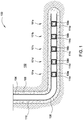
- Figure 1 illustrates an embodiment of a stimulation system 100 for selectively isolating and/or stimulating a plurality of zones 101a-e of a wellbore 106 in a formation 102.
- the zones 101a-e are spaced axially along the wellbore 106.
- the zones 101a-e may correspond to areas in the formation 102 with a potential for yielding production fluid.
- the stimulation system 100 includes a tubular 104 lowered into the wellbore 106, thereby creating an annulus 108 in the space therebetween.
- the tubular 104 or 203 is used to indicate any type of tubular, mandrel, string, and/or sub strings, and such used alone or in combination to transport fluid to and from the wellbore 106.
- the annulus 108 may be sealed using cement 110 or another suitable, hardenable substance in order to reduce or prevent fluid communication between the zones 101a-e via the annulus 108. Alternatively, the annulus 108 may be sealed using packers or other sealing materials.
- the stimulation system 100 includes an isolation tool 109 and a port 114 in each zone 101a-e.
- a plurality of isolation tools 109a-e and ports 114a-e are spaced axially along the tubular 104.
- Figure 1 illustrates five isolation tools 109 in the stimulation system 100, any appropriate number of isolation tools 109, and as many ports 114, may be used in conjunction with the system and method of the present disclosure.
- two or more isolation tools may be positioned in a single zone, or one isolation tool may serve two or more zones.
- the isolation tools 109 in the stimulation system 100 are used to control the placement of an injected fluid.
- the isolation tools 109 are used in a cementing operation to inject cement 110 into the annulus 108.
- the isolation tools 109 are used in a stimulation operation to inject stimulation or frac fluid into the formation 102.
- the isolation tools 109 are used to inject any suitable fluid into the formation 102, such as water, gas, or steam.
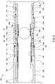
- Figure 2 is a cross sectional view of an exemplary embodiment of an isolation tool 209.
- the isolation tool 209 is shown with an actuating member 202, such as a ball 202a, disposed therein.
- the isolation tool 209 includes a tubular 203, a closure member 206, a first sleeve member 208, and a second sleeve member 210.
- the tubular 203 includes the port 114, a mandrel 204, and a bore 214 extending through the tubular 203.
- the mandrel 204 includes a recess 207 and a plurality of grooves 219a-d on an inner surface 205.
- the closure member 206 such as a flapper valve 206, is disposed in the recess 207 of the mandrel 204 while the flapper valve 206 is in an open position. In the open position, the flapper valve 206 permits fluid communication through the bore 214 of the tubular 203.
- the flapper valve 206 may include a biasing member, such as a spring, which biases the flapper valve 206 towards a closed position, wherein the flapper valve 206 blocks fluid communication through the bore 214 of the tubular 203.
- the spring is a torsion spring located at a hinge of the flapper valve 206.
- the first sleeve member 208 and the second sleeve member 210 are disposed in the bore 214 of the tubular 203.
- the first sleeve member 208 such as upper sliding sleeve 208, and an engagement sleeve 215 having a first end 221a and a second end 221b are integrally formed.
- the upper sliding sleeve 208 is operatively coupled to the engagement sleeve 215.
- the engagement sleeve 215 includes at least one engagement member 217, such as a dog 217.
- Each dog 217 protrudes through a corresponding slot 223 in the upper sliding sleeve 208, thereby operatively connecting the upper sliding sleeve 208 and the engagement sleeve 215.
- movement of the engagement sleeve 215 in the axial direction moves the upper sliding sleeve 208 in the same direction.
- the dogs 217 interact with the inner surface 205 to control movement of the upper sliding sleeve 208.
- the dogs 217 extend through the slots 223 in the upper sliding sleeve 208 and slide along the inner surface 205.
- the dogs 217 are biased radially outwards from a center of the bore 214.
- the dogs 217 are spring-loaded and biased against the inner surface 205.
- the dogs 217 when the dogs 217 are axially aligned with the grooves 219a, 219b, the dogs 217 sequentially extend into the grooves 219a, 219b and avoid obstructing the bore 214. Initially, the dogs 217 extend into groove 219a, as shown in Figure 2 . When the engagement sleeve 215 moves downwards, the dogs 217 move downwards. The dogs 217 moves out of the groove 219a and onto the inner surface 205 of the mandrel 204, thereby moving radially towards the center of the bore 214. As a result, the dogs 217 partially obstruct the bore 214 and form a seat for receiving the actuating member 202.
- the engagement sleeve 215 also includes at least one locking member, each of which is biased radially outwards from the center of the bore 214.
- the locking member is a dog biased radially outward by a biasing member, such as a spring.
- the locking member is a snap ring biased radially outward.
- the locking member is a lock ring 220 biased radially outward. The lock ring 220 moves between a retracted position, wherein the lock ring 220 is disposed in a groove formed in the engagement sleeve 215, and an extended position, wherein the lock ring 220 extends into the grooves 219c, 219d of the mandrel 204.
- the lock ring 220 is in the retracted position, as shown in Figure 2 .
- the lock ring 220 engages the inner surface 205 of the mandrel 204.
- the lock ring 220 moves downwards and extends into the groove 219c.
- the lock ring 220 resists downward movement of the engagement sleeve 215 up to a threshold force in the downward direction.
- the lock ring 220 is biased into the grooves 219c, 219d such that the lock ring 220 retracts when the ball 202a indirectly exerts a downward force on the engagement sleeve 215 via the dogs 217 equal to or greater than the threshold force of the lock ring 220 .
- the lock ring 220 retracts and subsequently extends into the groove 219d.
- the upper sliding sleeve 208 restricts movement of the flapper valve 206 from the open position ( Figure 2 ) to the closed position ( Figure 8 ).
- the upper sliding sleeve 208 at least partially covers the flapper valve 206 such that the flapper valve 206 cannot rotate at the hinge.
- the upper sliding sleeve 208 is biased away from the flapper valve 206 by a biasing member 216.
- the biasing member 216 such as a spring 216, is disposed between a shoulder 218 of the mandrel 204 and the first end 221a of the engagement sleeve 215.
- the spring 216 is configured to bias the engagement sleeve 215 and the upper sliding sleeve 208 downwards. Downward movement of the engagement sleeve 215 is restricted by the second sleeve member 210, such as a lower sliding sleeve 210.
- the lower sliding sleeve 210 is movable from a closed position ( Figure 2 ) to an open position ( Figure 7 ). In the closed position, the second end 221b of the engagement sleeve 215 abuts the lower sliding sleeve 210.
- the lower sliding sleeve 210 is configured so that a downward force provided by the spring 216 is insufficient to move the engagement sleeve 215 and the lower sliding sleeve 210 downwards.
- a frangible member 222 such as a shear ring 222, may hold the lower sliding sleeve 210 in the closed position and prevent the lower sliding sleeve 210 from moving downwards.
- the shear ring 222 shears at a threshold force in the downward direction.
- the downward force of the spring 216 is set to less than the threshold force of the shear ring 222 to prevent premature movement of the lower sliding sleeve 210 from the closed position.
- the lower sliding sleeve 210 reduces or blocks fluid communication between the bore 214 of the tubular 203 and the port 114.
- the lower sliding sleeve 210 covers the port 114 such that fluid communication between the bore 214 and the port 114 is blocked.
- the lower sliding sleeve 210 includes a counting mechanism 212 and a plurality of grooves 224a-g spaced axially along an inner surface 211 of the lower sliding sleeve 210, as shown in Figure 2 .
- the counting mechanism 212 counts the number of actuating members 202 passing through the bore 214 of the isolation tool 209 during a counting operation.
- the counting operation includes a plurality of counts. A count begins when the counting mechanism 212 receives the actuating member 202 in a seat formed by the counting mechanism 212.
- the actuating member 202 moves the counting mechanism 212 relative to the lower sliding sleeve 210 until the actuating member is no longer seated in the counting mechanism 212.
- each actuating member 202 is the same size.
- each ball 202 has the same diameter.
- the counting mechanism 212 includes a counter sleeve 225 with a plurality of alternating engagement members, such as upper and lower ball bearings 226a, 226b arranged circumferentially about the counter sleeve 225.
- the engagement members are dogs biased radially outward by a biasing member, such as a spring.
- the counting mechanism 212 also includes a plurality of alternating locking members, such as upper and lower snap rings 228a, 228b.
- the locking members are lock rings.
- the grooves 224a-g are circumferentially arranged on an inner surface of the lower sliding sleeve 210. The grooves 224a-g are configured to receive the engagement members and locking members of the counting mechanism 212.
- the ball bearings 226a, 226b are free-floating between the counter sleeve 225 and the lower sliding sleeve 210.
- the snap rings 228a, 228b may be biased radially outwards from the center of the bore 214.
- the snap rings 228a, 228b control the downward advancement of the counter sleeve 225.
- the snap rings 228a, 228b each include ramped lead edges to facilitate advancement out of the grooves 224a-g.
- the snap rings 228a, 228b alternatingly move between an extended position and a retracted position. In the retracted position, the snap rings 228a, 228b are disposed in respective grooves formed in the counter sleeve 225 and engage the inner surface 211. In the extended position, the snap rings 228a, 228b move into respective grooves 224a-g in the lower sliding sleeve 210.
- the snap rings 228a, 228b resist downward movement of the counter sleeve 225 relative to the lower sliding sleeve 210 up to a threshold force.
- the upper snap ring 228a is in the extended position at groove 224b and the lower snap ring 228b is in the retracted position, as shown in Figure 2 .
- the upper snap ring 228a resists downward movement of the counter sleeve 225 up to the threshold force of the upper snap ring 228a.
- the upper snap ring 228a retracts and the counter sleeve 225 moves downwards.
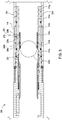
- the lower snap ring 228b subsequently moves into the extended position at groove 224c and the upper snap ring 228a moves into the retracted position, as shown in Figure 3 . Thereafter, the lower snap ring 228b resists downward movement of the counter sleeve 225 up to the threshold force of the lower snap ring 228b.
- sequentially moving the counter sleeve 225 axially downwards in the tubular 203 sequentially moves the ball bearings 226a, 226b and the snap rings 228a, 228b into and out of the grooves 224a-g.
- the ball bearings 226a, 226b are configured to form alternating seats when the counter sleeve 225 moves downwards.
- the upper ball bearings 226a can move into the groove 224a while the lower ball bearings 226b move onto the inner surface 211, as shown in Figure 2 .
- the lower ball bearings 226b are forced radially inwards to partially obstruct the bore 214.
- the lower ball bearings 226b form a seat for the ball 202a.
- the upper and lower ball bearings 226a, 226b move downwards.
- the upper ball bearings 226a move onto the inner surface 211 and the lower ball bearings 226b move into the groove 224b, as shown in Figure 3 .
- the upper ball bearings 226a are forced radially inwards to partially obstruct the bore 214.
- the upper ball bearings 226a form a seat.
- the isolation tool 209 shows a single upper sliding sleeve 208, lower sliding sleeve 210, counting mechanism 212, flapper valve 206, and port 114, it is contemplated that any appropriate number of upper sliding sleeves, lower sliding sleeves, counting mechanisms, flapper valves, ports, and corresponding features may be used in the isolation tool 209.
- the counting operation begins by releasing the ball 202a into the tubular 104.
- the ball 202a moves downwards in the tubular 104 until the ball 202a engages the counting mechanism 212.
- the ball 202a engages the counting mechanism 212 by landing on a seat formed by the lower ball bearings 226b, as shown in Figure 2 . This begins a first count.
- the ball 202a moves the counter sleeve 225 downwards.
- a downward force produced by the momentum of the ball 202a plus a fluid force behind the ball 202a is equal to or greater than the threshold force of the upper snap ring 228a.
- the ball 202a causes the upper snap ring 228a to retract, which allows the counter sleeve 225 to move downwards.
- the fluid force behind the ball 202a is increased after the ball 202a lands in the counting mechanism 212 in order to produce a downward force equal to or greater than the threshold force of the upper snap ring 228a.
- the threshold force of the upper snap ring 228a is set lower than the threshold force of the shear ring 222. As such, the ball 202a causes the upper snap ring 228a to retract without causing the shear ring 222 to shear.
- the counter sleeve 225 travels downwards until the lower snap ring 228b extends into the groove 224c, as shown in Figure 3 .
- the lower ball bearings 226b move into the groove 224b and the upper ball bearings 226a move onto the inner surface 211 of the lower sliding sleeve 210.
- the upper ball bearings 226a form a seat for a next ball 202b.
- the lower ball bearings 226b which served as the seat for the ball 202a, no longer form the seat.
- the ball 202a is released from the counting mechanism 212. This completes the first count. Thereafter, the ball 202a is allowed to move downwards out of the isolation tool 209 and engage other tools downhole.
- the ball 202b is released into the tubular 104.
- the ball 202b moves downwards in the tubular 104 and engages the counting mechanism 212.
- the ball 202b engages the counting mechanism 212 by landing on the seat formed by the upper ball bearings 226a, as shown in Figure 3 . This begins a first half of the second count.
- the ball 202b moves the counter sleeve 225 downwards.
- a downward force produced by the momentum of the ball 202b plus a fluid force behind the ball 202b is equal to or greater than the threshold force of the lower snap ring 228b.
- the ball 202b causes the lower snap ring 228b to retract, which allows the counter sleeve 225 to move downwards.
- the fluid force behind the ball 202b is increased after the ball 202b lands in the counting mechanism 212 in order to produce a downward force equal to or greater than the threshold force of the lower snap ring 228b.
- the threshold force of the lower snap ring 228b is set lower than the threshold force of the shear ring 222.
- the ball 202b causes the lower snap ring 228b to retract without causing the shear ring 222 to shear.
- the counter sleeve 225 moves downwards until the upper snap ring 228a moves into the groove 224c, as shown in Figure 4 .
- the upper ball bearings 226a which initially served as the seat for the ball 202b during the first half of the second count, move into the groove 224b and no longer form the seat. In turn, the ball 202b is released from the upper ball bearings 226a. This completes the first half of a second count.
- the ball 202b After the ball 202b is released from the upper ball bearings 226a, the ball 202b lands in a seat formed by the lower ball bearings 226b, as shown in Figure 4 . This begins a second half of the second count.
- the ball 202b continues to move the counter sleeve 225 downwards relative to the lower sliding sleeve 210 by causing the retraction of the upper snap ring 228a.
- the downward force produced by the momentum of the ball 202b plus the fluid force behind the ball 202b is equal to or greater than the threshold force of the upper snap ring 228a.
- the ball 202b causes the upper snap ring 228a to retract, which allows the counter sleeve 225 to continue moving downwards.
- the fluid force behind the ball 202b is increased after the ball 202b lands in the counting mechanism 212 in order to produce a downward force equal to or greater than the threshold force of the upper snap ring 228a.
- the counter sleeve 225 travels downwards until the lower snap ring 228b extends into the groove 224d, as shown in Figure 5 .
- the lower ball bearings 226b move into the groove 224c and the upper ball bearings 226a move onto the inner surface 211 of the lower sliding sleeve 210.
- the upper ball bearings 226a form a seat for a next ball 202c.
- the lower ball bearings 226b which served as the seat for the ball 202b, no longer form the seat.
- the ball 202b is released from the counting mechanism 212. This completes the second half of the second count. Thereafter, the ball 202b is allowed to move downwards out of the isolation tool 209 and engage other tools downhole.
- the counting mechanism 212 subsequently receives the ball 202c in the seat formed by the upper ball bearings 226a, as shown in Figure 5 . This begins a first half of a third count.
- the ball 202c moves the counter sleeve 225 downwards by first seating on the upper ball bearings 226a and then seating on the lower ball bearings 226b, similar to the second count using the ball 202b.
- the counter sleeve 225 moves downwards until lower snap ring 228b extends into the groove 224e.
- the lower ball bearings 226b move into the groove 224d and release the ball 202c. This completes the third count.
- the third count represents a final count of the counting operation.
- the counting operation is completed when the final count is completed.
- the counting mechanism 212 is in an actuating position. In other words, the next ball 202 to land in the counting mechanism 212 will actuate the lower sliding sleeve 210 into the open position.
- the lower sliding sleeve 210 may include any appropriate number of grooves in order to lengthen or shorten the counting operation.
- the counting operation may be lengthened or shortened by selecting a starting position of the counter sleeve 225 on the lower sliding sleeve 210.
- the number of balls 202 counted by the counting mechanism 212 is increased by increasing the number of grooves 224 in the counter sleeve 225 and/or by positioning the counter sleeve 225 towards an upper end of the lower sliding sleeve 210.
- the ball 202d is released into the tubular 104.
- the ball 202d is released into the tubular 104 to actuate the lower sliding sleeve 210 from the closed position to the open position.
- the ball 202d lands in the seat formed by the upper ball bearings 226a. Similar to the preceding balls 202a-c, the downward force of the ball 202d causes the lower snap ring 228b to retract, thereby allowing the counter sleeve 225 to move downwards.
- the counter sleeve 225 moves downwards until the upper and lower snap rings 228a, 228b extend into respective grooves 224e, 224f, as shown in Figure 6 .
- the upper ball bearings 226a move into the groove 224d, thereby releasing the ball 202d.
- the ball 202d lands in a seat formed by the lower ball bearings 226b.
- a force equal to or greater than the combined threshold force of the upper and lower snap rings 228a, 228b is required to move the counter sleeve 225.
- the combined threshold force of the upper and lower snap rings 228a, 228b is set to be equal to or greater than the threshold force required to shear the shear ring 222.
- the ball 202d continues urge the counter sleeve 225 downwards by exerting a downward force on the seat formed by the lower ball bearings 226b.
- the downward force produced by the momentum of the ball 202d plus a fluid force behind the ball 202d is equal to or greater than the combined threshold force of the upper and lower snap rings 228a, 228b.
- the fluid force behind the ball 202d is increased after the ball 202d lands in the counting mechanism 212 in order to produce a downward force equal to or greater than the combined threshold force of the upper and lower snap rings 228a, 228b.
- the ball 202d causes both the upper and lower snap rings 228a, 228b to retract, which allows the counter sleeve 225 to move downwards. Because the combined threshold force of the upper and lower snap rings 228a, 228b is equal to or greater than the threshold force of the shear ring 222, the downward force of the ball 202d also causes the shear ring 222 to shear. As a result, the lower sliding sleeve 210 is allowed to move towards the open position, as shown in Figure 7 . For example, the lower sliding sleeve 210 moves towards the open position by sliding downward.
- the counter sleeve 225 moves downwards relative to the lower sliding sleeve 210 until the upper and lower snap rings 228a, 228b extend into respective grooves 224f, 224g, as shown in Figure 7 .
- the upper ball bearings 226a move onto the inner surface 211 and form a seat for a next ball 202e.
- the lower ball bearings 226b move into the groove 224e, thereby releasing the ball 202d from the counting mechanism 212. Thereafter, the ball 202d is allowed to act on other tools downhole.
- the lower sliding sleeve 210 In the open position, the lower sliding sleeve 210 allows fluid communication between the bore 214 and the port 114. In one embodiment, the lower sliding sleeve 210 abuts a shoulder 302 in the tubular 203 when the lower sliding sleeve 210 is in the open position. The shoulder 302 prevents further downward movement of the lower sliding sleeve 210.
- Movement of the lower sliding sleeve 210 from the closed position to the open position disengages the second end 221b of the engagement sleeve 215 from the lower sliding sleeve 210.
- the engagement sleeve 215 is allowed to move a distance downward.
- the spring 216 exerts a force against the first end 221a of the engagement sleeve 215 to move the engagement sleeve 215 downward.
- both the dogs 217 and the lock ring 220 on the engagement sleeve 215 also move downward.
- the lock ring 220 stops the downward movement of the engagement sleeve 215 by extending into the groove 219c, as shown in Figure 7 .
- the lock ring 220 resists further downward movement of the engagement sleeve 215 up to the threshold force of the lock ring 220.
- the dogs 217 move onto the inner surface 205 of the mandrel 204 and form a seat configured to receive a subsequent actuating member, such as the ball 202e.
- the flapper valve 206 remains in the open position after the lower sliding sleeve 210 moves to the open position, as shown in Figure 7 .
- the lock ring 220 limits the downward movement of the engagement sleeve 215 such that the upper sliding sleeve 208 at least partially covers the flapper valve 206. Consequently, the flapper valve 206 cannot move into the closed position by rotating around the hinge.
- an injection operation may be performed through the port 114.
- the injection operation may include injecting fluid such as water, gas, steam, stimulation or frac fluid into the formation 102 via the port 114.
- the flapper 206 is moved to the closed position such that injection operations may be conducted in isolation tools further uphole.
- the ball 202e may be released into the tubular 104 to actuate the flapper valve 206 into the closed position.
- the ball 202e arrives in the isolation tool 209, it lands in the seat formed by the dogs 217.
- the ball 202e moves the dogs 217 downward until the dogs 217 extend into the groove 219b, thereby releasing the ball 202e from the upper sliding sleeve 208.
- the ball 202e causes the lock ring 220 to move into the groove 219d and thus prevent further downward movement of the engagement sleeve 215.
- the ball 202e By moving the dogs 217 downwards, the ball 202e also moves the engagement sleeve 215 and upper sliding sleeve 208 downwards.
- the upper sliding sleeve 208 moves sufficiently downwards to fully uncover the flapper valve 206 such that the flapper valve 206 freely rotates to the closed position.
- the flapper valve 206 rotates out of the recess 207 to sealingly engage a flapper seat 402, as shown in Figure 8 .
- the ball 202e continues moving downwards until the ball 202e lands on the seat formed by the upper ball bearings 226a. In the closed position, the flapper valve 206 blocks fluid communication through the bore 214 of the tubular 203. With the flapper valve 206 blocking the bore 214, fluid may no longer be injected into the formation 102 via the port 114.
- a stimulation tool having a plurality of isolation tools may be used in the injection operation.
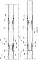
- first and second isolation tools 809a, 809b are disposed in respective zones 801a, 801b, as shown in Figure 9 .
- the isolation tools 809a, 809b and the zones 801a, 801b may be located at any depth in the tubular 104.
- any appropriate number of isolation tools 809 may be located above or below the isolation tools 809a, 809b.
- the components on the isolation tools 809a, 809b that are similar to the components on the isolation tool 209 are labeled with the same reference indicator and a letter, such as an "a" or "b", indicating components further downhole or uphole, respectively.
- isolation tool 809b is located uphole from isolation tool 809a.
- the counting mechanism 212 in each isolation tool 809 is configured such that each counting mechanism 212 is on a count preceding the count in the isolation tool immediately below (downhole) the respective isolation tool 809. For example, the counting mechanism 212b is on a second count when the counting mechanism 212a is on a third count.
- the counting mechanism 212 in each isolation tool 809 is also configured such that each counting mechanism 212 is in the actuating position when the lower sliding sleeve 210 immediately below the respective isolation tool 809 moves into the open position. For example, the counting mechanism 212b in the isolation tool 809b is in the actuating position when the lower sliding sleeve 210a in the isolation tool 809a is in the open position.
- a ball 802a is released into the tubular 104, as with ball 202a in Figure 2 .
- the ball 802a is released after opening circulation at a toe of the tubular 104.
- the ball 802a may pass through multiple tools in the tubular 104.
- the ball 802a passes through multiple isolation tools 809, each having a counting mechanism 212 configured to count an appropriate number of balls 802 before moving the lower sliding sleeve 210 to the open position.
- the ball 802a lands in the counting mechanism 212b, which is on a third and final count.
- the counting mechanism 212b completes the third count, thereby moving downward and releasing the ball 802a.
- the counting mechanism 212b is in the actuating position.
- the ball 802a continues traveling downwards and lands in the counting mechanism 212a, which is in the actuating position.
- the ball 802a causes the counting mechanism 212a to move downwards, thereby shearing the shear ring 222a and actuating the lower sliding sleeve 210a into the open position, as shown in Figure 9 .
- the ball 802a is released from the counting mechanism 212a and continues traveling downhole to provide a pressure buildup in the tubular 104.
- the ball 802a continues downhole and actuates a flapper valve 206 in an isolation tool 809 below the isolation tool 809a.
- the ball 802a continues downhole and sealingly plugs a single-shot valve below the isolation tool 809a. In yet another embodiment, the ball 802a continues downhole and closes a flapper valve below isolation tool 809a. Thereafter, fluid may be injected through port 114a.
- a ball 802b is released into the tubular 104.
- the ball 802b may pass through multiple isolation tools 809 and land in the counting mechanism 212b, as shown in Figure 9 .
- the ball 802b causes the counting mechanism 212b to move downwards, thereby shearing the shear ring 222b and actuating the lower sliding sleeve 210b into the open position, as shown in Figure 10 .
- the counting mechanism 212b subsequently releases the ball 802b and the ball 802b continues downwards towards the isolation tool 809a.
- the ball 802b lands in the upper sliding sleeve 208a ( Figure 10 ) and moves the upper sleeve 208a downwards, thereby actuating the flapper valve 206a into the closed position ( Figure 11 ).
- the flapper valve 206a blocks fluid communication through the bore 214a. Thereafter, fluid may be injected into port 114b.
- Ball 802b thereby, actuates both lower sliding sleeve 210b into the open position and flapper valve 206a into the closed position.
- the ball 802b is released from the upper sliding sleeve 208a and prevented from moving into another zone 801.
- the flapper 206a prevents the ball 802b from moving uphole.
- the seat formed by the counting mechanism 212a prevents the ball 802b from moving downhole.
- a ball 802c is released into the tubular 104.
- the ball 802c may pass through multiple isolation tools 809 and land in the upper sliding sleeve 208b, as shown in Figure 11 .
- the ball 802c causes the upper sliding sleeve 208b to move downwards, thereby actuating the flapper valve 206b into the closed position. Thereafter, similar to the ball 802b, the ball 802c is prevented from moving into another zone 801.
- the process of moving respective lower sliding sleeves 210, upper sliding sleeves 208, and flapper valves 206 may be repeated one or more times by releasing one or more subsequent balls 802 into the tubular 104 to engage one or more isolation tools 809 uphole. As such, multiple zones 801 may be sequentially isolated using balls 802 of the same size.
- a stimulation tool in one embodiment, includes a tubular having a port; a first sleeve member disposed in the tubular and actuatable by an actuating member to move from a closed position wherein fluid communication between a bore of the tubular and the port is blocked; and a closure member disposed in the tubular and actuatable by the actuating member to a closed position wherein fluid communication through the bore of the tubular is blocked.
- the actuating member is a ball.
- the closure member is a flapper valve.
- the first sleeve member includes a first seat configured to receive and release the actuating member
- the tool further comprising a second sleeve member disposed in the tubular, the second sleeve member includes a second seat configured to receive the actuating member, and the closure member is actuatable by the second sleeve member when the second seat receives the actuating member.
- the first seat is configured to receive and release a second actuating member
- the second seat is configured to receive and release the second actuating member
- the closure member is downhole from the port.
- the first seat is configured to receive a third actuating member
- the tool further comprising a second closure member disposed in the tubular and actuatable by the third actuating member to a closed position wherein fluid communication through the bore of the tubular is blocked, the second closure member is actuatable by the first sleeve member when the first seat receives the third actuating member.
- the tool also includes a biasing member disposed in the tubular and configured to bias the second sleeve member away from the closure member.
- the second sleeve member includes engagement members.
- the engagement members include dogs that form the second seat.
- the engagement members are at least one of ball bearings and dogs.
- the second sleeve member includes locking members.
- the locking members are at least one of lock rings and snap rings.
- the first sleeve member blocks the port in the closed position.
- the first sleeve member includes a counting mechanism.
- the counting mechanism is slidable and includes alternating locking members.
- the locking members are at least one of lock rings and snap rings.
- the counting mechanism is slidable and includes alternating engagement members.
- the engagement members are at least one of ball bearings and dogs.
- the counting mechanism is slidable and includes alternating locking members and alternating engagement members.
- the second sleeve member includes a counting mechanism.
- the tubular has a second port
- the tool also includes a third sleeve member disposed in the tubular, wherein the third sleeve member includes a third seat and is actuatable to move from a closed position wherein fluid communication between a bore of the tubular and the second port is blocked; a fourth sleeve member disposed in the tubular, wherein the fourth sleeve member includes a fourth seat; and a third closure member disposed in the tubular and actuatable by the fourth sleeve to a closed position wherein fluid communication through the bore of the tubular is blocked.
- a multi-zone stimulation assembly in one embodiment, includes a tubular a tubular having a first port, a second port, and a bore therethrough; a first sleeve member having a first seat, the first sleeve member configured to selectively allow fluid communication through the first port; a third sleeve member having a third seat; and a closure member disposed between the first and second ports and actuatable by the third sleeve member to a closed position wherein fluid communication is blocked through the bore of the tubular.
- the assembly also includes a second sleeve member having a second seat, the second sleeve member configured to selectively allow fluid communication through the second port.
- the first seat and the second seat are the same size.
- the first sleeve member and second sleeve members each include a counting mechanism.
- the third sleeve member includes a counting mechanism.
- the third sleeve member includes at least one engagement member movable into the bore of the tubular to form the third seat.
- the third sleeve member is actuated by the second sleeve member.
- a method of stimulating multiple zones of a tubular in a wellbore includes moving a sleeve member in the tubular by receiving an actuating member in the sleeve member; releasing the actuating member from the sleeve member; and actuating a closure member by receiving the released actuating member in a seat.
- the actuating member is a ball.
- the closure member is a flapper valve.
- the method also includes forming the seat.
- forming the seat comprises releasing a second actuating member into the tubular.
- the second actuating member is released into the tubular before the sleeve member receives the actuating member.
- At least one dimension of the actuating member is equal to at least one dimension of the second actuating member.
- the second actuating member passes through the sleeve member before the seat is formed.
- forming the seat includes moving at least one engagement member into a bore of the tubular.
- actuating the closure member blocks fluid communication through a bore of the tubular.
- moving the sleeve member allows fluid communication between a bore of the tubular and a port in the tubular.
- receiving the actuating member includes engaging the actuating member with a seat in the sleeve member.
- the method also includes forming a second seat by moving the sleeve member.
- the actuating member passes through the sleeve member before actuating the closure member.
- a momentum of the actuating member moves the sleeve member.
- the method also includes pumping fluid through the port.
Landscapes
- Life Sciences & Earth Sciences (AREA)
- Engineering & Computer Science (AREA)
- Geology (AREA)
- Mining & Mineral Resources (AREA)
- Physics & Mathematics (AREA)
- Environmental & Geological Engineering (AREA)
- Fluid Mechanics (AREA)
- General Life Sciences & Earth Sciences (AREA)
- Geochemistry & Mineralogy (AREA)
- Quick-Acting Or Multi-Walled Pipe Joints (AREA)
Applications Claiming Priority (2)
| Application Number | Priority Date | Filing Date | Title |
|---|---|---|---|
| US201562156757P | 2015-05-04 | 2015-05-04 | |
| EP16167792.7A EP3093428B1 (fr) | 2015-05-04 | 2016-04-29 | Outil de stimulation à double manchon |
Related Parent Applications (1)
| Application Number | Title | Priority Date | Filing Date |
|---|---|---|---|
| EP16167792.7A Division EP3093428B1 (fr) | 2015-05-04 | 2016-04-29 | Outil de stimulation à double manchon |
Publications (1)
| Publication Number | Publication Date |
|---|---|
| EP3567210A1 true EP3567210A1 (fr) | 2019-11-13 |
Family
ID=55862660
Family Applications (2)
| Application Number | Title | Priority Date | Filing Date |
|---|---|---|---|
| EP19176130.3A Withdrawn EP3567210A1 (fr) | 2015-05-04 | 2016-04-29 | Outil de stimulation à double manchon |
| EP16167792.7A Active EP3093428B1 (fr) | 2015-05-04 | 2016-04-29 | Outil de stimulation à double manchon |
Family Applications After (1)
| Application Number | Title | Priority Date | Filing Date |
|---|---|---|---|
| EP16167792.7A Active EP3093428B1 (fr) | 2015-05-04 | 2016-04-29 | Outil de stimulation à double manchon |
Country Status (4)
| Country | Link |
|---|---|
| US (1) | US9970260B2 (fr) |
| EP (2) | EP3567210A1 (fr) |
| AU (1) | AU2016202840B2 (fr) |
| CA (1) | CA2928648A1 (fr) |
Families Citing this family (9)
| Publication number | Priority date | Publication date | Assignee | Title |
|---|---|---|---|---|
| WO2015094241A1 (fr) * | 2013-12-18 | 2015-06-25 | Halliburton Energy Services Inc. | Dispositif décélérateur pour outils de fond de trou activés par une bille |
| DE112017007572T5 (de) * | 2017-08-03 | 2020-02-27 | Halliburton Energy Services, Inc. | Bohrlochfluidkommunikationswerkzeug |
| US10400555B2 (en) * | 2017-09-07 | 2019-09-03 | Vertice Oil Tools | Methods and systems for controlling substances flowing through in an inner diameter of a tool |
| CN110145292B (zh) * | 2019-05-18 | 2022-03-08 | 中国石油天然气股份有限公司 | 一种弹性锁套喷砂器 |
| CN111021973B (zh) * | 2019-12-18 | 2023-10-31 | 中国石油天然气股份有限公司 | 一种捕收球式适配器及其安装方法 |
| US11927067B2 (en) | 2021-11-30 | 2024-03-12 | Baker Hughes Oilfield Operations Llc | Shifting sleeve with extrudable ball and dog |
| US11814926B2 (en) | 2021-11-30 | 2023-11-14 | Baker Hughes Oilfield Operations Llc | Multi plug system |
| US11891869B2 (en) | 2021-11-30 | 2024-02-06 | Baker Hughes Oilfield Operations | Torque mechanism for bridge plug |
| US11891868B2 (en) * | 2021-11-30 | 2024-02-06 | Baker Hughes Oilfield Operations Llc | Extrusion ball actuated telescoping lock mechanism |
Citations (2)
| Publication number | Priority date | Publication date | Assignee | Title |
|---|---|---|---|---|
| GB2448632A (en) * | 2006-01-13 | 2008-10-22 | Schlumberger Holdings | Multi-State object activated valve with additional isolating member |
| US20140034294A1 (en) * | 2010-10-21 | 2014-02-06 | Summit Downhole Dynamics, Ltd. | Fracturing System and Method |
Family Cites Families (33)
| Publication number | Priority date | Publication date | Assignee | Title |
|---|---|---|---|---|
| US4469174A (en) * | 1983-02-14 | 1984-09-04 | Halliburton Company | Combination cementing shoe and basket |
| US6401824B1 (en) | 2000-03-13 | 2002-06-11 | Davis-Lynch, Inc. | Well completion convertible float shoe/collar |
| US7287596B2 (en) | 2004-12-09 | 2007-10-30 | Frazier W Lynn | Method and apparatus for stimulating hydrocarbon wells |
| US7387165B2 (en) | 2004-12-14 | 2008-06-17 | Schlumberger Technology Corporation | System for completing multiple well intervals |
| US7322417B2 (en) * | 2004-12-14 | 2008-01-29 | Schlumberger Technology Corporation | Technique and apparatus for completing multiple zones |
| US7581596B2 (en) | 2006-03-24 | 2009-09-01 | Dril-Quip, Inc. | Downhole tool with C-ring closure seat and method |
| US7661478B2 (en) | 2006-10-19 | 2010-02-16 | Baker Hughes Incorporated | Ball drop circulation valve |
| US20090308588A1 (en) | 2008-06-16 | 2009-12-17 | Halliburton Energy Services, Inc. | Method and Apparatus for Exposing a Servicing Apparatus to Multiple Formation Zones |
| WO2010127457A1 (fr) | 2009-05-07 | 2010-11-11 | Packers Plus Energy Services Inc. | Raccord double femelle de manchon coulissant et procédé et appareil de traitement de fluide de puits de forage |
| US8261761B2 (en) | 2009-05-07 | 2012-09-11 | Baker Hughes Incorporated | Selectively movable seat arrangement and method |
| US20100294514A1 (en) | 2009-05-22 | 2010-11-25 | Baker Hughes Incorporated | Selective plug and method |
| US20100294515A1 (en) | 2009-05-22 | 2010-11-25 | Baker Hughes Incorporated | Selective plug and method |
| US8272445B2 (en) | 2009-07-15 | 2012-09-25 | Baker Hughes Incorporated | Tubular valve system and method |
| US8291988B2 (en) * | 2009-08-10 | 2012-10-23 | Baker Hughes Incorporated | Tubular actuator, system and method |
| US8479823B2 (en) | 2009-09-22 | 2013-07-09 | Baker Hughes Incorporated | Plug counter and method |
| US8403068B2 (en) | 2010-04-02 | 2013-03-26 | Weatherford/Lamb, Inc. | Indexing sleeve for single-trip, multi-stage fracing |
| US8505639B2 (en) | 2010-04-02 | 2013-08-13 | Weatherford/Lamb, Inc. | Indexing sleeve for single-trip, multi-stage fracing |
| US8789600B2 (en) | 2010-08-24 | 2014-07-29 | Baker Hughes Incorporated | Fracing system and method |
| US9562419B2 (en) * | 2010-10-06 | 2017-02-07 | Colorado School Of Mines | Downhole tools and methods for selectively accessing a tubular annulus of a wellbore |
| US8991505B2 (en) * | 2010-10-06 | 2015-03-31 | Colorado School Of Mines | Downhole tools and methods for selectively accessing a tubular annulus of a wellbore |
| US9664015B2 (en) * | 2010-10-21 | 2017-05-30 | Peak Completion Technologies, Inc. | Fracturing system and method |
| EP2880252A2 (fr) | 2012-07-31 | 2015-06-10 | Petrowell Limited | Appareil de fond de trou et procédé |
| RU2655074C2 (ru) | 2012-12-04 | 2018-05-23 | ВЕЗЕРФОРД ТЕКНОЛОДЖИ ХОЛДИНГЗ, ЭлЭлСи | Скважинное устройство и способ |
| GB201304790D0 (en) | 2013-03-15 | 2013-05-01 | Petrowell Ltd | Catching apparatus |
| GB201304769D0 (en) | 2013-03-15 | 2013-05-01 | Petrowell Ltd | Shifting tool |
| GB201304825D0 (en) | 2013-03-15 | 2013-05-01 | Petrowell Ltd | Downhole arrangement |
| GB201304771D0 (en) | 2013-03-15 | 2013-05-01 | Petrowell Ltd | Heat treat production fixture |
| GB201304801D0 (en) | 2013-03-15 | 2013-05-01 | Petrowell Ltd | Downhole apparatus |
| US8863853B1 (en) | 2013-06-28 | 2014-10-21 | Team Oil Tools Lp | Linearly indexing well bore tool |
| CN203603846U (zh) | 2013-11-15 | 2014-05-21 | 中国石油化工股份有限公司 | 用于油气井作业的全通径分层压裂滑套 |
| CN203847089U (zh) | 2014-05-23 | 2014-09-24 | 湖南唯科拓石油科技服务有限公司 | 计数装置及多级全通径投球滑套装置 |
| WO2016022120A1 (fr) * | 2014-08-07 | 2016-02-11 | Halliburton Energy Services, Inc. | Système d'actionnement multi-zone utilisant des projectiles de puits de forage et des soupapes à clapet |
| CA2911551C (fr) * | 2014-11-07 | 2020-03-24 | Dick S. GONZALEZ | Manchon de stimulation d'indexation et autres outils de fond de trou |
-
2016
- 2016-04-29 CA CA2928648A patent/CA2928648A1/fr not_active Abandoned
- 2016-04-29 EP EP19176130.3A patent/EP3567210A1/fr not_active Withdrawn
- 2016-04-29 EP EP16167792.7A patent/EP3093428B1/fr active Active
- 2016-05-03 AU AU2016202840A patent/AU2016202840B2/en not_active Ceased
- 2016-05-04 US US15/146,053 patent/US9970260B2/en not_active Expired - Fee Related
Patent Citations (2)
| Publication number | Priority date | Publication date | Assignee | Title |
|---|---|---|---|---|
| GB2448632A (en) * | 2006-01-13 | 2008-10-22 | Schlumberger Holdings | Multi-State object activated valve with additional isolating member |
| US20140034294A1 (en) * | 2010-10-21 | 2014-02-06 | Summit Downhole Dynamics, Ltd. | Fracturing System and Method |
Also Published As
| Publication number | Publication date |
|---|---|
| US9970260B2 (en) | 2018-05-15 |
| AU2016202840A1 (en) | 2016-11-24 |
| US20160326836A1 (en) | 2016-11-10 |
| CA2928648A1 (fr) | 2016-11-04 |
| AU2016202840B2 (en) | 2017-07-13 |
| EP3093428B1 (fr) | 2019-05-29 |
| EP3093428A1 (fr) | 2016-11-16 |
Similar Documents
| Publication | Publication Date | Title |
|---|---|---|
| EP3093428B1 (fr) | Outil de stimulation à double manchon | |
| US9874067B2 (en) | Sliding sleeve sub and method and apparatus for wellbore fluid treatment | |
| US9464506B2 (en) | Sliding sleeve valve and method for fluid treating a subterranean formation | |
| US10487626B2 (en) | Fracturing valve and fracturing tool string | |
| US10669830B2 (en) | Apparatus, systems and methods for multi-stage stimulation | |
| US10337288B2 (en) | Sliding sleeve having indexing mechanism and expandable sleeve | |
| RU2759114C1 (ru) | Система и способ многоступенчатой стимуляции скважин | |
| US9297234B2 (en) | Method and apparatus for wellbore control | |
| US9611722B2 (en) | Top down liner cementing, rotation and release method | |
| US9670751B2 (en) | Sliding sleeve having retrievable ball seat | |
| CA2873541A1 (fr) | Vanne de fracturation et train d'outils de fracturation | |
| US10119365B2 (en) | Tubular actuation system and method | |
| US11280160B2 (en) | Multi-zone hydraulic stimulation system |
Legal Events
| Date | Code | Title | Description |
|---|---|---|---|
| PUAI | Public reference made under article 153(3) epc to a published international application that has entered the european phase |
Free format text: ORIGINAL CODE: 0009012 |
|
| STAA | Information on the status of an ep patent application or granted ep patent |
Free format text: STATUS: THE APPLICATION HAS BEEN PUBLISHED |
|
| AC | Divisional application: reference to earlier application |
Ref document number: 3093428 Country of ref document: EP Kind code of ref document: P |
|
| AK | Designated contracting states |
Kind code of ref document: A1 Designated state(s): AL AT BE BG CH CY CZ DE DK EE ES FI FR GB GR HR HU IE IS IT LI LT LU LV MC MK MT NL NO PL PT RO RS SE SI SK SM TR |
|
| STAA | Information on the status of an ep patent application or granted ep patent |
Free format text: STATUS: REQUEST FOR EXAMINATION WAS MADE |
|
| 17P | Request for examination filed |
Effective date: 20200406 |
|
| RBV | Designated contracting states (corrected) |
Designated state(s): AL AT BE BG CH CY CZ DE DK EE ES FI FR GB GR HR HU IE IS IT LI LT LU LV MC MK MT NL NO PL PT RO RS SE SI SK SM TR |
|
| 111Z | Information provided on other rights and legal means of execution |
Free format text: AL AT BE BG CH CY CZ DE DK EE ES FI FR GB GR HR HU IE IS IT LT LU LV MC MK MT NL NO PL PT RO RS SE SI SK SM TR AL AT BE BG CH CY CZ DE DK EE ES FI FR GB GR HR HU IE IS IT LT LU LV MC MK MT NL NO PL PT RO RS SE SI SK SM TR Effective date: 20200511 |
|
| R11X | Information provided on other rights and legal means of execution (corrected) |
Free format text: AL AT BE BG CH CY CZ DE DK EE ES FI FR GB GR HR HU IE IS IT LT LU LV MC MK MT NL NO PL PT RO RS SE SI SK SM TR Effective date: 20200511 |
|
| 111Z | Information provided on other rights and legal means of execution |
Free format text: AL AT BE BG CH CY CZ DE DK EE ES FI FR GB GR HR HU IE IS IT LT LU LV MC MK MT NL NO PL PT RO RS SE SI SK SM TR AL AT BE BG CH CY CZ DE DK EE ES FI FR GB GR HR HU IE IS IT LT LU LV MC MK MT NL NO PL PT RO RS SE SI SK SM TR Effective date: 20200511 |
|
| STAA | Information on the status of an ep patent application or granted ep patent |
Free format text: STATUS: EXAMINATION IS IN PROGRESS |
|
| 17Q | First examination report despatched |
Effective date: 20210429 |
|
| STAA | Information on the status of an ep patent application or granted ep patent |
Free format text: STATUS: THE APPLICATION IS DEEMED TO BE WITHDRAWN |
|
| 18D | Application deemed to be withdrawn |
Effective date: 20210910 |