EP3566997A1 - Maintenance control system, people conveyor with maintenance control system and method of using maintenance control system - Google Patents
Maintenance control system, people conveyor with maintenance control system and method of using maintenance control system Download PDFInfo
- Publication number
- EP3566997A1 EP3566997A1 EP18171025.2A EP18171025A EP3566997A1 EP 3566997 A1 EP3566997 A1 EP 3566997A1 EP 18171025 A EP18171025 A EP 18171025A EP 3566997 A1 EP3566997 A1 EP 3566997A1
- Authority
- EP
- European Patent Office
- Prior art keywords
- control unit
- safety
- maintenance
- key
- drive
- Prior art date
- Legal status (The legal status is an assumption and is not a legal conclusion. Google has not performed a legal analysis and makes no representation as to the accuracy of the status listed.)
- Withdrawn
Links
- 238000012423 maintenance Methods 0.000 title claims abstract description 90
- 238000000034 method Methods 0.000 title claims description 7
- 238000004891 communication Methods 0.000 claims description 20
- 230000005540 biological transmission Effects 0.000 claims description 14
- 238000007689 inspection Methods 0.000 claims description 12
- 230000004913 activation Effects 0.000 claims description 7
- 238000010586 diagram Methods 0.000 description 2
- 230000009286 beneficial effect Effects 0.000 description 1
- 230000003993 interaction Effects 0.000 description 1
- 238000012986 modification Methods 0.000 description 1
- 230000004048 modification Effects 0.000 description 1
- 238000012546 transfer Methods 0.000 description 1
Images


Classifications
-
- B—PERFORMING OPERATIONS; TRANSPORTING
- B66—HOISTING; LIFTING; HAULING
- B66B—ELEVATORS; ESCALATORS OR MOVING WALKWAYS
- B66B31/00—Accessories for escalators, or moving walkways, e.g. for sterilising or cleaning
Definitions
- the invention relates to a maintenance control system for a people conveyor.
- the invention further relates to a people conveyor comprising a maintenance control system.
- the invention relates to a method of using a maintenance control system.
- Such people conveyors typically have two landings (e.g., a top landing and a bottom landing in case of an escalator) and a plurality of treads, such as steps or pallets, interconnected to form an endless tread band.
- the treads travel within a conveyance section of the endless tread band in between the landings.
- people conveyors are subject to maintenance operations.
- a maintenance control system comprising a handheld operation control unit that is connected to the people conveyor by a cable.
- People conveyors comprise an inspection outlet in which the cable is inserted to transfer control signals from the handheld operation control unit to the people conveyor. These cables are becoming longer and heavier the longer the people conveyor is. Also, the risk increases that these cables are damaged.
- people conveyors not only comprise one inspection outlet but a plurality of inspection outlets along the length of the people conveyor. These inspection outlets must be incorporated in a safety control circuit. Because of the large distances, relatively thick wires in the safety control circuit are required to avoid problems relating to correct operation voltage.
- An exemplary embodiment of the invention relates to a maintenance control system for a people conveyor having a tread band operable for transporting passengers between landings.
- the people conveyor comprises a drive control unit for controlling operation of the tread band, and a safety control circuit including a plurality of safety switches.
- the maintenance control system comprises a remote control unit.
- the remote control unit comprises at least one maintenance operation key configured to manually control operation of the tread band by operating the at least one maintenance operation key, an emergency key configured to provide an emergency stop signal, and a transmitter/receiver configured to wirelessly communicate control signals between the remote control unit and the drive control unit.
- the remote control unit is configured to wirelessly communicate with the safety control circuit of the people conveyor to stop operation of the tread band, irrespective of the state of the at least one maintenance operation key, depending on the state of any of the plurality of safety switches in the safety control circuit.
- the maintenance control system allows improving the safety when operating a people conveyor during inspection and maintenance. It is normally required to manually control operation of the tread band when carrying out inspection or maintenance operations.
- maintenance operations can be carried out by operating the remote control unit and hence no cable can be pulled into moving elements of the people conveyor.
- floor plates of a landing zone can be kept closed during inspection runs, since no cable has to be connected to the drive control unit of the people conveyor. Particularly, it is not required to extend wire connections to remote electrical outlets.
- the wireless communication between the remote control circuit and the power control unit, and/or the remote control unit and the safety circuit may be a wireless safety communication.
- the wireless safety communication in particular may fulfil the safety requirements of people conveyor safety codes with respect to communication between switches in a safety control circuit.
- At least one of the plurality of safety switches may be a safety relay.
- the safety relay may be configured to wirelessly communicate with the remote control unit, particularly with the emergency key.
- the control signals communicated between the remote control unit and the drive control unit may be maintenance control signals. These maintenance control signals are used during maintenance operation, when an inspector inspects functionality of the people conveyor.
- the maintenance control signals may include manual operation of the tread band.
- the maintenance control system may further comprise a safety control unit connected in the safety control circuit.
- the safety control unit may have a transmitter/receiver configured to wirelessly communicate with the remote control unit, in particular via a wireless safety communication protocol. This allows a preferred communication between the safety control circuit and the remote control circuit.
- the safety control unit may be configured to communicate control signals from the remote control unit to the drive control unit. Thereby, manual operation commands may be input to the drive control unit via the remote control unit.
- the safety control unit may comprise a safety switch connected to the safety control circuit.
- the safety switch of the safety control unit may be directly controlled by the remote control unit.
- the at least one maintenance operation key may be configured to provide a control signal for manually operating the tread band of the people conveyor. This allows an inspector to provide control signals, in particular movement in clockwise direction or counterclockwise direction, to the drive system to move the tread band of the people conveyor in an up direction or in a down direction. In a moving walkway the moving directions may be from left to right or from right to left.
- the at least one maintenance operation key comprises a plurality of operation keys, particularly a first key configured to provide a control signal for commanding a first moving direction of the tread band of the people conveyor, a second key configured to provide a control signal for commanding a second moving direction opposite to the first moving direction, and a third key configured to provide a control signal for enabling the drive control unit to operate the tread band in the commanded first or second direction, when operated simultaneously with the first key or the second key.
- Such configuration improves the safety of the maintenance control system, since more than one key has to be pressed to activate movement of the tread band of the people conveyor.
- the first key, the second key, and the third key may be positioned such that two hands of a maintenance person are needed for simultaneous operation of either the first key and the third key, or the second key and the third key. This increases the safety for the maintenance person, since both hands hold the remote control unit to provide manual operation of the tread band.
- the remote control unit is equipped with an emergency key connceted with the safety control circuit in a wireless manner.
- the emergency key may be configured to provide the emergency stop signal when operated by an operator of the remote control unit.
- the emergency stop signal may be given high priority so that it is communicated to the safety control circuit.
- Such configuration is particularly safe, since only one key has to be operated, activated or pressed to stop movement of the people conveyor.
- the remote control unit may be an inspection handheld unit, which is carried by a maintenance person or technician while performing inspection and/or maintenance operations at the people conveyor.
- the remote control unit may be configured to communicate via a safety radio transmission.
- the safety radio transmission may be a bi-directional safety radio transmission. This allows to safely communicate control signals back and forth between the remote control unit and the drive control unit and/or the safety control circuit.
- the maintenance control system may be configured to detect presence of the remote control unit within a communication region around the drive control unit and/or the safety control circuit, and to switch the maintenance control system into an active mode, when the remote control unit is detected. This increases the safety during maintenance work and the reliability of the maintenance control system. To avoid unintended activation, it may be required to input an activation code via the remote control unit before the remote control unit is available for manual operation of the tread band.
- the remote control unit may be configured to send an activation signal to the drive control unit and/or the safety control circuit.
- the activation signal may be sent upon operation of the remote control unit, e.g. by input of an activation code.
- the activation signal could be sent automatically, for example when the drive control unit or the safety control circuit receives an identification signal from the remote control unit, it may be configured to carry out an authentification procedure.
- the remote control unit may be activated.
- a people conveyor has a tread band operable to transport passengers between landings.
- the people conveyor further comprises a drive system to drive the tread band, a drive control unit to control the drive system, a safety control circuit comprising a plurality of safety switches, and a maintenance control system according to an exemplary embodiment of the invention.
- the people conveyor may comprise a brake unit to brake or stop the tread band when moving.
- the brake may be integrated in the drive system or may be positioned separately in the people conveyor. Often, two or more redundant brake systems will be provided.
- the control signals may be drive control signals that are configured to drive the motor, to actuate the brake, or to interrupt the safety control circuit to initiate an emergency stop. This allows safe control of the people conveyor.
- the drive control unit may be configured to control a movement direction of the tread band of the people conveyor.
- the people conveyor may be an escalator comprising a plurality of steps forming the tread band, or a moving walkway comprising a plurality of pallets forming the tread band.
- Another exemplary embodiment of the invention is a method of carrying out a maintenance operation in a people conveyor.
- the method comprises the step of operating the people conveyor using the maintenance control system according to an exemplary embodiment of the invention.
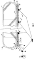
- Figure 1 shows a schematic side view of a people conveyor 1, in particular an escalator 1a, comprising an endless tread band 12 comprising a plurality of treads 13 (steps 13a) extending in a longitudinal conveyance direction between two landings 20, 21.
- the treads 13 comprise rollers 23 which are guided and supported by guide rails (not shown).
- the upper turnaround portion 17 is a driving portion and comprises a drive shaft 29 driven by a drive system 25 having a motor.
- the drive shaft 29 is driven by the drive system 25 via a transmission element 26, particularly a toothed belt, a belt or a chain.
- the drive shaft 29 supports a drive wheel 32.
- the drive control unit 42 is in communication with the drive system 25.
- the drive control unit 42 is configured to control the drive system 25.
- the endless tread band 12 passes from a conveyance portion 16 into a return portion 18, and vice versa.
- the lower turnaround portion 24 comprises a non-driven turnaround element 30, e.g. an idler wheel or an idler sprocket.
- the upper turnaround portion 17 comprises the drive wheel 32 as a turnaround element, around which the endless tread band 12 passes.
- the drive wheel 32 e.g. a sprocket or toothed wheel, is driven by the drive system 25.
- the lower turnaround portion 24 may be a driving portion.
- treads 13 For clarity, only some of the treads 13, in particular treads 13 traveling in the conveyance portion 16, are depicted in Figure 1 . Further, not all treads 13 and rollers 23 are denoted with reference signs.
- a tread drive tension member 15, particularly a drive chain, a drive belt or a toothed belt, extending along a closed loop is connected to the treads 13 (steps 13a).
- the tread drive tension member 15 is in engagement with and driven by the drive wheel 32 arranged in the upper turnaround portion 17.
- the people conveyor 1 further comprises a brake 31 which is configured for braking movement of the endless tread band 12.
- the brake 31 is depicted separately from the drive system 25 in Figure 1 .
- the brake 31, however, may be integrated with the drive system 25.
- the brake 31 may engage with the drive wheel 32 or the drive shaft 29.
- Balustrades 4 supporting moving handrails 6 extend parallel to the conveyance portion 16. Only one of the balustrades 4 is visible in the side view shown in Figure 1 .
- Figure 2 depicts a schematic side view of a people conveyor 1, which is provided as a moving walkway 1b.
- the moving walkway 1b comprises an endless tread band 12 of treads 13 (pallets 13b) moving in a longitudinal conveyance direction in an upper conveyance portion 16 and moving in a return direction opposite to the conveyance direction in a lower return portion 18.
- Landings 20, 21 are provided at both ends of the moving walkway 1b.
- a left turnaround portion 17 is provided at the landing 21, and a right turnaround portion 24 is provided at the landing 20.
- a turnaround element 30, in particular an idler wheel or an idler sprocket, is provided at the right turnaround portion 24.
- a drive wheel 32 forming a turnaround element is provided at the left turnaround portion 17.
- the endless tread band 12 passes from the conveyance portion 16 into the return portion 18 in the left turnaround portion 17 and in the right turnaround portion 24, and vice versa.
- the left turnaround portion 17 is a driving portion and comprises a drive shaft 29 driven by a drive system 25 via a transmission element 26, particularly a toothed belt, a belt or a chain.
- the drive system 25 comprises a motor.
- the drive shaft 29 supports the drive wheel 32.
- treads 13 are provided with reference signs.
- a tread drive tension member 15, particularly a drive chain, a drive belt or a toothed belt, extending along a closed loop is connected to the treads 13 (pallets 13b).
- the tread drive tension member 15 is in engagement with and driven by the drive wheel 32 (e.g. a sheave or a sprocket) arranged in the left turnaround portion 17.
- the moving walkway 1b further comprises a brake 31 which is configured for braking movement of the endless tread band 12.
- the brake 31 is depicted separately from the drive system 25 in Figure 2 .
- the brake 31, however, may be integrated with the drive system 25.
- the brake 31 may engage with the drive wheel 32 or the drive shaft 29.
- Balustrades 4 supporting moving handrails 6 extend parallel to the conveyance portion 16 on both lateral sides of the chain 12 of conveyance elements 13. Only one of the balustrades 4 is visible in the side view depicted in Figure 2 .
- Figures 1 and 2 also show a maintenance control system 40 comprising a remote control unit 44.
- the remote control unit 44 is in wireless communication with the drive control unit 42 of the people conveyor 1.
- the drive control unit 42 controls movement of the drive system 25.
- the drive control unit 42 provides commands for the drive motor to drive the tread band 12 in a clockwise rotation or counterclockwise rotation, and thereby controls the moving direction of the treads in the conveyance portion.
- the remote control unit 44 may be used to provide control signals to the drive control unit 42 for driving the drive system 25.
- the people conveyor 1 comprises a safety control circuit 46.
- the safety control circuit 46 comprises a plurality of safety switches 48 placed at different portions in the people conveyor 1, in particular in the drive system 25, in the return portion 18, in the conveyance portion 16, and at the landings 20, 21. Not all safety switches locations are depicted in the Figures.
- the safety control circuit 46 is in communication with the drive control unit 42.
- the safety control circuit 46 may comprise a safety chain formed by the safety switches 48.
- the safety chain may include further safety switches, for example safety relays 47 or 64, which are not depicted in Figures 1 and 2 . Operation of the people conveyor 1, particularly for driving the tread band 12, is only possible when the safety chain is closed.
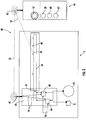
- Figure 3 shows a diagrammatic view of the maintenance control system 40 with the remote control unit 44 and its interaction with the people conveyor 1 comprising the drive control unit 42.
- the remote control unit 44 may be an inspection hand held unit.
- the remote control unit 44 comprises a transmitter/receiver 45 to transmit and receive control signals 56, in particular maintenance control signals, wirelessly to the drive control unit 42 and/or to the safety control circuit 46.
- the drive control unit 42 comprises a transmitter/receiver 43 to enable communication between the remote control unit 44 and the drive control unit 42 and/or the safety control circuit 46.
- the transmitter/receiver 43 may be positioned in the balustrade 4 or at one of the landings 20, 21 to provide optimal transmission power between the transmitter/receiver 43 of the drive control unit 42 and the transmitter/receiver 45 of the remote control unit 44.
- At least one of the safety switches 48 of the safety control circuit 46 may be configured to wirelessly communicate with the remote control unit 44.
- the remote control unit 44 allows wireless communication between the remote control unit 44 and the drive control unit 42 and/or the safety control circuit 46, no communication cables to connect the drive control unit 42 and/or the safety control circuit 46 with the remote control unit 44 are necessary. This eliminates the risk that communication cables are damaged by the tread band 12 when operating the people conveyor 1 during maintenance operation.
- the drive control unit 42 is in communication with the drive system 25, the brake 31, the safety control circuit 46 and the remote control unit 44.
- the drive control unit 42 receives movement direction signals 54 during normal operation (passenger operation), or receives maintenance control signals 56 via the remote control unit 44 during maintenance operation.
- the safety switch 47 may be a safety relay 47.
- the safety relay 47 may be included in, or connected with, the drive control unit 42.
- at least one of the safety switches in the safety control circuit 46 may be configured to communicate wirelessly with the remote control unit 44, as indicated by 49 in Fig.3 .
- the safety switch 49 may provide the functionality of the safety relay 47.
- the safety control circuit 46 is connected with a separate safety control unit 50.
- the safety control unit 50 includes a safety relay 64 and also a transmitter/receiver 51 for wirelessly communicating with the remote control unit 44.
- the remote control unit 44 can communicate with the drive control unit 42 and/or the safety control circuit 46 via the transmitter/receiver 51 and thus no separate transmitter/receiver is required for the drive control unit 42.
- the wireless communication may be achieved by a safety radio transmission 52, in particular by a bi-directional safety radio transmission.
- the remote control unit 44 comprises an emergency key 57 and a plurality of maintenance operation keys, particularly a first key 58 (upward movement), a second key 60 (downward movement), and a third key 62 (run key).
- the remote control unit 44 transmits a control signal to the safety switch 47 (or 49, or 64).
- the safety switch 47 or 49, or 64
- the safety switch 47 will open such that the safety control circuit 46 is interrupted. This triggers the drive control unit 42 to immediately stop movement of the drive system 25 thereby stopping the tread band 12 (not shown in Figure 3 ).
- at least one brake 31 will be activated.
- the first key 58 provides a control signal for moving the tread band 12 of the people conveyor 1 in an up or first direction 66.
- the second key 60 provides a control signal for moving the tread band 12 of the people conveyor 1 in a down direction 68 or opposite direction of the first direction 66.
- the control signals of either key 58 or 60 is only communicated to the drive control unit 42 when the third key 62 is activated or pressed simultaneously with either the first key 58 or the second key 60.
- the keys 58, 60 and 62 may be arranged so that two hands are needed for simultaneous operation of the first key 58 and the third key 62, or the second key 60 and the third key 62. This suppresses the likelihood of unintended operation by a maintenance person, since the maintenance person has to use both hands to activate movement of the tread band 12 of the people conveyor 1. This provides a two hand control configuration.
- Figure 4 shows a diagrammatic view of the people conveyor 1 comprising the drive control unit 42 and the maintenance control system 40 together with the remote control unit 44 according to a further embodiment.
- the maintenance control system 40 of Figure 4 further comprises the safety control unit 50 in wireless communication with the remote control unit 44 via the safety radio transmission 52.
- the safety control unit 50 comprises a transmitter/receiver 51 to enable wireless communication of the maintenance control signals 56 with the remote control unit 44.
- the safety control unit 50 is configured to communicate the maintenance control signals 56 to the drive control unit 42.
- the transmitter/receiver 51 may be positioned in the balustrade 4 or at one of the landing portions 20, 21 to provide optimal transmission power between the transmitter/receiver 51 of the safety control unit 50 and the transmitter/receiver 45 of the remote control unit 44.
- the drive control unit 42 is in communication with the drive system 25, the brake 31, the safety control circuit 46, and the safety control unit 50.
- the drive control unit 42 receives maintenance control signals 56 from the remote control unit 44 via the safety control unit 50 during maintenance operation.
- the movement direction signals 54 and the maintenance control signals 56 trigger movement of the tread band 12 of the people conveyor 1 in the first moving direction 66 or in the second moving direction 68, by communicating these signals to the drive system 25 to rotate in a clockwise or counterclockwise direction.
- the second moving direction 68 is opposite to the first moving direction 66.
- these control signals 54, 56 provide information to the brake 31 to brake the tread band 12 or to release the tread band 12 (not shown in Figure 4 ).
- the drive control unit 42 provides movement direction signals 54 or maintenance control signals 56 to the drive system 25 and the brake 31 as long as the plurality of safety switches 48, 64 of the safety control circuit 46 are closed. If one of the plurality of safety switches 48, 64 is open, the drive control unit 42 stops providing any movement direction signals 54 or maintenance control signals 56 to the drive system 25.
- the remote control unit 44 transmits a control signal to the safety control unit 50, which opens the safety switch 64 (particularly, the safety switch 64 may be a safety relay) such that the safety control circuit 46 is open.
- the safety switch 64 is integrated in the safety control unit 50. In another embodiment, the safety switch 64 may be positioned away from the safety control unit 50 in the safety control circuit 46.
- the first key 58, the second key 60 and the third key 62 provide identical control signals to the drive control unit 42 in Figures 3 and 4 .
Landscapes
- Escalators And Moving Walkways (AREA)
Abstract
Maintenance control system (40) for a people conveyor (1) of the type having a tread band (12) operable to transport passengers between landings (20, 21), the people conveyor (1) comprising a drive control unit (42) for controlling operation of the tread band (12), and a safety control circuit (46) including a plurality of safety switches (47, 48, 64), the maintenance control system (40) comprising a remote control unit (44). The remote control unit (44) comprises at least one maintenance operation key (58, 60, 62) configured to manually control operation of the tread band (12) by operating the at least one maintenance operation key (58, 60, 62), an emergency key (57) configured to provide an emergency stop signal, and a transmitter/receiver (45) configured to wirelessly communicate control signals between the remote control unit (44) and the drive control unit (42). The remote control unit (44) is configured to wirelessly communicate with the safety control circuit (46) of the people conveyor (1) to stop operation of the tread band (12), irrespective of the state of the at least one maintenance operation key (58, 60, 62), depending on the state of any of the safety switches (47, 48, 64) in the safety control circuit (46).
Description
- The invention relates to a maintenance control system for a people conveyor. The invention further relates to a people conveyor comprising a maintenance control system. Moreover, the invention relates to a method of using a maintenance control system.
- Several types of people conveyors, such as escalators, moving walkways, moving sidewalks, etc. are widely used to effectively transport passengers from one location to another. Areas of usage of these people conveyors often include airports, hotels, shopping malls, museums, railway stations and other public buildings. Such people conveyors typically have two landings (e.g., a top landing and a bottom landing in case of an escalator) and a plurality of treads, such as steps or pallets, interconnected to form an endless tread band. The treads travel within a conveyance section of the endless tread band in between the landings.
- These people conveyors are subject to maintenance operations. During maintenance operations an inspector controls operation of the people conveyor via a maintenance control system comprising a handheld operation control unit that is connected to the people conveyor by a cable. People conveyors comprise an inspection outlet in which the cable is inserted to transfer control signals from the handheld operation control unit to the people conveyor. These cables are becoming longer and heavier the longer the people conveyor is. Also, the risk increases that these cables are damaged. Moreover, people conveyors not only comprise one inspection outlet but a plurality of inspection outlets along the length of the people conveyor. These inspection outlets must be incorporated in a safety control circuit. Because of the large distances, relatively thick wires in the safety control circuit are required to avoid problems relating to correct operation voltage.
- It would be beneficial to improve the maintenance control system to enable an inspector to move freely around the people conveyor while performing maintenance and inspection operation of the people conveyor.
- An exemplary embodiment of the invention relates to a maintenance control system for a people conveyor having a tread band operable for transporting passengers between landings. The people conveyor comprises a drive control unit for controlling operation of the tread band, and a safety control circuit including a plurality of safety switches. The maintenance control system comprises a remote control unit. The remote control unit comprises at least one maintenance operation key configured to manually control operation of the tread band by operating the at least one maintenance operation key, an emergency key configured to provide an emergency stop signal, and a transmitter/receiver configured to wirelessly communicate control signals between the remote control unit and the drive control unit. The remote control unit is configured to wirelessly communicate with the safety control circuit of the people conveyor to stop operation of the tread band, irrespective of the state of the at least one maintenance operation key, depending on the state of any of the plurality of safety switches in the safety control circuit.
- The maintenance control system according to the exemplary embodiment allows improving the safety when operating a people conveyor during inspection and maintenance. It is normally required to manually control operation of the tread band when carrying out inspection or maintenance operations. In the embodiments described herein, maintenance operations can be carried out by operating the remote control unit and hence no cable can be pulled into moving elements of the people conveyor. Moreover, floor plates of a landing zone can be kept closed during inspection runs, since no cable has to be connected to the drive control unit of the people conveyor. Particularly, it is not required to extend wire connections to remote electrical outlets.
- A number of optional features are set out in the following. These features may be realized in particular embodiments, alone or in combination with any of the other features.
- The wireless communication between the remote control circuit and the power control unit, and/or the remote control unit and the safety circuit may be a wireless safety communication. The wireless safety communication, in particular may fulfil the safety requirements of people conveyor safety codes with respect to communication between switches in a safety control circuit.
- At least one of the plurality of safety switches may be a safety relay. The safety relay may be configured to wirelessly communicate with the remote control unit, particularly with the emergency key.
- The control signals communicated between the remote control unit and the drive control unit may be maintenance control signals. These maintenance control signals are used during maintenance operation, when an inspector inspects functionality of the people conveyor. The maintenance control signals may include manual operation of the tread band.
- The maintenance control system may further comprise a safety control unit connected in the safety control circuit. The safety control unit may have a transmitter/receiver configured to wirelessly communicate with the remote control unit, in particular via a wireless safety communication protocol. This allows a preferred communication between the safety control circuit and the remote control circuit.
- The safety control unit may be configured to communicate control signals from the remote control unit to the drive control unit. Thereby, manual operation commands may be input to the drive control unit via the remote control unit.
- The safety control unit may comprise a safety switch connected to the safety control circuit. The safety switch of the safety control unit may be directly controlled by the remote control unit.
- The at least one maintenance operation key may be configured to provide a control signal for manually operating the tread band of the people conveyor. This allows an inspector to provide control signals, in particular movement in clockwise direction or counterclockwise direction, to the drive system to move the tread band of the people conveyor in an up direction or in a down direction. In a moving walkway the moving directions may be from left to right or from right to left.
- The at least one maintenance operation key comprises a plurality of operation keys, particularly a first key configured to provide a control signal for commanding a first moving direction of the tread band of the people conveyor, a second key configured to provide a control signal for commanding a second moving direction opposite to the first moving direction, and a third key configured to provide a control signal for enabling the drive control unit to operate the tread band in the commanded first or second direction, when operated simultaneously with the first key or the second key. Such configuration improves the safety of the maintenance control system, since more than one key has to be pressed to activate movement of the tread band of the people conveyor.
- The first key, the second key, and the third key may be positioned such that two hands of a maintenance person are needed for simultaneous operation of either the first key and the third key, or the second key and the third key. This increases the safety for the maintenance person, since both hands hold the remote control unit to provide manual operation of the tread band.
- The remote control unit is equipped with an emergency key connceted with the safety control circuit in a wireless manner. The emergency key may be configured to provide the emergency stop signal when operated by an operator of the remote control unit. The emergency stop signal may be given high priority so that it is communicated to the safety control circuit. Such configuration is particularly safe, since only one key has to be operated, activated or pressed to stop movement of the people conveyor.
- The remote control unit may be an inspection handheld unit, which is carried by a maintenance person or technician while performing inspection and/or maintenance operations at the people conveyor.
- The remote control unit may be configured to communicate via a safety radio transmission. In particular, the safety radio transmission may be a bi-directional safety radio transmission. This allows to safely communicate control signals back and forth between the remote control unit and the drive control unit and/or the safety control circuit.
- The maintenance control system may be configured to detect presence of the remote control unit within a communication region around the drive control unit and/or the safety control circuit, and to switch the maintenance control system into an active mode, when the remote control unit is detected. This increases the safety during maintenance work and the reliability of the maintenance control system. To avoid unintended activation, it may be required to input an activation code via the remote control unit before the remote control unit is available for manual operation of the tread band.
- The remote control unit may be configured to send an activation signal to the drive control unit and/or the safety control circuit. The activation signal may be sent upon operation of the remote control unit, e.g. by input of an activation code. Alternatively, the activation signal could be sent automatically, for example when the drive control unit or the safety control circuit receives an identification signal from the remote control unit, it may be configured to carry out an authentification procedure. Upon reception of the authentication, the remote control unit may be activated.
- A people conveyor according to an exemplary embodiment of the invention has a tread band operable to transport passengers between landings. The people conveyor further comprises a drive system to drive the tread band, a drive control unit to control the drive system, a safety control circuit comprising a plurality of safety switches, and a maintenance control system according to an exemplary embodiment of the invention.
- The people conveyor may comprise a brake unit to brake or stop the tread band when moving. The brake may be integrated in the drive system or may be positioned separately in the people conveyor. Often, two or more redundant brake systems will be provided.
- The control signals may be drive control signals that are configured to drive the motor, to actuate the brake, or to interrupt the safety control circuit to initiate an emergency stop. This allows safe control of the people conveyor.
- The drive control unit may be configured to control a movement direction of the tread band of the people conveyor.
- The people conveyor may be an escalator comprising a plurality of steps forming the tread band, or a moving walkway comprising a plurality of pallets forming the tread band.
- Another exemplary embodiment of the invention is a method of carrying out a maintenance operation in a people conveyor. The method comprises the step of operating the people conveyor using the maintenance control system according to an exemplary embodiment of the invention.
- In the following exemplary embodiments of the invention are described with reference to the enclosed figures.
-
Figure 1 depicts a schematic side view of a an escalator. -
Figure 2 depicts a schematic side view of a moving walkway. -
Figure 3 shows a schematic diagram of a people conveyor comprising a maintenance control system according to a first embodiment. -
Figure 4 depicts a schematic diagram of a people conveyor comprising a maintenance control system according to a second embodiment. -
Figure 1 shows a schematic side view of apeople conveyor 1, in particular an escalator 1a, comprising anendless tread band 12 comprising a plurality of treads 13 (steps 13a) extending in a longitudinal conveyance direction between twolandings rollers 23 which are guided and supported by guide rails (not shown). - An
upper turnaround portion 17 is provided next to thelanding 20. Theupper turnaround portion 17 is a driving portion and comprises adrive shaft 29 driven by adrive system 25 having a motor. Thedrive shaft 29 is driven by thedrive system 25 via atransmission element 26, particularly a toothed belt, a belt or a chain. Thedrive shaft 29 supports adrive wheel 32. Thedrive control unit 42 is in communication with thedrive system 25. Thedrive control unit 42 is configured to control thedrive system 25. - In the
upper turnaround portion 17 next to thelanding 20 and in thelower turnaround portion 24 next to the landing 21 theendless tread band 12 passes from aconveyance portion 16 into areturn portion 18, and vice versa. Thelower turnaround portion 24 comprises anon-driven turnaround element 30, e.g. an idler wheel or an idler sprocket. Theupper turnaround portion 17 comprises thedrive wheel 32 as a turnaround element, around which theendless tread band 12 passes. Thedrive wheel 32, e.g. a sprocket or toothed wheel, is driven by thedrive system 25. - Alternatively, the
lower turnaround portion 24 may be a driving portion. - For clarity, only some of the treads 13, in particular treads 13 traveling in the
conveyance portion 16, are depicted inFigure 1 . Further, not all treads 13 androllers 23 are denoted with reference signs. - A tread
drive tension member 15, particularly a drive chain, a drive belt or a toothed belt, extending along a closed loop is connected to the treads 13 (steps 13a). The treaddrive tension member 15 is in engagement with and driven by thedrive wheel 32 arranged in theupper turnaround portion 17. - The
people conveyor 1 further comprises abrake 31 which is configured for braking movement of theendless tread band 12. Thebrake 31 is depicted separately from thedrive system 25 inFigure 1 . Thebrake 31, however, may be integrated with thedrive system 25. For example, thebrake 31 may engage with thedrive wheel 32 or thedrive shaft 29. -
Balustrades 4 supporting movinghandrails 6 extend parallel to theconveyance portion 16. Only one of thebalustrades 4 is visible in the side view shown inFigure 1 . -
Figure 2 depicts a schematic side view of apeople conveyor 1, which is provided as a moving walkway 1b. - The moving walkway 1b comprises an
endless tread band 12 of treads 13 (pallets 13b) moving in a longitudinal conveyance direction in anupper conveyance portion 16 and moving in a return direction opposite to the conveyance direction in alower return portion 18. -
Landings left turnaround portion 17 is provided at thelanding 21, and aright turnaround portion 24 is provided at thelanding 20. Aturnaround element 30, in particular an idler wheel or an idler sprocket, is provided at theright turnaround portion 24. Adrive wheel 32 forming a turnaround element is provided at theleft turnaround portion 17. Theendless tread band 12 passes from theconveyance portion 16 into thereturn portion 18 in theleft turnaround portion 17 and in theright turnaround portion 24, and vice versa. - The
left turnaround portion 17 is a driving portion and comprises adrive shaft 29 driven by adrive system 25 via atransmission element 26, particularly a toothed belt, a belt or a chain. Thedrive system 25 comprises a motor. Thedrive shaft 29 supports thedrive wheel 32. - For clarity not all treads 13 (pallets 13b) are provided with reference signs.
- A tread
drive tension member 15, particularly a drive chain, a drive belt or a toothed belt, extending along a closed loop is connected to the treads 13 (pallets 13b). The treaddrive tension member 15 is in engagement with and driven by the drive wheel 32 (e.g. a sheave or a sprocket) arranged in theleft turnaround portion 17. - The moving walkway 1b further comprises a
brake 31 which is configured for braking movement of theendless tread band 12. Thebrake 31 is depicted separately from thedrive system 25 inFigure 2 . Thebrake 31, however, may be integrated with thedrive system 25. For example, thebrake 31 may engage with thedrive wheel 32 or thedrive shaft 29. -
Balustrades 4 supporting movinghandrails 6 extend parallel to theconveyance portion 16 on both lateral sides of thechain 12 of conveyance elements 13. Only one of thebalustrades 4 is visible in the side view depicted inFigure 2 . -
Figures 1 and2 also show amaintenance control system 40 comprising aremote control unit 44. Theremote control unit 44 is in wireless communication with thedrive control unit 42 of thepeople conveyor 1. Thedrive control unit 42 controls movement of thedrive system 25. In particular, thedrive control unit 42 provides commands for the drive motor to drive thetread band 12 in a clockwise rotation or counterclockwise rotation, and thereby controls the moving direction of the treads in the conveyance portion. Theremote control unit 44 may be used to provide control signals to thedrive control unit 42 for driving thedrive system 25. - The
people conveyor 1 comprises asafety control circuit 46. Thesafety control circuit 46 comprises a plurality ofsafety switches 48 placed at different portions in thepeople conveyor 1, in particular in thedrive system 25, in thereturn portion 18, in theconveyance portion 16, and at thelandings safety control circuit 46 is in communication with thedrive control unit 42. Particularly, thesafety control circuit 46 may comprise a safety chain formed by the safety switches 48. The safety chain may include further safety switches, for example safety relays 47 or 64, which are not depicted inFigures 1 and2 . Operation of thepeople conveyor 1, particularly for driving thetread band 12, is only possible when the safety chain is closed. - When one of the plurality of
safety switches 48 is in an open position, thepeople conveyor 1 is stopped immediately and thepeople conveyor 1 cannot be activated until therespective safety switch 48 is brought into a closed position. -
Figure 3 shows a diagrammatic view of themaintenance control system 40 with theremote control unit 44 and its interaction with thepeople conveyor 1 comprising thedrive control unit 42. Theremote control unit 44 may be an inspection hand held unit. Theremote control unit 44 comprises a transmitter/receiver 45 to transmit and receivecontrol signals 56, in particular maintenance control signals, wirelessly to thedrive control unit 42 and/or to thesafety control circuit 46. Thedrive control unit 42 comprises a transmitter/receiver 43 to enable communication between theremote control unit 44 and thedrive control unit 42 and/or thesafety control circuit 46. - The transmitter/
receiver 43 may be positioned in thebalustrade 4 or at one of thelandings receiver 43 of thedrive control unit 42 and the transmitter/receiver 45 of theremote control unit 44. - In some embodiments, at least one of the safety switches 48 of the
safety control circuit 46 may be configured to wirelessly communicate with theremote control unit 44. - Since the
remote control unit 44 allows wireless communication between theremote control unit 44 and thedrive control unit 42 and/or thesafety control circuit 46, no communication cables to connect thedrive control unit 42 and/or thesafety control circuit 46 with theremote control unit 44 are necessary. This eliminates the risk that communication cables are damaged by thetread band 12 when operating thepeople conveyor 1 during maintenance operation. - The
drive control unit 42 is in communication with thedrive system 25, thebrake 31, thesafety control circuit 46 and theremote control unit 44. Thedrive control unit 42 receives movement direction signals 54 during normal operation (passenger operation), or receives maintenance control signals 56 via theremote control unit 44 during maintenance operation. - The
safety switch 47 may be asafety relay 47. Thesafety relay 47 may be included in, or connected with, thedrive control unit 42. Alternatively, or in addition, at least one of the safety switches in thesafety control circuit 46 may be configured to communicate wirelessly with theremote control unit 44, as indicated by 49 inFig.3 . In this case, thesafety switch 49 may provide the functionality of thesafety relay 47. - A further possibility is shown in
Fig. 4 . Here, thesafety control circuit 46 is connected with a separatesafety control unit 50. Thesafety control unit 50 includes asafety relay 64 and also a transmitter/receiver 51 for wirelessly communicating with theremote control unit 44. In this case, theremote control unit 44 can communicate with thedrive control unit 42 and/or thesafety control circuit 46 via the transmitter/receiver 51 and thus no separate transmitter/receiver is required for thedrive control unit 42. The wireless communication may be achieved by asafety radio transmission 52, in particular by a bi-directional safety radio transmission. - The
remote control unit 44 comprises anemergency key 57 and a plurality of maintenance operation keys, particularly a first key 58 (upward movement), a second key 60 (downward movement), and a third key 62 (run key). - When the
emergency key 57 is operated, activated or pressed, theremote control unit 44 transmits a control signal to the safety switch 47 (or 49, or 64). In reaction to receipt of this control signal, the safety switch 47 (or 49, or 64) will open such that thesafety control circuit 46 is interrupted. This triggers thedrive control unit 42 to immediately stop movement of thedrive system 25 thereby stopping the tread band 12 (not shown inFigure 3 ). In addition, at least onebrake 31 will be activated. - The first key 58 provides a control signal for moving the
tread band 12 of thepeople conveyor 1 in an up orfirst direction 66. The second key 60 provides a control signal for moving thetread band 12 of thepeople conveyor 1 in adown direction 68 or opposite direction of thefirst direction 66. The control signals of either key 58 or 60 is only communicated to thedrive control unit 42 when the third key 62 is activated or pressed simultaneously with either the first key 58 or thesecond key 60. - The
keys third key 62. This suppresses the likelihood of unintended operation by a maintenance person, since the maintenance person has to use both hands to activate movement of thetread band 12 of thepeople conveyor 1. This provides a two hand control configuration. -
Figure 4 shows a diagrammatic view of thepeople conveyor 1 comprising thedrive control unit 42 and themaintenance control system 40 together with theremote control unit 44 according to a further embodiment. As mentioned above, themaintenance control system 40 ofFigure 4 further comprises thesafety control unit 50 in wireless communication with theremote control unit 44 via thesafety radio transmission 52. Thesafety control unit 50 comprises a transmitter/receiver 51 to enable wireless communication of the maintenance control signals 56 with theremote control unit 44. - The
safety control unit 50 is configured to communicate the maintenance control signals 56 to thedrive control unit 42. - The transmitter/
receiver 51 may be positioned in thebalustrade 4 or at one of thelanding portions receiver 51 of thesafety control unit 50 and the transmitter/receiver 45 of theremote control unit 44. - The
drive control unit 42 is in communication with thedrive system 25, thebrake 31, thesafety control circuit 46, and thesafety control unit 50. Thedrive control unit 42 receives maintenance control signals 56 from theremote control unit 44 via thesafety control unit 50 during maintenance operation. - In the same way as described above with reference to
Figure 3 , the movement direction signals 54 and the maintenance control signals 56 trigger movement of thetread band 12 of thepeople conveyor 1 in the first movingdirection 66 or in the second movingdirection 68, by communicating these signals to thedrive system 25 to rotate in a clockwise or counterclockwise direction. The second movingdirection 68 is opposite to the first movingdirection 66. Moreover, these control signals 54, 56 provide information to thebrake 31 to brake thetread band 12 or to release the tread band 12 (not shown inFigure 4 ). - The
drive control unit 42 provides movement direction signals 54 or maintenance control signals 56 to thedrive system 25 and thebrake 31 as long as the plurality ofsafety switches safety control circuit 46 are closed. If one of the plurality ofsafety switches drive control unit 42 stops providing any movement direction signals 54 or maintenance control signals 56 to thedrive system 25. - When the
emergency key 57 is operated, activated or pressed, theremote control unit 44 transmits a control signal to thesafety control unit 50, which opens the safety switch 64 (particularly, thesafety switch 64 may be a safety relay) such that thesafety control circuit 46 is open. This results in thedrive control unit 42 to immediately stop movement of thedrive system 25 thereby stopping the tread band 12 (not shown inFigure 3 ). Thesafety switch 64 is integrated in thesafety control unit 50. In another embodiment, thesafety switch 64 may be positioned away from thesafety control unit 50 in thesafety control circuit 46. - The first key 58, the second key 60 and the third key 62 provide identical control signals to the
drive control unit 42 inFigures 3 and4 . - While the invention has been described with reference to exemplary embodiments, it will be understood by those skilled in the art that various changes may be made and equivalents may be substituted for elements thereof without departing from the scope of the invention. In addition, many modifications may be made to adopt a particular situation or material to the teachings of the invention without departing from the essential scope thereof. Therefore, it is intended that the invention is not limited to the particular embodiments disclosed, but that the invention includes all embodiments falling within the scope of the claims.
-
- 1
- people conveyor
- 1a
- escalator
- 1b
- moving walkway
- 4
- balustrade
- 6
- moving handrail
- 12
- tread band
- 13
- treads
- 13a
- steps
- 13b
- pallets
- 15
- tread drive tension member
- 16
- conveyance portion
- 17
- upper/left turnaround portion
- 18
- return portion
- 20, 21
- landings
- 23
- rollers
- 24
- (lower/right) turnaround portion
- 25
- drive system
- 26
- transmission element
- 29
- drive shaft
- 30
- turnaround element
- 31
- brake
- 32
- drive wheel (sheave or sprocket)
- 40
- maintenance control system
- 42
- drive control unit
- 43
- transmitter/receiver of the drive control unit
- 44
- remote control unit
- 45
- transmitter/receiver of the remote control unit
- 46
- safety control circuit
- 47
- safety switch, in particular a safety relay
- 48
- safety switch
- 49
- safety switch
- 50
- safety control unit
- 51
- transmitter/receiver of the safety control unit
- 52
- safety radio transmission
- 54
- movement direction signals
- 56
- maintenance control signals
- 57
- emergency key
- 58
- first key
- 60
- second key
- 62
- third key
- 64
- safety switch, in particular a safety relay
- 66
- first moving direction
- 68
- second moving direction
Claims (15)
- Maintenance control system (40) for a people conveyor (1) having a tread band (12) operable for transporting passengers between landings (20, 21), the people conveyor (1) comprising a drive control unit (42) for controlling operation of the tread band (12), and a safety control circuit (46) including a plurality of safety switches (47, 48, 49, 64), the maintenance control system (40) comprising:a remote control unit (44) comprisingat least one maintenance operation key (58, 60, 62) configured to manually control operation of the tread band (12) by operating the at least one maintenance operation key (58, 60, 62);an emergency key (57) configured to provide an emergency stop signal; anda transmitter/receiver (45) configured to wirelessly communicate control signals between the remote control unit (44) and the drive control unit (42);wherein the remote control unit (44) is configured to wirelessly communicate with the safety control circuit (46) of the people conveyor (1) to stop operation of the tread band (12), irrespective of the state of the at least one maintenance operation key (58, 60, 62), depending on the state of any of the safety switches (47, 48, 49, 64) in the safety control circuit (46).
- Maintenance control system (40) according to claim 1, wherein the safety control circuit (46) comprises a safety control unit (50), the safety control unit (50) having a transmitter/receiver (51) configured to wirelessly communicate with the remote control unit (44).
- Maintenance control system (40) according to claim 2, wherein the safety control unit (50) is configured to communicate control signals from the remote control unit (44) to the drive control unit (42).
- Maintenance control system (40) according to claim 2 or 3, wherein the safety control unit (50) comprises a safety switch (64) connected to the safety control circuit (46).
- Maintenance control system (40) according to any of the previous claims, wherein the at least one maintenance operation key (58, 60, 62) is configured for providing a control signal for manually operating the tread band (12) of the people conveyor (1).
- Maintenance control system (40) according to claim 5, wherein the at least one of maintenance operation key (58, 60, 62) comprises a plurality of operation keys (58, 60, 62), particularly:a first key (58) configured to provide a control signal for commanding a first moving direction of the tread band (12) of the people conveyor (1);a second key (60) configured to provide a control signal for commanding a second moving direction opposite to the first moving direction; anda third key (62) configured to provide a control signal for enabling the drive control unit (42) to operate the tread band (12) in the commanded first or second direction, when operated simultaneously with the first key (58) or the second key (60).
- Maintenance control system (40) according to claim 6, wherein the plurality of operation keys (58, 60, 62), particularly the first key (58), the second key (60), and the third key (62), are positioned such that two hands of a maintenance person are needed for simultaneous operation of the plurality of operation keys (58, 60, 62), particularly for simultaneous operation of either the first key (58) and the third key (62), or the second key (60) and the third key (62).
- Maintenance control system (40) according to any of the previous claims, wherein the emergency key (57) is configured to provide the emergency stop signal when operated, irrespective of additional operation of the at least one maintenance operation key (58, 60, 62).
- Maintenance control system (40) according to any of the previous claims, wherein the remote control unit (44) is an inspection handheld unit.
- Maintenance control system (40) according to any of the previous claims, wherein the remote control unit (44) is configured to communicate via a safety radio transmission (52), particularly a bi-directional safety radio transmission.
- Maintenance control system (40) according to any of the previous claims, wherein the safety control circuit (46) is configured to detect presence of a remote control unit (44) within a communication region around the drive control unit (42) and/or safety control circuit (46) and to switch the maintenance control system (40) into an active mode when the remote control unit (44) is detected.
- Maintenance control system (40) according to any of the previous claims, wherein the remote control unit (44) is configured to send an activation signal to the drive control unit (42) and/or the safety control circuit (46).
- People conveyor (1) having a tread band (12) operable to transport passengers between landings (20, 21), the people conveyor (1) comprising:a drive system (25) to drive the tread band (12);a drive control unit (42) to control the drive system (25);a safety control circuit (46) comprising a plurality of safety switches (47, 48, 64), andthe maintenance control system (40) according to any of the previous claims.
- People conveyor (1) according to claim 13, wherein the people conveyor (1) is an escalator (1a) comprising a plurality of steps (13a) forming the tread band (12); or wherein the people conveyor (1) is a moving walkway (1b) comprising a plurality of pallets (13b) forming the tread band (12).
- Method of carrying out a maintenance operation in a people conveyor (1), the method comprising:
operating the people conveyor (1) using the maintenance control system (40) according to any of claims 1 to 12.
Priority Applications (1)
| Application Number | Priority Date | Filing Date | Title |
|---|---|---|---|
| EP18171025.2A EP3566997A1 (en) | 2018-05-07 | 2018-05-07 | Maintenance control system, people conveyor with maintenance control system and method of using maintenance control system |
Applications Claiming Priority (1)
| Application Number | Priority Date | Filing Date | Title |
|---|---|---|---|
| EP18171025.2A EP3566997A1 (en) | 2018-05-07 | 2018-05-07 | Maintenance control system, people conveyor with maintenance control system and method of using maintenance control system |
Publications (1)
| Publication Number | Publication Date |
|---|---|
| EP3566997A1 true EP3566997A1 (en) | 2019-11-13 |
Family
ID=62134093
Family Applications (1)
| Application Number | Title | Priority Date | Filing Date |
|---|---|---|---|
| EP18171025.2A Withdrawn EP3566997A1 (en) | 2018-05-07 | 2018-05-07 | Maintenance control system, people conveyor with maintenance control system and method of using maintenance control system |
Country Status (1)
| Country | Link |
|---|---|
| EP (1) | EP3566997A1 (en) |
Cited By (3)
| Publication number | Priority date | Publication date | Assignee | Title |
|---|---|---|---|---|
| JP2021187660A (en) * | 2020-06-04 | 2021-12-13 | 三菱電機ビルテクノサービス株式会社 | Remote monitoring system of passenger conveyor |
| WO2022148896A1 (en) | 2021-01-08 | 2022-07-14 | Kone Corporation | Control of operation of a conveyor system |
| US20240253952A1 (en) * | 2023-01-30 | 2024-08-01 | Otis Elevator Company | A controlling system for safety, a controlling method for safety, a safety switch and an escalator system |
Citations (2)
| Publication number | Priority date | Publication date | Assignee | Title |
|---|---|---|---|---|
| JP2013107770A (en) * | 2011-11-24 | 2013-06-06 | Toshiba Elevator Co Ltd | Passenger conveyor |
| JP6117321B1 (en) * | 2015-11-20 | 2017-04-19 | 東芝エレベータ株式会社 | Passenger conveyor operating device and passenger conveyor using the same |
-
2018
- 2018-05-07 EP EP18171025.2A patent/EP3566997A1/en not_active Withdrawn
Patent Citations (2)
| Publication number | Priority date | Publication date | Assignee | Title |
|---|---|---|---|---|
| JP2013107770A (en) * | 2011-11-24 | 2013-06-06 | Toshiba Elevator Co Ltd | Passenger conveyor |
| JP6117321B1 (en) * | 2015-11-20 | 2017-04-19 | 東芝エレベータ株式会社 | Passenger conveyor operating device and passenger conveyor using the same |
Cited By (7)
| Publication number | Priority date | Publication date | Assignee | Title |
|---|---|---|---|---|
| JP2021187660A (en) * | 2020-06-04 | 2021-12-13 | 三菱電機ビルテクノサービス株式会社 | Remote monitoring system of passenger conveyor |
| WO2022148896A1 (en) | 2021-01-08 | 2022-07-14 | Kone Corporation | Control of operation of a conveyor system |
| CN116710385A (en) * | 2021-01-08 | 2023-09-05 | 通力股份公司 | Control of the operation of the conveyor system |
| EP4274795A4 (en) * | 2021-01-08 | 2024-01-24 | KONE Corporation | CONTROL OF THE OPERATION OF A TRANSPORT SYSTEM |
| US20240253952A1 (en) * | 2023-01-30 | 2024-08-01 | Otis Elevator Company | A controlling system for safety, a controlling method for safety, a safety switch and an escalator system |
| EP4431430A1 (en) * | 2023-01-30 | 2024-09-18 | Otis Elevator Company | Safety control system, safety control method, safety switch and escalator system |
| US12552643B2 (en) * | 2023-01-30 | 2026-02-17 | Otis Elevator Company | Controlling system for safety, a controlling method for safety, a safety switch and an escalator system |
Similar Documents
| Publication | Publication Date | Title |
|---|---|---|
| US4904916A (en) | Electrical control system for stairway wheelchair lift | |
| US9371210B2 (en) | Elevator safety system having multiple buses | |
| KR20090099563A (en) | Passenger Conveyor Handrail Drive Control Strategy | |
| CN110830941A (en) | Wireless data communication in a system | |
| EP1864934B1 (en) | Elevator apparatus | |
| JP6117321B1 (en) | Passenger conveyor operating device and passenger conveyor using the same | |
| JP6445652B1 (en) | Passenger conveyor | |
| JP5191801B2 (en) | Passenger conveyor | |
| CN107098254A (en) | The maintenance inspection system of passenger conveyors | |
| US20150217969A1 (en) | Security system for elevator | |
| KR101686710B1 (en) | Cooperating Passenger transport and escalators automatic operation system | |
| JP2007210710A (en) | Passenger conveyor | |
| JP2010058898A (en) | Operation control device for escalator | |
| CN100542935C (en) | Passenger conveying appliance | |
| JP2013129524A (en) | Safety device for passenger conveyor | |
| CN109941874B (en) | Monitoring interlocking system and method for multiple escalators | |
| CN211619732U (en) | Step monitoring device for passenger conveyor and passenger conveyor | |
| CN110920633B (en) | Ferry type rail transit boarding and disembarking system and running mode | |
| KR20100104230A (en) | Safety devide of escalator | |
| CN206033007U (en) | Intelligent handrail monitoring system and escalator and sidewalk comprising same | |
| JPH02123092A (en) | Safety device for passenger conveyer | |
| JPH0524780A (en) | Getting on-off port device for man conveyer | |
| JP6772303B2 (en) | Passenger conveyor | |
| KR20230089488A (en) | Escalator for wheelchairs and strollers and the method using the same | |
| CN120172232A (en) | Method for controlling a conveying device, control device, and conveying device |
Legal Events
| Date | Code | Title | Description |
|---|---|---|---|
| PUAI | Public reference made under article 153(3) epc to a published international application that has entered the european phase |
Free format text: ORIGINAL CODE: 0009012 |
|
| AK | Designated contracting states |
Kind code of ref document: A1 Designated state(s): AL AT BE BG CH CY CZ DE DK EE ES FI FR GB GR HR HU IE IS IT LI LT LU LV MC MK MT NL NO PL PT RO RS SE SI SK SM TR |
|
| AX | Request for extension of the european patent |
Extension state: BA ME |
|
| STAA | Information on the status of an ep patent application or granted ep patent |
Free format text: STATUS: THE APPLICATION IS DEEMED TO BE WITHDRAWN |
|
| 18D | Application deemed to be withdrawn |
Effective date: 20200603 |