EP3566942A1 - Automatic steering device, automatic steering method and automatic steering program - Google Patents
Automatic steering device, automatic steering method and automatic steering program Download PDFInfo
- Publication number
- EP3566942A1 EP3566942A1 EP19173505.9A EP19173505A EP3566942A1 EP 3566942 A1 EP3566942 A1 EP 3566942A1 EP 19173505 A EP19173505 A EP 19173505A EP 3566942 A1 EP3566942 A1 EP 3566942A1
- Authority
- EP
- European Patent Office
- Prior art keywords
- ship
- steering angle
- route
- intermediate waypoint
- command steering
- Prior art date
- Legal status (The legal status is an assumption and is not a legal conclusion. Google has not performed a legal analysis and makes no representation as to the accuracy of the status listed.)
- Pending
Links
- 238000000034 method Methods 0.000 title claims description 24
- 230000004044 response Effects 0.000 claims description 18
- 238000004364 calculation method Methods 0.000 claims description 11
- 238000012545 processing Methods 0.000 description 3
- 230000000052 comparative effect Effects 0.000 description 2
- 238000005259 measurement Methods 0.000 description 2
- NAWXUBYGYWOOIX-SFHVURJKSA-N (2s)-2-[[4-[2-(2,4-diaminoquinazolin-6-yl)ethyl]benzoyl]amino]-4-methylidenepentanedioic acid Chemical compound C1=CC2=NC(N)=NC(N)=C2C=C1CCC1=CC=C(C(=O)N[C@@H](CC(=C)C(O)=O)C(O)=O)C=C1 NAWXUBYGYWOOIX-SFHVURJKSA-N 0.000 description 1
- 241000083700 Ambystoma tigrinum virus Species 0.000 description 1
- 230000000694 effects Effects 0.000 description 1
- 238000005516 engineering process Methods 0.000 description 1
- 238000002474 experimental method Methods 0.000 description 1
- 239000000446 fuel Substances 0.000 description 1
- 238000012986 modification Methods 0.000 description 1
- 230000004048 modification Effects 0.000 description 1
- 238000004088 simulation Methods 0.000 description 1
- 230000002123 temporal effect Effects 0.000 description 1
- XLYOFNOQVPJJNP-UHFFFAOYSA-N water Substances O XLYOFNOQVPJJNP-UHFFFAOYSA-N 0.000 description 1
Images


Classifications
-
- B—PERFORMING OPERATIONS; TRANSPORTING
- B63—SHIPS OR OTHER WATERBORNE VESSELS; RELATED EQUIPMENT
- B63H—MARINE PROPULSION OR STEERING
- B63H21/00—Use of propulsion power plant or units on vessels
- B63H21/21—Control means for engine or transmission, specially adapted for use on marine vessels
-
- B—PERFORMING OPERATIONS; TRANSPORTING
- B63—SHIPS OR OTHER WATERBORNE VESSELS; RELATED EQUIPMENT
- B63H—MARINE PROPULSION OR STEERING
- B63H25/00—Steering; Slowing-down otherwise than by use of propulsive elements; Dynamic anchoring, i.e. positioning vessels by means of main or auxiliary propulsive elements
- B63H25/02—Initiating means for steering, for slowing down, otherwise than by use of propulsive elements, or for dynamic anchoring
- B63H25/04—Initiating means for steering, for slowing down, otherwise than by use of propulsive elements, or for dynamic anchoring automatic, e.g. reacting to compass
-
- B—PERFORMING OPERATIONS; TRANSPORTING
- B63—SHIPS OR OTHER WATERBORNE VESSELS; RELATED EQUIPMENT
- B63H—MARINE PROPULSION OR STEERING
- B63H25/00—Steering; Slowing-down otherwise than by use of propulsive elements; Dynamic anchoring, i.e. positioning vessels by means of main or auxiliary propulsive elements
- B63H25/06—Steering by rudders
- B63H25/36—Rudder-position indicators
-
- G—PHYSICS
- G01—MEASURING; TESTING
- G01C—MEASURING DISTANCES, LEVELS OR BEARINGS; SURVEYING; NAVIGATION; GYROSCOPIC INSTRUMENTS; PHOTOGRAMMETRY OR VIDEOGRAMMETRY
- G01C21/00—Navigation; Navigational instruments not provided for in groups G01C1/00 - G01C19/00
- G01C21/26—Navigation; Navigational instruments not provided for in groups G01C1/00 - G01C19/00 specially adapted for navigation in a road network
- G01C21/34—Route searching; Route guidance
- G01C21/3407—Route searching; Route guidance specially adapted for specific applications
-
- G—PHYSICS
- G05—CONTROLLING; REGULATING
- G05D—SYSTEMS FOR CONTROLLING OR REGULATING NON-ELECTRIC VARIABLES
- G05D1/00—Control of position, course or altitude of land, water, air, or space vehicles, e.g. automatic pilot
- G05D1/02—Control of position or course in two dimensions
- G05D1/0206—Control of position or course in two dimensions specially adapted to water vehicles
-
- B—PERFORMING OPERATIONS; TRANSPORTING
- B63—SHIPS OR OTHER WATERBORNE VESSELS; RELATED EQUIPMENT
- B63H—MARINE PROPULSION OR STEERING
- B63H21/00—Use of propulsion power plant or units on vessels
- B63H21/21—Control means for engine or transmission, specially adapted for use on marine vessels
- B63H2021/216—Control means for engine or transmission, specially adapted for use on marine vessels using electric control means
-
- B—PERFORMING OPERATIONS; TRANSPORTING
- B63—SHIPS OR OTHER WATERBORNE VESSELS; RELATED EQUIPMENT
- B63H—MARINE PROPULSION OR STEERING
- B63H25/00—Steering; Slowing-down otherwise than by use of propulsive elements; Dynamic anchoring, i.e. positioning vessels by means of main or auxiliary propulsive elements
- B63H25/02—Initiating means for steering, for slowing down, otherwise than by use of propulsive elements, or for dynamic anchoring
- B63H25/04—Initiating means for steering, for slowing down, otherwise than by use of propulsive elements, or for dynamic anchoring automatic, e.g. reacting to compass
- B63H2025/045—Initiating means for steering, for slowing down, otherwise than by use of propulsive elements, or for dynamic anchoring automatic, e.g. reacting to compass making use of satellite radio beacon positioning systems, e.g. the Global Positioning System [GPS]
Definitions
- the present disclosure relates to an automatic steering device, an automatic steering method, and an automatic steering program.
- JP1995-242199A discloses an automatic steering method which changes a route (veers) by turning at a constant turn rate ⁇ from a current route QX into a new or next route QY.
- the method calculates a veering point B on the current route QX based on a specified turning radius R or a turning radius R determined from the turn rate ⁇ and a ship speed V.
- the method then calculates a veering line LB passing through the veering point B and is parallel to the new route QY.
- the veering is started when a ship passes the veering line LB (also, refer to JP2005-178434A ).
- the ship may not be able to travel along the desired route due to external factors, such as waves.
- the present disclosure is made in view of solving the above problem, and one purpose thereof is to provide an automatic steering device, an automatic steering method, and an automatic steering program, capable of causing a ship to more accurately travel along a route to turn a ship.
- an automatic steering device may comprise a route calculator, an intermediate waypoint calculating module, a command steering angle calculating module, and a steering controlling module.
- the route calculator may calculate a route of a ship based on positions of a plurality of target points.
- the intermediate waypoint calculating module may calculate an intermediate waypoint ahead of the ship.
- the command steering angle calculating module may calculate a command steering angle based on a positional relation between the route and the intermediate waypoint.
- the steering controlling module may control a steering mechanism of the ship based on the command steering angle.
- the intermediate waypoint calculating module calculates the intermediate waypoint based on a response of the ship to the command steering angle.
- the intermediate waypoint calculating module calculates the intermediate waypoint based on a traveling speed of the ship.
- the intermediate waypoint calculating module calculates the intermediate waypoint based on a course setting of the ship and a current course of the ship.
- the command steering angle calculating module calculates the command steering angle based on a tangent direction at an intersection of a straight line passing through the center of a circle having the route as a part thereof and the intermediate waypoint, and the route.
- the command steering angle calculating module calculates the command steering angle further based on a distance between the intermediate waypoint and the intersection.
- the command steering angle calculating module calculates and updates the command steering angle periodically or irregularly.
- the command steering angle calculating module changes a method of calculating the command steering angle from a calculating method without using the indirect destination point into a calculation method using the indirect destination point, before and after the ship arrives at a veering start point before a starting position of the route.
- the steering controlling module starts the control of the steering mechanism based on the command steering angle before the ship starts traveling on an arc-shaped route.
- a display signal generating module configured to generate a display signal of the route and the intermediate waypoint.
- the command steering angle when the ship arrives at the intermediate waypoint can be calculated prior to arriving of the ship at the intermediate waypoint. For this reason, for example, even if it takes a time for the ship to actually start the turning according to the command steering angle after the start of the control of the steering mechanism according to the command steering angle, the turning can be started at the desired point more certainly. Therefore, the traveling along the route can be performed more accurately.
- the traveling along the route can be performed more accurately.
- Fig. 1 is a view illustrating a configuration of an automatic steering system according to one embodiment of the present disclosure.
- an automatic steering system 201 includes, for example, an automatic steering device 101, a GPS receiver 102, a direction sensor 103, and a steering mechanism 104.
- the GPS receiver 102 may receive positioning signals from a plurality of GPS antennas (not illustrated) fixed to a ship 10 (hereinafter, referred to as "the ship” to be distinguished from other ships), detect a current position of the ship 10, and transmit positional information indicative of the detected position of the ship 10 to the automatic steering device 101.
- the present disclosure may be applied to ships which typically travels on water or sea and may be referred to as surface ships, and may also be applied to other types of ships, which may include boats, dinghies, watercraft, and vessels. Further, the present disclosure may also be applied, if applicable, to submarines, aircrafts, and spaceships, as well as any types of vehicles which travel on the ground, such as automobiles, motorcycles, and ATVs.
- the direction sensor 103 may measure a current course of the ship 10, i.e., a bow direction ⁇ [n] based on, for example, a relative relation of a plurality of positions of the ship 10 detected by the respective GPS antennas, and transmit bow direction information indicative of the measured bow direction ⁇ [n] to the automatic steering device 101.
- the automatic steering device 101 may include an input receiver 11, a memory 12, a route calculator 13, and a processor 14.
- the processor 14 may include a mode determining module 21, an intermediate waypoint calculating module 22, a command steering angle calculating module 23, a steering controlling module 15, and a display signal generating module 16.
- the input receiver 11 may receive settings of a plurality of target points P.
- the input receiver 11 stores in the memory 12 target point information indicative of positions of a plurality of target points P inputted by a user through a keyboard etc.
- the route calculator 13 may calculate a traveling route R based on the target point information stored in the memory 12.
- the route calculator 13 may store route information indicative of the calculated traveling route R in the memory 12.
- the mode determining module 21 may determine a traveling mode of the ship 10 based on, for example, the positional information of the ship 10 received from the GPS receiver 102.
- the intermediate waypoint calculating module 22 may calculate and update an intermediate waypoint S ahead of the ship 10, for example, periodically or irregularly, when the traveling mode determined by the mode determining module 21 is a turning tracking mode described later.
- the command steering angle calculating module 23 may newly calculate and update a course setting ⁇ 0[n] for causing the ship 10 to travel along the traveling route R which is indicated by the route information stored in the memory 12, for example, each time the intermediate waypoint S is updated.
- the command steering angle calculating module 23 may calculate a command steering angle based on the latest course setting ⁇ 0[n] each time the course setting ⁇ 0[n] is updated, and output command steering angle information indicative of the calculated command steering angle to the steering controlling module 15.
- the steering controlling module 15 may control a steering angle etc. of the steering mechanism 104 based on the command steering angle indicated by the command steering angle information.
- the display signal generating module 16 may generate a display signal for displaying on an external apparatus (not illustrated) the traveling route R calculated by the route calculator 13 and the intermediate waypoint S calculated by the intermediate waypoint calculating module 22.
- the display signal generating module 16 may generate the display signal including the route information stored in the memory 12 and the positional information on the intermediate waypoint S calculated by the intermediate waypoint calculating module 22, and then transmit the generated display signal to an external apparatus.
- the external apparatus may receive the display signal transmitted from the display signal generating module 16, and then display, for example, a screen including the traveling route R and the intermediate waypoint S on a monitor of the ship based on the route information and the positional information on the intermediate waypoint S included in the received display signal.
- the automatic steering system 201 may further include other apparatuses, in addition to the automatic steering device 101, the GPS receiver 102, the direction sensor 103, and the steering mechanism 104. Moreover, the automatic steering system 201 is not limited to such a configuration including all of the automatic steering device 101, the GPS receiver 102, the direction sensor 103, and the steering mechanism 104.
- Fig. 2 is a view illustrating one example of the traveling route calculated by the route calculator according to the embodiment of the present disclosure.
- the route calculator 13 identifies, for example, a target point (waypoint) P1 via which the ship 10 goes first, and a target point (waypoint) P2 via which the ship 10 goes next, among the plurality of target points P indicated by the target point information stored in the memory 12.
- the route calculator 13 may then calculate a route Q1 from the current position P0 of the ship 10 to the target point P1 and a route Q2 from the target point P1 to the target point P2 based on the respective positions of the identified target points P1 and P2.
- the route calculator 13 may also calculate an arc-shaped route R12 via which the ship 10 goes when the ship 10 changes the route from the route Q1 to the route Q2.
- an arc-shaped route R12 via which the ship 10 goes when the ship 10 changes the route from the route Q1 to the route Q2.
- Fig. 3 is a view illustrating a comparative example of the route.
- Fig. 4 is a view illustrating one example of the route calculated by the route calculator according to the embodiment of the present disclosure.
- Fig. 3 illustrates a route R12 in a case where the ship 10 arrives at the target point P1, and then starts turning toward the target point P2.
- Fig. 4 illustrates a route R12 in a case where the ship 10 starts turning before arriving at the target point P1.
- the route R12 illustrated in Fig. 4 is better and desirable in fuel consumption, riding comfort, etc. of the ship 10.
- the route calculator 13 may then calculate, as the route R12, a route R12 which is a part of a circle inscribed inside a straight line L1 passing through the current position P0 of the ship 10 and the target point PI, and a straight line L2 passing through the target point P1 and the target point P2.
- the route calculator 13 may calculate an angle ⁇ t [deg] formed by the straight line L1 and the straight line L2 (hereinafter, referred to as a "veering angle").
- a traveling speed of the ship 10 (ship speed) is v [m/s]
- a turn rate of the ship 10 which is set by the user is Tr [deg/sec]
- the route calculator 13 may calculate the turning radius Dr using Formula (1).
- a boundary point between the route Q1 and the route R12 is T1
- a boundary point between the route Q2 and the route R12 is T2.
- the route calculator 13 may calculate a distance D1 between the boundary point T1 and the target point PI, a distance D2 between the target point P1 and the boundary point T2 according to the following Formula (2) using the veering angle ⁇ t and the turning radius Dr which are calculated.
- the route calculator 13 may also calculate the positions of the boundary point T1 and the boundary point T2 based on the calculated distance D1 and distance D2, and the position of the target point P1. Thus, the route calculator 13 can calculate the route R12 connecting the boundary point T1 and the boundary point T2 which are calculated.
- the route Q1 up to the boundary point T1, the route R12 from the boundary point T1 to the boundary point T2, and the route Q2 from the boundary point T2, which are calculated by the route calculator 13, may correspond to the traveling route R.
- the route calculator 13 may calculate a point which is located before the boundary point T1 and at which the veering is to be started (hereinafter, referred to as a "veering start point X").
- a time t2 is required until a constant turning begins after the ship 10 begins turning a rudder, i.e., until a turning at the specified turn rate Tr begins.
- a time t3 is required until the command steering angle for the steering mechanism 104 becomes a steering angle which can obtain a turning angular velocity at the turn rate Tr after the control for veering by the steering controlling module 15 illustrated in Fig. 1 is started.
- the time t2 and the time t3 may be based on the response of the ship 10 to the command steering angle, specifically, based on at least one of the following performance T and the turning performance K of the ship 10.
- the following performance T and the turning performance K are, for example, actual measurements obtained by prior examinations using the ship 10, and are stored beforehand in the memory 12. Note that the following performance T and the turning performance K may be, for example, actual measurements obtained by prior examinations using a ship other than the ship 10.
- the ship 10 can start more accurately the travel along the route R12.
- the distance Dx between the veering start point X and the point T1 may satisfy the following Formula (3).
- Dx v ⁇ tx
- the route calculator 13 may calculate the position of the veering start point X according to Formula (3).
- the route calculator 13 may also calculate a veering start line Lx which is a straight line passing through the calculated veering start point X and perpendicular to the route Q1.
- the position of the veering start line Lx typically varies according to the ship speed v etc. For this reason, the route calculator 13 may calculate and update the veering start line Lx, for example, periodically or irregularly.
- the route calculator 13 may also calculate the position of an intersection In of a straight line Lct1 which passes through the boundary point T1 and intersects perpendicularly to the route Q1, and a straight line Lct2 which passes through the boundary point T2 and intersects perpendicularly to the route Q2, as the position of a center C of a circle having the route R12 as its part.
- the route calculator 13 may then store in the memory 12 the route information indicative of the calculated traveling route R, the position of the boundary point T1, the position of the boundary point T2, the position of the center C, the position of the latest veering start line Lx, and the turning radius Dr.
- Fig. 5 is a view illustrating a method of calculating the command steering angle by the processor according to the embodiment of the present disclosure.
- the processor 14 may estimate a passing position forward of the ship 10 after the ship 10 passes the veering start line Lx, and then calculate a direction setting ⁇ 0[n] based on a positional relation between the estimated passing position and the traveling route R.
- the processor 14 may calculate the intermediate waypoint S ahead of the ship 10 based on a current course setting ⁇ 0[n-1], the bow direction ⁇ [n], and the ship speed v.
- the processor 14 may also calculate a course setting ⁇ 0[n] for causing the ship 10 to travel along the route R12 in a case where the ship 10 is located at the calculated intermediate waypoint S.
- the processor 14 may then calculate the command steering angle based on the calculated course setting ⁇ 0[n]. The details of the calculation of the course setting ⁇ 0[n] by the processor 14 will be described later.
- the mode determining module 21 of the processor 14 may determine the traveling mode of the ship 10 based on, for example, the positional information received from the GPS receiver 102, and the route information stored in the memory 12. Specifically, the mode determining module 21 may determine a NAV mode as the traveling mode of the ship 10, if it determines that the ship 10 is traveling before the veering start line Lx.
- the mode determining module 21 may also determine a turning tracking mode as the traveling mode of the ship 10, if it determines that the ship 10 is traveling between the veering start line Lx and the boundary point T2.
- the mode determining module 21 may determine the traveling mode based on the bow direction ⁇ [n] indicated by the bow direction information received from the direction sensor 103, or a direction of a travel locus of the ship 10 (COG: Course of Ground).
- the mode determining module 21 may calculate a difference between a direction from the target point P1 to the target point P2 and the bow direction ⁇ [n] periodically or irregularly, and when the calculated difference becomes less than a given value, change the traveling mode from the turning tracking mode to the NAV mode.
- the intermediate waypoint calculating module 22 may calculate the intermediate waypoint S, when a given mode, i.e., the turning tracking mode is determined as the traveling mode by the mode determining module 21. On the other hand, if the NAV mode is determined as the traveling mode by the mode determining module 21, the intermediate waypoint calculating module 22 may not calculate the intermediate waypoint S.
- the intermediate waypoint calculating module 22 may calculate the intermediate waypoint S based on, for example, the current course setting ⁇ 0[n-1] and the bow direction ⁇ [n].
- the intermediate waypoint calculating module 22 may calculate average values of the course setting ⁇ 0[n-1] and the bow direction ⁇ [n] by using ⁇ s[n] as a direction from the current position of the ship 10 to the intermediate waypoint S. That is, the intermediate waypoint calculating module 22 may calculate the direction ⁇ s[n] according to the following Formula (4).
- ⁇ s n ⁇ o n ⁇ 1 + ⁇ n 2
- the intermediate waypoint calculating module 22 may also calculate a distance Ds from the current position P0 of the ship 10 to the intermediate waypoint S according to the following Formula (5).
- D S v ⁇ T s
- v is the ship speed.
- Ts is an estimated time required for travelling from the current position P0 of the ship 10 to the intermediate waypoint S.
- the estimated time Ts may be a period of time based on the response of the ship to the command steering angle, more specifically, at least one of the following performance T and the turning performance K of the ship 10.
- the estimated time Ts satisfies, for example, the following Formula (6).
- Ts Ts base ⁇ T T base ⁇ K K base
- Ts_base is a reference value of the estimated time.
- T_base is a reference value of the following performance T.
- K_base is a reference value of the turning performance K.
- Ts_base, T_base, and K_base are values acquired from simulations or experiments.
- the intermediate waypoint calculating module 22 may also calculate the position of the intermediate waypoint S based on the current position P0 of the ship 10, the calculated direction ⁇ s[n], and the calculated distance Ds.
- the latitude and longitude of the current position of the ship 10 are "N_lat” and “N_lon,” respectively, and the latitude and longitude of the intermediate waypoint S are "S_lat” and “S_lon,” respectively.
- latitude S_lat and longitude S_lon of the intermediate waypoint S may satisfy the following Formulas (7) and (8), respectively.
- S lat N lat + D S ⁇ sin ⁇ s
- S lon N lon + D S ⁇ cos ⁇ s
- Fig. 6 is a view (1/2) illustrating a relation between the position of the intermediate waypoint calculated by the intermediate waypoint calculating module of the processor according to the embodiment of the present disclosure, and the response of the ship to the command steering angle.
- Fig. 7 is a view (2/2) illustrating the relation between the position of the intermediate waypoint calculated by the intermediate waypoint calculating module of the processor according to the embodiment of the present disclosure, and the response of the ship to the command steering angle.
- Fig. 6 illustrates the position of the intermediate waypoint S when the response of the ship 10 to the command steering angle is good, i.e., when the values of the following performance T and the turning performance K are large.
- Fig. 7 illustrates the position of the intermediate waypoint S when the response of the ship 10 to the command steering angle is poor, i.e., when the values of the following performance T and the turning performance K are small.
- the position of the intermediate waypoint S may be calculated as a position close to the current position P0 of the ship 10.
- the position of the intermediate waypoint S may be calculated as a position distant from the current position P0 of the ship 10.
- the intermediate waypoint calculating module 22 can calculate the position of the intermediate waypoint S more appropriately in consideration of the response of the ship 10 to the command steering angle.
- the intermediate waypoint calculating module 22 is not limited to such a configuration to calculate the intermediate waypoint S using the response of the ship 10 to the command steering angle, but may calculate the intermediate waypoint S, for example, using an arbitrary value instead of the response.
- the intermediate waypoint calculating module 22 is not limited to such a configuration to calculate the intermediate waypoint S using the ship speed v, but may calculate the intermediate waypoint S, for example, using an arbitrary value instead of the ship speed v.
- the intermediate waypoint calculating module 22 is not limited to such a configuration to calculate the intermediate waypoint S using the course setting ⁇ 0[n-1] and the bow direction ⁇ [n], but may calculate the intermediate waypoint S without using at least one of of the course setting ⁇ 0[n-1] and the bow direction ⁇ [n].
- the command steering angle calculating module 23 may calculate the course setting ⁇ 0[n], for example, using a technique of feedback control, such as a PID (Proportional Integral Differential) control, and then calculate the command steering angle based on the calculated course setting ⁇ 0[n].
- a technique of feedback control such as a PID (Proportional Integral Differential) control
- the command steering angle calculating module 23 may also change the method of calculating the command steering angle according to the traveling mode determined by the mode determining module 21.
- the mode determining module 21 may change the traveling mode between before and after the timing at which the ship 10 is located on the veering start line Lx. For this reason, the command steering angle calculating module 23 may change the method of calculating the course setting ⁇ 0[n] and the command steering angle before and after the timing.
- the command steering angle calculating module 23 may change the method of calculating the command steering angle from a calculating method without using the indirect destination S into a calculation method using the indirect destination S, before and after the arrival of the ship 10 at the veering start line Lx.
- the command steering angle calculating module 23 may calculate the course setting ⁇ 0[n] based on the current bow direction ⁇ [n], and a deviation XTE of the route Q1 or the route Q2 and the current position P0 of the ship 10 (cross track error).
- ⁇ is a proportional coefficient
- the command steering angle calculating module 23 may calculate the command steering angle to the steering mechanism 104 based on the calculated course setting ⁇ 0[n]. For example, the command steering angle calculating module 23 calculates a value obtained by subtracting the bow direction ⁇ [n] from the course setting ⁇ 0[n], as the command steering angle. The command steering angle calculating module 23 may then output the command steering angle information indicative of the calculated command steering angle to the steering controlling module 15.
- the command steering angle calculating module 23 may calculate and update the course setting ⁇ 0[n] and the command steering angle periodically or irregularly, while the ship 10 is traveling in the NAV mode.
- the command steering angle calculating module 23 examines, for example, the positional information received from the GPS receiver 102. If the command steering angle calculating module 23 determines that the ship 10 travels in the turning tracking mode, and travels between the veering start line Lx and the boundary point T1, it may then be calculated the course setting ⁇ 0[n] based on the positions of the intermediate waypoint S and the center C, and the deviation XTE of the current position P0 of the ship 10 from the route Q1.
- the command steering angle calculating module 23 may calculate a direction ⁇ cs of a straight line Lcs passing through the center C and the intermediate waypoint S using the latitude S_lat and the longitude S_lon of the intermediate waypoint S, and the latitude C_lat and the longitude C_lon of the center C.
- the command steering angle calculating module 23 may calculate the direction ⁇ cs of the straight line Lcs using the following Formula (10).
- ⁇ cs n tan ⁇ 1 S lon ⁇ C lon S lat ⁇ C lat
- the command steering angle calculating module 23 may calculate a tangent direction ⁇ st at the intersection In of the straight line Lcs and the route R12 using the calculated direction ⁇ cs.
- the command steering angle calculating module 23 may then calculate the course setting ⁇ 0[n] using the calculated direction ⁇ cs.
- the command steering angle calculating module 23 may calculate the command steering angle to the steering mechanism 104, and then output command steering angle information indicative of the calculated command steering angle to the steering controlling module 15.
- the command steering angle calculating module 23 may calculate and updates the course setting ⁇ 0[n] and the command steering angle periodically or irregularly, while the ship 10 is traveling in the turning tracking mode.
- the command steering angle calculating module 23 examines, for example, the positional information received from the GPS receiver 102. If the command steering angle calculating module 23 determines that the ship 10 travels in the turning tracking mode, and travels between the boundary point T1 and the boundary point T2, it may then calculate the course setting ⁇ 0[n] based on the positions of the intermediate waypoint S and the center C, and a deviation REs[n] of the current position P0 of the ship 10 from the route R12.
- the command steering angle calculating module 23 may calculate the direction ⁇ cs of the straight line Lcs passing through the center C and the intermediate waypoint S using the latitude S_lat and the longitude S_lon of the intermediate waypoint S, and the latitude C_lat and the longitude C_lon of the center C.
- command steering angle calculating module 23 may calculate the tangent direction ⁇ st at the intersection In of the straight line Lcs and the route R12 using the calculated direction ⁇ cs.
- the command steering angle calculating module 23 may then calculate the new course setting ⁇ 0[n] using the calculated direction ⁇ cs.
- the new course setting ⁇ 0[n] may satisfy the following formulas (13) and (14).
- REs[n] is a distance between the intermediate waypoint S and the intersection In, i.e., a distance between the intermediate waypoint S and the route R12.
- REs[n-1] is a distance between the intermediate waypoint S and the route R12 which are calculated previously.
- the command steering angle calculating module 23 may calculate the command steering angle to the steering mechanism 104 based on the calculated course setting ⁇ 0[n], and then output the command steering angle information indicative of the calculated command steering angle to the steering controlling module 15.
- the command steering angle calculating module 23 may calculate and update the course setting ⁇ 0[n] and the command steering angle periodically or irregularly, while the ship 10 is traveling in the turning tracking mode.
- command steering angle calculating module 23 may set a lower limit of the new course setting ⁇ 0[n].
- the intermediate waypoint S calculated two times before by the intermediate waypoint calculating module 22 is set to S[n-2], the intermediate waypoint S calculated last time is set to S[n-1], and the newly calculated intermediate waypoint S is set to S[n].
- the direction from the intermediate waypoint S[n-2] to the intermediate waypoint S[n-1] is set to ⁇ leg1, and the direction from the intermediate waypoint S[n-1] to the intermediate waypoint S[n] is set to ⁇ leg2.
- the command steering angle calculating module 23 may change the course setting ⁇ 0[n] according to the following Formula (16).
- ⁇ o n ⁇ ⁇ leg 1 + ⁇ leg 2 ⁇ ⁇ leg 1 2
- o n ⁇ leg 1 + ⁇ leg 2 ⁇ ⁇ leg 1 2
- the command steering angle calculating module 23 may change the course setting ⁇ 0[n] according to the following Formula (18).
- ⁇ o n ⁇ leg 1 ⁇ ⁇ leg 2 ⁇ ⁇ leg 1 2
- command steering angle calculating module 23 may be configured to calculate the command steering angle based on the positional relation between the route R12 and the intermediate waypoint S, and therefore, the method of calculating the command steering angle by the command steering angle calculating module 23 is not limited to the method described above.
- the automatic steering device 101 may be provided with a computer, and a processor, such as a CPU in the computer, read a command steering angle calculation program including a part or all of steps of the following flowchart from, for example, the memory 12, and execute it.
- the command steering angle calculation program may also be installed from the outside.
- the command steering angle calculation program may be distributed in a state where it is stored in a recording medium.
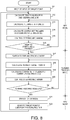
- Fig. 8 is a flowchart illustrating a flow of operation executed by the automatic steering device according to the embodiment of the present disclosure.
- the input receiver 11 may first receive the input of the plurality of target points P by the user, and store the target point information indicative of the positions of the received target points P in the memory 12 (Step S11).
- the route calculator 13 may calculate the traveling route R, for example, based on the target point information stored in the memory 12. Specifically, the route calculator 13 may identify, among the plurality of target points P indicated by the target point information, the target point P1 via which the ship 10 goes first, and the target point P2 via which the ship 10 goes next, and then calculate the route Q1, the route Q2, and the route R12 based on the positions of the identified target points P1 and P2.
- the route calculator 13 may then calculate the veering angle ⁇ t which is an angle formed by the straight line L1 passing through the current position P0 of the ship 10 and the target point P1 and the straight line L2 passing through the target point P1 and the target point P2, for example, based on the positional information received from the GPS receiver 102 (Step S12).
- the route calculator 13 may calculate the veering start line Lx based on the calculated traveling route R (Step S13).
- the command steering angle calculating module 23 may calculate the course setting ⁇ 0[n] which satisfies Formula (9), for example, based on the bow direction ⁇ [n] indicated by the bow direction information received from the direction sensor 103. The command steering angle calculating module 23 may then calculate the command steering angle to the steering mechanism 104 based on the calculated new course setting ⁇ 0[n], and output the command steering angle information indicative of the calculated command steering angle to the steering controlling module 15 (Step S14).
- the steering controlling module 15 may receive the command steering angle information from the command steering angle calculating module 23, and control the steering mechanism 104 so that the steering angle of the steering mechanism 104 becomes the command steering angle indicated by the command steering angle information to cause the ship 10 to travel in the NAV mode (Step S15).
- the mode determining module 21 of the processor 14 may examine, for example, the distance between the veering start line Lx, which is calculated by the route calculator 13, and the current position P0 of the ship 10. If the mode determining module 21 determines that the ship 10 has not passed the veering start line Lx ("NO" at Step S16), it may then continue the traveling in the NAV mode of the ship 10 (Steps S13-S16).
- the mode determining module 21 determines that the ship 10 passed the veering start line Lx ("YES" at Step S16), it may then notify to the intermediate waypoint calculating module 22 and the command steering angle calculating module 23 that the traveling mode of the ship 10 is switched from the NAV mode to the turning tracking mode (Step S17).
- the intermediate waypoint calculating module 22 may calculate the position of the intermediate waypoint S using Formulas (4) to (8), and then output to the command steering angle calculating module 23 the intermediate waypoint information indicative of the calculated position (Step S18).
- the command steering angle calculating module 23 may then examine the current position P0 of the ship 10, for example, based on the positional information received from the GPS receiver 102.
- the command steering angle calculating module 23 may then calculate the course setting ⁇ 0[n] using Formulas (10) to (12). On the other hand, if the ship 10 passed the boundary point T1, the command steering angle calculating module 23 may then calculate the course setting ⁇ 0[n] using Formulas (10), (11), and (13).
- the command steering angle calculating module 23 may then calculate the command steering angle to the steering mechanism 104 based on the calculated new course setting ⁇ 0[n], and output the command steering angle information indicative of the calculated command steering angle to the steering controlling module 15 (Step S19).
- the steering controlling module 15 may receive the command steering angle information from the command steering angle calculating module 23, and control the steering mechanism 104 so that the steering angle of the steering mechanism 104 becomes the command steering angle indicated by the command steering angle information (Step S20).
- the mode determining module 21 may determine whether the turning tracking mode is to be ended, for example, based on the positional information received from the GPS receiver 102 (Step S21). If the mode determining module 21 determines that, for example, the ship 10 has not passed the boundary point T2, it may then determine that the turning tracking mode is to be continued ("NO" at Step S21), and continue the travelling in the turning tracking mode of the ship 10 (Steps S18-S21).
- the mode determining module 21 determines that, for example, the ship 10 passed the boundary point T2, it may then determine that the turning tracking mode is to be ended ("YES" at Step S21), and notify to the intermediate waypoint calculating module 22 and the command steering angle calculating module 23 that the traveling mode of the ship 10 is switched from the turning tracking mode to the NAV mode (Step S22).
- the route calculator 13 may identify, among the plurality of target points P indicated by the target point information stored in the memory 12, the target point P3 via which the ship 10 goes next of the target point P2, as the target point to be used for the generation of the new traveling route R (Step S23). The route calculator 13 may then newly calculate the traveling route R and the veering angle ⁇ t based on the positions of the target point P2 and the target point P3 (Step S12). Then, the operation after Step S13 may be again executed.
- Step S18 the calculation of the intermediate waypoint S by the intermediate waypoint calculating module 22 (Step S18) and the determination of whether the turning tracking mode is to be ended by the mode determining module 21 (Step S21) may be executed asynchronously.
- the ship when causing the ship to travel along the traveling route connecting the plurality of preset target points, the ship may be unable to travel along the desired route after the start of veering due to the external factors, such as waves.
- the route calculator 13 may calculate the route R12 of the ship 10 based on the positions of the plurality of target points P.
- the intermediate waypoint calculating module 22 may calculate the intermediate waypoint S ahead of the ship 10.
- the command steering angle calculating module 23 may calculate the command steering angle based on the positional relation between the route R12 calculated by the route calculator 13 and the intermediate waypoint S calculated by the intermediate waypoint calculating module 22.
- the steering controlling module 15 may then control the steering mechanism 104 of the ship 10 based on the command steering angle calculated by the command steering angle calculating module 23.
- the command steering angle when the ship 10 arrives at the intermediate waypoint S can be calculated prior to arriving of the ship 10 at the intermediate waypoint S. For this reason, for example, even if it takes a time for the ship 10 to actually start the turning according to the command steering angle after the start of the control of the steering mechanism 104 according to the command steering angle, the turning can be started at the desired point more certainly.
- the traveling along the route R12 can be performed more accurately.
- the intermediate waypoint calculating module 22 may calculate the intermediate waypoint S based on the response of the ship 10 to the command steering angle.
- the position of the intermediate waypoint S can be calculated more accurately in consideration of the operating time according to the performance of the ship 10.
- the intermediate waypoint calculating module 22 may calculate the intermediate waypoint S based on the ship speed v.
- the more accurate position of the intermediate waypoint S can be calculated according to the current ship speed v.
- the intermediate waypoint calculating module 22 may calculate the intermediate waypoint S based on the course setting ⁇ 0[n-1] of the ship 10 and the current bow direction ⁇ [n] of the ship 10.
- the command steering angle calculating module 23 may calculate the command steering angle based on the tangent direction ⁇ st at the intersection In of the straight line Lcs passing through the center C of the circle having the route R12 as its part and the intermediate waypoint S, and the route R12.
- the command steering angle calculating module 23 may calculate the command steering angle further based on the distance REs between the intermediate waypoint S and the intersection In.
- the command steering angle calculating module 23 may calculate and update the command steering angle periodically or irregularly.
- the command steering angle calculating module 23 may change the method of calculating the command steering angle from the calculation method without using the indirect destination point S into the calculation method using the indirect destination point S, before and after the ship 10 arrives at the veering start point X located before the boundary point T1 which is the starting position of the route R12.
- the command steering angle may be calculated by the simple arithmetic processing to reduce the operation load, and, on the other hand, when the route to travel is an arc, the command steering angle can be calculated more accurately by the arithmetic processing using the differential coefficient etc., to cause the ship to travel on the traveling route.
- the steering controlling module 15 may start the control of the steering mechanism 104 based on the command steering angle, before the ship 10 starts the traveling of the arc-shaped route R12.
- the ship 10 can start more accurately the traveling along the route R12.
- the display signal generating module 16 may generate the display signal for displaying the route R12 and the intermediate waypoint S on the external apparatus.
- the positions of the route R12 and the intermediate waypoint S can be easily grasped by checking the screen displayed on the monitor of the external apparatus.
- the route calculator 13 may first calculate the route R12 of the ship 10 based on the positions of the plurality of target points P.
- the intermediate waypoint calculating module 22 may calculate the intermediate waypoint S ahead of the ship 10.
- the command steering angle calculating module 23 may calculate the command steering angle based on the positional relation between the route R12 calculated by the route calculator 13 and the intermediate waypoint S calculated by the intermediate waypoint calculating module 22.
- the steering controlling module 15 may control the steering mechanism 104 of the ship 10 based on the command steering angle calculated by the command steering angle calculating module 23.
- the command steering angle when the ship 10 arrives at the intermediate waypoint S can be calculated before the ship 10 arrives at the intermediate waypoint S. For this reason, for example, even if it takes a time for the ship 10 to actually start the turning according to the command steering angle after the start of the control of the steering mechanism 104 according to the command steering angle, the turning can be started at the desired point more certainly.
- the traveling along the route R12 can be performed more accurately.
Abstract
Description
- The present disclosure relates to an automatic steering device, an automatic steering method, and an automatic steering program.
- Conventionally, a technology related to automatic steering which causes a ship to travel along a traveling route connecting a plurality of preset target points has been developed. For example,
JP1995-242199A JP2005-178434A - However, after the veering is started, the ship may not be able to travel along the desired route due to external factors, such as waves.
- The present disclosure is made in view of solving the above problem, and one purpose thereof is to provide an automatic steering device, an automatic steering method, and an automatic steering program, capable of causing a ship to more accurately travel along a route to turn a ship.
- According to one aspect of the present disclosure, an automatic steering device may comprise a route calculator, an intermediate waypoint calculating module, a command steering angle calculating module, and a steering controlling module. The route calculator may calculate a route of a ship based on positions of a plurality of target points. The intermediate waypoint calculating module may calculate an intermediate waypoint ahead of the ship. The command steering angle calculating module may calculate a command steering angle based on a positional relation between the route and the intermediate waypoint. The steering controlling module may control a steering mechanism of the ship based on the command steering angle.
- The intermediate waypoint calculating module calculates the intermediate waypoint based on a response of the ship to the command steering angle.
- The intermediate waypoint calculating module calculates the intermediate waypoint based on a traveling speed of the ship.
- The intermediate waypoint calculating module calculates the intermediate waypoint based on a course setting of the ship and a current course of the ship.
- The command steering angle calculating module calculates the command steering angle based on a tangent direction at an intersection of a straight line passing through the center of a circle having the route as a part thereof and the intermediate waypoint, and the route.
- The command steering angle calculating module calculates the command steering angle further based on a distance between the intermediate waypoint and the intersection.
- The command steering angle calculating module calculates and updates the command steering angle periodically or irregularly.
- The command steering angle calculating module changes a method of calculating the command steering angle from a calculating method without using the indirect destination point into a calculation method using the indirect destination point, before and after the ship arrives at a veering start point before a starting position of the route.
- The steering controlling module starts the control of the steering mechanism based on the command steering angle before the ship starts traveling on an arc-shaped route. A display signal generating module configured to generate a display signal of the route and the intermediate waypoint.
- According to this configuration in which the intermediate waypoint which is the passing position of the ship is estimated, and the command steering angle is calculated based on the positional relation between the estimated intermediate waypoint and the route, the command steering angle when the ship arrives at the intermediate waypoint can be calculated prior to arriving of the ship at the intermediate waypoint. For this reason, for example, even if it takes a time for the ship to actually start the turning according to the command steering angle after the start of the control of the steering mechanism according to the command steering angle, the turning can be started at the desired point more certainly. Therefore, the traveling along the route can be performed more accurately.
- According to the present disclosure, the traveling along the route can be performed more accurately.
- The present disclosure is illustrated by way of example and not by way of limitation in the figures of the accompanying drawings, in which like reference numerals indicate like elements and in which:
-
Fig. 1 is a view illustrating a configuration of an automatic steering system according to one embodiment of the present disclosure; -
Fig. 2 is a view illustrating one example of a traveling route calculated by a route calculator according to the embodiment of the present disclosure; -
Fig. 3 is a view illustrating a comparative example of a route; -
Fig. 4 is a view illustrating one example of the route calculated by the route calculator according to the embodiment of the present disclosure; -
Fig. 5 is a view illustrating a method of calculating a command steering angle by a processor according to the embodiment of the present disclosure; -
Fig. 6 is a view (1/2) illustrating a relation between a position of an intermediate waypoint calculated by an intermediate waypoint calculating module of the processor according to the embodiment of the present disclosure, and a response of a ship to the command steering angle; -
Fig. 7 is a view (2/2) illustrating the relation between the position of the intermediate waypoint calculated by the intermediate waypoint calculating module of the processor according to the embodiment of the present disclosure, and the response of the ship to the command steering angle; and -
Fig. 8 is a flowchart illustrating a flow of operation executed by the automatic steering device according to the embodiment of the present disclosure. - Hereinafter, one embodiment of the present disclosure will be described with reference to the accompanying drawings. Note that the same reference characters are assigned to the same or corresponding parts throughout the figures to omit redundant description. Moreover, at least a part of the embodiment described below may be combined arbitrarily.
-
Fig. 1 is a view illustrating a configuration of an automatic steering system according to one embodiment of the present disclosure. - Referring to
Fig. 1 , anautomatic steering system 201 includes, for example, anautomatic steering device 101, aGPS receiver 102, adirection sensor 103, and asteering mechanism 104. - The
GPS receiver 102 may receive positioning signals from a plurality of GPS antennas (not illustrated) fixed to a ship 10 (hereinafter, referred to as "the ship" to be distinguished from other ships), detect a current position of theship 10, and transmit positional information indicative of the detected position of theship 10 to theautomatic steering device 101. Note that the present disclosure may be applied to ships which typically travels on water or sea and may be referred to as surface ships, and may also be applied to other types of ships, which may include boats, dinghies, watercraft, and vessels. Further, the present disclosure may also be applied, if applicable, to submarines, aircrafts, and spaceships, as well as any types of vehicles which travel on the ground, such as automobiles, motorcycles, and ATVs. - The
direction sensor 103 may measure a current course of theship 10, i.e., a bow direction ψ[n] based on, for example, a relative relation of a plurality of positions of theship 10 detected by the respective GPS antennas, and transmit bow direction information indicative of the measured bow direction ψ[n] to theautomatic steering device 101. - The
automatic steering device 101 may include aninput receiver 11, amemory 12, aroute calculator 13, and aprocessor 14. Theprocessor 14 may include amode determining module 21, an intermediatewaypoint calculating module 22, a command steeringangle calculating module 23, asteering controlling module 15, and a displaysignal generating module 16. - The
input receiver 11 may receive settings of a plurality of target points P. For example, theinput receiver 11 stores in thememory 12 target point information indicative of positions of a plurality of target points P inputted by a user through a keyboard etc. - The
route calculator 13 may calculate a traveling route R based on the target point information stored in thememory 12. Theroute calculator 13 may store route information indicative of the calculated traveling route R in thememory 12. - The
mode determining module 21 may determine a traveling mode of theship 10 based on, for example, the positional information of theship 10 received from theGPS receiver 102. - The intermediate
waypoint calculating module 22 may calculate and update an intermediate waypoint S ahead of theship 10, for example, periodically or irregularly, when the traveling mode determined by themode determining module 21 is a turning tracking mode described later. - The command steering
angle calculating module 23 may newly calculate and update a course setting ψ0[n] for causing theship 10 to travel along the traveling route R which is indicated by the route information stored in thememory 12, for example, each time the intermediate waypoint S is updated. - The command steering
angle calculating module 23 may calculate a command steering angle based on the latest course setting ψ0[n] each time the course setting ψ0[n] is updated, and output command steering angle information indicative of the calculated command steering angle to thesteering controlling module 15. - In response to the command steering angle information outputted from the command steering
angle calculating module 23, thesteering controlling module 15 may control a steering angle etc. of thesteering mechanism 104 based on the command steering angle indicated by the command steering angle information. - The display
signal generating module 16 may generate a display signal for displaying on an external apparatus (not illustrated) the traveling route R calculated by theroute calculator 13 and the intermediate waypoint S calculated by the intermediatewaypoint calculating module 22. - In more detail, the display
signal generating module 16 may generate the display signal including the route information stored in thememory 12 and the positional information on the intermediate waypoint S calculated by the intermediatewaypoint calculating module 22, and then transmit the generated display signal to an external apparatus. The external apparatus may receive the display signal transmitted from the displaysignal generating module 16, and then display, for example, a screen including the traveling route R and the intermediate waypoint S on a monitor of the ship based on the route information and the positional information on the intermediate waypoint S included in the received display signal. - Note that the
automatic steering system 201 may further include other apparatuses, in addition to theautomatic steering device 101, theGPS receiver 102, thedirection sensor 103, and thesteering mechanism 104. Moreover, theautomatic steering system 201 is not limited to such a configuration including all of theautomatic steering device 101, theGPS receiver 102, thedirection sensor 103, and thesteering mechanism 104. -
Fig. 2 is a view illustrating one example of the traveling route calculated by the route calculator according to the embodiment of the present disclosure. - Referring to
Fig. 2 , theroute calculator 13 identifies, for example, a target point (waypoint) P1 via which theship 10 goes first, and a target point (waypoint) P2 via which theship 10 goes next, among the plurality of target points P indicated by the target point information stored in thememory 12. Theroute calculator 13 may then calculate a route Q1 from the current position P0 of theship 10 to the target point P1 and a route Q2 from the target point P1 to the target point P2 based on the respective positions of the identified target points P1 and P2. - The
route calculator 13 may also calculate an arc-shaped route R12 via which theship 10 goes when theship 10 changes the route from the route Q1 to the route Q2. Here, one example of the route R12 calculated by theroute calculator 13 will be described. -
Fig. 3 is a view illustrating a comparative example of the route.Fig. 4 is a view illustrating one example of the route calculated by the route calculator according to the embodiment of the present disclosure.Fig. 3 illustrates a route R12 in a case where theship 10 arrives at the target point P1, and then starts turning toward the target point P2. Moreover,Fig. 4 illustrates a route R12 in a case where theship 10 starts turning before arriving at the target point P1. - Comparing the route R12 illustrated in
Fig. 3 with the route R12 illustrated inFig. 4 , the route R12 illustrated inFig. 4 is better and desirable in fuel consumption, riding comfort, etc. of theship 10. - Referring again to
Fig. 2 , theroute calculator 13 may then calculate, as the route R12, a route R12 which is a part of a circle inscribed inside a straight line L1 passing through the current position P0 of theship 10 and the target point PI, and a straight line L2 passing through the target point P1 and the target point P2. - In more detail, the
route calculator 13 may calculate an angle θt [deg] formed by the straight line L1 and the straight line L2 (hereinafter, referred to as a "veering angle"). - If a traveling speed of the ship 10 (ship speed) is v [m/s], and for example, a turn rate of the
ship 10 which is set by the user is Tr [deg/sec], a relation of a turning radius Dr which is a radius of the route R12, the ship speed v, and the turn rate Tr may satisfy the following Formula (1).
- The
route calculator 13 may calculate the turning radius Dr using Formula (1). - Here, a boundary point between the route Q1 and the route R12 is T1, and a boundary point between the route Q2 and the route R12 is T2. The
route calculator 13 may calculate a distance D1 between the boundary point T1 and the target point PI, a distance D2 between the target point P1 and the boundary point T2 according to the following Formula (2) using the veering angle θt and the turning radius Dr which are calculated.
- The
route calculator 13 may also calculate the positions of the boundary point T1 and the boundary point T2 based on the calculated distance D1 and distance D2, and the position of the target point P1. Thus, theroute calculator 13 can calculate the route R12 connecting the boundary point T1 and the boundary point T2 which are calculated. - The route Q1 up to the boundary point T1, the route R12 from the boundary point T1 to the boundary point T2, and the route Q2 from the boundary point T2, which are calculated by the
route calculator 13, may correspond to the traveling route R. - Here, when the
ship 10 travels along the route R12, the traveling along the route R12 may be unable to be started if the start timing of the veering is too early or too late. For this reason, theroute calculator 13 may calculate a point which is located before the boundary point T1 and at which the veering is to be started (hereinafter, referred to as a "veering start point X"). - In more detail, for example, a time t2 is required until a constant turning begins after the
ship 10 begins turning a rudder, i.e., until a turning at the specified turn rate Tr begins. Moreover, for example, a time t3 is required until the command steering angle for thesteering mechanism 104 becomes a steering angle which can obtain a turning angular velocity at the turn rate Tr after the control for veering by thesteering controlling module 15 illustrated inFig. 1 is started. - The time t2 and the time t3 may be based on the response of the
ship 10 to the command steering angle, specifically, based on at least one of the following performance T and the turning performance K of theship 10. The following performance T and the turning performance K are, for example, actual measurements obtained by prior examinations using theship 10, and are stored beforehand in thememory 12. Note that the following performance T and the turning performance K may be, for example, actual measurements obtained by prior examinations using a ship other than theship 10. - The
steering controlling module 15 may start the control of thesteering mechanism 104 at a timing a period of time tx (=t2+t3) before the timing at which theship 10 passes through the boundary point T1. Thus, theship 10 can start more accurately the travel along the route R12. - The distance Dx between the veering start point X and the point T1 may satisfy the following Formula (3).

- The
route calculator 13 may calculate the position of the veering start point X according to Formula (3). Theroute calculator 13 may also calculate a veering start line Lx which is a straight line passing through the calculated veering start point X and perpendicular to the route Q1. - The position of the veering start line Lx typically varies according to the ship speed v etc. For this reason, the
route calculator 13 may calculate and update the veering start line Lx, for example, periodically or irregularly. - The
route calculator 13 may also calculate the position of an intersection In of a straight line Lct1 which passes through the boundary point T1 and intersects perpendicularly to the route Q1, and a straight line Lct2 which passes through the boundary point T2 and intersects perpendicularly to the route Q2, as the position of a center C of a circle having the route R12 as its part. - The
route calculator 13 may then store in thememory 12 the route information indicative of the calculated traveling route R, the position of the boundary point T1, the position of the boundary point T2, the position of the center C, the position of the latest veering start line Lx, and the turning radius Dr. -
Fig. 5 is a view illustrating a method of calculating the command steering angle by the processor according to the embodiment of the present disclosure. - Referring to
Fig. 5 , theprocessor 14 may estimate a passing position forward of theship 10 after theship 10 passes the veering start line Lx, and then calculate a direction setting ψ0[n] based on a positional relation between the estimated passing position and the traveling route R. - Specifically, the
processor 14 may calculate the intermediate waypoint S ahead of theship 10 based on a current course setting ψ0[n-1], the bow direction ψ[n], and the ship speed v. Theprocessor 14 may also calculate a course setting ψ0[n] for causing theship 10 to travel along the route R12 in a case where theship 10 is located at the calculated intermediate waypoint S. - The
processor 14 may then calculate the command steering angle based on the calculated course setting ψ0[n]. The details of the calculation of the course setting ψ0[n] by theprocessor 14 will be described later. - Referring to
Figs. 1 and5 , themode determining module 21 of theprocessor 14 may determine the traveling mode of theship 10 based on, for example, the positional information received from theGPS receiver 102, and the route information stored in thememory 12. Specifically, themode determining module 21 may determine a NAV mode as the traveling mode of theship 10, if it determines that theship 10 is traveling before the veering start line Lx. - The
mode determining module 21 may also determine a turning tracking mode as the traveling mode of theship 10, if it determines that theship 10 is traveling between the veering start line Lx and the boundary point T2. - Note that, instead of determining the traveling mode based on the positional information received from the
GPS receiver 102, themode determining module 21 may determine the traveling mode based on the bow direction ψ[n] indicated by the bow direction information received from thedirection sensor 103, or a direction of a travel locus of the ship 10 (COG: Course of Ground). - For example, the
mode determining module 21 may calculate a difference between a direction from the target point P1 to the target point P2 and the bow direction ψ[n] periodically or irregularly, and when the calculated difference becomes less than a given value, change the traveling mode from the turning tracking mode to the NAV mode. - The intermediate
waypoint calculating module 22 may calculate the intermediate waypoint S, when a given mode, i.e., the turning tracking mode is determined as the traveling mode by themode determining module 21. On the other hand, if the NAV mode is determined as the traveling mode by themode determining module 21, the intermediatewaypoint calculating module 22 may not calculate the intermediate waypoint S. - When calculating the intermediate waypoint S, the intermediate
waypoint calculating module 22 may calculate the intermediate waypoint S based on, for example, the current course setting ψ0[n-1] and the bow direction ψ[n]. - Specifically, the intermediate
waypoint calculating module 22 may calculate average values of the course setting ψ0[n-1] and the bow direction ψ[n] by using ψs[n] as a direction from the current position of theship 10 to the intermediate waypoint S. That is, the intermediatewaypoint calculating module 22 may calculate the direction ψs[n] according to the following Formula (4).
- The intermediate
waypoint calculating module 22 may also calculate a distance Ds from the current position P0 of theship 10 to the intermediate waypoint S according to the following Formula (5).
- In Formula (5), v is the ship speed. Moreover, Ts is an estimated time required for travelling from the current position P0 of the
ship 10 to the intermediate waypoint S. - The estimated time Ts may be a period of time based on the response of the ship to the command steering angle, more specifically, at least one of the following performance T and the turning performance K of the
ship 10. The estimated time Ts satisfies, for example, the following Formula (6).
- In Formula (6), Ts_base is a reference value of the estimated time. Moreover, T_base is a reference value of the following performance T. Moreover, K_base is a reference value of the turning performance K. Ts_base, T_base, and K_base are values acquired from simulations or experiments.
- The intermediate
waypoint calculating module 22 may also calculate the position of the intermediate waypoint S based on the current position P0 of theship 10, the calculated direction ψs[n], and the calculated distance Ds. Here, the latitude and longitude of the current position of theship 10 are "N_lat" and "N_lon," respectively, and the latitude and longitude of the intermediate waypoint S are "S_lat" and "S_lon," respectively. - In this case, latitude S_lat and longitude S_lon of the intermediate waypoint S may satisfy the following Formulas (7) and (8), respectively.


- Here, a relation between the response of the ship to the command steering angle and the position of the intermediate waypoint S will be described.
-
Fig. 6 is a view (1/2) illustrating a relation between the position of the intermediate waypoint calculated by the intermediate waypoint calculating module of the processor according to the embodiment of the present disclosure, and the response of the ship to the command steering angle. -
Fig. 7 is a view (2/2) illustrating the relation between the position of the intermediate waypoint calculated by the intermediate waypoint calculating module of the processor according to the embodiment of the present disclosure, and the response of the ship to the command steering angle. -
Fig. 6 illustrates the position of the intermediate waypoint S when the response of theship 10 to the command steering angle is good, i.e., when the values of the following performance T and the turning performance K are large.Fig. 7 illustrates the position of the intermediate waypoint S when the response of theship 10 to the command steering angle is poor, i.e., when the values of the following performance T and the turning performance K are small. - Referring to
Figs. 6 and7 , when the response of theship 10 to the command steering angle is good, since the distance Ds becomes shorter, the position of the intermediate waypoint S may be calculated as a position close to the current position P0 of theship 10. On the other hand, when the response of theship 10 to the command steering angle is poor, since the distance Ds becomes longer, the position of the intermediate waypoint S may be calculated as a position distant from the current position P0 of theship 10. - Thus, the intermediate
waypoint calculating module 22 can calculate the position of the intermediate waypoint S more appropriately in consideration of the response of theship 10 to the command steering angle. - Note that the intermediate
waypoint calculating module 22 is not limited to such a configuration to calculate the intermediate waypoint S using the response of theship 10 to the command steering angle, but may calculate the intermediate waypoint S, for example, using an arbitrary value instead of the response. - Moreover, the intermediate
waypoint calculating module 22 is not limited to such a configuration to calculate the intermediate waypoint S using the ship speed v, but may calculate the intermediate waypoint S, for example, using an arbitrary value instead of the ship speed v. - Moreover, the intermediate
waypoint calculating module 22 is not limited to such a configuration to calculate the intermediate waypoint S using the course setting ψ0[n-1] and the bow direction ψ[n], but may calculate the intermediate waypoint S without using at least one of of the course setting ψ0[n-1] and the bow direction ψ[n]. - Referring again to
Fig. 5 , the command steeringangle calculating module 23 may calculate the course setting ψ0[n], for example, using a technique of feedback control, such as a PID (Proportional Integral Differential) control, and then calculate the command steering angle based on the calculated course setting ψ0[n]. - The command steering
angle calculating module 23 may also change the method of calculating the command steering angle according to the traveling mode determined by themode determining module 21. As described above, themode determining module 21 may change the traveling mode between before and after the timing at which theship 10 is located on the veering start line Lx. For this reason, the command steeringangle calculating module 23 may change the method of calculating the course setting ψ0[n] and the command steering angle before and after the timing. In more detail, the command steeringangle calculating module 23 may change the method of calculating the command steering angle from a calculating method without using the indirect destination S into a calculation method using the indirect destination S, before and after the arrival of theship 10 at the veering start line Lx. - When the
ship 10 is traveling in the NAV mode, the command steeringangle calculating module 23 may calculate the course setting ψ0[n] based on the current bow direction ψ[n], and a deviation XTE of the route Q1 or the route Q2 and the current position P0 of the ship 10 (cross track error). - That is, the command steering
angle calculating module 23 may calculate the course setting ψ0[n] using the following Formula (9).
- In Formula (9), α is a proportional coefficient.
- Moreover, in Formula (9), when the current position P0 of the
ship 10 is deviated from the route Q1 or the route Q2 in the clockwise direction, a minus coefficient is adopted as α. On the other hand, when the current position P0 of theship 10 is deviated from the route Q1 or the route Q2 in the counterclockwise direction, a plus coefficient is adopted as α. - Moreover, the command steering
angle calculating module 23 may calculate the command steering angle to thesteering mechanism 104 based on the calculated course setting ψ0[n]. For example, the command steeringangle calculating module 23 calculates a value obtained by subtracting the bow direction ψ[n] from the course setting ψ0[n], as the command steering angle. The command steeringangle calculating module 23 may then output the command steering angle information indicative of the calculated command steering angle to thesteering controlling module 15. - The command steering
angle calculating module 23 may calculate and update the course setting ψ0[n] and the command steering angle periodically or irregularly, while theship 10 is traveling in the NAV mode. - The command steering
angle calculating module 23 examines, for example, the positional information received from theGPS receiver 102. If the command steeringangle calculating module 23 determines that theship 10 travels in the turning tracking mode, and travels between the veering start line Lx and the boundary point T1, it may then be calculated the course setting ψ0[n] based on the positions of the intermediate waypoint S and the center C, and the deviation XTE of the current position P0 of theship 10 from the route Q1. - In more details, the command steering
angle calculating module 23 may calculate a direction ψcs of a straight line Lcs passing through the center C and the intermediate waypoint S using the latitude S_lat and the longitude S_lon of the intermediate waypoint S, and the latitude C_lat and the longitude C_lon of the center C. - That is, the command steering
angle calculating module 23 may calculate the direction ψcs of the straight line Lcs using the following Formula (10).
- Moreover, the command steering
angle calculating module 23 may calculate a tangent direction ψst at the intersection In of the straight line Lcs and the route R12 using the calculated direction ψcs. The tangent direction ψst may satisfy the following Formula (11).
- The command steering
angle calculating module 23 may then calculate the course setting ψ0[n] using the calculated direction ψcs. The new course setting ψ0[n] may satisfy the following Formula (12).
- In Formula (12), when the current position P0 of the
ship 10 is deviated from the route Q1 in the clockwise direction, a minus coefficient is adopted as α, and when the current position P0 of theship 10 is deviated from the route Q1 in the counterclockwise direction, a plus coefficient is adopted as α. - Moreover, based on the calculated course setting ψ0[n], the command steering
angle calculating module 23 may calculate the command steering angle to thesteering mechanism 104, and then output command steering angle information indicative of the calculated command steering angle to thesteering controlling module 15. The command steeringangle calculating module 23 may calculate and updates the course setting ψ0[n] and the command steering angle periodically or irregularly, while theship 10 is traveling in the turning tracking mode. - The command steering
angle calculating module 23 examines, for example, the positional information received from theGPS receiver 102. If the command steeringangle calculating module 23 determines that theship 10 travels in the turning tracking mode, and travels between the boundary point T1 and the boundary point T2, it may then calculate the course setting ψ0[n] based on the positions of the intermediate waypoint S and the center C, and a deviation REs[n] of the current position P0 of theship 10 from the route R12. - In more detail, similar to the case of (b-1), the command steering
angle calculating module 23 may calculate the direction ψcs of the straight line Lcs passing through the center C and the intermediate waypoint S using the latitude S_lat and the longitude S_lon of the intermediate waypoint S, and the latitude C_lat and the longitude C_lon of the center C. - Moreover, the command steering
angle calculating module 23 may calculate the tangent direction ψst at the intersection In of the straight line Lcs and the route R12 using the calculated direction ψcs. - The command steering
angle calculating module 23 may then calculate the new course setting ψ0[n] using the calculated direction ψcs. The new course setting ψ0[n] may satisfy the following formulas (13) and (14).

- In Formula (13), REs[n] is a distance between the intermediate waypoint S and the intersection In, i.e., a distance between the intermediate waypoint S and the route R12. Moreover, in Formula (14), REs[n-1] is a distance between the intermediate waypoint S and the route R12 which are calculated previously.
- Moreover, in Formula (13), when the current position P0 of the
ship 10 is deviated from the route Q1 in the clockwise direction, a minus coefficient may be adopted, and when the current position P0 of theship 10 is deviated from the route Q1 in the counterclockwise direction, a plus coefficient may be adopted. - Moreover, the command steering
angle calculating module 23 may calculate the command steering angle to thesteering mechanism 104 based on the calculated course setting ψ0[n], and then output the command steering angle information indicative of the calculated command steering angle to thesteering controlling module 15. The command steeringangle calculating module 23 may calculate and update the course setting ψ0[n] and the command steering angle periodically or irregularly, while theship 10 is traveling in the turning tracking mode. - Note that the command steering
angle calculating module 23 may set a lower limit of the new course setting ψ0[n]. - For example, the intermediate waypoint S calculated two times before by the intermediate
waypoint calculating module 22 is set to S[n-2], the intermediate waypoint S calculated last time is set to S[n-1], and the newly calculated intermediate waypoint S is set to S[n]. Moreover, the direction from the intermediate waypoint S[n-2] to the intermediate waypoint S[n-1] is set to ψleg1, and the direction from the intermediate waypoint S[n-1] to the intermediate waypoint S[n] is set to ψleg2. - When the
ship 10 is turning in the clockwise direction, if the calculated course setting ψ0[n] satisfies the following Formula (15), the command steeringangle calculating module 23 may change the course setting ψ0[n] according to the following Formula (16).

- Moreover, when the
ship 10 is turning in the counterclockwise direction, if the calculated course setting ψ0[n] satisfies the following Formula (17), the command steeringangle calculating module 23 may change the course setting ψ0[n] according to the following Formula (18).

- Note that the command steering
angle calculating module 23 may be configured to calculate the command steering angle based on the positional relation between the route R12 and the intermediate waypoint S, and therefore, the method of calculating the command steering angle by the command steeringangle calculating module 23 is not limited to the method described above. - The
automatic steering device 101 may be provided with a computer, and a processor, such as a CPU in the computer, read a command steering angle calculation program including a part or all of steps of the following flowchart from, for example, thememory 12, and execute it. The command steering angle calculation program may also be installed from the outside. Moreover, the command steering angle calculation program may be distributed in a state where it is stored in a recording medium. -
Fig. 8 is a flowchart illustrating a flow of operation executed by the automatic steering device according to the embodiment of the present disclosure. - Referring to
Figs. 1 and8 , theinput receiver 11 may first receive the input of the plurality of target points P by the user, and store the target point information indicative of the positions of the received target points P in the memory 12 (Step S11). - Next, the
route calculator 13 may calculate the traveling route R, for example, based on the target point information stored in thememory 12. Specifically, theroute calculator 13 may identify, among the plurality of target points P indicated by the target point information, the target point P1 via which theship 10 goes first, and the target point P2 via which theship 10 goes next, and then calculate the route Q1, the route Q2, and the route R12 based on the positions of the identified target points P1 and P2. - The
route calculator 13 may then calculate the veering angle θt which is an angle formed by the straight line L1 passing through the current position P0 of theship 10 and the target point P1 and the straight line L2 passing through the target point P1 and the target point P2, for example, based on the positional information received from the GPS receiver 102 (Step S12). - Next, the
route calculator 13 may calculate the veering start line Lx based on the calculated traveling route R (Step S13). - Next, the command steering
angle calculating module 23 may calculate the course setting ψ0[n] which satisfies Formula (9), for example, based on the bow direction ψ[n] indicated by the bow direction information received from thedirection sensor 103. The command steeringangle calculating module 23 may then calculate the command steering angle to thesteering mechanism 104 based on the calculated new course setting ψ0[n], and output the command steering angle information indicative of the calculated command steering angle to the steering controlling module 15 (Step S14). - Next, the
steering controlling module 15 may receive the command steering angle information from the command steeringangle calculating module 23, and control thesteering mechanism 104 so that the steering angle of thesteering mechanism 104 becomes the command steering angle indicated by the command steering angle information to cause theship 10 to travel in the NAV mode (Step S15). - Next, the
mode determining module 21 of theprocessor 14 may examine, for example, the distance between the veering start line Lx, which is calculated by theroute calculator 13, and the current position P0 of theship 10. If themode determining module 21 determines that theship 10 has not passed the veering start line Lx ("NO" at Step S16), it may then continue the traveling in the NAV mode of the ship 10 (Steps S13-S16). - On the other hand, if the
mode determining module 21 determines that theship 10 passed the veering start line Lx ("YES" at Step S16), it may then notify to the intermediatewaypoint calculating module 22 and the command steeringangle calculating module 23 that the traveling mode of theship 10 is switched from the NAV mode to the turning tracking mode (Step S17). - Next, when the notice of switching the traveling mode to the turning tracking mode is received from the
mode determining module 21, the intermediatewaypoint calculating module 22 may calculate the position of the intermediate waypoint S using Formulas (4) to (8), and then output to the command steeringangle calculating module 23 the intermediate waypoint information indicative of the calculated position (Step S18). - Next, when the command steering
angle calculating module 23 receives from themode determining module 21 the notice of switching the traveling mode of theship 10 from the NAV mode to the turning tracking mode, and further receives the intermediate waypoint information from the intermediatewaypoint calculating module 22, it may then examine the current position P0 of theship 10, for example, based on the positional information received from theGPS receiver 102. - If the
ship 10 has not passed the boundary point T1, the command steeringangle calculating module 23 may then calculate the course setting ψ0[n] using Formulas (10) to (12). On the other hand, if theship 10 passed the boundary point T1, the command steeringangle calculating module 23 may then calculate the course setting ψ0[n] using Formulas (10), (11), and (13). - The command steering
angle calculating module 23 may then calculate the command steering angle to thesteering mechanism 104 based on the calculated new course setting ψ0[n], and output the command steering angle information indicative of the calculated command steering angle to the steering controlling module 15 (Step S19). - Next, the
steering controlling module 15 may receive the command steering angle information from the command steeringangle calculating module 23, and control thesteering mechanism 104 so that the steering angle of thesteering mechanism 104 becomes the command steering angle indicated by the command steering angle information (Step S20). - Next, the
mode determining module 21 may determine whether the turning tracking mode is to be ended, for example, based on the positional information received from the GPS receiver 102 (Step S21). If themode determining module 21 determines that, for example, theship 10 has not passed the boundary point T2, it may then determine that the turning tracking mode is to be continued ("NO" at Step S21), and continue the travelling in the turning tracking mode of the ship 10 (Steps S18-S21). - On the other hand, if the
mode determining module 21 determines that, for example, theship 10 passed the boundary point T2, it may then determine that the turning tracking mode is to be ended ("YES" at Step S21), and notify to the intermediatewaypoint calculating module 22 and the command steeringangle calculating module 23 that the traveling mode of theship 10 is switched from the turning tracking mode to the NAV mode (Step S22). - Next, the
route calculator 13 may identify, among the plurality of target points P indicated by the target point information stored in thememory 12, the target point P3 via which theship 10 goes next of the target point P2, as the target point to be used for the generation of the new traveling route R (Step S23). Theroute calculator 13 may then newly calculate the traveling route R and the veering angle θt based on the positions of the target point P2 and the target point P3 (Step S12). Then, the operation after Step S13 may be again executed. - Note that, the calculation of the intermediate waypoint S by the intermediate waypoint calculating module 22 (Step S18) and the determination of whether the turning tracking mode is to be ended by the mode determining module 21 (Step S21) may be executed asynchronously.
- Meanwhile, when causing the ship to travel along the traveling route connecting the plurality of preset target points, the ship may be unable to travel along the desired route after the start of veering due to the external factors, such as waves.
- Regarding this problem, in the
automatic steering device 101 according to the embodiment of the present disclosure, theroute calculator 13 may calculate the route R12 of theship 10 based on the positions of the plurality of target points P. The intermediatewaypoint calculating module 22 may calculate the intermediate waypoint S ahead of theship 10. The command steeringangle calculating module 23 may calculate the command steering angle based on the positional relation between the route R12 calculated by theroute calculator 13 and the intermediate waypoint S calculated by the intermediatewaypoint calculating module 22. Thesteering controlling module 15 may then control thesteering mechanism 104 of theship 10 based on the command steering angle calculated by the command steeringangle calculating module 23. - Thus, since the intermediate waypoint S which is the passing position of the
ship 10 is estimated, and the command steering angle is calculated based on the positional relation between the estimated intermediate waypoint S and the route R12, the command steering angle when theship 10 arrives at the intermediate waypoint S can be calculated prior to arriving of theship 10 at the intermediate waypoint S. For this reason, for example, even if it takes a time for theship 10 to actually start the turning according to the command steering angle after the start of the control of thesteering mechanism 104 according to the command steering angle, the turning can be started at the desired point more certainly. - Therefore, in the
automatic steering device 101 according to the embodiment of the present disclosure, the traveling along the route R12 can be performed more accurately. - Moreover, in the
automatic steering device 101 according to the embodiment of the present disclosure, the intermediatewaypoint calculating module 22 may calculate the intermediate waypoint S based on the response of theship 10 to the command steering angle. - Thus, the position of the intermediate waypoint S can be calculated more accurately in consideration of the operating time according to the performance of the
ship 10. - Moreover, in the
automatic steering device 101 according to the embodiment of the present disclosure, the intermediatewaypoint calculating module 22 may calculate the intermediate waypoint S based on the ship speed v. - By such a configuration, the more accurate position of the intermediate waypoint S can be calculated according to the current ship speed v.
- Moreover, in the
automatic steering device 101 according to the embodiment of the present disclosure, the intermediatewaypoint calculating module 22 may calculate the intermediate waypoint S based on the course setting ψ0[n-1] of theship 10 and the current bow direction ψ[n] of theship 10. - By such a configuration, since the more accurate course of the
ship 10 can be grasped, the position of the intermediate waypoint S can be calculated more accurately. - Moreover, in the
automatic steering device 101 according to the embodiment of the present disclosure, the command steeringangle calculating module 23 may calculate the command steering angle based on the tangent direction ψst at the intersection In of the straight line Lcs passing through the center C of the circle having the route R12 as its part and the intermediate waypoint S, and the route R12. - By such a configuration, the course setting ψ0[n] when the
ship 10 arrives at the intermediate waypoint S can be calculated, without performing the complicated arithmetic processing. - Moreover, in the
automatic steering device 101 according to the embodiment of the present disclosure, the command steeringangle calculating module 23 may calculate the command steering angle further based on the distance REs between the intermediate waypoint S and the intersection In. - Thus, since the tangent direction ψst can be corrected using the distance REs which is the deviation of the intermediate waypoint S from the route R12, the more suitable command steering angle can be calculated.
- Moreover, in the
automatic steering device 101 according to the embodiment of the present disclosure, the command steeringangle calculating module 23 may calculate and update the command steering angle periodically or irregularly. - By such a configuration, the more suitable command steering angle according to the temporal change of the bow direction ψ[n] etc. of the
ship 10 can be calculated. - Moreover, in the
automatic steering device 101 according to the embodiment of the present disclosure, the command steeringangle calculating module 23 may change the method of calculating the command steering angle from the calculation method without using the indirect destination point S into the calculation method using the indirect destination point S, before and after theship 10 arrives at the veering start point X located before the boundary point T1 which is the starting position of the route R12. - By such a configuration, for example, when the route to travel is a straight line, the command steering angle may be calculated by the simple arithmetic processing to reduce the operation load, and, on the other hand, when the route to travel is an arc, the command steering angle can be calculated more accurately by the arithmetic processing using the differential coefficient etc., to cause the ship to travel on the traveling route.
- Moreover, in the
automatic steering device 101 according to the embodiment of the present disclosure, thesteering controlling module 15 may start the control of thesteering mechanism 104 based on the command steering angle, before theship 10 starts the traveling of the arc-shaped route R12. - By such a configuration, the
ship 10 can start more accurately the traveling along the route R12. - Moreover, in the
automatic steering device 101 according to the embodiment of the present disclosure, the displaysignal generating module 16 may generate the display signal for displaying the route R12 and the intermediate waypoint S on the external apparatus. - By such a configuration, for example, the positions of the route R12 and the intermediate waypoint S can be easily grasped by checking the screen displayed on the monitor of the external apparatus.
- Moreover, in the automatic steering method according to the embodiment of the present disclosure, the
route calculator 13 may first calculate the route R12 of theship 10 based on the positions of the plurality of target points P. Next, the intermediatewaypoint calculating module 22 may calculate the intermediate waypoint S ahead of theship 10. Next, the command steeringangle calculating module 23 may calculate the command steering angle based on the positional relation between the route R12 calculated by theroute calculator 13 and the intermediate waypoint S calculated by the intermediatewaypoint calculating module 22. Then, thesteering controlling module 15 may control thesteering mechanism 104 of theship 10 based on the command steering angle calculated by the command steeringangle calculating module 23. - Thus, by the method of estimating the intermediate waypoint S which is the passing position of the
ship 10 and calculating the command steering angle based on the positional relation between the estimated intermediate waypoint S and the route R12, the command steering angle when theship 10 arrives at the intermediate waypoint S can be calculated before theship 10 arrives at the intermediate waypoint S. For this reason, for example, even if it takes a time for theship 10 to actually start the turning according to the command steering angle after the start of the control of thesteering mechanism 104 according to the command steering angle, the turning can be started at the desired point more certainly. - Therefore, in the automatic steering method according to the embodiment of the present disclosure, the traveling along the route R12 can be performed more accurately.
- It should be thought that the above embodiment is merely illustration in all respects and not restrictive. The scope of the present disclosure is defined by not the above description but the claims, and it is intended to encompass the claims, and all the modifications within the scope and equivalents.
Claims (12)
- An automatic steering device (101), comprising:a route calculating module (13) configured to calculate a route to turn a ship (10) based on positions of a plurality of waypoints (P, PI, P2);an intermediate waypoint calculating module (22) configured to calculate an intermediate waypoint (S) ahead of the ship (10);a command steering angle calculating module (23) configured to calculate a command steering angle based on a positional relation between the route and the intermediate waypoint (S); anda steering controlling module (15) configured to control a steering mechanism (104) of the ship (10) based on the command steering angle.
- The automatic steering device (101) of claim 1, wherein the intermediate waypoint calculating module (22) calculates the intermediate waypoint (S) based on a response of the ship (10) to the command steering angle.
- The automatic steering device (101) of claim 1 or 2, wherein the intermediate waypoint calculating module (22) calculates the intermediate waypoint (S) based on a speed of the ship (10).
- The automatic steering device (101) of any of the previous claims, wherein the intermediate waypoint calculating module (22) calculates the intermediate waypoint (S) based on a set heading of the ship (10) and a current heading of the ship (10).
- The automatic steering device (101) of any of the previous claims, wherein the command steering angle calculating module (23) calculates the command steering angle based on a tangent direction at an intersection of a straight line and the route, the straight line passing through a center of a circle comprising the route and the intermediate waypoint (S).
- The automatic steering device (101) of claim 5, wherein the command steering angle calculating module (23) calculates the command steering angle further based on a distance between the intermediate waypoint (S) and the intersection.
- The automatic steering device (101) of any of the previous claims, wherein the command steering angle calculating module (23) update the calculation of the command steering angle periodically or aperiodically.
- The automatic steering device (101) of any of the previous claims, wherein the command steering angle calculating module (23) changes a method of calculating the command steering angle from a calculating method not using the intermediate waypoint into a calculation method using the intermediate waypoint, when the ship (10) arrives at a veering start point before a starting position of the route.
- The automatic steering device (101) of any of the previous claims, wherein the steering controlling module (15) starts the control of the steering mechanism (104) based on the command steering angle before the ship (10) starts traveling on the route having an arc shape.
- The automatic steering device (101) of any of the previous claims, further comprising a display signal generating module (16) configured to generate a display signal of the route and the intermediate waypoint (S).
- An automatic steering method using an automatic steering device (101) comprising:calculating a route to turn a ship (10) based on positions of a plurality of waypoints (P, PI, P2);calculating an intermediate waypoint (S) ahead of the ship (10);calculating a command steering angle based on a positional relation between the route and the intermediate waypoint (S); andcontrolling a steering mechanism (104) of the ship (10) based on the command steering angle.
- A non-transitory computer-readable medium having stored thereon computer-executable instructions which, when executed by a computer, cause the computer to:calculate a route to turn a ship (10) based on positions of a plurality of waypoints (P, P1, P2);calculate an intermediate waypoint (S) ahead of the ship (10);calculate a command steering angle based on a positional relation between the route and the intermediate waypoint (S); andcontrol a steering mechanism (104) of the ship (10) based on the command steering angle.
Applications Claiming Priority (1)
| Application Number | Priority Date | Filing Date | Title |
|---|---|---|---|
| JP2018091341A JP2019196103A (en) | 2018-05-10 | 2018-05-10 | Automatic steering device, automatic steering method, and automatic steering program |
Publications (1)
| Publication Number | Publication Date |
|---|---|
| EP3566942A1 true EP3566942A1 (en) | 2019-11-13 |
Family
ID=66476486
Family Applications (1)
| Application Number | Title | Priority Date | Filing Date |
|---|---|---|---|
| EP19173505.9A Pending EP3566942A1 (en) | 2018-05-10 | 2019-05-09 | Automatic steering device, automatic steering method and automatic steering program |
Country Status (3)
| Country | Link |
|---|---|
| US (1) | US11383813B2 (en) |
| EP (1) | EP3566942A1 (en) |
| JP (1) | JP2019196103A (en) |
Families Citing this family (4)
| Publication number | Priority date | Publication date | Assignee | Title |
|---|---|---|---|---|
| WO2020129226A1 (en) * | 2018-12-20 | 2020-06-25 | 富士通株式会社 | Navigation assistance method, navigation assistance device, and navigation assistance program |
| KR20230011310A (en) | 2020-05-15 | 2023-01-20 | 고쿠리츠겐큐카이하츠호진 가이죠·고완·고쿠기쥬츠겐큐죠 | Ship's automatic guidance method, ship's automatic guidance program, ship's automatic guidance system and ship |
| US11531341B2 (en) * | 2020-06-12 | 2022-12-20 | Garmin Switzerland Gmbh | Marine autopilot system |
| US20220390948A1 (en) * | 2021-06-08 | 2022-12-08 | Dominico P. Julian | Autonomous Transportation Of Cargo |
Citations (4)
| Publication number | Priority date | Publication date | Assignee | Title |
|---|---|---|---|---|
| JPH07242199A (en) | 1994-03-04 | 1995-09-19 | Furuno Electric Co Ltd | Automatic steering method and device therefor |
| JP2005178434A (en) | 2003-12-16 | 2005-07-07 | Furuno Electric Co Ltd | Automatic steering control device and automatic steering device |
| JP2009248897A (en) * | 2008-04-10 | 2009-10-29 | Tokyo Keiki Inc | Automatic ship steering device |
| EP3214522A1 (en) * | 2016-03-01 | 2017-09-06 | Brunswick Corporation | Vessel control method and system |
Family Cites Families (4)
| Publication number | Priority date | Publication date | Assignee | Title |
|---|---|---|---|---|
| JP3874827B2 (en) | 1994-11-28 | 2007-01-31 | 株式会社トキメック | Ship automatic steering system |
| JPH09207889A (en) | 1995-11-27 | 1997-08-12 | Tokimec Inc | Automatically steering device for ship |
| US8265812B2 (en) * | 2010-11-24 | 2012-09-11 | William M Pease | System and method for a marine vessel autopilot |
| JP2014004911A (en) | 2012-06-25 | 2014-01-16 | Tokyo Univ Of Marine Science & Technology | Method for maintaining water route of ship with nonlinear auto-regressive model |
-
2018
- 2018-05-10 JP JP2018091341A patent/JP2019196103A/en active Pending
-
2019
- 2019-05-08 US US16/406,861 patent/US11383813B2/en active Active
- 2019-05-09 EP EP19173505.9A patent/EP3566942A1/en active Pending
Patent Citations (5)
| Publication number | Priority date | Publication date | Assignee | Title |
|---|---|---|---|---|
| JPH07242199A (en) | 1994-03-04 | 1995-09-19 | Furuno Electric Co Ltd | Automatic steering method and device therefor |
| JP3535887B2 (en) * | 1994-03-04 | 2004-06-07 | 古野電気株式会社 | Automatic steering method and device |
| JP2005178434A (en) | 2003-12-16 | 2005-07-07 | Furuno Electric Co Ltd | Automatic steering control device and automatic steering device |
| JP2009248897A (en) * | 2008-04-10 | 2009-10-29 | Tokyo Keiki Inc | Automatic ship steering device |
| EP3214522A1 (en) * | 2016-03-01 | 2017-09-06 | Brunswick Corporation | Vessel control method and system |
Also Published As
| Publication number | Publication date |
|---|---|
| US11383813B2 (en) | 2022-07-12 |
| JP2019196103A (en) | 2019-11-14 |
| US20190344875A1 (en) | 2019-11-14 |
Similar Documents
| Publication | Publication Date | Title |
|---|---|---|
| EP3566942A1 (en) | Automatic steering device, automatic steering method and automatic steering program | |
| US11408741B2 (en) | Self-localization estimation device | |
| US9068838B1 (en) | Event sensor | |
| US20070239347A1 (en) | Navigation system | |
| JP2014206452A (en) | Route display device and route display method | |
| JP4804032B2 (en) | Automatic navigation assistance system for ships | |
| JP2011005888A (en) | Automatic steering system and automatic steering device | |
| JPH0694471A (en) | Navigation system | |
| JPH1062201A (en) | Method for controlling ground course of marine vessel | |
| JP7253065B2 (en) | Vehicle control device, vehicle control method, vehicle motion control system, and lane estimation device | |
| JP6248559B2 (en) | Vehicle trajectory calculation device | |
| JP4931113B2 (en) | Own vehicle position determination device | |
| EP3389021B1 (en) | Indicator method and system for a vessel | |
| WO2018221541A1 (en) | Position detection device and position detection system | |
| JPS61247592A (en) | Automatic ship steering system | |
| JPS60244878A (en) | Gps gyro | |
| JPH0633076B2 (en) | Auto pilot device | |
| JP4454442B2 (en) | Sensitivity error detection device for angular velocity sensor | |
| KR102304941B1 (en) | Gyro compass compensation device using GPS track | |
| JPH0414287B2 (en) | ||
| JP2001281321A (en) | Gps azimuth measuring device | |
| RU2411451C1 (en) | Satellite river compass | |
| JP2590608B2 (en) | Vehicle running direction calculation device | |
| JPH08338733A (en) | Device for calculating direction of travel of vehicle | |
| KR101019042B1 (en) | Position measurement method in a ship and its apparatus |
Legal Events
| Date | Code | Title | Description |
|---|---|---|---|
| PUAI | Public reference made under article 153(3) epc to a published international application that has entered the european phase |
Free format text: ORIGINAL CODE: 0009012 |
|
| STAA | Information on the status of an ep patent application or granted ep patent |
Free format text: STATUS: THE APPLICATION HAS BEEN PUBLISHED |
|
| AK | Designated contracting states |
Kind code of ref document: A1 Designated state(s): AL AT BE BG CH CY CZ DE DK EE ES FI FR GB GR HR HU IE IS IT LI LT LU LV MC MK MT NL NO PL PT RO RS SE SI SK SM TR |
|
| AX | Request for extension of the european patent |
Extension state: BA ME |
|
| STAA | Information on the status of an ep patent application or granted ep patent |
Free format text: STATUS: REQUEST FOR EXAMINATION WAS MADE |
|
| 17P | Request for examination filed |
Effective date: 20200409 |
|
| RBV | Designated contracting states (corrected) |
Designated state(s): AL AT BE BG CH CY CZ DE DK EE ES FI FR GB GR HR HU IE IS IT LI LT LU LV MC MK MT NL NO PL PT RO RS SE SI SK SM TR |
|
| STAA | Information on the status of an ep patent application or granted ep patent |
Free format text: STATUS: EXAMINATION IS IN PROGRESS |
|
| 17Q | First examination report despatched |
Effective date: 20200721 |
|
| STAA | Information on the status of an ep patent application or granted ep patent |
Free format text: STATUS: EXAMINATION IS IN PROGRESS |
|
| RIC1 | Information provided on ipc code assigned before grant |
Ipc: B63H 25/04 20060101ALI20240301BHEP Ipc: B63H 21/21 20060101AFI20240301BHEP |