EP3566911A1 - Bumper reinforcement - Google Patents
Bumper reinforcement Download PDFInfo
- Publication number
- EP3566911A1 EP3566911A1 EP19170032.7A EP19170032A EP3566911A1 EP 3566911 A1 EP3566911 A1 EP 3566911A1 EP 19170032 A EP19170032 A EP 19170032A EP 3566911 A1 EP3566911 A1 EP 3566911A1
- Authority
- EP
- European Patent Office
- Prior art keywords
- bumper reinforcement
- pair
- webs
- flanges
- aluminum alloy
- Prior art date
- Legal status (The legal status is an assumption and is not a legal conclusion. Google has not performed a legal analysis and makes no representation as to the accuracy of the status listed.)
- Granted
Links
Images

Classifications
-
- B—PERFORMING OPERATIONS; TRANSPORTING
- B60—VEHICLES IN GENERAL
- B60R—VEHICLES, VEHICLE FITTINGS, OR VEHICLE PARTS, NOT OTHERWISE PROVIDED FOR
- B60R19/00—Wheel guards; Radiator guards, e.g. grilles; Obstruction removers; Fittings damping bouncing force in collisions
- B60R19/02—Bumpers, i.e. impact receiving or absorbing members for protecting vehicles or fending off blows from other vehicles or objects
- B60R19/023—Details
-
- B—PERFORMING OPERATIONS; TRANSPORTING
- B60—VEHICLES IN GENERAL
- B60R—VEHICLES, VEHICLE FITTINGS, OR VEHICLE PARTS, NOT OTHERWISE PROVIDED FOR
- B60R19/00—Wheel guards; Radiator guards, e.g. grilles; Obstruction removers; Fittings damping bouncing force in collisions
- B60R19/02—Bumpers, i.e. impact receiving or absorbing members for protecting vehicles or fending off blows from other vehicles or objects
- B60R19/18—Bumpers, i.e. impact receiving or absorbing members for protecting vehicles or fending off blows from other vehicles or objects characterised by the cross-section; Means within the bumper to absorb impact
-
- C—CHEMISTRY; METALLURGY
- C22—METALLURGY; FERROUS OR NON-FERROUS ALLOYS; TREATMENT OF ALLOYS OR NON-FERROUS METALS
- C22C—ALLOYS
- C22C21/00—Alloys based on aluminium
- C22C21/10—Alloys based on aluminium with zinc as the next major constituent
-
- B—PERFORMING OPERATIONS; TRANSPORTING
- B60—VEHICLES IN GENERAL
- B60R—VEHICLES, VEHICLE FITTINGS, OR VEHICLE PARTS, NOT OTHERWISE PROVIDED FOR
- B60R19/00—Wheel guards; Radiator guards, e.g. grilles; Obstruction removers; Fittings damping bouncing force in collisions
- B60R19/02—Bumpers, i.e. impact receiving or absorbing members for protecting vehicles or fending off blows from other vehicles or objects
- B60R19/18—Bumpers, i.e. impact receiving or absorbing members for protecting vehicles or fending off blows from other vehicles or objects characterised by the cross-section; Means within the bumper to absorb impact
- B60R2019/1806—Structural beams therefor, e.g. shock-absorbing
- B60R2019/1813—Structural beams therefor, e.g. shock-absorbing made of metal
-
- B—PERFORMING OPERATIONS; TRANSPORTING
- B60—VEHICLES IN GENERAL
- B60R—VEHICLES, VEHICLE FITTINGS, OR VEHICLE PARTS, NOT OTHERWISE PROVIDED FOR
- B60R19/00—Wheel guards; Radiator guards, e.g. grilles; Obstruction removers; Fittings damping bouncing force in collisions
- B60R19/02—Bumpers, i.e. impact receiving or absorbing members for protecting vehicles or fending off blows from other vehicles or objects
- B60R19/18—Bumpers, i.e. impact receiving or absorbing members for protecting vehicles or fending off blows from other vehicles or objects characterised by the cross-section; Means within the bumper to absorb impact
- B60R2019/1806—Structural beams therefor, e.g. shock-absorbing
- B60R2019/1813—Structural beams therefor, e.g. shock-absorbing made of metal
- B60R2019/182—Structural beams therefor, e.g. shock-absorbing made of metal of light metal, e.g. extruded
Definitions
- the present invention relates to a bumper reinforcement formed of an aluminum alloy extrusion with a closed-section structure.
- a bumper reinforcement formed of an aluminum alloy extrusion typically includes a pair of flanges (inner flange located on the inside (vehicle body side) in a vehicle front-back direction and outer flange located on the outside (collision side) in the direction) and a pair of webs connecting the flanges together.
- the bumper reinforcement has a closed-section structure formed by the pair of flanges and the pair of webs.
- One or more middle rib connecting the flanges together is formed between the webs as necessary.
- the aluminum alloy extrusion with such a closed-section structure is manufactured using a hollow die such as a porthole die, a bridge die, and a spider die.
- a hollow die such as a porthole die, a bridge die, and a spider die.
- an extrusion method using the porthole die uses a porthole die including a combination of a mandrel body having a plurality of portholes and a die.
- An aluminum billet is squeezed into the porthole die and divided into pieces by the portholes, and then the pieces are integrated again by welding while surrounding the mandrel.
- the inner surface of such a product is shaped by the mandrel while the outer surface thereof is shaped by the die, resulting in formation of an extrusion with a closed-section structure.
- welded portions necessarily exist in the aluminum alloy extrusion with the closed-section structure manufactured using the hollow die.
- each welded portion has a microstructure different from that of any other portion (normal portion), and the welded portion disadvantageously has low mechanical properties, for example, a low fracture limit compared with the normal portion.
- a low fracture limit of the welded portion may cause a reduction in strength and energy absorption of the bumper reinforcement as an energy absorbing member.
- the aluminum alloy extrusion with the closed-section structure having the welded portions has been investigated to improve mechanical properties of the welded portion by adjusting a material composition or a manufacturing condition as described in Japanese Unexamined Patent Application Publication Nos. Hei10(1998)-306338 , 2003-154407 , 2007-231408 , and 2009-45672 , for example.
- the invention aims to prevent the bumper reinforcement formed of the aluminum alloy extrusion with the closed-section structure having such welded portions from easily fracturing during collision.
- a bumper reinforcement includes an aluminum alloy extrusion body having a pair of flanges to be positioned on a vehicle body side and on a collision side and a pair of webs to be positioned in a vehicle vertical direction.
- the pair of webs connect the pair of flanges at joint portions such that the pair of webs and the pair of flanges form a closed cross section, and the pair of webs do not have a welded portion.
- the welded portions are not provided in the pair of webs, which makes it possible to avoid each welded portion from becoming a starting point of buckling deformation of the web during collision, and thus prevent each web from easily fracturing during collision.
- a bumper reinforcement 1 of FIG. 1A is formed of an aluminum alloy extrusion with a closed-section structure having welded portions along a longitudinal direction (extrusion direction).
- the closed-section structure includes a pair of flanges located on a vehicle body side and on a collision side (vehicle body-side flange 2 and collision-side flange 3) with a space therebetween, and a pair of webs 4 and 5 located in a vehicle vertical direction with a space therebetween and connecting the flanges 2 and 3 together.
- the pair of flanges 2, 3 and the pair of webs 4, 5 are formed perpendicularly to each other while each having a plate-like shape.
- the projecting flange may be provided on one or both of the flanges in a sectional shape (for example, see Japanese Unexamined Patent Application Publication No. 2003-127808 ).
- welded portions 6 and 7 are formed in the flanges 2 and 3, respectively.
- the welded portions 6 and 7 are formed along the longitudinal direction (extrusion direction of the aluminum alloy extrusion) of the bumper reinforcement 1.
- the welded portions 6 and 7 are located at appropriate positions without limitation in the width directions of the flanges 2 and 3, respectively. In light of preventing the welded portions 6 and 7 from each becoming a starting point of cracking during collision, however, the welded portions 6 and 7 are preferably located at positions between the webs 4 and 5 rather than the respective joint portions between the flanges 2, 3 and the webs 4, 5, and more preferably at central portions between the webs 4 and 5 (positions at each of which a distance from the web 4 is the same as a distance from the web 5) as shown in FIG. 1A .
- An aluminum alloy extrusion with a closed-section structure as a material of the door beam 1 is manufactured using a hollow die such as a porthole die, a bridge die, and a spider die.
- the aluminum alloy extrusion as a whole has one aluminum alloy composition.
- FIG. 2A illustrates a sectional view of another embodiment of bumper reinforcement 11, which is different from the bumper reinforcement 1 ( FIG. 1A ) according to the present disclosure.
- the bumper reinforcement 11 of FIG. 2A substantially the same portion as that of the bumper reinforcement 1 of FIG. 1A is designated by the same numeral.
- the bumper reinforcement 11 is formed of an aluminum alloy extrusion with a closed-section structure having welded portions along the longitudinal direction (extrusion direction).
- the bumper reinforcement 11 is different from the bumper reinforcement 1 in that welded portions 16 and 17 are formed in the webs 4 and 5, respectively. As with the welded portions 6 and 7 of the bumper reinforcement 1, the welded portions 16 and 17 are formed along the longitudinal direction of the bumper reinforcement 11 (extrusion direction of the aluminum alloy extrusion).
- the bumper reinforcement is required to have high energy absorption because it receives a collision load.
- it is necessary to allow each web to be buckled to relieve tensile strain occurring in the flange on the vehicle body side (collision back side) so as to prevent fracture of the vehicle body-side flange particularly in the second half of collision.
- the web is bending-deformed about its intermediate region in the vehicle front-back direction, and local strain concentration occurs in the region.
- the web has a welded portion having a low fracture limit, the web tends to be early buckled and deformed starting from the welded portion, or the welded portion easily fractures in the second half of collision, so that energy absorption performance may be reduced thereafter.
- the welded portions 16 and 17 are formed in the respective webs 4 and 5 in which strain concentration tends to occur.
- the respective webs 4 and 5 are early buckled and deformed starting from the welded portions 16 and 17 or easily fracture at the welded portions 16 and 17, respectively, so that energy absorption performance is reduced thereafter.
- the welded portions 6 and 7 are not formed in the webs 4 and 5, respectively. Hence, the welded portions 6 and 7 are avoided from becoming starting points of buckling deformation of the webs 4 and 5, respectively, and the webs 4 and 5 are less likely to fracture in the second half of collision ( FIG. 1B ), making it possible to prevent energy absorption performance from being reduced.
- the welded portions 6 and 7 are formed in the flanges. Hence, large strain occurs in each of the welded portions 6 and 7 during bending deformation of the flanges 2 and 3 with the vehicle vertical direction as a rotational axis in the first half of collision. In such a bending deformation mode, however, the respective flanges 2 and 3 as a whole receive a tensile or compressive load in the longitudinal direction unlike the bending deformation due to buckling of the respective webs 4 and 5.
- the welded portions 6 and 7 occupy a relatively small area of the entire flanges 2 and 3, respectively. Hence, the welded portions 6 and 7 cause negligibly slight reductions in strength of the flanges 2 and 3, respectively.
- deformations of the welded portions 6 and 7 are suppressed by a material (normal portion) around the respective welded portions 6 and 7. As a result, the welded portions 6 and 7 are less likely to fracture.
- FIG. 4 shows a sectional view of still another embodiment of the bumper reinforcement of the invention.
- a bumper reinforcement 21 of FIG. 4 substantially the same portion as that of the bumper reinforcement 1 of FIG. 1A is designated by the same numeral.
- the bumper reinforcement 21 corresponds to the bumper reinforcement 1 in having a pair of flanges 2 and 3 and a pair of webs 4 and 5, but is different from the bumper reinforcement 1 in that a middle rib 8 vertically connecting the flanges 2 and 3 together is formed at a middle position between the webs 4 and 5.
- a middle rib 8 vertically connecting the flanges 2 and 3 together is formed at a middle position between the webs 4 and 5.
- welded portions 6 and 6 are formed at positions between the middle rib 8 and the respective webs 4 and 5 in the flange 2 of the bumper reinforcement 21, welded portions 7 and 7 are formed at positions between the middle rib 8 and the respective webs 4 and 5 in the flange 3, and a welded portion 9 is formed in the middle rib 8.
- the bumper reinforcement 21 no welded portion, which is to be a starting point of buckling deformation during collision, is formed in the webs 4 and 5. Hence, as with the bumper reinforcement 1, early buckling and fracture of the web 4 or 5 are less likely to occur during collision, making it possible to prevent a reduction in energy absorption performance due to the welded portion.
- the bumper reinforcement 21 has a welded portion 9 in the middle rib 8. However, when the bumper reinforcement 21 is bending-deformed during collision, since the middle rib 8 is less likely to receive a couple of forces and thus does not tend to fall down, the middle rib 8 predominantly undergoes in-plane deformation.
- the bumper reinforcement of the invention may have various forms in plan view.
- a known form in plan view may include a shape formed by bend forming of an extrusion over its entire length (so-called large R bending) so that the extrusion is convexly curved outward in the vehicle front-back direction (for example, see Japanese Unexamined Patent Application Publication No. 2010-046685 ), a shape formed by bend forming of two longitudinal ends of a bumper reinforcement toward a vehicle body (for example, see Japanese Unexamined Patent Application Publication No. 2003-285703 ), and a shape formed by crushing of a longitudinal part of an extrusion (for example, see Japanese Unexamined Patent Application Publication No. 2015-168299 ).
- the neutral axis Xc of bending is shifted toward the vehicle body-side flange 2 by tensile force, thereby the residual tensile stress is maximized at a position close to the inner flange 2 compared with the case of simple bending.
- large tensile stress remains in a roughly central region in a vehicle width direction of each of the webs 4 and 5 in the bumper reinforcement subjected to bend forming.
- the welded portion tends to induce stress corrosion cracking compared with any other portion (normal portion). If such a welded portion exists in the roughly central region in the vehicle width direction of the web 4 or 5, in which large tensile stress remains, stress corrosion cracking tends to occur in the central region.
- the welded portions 6 and 7, in which stress corrosion cracking tends to occur are not formed in the respective webs 4 and 5 in which large tensile stress remains due to bend forming.
- a high-strength 7000-series aluminum alloy extrusion has a lower fracture limit than a 6000-series aluminum alloy extrusion and tends to induce stress corrosion cracking, it can be preferably, but not limitedly, used as the aluminum alloy extrusion as a material of the bumper reinforcement.
- a composition defined in JIS or the AA standard can be used as a composition of the 7000-series aluminum alloy.
- a preferred composition may contain, in percent by mass, Zn: 3 to 8, Mg: 0.4 to 2.5, Cu: 0.05 to 2.0, Ti: 0.005 to 0.2, and at least one of Mn: 0.01 to 0.3, Cr: 0.01 to 0.3, and Zr: 0.01 to 0.3, with the remainder consisting of Al and impurities.
Landscapes
- Engineering & Computer Science (AREA)
- Mechanical Engineering (AREA)
- Chemical & Material Sciences (AREA)
- Materials Engineering (AREA)
- Metallurgy (AREA)
- Organic Chemistry (AREA)
- Body Structure For Vehicles (AREA)
- Extrusion Of Metal (AREA)
Abstract
Description
- The present invention relates to a bumper reinforcement formed of an aluminum alloy extrusion with a closed-section structure.
- A bumper reinforcement formed of an aluminum alloy extrusion typically includes a pair of flanges (inner flange located on the inside (vehicle body side) in a vehicle front-back direction and outer flange located on the outside (collision side) in the direction) and a pair of webs connecting the flanges together. The bumper reinforcement has a closed-section structure formed by the pair of flanges and the pair of webs. One or more middle rib connecting the flanges together is formed between the webs as necessary.
- The aluminum alloy extrusion with such a closed-section structure is manufactured using a hollow die such as a porthole die, a bridge die, and a spider die. For example, an extrusion method using the porthole die uses a porthole die including a combination of a mandrel body having a plurality of portholes and a die. An aluminum billet is squeezed into the porthole die and divided into pieces by the portholes, and then the pieces are integrated again by welding while surrounding the mandrel. The inner surface of such a product is shaped by the mandrel while the outer surface thereof is shaped by the die, resulting in formation of an extrusion with a closed-section structure. Thus, welded portions necessarily exist in the aluminum alloy extrusion with the closed-section structure manufactured using the hollow die.
- In the aluminum alloy extrusion having the welded portions, each welded portion has a microstructure different from that of any other portion (normal portion), and the welded portion disadvantageously has low mechanical properties, for example, a low fracture limit compared with the normal portion. For the bumper reinforcement formed of the aluminum alloy extrusion, such a low fracture limit of the welded portion may cause a reduction in strength and energy absorption of the bumper reinforcement as an energy absorbing member.
- The aluminum alloy extrusion with the closed-section structure having the welded portions has been investigated to improve mechanical properties of the welded portion by adjusting a material composition or a manufacturing condition as described in Japanese Unexamined Patent Application Publication Nos.
Hei10(1998)-306338 2003-154407 2007-231408 2009-45672 - However, it is still difficult to equalize the mechanical properties between the welded portion and the normal portion of the aluminum alloy extrusion even by such adjustment of the material composition or the manufacturing condition.
- The invention aims to prevent the bumper reinforcement formed of the aluminum alloy extrusion with the closed-section structure having such welded portions from easily fracturing during collision.
- According to an aspect of the present invention, a bumper reinforcement includes an aluminum alloy extrusion body having a pair of flanges to be positioned on a vehicle body side and on a collision side and a pair of webs to be positioned in a vehicle vertical direction. The pair of webs connect the pair of flanges at joint portions such that the pair of webs and the pair of flanges form a closed cross section, and the pair of webs do not have a welded portion.
- In the aspect of the present invention, the welded portions are not provided in the pair of webs, which makes it possible to avoid each welded portion from becoming a starting point of buckling deformation of the web during collision, and thus prevent each web from easily fracturing during collision.
-
-
FIG. 1A is a cross section of a bumper reinforcement according to an embodiment of the present invention. -
FIG. 1B is a cross section of the bumper reinforcement which is bent and deformed due to a collision. -
FIG. 2A is a cross section of a bumper reinforcement according to another embodiment of the present invention. -
FIG. 2B is a cross section of the bumper reinforcement which is bent and deformed due to a collision. -
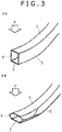
FIG. 3A illustrates a shape of a bumper reinforcement in a first half of collision. -
FIG. 3B illustrates a shape of the bumper reinforcement in a second half of collision. -
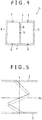
FIG. 4 is a cross section of a bumper reinforcement according to still another embodiment of the present invention. -
FIG. 5 schematically illustrates residual stress distribution along a cross-section of the bumper reinforcement subjected to large R bending. - An embodiment of a bumper reinforcement of the invention is now described with reference to
FIGS. 1A and 1B . Abumper reinforcement 1 ofFIG. 1A is formed of an aluminum alloy extrusion with a closed-section structure having welded portions along a longitudinal direction (extrusion direction). The closed-section structure includes a pair of flanges located on a vehicle body side and on a collision side (vehicle body-side flange 2 and collision-side flange 3) with a space therebetween, and a pair ofwebs flanges FIG. 1A , the pair offlanges webs - Although no projecting flange is provided on both ends of the
respective flanges bumper reinforcement 1 ofFIG. 1A , the projecting flange may be provided on one or both of the flanges in a sectional shape (for example, see Japanese Unexamined Patent Application Publication No.2003-127808 - In the
bumper reinforcement 1, weldedportions flanges welded portions bumper reinforcement 1. - The
welded portions flanges welded portions welded portions webs flanges webs webs 4 and 5 (positions at each of which a distance from theweb 4 is the same as a distance from the web 5) as shown inFIG. 1A . - An aluminum alloy extrusion with a closed-section structure as a material of the
door beam 1 is manufactured using a hollow die such as a porthole die, a bridge die, and a spider die. Thewelded portions -
FIG. 2A illustrates a sectional view of another embodiment of bumper reinforcement 11, which is different from the bumper reinforcement 1 (FIG. 1A ) according to the present disclosure. In the bumper reinforcement 11 ofFIG. 2A , substantially the same portion as that of thebumper reinforcement 1 ofFIG. 1A is designated by the same numeral. - The bumper reinforcement 11 is formed of an aluminum alloy extrusion with a closed-section structure having welded portions along the longitudinal direction (extrusion direction).
- However, the bumper reinforcement 11 is different from the
bumper reinforcement 1 in thatwelded portions webs welded portions bumper reinforcement 1, thewelded portions - When a collision load P is applied to the
bumper reinforcement 1, 11, thebumper reinforcement 1, 11 undergoes bending-deformation with a vehicle vertical direction as a rotational axis, and tensile strain occurs in the vehicle body-side flange 2 while compressive strain occurs in the collision-side flange 3 in the first half of collision (FIG. 3A ). Subsequently, in the second half of collision (FIG. 3B ), each of thewebs - The bumper reinforcement is required to have high energy absorption because it receives a collision load. To secure a high energy absorption, it is necessary to allow each web to be buckled to relieve tensile strain occurring in the flange on the vehicle body side (collision back side) so as to prevent fracture of the vehicle body-side flange particularly in the second half of collision. During buckling, the web is bending-deformed about its intermediate region in the vehicle front-back direction, and local strain concentration occurs in the region. When the web has a welded portion having a low fracture limit, the web tends to be early buckled and deformed starting from the welded portion, or the welded portion easily fractures in the second half of collision, so that energy absorption performance may be reduced thereafter.
- For the bumper reinforcement 11, the welded
portions respective webs FIG. 2B ), therefore, therespective webs portions portions - For the
bumper reinforcement 1, the weldedportions webs portions webs webs FIG. 1B ), making it possible to prevent energy absorption performance from being reduced. - In the
bumper reinforcement 1, the weldedportions portions flanges respective flanges respective webs portions entire flanges portions flanges portions portions portions -
FIG. 4 shows a sectional view of still another embodiment of the bumper reinforcement of the invention. In abumper reinforcement 21 ofFIG. 4 , substantially the same portion as that of thebumper reinforcement 1 ofFIG. 1A is designated by the same numeral. - The
bumper reinforcement 21 corresponds to thebumper reinforcement 1 in having a pair offlanges webs bumper reinforcement 1 in that amiddle rib 8 vertically connecting theflanges webs middle rib 8, weldedportions middle rib 8 and therespective webs flange 2 of thebumper reinforcement 21, weldedportions middle rib 8 and therespective webs flange 3, and a welded portion 9 is formed in themiddle rib 8. - In the
bumper reinforcement 21, no welded portion, which is to be a starting point of buckling deformation during collision, is formed in thewebs bumper reinforcement 1, early buckling and fracture of theweb bumper reinforcement 21 has a welded portion 9 in themiddle rib 8. However, when thebumper reinforcement 21 is bending-deformed during collision, since themiddle rib 8 is less likely to receive a couple of forces and thus does not tend to fall down, themiddle rib 8 predominantly undergoes in-plane deformation. In themiddle rib 8, therefore, buckling deformation starting from the welded portion 9 or occurrence of fracture of the welded portion 9 is delayed compared with the case where thewebs portions FIG. 2A ). Hence, influence of the welded portion 9 formed in the middle rib 8 (on energy absorption performance) is small compared with the weldedportions webs - The aluminum alloy extrusion is subjected to plastic working as necessary. As a result, the bumper reinforcement of the invention may have various forms in plan view. A known form in plan view may include a shape formed by bend forming of an extrusion over its entire length (so-called large R bending) so that the extrusion is convexly curved outward in the vehicle front-back direction (for example, see Japanese Unexamined Patent Application Publication No.
2010-046685 2003-285703 2015-168299 - When the bend forming is performed through simple bending, in which no tensile strength is applied in the longitudinal direction, and when the bumper reinforcement has a shape being convexly curved outward in the vehicle front-back direction, residual stress distribution in the bumper reinforcement is roughly as shown by a solid line in
FIG. 5 . Xc indicates a neutral axis of bending, and the right side of an axis Y shows tensile stress while the left side thereof shows compressive stress. The residual tensile stress is maximized at a position slightly close to the collision-side flange 3 from the neutral axis Xc. When the bend forming is performed through tensile bending, the residual stress distribution in the bumper reinforcement is roughly as shown by a broken line inFIG. 5 . The neutral axis Xc of bending is shifted toward the vehicle body-side flange 2 by tensile force, thereby the residual tensile stress is maximized at a position close to theinner flange 2 compared with the case of simple bending. In each case, large tensile stress remains in a roughly central region in a vehicle width direction of each of thewebs - In the aluminum alloy extrusion with the closed-section structure, the welded portion tends to induce stress corrosion cracking compared with any other portion (normal portion). If such a welded portion exists in the roughly central region in the vehicle width direction of the
web FIG. 1A ), the weldedportions respective webs webs portions respective webs 4 and 5 (FIG. 2A ), allowing heavier bend forming. In still another embodiment of the bumper reinforcement of the invention (FIG. 4 ), although the welded portion 9 is formed in themiddle rib 8, since thewebs middle rib 8, even if stress corrosion cracking occurs in themiddle rib 8, influence of such stress corrosion cracking is limitative. - When at least a longitudinal part of the bumper reinforcement is subjected to press working (crushing), the
webs flanges webs 4 and 5 (see Japanese Unexamined Patent Application Publication No.2014-145119 FIG. 1A ), however, since the weldedportions respective webs webs portions respective webs 4 and 5 (FIG. 2A ), allowing heavier crushing. In addition, the weldedportions respective webs FIG. 4 ), although the welded portion 9 is formed in themiddle rib 8, since thewebs middle rib 8, even if stress corrosion cracking occurs in themiddle rib 8, influence of such cracking is limitative. - While a high-strength 7000-series aluminum alloy extrusion has a lower fracture limit than a 6000-series aluminum alloy extrusion and tends to induce stress corrosion cracking, it can be preferably, but not limitedly, used as the aluminum alloy extrusion as a material of the bumper reinforcement. A composition defined in JIS or the AA standard can be used as a composition of the 7000-series aluminum alloy. A preferred composition may contain, in percent by mass, Zn: 3 to 8, Mg: 0.4 to 2.5, Cu: 0.05 to 2.0, Ti: 0.005 to 0.2, and at least one of Mn: 0.01 to 0.3, Cr: 0.01 to 0.3, and Zr: 0.01 to 0.3, with the remainder consisting of Al and impurities.
- This application claims the benefits of priority to Japanese Patent Application No.
2018-090253, filed May 8, 2018
Claims (8)
- A bumper reinforcement, comprising:an aluminum alloy extrusion body having a pair of flanges to be positioned on a vehicle body side and on a collision side and a pair of webs to be positioned in a vehicle vertical direction,wherein the pair of webs connect the pair of flanges at joint portions such that the pair of webs and the pair of flanges form a closed cross section, and the pair of webs do not have a welded portion.
- The bumper reinforcement according to claim 1, wherein each of the pair of flanges has the welded portion.
- The bumper reinforcement according to claim 2, wherein each of the pair of flanges has the welded portion between the joint portions.
- The bumper reinforcement according to any one of claims 1-3, wherein the aluminum alloy extrusion body has a middle rib connecting the pair of flanges and positioned between the pair of webs.
- The bumper reinforcement according to claim 4, wherein the middle rib has the welded portion.
- The bumper reinforcement according to claim 4, wherein each of the pair of flanges has the welded portion at a position not connected to the middle rib.
- The bumper reinforcement according to any one of claims 1-6, wherein the aluminum alloy extrusion body comprises a 7000-series aluminum alloy.
- The bumper reinforcement according to any one of claims 1-7, wherein the aluminum alloy extrusion body comprises an aluminum alloy including Al, 3-8 mass% of Zn, 0.4-2.5 mass% of Mg, 0.05 to 2.0 mass% of Cu, and 0.005 to 0.2 mass% of Ti, and further including at least one of 0.01 to 0.3 mass% of Mn, 0.01 to 0.3 mass% of Cr, and 0.01 to 0.3 mass% of Zr.
Applications Claiming Priority (1)
| Application Number | Priority Date | Filing Date | Title |
|---|---|---|---|
| JP2018090253A JP7051569B2 (en) | 2018-05-08 | 2018-05-08 | Car bumper reinforcement |
Publications (2)
| Publication Number | Publication Date |
|---|---|
| EP3566911A1 true EP3566911A1 (en) | 2019-11-13 |
| EP3566911B1 EP3566911B1 (en) | 2020-08-12 |
Family
ID=66239784
Family Applications (1)
| Application Number | Title | Priority Date | Filing Date |
|---|---|---|---|
| EP19170032.7A Not-in-force EP3566911B1 (en) | 2018-05-08 | 2019-04-18 | Bumper reinforcement |
Country Status (4)
| Country | Link |
|---|---|
| US (1) | US11318899B2 (en) |
| EP (1) | EP3566911B1 (en) |
| JP (1) | JP7051569B2 (en) |
| CN (1) | CN110450745B (en) |
Citations (15)
| Publication number | Priority date | Publication date | Assignee | Title |
|---|---|---|---|---|
| JPH07227618A (en) * | 1994-02-21 | 1995-08-29 | Kobe Steel Ltd | Al alloy extrudate having excellent bending workability |
| JPH10306338A (en) | 1997-04-28 | 1998-11-17 | Sumitomo Light Metal Ind Ltd | Al-Cu-Mg-Si alloy hollow extruded material excellent in strength and corrosion resistance and method for producing the same |
| JP2003127808A (en) | 2002-07-12 | 2003-05-08 | Kobe Steel Ltd | Reinforcement of bumper |
| JP2003154407A (en) | 2001-11-19 | 2003-05-27 | Honda Motor Co Ltd | Aluminum extruded material for hydroforming and method of manufacturing the same |
| JP2003285703A (en) | 2002-03-28 | 2003-10-07 | Kobe Steel Ltd | Bumper reinforcing member with stay |
| JP2007231408A (en) | 2006-03-03 | 2007-09-13 | Kobe Steel Ltd | Aluminum alloy hollow extruded shape material for tube expansion forming and aluminum alloy hollow member |
| JP2009045672A (en) | 2008-11-20 | 2009-03-05 | Honda Motor Co Ltd | Hydroforming process for aluminum hollow extruded material |
| JP2009197269A (en) * | 2008-02-20 | 2009-09-03 | Kobe Steel Ltd | Composite extruded material of aluminum alloy for weld structure |
| JP2010046685A (en) | 2008-08-21 | 2010-03-04 | Kobe Steel Ltd | Roll-bent member and roll bending method |
| JP2010181020A (en) * | 2009-02-09 | 2010-08-19 | Kobe Steel Ltd | Shock absorbing member |
| WO2012147179A1 (en) * | 2011-04-27 | 2012-11-01 | 日軽金アクト株式会社 | Bumper structure and bumper stay |
| JP2014145119A (en) | 2013-01-30 | 2014-08-14 | Kobe Steel Ltd | 7000 series aluminum alloy member excellent in stress corrosion crack resistance and its manufacturing method |
| JP2015168299A (en) | 2014-03-05 | 2015-09-28 | 株式会社神戸製鋼所 | Bumper beam of motor vehicle |
| US20160114747A1 (en) * | 2014-10-22 | 2016-04-28 | Kabushiki Kaisha Kobe Seiko Sho (Kobe Steel, Ltd.) | Anti-collision component |
| JP2018090253A (en) | 2018-03-23 | 2018-06-14 | 株式会社デンソー | Headlight control device |
Family Cites Families (11)
| Publication number | Priority date | Publication date | Assignee | Title |
|---|---|---|---|---|
| US5059056A (en) * | 1989-03-07 | 1991-10-22 | Aluminum Company Of America | Extrdued node |
| WO2007070731A1 (en) * | 2005-11-09 | 2007-06-21 | Alcoa Inc. | A multi-alloy monolithic extruded structural member and method of producing thereof |
| JP4311679B2 (en) * | 2006-03-22 | 2009-08-12 | 株式会社神戸製鋼所 | Manufacturing method of energy absorbing member for automobile |
| JP4562677B2 (en) * | 2006-03-30 | 2010-10-13 | 株式会社神戸製鋼所 | Welded structure closed section frame |
| JP5588170B2 (en) * | 2007-03-26 | 2014-09-10 | アイシン軽金属株式会社 | 7000 series aluminum alloy extruded material and method for producing the same |
| JP5503334B2 (en) | 2010-03-02 | 2014-05-28 | 株式会社神戸製鋼所 | Structural member |
| JP6266368B2 (en) * | 2014-02-06 | 2018-01-24 | 株式会社神戸製鋼所 | Door beam made of extruded aluminum alloy |
| US9533343B2 (en) * | 2014-06-12 | 2017-01-03 | Ford Global Technologies, Llc | Aluminum porthole extruded tubing with locating feature |
| JP6322329B1 (en) * | 2017-11-22 | 2018-05-09 | 株式会社神戸製鋼所 | Door beam |
| US10906080B2 (en) * | 2018-04-16 | 2021-02-02 | Ford Motor Company | System and methods to radially orient extruded tubing for vehicle body component |
| JP6452878B1 (en) * | 2018-04-24 | 2019-01-16 | 株式会社神戸製鋼所 | Door beam |
-
2018
- 2018-05-08 JP JP2018090253A patent/JP7051569B2/en active Active
-
2019
- 2019-02-19 CN CN201910125592.2A patent/CN110450745B/en active Active
- 2019-04-15 US US16/383,717 patent/US11318899B2/en active Active
- 2019-04-18 EP EP19170032.7A patent/EP3566911B1/en not_active Not-in-force
Patent Citations (15)
| Publication number | Priority date | Publication date | Assignee | Title |
|---|---|---|---|---|
| JPH07227618A (en) * | 1994-02-21 | 1995-08-29 | Kobe Steel Ltd | Al alloy extrudate having excellent bending workability |
| JPH10306338A (en) | 1997-04-28 | 1998-11-17 | Sumitomo Light Metal Ind Ltd | Al-Cu-Mg-Si alloy hollow extruded material excellent in strength and corrosion resistance and method for producing the same |
| JP2003154407A (en) | 2001-11-19 | 2003-05-27 | Honda Motor Co Ltd | Aluminum extruded material for hydroforming and method of manufacturing the same |
| JP2003285703A (en) | 2002-03-28 | 2003-10-07 | Kobe Steel Ltd | Bumper reinforcing member with stay |
| JP2003127808A (en) | 2002-07-12 | 2003-05-08 | Kobe Steel Ltd | Reinforcement of bumper |
| JP2007231408A (en) | 2006-03-03 | 2007-09-13 | Kobe Steel Ltd | Aluminum alloy hollow extruded shape material for tube expansion forming and aluminum alloy hollow member |
| JP2009197269A (en) * | 2008-02-20 | 2009-09-03 | Kobe Steel Ltd | Composite extruded material of aluminum alloy for weld structure |
| JP2010046685A (en) | 2008-08-21 | 2010-03-04 | Kobe Steel Ltd | Roll-bent member and roll bending method |
| JP2009045672A (en) | 2008-11-20 | 2009-03-05 | Honda Motor Co Ltd | Hydroforming process for aluminum hollow extruded material |
| JP2010181020A (en) * | 2009-02-09 | 2010-08-19 | Kobe Steel Ltd | Shock absorbing member |
| WO2012147179A1 (en) * | 2011-04-27 | 2012-11-01 | 日軽金アクト株式会社 | Bumper structure and bumper stay |
| JP2014145119A (en) | 2013-01-30 | 2014-08-14 | Kobe Steel Ltd | 7000 series aluminum alloy member excellent in stress corrosion crack resistance and its manufacturing method |
| JP2015168299A (en) | 2014-03-05 | 2015-09-28 | 株式会社神戸製鋼所 | Bumper beam of motor vehicle |
| US20160114747A1 (en) * | 2014-10-22 | 2016-04-28 | Kabushiki Kaisha Kobe Seiko Sho (Kobe Steel, Ltd.) | Anti-collision component |
| JP2018090253A (en) | 2018-03-23 | 2018-06-14 | 株式会社デンソー | Headlight control device |
Also Published As
| Publication number | Publication date |
|---|---|
| EP3566911B1 (en) | 2020-08-12 |
| US11318899B2 (en) | 2022-05-03 |
| JP7051569B2 (en) | 2022-04-11 |
| CN110450745A (en) | 2019-11-15 |
| US20190344736A1 (en) | 2019-11-14 |
| CN110450745B (en) | 2023-01-10 |
| JP2019196063A (en) | 2019-11-14 |
Similar Documents
| Publication | Publication Date | Title |
|---|---|---|
| US10814368B2 (en) | Door beam | |
| US11279408B2 (en) | Hollow member | |
| EP3670272B1 (en) | Bumper beam and vehicle | |
| JP6588972B2 (en) | Reinforcing elements for automobiles, methods for manufacturing reinforcing elements and door assemblies | |
| US10843537B2 (en) | Door beam | |
| JP2015147490A (en) | Door beam made of aluminum alloy extruded material | |
| US11318899B2 (en) | Bumper reinforcement | |
| JP7187120B2 (en) | Aluminum alloy door beam | |
| US11491525B2 (en) | Aluminum alloy component | |
| JP2019166855A (en) | Vehicular structural member and vehicle | |
| JPH09207566A (en) | Reinforcing pipe for automobile door |
Legal Events
| Date | Code | Title | Description |
|---|---|---|---|
| PUAI | Public reference made under article 153(3) epc to a published international application that has entered the european phase |
Free format text: ORIGINAL CODE: 0009012 |
|
| STAA | Information on the status of an ep patent application or granted ep patent |
Free format text: STATUS: THE APPLICATION HAS BEEN PUBLISHED |
|
| AK | Designated contracting states |
Kind code of ref document: A1 Designated state(s): AL AT BE BG CH CY CZ DE DK EE ES FI FR GB GR HR HU IE IS IT LI LT LU LV MC MK MT NL NO PL PT RO RS SE SI SK SM TR |
|
| AX | Request for extension of the european patent |
Extension state: BA ME |
|
| STAA | Information on the status of an ep patent application or granted ep patent |
Free format text: STATUS: REQUEST FOR EXAMINATION WAS MADE |
|
| GRAP | Despatch of communication of intention to grant a patent |
Free format text: ORIGINAL CODE: EPIDOSNIGR1 |
|
| STAA | Information on the status of an ep patent application or granted ep patent |
Free format text: STATUS: GRANT OF PATENT IS INTENDED |
|
| 17P | Request for examination filed |
Effective date: 20200213 |
|
| RBV | Designated contracting states (corrected) |
Designated state(s): AL AT BE BG CH CY CZ DE DK EE ES FI FR GB GR HR HU IE IS IT LI LT LU LV MC MK MT NL NO PL PT RO RS SE SI SK SM TR |
|
| RIC1 | Information provided on ipc code assigned before grant |
Ipc: B60R 19/18 20060101AFI20200224BHEP |
|
| INTG | Intention to grant announced |
Effective date: 20200323 |
|
| RIN1 | Information on inventor provided before grant (corrected) |
Inventor name: MORITA, SHINYA Inventor name: HASHIMOTO, NARIKAZU |
|
| GRAS | Grant fee paid |
Free format text: ORIGINAL CODE: EPIDOSNIGR3 |
|
| GRAA | (expected) grant |
Free format text: ORIGINAL CODE: 0009210 |
|
| STAA | Information on the status of an ep patent application or granted ep patent |
Free format text: STATUS: THE PATENT HAS BEEN GRANTED |
|
| AK | Designated contracting states |
Kind code of ref document: B1 Designated state(s): AL AT BE BG CH CY CZ DE DK EE ES FI FR GB GR HR HU IE IS IT LI LT LU LV MC MK MT NL NO PL PT RO RS SE SI SK SM TR |
|
| REG | Reference to a national code |
Ref country code: CH Ref legal event code: EP |
|
| REG | Reference to a national code |
Ref country code: DE Ref legal event code: R096 Ref document number: 602019000453 Country of ref document: DE |
|
| REG | Reference to a national code |
Ref country code: IE Ref legal event code: FG4D |
|
| REG | Reference to a national code |
Ref country code: AT Ref legal event code: REF Ref document number: 1301251 Country of ref document: AT Kind code of ref document: T Effective date: 20200915 |
|
| REG | Reference to a national code |
Ref country code: LT Ref legal event code: MG4D |
|
| REG | Reference to a national code |
Ref country code: NL Ref legal event code: MP Effective date: 20200812 |
|
| PG25 | Lapsed in a contracting state [announced via postgrant information from national office to epo] |
Ref country code: GR Free format text: LAPSE BECAUSE OF FAILURE TO SUBMIT A TRANSLATION OF THE DESCRIPTION OR TO PAY THE FEE WITHIN THE PRESCRIBED TIME-LIMIT Effective date: 20201113 Ref country code: FI Free format text: LAPSE BECAUSE OF FAILURE TO SUBMIT A TRANSLATION OF THE DESCRIPTION OR TO PAY THE FEE WITHIN THE PRESCRIBED TIME-LIMIT Effective date: 20200812 Ref country code: NO Free format text: LAPSE BECAUSE OF FAILURE TO SUBMIT A TRANSLATION OF THE DESCRIPTION OR TO PAY THE FEE WITHIN THE PRESCRIBED TIME-LIMIT Effective date: 20201112 Ref country code: HR Free format text: LAPSE BECAUSE OF FAILURE TO SUBMIT A TRANSLATION OF THE DESCRIPTION OR TO PAY THE FEE WITHIN THE PRESCRIBED TIME-LIMIT Effective date: 20200812 Ref country code: LT Free format text: LAPSE BECAUSE OF FAILURE TO SUBMIT A TRANSLATION OF THE DESCRIPTION OR TO PAY THE FEE WITHIN THE PRESCRIBED TIME-LIMIT Effective date: 20200812 Ref country code: SE Free format text: LAPSE BECAUSE OF FAILURE TO SUBMIT A TRANSLATION OF THE DESCRIPTION OR TO PAY THE FEE WITHIN THE PRESCRIBED TIME-LIMIT Effective date: 20200812 Ref country code: BG Free format text: LAPSE BECAUSE OF FAILURE TO SUBMIT A TRANSLATION OF THE DESCRIPTION OR TO PAY THE FEE WITHIN THE PRESCRIBED TIME-LIMIT Effective date: 20201112 |
|
| REG | Reference to a national code |
Ref country code: AT Ref legal event code: MK05 Ref document number: 1301251 Country of ref document: AT Kind code of ref document: T Effective date: 20200812 |
|
| PG25 | Lapsed in a contracting state [announced via postgrant information from national office to epo] |
Ref country code: PL Free format text: LAPSE BECAUSE OF FAILURE TO SUBMIT A TRANSLATION OF THE DESCRIPTION OR TO PAY THE FEE WITHIN THE PRESCRIBED TIME-LIMIT Effective date: 20200812 Ref country code: NL Free format text: LAPSE BECAUSE OF FAILURE TO SUBMIT A TRANSLATION OF THE DESCRIPTION OR TO PAY THE FEE WITHIN THE PRESCRIBED TIME-LIMIT Effective date: 20200812 Ref country code: RS Free format text: LAPSE BECAUSE OF FAILURE TO SUBMIT A TRANSLATION OF THE DESCRIPTION OR TO PAY THE FEE WITHIN THE PRESCRIBED TIME-LIMIT Effective date: 20200812 Ref country code: LV Free format text: LAPSE BECAUSE OF FAILURE TO SUBMIT A TRANSLATION OF THE DESCRIPTION OR TO PAY THE FEE WITHIN THE PRESCRIBED TIME-LIMIT Effective date: 20200812 Ref country code: IS Free format text: LAPSE BECAUSE OF FAILURE TO SUBMIT A TRANSLATION OF THE DESCRIPTION OR TO PAY THE FEE WITHIN THE PRESCRIBED TIME-LIMIT Effective date: 20201212 |
|
| PG25 | Lapsed in a contracting state [announced via postgrant information from national office to epo] |
Ref country code: SM Free format text: LAPSE BECAUSE OF FAILURE TO SUBMIT A TRANSLATION OF THE DESCRIPTION OR TO PAY THE FEE WITHIN THE PRESCRIBED TIME-LIMIT Effective date: 20200812 Ref country code: RO Free format text: LAPSE BECAUSE OF FAILURE TO SUBMIT A TRANSLATION OF THE DESCRIPTION OR TO PAY THE FEE WITHIN THE PRESCRIBED TIME-LIMIT Effective date: 20200812 Ref country code: CZ Free format text: LAPSE BECAUSE OF FAILURE TO SUBMIT A TRANSLATION OF THE DESCRIPTION OR TO PAY THE FEE WITHIN THE PRESCRIBED TIME-LIMIT Effective date: 20200812 Ref country code: DK Free format text: LAPSE BECAUSE OF FAILURE TO SUBMIT A TRANSLATION OF THE DESCRIPTION OR TO PAY THE FEE WITHIN THE PRESCRIBED TIME-LIMIT Effective date: 20200812 Ref country code: EE Free format text: LAPSE BECAUSE OF FAILURE TO SUBMIT A TRANSLATION OF THE DESCRIPTION OR TO PAY THE FEE WITHIN THE PRESCRIBED TIME-LIMIT Effective date: 20200812 |
|
| REG | Reference to a national code |
Ref country code: DE Ref legal event code: R097 Ref document number: 602019000453 Country of ref document: DE |
|
| PG25 | Lapsed in a contracting state [announced via postgrant information from national office to epo] |
Ref country code: ES Free format text: LAPSE BECAUSE OF FAILURE TO SUBMIT A TRANSLATION OF THE DESCRIPTION OR TO PAY THE FEE WITHIN THE PRESCRIBED TIME-LIMIT Effective date: 20200812 Ref country code: AT Free format text: LAPSE BECAUSE OF FAILURE TO SUBMIT A TRANSLATION OF THE DESCRIPTION OR TO PAY THE FEE WITHIN THE PRESCRIBED TIME-LIMIT Effective date: 20200812 Ref country code: AL Free format text: LAPSE BECAUSE OF FAILURE TO SUBMIT A TRANSLATION OF THE DESCRIPTION OR TO PAY THE FEE WITHIN THE PRESCRIBED TIME-LIMIT Effective date: 20200812 |
|
| PLBE | No opposition filed within time limit |
Free format text: ORIGINAL CODE: 0009261 |
|
| STAA | Information on the status of an ep patent application or granted ep patent |
Free format text: STATUS: NO OPPOSITION FILED WITHIN TIME LIMIT |
|
| PG25 | Lapsed in a contracting state [announced via postgrant information from national office to epo] |
Ref country code: SK Free format text: LAPSE BECAUSE OF FAILURE TO SUBMIT A TRANSLATION OF THE DESCRIPTION OR TO PAY THE FEE WITHIN THE PRESCRIBED TIME-LIMIT Effective date: 20200812 |
|
| 26N | No opposition filed |
Effective date: 20210514 |
|
| PG25 | Lapsed in a contracting state [announced via postgrant information from national office to epo] |
Ref country code: IT Free format text: LAPSE BECAUSE OF FAILURE TO SUBMIT A TRANSLATION OF THE DESCRIPTION OR TO PAY THE FEE WITHIN THE PRESCRIBED TIME-LIMIT Effective date: 20200812 |
|
| PG25 | Lapsed in a contracting state [announced via postgrant information from national office to epo] |
Ref country code: MC Free format text: LAPSE BECAUSE OF FAILURE TO SUBMIT A TRANSLATION OF THE DESCRIPTION OR TO PAY THE FEE WITHIN THE PRESCRIBED TIME-LIMIT Effective date: 20200812 |
|
| PG25 | Lapsed in a contracting state [announced via postgrant information from national office to epo] |
Ref country code: LU Free format text: LAPSE BECAUSE OF NON-PAYMENT OF DUE FEES Effective date: 20210418 |
|
| REG | Reference to a national code |
Ref country code: BE Ref legal event code: MM Effective date: 20210430 |
|
| PG25 | Lapsed in a contracting state [announced via postgrant information from national office to epo] |
Ref country code: FR Free format text: LAPSE BECAUSE OF NON-PAYMENT OF DUE FEES Effective date: 20210430 |
|
| PG25 | Lapsed in a contracting state [announced via postgrant information from national office to epo] |
Ref country code: IE Free format text: LAPSE BECAUSE OF NON-PAYMENT OF DUE FEES Effective date: 20210418 |
|
| PG25 | Lapsed in a contracting state [announced via postgrant information from national office to epo] |
Ref country code: IS Free format text: LAPSE BECAUSE OF FAILURE TO SUBMIT A TRANSLATION OF THE DESCRIPTION OR TO PAY THE FEE WITHIN THE PRESCRIBED TIME-LIMIT Effective date: 20201212 |
|
| PG25 | Lapsed in a contracting state [announced via postgrant information from national office to epo] |
Ref country code: BE Free format text: LAPSE BECAUSE OF NON-PAYMENT OF DUE FEES Effective date: 20210430 |
|
| REG | Reference to a national code |
Ref country code: CH Ref legal event code: PL |
|
| PG25 | Lapsed in a contracting state [announced via postgrant information from national office to epo] |
Ref country code: LI Free format text: LAPSE BECAUSE OF NON-PAYMENT OF DUE FEES Effective date: 20220430 Ref country code: CH Free format text: LAPSE BECAUSE OF NON-PAYMENT OF DUE FEES Effective date: 20220430 |
|
| PG25 | Lapsed in a contracting state [announced via postgrant information from national office to epo] |
Ref country code: PT Free format text: LAPSE BECAUSE OF FAILURE TO SUBMIT A TRANSLATION OF THE DESCRIPTION OR TO PAY THE FEE WITHIN THE PRESCRIBED TIME-LIMIT Effective date: 20201214 |
|
| P01 | Opt-out of the competence of the unified patent court (upc) registered |
Effective date: 20230523 |
|
| PG25 | Lapsed in a contracting state [announced via postgrant information from national office to epo] |
Ref country code: CY Free format text: LAPSE BECAUSE OF FAILURE TO SUBMIT A TRANSLATION OF THE DESCRIPTION OR TO PAY THE FEE WITHIN THE PRESCRIBED TIME-LIMIT Effective date: 20200812 |
|
| PG25 | Lapsed in a contracting state [announced via postgrant information from national office to epo] |
Ref country code: HU Free format text: LAPSE BECAUSE OF FAILURE TO SUBMIT A TRANSLATION OF THE DESCRIPTION OR TO PAY THE FEE WITHIN THE PRESCRIBED TIME-LIMIT; INVALID AB INITIO Effective date: 20190418 |
|
| PGFP | Annual fee paid to national office [announced via postgrant information from national office to epo] |
Ref country code: DE Payment date: 20230228 Year of fee payment: 5 |
|
| PG25 | Lapsed in a contracting state [announced via postgrant information from national office to epo] |
Ref country code: SI Free format text: LAPSE BECAUSE OF FAILURE TO SUBMIT A TRANSLATION OF THE DESCRIPTION OR TO PAY THE FEE WITHIN THE PRESCRIBED TIME-LIMIT Effective date: 20200812 |
|
| GBPC | Gb: european patent ceased through non-payment of renewal fee |
Effective date: 20230418 |
|
| PG25 | Lapsed in a contracting state [announced via postgrant information from national office to epo] |
Ref country code: GB Free format text: LAPSE BECAUSE OF NON-PAYMENT OF DUE FEES Effective date: 20230418 |
|
| PG25 | Lapsed in a contracting state [announced via postgrant information from national office to epo] |
Ref country code: GB Free format text: LAPSE BECAUSE OF NON-PAYMENT OF DUE FEES Effective date: 20230418 |
|
| PG25 | Lapsed in a contracting state [announced via postgrant information from national office to epo] |
Ref country code: MK Free format text: LAPSE BECAUSE OF FAILURE TO SUBMIT A TRANSLATION OF THE DESCRIPTION OR TO PAY THE FEE WITHIN THE PRESCRIBED TIME-LIMIT Effective date: 20200812 |
|
| PG25 | Lapsed in a contracting state [announced via postgrant information from national office to epo] |
Ref country code: MT Free format text: LAPSE BECAUSE OF FAILURE TO SUBMIT A TRANSLATION OF THE DESCRIPTION OR TO PAY THE FEE WITHIN THE PRESCRIBED TIME-LIMIT Effective date: 20200812 |
|
| REG | Reference to a national code |
Ref country code: DE Ref legal event code: R119 Ref document number: 602019000453 Country of ref document: DE |
|
| PG25 | Lapsed in a contracting state [announced via postgrant information from national office to epo] |
Ref country code: DE Free format text: LAPSE BECAUSE OF NON-PAYMENT OF DUE FEES Effective date: 20241105 |
|
| PG25 | Lapsed in a contracting state [announced via postgrant information from national office to epo] |
Ref country code: DE Free format text: LAPSE BECAUSE OF NON-PAYMENT OF DUE FEES Effective date: 20241105 |
|
| PG25 | Lapsed in a contracting state [announced via postgrant information from national office to epo] |
Ref country code: TR Free format text: LAPSE BECAUSE OF FAILURE TO SUBMIT A TRANSLATION OF THE DESCRIPTION OR TO PAY THE FEE WITHIN THE PRESCRIBED TIME-LIMIT Effective date: 20200812 |