EP3566874A1 - Fluidic ejection cartridge and fluid ejection device thereof - Google Patents
Fluidic ejection cartridge and fluid ejection device thereof Download PDFInfo
- Publication number
- EP3566874A1 EP3566874A1 EP19166949.8A EP19166949A EP3566874A1 EP 3566874 A1 EP3566874 A1 EP 3566874A1 EP 19166949 A EP19166949 A EP 19166949A EP 3566874 A1 EP3566874 A1 EP 3566874A1
- Authority
- EP
- European Patent Office
- Prior art keywords
- cartridge
- removable tape
- fluidic
- ejection
- peel strength
- Prior art date
- Legal status (The legal status is an assumption and is not a legal conclusion. Google has not performed a legal analysis and makes no representation as to the accuracy of the status listed.)
- Granted
Links
Images



Classifications
-
- B—PERFORMING OPERATIONS; TRANSPORTING
- B05—SPRAYING OR ATOMISING IN GENERAL; APPLYING FLUENT MATERIALS TO SURFACES, IN GENERAL
- B05B—SPRAYING APPARATUS; ATOMISING APPARATUS; NOZZLES
- B05B15/00—Details of spraying plant or spraying apparatus not otherwise provided for; Accessories
- B05B15/14—Arrangements for preventing or controlling structural damage to spraying apparatus or its outlets, e.g. for breaking at desired places; Arrangements for handling or replacing damaged parts
- B05B15/16—Arrangements for preventing or controlling structural damage to spraying apparatus or its outlets, e.g. for breaking at desired places; Arrangements for handling or replacing damaged parts for preventing non-intended contact between spray heads or nozzles and foreign bodies, e.g. nozzle guards
-
- B—PERFORMING OPERATIONS; TRANSPORTING
- B41—PRINTING; LINING MACHINES; TYPEWRITERS; STAMPS
- B41J—TYPEWRITERS; SELECTIVE PRINTING MECHANISMS, i.e. MECHANISMS PRINTING OTHERWISE THAN FROM A FORME; CORRECTION OF TYPOGRAPHICAL ERRORS
- B41J2/00—Typewriters or selective printing mechanisms characterised by the printing or marking process for which they are designed
- B41J2/005—Typewriters or selective printing mechanisms characterised by the printing or marking process for which they are designed characterised by bringing liquid or particles selectively into contact with a printing material
- B41J2/01—Ink jet
- B41J2/17—Ink jet characterised by ink handling
- B41J2/175—Ink supply systems ; Circuit parts therefor
- B41J2/17503—Ink cartridges
-
- B—PERFORMING OPERATIONS; TRANSPORTING
- B41—PRINTING; LINING MACHINES; TYPEWRITERS; STAMPS
- B41J—TYPEWRITERS; SELECTIVE PRINTING MECHANISMS, i.e. MECHANISMS PRINTING OTHERWISE THAN FROM A FORME; CORRECTION OF TYPOGRAPHICAL ERRORS
- B41J2/00—Typewriters or selective printing mechanisms characterised by the printing or marking process for which they are designed
- B41J2/005—Typewriters or selective printing mechanisms characterised by the printing or marking process for which they are designed characterised by bringing liquid or particles selectively into contact with a printing material
- B41J2/01—Ink jet
- B41J2/17—Ink jet characterised by ink handling
- B41J2/175—Ink supply systems ; Circuit parts therefor
- B41J2/17503—Ink cartridges
- B41J2/17536—Protection of cartridges or parts thereof, e.g. tape
-
- B—PERFORMING OPERATIONS; TRANSPORTING
- B05—SPRAYING OR ATOMISING IN GENERAL; APPLYING FLUENT MATERIALS TO SURFACES, IN GENERAL
- B05B—SPRAYING APPARATUS; ATOMISING APPARATUS; NOZZLES
- B05B15/00—Details of spraying plant or spraying apparatus not otherwise provided for; Accessories
- B05B15/50—Arrangements for cleaning; Arrangements for preventing deposits, drying-out or blockage; Arrangements for detecting improper discharge caused by the presence of foreign matter
-
- B—PERFORMING OPERATIONS; TRANSPORTING
- B41—PRINTING; LINING MACHINES; TYPEWRITERS; STAMPS
- B41J—TYPEWRITERS; SELECTIVE PRINTING MECHANISMS, i.e. MECHANISMS PRINTING OTHERWISE THAN FROM A FORME; CORRECTION OF TYPOGRAPHICAL ERRORS
- B41J2/00—Typewriters or selective printing mechanisms characterised by the printing or marking process for which they are designed
- B41J2/005—Typewriters or selective printing mechanisms characterised by the printing or marking process for which they are designed characterised by bringing liquid or particles selectively into contact with a printing material
- B41J2/01—Ink jet
- B41J2/17—Ink jet characterised by ink handling
- B41J2/175—Ink supply systems ; Circuit parts therefor
- B41J2/17503—Ink cartridges
- B41J2/17526—Electrical contacts to the cartridge
- B41J2/1753—Details of contacts on the cartridge, e.g. protection of contacts
-
- B—PERFORMING OPERATIONS; TRANSPORTING
- B41—PRINTING; LINING MACHINES; TYPEWRITERS; STAMPS
- B41J—TYPEWRITERS; SELECTIVE PRINTING MECHANISMS, i.e. MECHANISMS PRINTING OTHERWISE THAN FROM A FORME; CORRECTION OF TYPOGRAPHICAL ERRORS
- B41J2/00—Typewriters or selective printing mechanisms characterised by the printing or marking process for which they are designed
- B41J2/005—Typewriters or selective printing mechanisms characterised by the printing or marking process for which they are designed characterised by bringing liquid or particles selectively into contact with a printing material
- B41J2/01—Ink jet
- B41J2/17—Ink jet characterised by ink handling
- B41J2/175—Ink supply systems ; Circuit parts therefor
- B41J2/17503—Ink cartridges
- B41J2/17553—Outer structure
Definitions
- This disclosure relates to the field of fluidic ejection cartridges and a fluid ejection device thereof. More particularly, this disclosure relates to a fluidic ejection cartridge structure for improved protective tape removal therefrom.
- Fluidic ejection cartridges may be used in variety of applications, including for instance inkjet printing applications, medicinal fluid delivery applications, and vapor delivery applications.
- the amount of time such cartridges remain in transit from the manufacture and/or in storage (prior to installation and use) may constitute a large portion of the lifecycle of the cartridge.
- the shipping and storage time may even constitute the majority of the lifecycle of the cartridge. Consequently, it is important that the operability of the cartridge not degrade during storage, even if the cartridge remains in storage for an extended period of time.
- a protective tape may be used to cover the ejection head and ejection nozzles on the ejection head.
- the protective tape prevents contamination of the ejection head, prevents seepage of fluid from the ejection head, and reduces the amount of moisture evaporated from the fluid in the cartridge during shipping and storage of the cartridge.
- the protective tape Prior to use, the protective tape must be removed from the fluidic ejection cartridge to expose the ejection nozzles. However, removal of the protective tape may itself prove to be problematic and lead to damage of the ejection head or residual tape or adhesive left on the ejection head which can hamper the operation of the fluid ejection device.
- a protective tape having a relatively weak adhesive layer is sometimes used.
- a protective tape is excessively weak in adhesiveness, it is possible that the protective tape will peel and fall off of the ejection head when the fluidic cartridge is clamped to be conveyed or packaged using automatic packaging machines. Excessive vibrations of the fluidic cartridge during packaging and conveying may also cause the protective tape to peel from the ejection head. Accordingly, the use of relatively weak adhesiveness of the protective tape may result in premature peeling of the tape from the ejection head.
- a protective tape having greater adhesiveness is typically used in combination with a pull tape.
- the pull tape assists in removal of the protective tape and may be attached to an underside or to a backside of the protective tape.
- the pull tape typically contains an adhesive having a substantially greater peel strength than the protective tape.
- the adhesiveness of the protective tape is great enough to prevent premature peeling from the ejection head, there is a greater possibility that the protective tape will detach from a pull tape used to remove the protective tape and thus remain on the ejection head preventing the ejection head from proper operation.
- a fluidic ejection cartridge that substantially eliminates incomplete removal of the protective tape from an ejection head. It is also desirable to ensure that the protective tape is removed from the ejection head prior to usage of the cartridge and that removal of the protective tape does not damage the ejection head.
- an embodiment of the disclosure provides a fluidic ejection cartridge and a fluidic ejection device thereof.
- the fluidic ejection cartridge includes a cartridge body for fluid having a first end and a second end opposite to the first end, and having a plurality of side walls attached to the first end and the second end; an ejection head disposed on the second end of the cartridge body; a release structure configured on one of the side walls; a first removable tape attached to the release structure on the side wall and attached to the ejection head by a first adhesive having a first peel strength, and a second removable tape attached to a portion of the first removable tape by a second adhesive having a second peel strength, wherein the second peel strength is greater than the first peel strength.
- the disclosure provides a fluidic ejection device.
- the fluidic ejection device includes the above fluidic ejection cartridge.
- An advantage of the embodiments of the disclosure is that the fluidic ejection cartridge and the fluid ejection device thereof is effective to completely remove the protective tape from the ejection head while using a protective tape that has sufficient peel strength to prevent premature peeling of the protective tape from the ejection head.
- the embodiments also enable the use of a pull tape that can effectively remove the protective tape from the ejection head without delaminating from the protective tape.
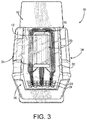
- a fluidic ejection cartridge 10 is illustrated in FIGS. 1-3 showing a first removable tape 12 and a second removable tape 14 overlapping a portion 16 of the first removable tape 12.
- the first removable tape 12 is applied to a nozzle plate 18 of an ejection head 20 for the fluidic ejection cartridge 10.
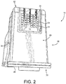
- a flexible circuit 22 is provided for the ejection head 20 and is folded over to a first end wall 26 of the fluidic ejection cartridge 10. As shown in FIG. 2 , the flexible circuit 22 contains a plurality of contacts 24 for making electrical connection between a fluid ejection device containing the fluidic ejection cartridge 10 and the ejection head 20 for controlling fluid ejection from the ejection head 20.
- a cover 28 is provided on a first end 30 of the fluidic ejection cartridge 10, wherein the cover 28 is opposite a second end 32 of the cartridge 10 containing the ejection head 20.
- the cover 28 is attached to a first side wall 34 and a second side wall 38.
- a second end wall 40 opposite the first end wall 26 is attached to the side walls 34 and 38 and the cover 28 and provides a closed container for fluid in the fluidic ejection cartridge 10.
- the ejection head 20 includes a semiconductor substrate 42 to which the flexible circuit 22 is electrically attached and the nozzle plate 18 attached to the semiconductor substrate 42 in a window (not shown) of the flexible circuit 22.
- the fluidic ejection cartridge 10 is filled with an open cell foam material 46 that holds fluid to be ejected from the ejection head 20.
- the first removable tape 12 is used to cover and protect nozzle holes on the nozzle plate 18 as described above.
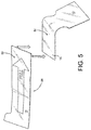
- the first removable tape 12 is shown in FIGS. 5 and 6 and is typically a blue tape 12 having an overall thickness of from about 60 to 80 microns.
- the first removable tape 12 has a base film layer 50 of polyvinyl chloride having a thickness of from about 50 to about 70 microns and an acrylic adhesive layer 52 on one side thereof having a thickness of from about 5 to about 15 microns.
- the acrylic adhesive layer 52 has a peel strength ranging from about 40 to about 80 Newton per meter (N/m) on a silicon wafer as determined using a 20-millimeter-wide sample at a peeling speed of 300 mm/min and at an angle of 90 degrees. It is important that removable tape 12 contain a low amount of impurities since it is in intimate contact with the nozzle plate 18 and could contaminate the nozzle holes in the nozzle plate 18 thereby blocking the nozzle holes from functioning properly.
- the second removable tape 14 is attached in the overlap area 16 to a backside 54 of the first removable tape 12.
- the second removable tape 14 can be made of a wide variety of materials, provided the adhesive used on an underside 56 of the second removable tape 14 having a peel strength of about 2 times greater and desirably at least about 3 time greater than the peel strength of the first removable tape 12.
- the second removable tape 14 has a peel strength of greater than about 120 N/m, such as greater than about 140 N/m, and desirably greater than about 200 N/m.
- the second removable tape 14 is also attached to the first side wall 34 of the cartridge 10 adjacent to the first removable tape 12.
- the ejection head 20 with its semiconductor substrate 42 and nozzle plate 18 is a precisely manufactured device that is capable of high resolution fluid ejection. Accordingly, protection of the ejection head 20 is important for the proper operation of the fluid ejection device.
- the first removable tape 12 is applied to the ejection head 20 and the first side wall 34 of the fluidic ejection cartridge 10 and the second removable tape 14 is applied to the first side wall 34 of the fluidic ejection cartridge 10 adjacent an end of the first removable tape 12.
- the first removable tape 12 may be peeled from the ejection head 20 in a direction that is orthogonal to a longitudinal direction of the nozzle plate 18 and substrate 42.
- Such peeling direction is effective to reduce stresses that may occur to the ejection head 20 when the first removable tape 12 is peeled therefrom and reduces the likelihood that the nozzle plate 18 will delaminate from the substrate 42. Accordingly, it is desirable that the first removable tape 12 be peeled in the orthogonal direction rather than in a longitudinal direction with respect to the ejection head 20.
- the second removable tape 14 overlap the backside 54 of the first removable tape 12 so that a release structure 60, described below, may be used to improve the removal of the first removable tape 12 from the cartridge 10. Also, since the first removable tape 12 has a lower peel strength than the second removable tape 14, overlapping the first removable tape 12 on a backside 58 of the second removable tape 14, may lead to separation of the first removable tape 12 from the second removable tape 14 and thus incomplete removal of the first removable tape 12 from the ejection head 20.
- the release structure 60 is provided on a portion of the first side wall 34 underlying the first removable tape 12 so that the first removable tape 12 will be released from the side wall 34 without separating from the second removable tape 14.
- the release structure 60 may be scored portion of the first side wall 34.
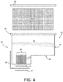
- the scored portion providing the release structure 60 may be a plurality of spaced-apart bull-nose ribs 62 as shown in FIG. 4 .
- the ribs 62 may have a score depth between adjacent ribs ranging from about 40 to about 200 microns, such as from about 50 to about 190 microns, or from about 60 to about 180 microns in depth, a spacing of the valley between adjacent ribs ranging from about 20 to about 900 microns, such as from about 40 to 700 microns, or from about 80 to about 300 microns, and a rib width ranging from about 100 to about 600 microns, such as from about 200 to about 500 microns, or from about 250 to about 400 microns.
- the spaced-apart bull-nose ribs 62 may be molded into the first side wall 34 of the cartridge 10 or may be machined into the first side wall 34 after the cartridge 10 is made. Other patterns such as dimples or cross-hatched areas may be used to provide a reduced surface area from adhesive bonding between the acrylic adhesive and the first side wall 34 of the cartridge 10. Accordingly, the adhesive layer 52 of the first removable tape 12 may be only attached to peaks 64 of the ribs 62 rather than to the first side wall 34 in a valley 66 between the ribs 62 ( FIG. 6 ) thereby reducing the area of adhesive bonding between the first removable tape 12 and the side wall 34.
- the first removable tape 12 was applied to a smooth side walls of cartridges and to ribbed side wall of cartridges and the peel strength was measured after 1 day, two weeks and four weeks.
- the ribs had a depth of 132 microns and a valley spacing between adjacent ribs of 210 microns and a rib width of 390 microns.
- the peel speed was 50 mm/min and the peel angle was 90 degrees.
- the peel strength is shown in the following table. TABLE Sample No.
- the peel strength of the first removable tape 12 on a smooth side of the cartridge 10 is about 30 to about 90 times greater than the peel strength of the first removable tape applied to the ribbed area of the cartridge 10.
- the ribbed or scored area (release structure 60) of the first side wall 34 dramatically reduced the peel strength of the first removable tape 12 so that the first removable tape 12 was easily released from the first side wall 34 without separating from the second removable tape 14.
- fluidic ejection cartridges 10 may be used in variety of applications, including for instance inkjet printing applications. Fluidic ejection cartridges may also be used for other nonprinting applications as well, particularly for applications calling for the precise metering of small amounts of liquid materials and vaporous materials.
- the ejection cartridges described herein may be used in the preparation of cosmetics, paints, or lubricants and in the ejection of liquids and vapors for medical treatment.
Landscapes
- Ink Jet (AREA)
- Adhesive Tapes (AREA)
- Coating Apparatus (AREA)
Abstract
Description
- This disclosure relates to the field of fluidic ejection cartridges and a fluid ejection device thereof. More particularly, this disclosure relates to a fluidic ejection cartridge structure for improved protective tape removal therefrom.
- Fluidic ejection cartridges may be used in variety of applications, including for instance inkjet printing applications, medicinal fluid delivery applications, and vapor delivery applications. The amount of time such cartridges remain in transit from the manufacture and/or in storage (prior to installation and use) may constitute a large portion of the lifecycle of the cartridge. In some instances, the shipping and storage time may even constitute the majority of the lifecycle of the cartridge. Consequently, it is important that the operability of the cartridge not degrade during storage, even if the cartridge remains in storage for an extended period of time.
- During shipping and storage of the fluidic ejection cartridges, a protective tape may be used to cover the ejection head and ejection nozzles on the ejection head. The protective tape prevents contamination of the ejection head, prevents seepage of fluid from the ejection head, and reduces the amount of moisture evaporated from the fluid in the cartridge during shipping and storage of the cartridge. Prior to use, the protective tape must be removed from the fluidic ejection cartridge to expose the ejection nozzles. However, removal of the protective tape may itself prove to be problematic and lead to damage of the ejection head or residual tape or adhesive left on the ejection head which can hamper the operation of the fluid ejection device.
- In order to prevent damage to the ejection head, a protective tape having a relatively weak adhesive layer is sometimes used. However, if a protective tape is excessively weak in adhesiveness, it is possible that the protective tape will peel and fall off of the ejection head when the fluidic cartridge is clamped to be conveyed or packaged using automatic packaging machines. Excessive vibrations of the fluidic cartridge during packaging and conveying may also cause the protective tape to peel from the ejection head. Accordingly, the use of relatively weak adhesiveness of the protective tape may result in premature peeling of the tape from the ejection head.
- In order to assure that the protective tape does not prematurely peel off of the ejection head, a protective tape having greater adhesiveness is typically used in combination with a pull tape. The pull tape assists in removal of the protective tape and may be attached to an underside or to a backside of the protective tape. The pull tape typically contains an adhesive having a substantially greater peel strength than the protective tape. However, if the adhesiveness of the protective tape is great enough to prevent premature peeling from the ejection head, there is a greater possibility that the protective tape will detach from a pull tape used to remove the protective tape and thus remain on the ejection head preventing the ejection head from proper operation.
- Accordingly, what is needed is a fluidic ejection cartridge that substantially eliminates incomplete removal of the protective tape from an ejection head. It is also desirable to ensure that the protective tape is removed from the ejection head prior to usage of the cartridge and that removal of the protective tape does not damage the ejection head.
- With regard to the foregoing, an embodiment of the disclosure provides a fluidic ejection cartridge and a fluidic ejection device thereof. The fluidic ejection cartridge includes a cartridge body for fluid having a first end and a second end opposite to the first end, and having a plurality of side walls attached to the first end and the second end; an ejection head disposed on the second end of the cartridge body; a release structure configured on one of the side walls; a first removable tape attached to the release structure on the side wall and attached to the ejection head by a first adhesive having a first peel strength, and a second removable tape attached to a portion of the first removable tape by a second adhesive having a second peel strength, wherein the second peel strength is greater than the first peel strength.
- In another aspect, the disclosure provides a fluidic ejection device. The fluidic ejection device includes the above fluidic ejection cartridge.
- An advantage of the embodiments of the disclosure is that the fluidic ejection cartridge and the fluid ejection device thereof is effective to completely remove the protective tape from the ejection head while using a protective tape that has sufficient peel strength to prevent premature peeling of the protective tape from the ejection head. The embodiments also enable the use of a pull tape that can effectively remove the protective tape from the ejection head without delaminating from the protective tape.
- Further advantages of the disclosure are apparent by reference to the detailed description when considered in conjunction with the figures, which are not to scale so as to more clearly show the details, wherein like reference numbers indicate like elements throughout the several views, and wherein:
-
FIG. 1 is a side perspective view of a fluidic ejection cartridge according to an embodiment of the disclosure; -
FIG. 2 is an end perspective view of the fluidic ejection cartridge ofFIG. 1 ; -
FIG. 3 is a perspective view of an ejection head for the fluidic ejection cartridge ofFIG. 1 ; -
FIG. 4 is a schematic exploded view, not to scale, of the fluidic ejection cartridge ofFIG. 1 ; -
FIG. 5 are perspective view, not to scale, of first and second removable tapes for protecting the ejection head of the fluidic ejection cartridge ofFIG. 1 ; -
FIG. 6 is a cross-sectional view, not to scale, of the first removable tape ofFIG. 5 attached to a release structure on a side wall of the cartridge according to an embodiment of the disclosure; and -
FIG. 7 is a side elevational view of the fluidic ejection cartridge ofFIG. 1 with protective tape removed from the fluidic ejection cartridge. - The present disclosure provides an improved protective tape system for protecting the ejection head of a fluidic ejection cartridge. A
fluidic ejection cartridge 10 is illustrated inFIGS. 1-3 showing a firstremovable tape 12 and a secondremovable tape 14 overlapping aportion 16 of the firstremovable tape 12. The firstremovable tape 12 is applied to anozzle plate 18 of anejection head 20 for thefluidic ejection cartridge 10. Aflexible circuit 22 is provided for theejection head 20 and is folded over to afirst end wall 26 of thefluidic ejection cartridge 10. As shown inFIG. 2 , theflexible circuit 22 contains a plurality ofcontacts 24 for making electrical connection between a fluid ejection device containing thefluidic ejection cartridge 10 and theejection head 20 for controlling fluid ejection from theejection head 20. - A
cover 28 is provided on afirst end 30 of thefluidic ejection cartridge 10, wherein thecover 28 is opposite asecond end 32 of thecartridge 10 containing theejection head 20. Thecover 28 is attached to afirst side wall 34 and asecond side wall 38. Asecond end wall 40 opposite thefirst end wall 26 is attached to theside walls cover 28 and provides a closed container for fluid in thefluidic ejection cartridge 10. - Further details of the
fluidic ejection cartridge 10 may be seen in an exploded view of thecartridge 10 illustrated schematically inFIG. 4 . Theejection head 20 includes asemiconductor substrate 42 to which theflexible circuit 22 is electrically attached and thenozzle plate 18 attached to thesemiconductor substrate 42 in a window (not shown) of theflexible circuit 22. In some embodiments, thefluidic ejection cartridge 10 is filled with an open cell foam material 46 that holds fluid to be ejected from theejection head 20. - In embodiments described herein, the first
removable tape 12 is used to cover and protect nozzle holes on thenozzle plate 18 as described above. The firstremovable tape 12 is shown inFIGS. 5 and6 and is typically ablue tape 12 having an overall thickness of from about 60 to 80 microns. The firstremovable tape 12 has abase film layer 50 of polyvinyl chloride having a thickness of from about 50 to about 70 microns and an acrylicadhesive layer 52 on one side thereof having a thickness of from about 5 to about 15 microns. The acrylicadhesive layer 52 has a peel strength ranging from about 40 to about 80 Newton per meter (N/m) on a silicon wafer as determined using a 20-millimeter-wide sample at a peeling speed of 300 mm/min and at an angle of 90 degrees. It is important thatremovable tape 12 contain a low amount of impurities since it is in intimate contact with thenozzle plate 18 and could contaminate the nozzle holes in thenozzle plate 18 thereby blocking the nozzle holes from functioning properly. - The second
removable tape 14 is attached in theoverlap area 16 to abackside 54 of the firstremovable tape 12. The secondremovable tape 14 can be made of a wide variety of materials, provided the adhesive used on anunderside 56 of the secondremovable tape 14 having a peel strength of about 2 times greater and desirably at least about 3 time greater than the peel strength of the firstremovable tape 12. In some embodiments, the secondremovable tape 14 has a peel strength of greater than about 120 N/m, such as greater than about 140 N/m, and desirably greater than about 200 N/m. The secondremovable tape 14 is also attached to thefirst side wall 34 of thecartridge 10 adjacent to the firstremovable tape 12. - It will be appreciated that the
ejection head 20 with itssemiconductor substrate 42 andnozzle plate 18 is a precisely manufactured device that is capable of high resolution fluid ejection. Accordingly, protection of theejection head 20 is important for the proper operation of the fluid ejection device. As shown inFIG. 1 , the firstremovable tape 12 is applied to theejection head 20 and thefirst side wall 34 of thefluidic ejection cartridge 10 and the secondremovable tape 14 is applied to thefirst side wall 34 of thefluidic ejection cartridge 10 adjacent an end of the firstremovable tape 12. Thus, the firstremovable tape 12 may be peeled from theejection head 20 in a direction that is orthogonal to a longitudinal direction of thenozzle plate 18 andsubstrate 42. Such peeling direction is effective to reduce stresses that may occur to theejection head 20 when the firstremovable tape 12 is peeled therefrom and reduces the likelihood that thenozzle plate 18 will delaminate from thesubstrate 42. Accordingly, it is desirable that the firstremovable tape 12 be peeled in the orthogonal direction rather than in a longitudinal direction with respect to theejection head 20. - As shown in
FIGs. 1 and5 it is important that the secondremovable tape 14 overlap thebackside 54 of the firstremovable tape 12 so that arelease structure 60, described below, may be used to improve the removal of the firstremovable tape 12 from thecartridge 10. Also, since the firstremovable tape 12 has a lower peel strength than the secondremovable tape 14, overlapping the firstremovable tape 12 on abackside 58 of the secondremovable tape 14, may lead to separation of the firstremovable tape 12 from the secondremovable tape 14 and thus incomplete removal of the firstremovable tape 12 from theejection head 20. - However, even with the low peel strength of the first
removable tape 12, incomplete removal of the firstremovable tape 12 from theejection head 20 may occur if there is separation between the firstremovable tape 12 and the secondremovable tape 14. Accordingly, therelease structure 60 is provided on a portion of thefirst side wall 34 underlying the firstremovable tape 12 so that the firstremovable tape 12 will be released from theside wall 34 without separating from the secondremovable tape 14. In one embodiment, therelease structure 60 may be scored portion of thefirst side wall 34. In another embodiment, the scored portion providing therelease structure 60 may be a plurality of spaced-apart bull-nose ribs 62 as shown inFIG. 4 . Theribs 62 may have a score depth between adjacent ribs ranging from about 40 to about 200 microns, such as from about 50 to about 190 microns, or from about 60 to about 180 microns in depth, a spacing of the valley between adjacent ribs ranging from about 20 to about 900 microns, such as from about 40 to 700 microns, or from about 80 to about 300 microns, and a rib width ranging from about 100 to about 600 microns, such as from about 200 to about 500 microns, or from about 250 to about 400 microns. - The spaced-apart bull-
nose ribs 62 may be molded into thefirst side wall 34 of thecartridge 10 or may be machined into thefirst side wall 34 after thecartridge 10 is made. Other patterns such as dimples or cross-hatched areas may be used to provide a reduced surface area from adhesive bonding between the acrylic adhesive and thefirst side wall 34 of thecartridge 10. Accordingly, theadhesive layer 52 of the firstremovable tape 12 may be only attached topeaks 64 of theribs 62 rather than to thefirst side wall 34 in avalley 66 between the ribs 62 (FIG. 6 ) thereby reducing the area of adhesive bonding between the firstremovable tape 12 and theside wall 34. - In order to demonstrate the advantages of the embodiments of the disclosure, the following non-limiting example is provided.
- The first
removable tape 12 was applied to a smooth side walls of cartridges and to ribbed side wall of cartridges and the peel strength was measured after 1 day, two weeks and four weeks. The ribs had a depth of 132 microns and a valley spacing between adjacent ribs of 210 microns and a rib width of 390 microns. In each of the examples, the peel speed was 50 mm/min and the peel angle was 90 degrees. The peel strength is shown in the following table.TABLE Sample No. Surface for removable tape 12Peel strength after 1 day (N/m) Peel strength after 2 weeks (N/m) Peel strength after 4 weeks (N/m) 1 Smooth side of cartridge 30 37 46 2 Smooth side of cartridge 27 35 45 3 Ribbed area of cartridge 0.7 0.9 1.1 4 Ribbed area of cartridge 1.1 0.5 0.5 - As shown by the foregoing examples, the peel strength of the first
removable tape 12 on a smooth side of thecartridge 10 is about 30 to about 90 times greater than the peel strength of the first removable tape applied to the ribbed area of thecartridge 10. In other words, the ribbed or scored area (release structure 60) of thefirst side wall 34 dramatically reduced the peel strength of the firstremovable tape 12 so that the firstremovable tape 12 was easily released from thefirst side wall 34 without separating from the secondremovable tape 14. - As noted above,
fluidic ejection cartridges 10 may be used in variety of applications, including for instance inkjet printing applications. Fluidic ejection cartridges may also be used for other nonprinting applications as well, particularly for applications calling for the precise metering of small amounts of liquid materials and vaporous materials. For example, the ejection cartridges described herein may be used in the preparation of cosmetics, paints, or lubricants and in the ejection of liquids and vapors for medical treatment. -
- 10
- fluidic ejection cartridge
- 12
- first removable tape
- 14
- second removable tape
- 16
- a portion of the first removable tape (overlap area)
- 18
- nozzle plate
- 20
- ejection head
- 22
- flexible circuit
- 24
- contacts
- 26
- first end wall
- 28
- cover
- 30
- first end
- 32
- second end
- 34
- first side wall
- 38
- second side wall
- 40
- second end wall
- 42
- substrate
- 46
- open cell foam material
- 50
- base film layer ofpolyvinyl chloride
- 52
- acrylic adhesive layer
- 54
- backside
- 56
- underside
- 58
- backside
- 60
- release structure
- 62
- rib
- 64
- peak
- 66
- valley
Claims (15)
- A fluidic ejection cartridge (10) comprising:a cartridge body for fluid having a first end (30) and a second end (32) opposite to the first end (30), and having a plurality of side walls (34, 38) attached to the first end (30) and the second end (32);an ejection head (20) disposed on the second end (32) of the cartridge body;a release structure (60) configured on one of the side walls (34);a first removable tape (12) attached to the release structure (60) on the side wall (34) and attached to the ejection head (20) by a first adhesive having a first peel strength, anda second removable tape (14) attached to a portion of the first removable tape (12) by a second adhesive having a second peel strength, wherein the second peel strength is greater than the first peel strength.
- The fluidic ejection cartridge (10) according to claim 1, wherein the second peel strength is about two to three times greater than the first peel strength.
- The fluidic ejection cartridge (10) according to claim 1 or 2, wherein the first removable tape (12) is attached to an underside of the second removable tape (14).
- The fluidic ejection cartridge (10) of any one of claims 1 to 3, wherein the release structure (60) comprises a scored portion of the side wall (34) underlying the first removable tape (12).
- The fluidic ejection cartridge (10) of claim 4, wherein the scored portion comprises a plurality of spaced-apart ribs (62).
- The fluidic ejection cartridge (10) of claim 5, wherein the plurality of spaced-apart ribs (62) have a score depth ranging from about 40 to about 200 microns.
- The fluid ejection cartridge (10) of claim 5 or 6, wherein a spacing between the spaced-apart ribs rangesfrom about 20 to about 900 microns between adjacent ribs (62).
- The fluid ejection cartridge (10) of any one of claims 5 to 8, wherein the spaced-apart ribs (62) are bull-nose shaped.
- The fluidic ejection cartridge (10) of any one of claims 4 to 8, wherein the first removable tape (12) comprises a polyvinyl chloride layer (50) and an acrylic adhesive layer (52).
- The fluidic ejection cartridge (10) of claim 9, wherein the acrylic adhesive layer bonding to the side wall (34) via the scored portion.
- The fluidic ejection cartridge (10) of claim 10, wherein the first peel strength of the first removable tape (12) is a peel strength on a silicon wafer ranging from about 40 to about 80 Newton per meter (N/m).
- The fluidic ejection cartridge (10) of any one of claims 1 to 11, wherein the second removable tape (14) is attached to the side wall (34) adjacent to the first removable tape (12).
- The fluidic ejection cartridge (10) of any one of claims 1 to 12, wherein the first removable tape (12) covers a nozzle plate (18) on the ejection head (20).
- The fluidic ejection cartridge (10) of any one of claims 1 to 13, wherein a longitudinal direction of the second removable tape (14) is orthogonal to a longitudinal direction of the ejection head (20).
- A fluidic ejection device comprising the fluidic ejection cartridge (10) of any one of claims 1 to 14.
Applications Claiming Priority (1)
| Application Number | Priority Date | Filing Date | Title |
|---|---|---|---|
| US15/973,690 US10384458B1 (en) | 2018-05-08 | 2018-05-08 | Fluidic ejection cartridge for improved protective tape removal |
Publications (2)
| Publication Number | Publication Date |
|---|---|
| EP3566874A1 true EP3566874A1 (en) | 2019-11-13 |
| EP3566874B1 EP3566874B1 (en) | 2023-08-16 |
Family
ID=66092009
Family Applications (1)
| Application Number | Title | Priority Date | Filing Date |
|---|---|---|---|
| EP19166949.8A Active EP3566874B1 (en) | 2018-05-08 | 2019-04-03 | Fluidic ejection cartridge and fluid ejection device thereof |
Country Status (4)
| Country | Link |
|---|---|
| US (1) | US10384458B1 (en) |
| EP (1) | EP3566874B1 (en) |
| JP (1) | JP7215288B2 (en) |
| CN (2) | CN110449305B (en) |
Cited By (2)
| Publication number | Priority date | Publication date | Assignee | Title |
|---|---|---|---|---|
| EP4032711A1 (en) * | 2021-01-20 | 2022-07-27 | Funai Electric Co., Ltd. | Unitary-molded fluid reservoir body, and digital fluid dispense system |
| EP4032712A1 (en) * | 2021-01-20 | 2022-07-27 | Funai Electric Co., Ltd. | Pipette-fillable fluid reservoir body, and digital fluid dispense system |
Families Citing this family (2)
| Publication number | Priority date | Publication date | Assignee | Title |
|---|---|---|---|---|
| EP3613559A1 (en) * | 2018-08-22 | 2020-02-26 | Coltène/Whaledent AG | Single-use cartridge and method for additive manufacturing from photopolymer resin |
| US10987935B1 (en) * | 2020-01-14 | 2021-04-27 | Funai Electric Co. Ltd | Organic solvent sealing tape |
Citations (4)
| Publication number | Priority date | Publication date | Assignee | Title |
|---|---|---|---|---|
| US20090128602A1 (en) * | 2006-04-24 | 2009-05-21 | Canon Kabushiki Kaisha | Ink jet recording head, ink jet cartridge, and method for manufacturing ink jet recording head |
| US20090155596A1 (en) * | 2007-12-12 | 2009-06-18 | 3M Innovative Properties Company | Nozzle sealing composition and method |
| US7984967B2 (en) * | 2007-04-13 | 2011-07-26 | Canon Kabushiki Kaisha | Ink jet head |
| US8226203B2 (en) * | 2007-11-30 | 2012-07-24 | Canon Kabushiki Kaisha | Tape for liquid discharge head and liquid discharge head |
Family Cites Families (17)
| Publication number | Priority date | Publication date | Assignee | Title |
|---|---|---|---|---|
| JPH0577436A (en) * | 1991-03-08 | 1993-03-30 | Canon Inc | Inkjet recording head and storage method |
| US5420627A (en) * | 1992-04-02 | 1995-05-30 | Hewlett-Packard Company | Inkjet printhead |
| JP3768633B2 (en) | 1997-02-14 | 2006-04-19 | キヤノン株式会社 | Inkjet cartridge and printing apparatus |
| AUPP654098A0 (en) * | 1998-10-16 | 1998-11-05 | Silverbrook Research Pty Ltd | Micromechanical fluid supply system (fluid05) |
| US6634732B2 (en) * | 2001-09-11 | 2003-10-21 | Hewlett-Packard Development Company, L.P. | Thermoplastic polymer film sealing of nozzles on fluid ejection devices and method |
| JP4051248B2 (en) * | 2002-09-19 | 2008-02-20 | 株式会社リコー | Ink cartridge packaging member, ink cartridge package, and ink cartridge packaging and opening method |
| US7540584B2 (en) * | 2005-03-31 | 2009-06-02 | Lexmark International, Inc. | Orifice plate protection device |
| US8157347B2 (en) * | 2005-07-08 | 2012-04-17 | Canon Kabushiki Kaisha | Ink jet recording head and ink jet recording head cartridge |
| JP5137454B2 (en) | 2006-04-24 | 2013-02-06 | キヤノン株式会社 | Ink jet recording head, ink jet recording cartridge, and method of manufacturing ink jet recording head |
| JP4926537B2 (en) * | 2006-05-09 | 2012-05-09 | キヤノン株式会社 | LIQUID DISCHARGE HEAD, INKJET CARTRIDGE, LIQUID DISCHARGE HEAD PROTECTIVE ADHESION METHOD AND LIQUID DISCHARGE HEAD PROTECTIVE TAPE |
| JP5063452B2 (en) * | 2007-04-13 | 2012-10-31 | キヤノン株式会社 | Inkjet head |
| JP5007601B2 (en) | 2007-05-02 | 2012-08-22 | セイコーエプソン株式会社 | SEALING METHOD FOR LIQUID CONTAINING CONTAINER, REPRODUCING METHOD FOR LIQUID CONTAINING CONTAINER, LIQUID CONTAINING CONTAINER |
| JP4790046B2 (en) * | 2009-05-25 | 2011-10-12 | キヤノン株式会社 | Ink jet recording head seal tape and ink jet recording head using the same |
| JP2012086517A (en) * | 2010-10-22 | 2012-05-10 | Canon Inc | Seal tape for ink jet recording head, and ink jet recording head |
| US11090665B2 (en) * | 2015-07-06 | 2021-08-17 | Tomra Sorting Gmbh | Nozzle device and system for sorting objects |
| JP6641927B2 (en) * | 2015-11-27 | 2020-02-05 | セイコーエプソン株式会社 | Liquid ejection device |
| US9878554B1 (en) * | 2016-10-13 | 2018-01-30 | Funai Electric Co., Ltd. | Packaging system for fluidic ejection cartridge with controlled protective tape removal |
-
2018
- 2018-05-08 US US15/973,690 patent/US10384458B1/en active Active
-
2019
- 2019-03-27 JP JP2019060593A patent/JP7215288B2/en active Active
- 2019-04-01 CN CN201910255760.XA patent/CN110449305B/en active Active
- 2019-04-01 CN CN202110785797.0A patent/CN113426615B/en active Active
- 2019-04-03 EP EP19166949.8A patent/EP3566874B1/en active Active
Patent Citations (4)
| Publication number | Priority date | Publication date | Assignee | Title |
|---|---|---|---|---|
| US20090128602A1 (en) * | 2006-04-24 | 2009-05-21 | Canon Kabushiki Kaisha | Ink jet recording head, ink jet cartridge, and method for manufacturing ink jet recording head |
| US7984967B2 (en) * | 2007-04-13 | 2011-07-26 | Canon Kabushiki Kaisha | Ink jet head |
| US8226203B2 (en) * | 2007-11-30 | 2012-07-24 | Canon Kabushiki Kaisha | Tape for liquid discharge head and liquid discharge head |
| US20090155596A1 (en) * | 2007-12-12 | 2009-06-18 | 3M Innovative Properties Company | Nozzle sealing composition and method |
Cited By (2)
| Publication number | Priority date | Publication date | Assignee | Title |
|---|---|---|---|---|
| EP4032711A1 (en) * | 2021-01-20 | 2022-07-27 | Funai Electric Co., Ltd. | Unitary-molded fluid reservoir body, and digital fluid dispense system |
| EP4032712A1 (en) * | 2021-01-20 | 2022-07-27 | Funai Electric Co., Ltd. | Pipette-fillable fluid reservoir body, and digital fluid dispense system |
Also Published As
| Publication number | Publication date |
|---|---|
| JP7215288B2 (en) | 2023-01-31 |
| CN110449305A (en) | 2019-11-15 |
| CN113426615B (en) | 2022-10-14 |
| EP3566874B1 (en) | 2023-08-16 |
| US10384458B1 (en) | 2019-08-20 |
| CN110449305B (en) | 2021-08-03 |
| CN113426615A (en) | 2021-09-24 |
| JP2019195995A (en) | 2019-11-14 |
Similar Documents
| Publication | Publication Date | Title |
|---|---|---|
| EP3566874B1 (en) | Fluidic ejection cartridge and fluid ejection device thereof | |
| KR101426572B1 (en) | Holding jig, method of grinding semiconductor wafers | |
| EP0300838B2 (en) | Cover tape for sealing the chip-holding parts of a carrier tape | |
| US6027802A (en) | Cover tape for packaging | |
| KR101139545B1 (en) | Cover tape for packaging electronic part and electronic part package | |
| PH22017500004U1 (en) | Pack of tobacco industry products | |
| KR19990028882A (en) | Component carrier tape | |
| US10814638B2 (en) | Fluidic ejection cartridge for improved protective tape removal | |
| US10136568B2 (en) | Carrier tape and carrier tape assembly | |
| US20250343062A1 (en) | Rigid carrier assemblies with tacky media molded thereon | |
| EP3851285B1 (en) | Sealing tape for organic solvent-based fluidic cartridges and method for improving the sealing of a nozzle plate | |
| US20210197543A1 (en) | Detachment device | |
| GB2334502A (en) | Cover tape for electronic component carrier | |
| KR20200041260A (en) | Small parts carrier and cover tape used therein | |
| US20090262453A1 (en) | Carrier tape having localized adhesive in cavity regions | |
| JP2003246357A (en) | Member conveying sheet and member conveying method using the same | |
| JPH0955402A (en) | Carrier tape for semiconductor devices | |
| KR20250006775A (en) | Carrier tape for SMT and release unit attached to the same | |
| JP2004115094A (en) | Cover tape for packaging electronic part | |
| KR100296642B1 (en) | Packaging Tape | |
| JP2024134988A (en) | Method for protecting a workpiece and method for machining a workpiece | |
| JP2022095176A (en) | Liquid discharge cartridge package | |
| KR840002028Y1 (en) | Package for electronic components | |
| JPH0936182A (en) | Carrier tape for semiconductor devices | |
| JPH0955403A (en) | Carrier tape for semiconductor devices |
Legal Events
| Date | Code | Title | Description |
|---|---|---|---|
| PUAI | Public reference made under article 153(3) epc to a published international application that has entered the european phase |
Free format text: ORIGINAL CODE: 0009012 |
|
| STAA | Information on the status of an ep patent application or granted ep patent |
Free format text: STATUS: THE APPLICATION HAS BEEN PUBLISHED |
|
| AK | Designated contracting states |
Kind code of ref document: A1 Designated state(s): AL AT BE BG CH CY CZ DE DK EE ES FI FR GB GR HR HU IE IS IT LI LT LU LV MC MK MT NL NO PL PT RO RS SE SI SK SM TR |
|
| AX | Request for extension of the european patent |
Extension state: BA ME |
|
| STAA | Information on the status of an ep patent application or granted ep patent |
Free format text: STATUS: REQUEST FOR EXAMINATION WAS MADE |
|
| 17P | Request for examination filed |
Effective date: 20200312 |
|
| RBV | Designated contracting states (corrected) |
Designated state(s): AL AT BE BG CH CY CZ DE DK EE ES FI FR GB GR HR HU IE IS IT LI LT LU LV MC MK MT NL NO PL PT RO RS SE SI SK SM TR |
|
| STAA | Information on the status of an ep patent application or granted ep patent |
Free format text: STATUS: EXAMINATION IS IN PROGRESS |
|
| 17Q | First examination report despatched |
Effective date: 20220112 |
|
| GRAP | Despatch of communication of intention to grant a patent |
Free format text: ORIGINAL CODE: EPIDOSNIGR1 |
|
| STAA | Information on the status of an ep patent application or granted ep patent |
Free format text: STATUS: GRANT OF PATENT IS INTENDED |
|
| INTG | Intention to grant announced |
Effective date: 20230413 |
|
| GRAS | Grant fee paid |
Free format text: ORIGINAL CODE: EPIDOSNIGR3 |
|
| GRAA | (expected) grant |
Free format text: ORIGINAL CODE: 0009210 |
|
| STAA | Information on the status of an ep patent application or granted ep patent |
Free format text: STATUS: THE PATENT HAS BEEN GRANTED |
|
| AK | Designated contracting states |
Kind code of ref document: B1 Designated state(s): AL AT BE BG CH CY CZ DE DK EE ES FI FR GB GR HR HU IE IS IT LI LT LU LV MC MK MT NL NO PL PT RO RS SE SI SK SM TR |
|
| REG | Reference to a national code |
Ref country code: CH Ref legal event code: EP Ref country code: DE Ref legal event code: R096 Ref document number: 602019034944 Country of ref document: DE |
|
| REG | Reference to a national code |
Ref country code: IE Ref legal event code: FG4D |
|
| REG | Reference to a national code |
Ref country code: LT Ref legal event code: MG9D |
|
| REG | Reference to a national code |
Ref country code: NL Ref legal event code: MP Effective date: 20230816 |
|
| REG | Reference to a national code |
Ref country code: AT Ref legal event code: MK05 Ref document number: 1599674 Country of ref document: AT Kind code of ref document: T Effective date: 20230816 |
|
| PG25 | Lapsed in a contracting state [announced via postgrant information from national office to epo] |
Ref country code: GR Free format text: LAPSE BECAUSE OF FAILURE TO SUBMIT A TRANSLATION OF THE DESCRIPTION OR TO PAY THE FEE WITHIN THE PRESCRIBED TIME-LIMIT Effective date: 20231117 |
|
| PG25 | Lapsed in a contracting state [announced via postgrant information from national office to epo] |
Ref country code: IS Free format text: LAPSE BECAUSE OF FAILURE TO SUBMIT A TRANSLATION OF THE DESCRIPTION OR TO PAY THE FEE WITHIN THE PRESCRIBED TIME-LIMIT Effective date: 20231216 |
|
| PG25 | Lapsed in a contracting state [announced via postgrant information from national office to epo] |
Ref country code: SE Free format text: LAPSE BECAUSE OF FAILURE TO SUBMIT A TRANSLATION OF THE DESCRIPTION OR TO PAY THE FEE WITHIN THE PRESCRIBED TIME-LIMIT Effective date: 20230816 Ref country code: RS Free format text: LAPSE BECAUSE OF FAILURE TO SUBMIT A TRANSLATION OF THE DESCRIPTION OR TO PAY THE FEE WITHIN THE PRESCRIBED TIME-LIMIT Effective date: 20230816 Ref country code: PT Free format text: LAPSE BECAUSE OF FAILURE TO SUBMIT A TRANSLATION OF THE DESCRIPTION OR TO PAY THE FEE WITHIN THE PRESCRIBED TIME-LIMIT Effective date: 20231218 Ref country code: NO Free format text: LAPSE BECAUSE OF FAILURE TO SUBMIT A TRANSLATION OF THE DESCRIPTION OR TO PAY THE FEE WITHIN THE PRESCRIBED TIME-LIMIT Effective date: 20231116 Ref country code: NL Free format text: LAPSE BECAUSE OF FAILURE TO SUBMIT A TRANSLATION OF THE DESCRIPTION OR TO PAY THE FEE WITHIN THE PRESCRIBED TIME-LIMIT Effective date: 20230816 Ref country code: LV Free format text: LAPSE BECAUSE OF FAILURE TO SUBMIT A TRANSLATION OF THE DESCRIPTION OR TO PAY THE FEE WITHIN THE PRESCRIBED TIME-LIMIT Effective date: 20230816 Ref country code: LT Free format text: LAPSE BECAUSE OF FAILURE TO SUBMIT A TRANSLATION OF THE DESCRIPTION OR TO PAY THE FEE WITHIN THE PRESCRIBED TIME-LIMIT Effective date: 20230816 Ref country code: IS Free format text: LAPSE BECAUSE OF FAILURE TO SUBMIT A TRANSLATION OF THE DESCRIPTION OR TO PAY THE FEE WITHIN THE PRESCRIBED TIME-LIMIT Effective date: 20231216 Ref country code: HR Free format text: LAPSE BECAUSE OF FAILURE TO SUBMIT A TRANSLATION OF THE DESCRIPTION OR TO PAY THE FEE WITHIN THE PRESCRIBED TIME-LIMIT Effective date: 20230816 Ref country code: GR Free format text: LAPSE BECAUSE OF FAILURE TO SUBMIT A TRANSLATION OF THE DESCRIPTION OR TO PAY THE FEE WITHIN THE PRESCRIBED TIME-LIMIT Effective date: 20231117 Ref country code: FI Free format text: LAPSE BECAUSE OF FAILURE TO SUBMIT A TRANSLATION OF THE DESCRIPTION OR TO PAY THE FEE WITHIN THE PRESCRIBED TIME-LIMIT Effective date: 20230816 Ref country code: AT Free format text: LAPSE BECAUSE OF FAILURE TO SUBMIT A TRANSLATION OF THE DESCRIPTION OR TO PAY THE FEE WITHIN THE PRESCRIBED TIME-LIMIT Effective date: 20230816 |
|
| PG25 | Lapsed in a contracting state [announced via postgrant information from national office to epo] |
Ref country code: PL Free format text: LAPSE BECAUSE OF FAILURE TO SUBMIT A TRANSLATION OF THE DESCRIPTION OR TO PAY THE FEE WITHIN THE PRESCRIBED TIME-LIMIT Effective date: 20230816 |
|
| PG25 | Lapsed in a contracting state [announced via postgrant information from national office to epo] |
Ref country code: ES Free format text: LAPSE BECAUSE OF FAILURE TO SUBMIT A TRANSLATION OF THE DESCRIPTION OR TO PAY THE FEE WITHIN THE PRESCRIBED TIME-LIMIT Effective date: 20230816 |
|
| PG25 | Lapsed in a contracting state [announced via postgrant information from national office to epo] |
Ref country code: SM Free format text: LAPSE BECAUSE OF FAILURE TO SUBMIT A TRANSLATION OF THE DESCRIPTION OR TO PAY THE FEE WITHIN THE PRESCRIBED TIME-LIMIT Effective date: 20230816 Ref country code: RO Free format text: LAPSE BECAUSE OF FAILURE TO SUBMIT A TRANSLATION OF THE DESCRIPTION OR TO PAY THE FEE WITHIN THE PRESCRIBED TIME-LIMIT Effective date: 20230816 Ref country code: ES Free format text: LAPSE BECAUSE OF FAILURE TO SUBMIT A TRANSLATION OF THE DESCRIPTION OR TO PAY THE FEE WITHIN THE PRESCRIBED TIME-LIMIT Effective date: 20230816 Ref country code: EE Free format text: LAPSE BECAUSE OF FAILURE TO SUBMIT A TRANSLATION OF THE DESCRIPTION OR TO PAY THE FEE WITHIN THE PRESCRIBED TIME-LIMIT Effective date: 20230816 Ref country code: DK Free format text: LAPSE BECAUSE OF FAILURE TO SUBMIT A TRANSLATION OF THE DESCRIPTION OR TO PAY THE FEE WITHIN THE PRESCRIBED TIME-LIMIT Effective date: 20230816 Ref country code: CZ Free format text: LAPSE BECAUSE OF FAILURE TO SUBMIT A TRANSLATION OF THE DESCRIPTION OR TO PAY THE FEE WITHIN THE PRESCRIBED TIME-LIMIT Effective date: 20230816 Ref country code: SK Free format text: LAPSE BECAUSE OF FAILURE TO SUBMIT A TRANSLATION OF THE DESCRIPTION OR TO PAY THE FEE WITHIN THE PRESCRIBED TIME-LIMIT Effective date: 20230816 |
|
| REG | Reference to a national code |
Ref country code: DE Ref legal event code: R097 Ref document number: 602019034944 Country of ref document: DE |
|
| PLBE | No opposition filed within time limit |
Free format text: ORIGINAL CODE: 0009261 |
|
| STAA | Information on the status of an ep patent application or granted ep patent |
Free format text: STATUS: NO OPPOSITION FILED WITHIN TIME LIMIT |
|
| 26N | No opposition filed |
Effective date: 20240517 |
|
| PG25 | Lapsed in a contracting state [announced via postgrant information from national office to epo] |
Ref country code: IT Free format text: LAPSE BECAUSE OF FAILURE TO SUBMIT A TRANSLATION OF THE DESCRIPTION OR TO PAY THE FEE WITHIN THE PRESCRIBED TIME-LIMIT Effective date: 20230816 Ref country code: SI Free format text: LAPSE BECAUSE OF FAILURE TO SUBMIT A TRANSLATION OF THE DESCRIPTION OR TO PAY THE FEE WITHIN THE PRESCRIBED TIME-LIMIT Effective date: 20230816 |
|
| PG25 | Lapsed in a contracting state [announced via postgrant information from national office to epo] |
Ref country code: BG Free format text: LAPSE BECAUSE OF FAILURE TO SUBMIT A TRANSLATION OF THE DESCRIPTION OR TO PAY THE FEE WITHIN THE PRESCRIBED TIME-LIMIT Effective date: 20230816 |
|
| PG25 | Lapsed in a contracting state [announced via postgrant information from national office to epo] |
Ref country code: MC Free format text: LAPSE BECAUSE OF FAILURE TO SUBMIT A TRANSLATION OF THE DESCRIPTION OR TO PAY THE FEE WITHIN THE PRESCRIBED TIME-LIMIT Effective date: 20230816 |
|
| PG25 | Lapsed in a contracting state [announced via postgrant information from national office to epo] |
Ref country code: MC Free format text: LAPSE BECAUSE OF FAILURE TO SUBMIT A TRANSLATION OF THE DESCRIPTION OR TO PAY THE FEE WITHIN THE PRESCRIBED TIME-LIMIT Effective date: 20230816 Ref country code: BG Free format text: LAPSE BECAUSE OF FAILURE TO SUBMIT A TRANSLATION OF THE DESCRIPTION OR TO PAY THE FEE WITHIN THE PRESCRIBED TIME-LIMIT Effective date: 20230816 |
|
| REG | Reference to a national code |
Ref country code: CH Ref legal event code: PL |
|
| PG25 | Lapsed in a contracting state [announced via postgrant information from national office to epo] |
Ref country code: LU Free format text: LAPSE BECAUSE OF NON-PAYMENT OF DUE FEES Effective date: 20240403 |
|
| GBPC | Gb: european patent ceased through non-payment of renewal fee |
Effective date: 20240403 |
|
| REG | Reference to a national code |
Ref country code: BE Ref legal event code: MM Effective date: 20240430 |
|
| PG25 | Lapsed in a contracting state [announced via postgrant information from national office to epo] |
Ref country code: LU Free format text: LAPSE BECAUSE OF NON-PAYMENT OF DUE FEES Effective date: 20240403 |
|
| PG25 | Lapsed in a contracting state [announced via postgrant information from national office to epo] |
Ref country code: BE Free format text: LAPSE BECAUSE OF NON-PAYMENT OF DUE FEES Effective date: 20240430 |
|
| PG25 | Lapsed in a contracting state [announced via postgrant information from national office to epo] |
Ref country code: GB Free format text: LAPSE BECAUSE OF NON-PAYMENT OF DUE FEES Effective date: 20240403 |
|
| PG25 | Lapsed in a contracting state [announced via postgrant information from national office to epo] |
Ref country code: FR Free format text: LAPSE BECAUSE OF NON-PAYMENT OF DUE FEES Effective date: 20240430 |
|
| PG25 | Lapsed in a contracting state [announced via postgrant information from national office to epo] |
Ref country code: GB Free format text: LAPSE BECAUSE OF NON-PAYMENT OF DUE FEES Effective date: 20240403 Ref country code: FR Free format text: LAPSE BECAUSE OF NON-PAYMENT OF DUE FEES Effective date: 20240430 Ref country code: BE Free format text: LAPSE BECAUSE OF NON-PAYMENT OF DUE FEES Effective date: 20240430 Ref country code: CH Free format text: LAPSE BECAUSE OF NON-PAYMENT OF DUE FEES Effective date: 20240430 |
|
| PG25 | Lapsed in a contracting state [announced via postgrant information from national office to epo] |
Ref country code: IE Free format text: LAPSE BECAUSE OF NON-PAYMENT OF DUE FEES Effective date: 20240403 |
|
| REG | Reference to a national code |
Ref country code: DE Ref legal event code: R081 Ref document number: 602019034944 Country of ref document: DE Owner name: BRADY WORLDWIDE, INC., MILWAUKEE, US Free format text: FORMER OWNER: FUNAI ELECTRIC CO., LTD., DAITO, OSAKA, JP Ref country code: DE Ref legal event code: R082 Ref document number: 602019034944 Country of ref document: DE Representative=s name: BOULT WADE TENNANT LLP, DE |
|
| PG25 | Lapsed in a contracting state [announced via postgrant information from national office to epo] |
Ref country code: CY Free format text: LAPSE BECAUSE OF FAILURE TO SUBMIT A TRANSLATION OF THE DESCRIPTION OR TO PAY THE FEE WITHIN THE PRESCRIBED TIME-LIMIT; INVALID AB INITIO Effective date: 20190403 |
|
| PG25 | Lapsed in a contracting state [announced via postgrant information from national office to epo] |
Ref country code: HU Free format text: LAPSE BECAUSE OF FAILURE TO SUBMIT A TRANSLATION OF THE DESCRIPTION OR TO PAY THE FEE WITHIN THE PRESCRIBED TIME-LIMIT; INVALID AB INITIO Effective date: 20190403 |
|
| PG25 | Lapsed in a contracting state [announced via postgrant information from national office to epo] |
Ref country code: TR Free format text: LAPSE BECAUSE OF FAILURE TO SUBMIT A TRANSLATION OF THE DESCRIPTION OR TO PAY THE FEE WITHIN THE PRESCRIBED TIME-LIMIT Effective date: 20230816 |
|
| PGFP | Annual fee paid to national office [announced via postgrant information from national office to epo] |
Ref country code: DE Payment date: 20260421 Year of fee payment: 8 |