EP3566688B1 - Dispensers and methods of use thereof - Google Patents
Dispensers and methods of use thereof Download PDFInfo
- Publication number
- EP3566688B1 EP3566688B1 EP19180713.0A EP19180713A EP3566688B1 EP 3566688 B1 EP3566688 B1 EP 3566688B1 EP 19180713 A EP19180713 A EP 19180713A EP 3566688 B1 EP3566688 B1 EP 3566688B1
- Authority
- EP
- European Patent Office
- Prior art keywords
- dispenser
- dispensing
- user
- container
- product
- Prior art date
- Legal status (The legal status is an assumption and is not a legal conclusion. Google has not performed a legal analysis and makes no representation as to the accuracy of the status listed.)
- Active
Links
- 238000000034 method Methods 0.000 title claims description 12
- 239000000047 product Substances 0.000 claims description 27
- 238000004891 communication Methods 0.000 claims description 11
- 238000010200 validation analysis Methods 0.000 claims description 11
- 235000015872 dietary supplement Nutrition 0.000 claims description 5
- 230000001815 facial effect Effects 0.000 claims description 4
- 210000001525 retina Anatomy 0.000 claims description 3
- 239000002775 capsule Substances 0.000 claims description 2
- 239000002417 nutraceutical Substances 0.000 claims description 2
- 235000021436 nutraceutical agent Nutrition 0.000 claims description 2
- 239000003826 tablet Substances 0.000 description 58
- 239000006187 pill Substances 0.000 description 21
- 230000007246 mechanism Effects 0.000 description 18
- 239000003814 drug Substances 0.000 description 17
- 229940079593 drug Drugs 0.000 description 6
- 238000012544 monitoring process Methods 0.000 description 6
- 230000009471 action Effects 0.000 description 5
- 230000005484 gravity Effects 0.000 description 5
- 238000010586 diagram Methods 0.000 description 4
- 239000007788 liquid Substances 0.000 description 4
- 238000007789 sealing Methods 0.000 description 4
- 238000004590 computer program Methods 0.000 description 3
- 230000003287 optical effect Effects 0.000 description 3
- 238000011282 treatment Methods 0.000 description 3
- CWYNVVGOOAEACU-UHFFFAOYSA-N Fe2+ Chemical compound [Fe+2] CWYNVVGOOAEACU-UHFFFAOYSA-N 0.000 description 2
- 239000000443 aerosol Substances 0.000 description 2
- 239000004479 aerosol dispenser Substances 0.000 description 2
- 230000005540 biological transmission Effects 0.000 description 2
- 230000036541 health Effects 0.000 description 2
- 238000003384 imaging method Methods 0.000 description 2
- 239000008263 liquid aerosol Substances 0.000 description 2
- 239000000463 material Substances 0.000 description 2
- 230000000284 resting effect Effects 0.000 description 2
- 230000003068 static effect Effects 0.000 description 2
- USSIQXCVUWKGNF-UHFFFAOYSA-N 6-(dimethylamino)-4,4-diphenylheptan-3-one Chemical compound C=1C=CC=CC=1C(CC(C)N(C)C)(C(=O)CC)C1=CC=CC=C1 USSIQXCVUWKGNF-UHFFFAOYSA-N 0.000 description 1
- 238000013459 approach Methods 0.000 description 1
- 238000013475 authorization Methods 0.000 description 1
- 238000012790 confirmation Methods 0.000 description 1
- 239000007947 dispensing tablet Substances 0.000 description 1
- 238000001647 drug administration Methods 0.000 description 1
- 230000000694 effects Effects 0.000 description 1
- 238000005516 engineering process Methods 0.000 description 1
- 239000012530 fluid Substances 0.000 description 1
- 238000009472 formulation Methods 0.000 description 1
- 230000006870 function Effects 0.000 description 1
- 230000003993 interaction Effects 0.000 description 1
- 230000007257 malfunction Effects 0.000 description 1
- 238000004519 manufacturing process Methods 0.000 description 1
- 229960001797 methadone Drugs 0.000 description 1
- 239000000203 mixture Substances 0.000 description 1
- 238000010295 mobile communication Methods 0.000 description 1
- 238000012986 modification Methods 0.000 description 1
- 230000004048 modification Effects 0.000 description 1
- 238000012858 packaging process Methods 0.000 description 1
- 239000000825 pharmaceutical preparation Substances 0.000 description 1
- 229940127557 pharmaceutical product Drugs 0.000 description 1
- 239000000843 powder Substances 0.000 description 1
- 230000008569 process Effects 0.000 description 1
- 230000000246 remedial effect Effects 0.000 description 1
- 238000012552 review Methods 0.000 description 1
- 239000007921 spray Substances 0.000 description 1
- 239000000725 suspension Substances 0.000 description 1
- 238000012795 verification Methods 0.000 description 1
- 230000000007 visual effect Effects 0.000 description 1
Images


Classifications
-
- G—PHYSICS
- G16—INFORMATION AND COMMUNICATION TECHNOLOGY [ICT] SPECIALLY ADAPTED FOR SPECIFIC APPLICATION FIELDS
- G16H—HEALTHCARE INFORMATICS, i.e. INFORMATION AND COMMUNICATION TECHNOLOGY [ICT] SPECIALLY ADAPTED FOR THE HANDLING OR PROCESSING OF MEDICAL OR HEALTHCARE DATA
- G16H20/00—ICT specially adapted for therapies or health-improving plans, e.g. for handling prescriptions, for steering therapy or for monitoring patient compliance
- G16H20/10—ICT specially adapted for therapies or health-improving plans, e.g. for handling prescriptions, for steering therapy or for monitoring patient compliance relating to drugs or medications, e.g. for ensuring correct administration to patients
- G16H20/13—ICT specially adapted for therapies or health-improving plans, e.g. for handling prescriptions, for steering therapy or for monitoring patient compliance relating to drugs or medications, e.g. for ensuring correct administration to patients delivered from dispensers
-
- A—HUMAN NECESSITIES
- A61—MEDICAL OR VETERINARY SCIENCE; HYGIENE
- A61B—DIAGNOSIS; SURGERY; IDENTIFICATION
- A61B5/00—Measuring for diagnostic purposes; Identification of persons
- A61B5/117—Identification of persons
- A61B5/1171—Identification of persons based on the shapes or appearances of their bodies or parts thereof
- A61B5/1172—Identification of persons based on the shapes or appearances of their bodies or parts thereof using fingerprinting
-
- A—HUMAN NECESSITIES
- A61—MEDICAL OR VETERINARY SCIENCE; HYGIENE
- A61B—DIAGNOSIS; SURGERY; IDENTIFICATION
- A61B5/00—Measuring for diagnostic purposes; Identification of persons
- A61B5/117—Identification of persons
- A61B5/1171—Identification of persons based on the shapes or appearances of their bodies or parts thereof
- A61B5/1176—Recognition of faces
-
- A—HUMAN NECESSITIES
- A61—MEDICAL OR VETERINARY SCIENCE; HYGIENE
- A61J—CONTAINERS SPECIALLY ADAPTED FOR MEDICAL OR PHARMACEUTICAL PURPOSES; DEVICES OR METHODS SPECIALLY ADAPTED FOR BRINGING PHARMACEUTICAL PRODUCTS INTO PARTICULAR PHYSICAL OR ADMINISTERING FORMS; DEVICES FOR ADMINISTERING FOOD OR MEDICINES ORALLY; BABY COMFORTERS; DEVICES FOR RECEIVING SPITTLE
- A61J1/00—Containers specially adapted for medical or pharmaceutical purposes
- A61J1/03—Containers specially adapted for medical or pharmaceutical purposes for pills or tablets
-
- A—HUMAN NECESSITIES
- A61—MEDICAL OR VETERINARY SCIENCE; HYGIENE
- A61J—CONTAINERS SPECIALLY ADAPTED FOR MEDICAL OR PHARMACEUTICAL PURPOSES; DEVICES OR METHODS SPECIALLY ADAPTED FOR BRINGING PHARMACEUTICAL PRODUCTS INTO PARTICULAR PHYSICAL OR ADMINISTERING FORMS; DEVICES FOR ADMINISTERING FOOD OR MEDICINES ORALLY; BABY COMFORTERS; DEVICES FOR RECEIVING SPITTLE
- A61J7/00—Devices for administering medicines orally, e.g. spoons; Pill counting devices; Arrangements for time indication or reminder for taking medicine
- A61J7/0076—Medicament distribution means
-
- A—HUMAN NECESSITIES
- A61—MEDICAL OR VETERINARY SCIENCE; HYGIENE
- A61J—CONTAINERS SPECIALLY ADAPTED FOR MEDICAL OR PHARMACEUTICAL PURPOSES; DEVICES OR METHODS SPECIALLY ADAPTED FOR BRINGING PHARMACEUTICAL PRODUCTS INTO PARTICULAR PHYSICAL OR ADMINISTERING FORMS; DEVICES FOR ADMINISTERING FOOD OR MEDICINES ORALLY; BABY COMFORTERS; DEVICES FOR RECEIVING SPITTLE
- A61J7/00—Devices for administering medicines orally, e.g. spoons; Pill counting devices; Arrangements for time indication or reminder for taking medicine
- A61J7/04—Arrangements for time indication or reminder for taking medicine, e.g. programmed dispensers
- A61J7/0409—Arrangements for time indication or reminder for taking medicine, e.g. programmed dispensers with timers
-
- G—PHYSICS
- G06—COMPUTING; CALCULATING OR COUNTING
- G06Q—INFORMATION AND COMMUNICATION TECHNOLOGY [ICT] SPECIALLY ADAPTED FOR ADMINISTRATIVE, COMMERCIAL, FINANCIAL, MANAGERIAL OR SUPERVISORY PURPOSES; SYSTEMS OR METHODS SPECIALLY ADAPTED FOR ADMINISTRATIVE, COMMERCIAL, FINANCIAL, MANAGERIAL OR SUPERVISORY PURPOSES, NOT OTHERWISE PROVIDED FOR
- G06Q20/00—Payment architectures, schemes or protocols
- G06Q20/38—Payment protocols; Details thereof
- G06Q20/40—Authorisation, e.g. identification of payer or payee, verification of customer or shop credentials; Review and approval of payers, e.g. check credit lines or negative lists
- G06Q20/401—Transaction verification
- G06Q20/4014—Identity check for transactions
-
- G—PHYSICS
- G07—CHECKING-DEVICES
- G07C—TIME OR ATTENDANCE REGISTERS; REGISTERING OR INDICATING THE WORKING OF MACHINES; GENERATING RANDOM NUMBERS; VOTING OR LOTTERY APPARATUS; ARRANGEMENTS, SYSTEMS OR APPARATUS FOR CHECKING NOT PROVIDED FOR ELSEWHERE
- G07C9/00—Individual registration on entry or exit
- G07C9/20—Individual registration on entry or exit involving the use of a pass
- G07C9/27—Individual registration on entry or exit involving the use of a pass with central registration
-
- G—PHYSICS
- G07—CHECKING-DEVICES
- G07C—TIME OR ATTENDANCE REGISTERS; REGISTERING OR INDICATING THE WORKING OF MACHINES; GENERATING RANDOM NUMBERS; VOTING OR LOTTERY APPARATUS; ARRANGEMENTS, SYSTEMS OR APPARATUS FOR CHECKING NOT PROVIDED FOR ELSEWHERE
- G07C9/00—Individual registration on entry or exit
- G07C9/20—Individual registration on entry or exit involving the use of a pass
- G07C9/28—Individual registration on entry or exit involving the use of a pass the pass enabling tracking or indicating presence
-
- G—PHYSICS
- G07—CHECKING-DEVICES
- G07F—COIN-FREED OR LIKE APPARATUS
- G07F17/00—Coin-freed apparatus for hiring articles; Coin-freed facilities or services
- G07F17/0092—Coin-freed apparatus for hiring articles; Coin-freed facilities or services for assembling and dispensing of pharmaceutical articles
-
- A—HUMAN NECESSITIES
- A61—MEDICAL OR VETERINARY SCIENCE; HYGIENE
- A61J—CONTAINERS SPECIALLY ADAPTED FOR MEDICAL OR PHARMACEUTICAL PURPOSES; DEVICES OR METHODS SPECIALLY ADAPTED FOR BRINGING PHARMACEUTICAL PRODUCTS INTO PARTICULAR PHYSICAL OR ADMINISTERING FORMS; DEVICES FOR ADMINISTERING FOOD OR MEDICINES ORALLY; BABY COMFORTERS; DEVICES FOR RECEIVING SPITTLE
- A61J2200/00—General characteristics or adaptations
- A61J2200/30—Compliance analysis for taking medication
-
- G—PHYSICS
- G07—CHECKING-DEVICES
- G07C—TIME OR ATTENDANCE REGISTERS; REGISTERING OR INDICATING THE WORKING OF MACHINES; GENERATING RANDOM NUMBERS; VOTING OR LOTTERY APPARATUS; ARRANGEMENTS, SYSTEMS OR APPARATUS FOR CHECKING NOT PROVIDED FOR ELSEWHERE
- G07C2209/00—Indexing scheme relating to groups G07C9/00 - G07C9/38
- G07C2209/60—Indexing scheme relating to groups G07C9/00174 - G07C9/00944
- G07C2209/63—Comprising locating means for detecting the position of the data carrier, i.e. within the vehicle or within a certain distance from the vehicle
- G07C2209/64—Comprising locating means for detecting the position of the data carrier, i.e. within the vehicle or within a certain distance from the vehicle using a proximity sensor
-
- G—PHYSICS
- G16—INFORMATION AND COMMUNICATION TECHNOLOGY [ICT] SPECIALLY ADAPTED FOR SPECIFIC APPLICATION FIELDS
- G16H—HEALTHCARE INFORMATICS, i.e. INFORMATION AND COMMUNICATION TECHNOLOGY [ICT] SPECIALLY ADAPTED FOR THE HANDLING OR PROCESSING OF MEDICAL OR HEALTHCARE DATA
- G16H40/00—ICT specially adapted for the management or administration of healthcare resources or facilities; ICT specially adapted for the management or operation of medical equipment or devices
- G16H40/60—ICT specially adapted for the management or administration of healthcare resources or facilities; ICT specially adapted for the management or operation of medical equipment or devices for the operation of medical equipment or devices
- G16H40/63—ICT specially adapted for the management or administration of healthcare resources or facilities; ICT specially adapted for the management or operation of medical equipment or devices for the operation of medical equipment or devices for local operation
Definitions
- the invention relates to reclosable dispensers and to systems and methods of dispensing (and additionally tracking and recording the dispensing of) products, such as pharmaceuticals, to the intended recipient.
- Products such as pharmaceuticals and dietary supplements can be dangerous if incorrectly administered or taken by someone other than the intended recipient (by a child for example).
- Most medicines need to be administered under a particular regimen to be effective, however, some patients take two does of the medicine if they have missed a previous dose which could be extremely harmful.
- patient dose compliance which is often hard to establish by physicians and can lead to further unnecessary treatments or provide incorrect clinical trial data.
- GB2483221 discloses a method of monitoring patient compliance using a camera on a telecommunication device to record the individual pill opening of a blister pack.
- the automated system detects whether an individual pill seal within the blister pack has been broken using image recognition software.
- the system collates the data issued by individual telecommunication devices by updating a database and queries it against preset parameters set by the health care professional.
- US20140266760 describes a tablet container cap which incorporates sensors, chips, transmitters, and receiver, to record, transmit, and receive data regarding the time intervals between when the container cap was last placed on or taken off of a container.
- the container cap is for use with pharmaceutical and other health care related vials, bottles and containers.
- the data transmission is used to monitor a patient's drug administration times and intervals, and allows the patient and/or the patient's caregiver to review the administration data.
- US20140297312 discloses computer-based systems and computer-implemented methods for monitoring medication events for an individual.
- US2013197693 discloses a pill dispenser includes a housing, a pill-dispensing mechanism, a receptacle, a pill-viewing camera, an identifying camera, one or more processors, and a storage medium.
- US2010100237 discloses a dispenser having means to dispense desired number of pills from a bulk supply of pills contained in the dispenser.
- WO0215135 discloses a pill dispensing system which includes a container constructed to hold a plurality of pills and that container includes a lower aperture and an upper portion.
- a pill lifting assembly located below the pill container includes a pill platform which lifts a pill into the upper platform and the pill ejector places the pill platform approaches the upper portion of the container.
- a sensor is operatively connected to the exit passage such that the sensor is capable of detecting a pill moving through the exit passage.
- US6561377 discloses a vacuum driven pill counter includes a counter housing with a pill discharge aperture formed therein.
- An integrally formed vacuum drum is rotatably positioned in the housing and the vacuum drum includes a front wall, a rear wall, and a perimeter wall.
- the front wall of the vacuum drum has a plurality of pill apertures formed therein.
- US2013/0035785 discloses a pill dispenser for dispensing pills of various sizes includes a pill storage section, a dispensing section located at a lower end of the storage section, an optical sensor, a memory and a controller.
- US2006/0071011 discloses an electronic pill dispenser includes a container and a cap removably attached to the container.
- An object of the present invention is to address one or more of the above problems associated with the prior art. It is also an object of the present invention to provide for a dispenser, system or method which prevents administration of a medicine to anyone other than the patient (or patient carer) and optionally only dispenses the medicine in the desired dose within the correct time interval. It is also an object to provide for a dispenser, system or method which actively monitors dose compliance and interacts with a medical records or clinical trial data systems.
- the receiver may be further adapted for receiving a permitted time interval signal or the permitted time interval has lapsed and the dispenser only permits the opening of the reclosable opening upon additionally receiving a permitted time interval signal or a permitted time interval has lapsed. This can be used to prevent the unit (such as a pharmaceutical) from being dispensed too frequently or not within the desired time window.
- the receiver is adapted for receiving or assessing whether the user is within a prescribed vicinity of the dispenser and only permits the opening of the reclosable opening upon additionally determining if the user is within the prescribed vicinity. This feature can ensures that the opening of the reclosable opening is only permitted if the user is close by if it is not desired to permit remote opening.
- the user authentication signal may be provided by successfully identifying an authorised user by using one or more of the following: facial recognition, finger prints, retina scan, PIN code or password. It will be apparent that a number of other methods of identifying an authorised user may be employed such as voice signatures.
- the user authentication signal is provided upon verifying the user against identification data located on the dispenser or a remote server.
- the receiver may be formed as part of a transceiver to enable the dispenser to receive and also submit signals.
- a transceiver may transmit a dispensing signal and/or receipt of an authentication signal to the remote server. This transmission may be via one or more intermediate communication devices.
- the authentication signal is provided by a remote device.
- a dispensing sensor may be provided which senses when one or more units of product has been advanced towards or through the reclosable opening.
- the dispensing sensor could comprise a micro-switch arrangement which detects the physical passage of the unit or a light sensor which can detect the optical passage of the unit.
- the dispensing sensor can be used to provide a dispensing validation signal.
- the dispensing sensor provides a 'double check' that the unit has indeed been dispensed to prevent false positive dispensing events being logged.
- the transceiver may transmit the dispensing signal and/or a dispensing validation signal and/or receipt of an authentication signal to the remote server via the remote device.
- the device may be configured so that both a dispensing signal and/or a dispensing validation signal are required to confirm that a unit has been dispensed and should the device transmit a dispensing signal without a dispensing validation signal, then an error can be identified by either the remote device or remote server and a remedial course of action permitted.
- the remote device will preferably comprise a radio electronic transmitter.
- a radio electronic transmitter may comprise a range of telecommunication devices, such as a mobile phone.
- the term "mobile phone”, “telecommunication device” and “cell phone” can be used interchangeably and are intended to be used to describe mobile communication devices which are capable of communicating wirelessly with the dispenser and also a remote server if desired.
- signal may encompass a number of different electronic communication signals, such as a radio signal.
- the controller may comprise a micro-switch arrangement which controls the opening of the reclosable opening.
- the controller may comprise a motor which acts to advance one or more units of product towards or through the reclosable opening.
- the units of product are advanced by means of the motor powering a ratchet arrangement, whereby a single unit is advanced towards or through the reclosable opening.
- a ratchet arrangement would prevent further product units advancing towards or through the reclosable opening as the arrangement would essentially be locked until powered by the motor again.
- the units of product are advanced by means of the motor continually powering a mechanism, which optionally may include gearing, so that the units of product are advanced towards or through the reclosable opening at particular time intervals which correlate to speed of the motor and/or mechanism. Additional mechanical and/or electro-mechanical arrangements for controlling the opening of the reclosable opening will of course be apparent to the skilled addressee.
- the dispenser can be used for dispensing a number of different items but it is particularly suited to products comprising pharmaceutical, nutraceutical, nutritional or dietary supplements.
- the opening of the reclosable opening may permit only a single or metered dose of the product to be dispensed.
- the product may be in the form of a tablet or capsule. In the alternative, the product may be in the form of a liquid, powder or suspension.
- the one or more units of product may be gravity fed to the reclosable opening.
- the dispenser is configured to be stored or held upright so as to enable one or more units of the product to be gravity fed to the reclosable opening.
- the dispenser may be in the form of a cylindrical housing having a base and a top and where the base is larger than the top. Additionally, the top may be substantially convex and optionally weighted so as to make the dispenser unstable unless it is stored in an upright position resting upon its base.
- the dispenser may be retro-fitted to the opening of an existing container, such as a typical medical bottle or metered inhaler.
- the dispensing container 100 comprises a cylindrical housing 102 having a round top at the top end of the cylindrical housing 102 and a dispensing base disc 106 located at the bottom end of the cylindrical housing 102.
- a removable base cap 108 covers the dispensing base disc 106 and is removably attached to the cylindrical housing 102 by means of projections 122 can be rotatably received around the threaded shank 120 of the cylindrical housing 102.
- a pharmaceutical tablet 110 is located within the main body of the cylindrical housing and when placed in an upright position (as shown in Figure 1B ) the tablet 110 slides downwardly under gravity along the downwardly extending sloped inner wall 112 before passing down through the housing chute 113 and continues in a downwardly direction 114 and on to a surface of the dispensing base disc 106.
- the tablet can continue in a downwardly direction 116 through an aperture 117 in the dispensing disc 106 so that it ultimately falls into the removable base cap 108.
- the removable base cap 108 is unscrewed, the cap can be moved away from the cylindrical housing 102 in a direction 118 so that the tablet can be easily removed by the user from the cap with their fingers and ingested by a patient.
- the cylindrical housing 102 also incorporated electronic circuitry 124 assessing user authentication and dispensing the tablet from the cylindrical housing through a dispensing flap 126 located at the exit of the cylindrical housing chute 113.
- each dispensing container 100 will be given a unique ID code which will be stored within the electronic circuitry 124 and the code will also be printed on the exterior of the cylindrical housing 102.
- the dispensing container 100 will be filled on a high speed (standard) pharmaceutical tablet bottling line and subsequently labelled and collated ready for shipping to the pharmacy. A pharmacist will dispense the bottle to the patient and the patient will then follow the instructions provided in order to permit access to the medication as and when required (as described with reference to later figures).
- a patient When a patient wishes to ingest a pharmaceutical tablet 110, they will first have to transmit a authentication code to the electronic circuitry 124 in order for the dispensing flap 126 to be opened and a tablet permitted to pass through the dispensing base disc 106 and into the removable cap 108. It is preferred that the code is provided wirelessly via a mobile phone which is configured only to provide the authentication ID after the identification of the user has
- FIG. 2 there is shown schematically the system 200 of how a dispensing container as shown in Figures 1A-1C is configured to interact with a remote database.
- a doctor (or healthcare professional) 202 provides a prescription-dose regime 204 which includes a unique 1D code.
- the prescription 204 is given to the patient 206 who in turn passes it to a pharmacist 208 who provides the dispensing container which contains the required pharmaceutical tablets.
- the dispensing container is pre-packaged or self-packaged with a script and further ID digits.
- the patient downloads a computer program (commonly referred to as an "app") to their telecommunication device using the ID code.
- the software prompts the use to take a photograph of themselves for future user verification.
- the dispensing container is then fully activated 212 and can dispense pharmaceutical tablets at the prescribed dose and time but only after the user has presented their face to the camera of the telecommunication device so as to provide a positive ID in the form of facial recognition 214.
- Data 218 is sent from and received by the telecommunication device and database 216 via any known communication route 220.
- the database 216 optionally provides the 1D codes during the prescription step 204 and may also house the software for the patient to download 224. If desired, the database 216 could be stored on a cloud based server or a hosted server with a secure network connection.
- step 210 the patient need not necessarily download the software afresh, if the software already exists on their telecommunication device for a similar/repeat prescription or indeed a different prescription which is intended to be prescribed in the same manner.
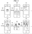
- Figure 3 shows the various software steps 300 which would take place when a patient downloads the software on to their telecommunication device in the format of a mobile phone so as to be able to access the medicine from the dispensing container.
- a patient would first download 302 the software onto their phone, during which a standard "download" screen 304 illustrating the time remaining for the software to be downloaded and installed on the phone will be presented to the user.
- the patient would then insert their ID code 310 which is linked to the visual recognition technology located either within the software on the phone or on a remote server.
- the patient After the patient has inserted their ID code 310 on the "enter pin" 312 screen the patient is then prompted to take a photo 314 by means of a "take self photo” screen 316.
- a photo capture step 318 takes place where the patient 320 takes a photograph of their face using the integrated camera on the mobile phone and they then enter patient profile data 322 as requested on the patient profile page 324. By completing the patient profile in the software, this automatically activates 326 the dispensing container and enables the phone to start communicating directly with the microprocessor in the dispensing container 328.
- a single dose may be taken on time 330 as prompted by the software 332 and when a tablet has been taken from the container, the dose taken 334 is relayed back to the phone, and a "dose taken" 336 screen is presented on the phone.
- the data is then stored on the phone and also uploaded to the database 338 and confirmation that data has been uploaded to the server 340 is presented to the user screen.
- a reminder for a second dose at a second time period 342 is sent to the phone to alert the user via a reminder screen 344 and this prompts a photograph to be taken for authentication 346 and provided that the person who is photographed is recognised as the same picture in the original photo capture 318, the dispensing container is authorised to dispense a further dose and steps 332 to 348 repeated 350 as necessary.
- the bottle 402 is a standard pharmaceutical tablet bottle which has a neck 404 with a threaded shank 408 for sealing with a sealing cap.
- a dispensing cap having a cap housing 406 has been rotated received onto the threaded of the neck of the bottle 404 in a secure matter. It is desirable for the cap housing 406 to be permanently affixed around the neck of the bottle 404 such that it cannot be removed.
- the cap housing 406 houses a battery 410 for powering the electronic circuitry within the cap housing 406.
- An access flap 412 is shown in a closed configuration at the base of the cap housing.
- the access flap can move to open configuration (shown in hatched lines 412b).
- the flap 412, 412b pivots about a hinge 414 and permits the flap to move in an arcuate direction 413.
- the cap housing 406 also incorporates an aerial 416 for communicating with an external device such as a mobile phone.
- the aerial 416 is operably connected to a microprocessor 418 which in turn is connected to a locking mechanism 420 for controlling the movement of the access flap 412.
- the locking mechanism 420 comprises an electromagnet 422 which can abut a strip of ferrous material 424 located on the interior surface of the access flap 412.
- a number of pharmaceutical tablets 426 which can be received within a channel of the access flat 412 so that a single tablet can be dispensed during one access flap opening.
- a schematic telecommunication device 430 is shown which is in wireless communication 432 with the microprocessor 418 via the aerial 416.
- the cap 406 could be retrofitted to the bottle, or simply formed or affixed onto the bottle during the normal packaging process.
- a patient wishes to ingest a pharmaceutical tablet 426, they use the system 200 and take the necessary steps on their phone 300 to effect a positive ID authentication from the telecommunication device 430 which is sent wirelessly 432 to the aerial 416 of the cap housing 406.
- the microprocessor 418 upon receipt of an authentication code disengages the electromagnetic locking arrangement 422 so as to release the access flap 412 so that it moves to an open configuration 412b and a single pharmaceutical tablet 426b is presented to the user for consumption.
- the user then pushes the access flap 412b back towards the cap housing 406 and the microprocessor 418 automatically activates the electromagnet 422 which secures the access flap to the strip of ferrous material 424.
- Different locking mechanisms may also be deployed.
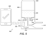
- Figure 5 shows a bottle with aerosol dispenser in accordance with an example not within the scope of the claims.
- an aerosol can 502 is received within a dispenser housing 506.
- the dispenser housing 506 also contains a battery 510 which powers a microprocessor 518 and the locking mechanism 522.
- a liquid pharmaceutical medicine 526 is contained within the aerosol can and is capable of being in fluid communication with the liquid aerosol dispensing nozzle 512 when the locking mechanism 522 has been disengaged.
- the aerosol dispenser also communicates with a telecommunication device 530 via an aerial 516 using a wireless connection 532.
- the telecommunication device 530 transmits a user authentication signal to the microprocessor 518 via the aerial 516, it disengages the locking mechanism 522 for a single metered dose of the liquid pharmaceutical medicine 526 via the liquid aerosol dispensing nozzle 512. After the single does has been dispensed, the locking mechanism 522 engages so as to prevent any further doses being dispensed until such time that an authentication code is again provided by the telecommunication device 530.
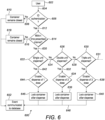
- the user 602 is required 604 to provide ID authentication 606 to the container. If no ID authentication is provided 608, the container remains closed 610. If a ID authentication 606 is provided 612, then is the request for a further pharmaceutical dose within the prescribed time interval 614? If the request is not within the prescribed time frame 616, then the container remains closed. If the request is within the prescribed time interval 620, the system then needs to establish whether a single dose 622 is required.
- the container is enabled to dispense one dose 644 after which, the container is locked 646 after dispensing the dose. If more than one single dose is required 624 is a double dose required 626? If yes 632, then the container is enabled to dispense 2 doses 634 before the container is locked 636. If more than 2 doses are required 628, then if a triple dose is required 630, the container is enabled to dispense 3 doses 638, after which the container is locked 640. The process continues 631 depending on the number of doses required. If a single, double or triple (646, 636, 640) has been dispensed then the event is communicated 648 to a central database 652. If unauthorised requests or out of time interval requests have been received (610, 618), then this information is also relayed 650 to the central database 652.
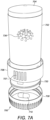
- Figure 7A illustrates a dispensing container which is similar in its mode of action to a dispensing container as described with reference to (and as illustrated in) Figure 1 .
- the dispensing container 700 of this embodiment has an outer cylindrical body 702 which is closed at the top by means of a weighted top cap 704.
- Extending circumferentially around the base of the outer cylindrical body 702 is an outer rim 706 having a number of longitudinally extending projections 707 forming easy to grip features on the rim.
- a threaded shank 720 Directly under the outer rim 706 is a threaded shank 720 around which is secured a rotatably removable base cap 708.
- the base cap 708 is shown in a position away from the outer cylindrical body 702 and contains a pharmaceutical tablet 710 which has been dispensed.
- the base cap 708 has a flat lower surface (not shown) which is used to support the container in an upright fashion when resting on a flat surface.
- the direction of the flow of the pharmaceutical tablet 710 out of the cylindrical body 702 is illustrated by the arrow denoted 712 which shows that the tablet 710 is dispensed into the removable base cap 708 via a chute 713 located towards the bottom of the cylindrical body 702.
- a rotatable star 714 which is in the configuration of a small cylinder which is rotatable along the longitudinal axis of the cylindrical body 702 and from which 8 fins 715 extend in a radial fashion.
- the spacing of the radial fins 715 corresponds to longer fins 716 located on a static star 717 located above the rotatable star 714 which is connected to a ratchet mechanism (not shown).
- the longer fins 716 form channels within the star 718 and enable end-to-end vertical stacking of pharmaceutical tablets 710.
- the chute 713 abuts a lower disc 724 located beneath the rotatable star 714.
- the lower disc 724 is provided with an aperture 722 for allowing the pharmaceutical tablet 710 to be dispensed into the removable base cap 708 when desired.
- a drive mechanism, power source and communication arrangement In a central portion of the dispensing container 700, there is provided a drive mechanism, power source and communication arrangement.
- An AA battery 726 provides power to a motor 732 which is adapted to rotate the rotatable star 714 via a gearing mechanism 730.
- a microprocessor 728 is provided and attached to a communication arrangement (such as an antenna and Bluetooth ® communication software).
- the dispensing device 700 operates in a very similar manner as to the dispensing device illustrated in Figure 1 .
- the dispensing container 700 forces the user to keep the device in an upright configuration as the top cap 704 is weighted such that if the container is not held or placed on a surface in a vertical manner, the container will be unstable and topple over.
- This feature is important as it forces the user to keep the dispensing container in its upright configuration which permits the pharmaceutical tablet 710 to be gravity fed into the rotatable star 714 and ultimately into the removable base cap 708.
- the top cap 704 also permits the dispensing container to be easily filled at a production facility or a pharmacy.
- pharmaceutical tablets 710 are stacked end-to-end within the static star channels 718 and the stack extends into the space formed between the fins 715 of the rotatable star 714.
- the rotatable star 714 is powered by the battery 726 drives the motor 732 which in turn activates the gearing mechanism 730 and very rotates the ratchet mechanism of the rotatable star 714 in a direction 734.
- the pharmaceutical tablet is able to drop by gravity through the aperture 722 in the lower disc 724 and into the removable base cap 708.
- a dispensing sensor (not shown) may also be provided for validation purposes which detects and confirms the dispensation of a tablet 710.
- a dispensing sensor may be a micro-switch arrangement which detects the physical passage of the tablet or a light sensor which can detect the optical passage of the tablet.
- the dispensing sensor may be located adjacent to or within the chute 713.
- the microprocessor 728 can not only control the speed of the rotation of the rotatable star 714 through the gearing arrangement 730, but may also communicate the removal of the base cap 708 and/or the dispensing of a tablet 710 through the aperture 722 (which may include validation of the dispensing by utilising the dispensing sensor) to a remote server for compliance monitoring. Should dispensing action not be validated by the dispensing sensor, then an error signal may be sent to the remote server for appropriate action.
- the dispensing container 700 could be used in conjunction with an authentication protocol so that the rotatable star 714 only rotates to a position to allow a pharmaceutical tablet 710 to be dispensed through the chute 713 and aperture 712 upon receipt of an authorisation signal.
- the dispensing container 700 is particularly suited for the timed dispensation of drug rehabilitation treatments such as methadone, as the dispensing container cannot be opened by the user and will only dispense tablets at prescribed time points.
- drug rehabilitation treatments such as methadone
- an override system may also be provided to enable dispensation of tables in emergencies and/or malfunction of the software or mechanism.
- the dispensing container 700 may be used in conjunction with the system 200 (shown in (and described with reference to) Figure 2 ) for configuring a dispensing container with a remote database, in addition to using the software steps 300 (shown in (and described with reference to) Figure 3 ) and lastly the necessary steps a user may take in order to obtain a pharmaceutical dose from a dispensing container using the steps 600 (shown in (and described with reference to) Figure 6 ).
- the advancement of the tablet 710 through the chute 713 may be by the user twisting the collar 706 which would be operably connected to the rotatable star 714 in such a manner that the twisting action would rotate the fins 715 enough so that a tablet could be dispensed.
- the dispensing container 800 is formed of a standard tablet bottle 802, upon which is attached a dispensing lid 804.
- the dispensing lid 804 is formed of a bottle sealing rim 806 and a dispensing portion 808.
- the dispensing portion 808 has a dispensing counter 810 and an aperture 812 through which pharmaceutical tablets 814 can be dispensed.
- the tablet bottle 802 has a label 816 having a unique barcode 818 included thereon.
- the bottle sealing rim 806 is statically received on the tablet bottle 802, but permits the dispensing portion 808 to rotate in a clockwise direction 820 by 90° so as to enable a pharmaceutical tablet 814 to be dispensed through the aperture 812 in the direction indicated by the arrow 822.
- the dispensing portion 808 is spring loaded and after dispensing a tablet, it counter rotates in an anti-clockwise direction by 90° and therefore assumes its original position ready for the next tablet to be dispensed.
- the tablet bottle 802 will be filled with pharmaceutical tablets 814 which may contain a medicine such as a severe pain relief formulation.
- a medicine such as a severe pain relief formulation.
- the dispensing counter 810 is advanced by an additional number, thus indicating the total number of tablets dispensed.
- the dispensing counter 810 may be analogue or digital and may be in the form of a LED or LCD display.
- the dispensing container 800 may be used simply to allow an individual track the number of doses taken from the bottle or the container could be utilised for more active monitoring of the dispensing of the tablets from the bottle.
- an image capture device 824 (such as a camera on a smartphone) may be used to take an image of the whole of the dispensing container 800 or a first 826 and/or second 828 focus area.
- the image capture device 824 may be further refined to take two images or to focus on two areas of the bottle, namely the dispensing counter 810 and the label 816 which contains a unique barcode 818.
- a barcode 826 may be attached near to the dispensing counter 810 so that the image capture device need only be focused towards the first focus area thus removing the need to receive an image from the second focus area 828.
- the dispensing container 800 could be used in a number of ways, although it is envisaged that a smartphone (not shown) is used to relay when a dose from the bottle has been taken by sending data from the display counter 810 and unique barcode 818 (or 826) to a remote server for dose monitoring and/or reordering purposes.
- Figure 9 shows a similar dispensing container as shown in Figures 7A-7C .
- the dispensing container 700' also includes a counter 750 which counts the numbers of tablets dispensed in a similar manner to the counter 810 and also a unique barcode 760.
- the counter 750 may also be able to log and display additional information such as the time the last table was dispensed, how many tablets have been dispensed so far and how many tablets remain in the container.
- the dispensing container 700' can be used (either additionally or alternatively) in a similar way as shown and described with reference to Figures 8A-C , where a imaging device (such as a smart phone) is used to track and relay information about the frequency and timing of tablet dispensation.
- a imaging device such as a smart phone
- the counter could also include an alert function such as flashing or audible alarm in order to remind an individual to take another dose.
- the devices and system as described with reference the aforementioned embodiments can be used not only to prevent unauthorised access to the medicines within the containers (for example to reduce the likelihood of children gaining access to pharmaceutical products) but they can also be used to monitor patient compliance and ensure correct dosage regimes are followed in accordance with the recommended guidelines.
- a telecommunication device such as a "smartphone”
- software embedded in the phone or a computer program operating on the phone can automatically remind patients to take the medicines at the correct timings and the software can also include features to take account of patients travelling between time zones, whilst maintaining correct dosage regimes which are often difficult for travellers etc.
Description
- The invention relates to reclosable dispensers and to systems and methods of dispensing (and additionally tracking and recording the dispensing of) products, such as pharmaceuticals, to the intended recipient.
- Products, such as pharmaceuticals and dietary supplements can be dangerous if incorrectly administered or taken by someone other than the intended recipient (by a child for example). Most medicines need to be administered under a particular regimen to be effective, however, some patients take two does of the medicine if they have missed a previous dose which could be extremely harmful. Lastly, there are issues with patient dose compliance which is often hard to establish by physicians and can lead to further unnecessary treatments or provide incorrect clinical trial data.
- A number of devices and systems have been proposed which try and identify compliance issues with patient pharmaceutical administration.
-
GB2483221 -
US20140266760 describes a tablet container cap which incorporates sensors, chips, transmitters, and receiver, to record, transmit, and receive data regarding the time intervals between when the container cap was last placed on or taken off of a container. The container cap is for use with pharmaceutical and other health care related vials, bottles and containers. - The data transmission is used to monitor a patient's drug administration times and intervals, and allows the patient and/or the patient's caregiver to review the administration data.
-
US20140297312 discloses computer-based systems and computer-implemented methods for monitoring medication events for an individual. -
US2013197693 discloses a pill dispenser includes a housing, a pill-dispensing mechanism, a receptacle, a pill-viewing camera, an identifying camera, one or more processors, and a storage medium. -
US2010100237 discloses a dispenser having means to dispense desired number of pills from a bulk supply of pills contained in the dispenser. -
WO0215135 -
US6561377 discloses a vacuum driven pill counter includes a counter housing with a pill discharge aperture formed therein. An integrally formed vacuum drum is rotatably positioned in the housing and the vacuum drum includes a front wall, a rear wall, and a perimeter wall. The front wall of the vacuum drum has a plurality of pill apertures formed therein. -
US2013/0035785 discloses a pill dispenser for dispensing pills of various sizes includes a pill storage section, a dispensing section located at a lower end of the storage section, an optical sensor, a memory and a controller. -
US2006/0071011 discloses an electronic pill dispenser includes a container and a cap removably attached to the container. - All of the above systems and methods are aimed at monitoring dose administration. However none of the prior art systems and methods actively prevent administration to anyone other than the patient (or patient carer) or indeed permit stricter compliance with the desired dosage regime. An object of the present invention is to address one or more of the above problems associated with the prior art. It is also an object of the present invention to provide for a dispenser, system or method which prevents administration of a medicine to anyone other than the patient (or patient carer) and optionally only dispenses the medicine in the desired dose within the correct time interval. It is also an object to provide for a dispenser, system or method which actively monitors dose compliance and interacts with a medical records or clinical trial data systems.
- In accordance with a first aspect of the present invention, there is provided a dispenser as described with reference to appended
claim 1. - The receiver may be further adapted for receiving a permitted time interval signal or the permitted time interval has lapsed and the dispenser only permits the opening of the reclosable opening upon additionally receiving a permitted time interval signal or a permitted time interval has lapsed. This can be used to prevent the unit (such as a pharmaceutical) from being dispensed too frequently or not within the desired time window.
- The receiver is adapted for receiving or assessing whether the user is within a prescribed vicinity of the dispenser and only permits the opening of the reclosable opening upon additionally determining if the user is within the prescribed vicinity. This feature can ensures that the opening of the reclosable opening is only permitted if the user is close by if it is not desired to permit remote opening.
- The user authentication signal may be provided by successfully identifying an authorised user by using one or more of the following: facial recognition, finger prints, retina scan, PIN code or password. It will be apparent that a number of other methods of identifying an authorised user may be employed such as voice signatures.
- Preferably the user authentication signal is provided upon verifying the user against identification data located on the dispenser or a remote server.
- The receiver may be formed as part of a transceiver to enable the dispenser to receive and also submit signals. Such a transceiver may transmit a dispensing signal and/or receipt of an authentication signal to the remote server. This transmission may be via one or more intermediate communication devices.
- The authentication signal is provided by a remote device.
- A dispensing sensor may be provided which senses when one or more units of product has been advanced towards or through the reclosable opening. The dispensing sensor could comprise a micro-switch arrangement which detects the physical passage of the unit or a light sensor which can detect the optical passage of the unit. The dispensing sensor can be used to provide a dispensing validation signal. The dispensing sensor provides a 'double check' that the unit has indeed been dispensed to prevent false positive dispensing events being logged.
- The transceiver may transmit the dispensing signal and/or a dispensing validation signal and/or receipt of an authentication signal to the remote server via the remote device. The device may be configured so that both a dispensing signal and/or a dispensing validation signal are required to confirm that a unit has been dispensed and should the device transmit a dispensing signal without a dispensing validation signal, then an error can be identified by either the remote device or remote server and a remedial course of action permitted.
- The remote device will preferably comprise a radio electronic transmitter. A radio electronic transmitter may comprise a range of telecommunication devices, such as a mobile phone. The term "mobile phone", "telecommunication device" and "cell phone" can be used interchangeably and are intended to be used to describe mobile communication devices which are capable of communicating wirelessly with the dispenser and also a remote server if desired.
- The term "signal" may encompass a number of different electronic communication signals, such as a radio signal.
- The controller may comprise a micro-switch arrangement which controls the opening of the reclosable opening. The controller may comprise a motor which acts to advance one or more units of product towards or through the reclosable opening. Preferably, the units of product are advanced by means of the motor powering a ratchet arrangement, whereby a single unit is advanced towards or through the reclosable opening. Such a ratchet arrangement would prevent further product units advancing towards or through the reclosable opening as the arrangement would essentially be locked until powered by the motor again. Alternatively, the units of product are advanced by means of the motor continually powering a mechanism, which optionally may include gearing, so that the units of product are advanced towards or through the reclosable opening at particular time intervals which correlate to speed of the motor and/or mechanism. Additional mechanical and/or electro-mechanical arrangements for controlling the opening of the reclosable opening will of course be apparent to the skilled addressee.
- The dispenser can be used for dispensing a number of different items but it is particularly suited to products comprising pharmaceutical, nutraceutical, nutritional or dietary supplements. The opening of the reclosable opening may permit only a single or metered dose of the product to be dispensed. The product may be in the form of a tablet or capsule. In the alternative, the product may be in the form of a liquid, powder or suspension.
- The one or more units of product may be gravity fed to the reclosable opening. Preferably, the dispenser is configured to be stored or held upright so as to enable one or more units of the product to be gravity fed to the reclosable opening. The dispenser may be in the form of a cylindrical housing having a base and a top and where the base is larger than the top. Additionally, the top may be substantially convex and optionally weighted so as to make the dispenser unstable unless it is stored in an upright position resting upon its base.
- It will be apparent to the skilled addressee that the dispenser may be retro-fitted to the opening of an existing container, such as a typical medical bottle or metered inhaler.
- There is also disclosed a dispensing system in accordance with claim 13.
- There is further disclosed a method of dispensing at least one unit of a product from the cavity of a container to an authorised user in accordance with claim 14.
- Embodiments of the present invention will now be described, by way of example only, with reference to the following examples and accompanying figures, in which:
-
Figure 1A is a perspective view of a dispensing container in accordance with the present invention; -
Figure 1B is an exploded cross-section perspective view of the dispensing container as shown inFigure 1A ; -
Figure 1C is an exploded perspective view of the dispensing container as shown inFigure 1A ; -
Figure 2 is a schematic diagram for illustrating the steps undertaken by a doctor and patient in order to use the dispensing container of the present invention and their interaction with a remote database; -
Figure 3 is a schematic flow diagram of how a user may implement part of the invention using a mobile phone; -
Figure 4A is a cross-sectional diagram of an example not within the scope of the claims dispensing container, where a standard tablet bottle is fitted with a cap capable of dispensing tablets in accordance with the present invention; -
Figure 4B is a side-view along view axis A-A (as shown inFigure 4A ) illustrating how the dispensing cap would present and dispose a tablet to a user; -
Figure 5 shows a yet further example of a dispensing container not within the scope of the claims where the container contains a liquid and the housing is capable of dispensing a spray to a patient; -
Figure 6 is a schematic flow-diagram illustrating the steps a patient would make during the operation of the dispensing container of the present invention; and -
Figure 7A is a perspective view of a dispensing container in accordance with a further aspect of the present invention, where the end cap has been removed; -
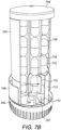
Figure 7B is a cross-sectional view of the dispenser shown inFigure 7A , where the end cap has not been removed; -
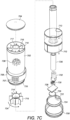
Figure 7C is an exploded perspective view of the component parts of the dispensing container shown inFigure 7A and7B ; -
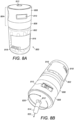
Figure 8A is a perspective view of a yet further example not within the scope of the claims; -
Figure 8B is a further perspective view of the dispensing container as shown inFigure 8A ; -
Figure 8C is a front view of the dispensing container shown inFigure 8B , showing outlined boxes which may be photographed/analysed by an imaging device; and -
Figure 9 shows a similar dispensing container as shown inFigures 7A-7C but differs in the fact that it contains a tablet counter and bar code. - With reference to
Figure 1A-C , there is shown a dispensingcontainer 100 in accordance with a first embodiment of the present invention. The dispensingcontainer 100 comprises acylindrical housing 102 having a round top at the top end of thecylindrical housing 102 and adispensing base disc 106 located at the bottom end of thecylindrical housing 102. Aremovable base cap 108 covers the dispensingbase disc 106 and is removably attached to thecylindrical housing 102 by means ofprojections 122 can be rotatably received around the threadedshank 120 of thecylindrical housing 102. - As shown in
Figure 1B , apharmaceutical tablet 110 is located within the main body of the cylindrical housing and when placed in an upright position (as shown inFigure 1B ) thetablet 110 slides downwardly under gravity along the downwardly extending slopedinner wall 112 before passing down through thehousing chute 113 and continues in adownwardly direction 114 and on to a surface of the dispensingbase disc 106. The tablet can continue in adownwardly direction 116 through anaperture 117 in thedispensing disc 106 so that it ultimately falls into theremovable base cap 108. When theremovable base cap 108 is unscrewed, the cap can be moved away from thecylindrical housing 102 in adirection 118 so that the tablet can be easily removed by the user from the cap with their fingers and ingested by a patient. Thecylindrical housing 102 also incorporatedelectronic circuitry 124 assessing user authentication and dispensing the tablet from the cylindrical housing through a dispensingflap 126 located at the exit of thecylindrical housing chute 113. - In use, each dispensing
container 100 will be given a unique ID code which will be stored within theelectronic circuitry 124 and the code will also be printed on the exterior of thecylindrical housing 102. The dispensingcontainer 100 will be filled on a high speed (standard) pharmaceutical tablet bottling line and subsequently labelled and collated ready for shipping to the pharmacy. A pharmacist will dispense the bottle to the patient and the patient will then follow the instructions provided in order to permit access to the medication as and when required (as described with reference to later figures). - When a patient wishes to ingest a
pharmaceutical tablet 110, they will first have to transmit a authentication code to theelectronic circuitry 124 in order for the dispensingflap 126 to be opened and a tablet permitted to pass through the dispensingbase disc 106 and into theremovable cap 108. It is preferred that the code is provided wirelessly via a mobile phone which is configured only to provide the authentication ID after the identification of the user has - been verified (either by means of facial recognition, fingerprint scanning, retina scan, pin code or password).
- Turning to
Figure 2 , there is shown schematically thesystem 200 of how a dispensing container as shown inFigures 1A-1C is configured to interact with a remote database. A doctor (or healthcare professional) 202 provides a prescription-dose regime 204 which includes a unique 1D code. Theprescription 204 is given to thepatient 206 who in turn passes it to apharmacist 208 who provides the dispensing container which contains the required pharmaceutical tablets. The dispensing container is pre-packaged or self-packaged with a script and further ID digits. The patient then downloads a computer program (commonly referred to as an "app") to their telecommunication device using the ID code. In order to activate the computer program, the software prompts the use to take a photograph of themselves for future user verification. The dispensing container is then fully activated 212 and can dispense pharmaceutical tablets at the prescribed dose and time but only after the user has presented their face to the camera of the telecommunication device so as to provide a positive ID in the form offacial recognition 214.Data 218 is sent from and received by the telecommunication device anddatabase 216 via any knowncommunication route 220. Thedatabase 216 optionally provides the 1D codes during theprescription step 204 and may also house the software for the patient to download 224. If desired, thedatabase 216 could be stored on a cloud based server or a hosted server with a secure network connection. It will be apparent to the skilled person, that duringstep 210, the patient need not necessarily download the software afresh, if the software already exists on their telecommunication device for a similar/repeat prescription or indeed a different prescription which is intended to be prescribed in the same manner. -
Figure 3 shows thevarious software steps 300 which would take place when a patient downloads the software on to their telecommunication device in the format of a mobile phone so as to be able to access the medicine from the dispensing container. A patient would first download 302 the software onto their phone, during which a standard "download"screen 304 illustrating the time remaining for the software to be downloaded and installed on the phone will be presented to the user. The patient would then insert theirID code 310 which is linked to the visual recognition technology located either within the software on the phone or on a remote server. After the patient has inserted theirID code 310 on the "enter pin" 312 screen the patient is then prompted to take aphoto 314 by means of a "take self photo"screen 316. Aphoto capture step 318 takes place where thepatient 320 takes a photograph of their face using the integrated camera on the mobile phone and they then enterpatient profile data 322 as requested on thepatient profile page 324. By completing the patient profile in the software, this automatically activates 326 the dispensing container and enables the phone to start communicating directly with the microprocessor in the dispensingcontainer 328. A single dose may be taken ontime 330 as prompted by thesoftware 332 and when a tablet has been taken from the container, the dose taken 334 is relayed back to the phone, and a "dose taken" 336 screen is presented on the phone. The data is then stored on the phone and also uploaded to thedatabase 338 and confirmation that data has been uploaded to theserver 340 is presented to the user screen. When a further dose is required, a reminder for a second dose at asecond time period 342 is sent to the phone to alert the user via areminder screen 344 and this prompts a photograph to be taken forauthentication 346 and provided that the person who is photographed is recognised as the same picture in theoriginal photo capture 318, the dispensing container is authorised to dispense a further dose and steps 332 to 348 repeated 350 as necessary. - With reference to
Figure 4 , there is shown abottle 400 with a dispensing cap in accordance with an example not within the scope of the claims. Thebottle 402 is a standard pharmaceutical tablet bottle which has aneck 404 with a threadedshank 408 for sealing with a sealing cap. A dispensing cap having acap housing 406 has been rotated received onto the threaded of the neck of thebottle 404 in a secure matter. It is desirable for thecap housing 406 to be permanently affixed around the neck of thebottle 404 such that it cannot be removed. - The
cap housing 406 houses abattery 410 for powering the electronic circuitry within thecap housing 406. Anaccess flap 412 is shown in a closed configuration at the base of the cap housing. The access flap can move to open configuration (shown in hatchedlines 412b). Theflap hinge 414 and permits the flap to move in anarcuate direction 413. Thecap housing 406 also incorporates an aerial 416 for communicating with an external device such as a mobile phone. The aerial 416 is operably connected to amicroprocessor 418 which in turn is connected to alocking mechanism 420 for controlling the movement of theaccess flap 412. Thelocking mechanism 420 comprises anelectromagnet 422 which can abut a strip offerrous material 424 located on the interior surface of theaccess flap 412. Within thebottle 402 are a number ofpharmaceutical tablets 426 which can be received within a channel of the access flat 412 so that a single tablet can be dispensed during one access flap opening. Aschematic telecommunication device 430 is shown which is inwireless communication 432 with themicroprocessor 418 via the aerial 416. - As the
bottle 402 may be a standard bottle, thecap 406 could be retrofitted to the bottle, or simply formed or affixed onto the bottle during the normal packaging process. When a patient wishes to ingest apharmaceutical tablet 426, they use thesystem 200 and take the necessary steps on theirphone 300 to effect a positive ID authentication from thetelecommunication device 430 which is sent wirelessly 432 to the aerial 416 of thecap housing 406. Themicroprocessor 418, upon receipt of an authentication code disengages theelectromagnetic locking arrangement 422 so as to release theaccess flap 412 so that it moves to anopen configuration 412b and a singlepharmaceutical tablet 426b is presented to the user for consumption. The user then pushes theaccess flap 412b back towards thecap housing 406 and themicroprocessor 418 automatically activates theelectromagnet 422 which secures the access flap to the strip offerrous material 424. Different locking mechanisms may also be deployed. -
Figure 5 shows a bottle with aerosol dispenser in accordance with an example not within the scope of the claims. - In this embodiment, an aerosol can 502 is received within a
dispenser housing 506. Thedispenser housing 506 also contains abattery 510 which powers amicroprocessor 518 and thelocking mechanism 522. A liquidpharmaceutical medicine 526 is contained within the aerosol can and is capable of being in fluid communication with the liquidaerosol dispensing nozzle 512 when thelocking mechanism 522 has been disengaged. In common with the bottle with dispensing cap in accordance with the example shown inFig. 4 ., the aerosol dispenser also communicates with atelecommunication device 530 via an aerial 516 using awireless connection 532. Again, when thetelecommunication device 530 transmits a user authentication signal to themicroprocessor 518 via the aerial 516, it disengages thelocking mechanism 522 for a single metered dose of the liquidpharmaceutical medicine 526 via the liquidaerosol dispensing nozzle 512. After the single does has been dispensed, thelocking mechanism 522 engages so as to prevent any further doses being dispensed until such time that an authentication code is again provided by thetelecommunication device 530. - With reference to
Figure 6 , there is shown aschematic flow chart 600 of the necessary steps a user may take in order to obtain a pharmaceutical dose from a dispensing container in accordance with embodiments of the present invention. Theuser 602 is required 604 to provideID authentication 606 to the container. If no ID authentication is provided 608, the container remains closed 610. If aID authentication 606 is provided 612, then is the request for a further pharmaceutical dose within theprescribed time interval 614? If the request is not within theprescribed time frame 616, then the container remains closed. If the request is within theprescribed time interval 620, the system then needs to establish whether asingle dose 622 is required. If only a single dose is required 642 then the container is enabled to dispense onedose 644 after which, the container is locked 646 after dispensing the dose. If more than one single dose is required 624 is a double dose required 626? If yes 632, then the container is enabled to dispense 2doses 634 before the container is locked 636. If more than 2 doses are required 628, then if a triple dose is required 630, the container is enabled to dispense 3doses 638, after which the container is locked 640. The process continues 631 depending on the number of doses required. If a single, double or triple (646, 636, 640) has been dispensed then the event is communicated 648 to acentral database 652. If unauthorised requests or out of time interval requests have been received (610, 618), then this information is also relayed 650 to thecentral database 652. -
Figure 7A illustrates a dispensing container which is similar in its mode of action to a dispensing container as described with reference to (and as illustrated in)Figure 1 . With reference toFigure 7A-7C , the dispensingcontainer 700 of this embodiment has an outercylindrical body 702 which is closed at the top by means of a weightedtop cap 704. Extending circumferentially around the base of the outercylindrical body 702 is anouter rim 706 having a number of longitudinally extendingprojections 707 forming easy to grip features on the rim. Directly under theouter rim 706 is a threadedshank 720 around which is secured a rotatablyremovable base cap 708. InFigure 7A , thebase cap 708 is shown in a position away from the outercylindrical body 702 and contains apharmaceutical tablet 710 which has been dispensed. Thebase cap 708 has a flat lower surface (not shown) which is used to support the container in an upright fashion when resting on a flat surface. The direction of the flow of thepharmaceutical tablet 710 out of thecylindrical body 702 is illustrated by the arrow denoted 712 which shows that thetablet 710 is dispensed into theremovable base cap 708 via achute 713 located towards the bottom of thecylindrical body 702. - Towards the base of the
cylindrical body 702 is arotatable star 714 which is in the configuration of a small cylinder which is rotatable along the longitudinal axis of thecylindrical body 702 and from which 8fins 715 extend in a radial fashion. The spacing of theradial fins 715 corresponds tolonger fins 716 located on astatic star 717 located above therotatable star 714 which is connected to a ratchet mechanism (not shown). Thelonger fins 716 form channels within thestar 718 and enable end-to-end vertical stacking ofpharmaceutical tablets 710. - The
chute 713 abuts alower disc 724 located beneath therotatable star 714. Thelower disc 724 is provided with anaperture 722 for allowing thepharmaceutical tablet 710 to be dispensed into theremovable base cap 708 when desired. - In a central portion of the dispensing
container 700, there is provided a drive mechanism, power source and communication arrangement. AnAA battery 726 provides power to amotor 732 which is adapted to rotate therotatable star 714 via agearing mechanism 730. Amicroprocessor 728 is provided and attached to a communication arrangement (such as an antenna and Bluetooth® communication software). - In use, the
dispensing device 700 operates in a very similar manner as to the dispensing device illustrated inFigure 1 . When assembled, the dispensingcontainer 700 forces the user to keep the device in an upright configuration as thetop cap 704 is weighted such that if the container is not held or placed on a surface in a vertical manner, the container will be unstable and topple over. This feature is important as it forces the user to keep the dispensing container in its upright configuration which permits thepharmaceutical tablet 710 to be gravity fed into therotatable star 714 and ultimately into theremovable base cap 708. Thetop cap 704 also permits the dispensing container to be easily filled at a production facility or a pharmacy. - Initially,
pharmaceutical tablets 710 are stacked end-to-end within thestatic star channels 718 and the stack extends into the space formed between thefins 715 of therotatable star 714. When the dispensing container is activated, therotatable star 714 is powered by thebattery 726 drives themotor 732 which in turn activates thegearing mechanism 730 and very rotates the ratchet mechanism of therotatable star 714 in adirection 734. When thetablet 710 is rotated to a position adjacent to thechute 713, the pharmaceutical tablet is able to drop by gravity through theaperture 722 in thelower disc 724 and into theremovable base cap 708. A dispensing sensor (not shown) may also be provided for validation purposes which detects and confirms the dispensation of atablet 710. A dispensing sensor may be a micro-switch arrangement which detects the physical passage of the tablet or a light sensor which can detect the optical passage of the tablet. The dispensing sensor may be located adjacent to or within thechute 713. When the user is ready to take their medicine, they simply unscrew theremovable base cap 708 and remove thepharmaceutical tablet 710 and then consume it for their treatment. Therotatable star 714 can be pre-set to rotate at a particular speed so that one ormore tablets 710 are dispensed at pre-determined time points. Themicroprocessor 728 can not only control the speed of the rotation of therotatable star 714 through thegearing arrangement 730, but may also communicate the removal of thebase cap 708 and/or the dispensing of atablet 710 through the aperture 722 (which may include validation of the dispensing by utilising the dispensing sensor) to a remote server for compliance monitoring. Should dispensing action not be validated by the dispensing sensor, then an error signal may be sent to the remote server for appropriate action. Alternatively, the dispensingcontainer 700 could be used in conjunction with an authentication protocol so that therotatable star 714 only rotates to a position to allow apharmaceutical tablet 710 to be dispensed through thechute 713 andaperture 712 upon receipt of an authorisation signal. The dispensingcontainer 700 is particularly suited for the timed dispensation of drug rehabilitation treatments such as methadone, as the dispensing container cannot be opened by the user and will only dispense tablets at prescribed time points. Of course, an override system may also be provided to enable dispensation of tables in emergencies and/or malfunction of the software or mechanism. - The dispensing
container 700 may be used in conjunction with the system 200 (shown in (and described with reference to)Figure 2 ) for configuring a dispensing container with a remote database, in addition to using the software steps 300 (shown in (and described with reference to)Figure 3 ) and lastly the necessary steps a user may take in order to obtain a pharmaceutical dose from a dispensing container using the steps 600 (shown in (and described with reference to)Figure 6 ). - As a further modification to the dispensing
container 700, or as an emergency back-up, the advancement of thetablet 710 through thechute 713 may be by the user twisting thecollar 706 which would be operably connected to therotatable star 714 in such a manner that the twisting action would rotate thefins 715 enough so that a tablet could be dispensed. There may be an additional mechanism included which prevents the rotation of the collar (and therefore dispensation of the tablet) unless the prescribed time had lapsed or a correct authentication code had been received. - With reference to
figures 8A-8A , there is a yet further dispensingcontainer 800 shown related to an example not within the scope of the claims. - The dispensing
container 800 is formed of astandard tablet bottle 802, upon which is attached a dispensinglid 804. The dispensinglid 804 is formed of abottle sealing rim 806 and a dispensingportion 808. The dispensingportion 808 has a dispensingcounter 810 and anaperture 812 through whichpharmaceutical tablets 814 can be dispensed. Thetablet bottle 802 has alabel 816 having aunique barcode 818 included thereon. - The
bottle sealing rim 806 is statically received on thetablet bottle 802, but permits the dispensingportion 808 to rotate in aclockwise direction 820 by 90° so as to enable apharmaceutical tablet 814 to be dispensed through theaperture 812 in the direction indicated by thearrow 822. The dispensingportion 808 is spring loaded and after dispensing a tablet, it counter rotates in an anti-clockwise direction by 90° and therefore assumes its original position ready for the next tablet to be dispensed. - In use, the
tablet bottle 802 will be filled withpharmaceutical tablets 814 which may contain a medicine such as a severe pain relief formulation. When the user wishes to take a medicine, they simply rotate the dispensingportion 808 relative to thebottle 802 and apharmaceutical tablet 814 is dispensed through theaperture 812 in thedirection 822. As thetablet 814 passes through the dispensingportion 808 or theaperture 812, the dispensingcounter 810 is advanced by an additional number, thus indicating the total number of tablets dispensed. The dispensingcounter 810 may be analogue or digital and may be in the form of a LED or LCD display. - The dispensing
container 800 may be used simply to allow an individual track the number of doses taken from the bottle or the container could be utilised for more active monitoring of the dispensing of the tablets from the bottle. In the latter, an image capture device 824 (such as a camera on a smartphone) may be used to take an image of the whole of the dispensingcontainer 800 or a first 826 and/or second 828 focus area. Theimage capture device 824 may be further refined to take two images or to focus on two areas of the bottle, namely the dispensingcounter 810 and thelabel 816 which contains aunique barcode 818. Alternatively or additionally, abarcode 826 may be attached near to the dispensing counter 810 so that the image capture device need only be focused towards the first focus area thus removing the need to receive an image from thesecond focus area 828. - The dispensing
container 800 could be used in a number of ways, although it is envisaged that a smartphone (not shown) is used to relay when a dose from the bottle has been taken by sending data from thedisplay counter 810 and unique barcode 818 (or 826) to a remote server for dose monitoring and/or reordering purposes. - Lastly,
Figure 9 shows a similar dispensing container as shown inFigures 7A-7C . In view of this similar features have been denoted by the same reference numeral prime (`). The dispensing container 700' also includes acounter 750 which counts the numbers of tablets dispensed in a similar manner to thecounter 810 and also aunique barcode 760. Thecounter 750 may also be able to log and display additional information such as the time the last table was dispensed, how many tablets have been dispensed so far and how many tablets remain in the container. By including the counter, the dispensing container 700' can be used (either additionally or alternatively) in a similar way as shown and described with reference toFigures 8A-C , where a imaging device (such as a smart phone) is used to track and relay information about the frequency and timing of tablet dispensation. Furthermore, the counter could also include an alert function such as flashing or audible alarm in order to remind an individual to take another dose. - It will of course be apparent, that the devices and system as described with reference the aforementioned embodiments can be used not only to prevent unauthorised access to the medicines within the containers (for example to reduce the likelihood of children gaining access to pharmaceutical products) but they can also be used to monitor patient compliance and ensure correct dosage regimes are followed in accordance with the recommended guidelines. By utilising a telecommunication device such as a "smartphone", software embedded in the phone or a computer program operating on the phone can automatically remind patients to take the medicines at the correct timings and the software can also include features to take account of patients travelling between time zones, whilst maintaining correct dosage regimes which are often difficult for travellers etc.
- The configuration of the containers and dispensing mechanisms described above can of course be interchanged depending upon the precise application and therefore the foregoing embodiments are not intended to limit the scope of the protection afforded by the claims, but rather to describe examples of how the invention may be put into practice.
Claims (14)
- A dispenser (100) comprising:a) a reclosable opening (126) on a container having a cylindrical housing (102) for receiving at least one unit of a product (110) to be dispensed;b) a controller adapted for controlling the opening of the reclosable opening; (126)c) a receiver adapted for receiving a user authentication signal from a remote device;d) a power source for powering the controller and receiver; andwherein the dispenser only permits the opening of the reclosable opening upon the receiver receiving the user authentication signal,the receiver is further adapted for receiving or assessing whether the user is within a prescribed vicinity of the dispenser, and the user authentication signal indicates that an authorised user has been successfully identified by the remote device, and that the dispenser only permits the opening of the reclosable opening upon additionally determining that the user is within the prescribed vicinity of the dispenser,characterised in that electronic circuitry (124) for user authentication and dispensing the at least one unit of a product to be dispensed from the cylindrical housing are disposed within the container.
- A dispenser (100) as claimed in claim 1, wherein the receiver is further adapted for receiving a permitted time interval signal or the permitted time interval has lapsed and the dispenser only permits the opening of the reclosable opening upon additionally receiving a permitted time interval signal or a permitted time interval has lapsed.
- A dispenser (100) as claimed in any preceding claim, wherein the user authentication signal is provided by successfully identifying an authorised user by using one or more of the following: facial recognition, finger prints, retina scan, PIN code or password.
- A dispenser (100) as claimed in claim 3, wherein the user authentication signal is provided upon verifying the user against identification data located on a remote server.
- A dispenser (100) as claimed in any preceding claim, wherein the receiver is formed as part of a transceiver to enable the dispenser to receive and also submit signals.
- A dispenser (100) as claimed in any preceding claim, wherein the dispenser further comprises a dispensing validation sensor to sense the passage of one or more products through the reclosable opening.
- A dispenser (100) as claimed in claim 6, wherein upon sensing the passage of one or more products through the reclosable opening, the dispensing validation sensor produces a dispensing validation signal.
- A dispenser (100) as claimed in any one of claims 5 to 7, wherein the transceiver transmits a dispensing signal and/or a dispensing validation signal and/or a receipt of an authentication signal to a remote server.
- A dispenser (100) as claimed in any preceding claim, wherein the transceiver transmits a dispensing signal and/or a dispensing validation signal and/or receipt of an authentication signal to the remote server via the remote device.
- A dispenser (100) as claimed in any preceding claim, wherein the remote device comprises a telecommunication device.
- A dispenser (100) as claimed in any preceding claim, wherein the product comprises a pharmaceutical, nutraceutical, nutritional or dietary supplement.
- A dispenser (100) as claimed in claims 11, wherein the product is in the form of a tablet or capsule.
- A dispensing system comprising:a) a dispenser (100) as claimed in any preceding claim;b) an identification device, wherein the identification device is remote from the dispenser;c) a communication arrangement; andwherein only when the recognition of the authorised user is communicated, does the dispenser permit one or more units of the product to be dispensed through the reclosable opening,the identification device is for recognising an authorised user and that the user is within a prescribed vicinity of the dispenser,the communication arrangement is for communicating to the dispenser that recognition of the authorised user has been confirmed by the identification device,that additionally only when the user is within the prescribed vicinity of the dispenser does the dispenser permit one or more units of the product to be dispensed through the reclosable opening.
- A method of dispensing at least one unit of a product (110) from the cylindrical housing (102) of a container to an authorised user comprising:a) providing a container having a reclosable opening (126) and a cylindrical housing for receiving at least one unit of the product to be dispensed and a dispenser (100) as claimed in any of claims 1 to 12;b) providing an identification device for recognising an authorised user, wherein the identification device is remote from the dispenser;c) providing a communication arrangement for communicating to the dispenser; andwherein only when the recognition of the authorised user is communicated to the dispenser, does the dispenser permit one or more units of the product to be dispensed through the reclosable opening,the identification device is for recognising an authorised user and that the user is within a prescribed vicinity of the dispenser,the communication arrangement is for communicating to the dispenser when recognition of the authorised user has been confirmed by the identification device,that additionally only when the user is within a prescribed vicinity of the dispenser does the dispenser permit one or more units of the product to be dispensed through the reclosable opening.
Applications Claiming Priority (4)
| Application Number | Priority Date | Filing Date | Title |
|---|---|---|---|
| GBGB1418350.3A GB201418350D0 (en) | 2014-10-16 | 2014-10-16 | Dispenser and methods of use thereof |
| GBGB1421847.3A GB201421847D0 (en) | 2014-10-16 | 2014-12-09 | Dispensers and methods of use thereof |
| PCT/GB2015/053084 WO2016059428A2 (en) | 2014-10-16 | 2015-10-16 | Dispensers and methods of use thereof |
| EP15788175.6A EP3207476A2 (en) | 2014-10-16 | 2015-10-16 | Dispensers and methods of use thereof |
Related Parent Applications (1)
| Application Number | Title | Priority Date | Filing Date |
|---|---|---|---|
| EP15788175.6A Division EP3207476A2 (en) | 2014-10-16 | 2015-10-16 | Dispensers and methods of use thereof |
Publications (2)
| Publication Number | Publication Date |
|---|---|
| EP3566688A1 EP3566688A1 (en) | 2019-11-13 |
| EP3566688B1 true EP3566688B1 (en) | 2023-06-07 |
Family
ID=52013067
Family Applications (2)
| Application Number | Title | Priority Date | Filing Date |
|---|---|---|---|
| EP19180713.0A Active EP3566688B1 (en) | 2014-10-16 | 2015-10-16 | Dispensers and methods of use thereof |
| EP15788175.6A Ceased EP3207476A2 (en) | 2014-10-16 | 2015-10-16 | Dispensers and methods of use thereof |
Family Applications After (1)
| Application Number | Title | Priority Date | Filing Date |
|---|---|---|---|
| EP15788175.6A Ceased EP3207476A2 (en) | 2014-10-16 | 2015-10-16 | Dispensers and methods of use thereof |
Country Status (5)
| Country | Link |
|---|---|
| US (2) | US9984213B2 (en) |
| EP (2) | EP3566688B1 (en) |
| JP (2) | JP6873386B2 (en) |
| GB (2) | GB201418350D0 (en) |
| WO (1) | WO2016059428A2 (en) |
Families Citing this family (34)
| Publication number | Priority date | Publication date | Assignee | Title |
|---|---|---|---|---|
| RU2601940C1 (en) * | 2012-10-26 | 2016-11-10 | Ска Хайджин Продактс Аб | Separation unit and dispensing device comprising separating unit |
| GB201418350D0 (en) * | 2014-10-16 | 2014-12-03 | Elucid Mhealth Ltd | Dispenser and methods of use thereof |
| US10445471B2 (en) | 2016-01-28 | 2019-10-15 | Walmart Apollo, Llc | System, method, and non-transitory computer-readable storage media for mobile check-out in retail store |
| US10762985B2 (en) | 2016-01-28 | 2020-09-01 | Walmart Apollo, Llc | System, method, and non-transitory computer-readable storage media for generating accounts for use in computer systems |
| US10445473B2 (en) | 2016-01-28 | 2019-10-15 | Walmart Apollo, Llc | System, method, and non-transitory computer-readable storage media for evaluating search engine results and displaying a virtual pill case |
| US10417387B2 (en) | 2016-01-28 | 2019-09-17 | Walmart Apollo, Llc | System, method, and non-transitory computer-readable storage media for mobile check-in in retail store |
| US10561580B2 (en) * | 2016-06-07 | 2020-02-18 | GRAMedical LLC | Pill dispensers, systems and/or methods |
| EP3503952A4 (en) | 2016-08-25 | 2020-04-15 | Validose, Inc. | System and method for controlled medical therapy |
| BE1024857B1 (en) * | 2016-12-23 | 2018-07-31 | Surest Sprl | ACCESSORY FOR ELECTRONIC DEVICE OF MOBILE TELEPHONE TYPE |
| WO2018140888A1 (en) * | 2017-01-27 | 2018-08-02 | John Hsu | Tamper proof system for dispensing pills |
| US10426707B2 (en) | 2017-01-27 | 2019-10-01 | John Hsu | Tamper-proof pill dispensing system and methods of use |
| JP6849798B2 (en) * | 2017-05-30 | 2021-03-31 | 富士フイルム富山化学株式会社 | Drug test support device and drug test support method |
| CN110944618A (en) * | 2017-07-19 | 2020-03-31 | 朴序晙 | Passing device and medication management device |
| SG11202001558QA (en) * | 2017-08-25 | 2020-03-30 | De Abreu E Sousa Armando Miguel Barbosa | Medicament dispenser |
| US20200268611A1 (en) * | 2017-10-16 | 2020-08-27 | King Abdullah University Of Science And Technology | Container cap with modular electronic system and method |
| US10872482B1 (en) | 2017-11-22 | 2020-12-22 | Alexander Montgomery Colton | Personalized lid for prescription bottles |
| EP3746031A4 (en) * | 2018-01-29 | 2021-10-27 | John Hsu | Tamper-proof pill dispensing system and methods of use |
| US20200279630A1 (en) * | 2018-07-02 | 2020-09-03 | Infinite Designs, LLC | Drug dispenser systems and methods thereof |
| GB201812306D0 (en) | 2018-07-27 | 2018-09-12 | Elucid Mhealth Ltd | Inserts for containers and methods of use thereof |
| JP7063187B2 (en) * | 2018-08-21 | 2022-05-09 | ニプロ株式会社 | Medication support device |
| US11135131B2 (en) * | 2018-09-14 | 2021-10-05 | Board Of Trustees Of Michigan State University | Medication bottle with anti-tampering features |
| USD936961S1 (en) * | 2019-03-11 | 2021-11-30 | Medcap Inc. | Medication administration control device |
| JP7306679B2 (en) * | 2019-04-23 | 2023-07-11 | 伸晃化学株式会社 | Weighing Containers, Loading Fixtures, and Weighing Container Kits |
| US20220230723A1 (en) | 2019-05-31 | 2022-07-21 | Celon Pharma S.A. | Electronically Supervised Administration of a Pharmaceutical Composition |
| KR20220016484A (en) | 2019-05-31 | 2022-02-09 | 셀론 파르마 에스.에이. | Inhaler for Electronically Administered Parenteral Administration of Pharmaceutical Compositions |
| EP4011349A1 (en) * | 2019-08-09 | 2022-06-15 | Sayar Beristain, Onintza | Drug-dosing device |
| US20230080576A1 (en) * | 2020-02-26 | 2023-03-16 | The Board Of Regents Of The University Of Oklahoma | Medicine Dispenser with Patient Compliance Monitoring System |
| US20220016365A1 (en) * | 2020-07-14 | 2022-01-20 | Stamford Devices Limited | Vaccine administration apparatus and method |
| US11600121B2 (en) | 2020-07-21 | 2023-03-07 | Unitedhealth Group Incorporated | Systems and methods for conditional remote unlocking of identified containers |
| USD1012481S1 (en) | 2020-10-29 | 2024-01-30 | Unitedhealth Group Incorporated | Storage container assembly |
| US11498761B1 (en) * | 2021-06-22 | 2022-11-15 | Vmi Holland B.V. | Method for dispensing discrete medicaments, a test station for testing a feeder unit, and a method for determining a fill level of a feeder unit |
| US11419794B1 (en) | 2021-10-21 | 2022-08-23 | Thomas Alston | Programmable pill dispensing device and methods of use |
| GB2620567A (en) * | 2022-07-08 | 2024-01-17 | Pill Connect Ltd | Improvements in and relating to pill dispenser mechanisms, pill dispenser assemblies and methods |
| JP7416354B1 (en) | 2022-09-28 | 2024-01-17 | 正憲 酒井 | case and system |
Citations (2)
| Publication number | Priority date | Publication date | Assignee | Title |
|---|---|---|---|---|
| US20060071011A1 (en) * | 2004-09-15 | 2006-04-06 | Varvarelis Nicholas M | Electronic pill dispenser |
| US20130035785A1 (en) * | 2011-08-02 | 2013-02-07 | Medical Intuition Inc. | Intelligent dispenser |
Family Cites Families (21)
| Publication number | Priority date | Publication date | Assignee | Title |
|---|---|---|---|---|
| US6206238B1 (en) * | 1999-03-19 | 2001-03-27 | Heiner Ophardt | Fingerprint activated fluids mixer and dispenser |
| US6286714B1 (en) * | 2000-08-11 | 2001-09-11 | Pearson Ventures, L.L.C. | Medication dispensing system |
| US6561377B1 (en) * | 2001-12-14 | 2003-05-13 | Pearson Research & Development, Llc | Vacuum drum pill counter |
| US7048141B2 (en) * | 2002-05-14 | 2006-05-23 | Antioch Holdings, Inc. | Personal medication dispenser |
| US20100096399A1 (en) | 2004-12-11 | 2010-04-22 | Novation Science Holding, Llc | Smart Medicine Container |
| US20100100237A1 (en) * | 2004-12-11 | 2010-04-22 | Novation Science Holding, Llc | Smart Medicine Container |
| US20070201310A1 (en) * | 2005-05-17 | 2007-08-30 | Weiner Steven L | Reminder system relating to application and usage of a product applied to the body |
| US8357114B2 (en) * | 2006-01-06 | 2013-01-22 | Acelrx Pharmaceuticals, Inc. | Drug dispensing device with flexible push rod |
| US7668620B2 (en) * | 2006-04-12 | 2010-02-23 | S&S X-Ray Products, Inc. | Wall mounted medications cabinet |
| US8245879B2 (en) * | 2009-03-13 | 2012-08-21 | Gojo Industries, Inc. | Touch-free biometric-enabled dispenser |
| US9400873B2 (en) * | 2011-12-21 | 2016-07-26 | Deka Products Limited Partnership | System, method, and apparatus for dispensing oral medications |
| JP5676755B2 (en) * | 2010-06-08 | 2015-02-25 | シーエスピー テクノロジーズ,インコーポレイティド | Pill dispenser |
| GB2483221A (en) | 2010-08-24 | 2012-03-07 | Graham Howieson | Mobile phone and camera for dose recognition |
| US9361780B2 (en) | 2011-03-01 | 2016-06-07 | TimerCap, LLC | Device and method for recording and transmitting interval data from a container cap |
| KR101978116B1 (en) * | 2011-04-25 | 2019-05-13 | 액세스 비지니스 그룹 인터내셔날 엘엘씨 | Pill dispenser |
| US8727180B2 (en) * | 2012-02-02 | 2014-05-20 | Compliance Meds Technologies, Llc | Smart cap system |
| US8797167B2 (en) | 2012-08-24 | 2014-08-05 | Elwha Llc | Computational systems and methods for monitoring medication events |
| WO2014045860A1 (en) * | 2012-09-24 | 2014-03-27 | Necカシオモバイルコミュニケーションズ株式会社 | Information device, partner device, communication system, and information device control method and program |
| JP5730262B2 (en) * | 2012-10-18 | 2015-06-03 | オムロンオートモーティブエレクトロニクス株式会社 | In-vehicle system, vehicle control method, and vehicle control system |
| GB201418350D0 (en) * | 2014-10-16 | 2014-12-03 | Elucid Mhealth Ltd | Dispenser and methods of use thereof |
| US20160188840A1 (en) * | 2014-12-29 | 2016-06-30 | Ebay Inc. | Proper dispensing of items through proximity detected devices with users |
-
2014
- 2014-10-16 GB GBGB1418350.3A patent/GB201418350D0/en not_active Ceased
- 2014-12-09 GB GBGB1421847.3A patent/GB201421847D0/en not_active Ceased
-
2015
- 2015-10-16 JP JP2017540326A patent/JP6873386B2/en active Active
- 2015-10-16 EP EP19180713.0A patent/EP3566688B1/en active Active
- 2015-10-16 EP EP15788175.6A patent/EP3207476A2/en not_active Ceased
- 2015-10-16 US US15/519,778 patent/US9984213B2/en active Active
- 2015-10-16 WO PCT/GB2015/053084 patent/WO2016059428A2/en active Application Filing
-
2018
- 2018-05-01 US US15/968,185 patent/US10224116B2/en active Active
-
2019
- 2019-09-06 JP JP2019163359A patent/JP2020018867A/en active Pending
Patent Citations (2)
| Publication number | Priority date | Publication date | Assignee | Title |
|---|---|---|---|---|
| US20060071011A1 (en) * | 2004-09-15 | 2006-04-06 | Varvarelis Nicholas M | Electronic pill dispenser |
| US20130035785A1 (en) * | 2011-08-02 | 2013-02-07 | Medical Intuition Inc. | Intelligent dispenser |
Also Published As
| Publication number | Publication date |
|---|---|
| JP2017534540A (en) | 2017-11-24 |
| JP2020018867A (en) | 2020-02-06 |
| GB201421847D0 (en) | 2015-01-21 |
| JP6873386B2 (en) | 2021-05-19 |
| EP3566688A1 (en) | 2019-11-13 |
| WO2016059428A2 (en) | 2016-04-21 |
| EP3207476A2 (en) | 2017-08-23 |
| WO2016059428A3 (en) | 2016-06-23 |
| US20170242976A1 (en) | 2017-08-24 |
| US9984213B2 (en) | 2018-05-29 |
| US20180247704A1 (en) | 2018-08-30 |
| US10224116B2 (en) | 2019-03-05 |
| GB201418350D0 (en) | 2014-12-03 |
Similar Documents
| Publication | Publication Date | Title |
|---|---|---|
| US10224116B2 (en) | Dispensers and methods of use thereof | |
| US20220122709A1 (en) | Systems, methods, and apparatuses for securely dispensing one or more prescribed substances to a securely identified intended user | |
| CN104203193B (en) | Intelligent convering system | |
| US9043015B2 (en) | Smart medicine container assembly | |
| US9492355B2 (en) | Smart medicine container | |
| US20110060457A1 (en) | Device for Dispensing Solid Preparations | |
| EP3191071B1 (en) | System for sorting and dispensing oral medications | |
| US7359765B2 (en) | Electronic pill dispenser | |
| US8622241B2 (en) | Dispenser | |
| US20160247345A1 (en) | System and apparatus for displaying drug interactions on drug storage containers | |
| US10292906B1 (en) | Contactless automatic pill dispenser with blister-pack support | |
| US20100096399A1 (en) | Smart Medicine Container | |
| US20100049363A1 (en) | Smart Medicine Container | |
| US20180039756A1 (en) | Narcotic Prescription Medication Dispenser | |
| JP2019517363A (en) | Tablet dispenser, system and / or method | |
| US11857505B2 (en) | Smart pill dispenser | |
| WO2020021292A1 (en) | Inserts for containers and methods of use thereof |
Legal Events
| Date | Code | Title | Description |
|---|---|---|---|
| PUAI | Public reference made under article 153(3) epc to a published international application that has entered the european phase |
Free format text: ORIGINAL CODE: 0009012 |
|
| STAA | Information on the status of an ep patent application or granted ep patent |
Free format text: STATUS: THE APPLICATION HAS BEEN PUBLISHED |
|
| AC | Divisional application: reference to earlier application |
Ref document number: 3207476 Country of ref document: EP Kind code of ref document: P |
|
| AK | Designated contracting states |
Kind code of ref document: A1 Designated state(s): AL AT BE BG CH CY CZ DE DK EE ES FI FR GB GR HR HU IE IS IT LI LT LU LV MC MK MT NL NO PL PT RO RS SE SI SK SM TR |
|
| STAA | Information on the status of an ep patent application or granted ep patent |
Free format text: STATUS: REQUEST FOR EXAMINATION WAS MADE |
|
| 17P | Request for examination filed |
Effective date: 20200602 |
|
| RBV | Designated contracting states (corrected) |
Designated state(s): AL AT BE BG CH CY CZ DE DK EE ES FI FR GB GR HR HU IE IS IT LI LT LU LV MC MK MT NL NO PL PT RO RS SE SI SK SM TR |
|
| STAA | Information on the status of an ep patent application or granted ep patent |
Free format text: STATUS: EXAMINATION IS IN PROGRESS |
|
| 17Q | First examination report despatched |
Effective date: 20210127 |
|
| RAP1 | Party data changed (applicant data changed or rights of an application transferred) |
Owner name: PILL CONNECT LIMITED |
|
| REG | Reference to a national code |
Ref country code: DE Ref legal event code: R079 Ref document number: 602015084103 Country of ref document: DE Free format text: PREVIOUS MAIN CLASS: A61J0007040000 Ipc: G06Q0020400000 |
|
| GRAP | Despatch of communication of intention to grant a patent |
Free format text: ORIGINAL CODE: EPIDOSNIGR1 |
|
| STAA | Information on the status of an ep patent application or granted ep patent |
Free format text: STATUS: GRANT OF PATENT IS INTENDED |
|
| RIC1 | Information provided on ipc code assigned before grant |
Ipc: A61J 7/04 20060101ALI20221114BHEP Ipc: G07F 17/00 20060101ALI20221114BHEP Ipc: A61J 1/03 20060101ALI20221114BHEP Ipc: G16H 20/13 20180101ALI20221114BHEP Ipc: G07C 9/27 20200101ALI20221114BHEP Ipc: G06Q 20/40 20120101AFI20221114BHEP |
|
| INTG | Intention to grant announced |
Effective date: 20221213 |
|
| GRAS | Grant fee paid |
Free format text: ORIGINAL CODE: EPIDOSNIGR3 |
|
| GRAA | (expected) grant |
Free format text: ORIGINAL CODE: 0009210 |
|
| STAA | Information on the status of an ep patent application or granted ep patent |
Free format text: STATUS: THE PATENT HAS BEEN GRANTED |
|
| AC | Divisional application: reference to earlier application |
Ref document number: 3207476 Country of ref document: EP Kind code of ref document: P |
|
| AK | Designated contracting states |
Kind code of ref document: B1 Designated state(s): AL AT BE BG CH CY CZ DE DK EE ES FI FR GB GR HR HU IE IS IT LI LT LU LV MC MK MT NL NO PL PT RO RS SE SI SK SM TR |
|
| REG | Reference to a national code |
Ref country code: GB Ref legal event code: FG4D |
|
| REG | Reference to a national code |
Ref country code: CH Ref legal event code: EP Ref country code: AT Ref legal event code: REF Ref document number: 1577243 Country of ref document: AT Kind code of ref document: T Effective date: 20230615 Ref country code: DE Ref legal event code: R096 Ref document number: 602015084103 Country of ref document: DE |
|
| P01 | Opt-out of the competence of the unified patent court (upc) registered |
Effective date: 20230614 |
|
| REG | Reference to a national code |
Ref country code: LT Ref legal event code: MG9D |
|
| REG | Reference to a national code |
Ref country code: NL Ref legal event code: MP Effective date: 20230607 |
|
| PG25 | Lapsed in a contracting state [announced via postgrant information from national office to epo] |
Ref country code: SE Free format text: LAPSE BECAUSE OF FAILURE TO SUBMIT A TRANSLATION OF THE DESCRIPTION OR TO PAY THE FEE WITHIN THE PRESCRIBED TIME-LIMIT Effective date: 20230607 Ref country code: NO Free format text: LAPSE BECAUSE OF FAILURE TO SUBMIT A TRANSLATION OF THE DESCRIPTION OR TO PAY THE FEE WITHIN THE PRESCRIBED TIME-LIMIT Effective date: 20230907 Ref country code: ES Free format text: LAPSE BECAUSE OF FAILURE TO SUBMIT A TRANSLATION OF THE DESCRIPTION OR TO PAY THE FEE WITHIN THE PRESCRIBED TIME-LIMIT Effective date: 20230607 |
|
| PGFP | Annual fee paid to national office [announced via postgrant information from national office to epo] |
Ref country code: GB Payment date: 20230921 Year of fee payment: 9 |
|
| REG | Reference to a national code |
Ref country code: AT Ref legal event code: MK05 Ref document number: 1577243 Country of ref document: AT Kind code of ref document: T Effective date: 20230607 |
|
| PG25 | Lapsed in a contracting state [announced via postgrant information from national office to epo] |
Ref country code: RS Free format text: LAPSE BECAUSE OF FAILURE TO SUBMIT A TRANSLATION OF THE DESCRIPTION OR TO PAY THE FEE WITHIN THE PRESCRIBED TIME-LIMIT Effective date: 20230607 Ref country code: NL Free format text: LAPSE BECAUSE OF FAILURE TO SUBMIT A TRANSLATION OF THE DESCRIPTION OR TO PAY THE FEE WITHIN THE PRESCRIBED TIME-LIMIT Effective date: 20230607 Ref country code: LV Free format text: LAPSE BECAUSE OF FAILURE TO SUBMIT A TRANSLATION OF THE DESCRIPTION OR TO PAY THE FEE WITHIN THE PRESCRIBED TIME-LIMIT Effective date: 20230607 Ref country code: LT Free format text: LAPSE BECAUSE OF FAILURE TO SUBMIT A TRANSLATION OF THE DESCRIPTION OR TO PAY THE FEE WITHIN THE PRESCRIBED TIME-LIMIT Effective date: 20230607 Ref country code: HR Free format text: LAPSE BECAUSE OF FAILURE TO SUBMIT A TRANSLATION OF THE DESCRIPTION OR TO PAY THE FEE WITHIN THE PRESCRIBED TIME-LIMIT Effective date: 20230607 Ref country code: GR Free format text: LAPSE BECAUSE OF FAILURE TO SUBMIT A TRANSLATION OF THE DESCRIPTION OR TO PAY THE FEE WITHIN THE PRESCRIBED TIME-LIMIT Effective date: 20230908 |
|
| PG25 | Lapsed in a contracting state [announced via postgrant information from national office to epo] |
Ref country code: FI Free format text: LAPSE BECAUSE OF FAILURE TO SUBMIT A TRANSLATION OF THE DESCRIPTION OR TO PAY THE FEE WITHIN THE PRESCRIBED TIME-LIMIT Effective date: 20230607 |
|
| PG25 | Lapsed in a contracting state [announced via postgrant information from national office to epo] |
Ref country code: SK Free format text: LAPSE BECAUSE OF FAILURE TO SUBMIT A TRANSLATION OF THE DESCRIPTION OR TO PAY THE FEE WITHIN THE PRESCRIBED TIME-LIMIT Effective date: 20230607 |
|
| PG25 | Lapsed in a contracting state [announced via postgrant information from national office to epo] |
Ref country code: IS Free format text: LAPSE BECAUSE OF FAILURE TO SUBMIT A TRANSLATION OF THE DESCRIPTION OR TO PAY THE FEE WITHIN THE PRESCRIBED TIME-LIMIT Effective date: 20231007 |
|
| PG25 | Lapsed in a contracting state [announced via postgrant information from national office to epo] |
Ref country code: SM Free format text: LAPSE BECAUSE OF FAILURE TO SUBMIT A TRANSLATION OF THE DESCRIPTION OR TO PAY THE FEE WITHIN THE PRESCRIBED TIME-LIMIT Effective date: 20230607 Ref country code: SK Free format text: LAPSE BECAUSE OF FAILURE TO SUBMIT A TRANSLATION OF THE DESCRIPTION OR TO PAY THE FEE WITHIN THE PRESCRIBED TIME-LIMIT Effective date: 20230607 Ref country code: RO Free format text: LAPSE BECAUSE OF FAILURE TO SUBMIT A TRANSLATION OF THE DESCRIPTION OR TO PAY THE FEE WITHIN THE PRESCRIBED TIME-LIMIT Effective date: 20230607 Ref country code: PT Free format text: LAPSE BECAUSE OF FAILURE TO SUBMIT A TRANSLATION OF THE DESCRIPTION OR TO PAY THE FEE WITHIN THE PRESCRIBED TIME-LIMIT Effective date: 20231009 Ref country code: IS Free format text: LAPSE BECAUSE OF FAILURE TO SUBMIT A TRANSLATION OF THE DESCRIPTION OR TO PAY THE FEE WITHIN THE PRESCRIBED TIME-LIMIT Effective date: 20231007 Ref country code: EE Free format text: LAPSE BECAUSE OF FAILURE TO SUBMIT A TRANSLATION OF THE DESCRIPTION OR TO PAY THE FEE WITHIN THE PRESCRIBED TIME-LIMIT Effective date: 20230607 Ref country code: CZ Free format text: LAPSE BECAUSE OF FAILURE TO SUBMIT A TRANSLATION OF THE DESCRIPTION OR TO PAY THE FEE WITHIN THE PRESCRIBED TIME-LIMIT Effective date: 20230607 Ref country code: AT Free format text: LAPSE BECAUSE OF FAILURE TO SUBMIT A TRANSLATION OF THE DESCRIPTION OR TO PAY THE FEE WITHIN THE PRESCRIBED TIME-LIMIT Effective date: 20230607 |
|
| PGFP | Annual fee paid to national office [announced via postgrant information from national office to epo] |
Ref country code: FR Payment date: 20231026 Year of fee payment: 9 Ref country code: DE Payment date: 20231020 Year of fee payment: 9 Ref country code: CH Payment date: 20231102 Year of fee payment: 9 |
|
| PG25 | Lapsed in a contracting state [announced via postgrant information from national office to epo] |
Ref country code: PL Free format text: LAPSE BECAUSE OF FAILURE TO SUBMIT A TRANSLATION OF THE DESCRIPTION OR TO PAY THE FEE WITHIN THE PRESCRIBED TIME-LIMIT Effective date: 20230607 |
|
| PLBE | No opposition filed within time limit |
Free format text: ORIGINAL CODE: 0009261 |
|
| STAA | Information on the status of an ep patent application or granted ep patent |
Free format text: STATUS: NO OPPOSITION FILED WITHIN TIME LIMIT |