EP3566526B1 - Drahtloskommunikationssystem mit detektoren für empfangene fremdsignale - Google Patents
Drahtloskommunikationssystem mit detektoren für empfangene fremdsignale Download PDFInfo
- Publication number
- EP3566526B1 EP3566526B1 EP17818590.6A EP17818590A EP3566526B1 EP 3566526 B1 EP3566526 B1 EP 3566526B1 EP 17818590 A EP17818590 A EP 17818590A EP 3566526 B1 EP3566526 B1 EP 3566526B1
- Authority
- EP
- European Patent Office
- Prior art keywords
- channel
- base stations
- communication links
- base station
- operational
- Prior art date
- Legal status (The legal status is an assumption and is not a legal conclusion. Google has not performed a legal analysis and makes no representation as to the accuracy of the status listed.)
- Active
Links
Images


Classifications
-
- H—ELECTRICITY
- H04—ELECTRIC COMMUNICATION TECHNIQUE
- H04K—SECRET COMMUNICATION; JAMMING OF COMMUNICATION
- H04K3/00—Jamming of communication; Counter-measures
- H04K3/80—Jamming or countermeasure characterized by its function
- H04K3/82—Jamming or countermeasure characterized by its function related to preventing surveillance, interception or detection
- H04K3/822—Jamming or countermeasure characterized by its function related to preventing surveillance, interception or detection by detecting the presence of a surveillance, interception or detection
-
- H—ELECTRICITY
- H04—ELECTRIC COMMUNICATION TECHNIQUE
- H04W—WIRELESS COMMUNICATION NETWORKS
- H04W72/00—Local resource management
- H04W72/50—Allocation or scheduling criteria for wireless resources
- H04W72/54—Allocation or scheduling criteria for wireless resources based on quality criteria
- H04W72/542—Allocation or scheduling criteria for wireless resources based on quality criteria using measured or perceived quality
-
- H—ELECTRICITY
- H04—ELECTRIC COMMUNICATION TECHNIQUE
- H04K—SECRET COMMUNICATION; JAMMING OF COMMUNICATION
- H04K3/00—Jamming of communication; Counter-measures
- H04K3/20—Countermeasures against jamming
- H04K3/22—Countermeasures against jamming including jamming detection and monitoring
- H04K3/224—Countermeasures against jamming including jamming detection and monitoring with countermeasures at transmission and/or reception of the jammed signal, e.g. stopping operation of transmitter or receiver, nulling or enhancing transmitted power in direction of or at frequency of jammer
- H04K3/226—Selection of non-jammed channel for communication
-
- G—PHYSICS
- G01—MEASURING; TESTING
- G01S—RADIO DIRECTION-FINDING; RADIO NAVIGATION; DETERMINING DISTANCE OR VELOCITY BY USE OF RADIO WAVES; LOCATING OR PRESENCE-DETECTING BY USE OF THE REFLECTION OR RERADIATION OF RADIO WAVES; ANALOGOUS ARRANGEMENTS USING OTHER WAVES
- G01S7/00—Details of systems according to groups G01S13/00, G01S15/00, G01S17/00
- G01S7/02—Details of systems according to groups G01S13/00, G01S15/00, G01S17/00 of systems according to group G01S13/00
- G01S7/021—Auxiliary means for detecting or identifying radar signals or the like, e.g. radar jamming signals
-
- H—ELECTRICITY
- H04—ELECTRIC COMMUNICATION TECHNIQUE
- H04K—SECRET COMMUNICATION; JAMMING OF COMMUNICATION
- H04K2203/00—Jamming of communication; Countermeasures
- H04K2203/10—Jamming or countermeasure used for a particular application
- H04K2203/18—Jamming or countermeasure used for a particular application for wireless local area networks or WLAN
-
- H—ELECTRICITY
- H04—ELECTRIC COMMUNICATION TECHNIQUE
- H04W—WIRELESS COMMUNICATION NETWORKS
- H04W16/00—Network planning, e.g. coverage or traffic planning tools; Network deployment, e.g. resource partitioning or cells structures
- H04W16/14—Spectrum sharing arrangements between different networks
-
- H—ELECTRICITY
- H04—ELECTRIC COMMUNICATION TECHNIQUE
- H04W—WIRELESS COMMUNICATION NETWORKS
- H04W28/00—Network traffic management; Network resource management
- H04W28/16—Central resource management; Negotiation of resources or communication parameters, e.g. negotiating bandwidth or QoS [Quality of Service]
-
- H—ELECTRICITY
- H04—ELECTRIC COMMUNICATION TECHNIQUE
- H04W—WIRELESS COMMUNICATION NETWORKS
- H04W72/00—Local resource management
- H04W72/50—Allocation or scheduling criteria for wireless resources
- H04W72/54—Allocation or scheduling criteria for wireless resources based on quality criteria
- H04W72/541—Allocation or scheduling criteria for wireless resources based on quality criteria using the level of interference
Definitions
- This invention relates to a wireless communication system with detectors for extraneous received signals.
- Wireless communication refers to communication of data using modulated electromagnetic radiation through a non-solid medium. The term does not imply that the associated devices do not contain any wires. Wireless communications may be utilized in conjunction with wired communications.
- protocols may also be designed with consideration for a number of environmental factors, and may also be scalable given that these protocols are often used in conjunction with dynamic systems where the number of devices may vary over time, and communication needs may also vary over time. For example, devices may enter the network, leave the network, record data, send updates, receive configuration files, and receive instructions. Further issues may include the density of the devices within a physical area and the need for simultaneous communications.
- Environmental factors may include, for example, issues with spectral noise, interference, signal degradation, wave absorption/blocking/reflection, multipath fading, and limited availability of spectrum.
- the system may be designed, for example, to account for devices joining and exiting the network, allocation and resizing of various transmission pathways needed by various devices, broadcasting messages across a number of devices, accounting for devices malfunctioning or otherwise being out of communication, and redundancy requirements.
- a radio (or wireless) local area network has one or more base stations (or access points), a plurality of remotely located terminal units (or user equipment) transmitting and receiving data over operational wireless communication links, and a base station controller that controls channel parameters used by the base stations for the respective communication links.
- the term base station is used herein to refer to a wireless communications station installed usually at a fixed location and used for wireless communication with terminal units, which may be mobile.
- the base stations may communicate also over wired or wireless communication links with other base stations and one or more base station controllers.
- the terminal units may also communicate directly with each other in some configurations without the communication passing through a base station or a base station controller.
- the warehouse facility may include bins arranged for example in a grid-like structure, where robots move to place objects in and pick objects from the bins.
- the RLAN may also include other mobile, non-robot terminal units, for example communication terminal units carried by human beings.
- the facility includes a robot control system with real-time or near real-time wireless communication between the robot control system, the base stations and the terminal units.
- the robot control system controls the navigation/routing of robots, including, but not limited to, moving from one location to another, collision avoidance, optimization of movement paths, control of activities to be performed.
- the base station controller controls parameters of the communication links, rather than the content of the communications.
- the terminals may be utilized to provide voting capabilities to one or more people and sent individually to the base stations, and/or the votes aggregated together by various terminals and then sent up in aggregate to the base stations. Voting may be used in various contexts and applications, for example, voting at a game show, voting at a concert, voting for political parties.
- these RLANs may use frequency bands that are also used by other types of devices for communications or other uses causing external traffic and noise interference, exacerbated by undesirable signal characteristics such as attenuation when penetrating walls or other solids, lack of bandwidth, low bit rate, antenna size, transmission power, and beam density.
- RLANs can use techniques of changing the channel parameters, especially the frequencies used for the communication links.
- the RLAN system may include detectors for detecting extraneous received signals such as interference by noise, or by signals (such as radar) to which compliance with the regulations requires reaction, and change the channel parameters including the frequencies to avoid the interference.
- One conventional technique of detection of extraneous received signals and changing the channel parameters including the frequencies is referred to as dynamic frequency selection (DFS).
- DFS dynamic frequency selection
- Autonomous reaction by the different base stations would cause complications unless suitable precautions are taken for allocation of the channel parameters used by the base stations for the respective communication links.
- the time delay may be prohibitive especially if the procedure for checking and implementing the target channel parameters is prolonged.
- a wireless communication system enabling prompt reaction to detection of extraneous received signals with minimal disturbance to communication links is desirable.
- Patent specification WO 03/001742 discloses a wireless communication system in which detection of extraneous received signals by measurements can be taken on a channel in use or on another frequency.
- the specification WO 03/001742 discloses only a single detector for each access point and the operations of in-channel communication and out-of-channel detection occur alternately.
- the access points in specification WO 03/001742 receive a list or range of blocked frequencies, a list or range of available frequencies, examine the list, ignore the channels in the unusable channel sub-set and select a channel from the usable channel sub-set. Similar considerations apply to patent specifications US 2011/0096739 and EP 3128779 .
- Patent specification EP 1732338 discloses a radio communication system in which a controller allocates to the base station a number of operational channels to change to, each time radar interference is detected.
- Patent specification EP 3128779 cited as prior-art under Art. 54(3) EPC, was filed before but published after the priority date of the present application. It discloses methods for selecting available channels free of radar signals from a plurality of 5 GHz radio frequency channels and a beacon generator.
- the base stations can change channel parameters used for the respective operational communication links as a function of the allocated stored target channel parameters that have been checked successfully to be available for alternative communication links without further availability checking of the alternative communication link.
- Examples of extraneous received signals include noise, interference from adjacent communication devices, or non-communication signals such as radar that require reaction as well as causing noise.
- the base stations stored lists of back-up channels for use in the event of detection of in-channel extraneous received signals without prior availability checking, the availability would have to be checked before the base stations could use them as alternative operational channels. Such an availability check can take a long time, during which the transmissions may need to be interrupted or the interference of reception is problematic.
- Monitoring in-channel and out-of-channel extraneous signals in several (or all) the base stations enables a large number of channels to be monitored without overloading any one base station, and offers geographical distribution of the monitoring.
- the use of specific receiver elements tuned to a different channel from the operational channel for out-of-channel monitoring can avoid interrupting transmission and reception of data by the base station while monitoring possible alternative channels for extraneous received signals.
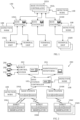
- FIG. 1 of the drawings illustrates a communication system 100 that may be configured to provide communications between one or more base station controllers 102A to 102L, one or more base stations 104A to 104M and/or one or more network connected devices or terminal units 106A to 106N.
- the base station controllers 102A to 102L may be implemented for example as a network manager for managing communications in a network environment.
- the elements that may be transmitting or receiving data may generically be referenced as devices, which would include at least the terminal units 106A to 106N, base stations 104A to 104M and the base station controllers 102A to 102L but may also be other elements capable of transmitting or receiving data.
- Some embodiments of the invention include detection nodes 108, described below.
- the communication system 100 may be operable such that terminal units 106A to 106N are able to communicate with one another in addition to communicating with one or more centralized systems, including the base stations 104A to 104M and/or the base station controllers 102A to 102L, and/or one or more network managers.
- the system 100 may be operable to provide communications in a point-to-point arrangement, a point-to-multipoint arrangement, and/or a multipoint-to-multipoint arrangement.
- the communication links in the system 100 are not necessarily established in a hierarchical fashion. Communication links may be formed also between devices that perform similar functions, such as between terminal units 106A to 106N, base stations 104A to 104M or base station controllers 102A to 102L. Certain communication links may be implemented using various wired technologies, in addition to links implemented using wireless communication technologies.
- the wireless links in the system 100 may operate through a variety of transmission media.
- the wireless links may communicate using, for example, electromagnetic waves (radio waves, microwaves, infrared, light, laser, lidar, terahertz radiation), sound, or any transmission medium that may be utilized for wireless communications.
- the system may further be operable in more than one transmission media.
- the communication system 100 may be configured to enable communications by provisioning and allocating one or more communication links for communications by the devices.
- the communication system 100 may also be configured to utilize various technologies and/or arrangements to use the limited spectrum bandwidth more efficiently.
- Each link may be provisioned based on various factors, such as using various frequency ranges, timeslots and tiles.
- Each of these links may have the same or different characteristics, such as bandwidth, latency, traffic congestion or modulation scheme.
- Frequencies used by various communication links may or may not be adjacent to one another, depending on the particular embodiment and configuration.
- the frequency ranges may be selected and the system 100 may operate such that the system operates within various standards and may co-exist with other users of communications frequencies, such as television broadcasters, mobile telephones and radar. These standards may vary from jurisdiction to jurisdiction. There may be regulatory requirements to co-exist "politely" with other users of spectrum.
- the communication links may be used for transmitting or receiving information data and control data, and one or more communication links may also be utilized for emergency, monitoring or diagnostic purposes.
- the wireless communication system 100 may be configured to adapt to interference or other issues by, for example, changing communication channels for communications, resizing communication links, applying filters, employing error checking, employing spatial/frequency techniques and in particular by changing channel parameters including frequencies in response to detection of extraneous received signals.
- the wireless communication system 100 is described herein with frequent reference to radar signals as extraneous received signals but it will be appreciated that the system 100 can also be used to detect and adapt to other extraneous received signals.
- the communication links may be allocated, repurposed and/or re-sized and the system 100 may benefit from increased flexibility in ease of use and deployment, and when scaling up/down existing deployments.
- the capacity of the system may be altered by altering tile characteristics, such as pilots, forward error correction, for various reasons, such as taking into consideration the characteristics (physical and spectral) of the environment.
- the system may be designed for indoor and/or outdoor use.
- FIG. 2 illustrates an example of application of the wireless communication system 100 to a warehouse facility 200 with one or more robots including the terminal units 106A to 106N for placing objects in and picking objects from the bins. Movements of the robots may be enabled across various paths, some of which may intersect.
- the warehouse facility 200 may include bins arranged for example in a grid-like structure, where the robots move within the warehouse facility to perform various tasks.
- Other non-robot devices may also be terminal units, for example, a human could carry around a terminal unit for communication.
- Additional detection nodes 108 may provide reports relating to detection of extraneous received signals to base stations 104A to 104M, as shown in FIG. 2 , or to the base station controllers 102A to 102L, over suitable wired or wireless links.
- the communication system in the warehouse facility 200 may be configured to provide a bandwidth efficient radio control system for robots/terminal units that operate on an X, Y grid of approximate 60 x 120 meters, for example. Each grid can have many hundreds of robots and there can be several grids in a warehouse.
- the system is configured using base stations 104A to 104M providing point to multipoint communications using Time Division Duplex (TDD) to separate the uplink and downlink and Time Division Multiplex (TDM) and Frequency Division Multiplex (FDM) to subdivide the time frequency space to allow for a number of narrow bandwidth connections between the base stations and the terminals/robots.
- TDD Time Division Duplex
- TDM Time Division Multiplex
- FDM Frequency Division Multiplex
- the transmitters of the base stations may use additional puncturing in the transmit (Tx) sub frame (erasing of Tx bits to enable listening) for detection of radar signals, noise or interference from other sources, by listening for and detecting energy in inactive tiles in the Tx sub-frame.
- the warehouse facility 200 may include a robot control system 202, a maintenance/monitoring system 204, one or more warehouse management systems (WMS) 206, order management systems 208 and one or more information management systems 210.
- the wireless communication links of the warehouse facility 200 may be based on broadband Wi-Fi, which enables real-time or near real-time wireless communication between the base stations 104A to 104M and the terminal units 106A to 106N of the robots.
- the warehouse management system 206 may contain information such as items required for an order, stock keeping units in the warehouse, expected/predicted orders, items missing on orders, when an order is to be loaded on a transporter, expiry dates on items, what items are in which container, and whether items are fragile or big and bulky, for example.
- the robot control system 202 may be configured to control the navigation/routing of robots, including moving from one location to another, collision avoidance, optimization of movement paths and control of activities to be performed, for example.
- the robot control system 202 may be configured to send control messages to robots, receive one or more updates from robots, and otherwise communicate with robots using a real or near-real time protocol through their terminal units 106A to 106N, the base stations 104A to 104M and the base station controllers 102A to 102L.
- the robot control system 202 may receive information indicating robot location and availability from the base station controller 102.
- the maintenance/monitoring system (MMS) 204 may be configured to provide monitoring functions, including receiving alerts from the robots/terminal units 106A to 106N and the base stations 104A to 104M and establishing connections to query the robots.
- the MMS 204 may also provide an interface for the configuration of monitoring functions.
- the MMS 204 may interact with the Robot Control System 202 to indicate when certain robots should be recalled, or determine when an issue with the system has arisen, such as many clearances having been withdrawn, many paths having failed to resolve, or a number of idle robots beyond a predetermined number.
- the robots/terminal units 106A to 106N may include respective real-time controllers (RTC), digital signal processors (DSP) and radio modules, as well as one or more manipulators for handling objects.
- the base stations 104A to 104M may include respective central processor units (CPU), DSP and radio modules.
- the base station controllers 102A to 102L may store master routing information to map the robots, the base stations, and the grids, and are configured to manage dynamic frequency selection and frequency allocation of the base stations 104A to 104M.
- Dynamic frequency selection in some embodiments, may be handled by specific receiver elements, described in more detail below, that monitor channels for detecting extraneous received signals, and may be part of a dedicated DFS radio frequency chain.
- the base stations 104A to 104M may be organized as a pool of base stations, which may then be configured to be active, on standby or to monitor the system. Messages may be routed through the communication system 100 to and from the robots/terminal units 106A to 106N, such as those falling under IEEE wireless standard 802.11, and through fixed links with wired communication, for example Ethernet, to and from the base station controllers 102A to 102L and from any detection nodes 108.
- the base stations 104A to 104M can each signal to the robots/terminal units 106A to 106N linked to that base station to cease transmission prior to the base station ceasing its own transmission, to change the operating frequency as instructed by the base station controllers 102A to 102L, and inform the robot/terminal units 106A to 106N of a frequency or other channel change using a broadcast communication link.
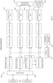
- Fig. 3 illustrates an example of a base station 300 in the wireless communication system 100, which may have several similar bases stations.
- the system illustrated is a point to multipoint communications system operating in the unlicensed 5470 to 5725 MHz frequency band, but it will be appreciated that other frequency bands may be used and that a system can use two or more non-adjacent frequency bands.
- the base station 300 uses a 10MHz bandwidth communication link allocation and may be configured to connect in a time division duplex (TDD) and/or a time division multiple access (TDMA) technique to a number of terminal units in a real or near real time manner.
- TDD time division duplex
- TDMA time division multiple access
- the base station 300 has a communication module for transmitting and receiving data.
- the communication module comprises two in-channel receiver chains 302 and 304 operating in parallel for receiving data signals over the operational communication links from antennae 306 and a switching module 308, a transmitter chain 310 and an out-of-channel receiver chain 312 for monitoring signals received in channels different from the channels used by the receiver chains 302 and 304.
- a base station may comprise only a single in-channel receiver chain respectively, but the use of two in-channel receiver chains 302 and 304 in the base station, as shown, reduces the statistical risk of the antennas for both RF chains being both located in a local null caused by destructive interference in the multipath environment of a warehouse.
- the receiver chains 302, 304 and 312 are dual conversion super heterodyne receiver elements having a front end amplifier and filter with a RF frequency of 5470 to 5725MHz, a first down conversion to IF frequency and a final down conversion to in-phase and quadrature (IQ) baseband.
- the transmitter chain 310 has similar up conversion elements for generating the transmitter signal.
- the communication module of the base station 300 includes a channel allocation memory 314 that stores parameters defining the channels used by the different chains of the communication module, as well as target channel parameters for alternative channels allocated by the base station controller 102, enabling a rapid change of channel in the case of detection of an extraneous received signal in the operating channel, or of a change of operational channel allocation.
- the channel allocation memory 314 pilots local oscillators 316 supplying the down conversion and up conversion frequencies.
- the communication module of the base station 300 includes an in-channel detector 318 that analyses signals from the receiver chains 302 and 304 received over operational communication links for detecting extraneous received signals.
- An out-of-channel detector 320 analyses baseband signals received by the out-of-channel receiver chain 312 in channels different from the operating channels used by the receiver chains 302 and 304 for detecting extraneous received signals.
- the detectors 318 and 320 are used for detecting radar signals and ensuring compliance with the regulations by dynamic frequency selection (DFS), and changing the channel parameters including the frequencies to avoid the interference with the radar transmissions.
- the out-of-channel detector 320 performs channel availability check (CAC) procedures on the possibly available alternative channels.
- CAC channel availability check
- the detectors 318 and 320 may also be used to detect interference by noise, or by communication signals from adjacent devices and avoid the interference with the reception of the wireless communication system 100 and may perform clear channel assessment procedures on the operating and possibly available alternative channels.
- the detectors 318 and 320 send signals to the base station controller 102 forming reports of detection of extraneous received signals.
- the reports also include reports of channels that have successfully passed the channel availability check and clear channel assessment procedures.
- Channel availability check and clear channel assessment procedures are specified in certain standards and it will be appreciated that embodiments of the invention may use procedures specified in the standards, and future evolutions of the standards, and may use other procedures that are noncompliant.
- the base station 300 as master unit controls the channel parameters for the communication links with linked terminal units as slave units.
- the terminal units 106A to 106N may have receiver chains, transmitter chains, antennae and switching elements similar to the corresponding elements of the base station 300, the channel parameters used by the terminal units being set by the linked base station 300.
- the terminal units 106A to 106N may also detect extraneous received signals and may also have an out-of-channel receiver chain, an in-channel detector that analyses signals from the operational receiver chains and an out-of-channel detector that analyses signals received in other channels for detecting extraneous received signals, detection being reported to the base station controller 102 through the linked base station 300.
- Figs. 4 to 6 illustrate, by way of example, a process ensuring compliance with regulations governing avoidance of radar signals by dynamic frequency selection (DFS) in the wireless communication system 100.
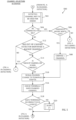
- Fig. 4 illustrates an example of a procedure 400 of in-channel detection of radar signals
- Fig. 5 illustrates an example of a radar avoidance procedure 500 of changing the channel parameters including the frequencies used to avoid the interference with the radar transmissions
- Fig. 6 illustrates an example of a procedure 600 of out-of-channel detection of radar signals.
- DFS dynamic frequency selection
- the operation of the wireless communication system is described below with reference to field operation, the test operation being similar, apart from differences caused by the specified test configurations and conditions.
- the channels are divided into two sets: set1 is channel numbers 0 to 11 and 18 to 23 and set2 is channel numbers 12 to 17 .
- the operational requirements for set2 are more stringent than for set1.
- CAC channel availability check
- the out-of-channel detector 320 monitors all channels other than the operating channel on a cyclical basis, starting with channels only from set1, and for a minimum duration of 6 minutes for each channel. After checking set1 channels, if the out-of-channel detector 320 monitors set2 channels it checks each set2 channel for a minimum duration of 1 hour.
- the base station controller (BSC) 102 receives signals reporting the results of the CACs from all the base stations, including any results from the terminal units.
- the BSC 102 registers all channels that have been checked for more than the minimum duration (white list) and without any BS detecting a radar signal.
- the BSC 102 also registers all channels that any BS has detected radar in (black list).
- the BSC 102 allocates channels only from the white list to the base stations for the operating communication links and also for the channels to be monitored by the out-of-channel detector 320 in this example.
- the BS 104A to 104M select, at least in part autonomously, the channels to be monitored by the out-of-channel detector 320.
- Detection of radar in any channel in the white list transfers the channel immediately to the black list and the BSC 102 allocates a change to a new channel from the white list to any BS using the incriminated channel.
- the allocations of channels are registered in the channel allocation memory 314 of each base station, for immediate use without needing to perform the CAC procedure.
- the base stations cease transmitting when radar is detected if no new channel is allocated by the BSC 102 as available or stored in its white list.
- the regulations also provide for base station operation when not connected to a base station controller, in which circumstances the base stations keep their own white lists and black lists, with updating by communication directly between the different base stations in another embodiment of the invention.
- the process 400 of in-channel detection of radar signals starts at 402 with power up of the base station.
- the process 400 branches and if the communication system 100 is being tested the system follows the procedure 406 set out in the relevant regulations for testing.
- the process 400 branches again at 408 and is described below if the system is operating according to EU regulations, the process 400 following generally similar procedures 410 with different parameters for other regulations.
- the base stations start the channel availability check (CAC) procedure by setting thresholds for minimum levels of detection of radar signals, with the BS transmitters OFF, the thresholds being set by the BSC 102, when the BSs are connected to the BSC, in normal field operation.
- the in-channel detectors 318 perform CAC on a channel allocated by the BSC 102 from channel set1, the BSC 102 removing that channel from the list of channels from set1 that can be allocated as the operating channel.
- the in-channel detectors 318 of the BSs check the channel for radar signals at 416 during 60 secs minimum.
- the detector sends a report signal to the BSC 102 and the BSC 102 includes the channel at 420 in the black list not to be used for at least 30 minutes by any of the BSs or the terminal units in the wireless communication system 100.
- the process branches and if there are any channels left in set1, the BSC 102 allocates another channel to be checked and the process 400 reverts to performing CAC on the new channel at 414. If there are no channels left in set1, the process 400 raises an alert at 424, to bring to the attention of the human operators / support staff of the system that there is an issue, and then checks set2 channels.
- the in-channel detectors 318 perform CAC on a channel allocated by the BSC 102 from channel set2, the BSC 102 removing that channel from the list of channels from set2 that can be allocated as the operating channel.
- the in-channel detectors 318 of the BSs check the channel for radar signals at 428 during 600 secs minimum.
- the detector sends a report signal to the BSC 102 and the BSC 102 includes the channel at 432 in the black list not to be used for at least 30 minutes by any of the BSs or the terminal units in the wireless communication system 100.
- the process branches and if there are any channels left in set2, the BSC 102 allocates another channel to be checked and the process 400 reverts to performing CAC on the new channel at 426. If there are no channels left in set2, the process 400 raises an alert at 436.
- the process 400 branches at 438: if there are any channels that were on the black list that have completed a duration of 30 mins without further detection of radar signals, they are re-instated in set1 or set2 at 440 and the process 400 reverts to the CAC procedure at 412.
- the base station that has been prevented from transmitting on its operating channel reverts to the CAC procedure at 412 without transmitting until a channel has become available and it has been allocated a channel from the white list.
- the detector sends a report signal to the BSC 102 and the BSC 102 allocates the channel to the base station and linked terminal units as new operating channel and at 442 the base station and linked terminal units tune their transmitters and receivers to the new channel parameters.
- the reaction of the wireless communication system 100 to switch channels must conform to maximum timings specified in the relevant regulations.
- the out-of-channel detector 320 starts monitoring all channels other than the operating channel on a cyclical basis, according to the process 600 described below with reference to Fig. 6 .
- the in-channel detector 318 continues to monitor continuously for radar signal detection at 446 and can monitor for radar signals even in slots where it is transmitting itself, during tiles which it is not using. If energy is found at 448 corresponding to a radar signal, the detector sends a report signal to the BSC 102 and the wireless communication system 100 starts the radar avoidance procedure 500 illustrated in Fig. 5 .
- the radar avoidance procedure 500 starts by the base stations and the BSC 102 including the channel at 502 in the black list not to be used for at least 30 minutes by any of the BSs or the terminal units in the wireless communication system 100. This is performed by the BSC 102 if at 504 the connections of the base stations to the BSC 102 are established. However certain regulations specify test procedures with the base stations disconnected from the BSC. If at 504 the base stations are connected to the BSC 102, and if at 506 a backup channel is available on the white list, the BSC 102 chooses at 508 a channel to allocate to the base station at 510. If at 506 no backup channel is available on the white list, the base station that has been prevented from transmitting on its operating channel reverts to the CAC procedure at 412 ( Fig. 4 ) without transmitting until a channel has become available.
- the procedure relies on white and black lists registered in the base stations themselves on detection by themselves or by linked terminal units or by other base stations through connections directly between the base stations. If at 512 the out-of-channel detectors 320 have identified no backup channel available, or if at 514 a backup channel would be available but is still on 30 min. timeout, the base station that has been prevented from transmitting on its operating channel reverts to the CAC procedure at 412 without transmitting until a channel has become available. If a channel is allocated to the base station at 510, the base station signals to the linked terminal units to change channel and then stops its transmission.
- the base station checks whether the linked terminal units have reconnected to the new channel within less than 10 secs. If so, at 518 the base station and linked terminal units tune their transmitters and receivers to the new channel parameters at 442 ( Fig. 4 ). If at 516 one or more linked terminal units have not reconnected to the new channel within less than 10 secs, an alert is raised at 520. The alert is raised to ease operation of the system and to make the operations staff aware of an issue. Now that the BS has moved to a new channel, the terminal units will not transmit until they have re-tuned their receivers and successfully decoded broadcast traffic from the BS, sometimes referred to as listen before speak.
- the detector sends a report signal to the BSC 102 and the BSC 102 includes the channel at 614 in the black list not to be used for at least 30 minutes by any of the BSs or the terminal units in the wireless communication system 100 and the procedure 600 reverts to 602 with the BSC 102 allocating a channel. If at 616 the channel monitored by the out-of-channel detector 320 is from set1, and if the channel has been monitored for 6 mins, the detector 320 sends a report signal to the BSC 102 and the BSC 102 includes the channel at 62 0 in the white list.
- the detector 320 sends a report signal to the BSC 102 and the BSC 102 includes the channel at 620 in the white list. Otherwise, the detector 320 continues monitoring the channel at 610.
- the computer program may be stored internally on computer readable storage medium or transmitted to the computer system via a computer readable transmission medium. All or some of the computer program may be provided on computer readable media permanently, removably or remotely coupled to an information processing system.
- the computer readable media may include, for example and without limitation, any number of the following: magnetic storage media including disk and tape storage media; optical storage media such as compact disk media (e.g., CD-ROM, CD-R, etc.) and digital video disk storage media; non-volatile memory storage media including semiconductor-based memory units such as FLASH memory, EEPROM, EPROM, ROM; ferromagnetic digital memories; MRAM; volatile storage media including registers, buffers or caches, main memory, RAM, etc.; and data transmission media including computer networks, point-to-point telecommunication equipment, and carrier wave transmission media, just to name a few.
- a computer process typically includes an executing (running) program or portion of a program, current program values and state information, and the resources used by the operating system to manage the execution of the process.
- An operating system is the software that manages the sharing of the resources of a computer and provides programmers with an interface used to access those resources.
- An operating system processes system data and user input, and responds by allocating and managing tasks and internal system resources as a service to users and programs of the system.
- the computer system may for instance include at least one processing unit, associated memory and a number of input/output (I/O) devices.
- I/O input/output
- the computer system processes information according to the computer program and produces resultant output information via I/O devices.
- connections as discussed herein may be any type of connection suitable to transfer signals from or to the respective nodes, units or devices, for example via intermediate devices. Accordingly, unless implied or stated otherwise, the connections may for example be direct connections or indirect connections.
- the connections may be illustrated or described in reference to being a single connection, a plurality of connections, unidirectional connections, or bidirectional connections. However, different embodiments may vary the implementation of the connections. For example, separate unidirectional connections may be used rather than bidirectional connections and vice versa.
- plurality of connections may be replaced with a single connections that transfers multiple signals serially or in a time multiplexed manner. Likewise, single connections carrying multiple signals may be separated out into various different connections carrying subsets of these signals. Therefore, many options exist for transferring signals.
- logic blocks are merely illustrative and that alternative embodiments may merge logic blocks or circuit elements or impose an alternate decomposition of functionality upon various logic blocks or circuit elements.
- architectures depicted herein are merely exemplary, and that in fact many other architectures can be implemented which achieve the same functionality.
- the invention is not limited to physical devices or units implemented in nonprogrammable hardware but can also be applied in programmable devices or units able to perform the desired device functions by operating in accordance with suitable program code, such as mainframes, minicomputers, servers, workstations, personal computers, notepads, personal digital assistants, electronic games, automotive and other embedded systems, cell phones and various other wireless devices, commonly denoted in this application as 'computer systems'.
- suitable program code such as mainframes, minicomputers, servers, workstations, personal computers, notepads, personal digital assistants, electronic games, automotive and other embedded systems, cell phones and various other wireless devices, commonly denoted in this application as 'computer systems'.
- any reference signs placed between parentheses shall not be construed as limiting the claim.
- the word 'comprising' does not exclude the presence of other elements or steps then those listed in a claim.
- the terms "a” or "an,” as used herein, are defined as one, or more than one.
Landscapes
- Engineering & Computer Science (AREA)
- Computer Networks & Wireless Communication (AREA)
- Signal Processing (AREA)
- Radar, Positioning & Navigation (AREA)
- Remote Sensing (AREA)
- Quality & Reliability (AREA)
- Physics & Mathematics (AREA)
- General Physics & Mathematics (AREA)
- Mobile Radio Communication Systems (AREA)
- Radio Transmission System (AREA)
Claims (13)
- Drahtloses Kommunikationssystem (100), das umfasst:eine Vielzahl von Basisstationen (104);eine Vielzahl von entfernt angeordneten Endgeräteeinheiten (106);wobei die Basisstationen (104) und die entfernt angeordneten Endgeräteeinheiten (106) jeweilige Kommunikationsmodule umfassen, die konfiguriert sind, um Daten über betriebsbereite drahtlose Kommunikationskopplungen zwischen zumindest den Basisstationen und den Endgeräteeinheiten zu senden und zu empfangen, wobei die Kommunikationsmodule jeweilige Empfängerelemente im Kanal für Signale enthalten, die über die betriebsbereiten Kommunikationskopplungen empfangen werden; undmindestens ein Basisstation-Steuergerät (102), das konfiguriert ist, um Kanalparameter zu steuern, die von den Basisstationen (104) für die jeweiligen Kommunikationskopplungen verwendet werden, wobei die Kanalparameter Zuweisungen von Frequenzen zur Verwendung in den Kommunikationskopplungen enthalten;dadurch gekennzeichnet, dass:zumindest mehrere der Basisstationen (104) jeweilige Detektoren (318) im Kanal und Detektoren (320) außerhalb des Kanals enthalten, die konfiguriert sind, um von außen empfangene Signale zu erfassen;die Detektoren (318) im Kanal konfiguriert sind, um Signale von den Kommunikationsmodulen in den Basisstationen zu analysieren, welche über betriebsbereite Kommunikationskopplungen empfangen werden, und die Detektoren (320) außerhalb des Kanals jeweilige Empfängerelemente (312) außerhalb des Kanals enthalten und konfiguriert sind, um möglicherweise verfügbare Kanäle alternativ zu den jeweiligen betriebsbereiten Kommunikationskopplungen für eine minimale Dauer von Kanalverfügbarkeit-Prüfprozeduren zu überwachen, um Radarsignale als die von außen empfangenen Signale zu erfassen;das Basisstation-Steuergerät (102) konfiguriert ist, um Berichte zur Erfassung von Signalen, die von außen empfangen werden, von den Detektoren (318) im Kanal und den Detektoren (320) außerhalb des Kanals zu empfangen, um zu registrieren, ob Kanäle für Kommunikationskopplungen verfügbar sind oder nicht, und um den Basisstationen (104) jeweilige Zielkanalfrequenzen zuzuweisen, die für betriebsbereite und alternative Kommunikationskopplungen zur Verfügung stehen;die Basisstationen (104) konfiguriert sind, um die jeweiligen zugewiesenen Zielkanalfrequenzen zu speichern, die erfolgreich dahingehend geprüft wurden, dass sie für betriebsbereite und alternative Kommunikationskopplungen zur Verfügung stehen; unddie Basisstationen (104) konfiguriert sind, um Kanalparameter, die für die jeweiligen betriebsbereiten Kommunikationskopplungen verwendet werden, auf die zugewiesenen gespeicherten Zielkanalfrequenzen zu verändern, bei denen erfolgreich geprüft wurde, dass sie für alternative Kommunikationskopplungen zur Verfügung stehen, ohne eine weitere Verfügbarkeitsprüfung der alternativen Kommunikationskopplungen.
- Drahtloses Kommunikationssystem nach Anspruch 1, wobei die Basisstationen (104) konfiguriert sind, um in Ansprechen auf das Erfassen von Radarsignalen im Kanal, die von außen empfangen werden, Kanalparameter für die betriebsbereiten Kommunikationskopplungen auf die gespeicherten Kanalfrequenzen für die alternativen Kommunikationskopplungen zu verändern.
- Drahtloses Kommunikationssystem nach Anspruch 2, wobei die Basisstationen (104) konfiguriert sind, um Kanalparameter für die betriebsbereiten Kommunikationskopplungen in Ansprechen darauf zu verändern, dass der jeweilige Detektor (318) im Kanal von außen empfangene Signale erfasst, und darauf, dass das Basisstation-Steuergerät (102) Frequenzzuweisungen für die jeweiligen Basisstationen als Funktion eines Berichts von einer anderen Basisstation verändert.
- Drahtloses Kommunikationssystem nach Anspruch 2 oder 3, wobei die Basisstationen (104) konfiguriert sind, um dynamische Frequenzauswahltechniken zu verwenden, um Kanalparameter für die betriebsbereiten Kommunikationskopplungen zu verändern.
- Drahtloses Kommunikationssystem nach Anspruch 4, wobei die Detektoren (318) im Kanal und die Detektoren (320) außerhalb des Kanals konfiguriert sind, um einen Empfang von Radarsignalen als die von außen empfangenen Signale zu erfassen und die dynamischen Frequenzauswahltechniken zur Radarerfassung und Vermeidung verwendet werden.
- Drahtloses Kommunikationssystem nach einem der vorhergehenden Ansprüche, wobei die Basisstationen (104) als Mastereinheiten konfiguriert sind, um die Kanalparameter für die Kommunikationskopplungen mit gekoppelten Endgeräteeinheiten (106) als Slave-Einheiten zu steuern.
- Drahtloses Kommunikationssystem nach einem der vorhergehenden Ansprüche, wobei die Detektoren (320) außerhalb des Kanals konfiguriert sind, um Kanalverfügbarkeit-Prüfprozeduren an den möglicherweise verfügbaren alternativen Kanälen durchzuführen, und die Berichte zur Erfassung von von außen empfangenen Signalen Berichte von Kanälen enthalten, welche die Kanalverfügbarkeit-Prüfprozeduren erfolgreich bestanden haben.
- Drahtloses Kommunikationssystem nach einem der vorhergehenden Ansprüche, und ferner mit mindestens einem Erfassungsknoten (108), der mindestens ein Empfängerelement aufweist, das konfiguriert ist, um betriebsbereite und/oder möglicherweise alternative verfügbare Kommunikationskopplungskanäle der Basisstationen (104) zu überwachen, um von außen empfangene Signale zu erfassen, und um Berichte über die Verfügbarkeit der Kanäle die es für Kommunikationskopplungen überwacht, für das Basisstation-Steuergerät (102) bereitzustellen.
- Drahtloses Kommunikationssystem nach Anspruch 8, wobei der Erfassungsknoten (108) konfiguriert ist, um die Berichte an das Basisstation-Steuergerät (102) zu liefern, welches konfiguriert ist, um die jeweiligen zugewiesenen Zielkanalfrequenzen bereitzustellen, deren Verfügbarkeit für die Basisstationen (104) erfolgreich geprüft wurde.
- Drahtloses Kommunikationssystem nach Anspruch 8 oder 9, wobei der Erfassungsknoten (108) konfiguriert ist, um in einem Betriebsmodus wie eine Basisstation (104) zu funktionieren, die mit Endgeräteeinheiten (106) kommuniziert, und um in einem anderen Betriebsmodus zu funktionieren, um mögliche alternative verfügbare Kommunikationskopplungskanäle der Basisstationen für die Basisstationen (104) zu überwachen, wenn er selbst nicht als Basisstation arbeitet.
- Drahtloses Kommunikationssystem nach einem der vorhergehenden Ansprüche, wobei die Endgeräteeinheiten (106) mobil sind, und das System ein Routing-Steuergerät (202) enthält, um Navigationsinformationen über die drahtlosen Kommunikationskopplungen für die Endgeräteeinheiten (106) bereitzustellen.
- Lagerhausanlage, die eine Struktur von Behältern und ein drahtloses Kommunikationssystem nach Anspruch 11 umfasst, wobei das Routing-Steuergerät (202) konfiguriert ist, um die mobilen Endgeräteeinheiten (106) zu steuern, um Operationen mit den Behältern durchzuführen.
- Lagerhausanlage nach Anspruch 12 und mit einer Vielzahl von Robotern, die konfiguriert sind, um sich entlang sich schneidender Wege relativ zu der Struktur zu bewegen, um Operationen mit den Behältern durchzuführen, wobei die Roboter jeweilige der Endgeräteeinheiten (106) enthalten und das Routing-Steuergerät (202) konfiguriert ist, um mit den Robotern zur Steuerung der Operationen zu kommunizieren.
Priority Applications (1)
| Application Number | Priority Date | Filing Date | Title |
|---|---|---|---|
| EP23164147.3A EP4221420B1 (de) | 2017-01-08 | 2017-12-22 | Drahtloskommunikationssystem mit detektoren für empfangene fremdsignale |
Applications Claiming Priority (2)
| Application Number | Priority Date | Filing Date | Title |
|---|---|---|---|
| GB1700286.6A GB2558587B (en) | 2017-01-08 | 2017-01-08 | Wireless communication system with detectors for extraneous received signals |
| PCT/EP2017/084485 WO2018127437A1 (en) | 2017-01-08 | 2017-12-22 | Wireless communication system with detectors for extraneous received signals |
Related Child Applications (2)
| Application Number | Title | Priority Date | Filing Date |
|---|---|---|---|
| EP23164147.3A Division-Into EP4221420B1 (de) | 2017-01-08 | 2017-12-22 | Drahtloskommunikationssystem mit detektoren für empfangene fremdsignale |
| EP23164147.3A Division EP4221420B1 (de) | 2017-01-08 | 2017-12-22 | Drahtloskommunikationssystem mit detektoren für empfangene fremdsignale |
Publications (2)
| Publication Number | Publication Date |
|---|---|
| EP3566526A1 EP3566526A1 (de) | 2019-11-13 |
| EP3566526B1 true EP3566526B1 (de) | 2023-08-09 |
Family
ID=58463971
Family Applications (2)
| Application Number | Title | Priority Date | Filing Date |
|---|---|---|---|
| EP17818590.6A Active EP3566526B1 (de) | 2017-01-08 | 2017-12-22 | Drahtloskommunikationssystem mit detektoren für empfangene fremdsignale |
| EP23164147.3A Active EP4221420B1 (de) | 2017-01-08 | 2017-12-22 | Drahtloskommunikationssystem mit detektoren für empfangene fremdsignale |
Family Applications After (1)
| Application Number | Title | Priority Date | Filing Date |
|---|---|---|---|
| EP23164147.3A Active EP4221420B1 (de) | 2017-01-08 | 2017-12-22 | Drahtloskommunikationssystem mit detektoren für empfangene fremdsignale |
Country Status (9)
| Country | Link |
|---|---|
| US (3) | US11063687B2 (de) |
| EP (2) | EP3566526B1 (de) |
| CN (1) | CN110235498B (de) |
| AU (2) | AU2017390945B2 (de) |
| CA (1) | CA3049151C (de) |
| ES (2) | ES2962772T3 (de) |
| GB (1) | GB2558587B (de) |
| PL (2) | PL3566526T3 (de) |
| WO (1) | WO2018127437A1 (de) |
Families Citing this family (10)
| Publication number | Priority date | Publication date | Assignee | Title |
|---|---|---|---|---|
| GB2558587B (en) * | 2017-01-08 | 2020-12-09 | Ocado Innovation Ltd | Wireless communication system with detectors for extraneous received signals |
| TWI726208B (zh) * | 2018-04-27 | 2021-05-01 | 奇邑科技股份有限公司 | 根據訊號掃描結果調整通道的通訊方法與通訊系統 |
| US11283475B1 (en) * | 2019-03-14 | 2022-03-22 | Amazon Technologies, Inc. | Radio interference detection and dynamic channel bandwidth management |
| JP7423903B2 (ja) * | 2019-04-25 | 2024-01-30 | 株式会社ソシオネクスト | レーダ装置の制御方法及びレーダ装置 |
| JP7705848B2 (ja) * | 2020-04-24 | 2025-07-10 | パナソニック インテレクチュアル プロパティ コーポレーション オブ アメリカ | 通信装置及びセンシング方法 |
| CN112105070B (zh) * | 2020-08-31 | 2022-05-27 | 新华三技术有限公司 | 一种信道切换方法及装置 |
| GB202203209D0 (en) | 2022-03-08 | 2022-04-20 | Ocado Innovation Ltd | Communications system |
| GB202203211D0 (en) | 2022-03-08 | 2022-04-20 | Ocado Innovation Ltd | Communication system |
| GB2624157A (en) | 2022-11-03 | 2024-05-15 | Ocado Innovation Ltd | Communications system |
| JP2025541597A (ja) | 2022-11-03 | 2025-12-22 | オカド・イノベーション・リミテッド | 荷役ハンドラを含むセキュアな保管システム |
Family Cites Families (20)
| Publication number | Priority date | Publication date | Assignee | Title |
|---|---|---|---|---|
| US5148548A (en) * | 1989-12-19 | 1992-09-15 | Northern Telecom Limited | Method of monitoring cellular radio channels to avoid adjacent and co-channel interference |
| JP2661533B2 (ja) * | 1993-12-27 | 1997-10-08 | 日本電気株式会社 | 移動通信システムのチャネル割当方式 |
| US6377548B1 (en) * | 1997-10-14 | 2002-04-23 | Lucent Technologies Inc. | Method for admitting new connections based on measured quantities in a multiple access system for communications networks |
| US6741839B1 (en) * | 1999-09-16 | 2004-05-25 | Samsung Electronics Co., Ltd. | System and method for monitoring adjacent channel power in a wireless base station |
| US6418317B1 (en) * | 1999-12-01 | 2002-07-09 | Telefonaktiebolaget Lm Ericsson (Publ) | Method and system for managing frequencies allocated to a base station |
| WO2003001742A1 (en) * | 2001-06-25 | 2003-01-03 | Commprize Ventures Limited | Method and system for detection of and dynamic adaptation to radio interference in a shared wireless communications environment |
| EP1443706A1 (de) * | 2003-01-28 | 2004-08-04 | Sony International (Europe) GmbH | Verfahren und Vorrichtung zum Erfassen von Radar-Frequenzband-Interferenzen in einem Netzwerk mit primären und sekundären Benutzern |
| US6870815B2 (en) | 2003-01-30 | 2005-03-22 | Atheros Communications, Inc. | Methods for implementing a dynamic frequency selection (DFS) and a temporary channel selection feature for WLAN devices |
| EP2533594A3 (de) | 2004-03-05 | 2013-02-27 | NTT DoCoMo, Inc. | Frequenzkanalzuweisungssystem, Basisstation, Steuerungsstation, gemeinsame Steuerungsvorrichtung zwischen Systemen, Frequenzkanalzuweisungsverfahren und Steuerungsverfahren |
| US20050215266A1 (en) * | 2004-03-26 | 2005-09-29 | Intel Corporation | Wireless network dynamic frequency selection |
| JP2006197559A (ja) * | 2004-12-17 | 2006-07-27 | Matsushita Electric Ind Co Ltd | 無線通信機及び無線チャネル測定管理端末 |
| US8254922B2 (en) | 2006-10-16 | 2012-08-28 | Stmicroelectronics, Inc. | Zero delay frequency switching with dynamic frequency hopping for cognitive radio based dynamic spectrum access network systems |
| US8687563B2 (en) * | 2007-01-09 | 2014-04-01 | Stmicroelectronics, Inc. | Simultaneous sensing and data transmission |
| WO2011056670A2 (en) * | 2009-10-27 | 2011-05-12 | Quantenna Communications, Inc. | Channel scanning and channel selection in a wireless communication network |
| US9119079B2 (en) | 2012-01-27 | 2015-08-25 | Airties Kablosuz Iletisim San. Ve Dis Tic. A.S. | System and method to avoid interference with radar systems |
| GB201410025D0 (en) | 2014-06-05 | 2014-07-16 | Ocado Ltd | Systems and methods for communication |
| CN105993183B (zh) | 2014-06-30 | 2019-08-13 | 优倍快网络公司 | 用于在无线电网络的配置中使用功能图协助的方法和工具 |
| US9832791B2 (en) * | 2015-08-04 | 2017-11-28 | Network Performance Research Group Llc | Method and apparatus for use of simultaneous multiple channels in the dynamic frequency selection band in wireless networks |
| US9622161B1 (en) | 2015-10-23 | 2017-04-11 | Belden, Inc. | Systems and methods for obtaining available channels for fast channel switching |
| GB2558587B (en) * | 2017-01-08 | 2020-12-09 | Ocado Innovation Ltd | Wireless communication system with detectors for extraneous received signals |
-
2017
- 2017-01-08 GB GB1700286.6A patent/GB2558587B/en active Active
- 2017-12-22 WO PCT/EP2017/084485 patent/WO2018127437A1/en not_active Ceased
- 2017-12-22 US US16/476,505 patent/US11063687B2/en active Active
- 2017-12-22 CN CN201780084438.4A patent/CN110235498B/zh active Active
- 2017-12-22 ES ES17818590T patent/ES2962772T3/es active Active
- 2017-12-22 CA CA3049151A patent/CA3049151C/en active Active
- 2017-12-22 EP EP17818590.6A patent/EP3566526B1/de active Active
- 2017-12-22 EP EP23164147.3A patent/EP4221420B1/de active Active
- 2017-12-22 PL PL17818590.6T patent/PL3566526T3/pl unknown
- 2017-12-22 ES ES23164147T patent/ES3048416T3/es active Active
- 2017-12-22 PL PL23164147.3T patent/PL4221420T3/pl unknown
- 2017-12-22 AU AU2017390945A patent/AU2017390945B2/en active Active
-
2021
- 2021-06-09 US US17/342,939 patent/US11764895B2/en active Active
-
2022
- 2022-02-03 AU AU2022200721A patent/AU2022200721B2/en active Active
-
2023
- 2023-08-07 US US18/366,391 patent/US20230388042A1/en not_active Abandoned
Also Published As
| Publication number | Publication date |
|---|---|
| US20190356408A1 (en) | 2019-11-21 |
| PL3566526T3 (pl) | 2024-02-12 |
| GB2558587A (en) | 2018-07-18 |
| GB201700286D0 (en) | 2017-02-22 |
| AU2022200721B2 (en) | 2023-11-02 |
| CN110235498A (zh) | 2019-09-13 |
| EP4221420C0 (de) | 2025-07-30 |
| WO2018127437A1 (en) | 2018-07-12 |
| CA3049151A1 (en) | 2018-07-12 |
| US20230388042A1 (en) | 2023-11-30 |
| AU2017390945A1 (en) | 2019-07-18 |
| EP3566526A1 (de) | 2019-11-13 |
| PL4221420T3 (pl) | 2025-12-15 |
| EP4221420B1 (de) | 2025-07-30 |
| AU2022200721A1 (en) | 2022-02-24 |
| EP4221420A1 (de) | 2023-08-02 |
| CN110235498B (zh) | 2023-10-27 |
| GB2558587B (en) | 2020-12-09 |
| CA3049151C (en) | 2025-05-06 |
| ES2962772T3 (es) | 2024-03-21 |
| US20210328706A1 (en) | 2021-10-21 |
| US11764895B2 (en) | 2023-09-19 |
| US11063687B2 (en) | 2021-07-13 |
| AU2017390945B2 (en) | 2021-11-04 |
| ES3048416T3 (en) | 2025-12-10 |
Similar Documents
| Publication | Publication Date | Title |
|---|---|---|
| AU2022200721B2 (en) | Wireless communication system with detectors for extraneous received signals | |
| US11622283B2 (en) | Wireless communication system with discrimination between extraneous received signals | |
| EP4133796B1 (de) | Verfahren zur steuerung des zugriffs in luft-boden-netzwerken mit betrieb in einem unlizenzierten spektrum und benutzergerät | |
| GB2580535A (en) | Wireless communication system with detectors for extraneous received signals | |
| CN108307372A (zh) | 一种多路综合处理的短波应急通信系统及方法 | |
| US20250203642A1 (en) | Resource coexistence method and apparatus |
Legal Events
| Date | Code | Title | Description |
|---|---|---|---|
| STAA | Information on the status of an ep patent application or granted ep patent |
Free format text: STATUS: UNKNOWN |
|
| STAA | Information on the status of an ep patent application or granted ep patent |
Free format text: STATUS: THE INTERNATIONAL PUBLICATION HAS BEEN MADE |
|
| PUAI | Public reference made under article 153(3) epc to a published international application that has entered the european phase |
Free format text: ORIGINAL CODE: 0009012 |
|
| STAA | Information on the status of an ep patent application or granted ep patent |
Free format text: STATUS: REQUEST FOR EXAMINATION WAS MADE |
|
| 17P | Request for examination filed |
Effective date: 20190801 |
|
| AK | Designated contracting states |
Kind code of ref document: A1 Designated state(s): AL AT BE BG CH CY CZ DE DK EE ES FI FR GB GR HR HU IE IS IT LI LT LU LV MC MK MT NL NO PL PT RO RS SE SI SK SM TR |
|
| AX | Request for extension of the european patent |
Extension state: BA ME |
|
| DAV | Request for validation of the european patent (deleted) | ||
| DAX | Request for extension of the european patent (deleted) | ||
| STAA | Information on the status of an ep patent application or granted ep patent |
Free format text: STATUS: EXAMINATION IS IN PROGRESS |
|
| 17Q | First examination report despatched |
Effective date: 20201104 |
|
| REG | Reference to a national code |
Ref country code: DE Ref legal event code: R079 Free format text: PREVIOUS MAIN CLASS: H04W0072080000 Ipc: H04W0072542000 Ref country code: DE Ref legal event code: R079 Ref document number: 602017072550 Country of ref document: DE Free format text: PREVIOUS MAIN CLASS: H04W0072080000 Ipc: H04W0072542000 |
|
| GRAP | Despatch of communication of intention to grant a patent |
Free format text: ORIGINAL CODE: EPIDOSNIGR1 |
|
| STAA | Information on the status of an ep patent application or granted ep patent |
Free format text: STATUS: GRANT OF PATENT IS INTENDED |
|
| RIC1 | Information provided on ipc code assigned before grant |
Ipc: H04W 72/541 20230101ALN20230202BHEP Ipc: H04W 28/16 20090101ALN20230202BHEP Ipc: H04W 16/14 20090101ALN20230202BHEP Ipc: H04K 3/00 20060101ALI20230202BHEP Ipc: H04W 72/542 20230101AFI20230202BHEP |
|
| INTG | Intention to grant announced |
Effective date: 20230302 |
|
| GRAS | Grant fee paid |
Free format text: ORIGINAL CODE: EPIDOSNIGR3 |
|
| GRAA | (expected) grant |
Free format text: ORIGINAL CODE: 0009210 |
|
| STAA | Information on the status of an ep patent application or granted ep patent |
Free format text: STATUS: THE PATENT HAS BEEN GRANTED |
|
| AK | Designated contracting states |
Kind code of ref document: B1 Designated state(s): AL AT BE BG CH CY CZ DE DK EE ES FI FR GB GR HR HU IE IS IT LI LT LU LV MC MK MT NL NO PL PT RO RS SE SI SK SM TR |
|
| P01 | Opt-out of the competence of the unified patent court (upc) registered |
Effective date: 20230630 |
|
| REG | Reference to a national code |
Ref country code: GB Ref legal event code: FG4D |
|
| REG | Reference to a national code |
Ref country code: CH Ref legal event code: EP |
|
| REG | Reference to a national code |
Ref country code: DE Ref legal event code: R096 Ref document number: 602017072550 Country of ref document: DE |
|
| REG | Reference to a national code |
Ref country code: IE Ref legal event code: FG4D |
|
| REG | Reference to a national code |
Ref country code: LT Ref legal event code: MG9D |
|
| REG | Reference to a national code |
Ref country code: SE Ref legal event code: TRGR |
|
| REG | Reference to a national code |
Ref country code: NL Ref legal event code: MP Effective date: 20230809 |
|
| REG | Reference to a national code |
Ref country code: NO Ref legal event code: T2 Effective date: 20230809 |
|
| REG | Reference to a national code |
Ref country code: AT Ref legal event code: MK05 Ref document number: 1598985 Country of ref document: AT Kind code of ref document: T Effective date: 20230809 |
|
| PG25 | Lapsed in a contracting state [announced via postgrant information from national office to epo] |
Ref country code: GR Free format text: LAPSE BECAUSE OF FAILURE TO SUBMIT A TRANSLATION OF THE DESCRIPTION OR TO PAY THE FEE WITHIN THE PRESCRIBED TIME-LIMIT Effective date: 20231110 |
|
| PG25 | Lapsed in a contracting state [announced via postgrant information from national office to epo] |
Ref country code: IS Free format text: LAPSE BECAUSE OF FAILURE TO SUBMIT A TRANSLATION OF THE DESCRIPTION OR TO PAY THE FEE WITHIN THE PRESCRIBED TIME-LIMIT Effective date: 20231209 |
|
| PG25 | Lapsed in a contracting state [announced via postgrant information from national office to epo] |
Ref country code: RS Free format text: LAPSE BECAUSE OF FAILURE TO SUBMIT A TRANSLATION OF THE DESCRIPTION OR TO PAY THE FEE WITHIN THE PRESCRIBED TIME-LIMIT Effective date: 20230809 Ref country code: PT Free format text: LAPSE BECAUSE OF FAILURE TO SUBMIT A TRANSLATION OF THE DESCRIPTION OR TO PAY THE FEE WITHIN THE PRESCRIBED TIME-LIMIT Effective date: 20231211 Ref country code: NL Free format text: LAPSE BECAUSE OF FAILURE TO SUBMIT A TRANSLATION OF THE DESCRIPTION OR TO PAY THE FEE WITHIN THE PRESCRIBED TIME-LIMIT Effective date: 20230809 Ref country code: LV Free format text: LAPSE BECAUSE OF FAILURE TO SUBMIT A TRANSLATION OF THE DESCRIPTION OR TO PAY THE FEE WITHIN THE PRESCRIBED TIME-LIMIT Effective date: 20230809 Ref country code: LT Free format text: LAPSE BECAUSE OF FAILURE TO SUBMIT A TRANSLATION OF THE DESCRIPTION OR TO PAY THE FEE WITHIN THE PRESCRIBED TIME-LIMIT Effective date: 20230809 Ref country code: IS Free format text: LAPSE BECAUSE OF FAILURE TO SUBMIT A TRANSLATION OF THE DESCRIPTION OR TO PAY THE FEE WITHIN THE PRESCRIBED TIME-LIMIT Effective date: 20231209 Ref country code: HR Free format text: LAPSE BECAUSE OF FAILURE TO SUBMIT A TRANSLATION OF THE DESCRIPTION OR TO PAY THE FEE WITHIN THE PRESCRIBED TIME-LIMIT Effective date: 20230809 Ref country code: GR Free format text: LAPSE BECAUSE OF FAILURE TO SUBMIT A TRANSLATION OF THE DESCRIPTION OR TO PAY THE FEE WITHIN THE PRESCRIBED TIME-LIMIT Effective date: 20231110 Ref country code: FI Free format text: LAPSE BECAUSE OF FAILURE TO SUBMIT A TRANSLATION OF THE DESCRIPTION OR TO PAY THE FEE WITHIN THE PRESCRIBED TIME-LIMIT Effective date: 20230809 Ref country code: AT Free format text: LAPSE BECAUSE OF FAILURE TO SUBMIT A TRANSLATION OF THE DESCRIPTION OR TO PAY THE FEE WITHIN THE PRESCRIBED TIME-LIMIT Effective date: 20230809 |
|
| REG | Reference to a national code |
Ref country code: ES Ref legal event code: FG2A Ref document number: 2962772 Country of ref document: ES Kind code of ref document: T3 Effective date: 20240321 |
|
| PG25 | Lapsed in a contracting state [announced via postgrant information from national office to epo] |
Ref country code: SM Free format text: LAPSE BECAUSE OF FAILURE TO SUBMIT A TRANSLATION OF THE DESCRIPTION OR TO PAY THE FEE WITHIN THE PRESCRIBED TIME-LIMIT Effective date: 20230809 Ref country code: RO Free format text: LAPSE BECAUSE OF FAILURE TO SUBMIT A TRANSLATION OF THE DESCRIPTION OR TO PAY THE FEE WITHIN THE PRESCRIBED TIME-LIMIT Effective date: 20230809 Ref country code: EE Free format text: LAPSE BECAUSE OF FAILURE TO SUBMIT A TRANSLATION OF THE DESCRIPTION OR TO PAY THE FEE WITHIN THE PRESCRIBED TIME-LIMIT Effective date: 20230809 Ref country code: DK Free format text: LAPSE BECAUSE OF FAILURE TO SUBMIT A TRANSLATION OF THE DESCRIPTION OR TO PAY THE FEE WITHIN THE PRESCRIBED TIME-LIMIT Effective date: 20230809 Ref country code: CZ Free format text: LAPSE BECAUSE OF FAILURE TO SUBMIT A TRANSLATION OF THE DESCRIPTION OR TO PAY THE FEE WITHIN THE PRESCRIBED TIME-LIMIT Effective date: 20230809 Ref country code: SK Free format text: LAPSE BECAUSE OF FAILURE TO SUBMIT A TRANSLATION OF THE DESCRIPTION OR TO PAY THE FEE WITHIN THE PRESCRIBED TIME-LIMIT Effective date: 20230809 |
|
| REG | Reference to a national code |
Ref country code: DE Ref legal event code: R097 Ref document number: 602017072550 Country of ref document: DE |
|
| PG25 | Lapsed in a contracting state [announced via postgrant information from national office to epo] |
Ref country code: IT Free format text: LAPSE BECAUSE OF FAILURE TO SUBMIT A TRANSLATION OF THE DESCRIPTION OR TO PAY THE FEE WITHIN THE PRESCRIBED TIME-LIMIT Effective date: 20230809 |
|
| PLBE | No opposition filed within time limit |
Free format text: ORIGINAL CODE: 0009261 |
|
| STAA | Information on the status of an ep patent application or granted ep patent |
Free format text: STATUS: NO OPPOSITION FILED WITHIN TIME LIMIT |
|
| RAP4 | Party data changed (patent owner data changed or rights of a patent transferred) |
Owner name: OCADO INNOVATION LIMITED |
|
| 26N | No opposition filed |
Effective date: 20240513 |
|
| PG25 | Lapsed in a contracting state [announced via postgrant information from national office to epo] |
Ref country code: SI Free format text: LAPSE BECAUSE OF FAILURE TO SUBMIT A TRANSLATION OF THE DESCRIPTION OR TO PAY THE FEE WITHIN THE PRESCRIBED TIME-LIMIT Effective date: 20230809 |
|
| REG | Reference to a national code |
Ref country code: CH Ref legal event code: PL |
|
| PG25 | Lapsed in a contracting state [announced via postgrant information from national office to epo] |
Ref country code: LU Free format text: LAPSE BECAUSE OF NON-PAYMENT OF DUE FEES Effective date: 20231222 |
|
| PG25 | Lapsed in a contracting state [announced via postgrant information from national office to epo] |
Ref country code: MC Free format text: LAPSE BECAUSE OF FAILURE TO SUBMIT A TRANSLATION OF THE DESCRIPTION OR TO PAY THE FEE WITHIN THE PRESCRIBED TIME-LIMIT Effective date: 20230809 |
|
| REG | Reference to a national code |
Ref country code: BE Ref legal event code: MM Effective date: 20231231 |
|
| PG25 | Lapsed in a contracting state [announced via postgrant information from national office to epo] |
Ref country code: MC Free format text: LAPSE BECAUSE OF FAILURE TO SUBMIT A TRANSLATION OF THE DESCRIPTION OR TO PAY THE FEE WITHIN THE PRESCRIBED TIME-LIMIT Effective date: 20230809 Ref country code: LU Free format text: LAPSE BECAUSE OF NON-PAYMENT OF DUE FEES Effective date: 20231222 |
|
| REG | Reference to a national code |
Ref country code: IE Ref legal event code: MM4A |
|
| PG25 | Lapsed in a contracting state [announced via postgrant information from national office to epo] |
Ref country code: IE Free format text: LAPSE BECAUSE OF NON-PAYMENT OF DUE FEES Effective date: 20231222 |
|
| PG25 | Lapsed in a contracting state [announced via postgrant information from national office to epo] |
Ref country code: BE Free format text: LAPSE BECAUSE OF NON-PAYMENT OF DUE FEES Effective date: 20231231 |
|
| PG25 | Lapsed in a contracting state [announced via postgrant information from national office to epo] |
Ref country code: CH Free format text: LAPSE BECAUSE OF NON-PAYMENT OF DUE FEES Effective date: 20231231 |
|
| PG25 | Lapsed in a contracting state [announced via postgrant information from national office to epo] |
Ref country code: IE Free format text: LAPSE BECAUSE OF NON-PAYMENT OF DUE FEES Effective date: 20231222 Ref country code: CH Free format text: LAPSE BECAUSE OF NON-PAYMENT OF DUE FEES Effective date: 20231231 Ref country code: BE Free format text: LAPSE BECAUSE OF NON-PAYMENT OF DUE FEES Effective date: 20231231 |
|
| PG25 | Lapsed in a contracting state [announced via postgrant information from national office to epo] |
Ref country code: BG Free format text: LAPSE BECAUSE OF FAILURE TO SUBMIT A TRANSLATION OF THE DESCRIPTION OR TO PAY THE FEE WITHIN THE PRESCRIBED TIME-LIMIT Effective date: 20230809 |
|
| PG25 | Lapsed in a contracting state [announced via postgrant information from national office to epo] |
Ref country code: BG Free format text: LAPSE BECAUSE OF FAILURE TO SUBMIT A TRANSLATION OF THE DESCRIPTION OR TO PAY THE FEE WITHIN THE PRESCRIBED TIME-LIMIT Effective date: 20230809 |
|
| PG25 | Lapsed in a contracting state [announced via postgrant information from national office to epo] |
Ref country code: CY Free format text: LAPSE BECAUSE OF FAILURE TO SUBMIT A TRANSLATION OF THE DESCRIPTION OR TO PAY THE FEE WITHIN THE PRESCRIBED TIME-LIMIT; INVALID AB INITIO Effective date: 20171222 |
|
| PG25 | Lapsed in a contracting state [announced via postgrant information from national office to epo] |
Ref country code: HU Free format text: LAPSE BECAUSE OF FAILURE TO SUBMIT A TRANSLATION OF THE DESCRIPTION OR TO PAY THE FEE WITHIN THE PRESCRIBED TIME-LIMIT; INVALID AB INITIO Effective date: 20171222 |
|
| PG25 | Lapsed in a contracting state [announced via postgrant information from national office to epo] |
Ref country code: TR Free format text: LAPSE BECAUSE OF FAILURE TO SUBMIT A TRANSLATION OF THE DESCRIPTION OR TO PAY THE FEE WITHIN THE PRESCRIBED TIME-LIMIT Effective date: 20230809 |
|
| PGFP | Annual fee paid to national office [announced via postgrant information from national office to epo] |
Ref country code: DE Payment date: 20251211 Year of fee payment: 9 |
|
| PGFP | Annual fee paid to national office [announced via postgrant information from national office to epo] |
Ref country code: GB Payment date: 20251219 Year of fee payment: 9 |
|
| PGFP | Annual fee paid to national office [announced via postgrant information from national office to epo] |
Ref country code: FR Payment date: 20251229 Year of fee payment: 9 |
|
| PGFP | Annual fee paid to national office [announced via postgrant information from national office to epo] |
Ref country code: SE Payment date: 20251219 Year of fee payment: 9 |
|
| PGFP | Annual fee paid to national office [announced via postgrant information from national office to epo] |
Ref country code: PL Payment date: 20251216 Year of fee payment: 9 |
|
| PGFP | Annual fee paid to national office [announced via postgrant information from national office to epo] |
Ref country code: ES Payment date: 20260130 Year of fee payment: 9 |
|
| PGFP | Annual fee paid to national office [announced via postgrant information from national office to epo] |
Ref country code: NO Payment date: 20251230 Year of fee payment: 9 |